JP6266331B2 - Running body device - Google Patents

Running body device Download PDF

Info

Publication number
JP6266331B2
JP6266331B2 JP2013258573A JP2013258573A JP6266331B2 JP 6266331 B2 JP6266331 B2 JP 6266331B2 JP 2013258573 A JP2013258573 A JP 2013258573A JP 2013258573 A JP2013258573 A JP 2013258573A JP 6266331 B2 JP6266331 B2 JP 6266331B2
Authority
JP
Japan
Prior art keywords
main body
imaging
body case
charging device
beacon device
Prior art date
Legal status (The legal status is an assumption and is not a legal conclusion. Google has not performed a legal analysis and makes no representation as to the accuracy of the status listed.)
Active
Application number
JP2013258573A
Other languages
Japanese (ja)
Other versions
JP2015115000A (en
Inventor
阿部 功一
功一 阿部
Current Assignee (The listed assignees may be inaccurate. Google has not performed a legal analysis and makes no representation or warranty as to the accuracy of the list.)
Toshiba Lifestyle Products and Services Corp
Original Assignee
Toshiba Lifestyle Products and Services Corp
Priority date (The priority date is an assumption and is not a legal conclusion. Google has not performed a legal analysis and makes no representation as to the accuracy of the date listed.)
Filing date
Publication date
Priority to JP2013258573A priority Critical patent/JP6266331B2/en
Application filed by Toshiba Lifestyle Products and Services Corp filed Critical Toshiba Lifestyle Products and Services Corp
Priority to PCT/JP2014/081201 priority patent/WO2015087697A1/en
Priority to KR1020167008328A priority patent/KR101771869B1/en
Priority to EP14869272.6A priority patent/EP3082005B1/en
Priority to BR112016012376A priority patent/BR112016012376A2/en
Priority to US15/102,763 priority patent/US9826873B2/en
Priority to CN201480067260.9A priority patent/CN105874394B/en
Priority to TW103142932A priority patent/TWI517704B/en
Publication of JP2015115000A publication Critical patent/JP2015115000A/en
Priority to HK16113851A priority patent/HK1225818A1/en
Application granted granted Critical
Publication of JP6266331B2 publication Critical patent/JP6266331B2/en
Active legal-status Critical Current
Anticipated expiration legal-status Critical

Links

Images

Description

本発明の実施形態は、自律走行可能な自律走行体と、この自律走行体を誘導するビーコン装置とを備えた走行体装置に関する。   Embodiments of the present invention relate to a traveling body device including an autonomous traveling body capable of autonomous traveling and a beacon device that guides the autonomous traveling body.

従来、例えばセンサなどを用いて障害物などを検出しつつ、被掃除面としての床面上を自律走行しながら床面を掃除する、いわゆる自律走行型の電気掃除機(掃除ロボット)が知られている。近年、このような電気掃除機を用いて、外出中の自宅の様子(例えば窓が開けたままになっていないか、電気が点いたままになっていないかなど)やペットの様子などを監視および確認できるように、この電気掃除機を携帯端末によって遠隔操作して室内を走行させ、室内の様子をカメラによって撮像できるようにしたシステムがある。   Conventionally, a so-called autonomous traveling type vacuum cleaner (cleaning robot) that cleans the floor surface while autonomously traveling on the floor surface as a surface to be cleaned while detecting an obstacle using a sensor or the like is known. ing. In recent years, using a vacuum cleaner like this, you can monitor the state of your home while you are out (for example, the window is not open or the light is still on), the state of your pet, etc. As can be confirmed, there is a system in which the electric vacuum cleaner is remotely operated by a portable terminal to travel inside the room, and the inside of the room can be imaged by a camera.

特開2002−92762号公報JP 2002-92762 A

上記のようなシステムの場合、所望の位置を撮影するために予め室内の間取りやレイアウトなどをシステムに入力しておく必要があり、必ずしも使い勝手が良好であるとはいえない。   In the case of the system as described above, it is necessary to input a room layout, a layout, and the like into the system in advance in order to photograph a desired position, and it cannot be said that the usability is necessarily good.

本発明が解決しようとする課題は、撮像手段を容易かつ確実に被写体に向けてこの被写体を撮像可能な走行体装置を提供することである。   The problem to be solved by the present invention is to provide a traveling device that can image an object with the image pickup unit directed to the object easily and reliably.

実施形態の走行体装置は、自律走行可能な自律走行体と、この自律走行体を誘導するビーコン装置とを備え、被写体を撮像可能な走行体装置である。ビーコン装置は、被写体に向けるべき設定方向が予め設定されている。また、このビーコン装置は、自律走行体をこのビーコン装置に誘導する誘導信号を、設定方向に対して所定角度の方向に向けて送信する送信手段を備える。自律走行体は、本体ケースと、駆動輪と、制御手段と、受信手段とを備える。本体ケースは、被写体を撮像する撮像手段を有する。駆動輪は、本体ケースを走行可能とする。制御手段は、駆動輪の駆動を制御することで本体ケースを自律走行させる。受信手段は、送信手段により送信された誘導信号を受信する。そして、制御手段は、受信手段により受信した誘導信号に沿ってビーコン装置に接近するように本体ケースを走行させるとともに、本体ケースがビーコン装置に対して所定距離の位置となったときに設定方向を撮像手段により撮像する撮像モードを有している。   The traveling body device of the embodiment is a traveling body device that includes an autonomous traveling body capable of autonomous traveling and a beacon device that guides the autonomous traveling body, and is capable of imaging a subject. In the beacon device, a setting direction to be directed to the subject is set in advance. In addition, the beacon device includes a transmission unit that transmits a guidance signal for guiding the autonomous traveling body to the beacon device in a direction at a predetermined angle with respect to the set direction. The autonomous traveling body includes a main body case, driving wheels, control means, and receiving means. The main body case has imaging means for imaging a subject. The drive wheel is allowed to travel in the main body case. The control means causes the main body case to autonomously travel by controlling driving of the drive wheels. The receiving means receives the induction signal transmitted by the transmitting means. Then, the control means causes the main body case to travel so as to approach the beacon device along the guidance signal received by the receiving means, and sets the setting direction when the main body case is at a predetermined distance from the beacon device. An imaging mode for imaging by the imaging means is provided.

第1の実施形態の走行体装置の自律走行体の動作を模式的に示す平面図である。It is a top view which shows typically operation | movement of the autonomous traveling body of the traveling body apparatus of 1st Embodiment. (a)は同上走行体装置の自律走行体の内部構造を示すブロック図、(b)は同上走行体装置のビーコン装置の内部構造を示すブロック図である。(a) is a block diagram showing the internal structure of the autonomous traveling body of the traveling body device, and (b) is a block diagram showing the internal structure of the beacon device of the traveling body apparatus. 同上走行体装置を示す斜視図である。It is a perspective view which shows a traveling body apparatus same as the above. 同上自律走行体を下方から示す平面図である。It is a top view which shows an autonomous running body same as the above from the lower part. 同上ビーコン装置による自律走行体の誘導原理を模式的に示す平面図である。It is a top view which shows typically the guidance principle of the autonomous running body by a beacon apparatus same as the above. 同上走行体装置の制御の一部を示すフローチャートである。It is a flowchart which shows a part of control of a traveling body apparatus same as the above. 第2の実施形態の走行体装置の制御の一部を示すフローチャートである。It is a flowchart which shows a part of control of the traveling body apparatus of 2nd Embodiment. 第3の実施形態の走行体装置の自律走行体の動作を模式的に示す平面図である。It is a top view which shows typically operation | movement of the autonomous traveling body of the traveling body apparatus of 3rd Embodiment. 同上走行体装置の制御の一部を示すフローチャートである。It is a flowchart which shows a part of control of a traveling body apparatus same as the above. 同上走行体装置の自律走行体による充電装置の回避動作の制御を示すフローチャートである。It is a flowchart which shows control of the avoidance operation | movement of the charging device by the autonomous traveling body of a traveling body apparatus same as the above.

以下、第1の実施形態の構成を図面を参照して説明する。   The configuration of the first embodiment will be described below with reference to the drawings.

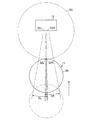
図1ないし図5において、10は走行体装置としての電気掃除装置を示し、この電気掃除装置10は、自律走行体としての電気掃除機本体11と、この電気掃除機本体11の充電用の基地部となるとともに電気掃除機本体11を誘導するビーコン装置としての充電装置(充電台)12とを備えている。そして、電気掃除機本体11は、例えば部屋R内などに配置された中継手段としてのアクセスポイント14との間でBluetooth(登録商標)などの無線通信を用いて通信(送受信)することにより、インターネットなどの(外部)ネットワーク15を介して図示しない外部装置と無線通信可能となっている。   1 to 5, reference numeral 10 denotes a vacuum cleaner as a traveling body device. The vacuum cleaner 10 includes a vacuum cleaner body 11 as an autonomous traveling body and a charging base for the vacuum cleaner body 11. And a charging device (charging base) 12 as a beacon device that guides the vacuum cleaner main body 11. The vacuum cleaner body 11 communicates (transmits / receives) with a wireless communication such as Bluetooth (registered trademark) with an access point 14 as a relay means disposed in the room R, for example, Wireless communication with an external device (not shown) via the (external) network 15 is possible.

この電気掃除機本体11は、本実施形態において、被掃除面としての床面上を自律走行(自走)しつつ床面を掃除する、いわゆる自走式のロボットクリーナである。そして、この電気掃除機本体11は、走行・掃除部として、中空状の本体ケース20、この本体ケース20内に収容された動作部(掃除部)としての電動送風機21、この電動送風機21の吸込側に連通する集塵部22、例えば走行用の複数(一対)の駆動部としての駆動輪23,23、これら駆動輪23,23を駆動させる動作部としての駆動手段であるモータ24,24、旋回用の旋回輪25、本体ケース20の下部に床面に沿って旋回可能に配置された例えば複数(一対)の旋回清掃部(掃除部)としての補助掃除手段であるサイドブラシ26,26、これらサイドブラシ26,26を旋回させる動作部(掃除部)としての旋回駆動手段であるサイドブラシモータ27,27、本体ケース20の下部に回転可能に配置された回転清掃体(掃除部)としての掃除手段である回転ブラシ28、および、この回転ブラシ28を回転駆動させる動作部(掃除部)としての回転駆動手段であるブラシモータ29などを備えている。また、この電気掃除機本体11は、入出力・制御部として、各種センサを有する動作部としてのセンサ部31、受信手段としての走行体側受信手段である受光部32、走行体側送信手段である発光部33、入力操作手段および表示手段の機能を有するタッチパネル34、撮像手段としてのカメラ35、無線通信手段である無線LANデバイス36、および、回路基板などにより構成された制御手段37などを備えている。そして、この電気掃除機本体11には、上記の各部に対して給電する二次電池39を本体ケース20内に備えている。なお、以下、電気掃除機本体11(本体ケース20)の走行方向に沿った方向を前後方向(図3などに示す矢印FR,RR方向)とし、この前後方向に対して交差(直交)する左右方向(両側方向)を幅方向として説明する。   In the present embodiment, the vacuum cleaner body 11 is a so-called self-propelled robot cleaner that cleans the floor surface while autonomously running (self-propelled) on the floor surface as a surface to be cleaned. And this electric vacuum cleaner main body 11 has a hollow main body case 20 as a running / cleaning part, an electric blower 21 as an operation part (cleaning part) accommodated in the main body case 20, and an intake of the electric blower 21 Dust collecting unit 22 communicating with the side, for example, driving wheels 23 and 23 as a plurality of (a pair of) driving units for traveling, motors 24 and 24 as driving means for driving these driving wheels 23 and 23, Side brushes 26 and 26, which are auxiliary cleaning means as, for example, a plurality of (a pair of) swivel cleaning parts (cleaning parts) disposed so as to be turnable along the floor surface at the lower part of the body case 20 Side brush motors 27 and 27, which are turning drive means as an operation part (cleaning part) for turning these side brushes 26 and 26, and a rotary cleaning body (cleaning part) arranged rotatably at the lower part of the body case 20 Rotating brush 28 that is a cleaning means, and rotating this rotating brush 28 A brush motor 29 or the like, which is a rotation driving means, is provided as an operation part (cleaning part) to be driven to roll. The vacuum cleaner main body 11 includes, as an input / output / control unit, a sensor unit 31 as an operation unit having various sensors, a light receiving unit 32 as a traveling body side receiving unit as a receiving unit, and a light emission as a traveling unit side transmitting unit. Unit 33, touch panel 34 having functions of input operation means and display means, camera 35 as imaging means, wireless LAN device 36 as wireless communication means, control means 37 configured by a circuit board and the like . The vacuum cleaner main body 11 includes a secondary battery 39 in the main body case 20 for supplying power to each of the above parts. Hereinafter, the direction along the traveling direction of the vacuum cleaner main body 11 (main body case 20) will be referred to as the front-rear direction (arrow FR and RR directions shown in FIG. 3 and the like), The direction (both sides) will be described as the width direction.

本体ケース20は、例えば合成樹脂などにより平坦な円柱状(円盤状)などに形成されており、円形状の下面の幅方向の中央部の後部寄りの位置に、幅方向に長手状、すなわち横長の吸込口41が開口されている。また、この本体ケース20には、カメラ35が配置されている。   The main body case 20 is formed into a flat columnar shape (disk shape) by, for example, synthetic resin, etc., and is long in the width direction, that is, horizontally long at a position near the rear portion of the center portion in the width direction of the circular bottom surface. The suction port 41 is opened. Further, a camera 35 is disposed in the main body case 20.

吸込口41は、集塵部22を介して電動送風機21の吸込側と連通している。また、この吸込口41には、回転ブラシ28が回転可能に配置されている。   The suction port 41 is in communication with the suction side of the electric blower 21 via the dust collecting unit 22. In addition, the rotary brush 28 is rotatably disposed in the suction port 41.

電動送風機21は、駆動により負圧を発生させて吸込口41から集塵部22へと塵埃を吸い込むもので、例えば吸込側を後方に向けて、かつ、軸方向を前後方向(水平方向)に沿わせて本体ケース20の内部に収容されている。なお、この電動送風機21は、例えば回転ブラシ28などによって集塵部22へと塵埃を掻き上げる構成などの場合には不要となることもあり、必須の構成ではない。   The electric blower 21 generates negative pressure by driving and sucks dust from the suction port 41 to the dust collecting part 22.For example, the suction side is directed rearward and the axial direction is the front-rear direction (horizontal direction). Along the way, it is housed inside the main body case 20. The electric blower 21 may not be necessary in the case of, for example, a configuration in which dust is scraped up to the dust collection unit 22 by the rotating brush 28 or the like, and is not an essential configuration.

集塵部22は、電動送風機21の駆動により吸込口41から吸い込まれた塵埃を捕集するものであり、例えば本体ケース20の後部に位置しており、本体ケース20に対して着脱可能となっている。   The dust collecting unit 22 collects dust sucked from the suction port 41 by driving the electric blower 21, and is located, for example, at the rear part of the main body case 20, and can be attached to and detached from the main body case 20. ing.

各駆動輪23は、電気掃除機本体11(本体ケース20)を床面上で前進方向および後退方向に走行(自律走行)させる、すなわち走行用のものであり、左右幅方向に沿って図示しない回転軸を有する円盤状に形成されている。また、これら駆動輪23は、本体ケース20の下部の前後方向の中心付近の位置にて、吸込口41の両側方に幅方向に互いに離間されて配置されており、幅方向に対称な位置となっている。   Each driving wheel 23 is for traveling (autonomous traveling) the vacuum cleaner body 11 (main body case 20) in the forward and backward directions on the floor surface, that is, for traveling, not shown along the left-right width direction. It is formed in a disk shape having a rotation axis. Further, these drive wheels 23 are disposed in the width direction on both sides of the suction port 41 at positions near the center in the front-rear direction of the lower part of the main body case 20, and are symmetrical with respect to the width direction. It has become.

各モータ24は、例えば駆動輪23のそれぞれに対応して配置されており、各駆動輪23を独立して駆動させることが可能となっている。これらモータ24は、各駆動輪23に直接接続されていてもよいし、ギヤ、あるいはベルトなどの図示しない伝達手段を介して各駆動輪23と接続されていてもよい。   Each motor 24 is arranged corresponding to each of the driving wheels 23, for example, and can drive each driving wheel 23 independently. These motors 24 may be directly connected to each drive wheel 23, or may be connected to each drive wheel 23 via a transmission means (not shown) such as a gear or a belt.

旋回輪25は、本体ケース20の幅方向の略中央部で、かつ、前部に位置しており、床面に沿って旋回可能な従動輪である。   The swivel wheel 25 is a driven wheel that is positioned at the front and substantially at the center in the width direction of the main body case 20, and is capable of swiveling along the floor surface.

各サイドブラシ26は、放射状に突出して床面と接触する複数(例えば3つ)の清掃体としてのブラシ毛43をそれぞれ有している。そして、サイドブラシ26,26は、本体ケース20にて駆動輪23,23の前方でかつ旋回輪25の後方の両側方の位置に配置されている。   Each side brush 26 has brush hairs 43 as a plurality of (for example, three) cleaning bodies that project radially and come into contact with the floor surface. The side brushes 26 and 26 are disposed at positions on both sides of the main body case 20 in front of the drive wheels 23 and 23 and behind the swivel wheel 25.

各サイドブラシモータ27は、各サイドブラシ26を、本体ケース20の幅方向中心側へと、換言すれば右側のサイドブラシ26を左側へと、左側のサイドブラシ26を右側へと、すなわち各サイドブラシ26により塵埃を吸込口41側へと掻き集めるようにそれぞれ回転可能である。   Each side brush motor 27 moves each side brush 26 to the center side in the width direction of the body case 20, in other words, the right side brush 26 to the left side, and the left side brush 26 to the right side, that is, each side. The brushes 26 can be rotated so as to scrape dust to the suction port 41 side.

なお、これらサイドブラシ26およびサイドブラシモータ27は、電動送風機21あるいは回転ブラシ28により充分に掃除できれば必須の構成ではない。   The side brush 26 and the side brush motor 27 are not indispensable as long as they can be sufficiently cleaned by the electric blower 21 or the rotating brush 28.

回転ブラシ28は、長尺状に形成され、吸込口41の幅方向両側部に両端部が回動可能に軸支されている。そして、この回転ブラシ28は、吸込口41から本体ケース20の下面の下方へと突出しており、電気掃除機本体11を床面上に載置した状態で下部が床面に接触して塵埃を掻き取るように構成されている。   The rotary brush 28 is formed in a long shape, and both end portions are pivotally supported on both side portions in the width direction of the suction port 41 so as to be rotatable. The rotating brush 28 protrudes downward from the lower surface of the main body case 20 through the suction port 41, and the lower part contacts the floor surface while the vacuum cleaner main body 11 is placed on the floor surface, and dust is collected. It is configured to scrape.

ブラシモータ29は、本体ケース20の内部に収容されており、機構部としての図示しないギヤ機構を介して回転ブラシ28と接続されている。   The brush motor 29 is housed inside the main body case 20, and is connected to the rotating brush 28 via a gear mechanism (not shown) as a mechanism portion.

なお、これら回転ブラシ28およびブラシモータ29は、電動送風機21あるいはサイドブラシ26,26により充分に掃除できれば必須の構成ではない。   Note that the rotating brush 28 and the brush motor 29 are not essential components as long as they can be sufficiently cleaned by the electric blower 21 or the side brushes 26 and 26.

また、センサ部31は、例えばモータ24の回転数を測定する光エンコーダなどの回転数センサ、壁や家具などの障害物を検出する赤外線センサなどの障害物検出手段(障害物センサ(測距センサ))、床面の段差などを検出する赤外線センサなどの段差検出手段(段差センサ)、および、充電装置12などへの衝突防止用の赤外線センサなどの衝突防止検出手段(衝突防止センサ)などの機能を備え、本体ケース20の上部、外周部(前部および後部)および下部などの各部に配置されている。   The sensor unit 31 includes obstacle detection means (obstacle sensor (ranging sensor) such as a rotation speed sensor such as an optical encoder that measures the rotation speed of the motor 24, and an infrared sensor that detects obstacles such as walls and furniture. )), Step detection means (step sensor) such as an infrared sensor for detecting a step on the floor, and collision prevention detection means (collision prevention sensor) such as an infrared sensor for preventing collision with the charging device 12 etc. It has a function and is arranged in each part such as an upper part, an outer peripheral part (front part and rear part), and a lower part of the main body case 20.

受光部32は、充電装置12から発光された赤外線などを検出することで充電装置12の位置を推定するためのものであり、例えば本体ケース20の外周部前部の左右方向の中央部に対して左右に離間された位置に、左側受光部32Lおよび右側受光部32Rが配置されている。これら受光部32L,32Rは、例えば左右対称に配置されている。   The light receiving unit 32 is for estimating the position of the charging device 12 by detecting infrared light emitted from the charging device 12, for example, with respect to the central portion in the left-right direction of the front portion of the outer periphery of the main body case 20. Thus, the left light receiving part 32L and the right light receiving part 32R are arranged at positions separated left and right. These light receiving portions 32L and 32R are arranged symmetrically, for example.

発光部33は、充電装置12へと赤外線などを発光するものであり、例えば本体ケース20の上部に配置されている。   The light emitting unit 33 emits infrared rays or the like to the charging device 12, and is disposed, for example, on the upper portion of the main body case 20.

タッチパネル34は、使用者が各種設定を直接入力可能であるとともに、電気掃除機本体11に関する各種情報を表示するものであり、例えば本体ケース20の上部に配置されている。   The touch panel 34 allows the user to directly input various settings, and displays various information related to the electric vacuum cleaner main body 11. The touch panel 34 is disposed, for example, on the upper portion of the main body case 20.

カメラ35は、本体ケース20の所定方向、本実施形態では前方から前方上部に亘る領域の画像を撮像するデジタルスチルカメラで、例えば本体ケース20の前部の左右方向の中央部にて本体ケース20の外周部あるいは上部など、すなわち本体ケース20の正面部に配置されている。そして、このカメラ35は、撮像した画像をデータ化して制御手段37に出力することが可能である。   The camera 35 is a digital still camera that captures an image in a predetermined direction of the main body case 20, in this embodiment, from the front to the front upper portion. For example, the main body case 20 is located at the center of the front of the main body case 20 in the left-right direction. The outer peripheral portion or the upper portion of the main body case 20, that is, the front portion of the main body case 20. The camera 35 can convert the captured image into data and output the data to the control means 37.

無線LANデバイス36は、アクセスポイント14およびネットワーク15を介して外部装置と無線通信をするためのものである。したがって、この無線LANデバイス36を介して、ネットワーク15から各種情報を受信したり、例えばスマートフォンなどの外部装置(外部端末)から各種情報を入力したりすることが可能となっている。すなわち、この無線LANデバイス36は、外部装置からネットワーク15を介してアクセスポイント14から送信された外部信号を受信する外部信号受信手段および信号受信手段の機能を有している。   The wireless LAN device 36 is used for wireless communication with an external device via the access point 14 and the network 15. Therefore, it is possible to receive various information from the network 15 via the wireless LAN device 36, or to input various information from an external device (external terminal) such as a smartphone. That is, the wireless LAN device 36 has functions of an external signal receiving unit and a signal receiving unit that receive an external signal transmitted from the access point 14 from the external device via the network 15.

制御手段37は、制御手段本体であるCPU、このCPUによって読み出されるプログラムなどの固定的なデータを格納した格納部であるROM、プログラムによるデータ処理の作業領域となるワークエリアなどの各種メモリエリアを動的に形成するエリア格納部であるRAM、例えばカメラ35で撮像した画像データを記憶する記憶手段であるメモリ、現在の日時などのカレンダ情報を計時するタイマなどを備えている。この制御手段37は、電動送風機21、各モータ24、各サイドブラシモータ27、ブラシモータ29、センサ部31、受光部32、発光部33、タッチパネル34、カメラ35、および、無線LANデバイス36などと電気的に接続され、センサ部31による検出結果に基づいて、電動送風機21、各モータ24、各サイドブラシモータ27、ブラシモータ29などの駆動を制御する掃除モードと、充電装置12を介して二次電池39の充電を行う充電モードと、外部信号に応じてカメラ35による撮像を行う撮像モードと、動作待機中の待機モードとを有している。   The control means 37 includes various memory areas such as a CPU which is a main body of the control means, a ROM which is a storage unit storing fixed data such as a program read by the CPU, and a work area which is a work area for data processing by the program. A RAM that is an area storage unit that is dynamically formed, a memory that is a storage unit that stores image data captured by the camera 35, a timer that measures calendar information such as the current date and time, and the like are provided. The control means 37 includes the electric blower 21, each motor 24, each side brush motor 27, brush motor 29, sensor unit 31, light receiving unit 32, light emitting unit 33, touch panel 34, camera 35, wireless LAN device 36, and the like. Based on the detection result of the sensor unit 31 electrically connected, a cleaning mode for controlling driving of the electric blower 21, each motor 24, each side brush motor 27, the brush motor 29, etc. There are a charging mode in which the secondary battery 39 is charged, an imaging mode in which an image is captured by the camera 35 in accordance with an external signal, and a standby mode in standby.

二次電池39は、電動送風機21、各モータ24、各サイドブラシモータ27、ブラシモータ29、センサ部31、受光部32、発光部33、カメラ35、無線LANデバイス36および制御手段37などに給電するものである。そして、この二次電池39は、例えば本体ケース20の下面の旋回輪25の両側すなわち前部に露出する充電端子45と電気的に接続されている。   The secondary battery 39 supplies power to the electric blower 21, each motor 24, each side brush motor 27, brush motor 29, sensor unit 31, light receiving unit 32, light emitting unit 33, camera 35, wireless LAN device 36, control means 37, etc. To do. The secondary battery 39 is electrically connected to, for example, the charging terminals 45 exposed on both sides of the turning wheel 25 on the lower surface of the main body case 20, that is, the front part.

一方、充電装置12は、ビーコン装置ケースとしての充電装置ケース51、この充電装置ケース51に収容された充電回路52、この充電回路52と電気的に接続された充電用端子53、商用電源と接続される電源コード54、例えば赤外線などにより充電装置12の位置情報などの各種信号を出力する送信手段としてのビーコン装置側送信手段である充電装置発光部55、電気掃除機本体11の発光部33からの発光を受信するビーコン装置側受信手段である充電装置受光部56、例えば赤外線などにより充電装置12の周囲に衝突防止信号SSを出力するビーコン装置側送出手段である充電装置発信部57、および、これら充電装置発光部55、充電装置受光部56および充電装置発信部57などの動作をそれぞれ制御するビーコン装置制御手段である充電装置制御手段58などを備えている。   On the other hand, the charging device 12 includes a charging device case 51 as a beacon device case, a charging circuit 52 accommodated in the charging device case 51, a charging terminal 53 electrically connected to the charging circuit 52, and a commercial power source. Power supply cord 54, for example, charging device light-emitting unit 55 which is a beacon device side transmission means as a transmission means for outputting various signals such as position information of charging device 12 by infrared rays, etc., from light-emitting unit 33 of vacuum cleaner body 11 Charging device light receiving unit 56 which is a beacon device side receiving means for receiving the emitted light, for example, charging device transmission unit 57 which is a beacon device side sending means for outputting a collision prevention signal SS around charging device 12 by infrared rays, and The charging device light emitting unit 55, the charging device light receiving unit 56, the charging device transmitting unit 57, and the like are provided with a charging device control means 58, which is a beacon device control means for controlling operations of the charging device light emitting section 57 and the charging device transmission section 57, respectively.

充電装置ケース51(充電装置12)は、例えば上部に、被写体Pに向けるべき設定方向を指示する方向指示手段59を備え、部屋Rを区画する壁部Wの近傍など、掃除の妨げにならない位置で、かつ、被写体Pに対して方向指示手段59により示された方向が向くように配置されている。   The charging device case 51 (charging device 12) includes, for example, a direction instruction means 59 for instructing a setting direction to be directed toward the subject P at the top, and a position that does not interfere with cleaning, such as the vicinity of the wall W that partitions the room R. And, it is arranged so that the direction indicated by the direction instructing means 59 faces the subject P.

ここで、方向指示手段59は、本実施形態では例えば方向を示す矢印とするが、例えばその示す方向の面などに配置されたアイコンなどのマークなどとすることもできるし、例えば充電装置ケース51の一部の色を変えて方向を示したり、充電装置ケース51の形状によって方向を示したりすることなども可能である。すなわち、方向指示手段59とは、予め充電装置12に被写体Pに向けるべき設定方向を設定するものである。したがって、方向指示手段59とは、設定方向を使用者が特定できれば、充電装置12に予め備わっている構造物や形状などをそのまま利用してもよい。   Here, the direction instruction means 59 is, for example, an arrow indicating a direction in the present embodiment, but may be, for example, a mark such as an icon arranged on a surface in the direction indicated, for example, a charging device case 51 It is also possible to indicate the direction by changing some of the colors, or indicate the direction depending on the shape of the charging device case 51. That is, the direction instructing means 59 sets the setting direction to be directed to the subject P in the charging device 12 in advance. Therefore, the direction instructing unit 59 may use a structure, a shape, or the like provided in advance in the charging device 12 as long as the user can specify the setting direction.

充電回路52は、充電用端子53に充電端子45が接続された電気掃除機本体11の二次電池39を充電する定電流回路などである。   The charging circuit 52 is a constant current circuit for charging the secondary battery 39 of the vacuum cleaner body 11 in which the charging terminal 45 is connected to the charging terminal 53.

充電用端子53は、充電装置ケース51の下部に露出しており、充電装置12へと移動(帰還)した電気掃除機本体11の充電端子45が機械的および電気的に接続されるものである。   The charging terminal 53 is exposed at a lower portion of the charging device case 51, and is connected mechanically and electrically to the charging terminal 45 of the vacuum cleaner body 11 that has moved (returned) to the charging device 12. .

電源コード54は、充電回路52、充電装置発光部55、充電装置受光部56、充電装置発信部57および充電装置制御手段58と電気的に接続されており、壁部Wなどに設置されたコンセントと接続されることで、商用電源から給電可能とするものである。   The power cord 54 is electrically connected to the charging circuit 52, the charging device light emitting portion 55, the charging device light receiving portion 56, the charging device transmitting portion 57, and the charging device control means 58, and is an outlet installed on the wall W or the like. So that power can be supplied from a commercial power source.

充電装置発光部55は、方向指示手段59により指示される方向に対して所定の関係を有する方向(所定角度をなす方向)、本実施形態では、方向指示手段59により指示される方向に対して90°交差する方向に向けて電気掃除機本体11へと赤外線などを発光するものであり、例えば充電装置ケース51の側部の中央部に互いに離間された位置に、充電装置左側発光部55Lおよび充電装置右側発光部55Rが配置されている。なお、この充電装置発光部55は、常時発光していてもよいし、例えば電気掃除機本体11の発光部33からの発光を充電装置受光部56により受光したときに発光してもよい。   The charging device light emitting unit 55 has a predetermined relationship with respect to the direction instructed by the direction instructing unit 59 (a direction forming a predetermined angle), and in the present embodiment, in the direction instructed by the direction instructing unit 59. It emits infrared rays or the like toward the vacuum cleaner main body 11 in a direction intersecting by 90 °. For example, the left side light emitting unit 55L of the charging device and the left side light emitting unit 55L and A charging device right side light emitting unit 55R is arranged. The charging device light emitting unit 55 may emit light at all times, or may emit light when light from the light emitting unit 33 of the electric vacuum cleaner main body 11 is received by the charging device light receiving unit 56, for example.

充電装置受光部56は、電気掃除機本体11の発光部33から発光された赤外線などを検出することで電気掃除機本体11と充電装置12との位置関係を把握するためのものであり、例えば充電装置ケース51の上部に配置されている。   The charging device light receiving unit 56 is for grasping the positional relationship between the vacuum cleaner main body 11 and the charging device 12 by detecting infrared light emitted from the light emitting unit 33 of the vacuum cleaner main body 11, for example, Arranged at the top of the charging device case 51.

充電装置発信部57は、例えば充電装置12を中心とする所定半径(例えば30cm程度)の位置に、電気掃除機本体11がそれ以上接近しないようにするための衝突防止信号SSを出力するものであり、例えば充電装置ケース51の上部の中央部などに配置されている。   The charging device transmitter 57 outputs a collision prevention signal SS for preventing the vacuum cleaner main body 11 from approaching the position of a predetermined radius (for example, about 30 cm) centered on the charging device 12, for example. For example, it is arranged at the center of the upper part of the charging device case 51 or the like.

充電装置制御手段58は、例えば充電装置発光部55から発光する赤外線信号を生成したり、充電装置受光部56により受信した電気掃除機本体11の発光部33からの赤外線信号を処理したりするものである。そして、この充電装置制御手段58は、充電回路52を介して二次電池39を充電するための充電モードと、電気掃除機本体11をカメラ35による撮像が可能な位置へと誘導する撮像モードと、動作待機中の待機モードとを有している。   The charging device control means 58 generates, for example, an infrared signal emitted from the charging device light emitting unit 55, or processes the infrared signal received from the charging device light receiving unit 56 from the light emitting unit 33 of the vacuum cleaner body 11. It is. The charging device control means 58 includes a charging mode for charging the secondary battery 39 via the charging circuit 52, and an imaging mode for guiding the vacuum cleaner body 11 to a position where the camera 35 can capture images. And a standby mode for waiting for operation.

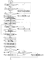
次に、上記第1の実施形態の動作を、図6に示すフローチャートも参照しながら説明する。   Next, the operation of the first embodiment will be described with reference to the flowchart shown in FIG.

一般に、自律走行型の電気掃除機本体11は、電気掃除機本体11が掃除をする掃除作業と、充電装置12によって二次電池39を充電する充電作業とに大別されるが、本実施形態では、これら作業に加えて、被写体P(例えば檻Cに入れられた犬などのペット)を撮像する撮像作業を行う。   In general, the autonomously traveling electric vacuum cleaner main body 11 is roughly divided into a cleaning operation in which the electric vacuum cleaner main body 11 cleans and a charging operation in which the secondary battery 39 is charged by the charging device 12, but this embodiment Then, in addition to these operations, an imaging operation for imaging the subject P (for example, a pet such as a dog placed in the bag C) is performed.

(掃除作業)
電気掃除機本体11は、予め設定された掃除開始時刻となると、待機モードから掃除モードとなった制御手段37が電動送風機21、駆動輪23,23(モータ24,24)、サイドブラシ26,26(サイドブラシモータ27,27)および回転ブラシ28(ブラシモータ29)などを駆動させ、例えば充電装置12から離脱して、駆動輪23,23により床面上を自律走行しながら掃除を開始する。なお、掃除の開始位置は、電気掃除機本体11の走行開始位置、あるいは部屋Rの出入り口など、任意の場所に設定可能である。
(Cleaning work)
In the vacuum cleaner main body 11, when the cleaning start time set in advance is reached, the control means 37 that is changed from the standby mode to the cleaning mode is operated by the electric blower 21, the drive wheels 23 and 23 (motors 24 and 24), and the side brushes 26 and 26. (Side brush motors 27 and 27), rotating brush 28 (brush motor 29), and the like are driven, detached from the charging device 12, for example, and cleaning is started while driving autonomously on the floor surface by the drive wheels 23 and 23. The cleaning start position can be set at any place such as the travel start position of the electric vacuum cleaner main body 11 or the entrance / exit of the room R.

走行中、制御手段37は、センサ部31を介して例えば掃除領域の周囲を囲む壁部や掃除領域内の障害物などとの距離、および、床面の段差などを検出することで電気掃除機本体11(本体ケース20)の走行状態を監視し、このセンサ部31からの検出に対応して駆動輪23,23(モータ24,24)を駆動させることで、障害物や段差などを回避しながら電気掃除機本体11を床面上で走行させる。   During traveling, the control means 37 detects, for example, the distance from the wall surrounding the periphery of the cleaning area or an obstacle in the cleaning area, the step of the floor surface, etc. By monitoring the running state of the main body 11 (main body case 20) and driving the drive wheels 23 and 23 (motors 24 and 24) in response to detection from the sensor unit 31, obstacles and steps are avoided. While running the vacuum cleaner body 11 on the floor.

そして、この電気掃除機本体11は、旋回駆動されたサイドブラシ26,26により塵埃を吸込口41へと掻き集め、電動送風機21の駆動によって発生した負圧が集塵部22を介して作用した吸込口41により、床面上の塵埃を空気とともに吸い込む。また、回転駆動された回転ブラシ28が床面の塵埃を集塵部22へと掻き取る。   The vacuum cleaner main body 11 collects dust to the suction port 41 by the side brushes 26 and 26 that are driven to rotate, and the suction generated by the negative pressure generated by the driving of the electric blower 21 via the dust collection unit 22 Dust on the floor surface is sucked together with air through the mouth 41. In addition, the rotary brush 28 that is driven to rotate scrapes off dust on the floor surface to the dust collecting unit 22.

吸込口41から空気とともに吸い込まれた塵埃は、集塵部22に分離捕集され、塵埃が分離された空気は電動送風機21に吸い込まれ、この電動送風機21を冷却した後、排気風となって本体ケース20に設けられた図示しない排気口から外部へと排気される。   The dust sucked together with the air from the suction port 41 is separated and collected by the dust collecting unit 22, and the air from which the dust is separated is sucked into the electric blower 21, and after cooling the electric blower 21, it becomes exhaust air. The air is exhausted from an exhaust port (not shown) provided in the main body case 20 to the outside.

掃除領域の掃除が完了した、または、二次電池39の容量が所定量まで低下して掃除を完了させるのに不足している(二次電池39の電圧が放電終止電圧近傍まで低下している)などの所定条件時には、制御手段37は、発光部33から掃除モードを終了して充電モードに移行したい旨の信号を送信する。この信号を充電装置受光部56で受光した充電装置12は、充電装置制御手段58が充電装置発光部55から電気掃除機本体11を充電装置12へと帰還(移動)させるように誘導する帰還信号を送信する。そして、この帰還信号を受光部32により受信した電気掃除機本体11は、制御手段37により駆動輪23,23(モータ24,24)を駆動させて充電装置12へと所定距離接近するように走行する。このように、電気掃除機本体11の受光部32および発光部33と充電装置12の充電装置発光部55および充電装置受光部56との間での送受信の繰り返しにより電気掃除機本体11を漸次接近させ、この充電装置12まで移動(帰還)した状態で充電用端子53に充電端子45を(機械的および電気的に)接続させ、各部を停止させて掃除作業を終了する。   Cleaning of the cleaning area has been completed, or the capacity of the secondary battery 39 has fallen to a predetermined amount and is insufficient to complete the cleaning (the voltage of the secondary battery 39 has dropped to near the discharge end voltage) ) And the like, the control unit 37 transmits a signal from the light emitting unit 33 to end the cleaning mode and shift to the charging mode. The charging device 12 that has received this signal by the charging device light receiving unit 56, the charging device control means 58, a feedback signal that guides the charging device light emitting unit 55 to return (move) the vacuum cleaner body 11 to the charging device 12. Send. Then, the vacuum cleaner main body 11 that has received the feedback signal by the light receiving unit 32 drives the drive wheels 23 and 23 (motors 24 and 24) by the control means 37 so as to approach the charging device 12 by a predetermined distance. To do. Thus, the vacuum cleaner main body 11 is gradually approached by repeating transmission and reception between the light receiving unit 32 and the light emitting unit 33 of the vacuum cleaner main body 11 and the charging device light emitting unit 55 and the charging device light receiving unit 56 of the charging device 12. The charging terminal 45 is connected (mechanically and electrically) to the charging terminal 53 while being moved (returned) to the charging device 12, and each part is stopped to complete the cleaning operation.

(充電作業)
充電装置12に電気掃除機本体11が接続された後、所定のタイミング、例えば予め設定された充電開始時刻となったとき、あるいは電気掃除機本体11が充電装置12に接続されてから所定時間が経過したときなどに、制御手段37および充電装置制御手段58はそれぞれ充電モードに移行して充電回路52を駆動させ、二次電池39の充電を開始する。そして、二次電池39の電圧が所定の使用可能電圧まで上昇したと判断すると、制御手段37および充電装置制御手段58が充電回路52による充電を停止させて充電作業を終了し、制御手段37および充電装置制御手段58がそれぞれ待機モードとなる。
(Charging work)
After the electric vacuum cleaner main body 11 is connected to the charging device 12, a predetermined time, for example, a predetermined time after the electric vacuum cleaner main body 11 is connected to the charging device 12 when a preset charging start time is reached. When the time elapses, the control unit 37 and the charging device control unit 58 shift to the charging mode, drive the charging circuit 52, and start charging the secondary battery 39. When it is determined that the voltage of the secondary battery 39 has increased to a predetermined usable voltage, the control unit 37 and the charging device control unit 58 stop the charging by the charging circuit 52 to end the charging operation, and the control unit 37 and The charging device control means 58 is in the standby mode.

(撮像作業)
制御手段37は、外部装置からネットワーク15を介して送信されたカメラ35での撮像を指示する外部信号である撮像指示信号を、アクセスポイント14を介して無線LANデバイス36により受信したかどうかを例えばリアルタイム、あるいは所定時間毎に判断する(ステップ1)。なお、外部装置と電気掃除機本体11との無線通信については、例えば外部装置毎、および、電気掃除機本体11毎にIDおよびパスワードなどを設定して接続時に認証を要求することで、不正な信号に関しては受信できないようにすることが好ましい。
(Imaging work)
The control unit 37 determines whether or not the wireless LAN device 36 has received an imaging instruction signal, which is an external signal instructing imaging with the camera 35 transmitted from the external device via the network 15, via the access point 14, for example. Judgment is made in real time or every predetermined time (step 1). Regarding wireless communication between the external device and the vacuum cleaner body 11, for example, by setting an ID and password for each external device and each vacuum cleaner body 11 and requesting authentication at the time of connection, it is illegal. It is preferable not to receive the signal.

このステップ1において、外部装置からネットワーク15を介して送信されたカメラ35での撮像を指示する外部信号である撮像指示信号を無線LANデバイス36により受信したと判断したときには、まず、制御手段37が、そのモードに拘らず二次電池39の残容量を検出して、二次電池39の残容量が、カメラ35による撮像が可能な撮像可能容量であるかどうかを判断する(ステップ2)。なお、以下、撮像可能容量とは、例えば被写体Pを撮像する所定の撮像位置までの往復が可能で、かつ、カメラ35による撮像および撮像した画像データを無線LANデバイス36を介してネットワーク15から外部装置へと送信可能な容量とする。   When it is determined in step 1 that the wireless LAN device 36 has received an imaging instruction signal that is an external signal for instructing imaging with the camera 35 transmitted from the external device via the network 15, first, the control means 37 Regardless of the mode, the remaining capacity of the secondary battery 39 is detected to determine whether or not the remaining capacity of the secondary battery 39 is an imageable capacity that can be captured by the camera 35 (step 2). In the following description, the imageable capacity is, for example, reciprocal to a predetermined imaging position where the subject P is imaged, and the image captured by the camera 35 and the captured image data are externally transmitted from the network 15 via the wireless LAN device 36. The capacity can be transmitted to the device.

そして、ステップ2において、二次電池39の残容量が撮像可能容量でないと判断した場合には、制御手段37が無線LANデバイス36を用いて例えば外部装置に撮像不可能であることを報知し(ステップ3)、撮像指示信号を無視してステップ1に戻る。   If it is determined in step 2 that the remaining capacity of the secondary battery 39 is not an imageable capacity, the control unit 37 uses the wireless LAN device 36 to notify the external device that imaging is not possible, for example ( Step 3), ignoring the imaging instruction signal and returning to Step 1.

一方、ステップ2において、二次電池39の残容量が撮像可能容量以上であると判断した場合には、制御手段37(および充電装置制御手段58)は、モードを判断する(ステップ4)。   On the other hand, if it is determined in step 2 that the remaining capacity of the secondary battery 39 is greater than or equal to the imageable capacity, the control means 37 (and the charging device control means 58) determines the mode (step 4).

このステップ4において、充電モードまたは待機モードであると判断した場合には、制御手段37は駆動輪23,23(モータ24,24)を駆動させ、電気掃除機本体11を例えば充電装置12から所定距離(例えば30cm以上)離間させて(ステップ5)、撮像モードに移行する(ステップ6)。   If it is determined in step 4 that the charging mode or the standby mode is selected, the control means 37 drives the drive wheels 23 and 23 (motors 24 and 24), and the electric vacuum cleaner main body 11 is moved from the charging device 12, for example. A distance (for example, 30 cm or more) is set apart (step 5), and the mode is shifted to the imaging mode (step 6).

一方、ステップ4において、掃除モードであると判断した場合には、制御手段37は、例えば電動送風機21、サイドブラシ26,26(サイドブラシモータ27,27)および回転ブラシ28(ブラシモータ29)の駆動を停止させて掃除を中断し(ステップ7)、ステップ6に進んで撮像モードに移行する。   On the other hand, if it is determined in step 4 that the mode is the cleaning mode, the control means 37 controls, for example, the electric blower 21, the side brushes 26 and 26 (side brush motors 27 and 27), and the rotary brush 28 (brush motor 29). The driving is stopped to stop the cleaning (step 7), and the process proceeds to step 6 to shift to the imaging mode.

そして、ステップ6の撮像モードにおいては、まず、電気掃除機本体11の発光部33から充電装置12に向けて撮像モードである旨の信号を送信する(ステップ8)。充電装置12では、電気掃除機本体11から撮像モードである旨の信号を受信したときに、充電装置制御手段58が撮像モードに移行し、充電装置発光部55の充電装置左側発光部55Lおよび充電装置右側発光部55Rからそれぞれ誘導信号SL,SRを出力するとともに、充電装置発信部57から所定の衝突防止信号SSを出力する。本実施形態では、例えば被写体Pの正面方向(図1の上下方向)に対して交差する方向に向けて、充電装置発光部55の充電装置左側発光部55Lおよび充電装置右側発光部55Rからそれぞれ誘導信号SL,SRを出力する。換言すれば、誘導信号SL,SRによる充電装置12への電気掃除機本体11の誘導方向が、被写体Pに向かう方向に対して交差(直交)する方向となっている。これら誘導信号SL,SRは、例えば互いにコードを異ならせたり、あるいは同コードの信号を時分割で出力したりすることにより、電気掃除機本体11側で識別可能となっている。したがって、ステップ8の後、制御手段37は、充電装置12側からの応答があるかどうかを判断し(ステップ9)、所定時間応答がない場合には、制御手段37が駆動輪23,23(モータ24,24)を駆動させて電気掃除機本体11(本体ケース20)を走行させ(ステップ10)、ステップ8に戻る。このステップ10の制御は、ステップ9において充電装置12側からの応答がないということが、電気掃除機本体11からの信号が充電装置12に受信されていない、または、充電装置12からの応答を電気掃除機本体11が受信できない位置にあるものと想定し、電気掃除機本体11(本体ケース20)を部屋R内でさまよわせて、充電装置12が信号を受信できる位置、あるいは充電装置12からの信号を受信できる位置を探すものである。したがって、このステップ10において、電気掃除機本体11(本体ケース20)は、例えばその位置で旋回させたり、ランダムに走行させたり、所定半径の円に沿って走行させたりすることで、充電装置12とのやり取りが可能な位置を見つけ出すことができる。   Then, in the imaging mode of step 6, first, a signal indicating that the imaging mode is set is transmitted from the light emitting unit 33 of the vacuum cleaner body 11 to the charging device 12 (step 8). When the charging device 12 receives a signal indicating that it is in the imaging mode from the vacuum cleaner body 11, the charging device control means 58 shifts to the imaging mode, and the charging device left-side light emitting unit 55L of the charging device light-emitting unit 55 and the charging device Induction signals SL and SR are output from the device right side light emitting unit 55R, respectively, and a predetermined collision prevention signal SS is output from the charging device transmission unit 57. In the present embodiment, for example, guidance is performed from the charging device left side light emitting unit 55L and the charging device right side light emitting unit 55R of the charging device light emitting unit 55 in a direction intersecting the front direction of the subject P (vertical direction in FIG. 1). Outputs signals SL and SR. In other words, the induction direction of the vacuum cleaner main body 11 to the charging device 12 by the induction signals SL and SR is a direction that intersects (orthogonally) with respect to the direction toward the subject P. These induction signals SL and SR can be identified on the main body 11 side of the vacuum cleaner, for example, by making the codes different from each other or by outputting signals of the same code in a time-sharing manner. Therefore, after step 8, the control means 37 determines whether or not there is a response from the charging device 12 side (step 9), and if there is no response for a predetermined time, the control means 37 causes the drive wheels 23 and 23 ( The motors 24, 24) are driven to run the vacuum cleaner main body 11 (main body case 20) (step 10), and the process returns to step 8. The control of step 10 is that there is no response from the charging device 12 side in step 9, that the signal from the vacuum cleaner body 11 is not received by the charging device 12, or the response from the charging device 12 is Assuming that the vacuum cleaner main body 11 is in a position where it cannot be received, the vacuum cleaner main body 11 (main body case 20) is swung in the room R, and the charging device 12 can receive the signal, or the charging device 12 The position where the signal from can be received is searched. Therefore, in this step 10, the electric vacuum cleaner main body 11 (main body case 20) is turned, for example, rotated at that position, randomly traveled, or traveled along a circle with a predetermined radius. You can find a position where you can communicate with.

一方、ステップ9において、充電装置12側からの応答があったと判断した場合には、制御手段37は駆動輪23,23(モータ24,24)を駆動させ、誘導信号SL,SRにしたがって充電装置12へと所定距離接近するように電気掃除機本体11(本体ケース20)を走行させる(ステップ11)。   On the other hand, if it is determined in step 9 that there is a response from the charging device 12 side, the control means 37 drives the drive wheels 23 and 23 (motors 24 and 24), and the charging device according to the induction signals SL and SR. The vacuum cleaner main body 11 (main body case 20) is caused to travel so as to approach the predetermined distance to 12 (step 11).

このとき、誘導信号SL,SRは、図5に示すように、例えば充電装置左側発光部55Lから充電装置12の正面に向かって左側の領域に放射状(長楕円状)に出力されるとともに、充電装置右側発光部55Rから充電装置12の正面に向かって右側の領域に放射状(長楕円状)に出力される。具体的に、電気掃除機本体11(本体ケース20)は、例えば最初に誘導信号SLのみを受光部32の左側受光部32Lで受信した場合には、相対的に左方向に向かって走行し、最初に誘導信号SRのみを受光部32の右側受光部32Rで受信した場合には、相対的に右方向に向かって走行するように駆動輪23,23(モータ24,24)を駆動制御する。そして、電気掃除機本体11(本体ケース20)は、誘導信号SLを左側受光部32Lによって受信し、かつ、誘導信号SL,SRを右側受光部32Rによって受信する位置を走行するように駆動輪23,23(モータ24,24)を駆動制御することで、誘導信号SL,SRが互いに重なる領域(例えば10〜20cm程度の幅)に沿って直線状に充電装置12に向かって走行できる。   At this time, as shown in FIG. 5, for example, the induction signals SL and SR are output radially (long elliptical shape) to the left region from the left side light emitting unit 55L of the charging device toward the front of the charging device 12, and charged. From the device right side light emitting unit 55R toward the front of the charging device 12, it is output radially (long elliptical shape) in the right region. Specifically, for example, when the vacuum cleaner body 11 (main body case 20) first receives only the induction signal SL at the left light receiving unit 32L of the light receiving unit 32, it travels relatively to the left, First, when only the guide signal SR is received by the right light receiving unit 32R of the light receiving unit 32, the drive wheels 23 and 23 (motors 24 and 24) are driven and controlled to travel relatively to the right. Then, the vacuum cleaner main body 11 (main body case 20) receives the induction signal SL by the left light receiving unit 32L, and travels at a position where the induction signals SL and SR are received by the right light reception unit 32R. , 23 (motors 24, 24) can be driven linearly toward the charging device 12 along a region where the induction signals SL, SR overlap each other (for example, a width of about 10 to 20 cm).

次いで、制御手段37は、衝突防止信号SSをセンサ部31によって受信したかどうかにより、電気掃除機本体11が充電装置12に対して所定距離の位置になったかどうかを判断する(ステップ12)。ここで、衝突防止信号SSは、例えば充電装置12を中心とする所定半径(例えば30cm)の円内に出力され、この半径の内側に電気掃除機本体11が入らないように設定されている。そして、このステップ12において、電気掃除機本体11が充電装置12に対して所定距離の位置になっていないと判断したときには、ステップ9に戻る。また、このステップ12において、電気掃除機本体11が充電装置12に対して所定距離の位置になったと判断したときには、その位置で走行を停止し(ステップ13)、駆動輪23,23(モータ24,24)の駆動を制御して方向指示手段59により指示される方向、すなわち被写体Pに向けて本体ケース20をカメラ35とともに所定角度(例えば90°)旋回させ、図1に示すように、本体ケース20の前部に配置され充電装置12を向いていたカメラ35を被写体Pの方向に向けて静止画像を撮像し、この画像データをメモリに記憶するとともに、無線LANデバイス36によってネットワーク15を介して外部装置へと送信する(ステップ14)。すなわち、方向指示手段59により指示される方向を被写体Pに向けて充電装置12を設置していることにより、この指示される方向をカメラ35によって撮像すると、被写体Pが撮像されることとなる。なお、本体ケース20の旋回角度は、センサ部31により検出した左右のモータ24,24の回転数差により制御手段37が判断する。   Next, the control means 37 determines whether or not the electric vacuum cleaner main body 11 is at a predetermined distance from the charging device 12 based on whether or not the collision prevention signal SS is received by the sensor unit 31 (step 12). Here, the collision prevention signal SS is output, for example, within a circle having a predetermined radius (for example, 30 cm) with the charging device 12 as the center, and the electric vacuum cleaner main body 11 is set not to enter inside the radius. If it is determined in step 12 that the vacuum cleaner body 11 is not located at a predetermined distance from the charging device 12, the process returns to step 9. Also, in this step 12, when it is determined that the vacuum cleaner main body 11 has reached a predetermined distance from the charging device 12, traveling stops at that position (step 13), and the drive wheels 23, 23 (motor 24 , 24) is controlled to turn the body case 20 together with the camera 35 at a predetermined angle (for example, 90 °) toward the direction indicated by the direction indicating means 59, that is, the subject P, as shown in FIG. The camera 35 disposed at the front of the case 20 and facing the charging device 12 is pointed in the direction of the subject P to take a still image, and this image data is stored in the memory, and the wireless LAN device 36 via the network 15 To the external device (step 14). That is, since the charging device 12 is installed with the direction indicated by the direction indicating means 59 facing the subject P, the subject P is imaged when the camera 35 captures the indicated direction. Note that the turning angle of the main body case 20 is determined by the control means 37 based on the difference in rotational speed between the left and right motors 24 and 24 detected by the sensor unit 31.

そして、撮像が終了したら、制御手段37は発光部33から撮像モードを終了したい旨の撮像終了信号を送信する(ステップ15)。そして、この撮像終了信号を充電装置12の充電装置受光部56により受信すると、充電装置制御手段58が充電装置発信部57からの衝突防止信号SSの出力を停止する(ステップ16)。また、制御手段37は撮像モードに移行する直前のモードを判断する(ステップ17)。   When the imaging is completed, the control unit 37 transmits an imaging end signal indicating that the imaging mode is to be ended from the light emitting unit 33 (step 15). When this imaging end signal is received by the charging device light receiving unit 56 of the charging device 12, the charging device control means 58 stops outputting the collision prevention signal SS from the charging device transmission unit 57 (step 16). Further, the control means 37 determines the mode immediately before shifting to the imaging mode (step 17).

このステップ17において、充電モードまたは待機モードであったと判断したときには、制御手段37が掃除作業時と同様に電気掃除機本体11を充電装置12に帰還させ、充電装置制御手段58とともに充電モードに移行する(ステップ18)。   When it is determined in step 17 that the charging mode or the standby mode is set, the control means 37 returns the main body 11 of the vacuum cleaner to the charging device 12 in the same manner as during the cleaning operation, and the charging mode is transferred to the charging mode together with the charging device control means 58. (Step 18).

一方、ステップ17において、掃除モードであった(掃除モードを中断して撮像モードに移行した)と判断したときには、制御手段37が二次電池39の容量が残りの掃除に要する容量と比較して充分であるかどうかを判断し(ステップ19)、容量が充分と判断したときには制御手段37が電動送風機21、サイドブラシ26,26(サイドブラシモータ27,27)および回転ブラシ28(ブラシモータ29)を駆動させて掃除に復帰し(ステップ20)、容量が不充分と判断したときには、ステップ18に進み、掃除作業時と同様に電気掃除機本体11を充電装置12に帰還させて充電モードに移行する。なお、撮像モードに移行する直前のモードに拘らず、撮像モードが終了した場合には必ず充電モードに移行するように制御してもよい。この場合、二次電池39の充電が終了した後には、例えばそのまま待機モードに移行してもよいし、この充電の後、撮像モードに移行する直前のモードが掃除モードであった場合にのみ、掃除に復帰してもよい。   On the other hand, when it is determined in step 17 that the cleaning mode is set (the cleaning mode is interrupted and the mode is changed to the imaging mode), the control means 37 compares the capacity of the secondary battery 39 with the remaining capacity required for cleaning. It is determined whether or not the capacity is sufficient (step 19), and when it is determined that the capacity is sufficient, the control means 37 controls the electric blower 21, the side brushes 26 and 26 (side brush motors 27 and 27), and the rotating brush 28 (brush motor 29). Drive to return to cleaning (step 20), and if it is determined that the capacity is insufficient, proceed to step 18 and return the vacuum cleaner body 11 to the charging device 12 and shift to the charging mode in the same way as during the cleaning operation. To do. Regardless of the mode immediately before the transition to the imaging mode, the control may be performed such that the transition to the charging mode is always performed when the imaging mode ends. In this case, after the charging of the secondary battery 39 is finished, for example, the standby mode may be shifted as it is, or only when the mode immediately before the transition to the imaging mode is the cleaning mode after the charging. You may return to cleaning.

すなわち、電気掃除機本体を被写体の近傍の所定位置まで充電装置からの誘導信号により単に誘導するだけでは、電気掃除機本体の本体ケースの前部に搭載したカメラによって充電装置を撮像することとなる。このため、充電装置を被写体の正面などに配置して、被写体を充電装置ごと撮像するようにすることが考えられるものの、この場合でも撮像した画像中に映り込んだ充電装置により被写体の撮像が妨げられる。そこで、上記第1の実施形態では、撮像モードで本体ケース20(電気掃除機本体11)が充電装置12に対して所定距離の位置となったときにカメラ35を本体ケース20とともに充電装置12に予め設定された、被写体Pに向けるべき設定方向、本実施形態では方向指示手段59により指示される方向に向けて所定角度旋回させることにより、その方向に位置する被写体Pにカメラ35を向けることができ、電気掃除機本体11を所定位置(撮像位置)まで確実に誘導しつつ、誘導した充電装置12を撮像することなく、被写体Pのみを確実にカメラ35で撮像できる。   That is, if the vacuum cleaner body is simply guided to a predetermined position near the subject by the induction signal from the charging device, the charging device is imaged by the camera mounted on the front part of the body case of the vacuum cleaner body. . For this reason, it is conceivable to place the charging device in front of the subject so that the subject is imaged together with the charging device, but even in this case, the charging device reflected in the captured image prevents the imaging of the subject. It is done. Therefore, in the first embodiment, when the main body case 20 (the vacuum cleaner main body 11) is at a predetermined distance from the charging device 12 in the imaging mode, the camera 35 is connected to the charging device 12 together with the main body case 20. The camera 35 can be directed to the subject P located in that direction by turning a predetermined angle toward the preset setting direction to be directed to the subject P, in this embodiment, the direction indicated by the direction indicating means 59 in this embodiment. Thus, it is possible to reliably image only the subject P with the camera 35 without imaging the charged charging device 12 while reliably guiding the vacuum cleaner body 11 to a predetermined position (imaging position).

なお、上記の撮像作業(撮像モード)においては、二次電池39の電力を有効利用するために電動送風機21、サイドブラシ26,26(サイドブラシモータ27,27)および回転ブラシ28(ブラシモータ29)などの掃除部の駆動を停止させたが、二次電池39の残容量に余裕がある場合にはこれらを動作させて同時に掃除をしてもよい。   In the above imaging operation (imaging mode), the electric blower 21, the side brushes 26 and 26 (side brush motors 27 and 27), and the rotating brush 28 (brush motor 29) are used to effectively use the power of the secondary battery 39. However, if the remaining capacity of the secondary battery 39 has a margin, these may be operated and cleaned at the same time.

次に、第2の実施形態を図7を参照して説明する。なお、上記第1の実施形態と同様の構成および作用については、同一符号を付してその説明を省略する。   Next, a second embodiment will be described with reference to FIG. In addition, about the structure and effect | action similar to the said 1st Embodiment, the same code | symbol is attached | subjected and the description is abbreviate | omitted.

この第2の実施形態は、上記第1の実施形態の撮像モードにおいて、カメラ35で撮像する際に、カメラ35を向ける方向を所定角度ずつ旋回させながら撮像するものである。   In the second embodiment, when the image is taken by the camera 35 in the image pickup mode of the first embodiment, the image is taken while turning the direction in which the camera 35 is directed by a predetermined angle.

すなわち、ステップ13の後、制御手段37は、駆動輪23,23(モータ24,24)の駆動を制御して本体ケース20をカメラ35とともに所定角度回動させてカメラ35により静止画像を撮像し、この画像データをメモリに記憶するとともに、無線LANデバイス36によってネットワーク15を介して外部装置へと送信する(ステップ31)。次いで、制御手段37は、本体ケース20(カメラ35)が所定の最大回動角度、例えば360°以上回動したかどうかを判断する(ステップ32)。このステップ32において、最大回動角度以上回動したと判断した場合には、ステップ15に進み、最大回動角度以上回動していないと判断した場合には、ステップ31に戻る。なお、カメラ35により撮像した画像データは、撮像する毎に外部装置に送信する他に、全ての撮像が終了してからまとめて外部装置に送信してもよい。   That is, after step 13, the control means 37 controls the drive of the drive wheels 23, 23 (motors 24, 24), rotates the body case 20 together with the camera 35 by a predetermined angle, and takes a still image with the camera 35. The image data is stored in the memory and transmitted to the external apparatus via the network 15 by the wireless LAN device 36 (step 31). Next, the control means 37 determines whether or not the main body case 20 (camera 35) has rotated a predetermined maximum rotation angle, for example, 360 ° or more (step 32). If it is determined in this step 32 that the rotation is greater than the maximum rotation angle, the process proceeds to step 15. If it is determined that the rotation is not greater than the maximum rotation angle, the process returns to step 31. Note that the image data captured by the camera 35 may be transmitted to the external device collectively after all the image capturing is completed, in addition to being transmitted to the external device every time it is captured.

このように、上記第2の実施形態によれば、撮像モードでカメラ35を本体ケース20とともに所定角度ずつ旋回させながら撮像することにより、被写体Pだけでなく、被写体Pの周囲の部屋Rの状況をもカメラ35で撮像できる。この結果、被写体Pを異なる角度から撮像した画像を得ることができるとともに、被写体Pの様子だけでなく、例えば外出中の自宅の様子(例えば窓が開けたままになっていないか、電気が点いたままになっていないかなど)をも監視および確認できる。   As described above, according to the second embodiment, not only the subject P but also the state of the room R around the subject P is obtained by taking an image while rotating the camera 35 with the main body case 20 by a predetermined angle in the imaging mode. Can also be captured by the camera 35. As a result, it is possible to obtain images obtained by imaging the subject P from different angles, and not only the state of the subject P but also the state of the home while going out (for example, whether the window is left open, You can also monitor and check if you have left.

なお、上記各実施形態では、本体ケース20ごとカメラ35を回動させたが、例えばカメラ35を本体ケース20に対して別個に回動可能に設け、カメラ35のみを回動させてもよい。この場合には、カメラ35の向きを検出する向き検出手段などを設けて、カメラ35の向きを制御手段37により監視できるようにすることが好ましい。   In each of the above embodiments, the camera 35 is rotated together with the main body case 20. However, for example, the camera 35 may be provided separately rotatable with respect to the main body case 20, and only the camera 35 may be rotated. In this case, it is preferable to provide direction detecting means for detecting the direction of the camera 35 so that the direction of the camera 35 can be monitored by the control means 37.

また、カメラ35を回動させる際の所定角度は、撮像モードで使用者による外部装置からの入力操作に応じた外部信号を制御手段37が無線LANデバイス36により受信したときに、その外部信号に応じて変化させてもよい。この場合には、使用者が必要と考える位置をより確実にカメラ35によって撮像でき、使い勝手がより向上する。   The predetermined angle when the camera 35 is rotated is the external signal when the control unit 37 receives an external signal corresponding to the input operation from the external device by the user in the imaging mode. It may be changed accordingly. In this case, the position that the user considers necessary can be more reliably imaged by the camera 35, and the usability is further improved.

以上説明した少なくとも1つの実施形態によれば、電気掃除機本体11を所定位置へと充電装置12よって確実に誘導しつつ、被写体Pを確実に捉えた画像を得ることができる。   According to at least one embodiment described above, an image that reliably captures the subject P can be obtained while the electric vacuum cleaner body 11 is reliably guided to the predetermined position by the charging device 12.

また、制御手段37は、撮像モード時に、電気掃除機本体11(本体ケース20)を旋回させることによりカメラ35を設定方向(方向指示手段59により指示された方向)に向けるので、本体ケース20を走行させるための走行輪23,23(モータ24,24)をカメラ35の向きを変えるためにそのまま用いることができ、カメラ35の向きを変えるための別途の構成や制御が不要で、構成および制御をより簡略化できる。   Further, since the control means 37 turns the vacuum cleaner main body 11 (main body case 20) in the imaging mode to turn the camera 35 in the setting direction (direction instructed by the direction instruction means 59), the main body case 20 is The traveling wheels 23 and 23 (motors 24 and 24) for running can be used as they are to change the direction of the camera 35, and no separate configuration or control for changing the direction of the camera 35 is required, and the configuration and control are performed. Can be further simplified.

次に、第3の実施形態を図8ないし図10を参照して説明する。なお、上記各実施形態と同様の構成および作用については、同一符号を付してその説明を省略する。   Next, a third embodiment will be described with reference to FIGS. In addition, about the structure and effect | action similar to said each embodiment, the same code | symbol is attached | subjected and the description is abbreviate | omitted.

この第3の実施形態は、上記第1の実施形態において、例えば被写体Pの正面方向(図8の上下方向)に沿って、充電装置12の充電装置発光部55の充電装置左側発光部55Lおよび充電装置右側発光部55Rからそれぞれ誘導信号SL,SRを出力し、撮像モードにおいてカメラ35で撮像する際に、本体ケース20を旋回させる制御に代えて、制御手段37が、充電装置12を回避して充電装置12に予め設定された、被写体Pに向けるべき設定方向(方向指示手段59により指示される方向)に電気掃除機本体11(本体ケース20)を走行させることでカメラ35を被写体Pに向けるものである。   This third embodiment is similar to the first embodiment described above, for example, along the front direction of the subject P (vertical direction in FIG. 8), the charging device left side light emitting portion 55L of the charging device light emitting portion 55 of the charging device 12, and The control means 37 avoids the charging device 12 instead of the control for turning the main body case 20 when the guidance signal SL, SR is output from the right side light emitting unit 55R of the charging device and imaged by the camera 35 in the imaging mode. By moving the vacuum cleaner main body 11 (main body case 20) in a preset direction to be directed to the subject P (a direction indicated by the direction indicating means 59) set in the charging device 12 in advance, the camera 35 is set to the subject P. It is intended.

すなわち、本実施形態では、方向指示手段59により指示される方向に対して、充電装置発光部55(各発光部55L,55R)から誘導信号SL,SRを送信する方向が反対方向(180°の方向)となっている。このため、本実施形態では、上記第1の実施形態のステップ14に代えて、電気掃除機本体11(本体ケース20)が充電装置12を回避し、この充電装置12に沿って設定方向に走行することによって本体ケース20の前部に配置されたカメラ35を被写体Pの方向に向け、カメラ35によって静止画像を撮像し、この画像データをメモリに記憶するとともに、無線LANデバイス36によってネットワーク15を介して外部装置へと送信する(ステップ41)。   That is, in this embodiment, the direction in which the guidance signals SL and SR are transmitted from the charging device light emitting unit 55 (each light emitting unit 55L and 55R) is opposite to the direction instructed by the direction indicating unit 59 (180 ° Direction). For this reason, in this embodiment, it replaces with step 14 of the said 1st Embodiment, and the vacuum cleaner main body 11 (main body case 20) avoids the charging device 12, and travels in a setting direction along this charging device 12. The camera 35 disposed at the front of the main body case 20 is pointed in the direction of the subject P, a still image is captured by the camera 35, the image data is stored in a memory, and the network 15 is connected by the wireless LAN device 36. To the external device (step 41).

このときの電気掃除機本体11による充電装置12の回避動作としては、例えば電気掃除機本体11が、充電装置12の一側方(例えば図8中の左側など)に障害物があるかどうかをセンサ部31により検出し(ステップ45)、障害物がないと判断した場合には、制御手段37が駆動輪23,23(モータ24,24)の駆動を制御して、電気掃除機本体11(本体ケース20)を充電装置12の一側方へと所定距離走行させた後、この充電装置12に沿って設定方向に走行させる(ステップ46)。一方、ステップ45において、充電装置12の一側方に障害物があると判断した場合には、制御手段37が駆動輪23,23(モータ24,24)の駆動を制御して、電気掃除機本体11(本体ケース20)を充電装置12の他側方(例えば図8中の右側など)へと所定距離走行させた後、この充電装置12に沿って設定方向に走行させる(ステップ47)。すなわち、電気掃除機本体11(本体ケース20)が充電装置12をクランク状(L字状)に避けて被写体Pに接近する。これは、図8に示すように、充電装置12が一般的に部屋Rの壁部Wの近傍に配置されていることを想定した回避動作である。   As an avoiding operation of the charging device 12 by the electric vacuum cleaner main body 11 at this time, for example, whether the electric vacuum cleaner main body 11 has an obstacle on one side of the charging device 12 (for example, the left side in FIG. 8). When it is detected by the sensor unit 31 (step 45) and it is determined that there is no obstacle, the control means 37 controls the driving of the drive wheels 23, 23 (motors 24, 24), and the vacuum cleaner body 11 ( After the main body case 20) travels a predetermined distance to one side of the charging device 12, it travels along the charging device 12 in the set direction (step 46). On the other hand, if it is determined in step 45 that there is an obstacle on one side of the charging device 12, the control means 37 controls the driving of the drive wheels 23, 23 (motors 24, 24) to The main body 11 (main body case 20) travels a predetermined distance to the other side of the charging device 12 (for example, the right side in FIG. 8), and then travels in the setting direction along the charging device 12 (step 47). That is, the vacuum cleaner main body 11 (main body case 20) approaches the subject P while avoiding the charging device 12 in a crank shape (L shape). This is an avoiding operation assuming that the charging device 12 is generally disposed in the vicinity of the wall portion W of the room R as shown in FIG.

このように、上記第3の実施形態によれば、撮像モードで本体ケース20(電気掃除機本体11)が充電装置12に対して所定距離の位置となったときに、充電装置12を回避して設定方向に本体ケース20(電気掃除機本体11)を走行させることにより、カメラ35を被写体Pに向けることができ、電気掃除機本体11を所定位置(撮像位置)まで確実に誘導しつつ、誘導した充電装置12を撮像することなく、被写体Pのみを確実にカメラ35で撮像できる。   As described above, according to the third embodiment, when the main body case 20 (the vacuum cleaner main body 11) is at a predetermined distance from the charging device 12 in the imaging mode, the charging device 12 is avoided. By moving the main body case 20 (the vacuum cleaner main body 11) in the set direction, the camera 35 can be directed to the subject P, and while reliably guiding the vacuum cleaner main body 11 to a predetermined position (imaging position), Only the subject P can be reliably imaged by the camera 35 without imaging the induced charging device 12.

特に、制御手段37は、撮像モードで本体ケース20(電気掃除機本体11)が充電装置12に対して所定距離の位置となったときに、センサ部31により充電装置12の一側方に障害物(壁部W)を検出しないときには、この充電装置12の一側方へと本体ケース20(電気掃除機本体11)を走行させた後、この充電装置12に沿って本体ケース20(電気掃除機本体11)を設定方向へと走行させ、センサ部31により充電装置12の一側方に障害物(壁部W)を検出したときには、充電装置12の他側方へと本体ケース20(電気掃除機本体11)を走行させた後、この充電装置12に沿って本体ケース20(電気掃除機本体11)を設定方向へと走行させるので、複雑な制御を要することなく、充電装置12を容易かつ確実に回避して被写体Pにカメラ35を確実に向けることができる。   In particular, the control unit 37 detects that the sensor unit 31 causes a failure on one side of the charging device 12 when the main body case 20 (the vacuum cleaner body 11) is at a predetermined distance from the charging device 12 in the imaging mode. When an object (wall W) is not detected, the main body case 20 (electric vacuum cleaner main body 11) travels to one side of the charging device 12, and then the main body case 20 (electric cleaning) is moved along the charging device 12. Machine body 11) travels in the set direction, and when sensor unit 31 detects an obstacle (wall W) on one side of charging device 12, body case 20 (electricity) on the other side of charging device 12 After running the vacuum cleaner main body 11), the main body case 20 (electric vacuum cleaner main body 11) runs in the setting direction along this charging device 12, so it is easy to make the charging device 12 without complicated control. In addition, it is possible to reliably avoid the camera 35 and to point the camera 35 at the subject P.

しかも、自律走行可能な電気掃除機本体11においては、障害物を回避して自律走行するためのセンサ部31を一般的に備えているため、このセンサ部31を利用することで、構成を複雑化することなく充電装置12の回避動作が容易に可能になる。   In addition, the vacuum cleaner main body 11 capable of autonomous traveling generally includes a sensor unit 31 for autonomously traveling while avoiding obstacles, so that the configuration is complicated by using the sensor unit 31. Thus, the avoiding operation of the charging device 12 can be easily performed.

なお、上記第3の実施形態を、上記第1の実施形態または第2の実施形態と組み合わせてもよい。すなわち、充電装置12から誘導信号SL,SRを出す方向に応じて電気掃除機本体11がカメラ35を被写体Pに向ける動作を異ならせてもよい。   In addition, you may combine the said 3rd Embodiment with the said 1st Embodiment or 2nd Embodiment. That is, the operation of the electric vacuum cleaner main body 11 pointing the camera 35 toward the subject P may be varied depending on the direction in which the induction signals SL and SR are output from the charging device 12.

また、上記各実施形態において、撮像手段としては、静止画像を撮像するカメラ35以外でも、例えば動画を撮像するデジタルビデオカメラなどでもよい。   In each of the above embodiments, the imaging unit may be a digital video camera that captures moving images, for example, other than the camera 35 that captures still images.

さらに、二次電池39の充電作業中に撮像指示信号を受信した場合には、二次電池39が所定容量(例えば被写体Pまでの往復が可能な容量、あるいは満充電など)まで充電されるまでの間待機し、充電した後に撮像モードに移行してもよい。   Further, when the imaging instruction signal is received during the charging operation of the secondary battery 39, the secondary battery 39 is charged to a predetermined capacity (for example, a capacity capable of reciprocating to the subject P or a full charge). May wait for a while, and after charging, may shift to the imaging mode.

また、電気掃除機本体11に自律走行体の機能を持たせたが、自律走行体としては、掃除をするものに限られず、単にカメラ35を用いて撮像するためのものなどとしてもよい。   Further, although the electric vacuum cleaner main body 11 is provided with the function of an autonomous traveling body, the autonomous traveling body is not limited to the one that performs cleaning, and may be one that is simply used for imaging using the camera 35.

そして、電気掃除機本体11(自律走行体)を所定位置に誘導するためのビーコン装置の機能を充電装置12に持たせたが、充電装置12とは別個にビーコン装置を備えていてもよい。   The charging device 12 has the function of the beacon device for guiding the electric vacuum cleaner main body 11 (autonomous vehicle) to a predetermined position, but the beacon device may be provided separately from the charging device 12.

さらに、撮像モード中に例えば電気掃除機本体11がネットワーク15(アクセスポイント14)との通信の死角に入ってしまった場合など、このネットワーク15と無線LANデバイス36との通信が途切れた場合には、その位置で電気掃除機本体11を停止させたり、所定位置まで自律走行させた後に電気掃除機本体11を停止させたりしてもよい。   In addition, when the communication between the network 15 and the wireless LAN device 36 is interrupted, for example, when the vacuum cleaner body 11 enters the blind spot of communication with the network 15 (access point 14) during the imaging mode. The electric vacuum cleaner main body 11 may be stopped at that position, or the electric vacuum cleaner main body 11 may be stopped after autonomous traveling to a predetermined position.

また、無線LANデバイス36を用いた無線通信は電力を消費するため、二次電池39の電力を用いている状態、すなわち掃除中などには、無線LANデバイス36による通信を抑制することが好ましい。したがって、掃除モード中に撮像指示信号を受信した場合には、無線LANデバイス36を用いてネットワーク15を介して現在掃除中である旨を使用者に報知し、撮像指示信号を無視するように制御し、電気掃除機本体11が充電装置12に接続されている充電モードまたは待機モード時にのみ、撮像モードへの移行を可能としてもよい。   Further, since wireless communication using the wireless LAN device 36 consumes power, it is preferable to suppress communication by the wireless LAN device 36 in a state where the power of the secondary battery 39 is used, that is, during cleaning. Therefore, when the imaging instruction signal is received during the cleaning mode, the wireless LAN device 36 is used to notify the user that the cleaning is currently being performed via the network 15, and the imaging instruction signal is ignored. However, the transition to the imaging mode may be enabled only in the charging mode or standby mode in which the electric vacuum cleaner main body 11 is connected to the charging device 12.

そして、外部装置を介して撮像指示信号を受信したときに撮像モードに移行したが、例えば予め記憶した所定時刻になると自動的に撮像モードに移行するようにしてもよい。   Then, when the imaging instruction signal is received via the external device, the mode is changed to the imaging mode. However, for example, the mode may be automatically changed to the imaging mode at a predetermined time stored in advance.

さらに、撮像モードにおいてカメラ35で撮像した画像データは、外部装置に送信せず、メモリに記憶しておき、使用者が所望のときに確認できるようにしておいてもよい。   Further, the image data captured by the camera 35 in the image capturing mode may be stored in a memory without being transmitted to the external device so that the user can check when desired.

以上説明した少なくとも1つの実施形態によれば、受光部32(受光部32L,32R)により受信した誘導信号SL,SRに沿って充電装置12に接近するように本体ケース20(電気掃除機本体11)を走行させるとともに、本体ケース20(電気掃除機本体11)が充電装置12に対して所定距離の位置となったときにカメラ35により設定方向(方向指示手段59により指示される方向)を撮像することで、電気掃除機本体11を所定位置(撮像位置)まで確実に誘導しつつ、誘導した充電装置12を撮像することなく、設定方向に位置する被写体Pのみを確実にカメラ35で撮像できる。そして、その画像データを外部装置に送信することで、外部装置を用いて外部から室内の被写体Pの様子を容易かつ確実に監視できる、使い勝手が良好な電気掃除装置10を提供できる。   According to at least one embodiment described above, the main body case 20 (the electric vacuum cleaner main body 11 is arranged so as to approach the charging device 12 along the induction signals SL and SR received by the light receiving section 32 (light receiving sections 32L and 32R). ) And when the main body case 20 (the vacuum cleaner main body 11) is at a predetermined distance from the charging device 12, the camera 35 captures the set direction (the direction indicated by the direction indicating means 59). By doing so, it is possible to reliably image only the subject P positioned in the setting direction without imaging the induced charging device 12 while reliably guiding the vacuum cleaner body 11 to a predetermined position (imaging position). . Then, by transmitting the image data to the external device, it is possible to provide the user-friendly vacuum cleaner 10 that can easily and reliably monitor the state of the subject P from the outside using the external device.

本発明のいくつかの実施形態を説明したが、これらの実施形態は、例として提示したものであり、発明の範囲を限定することは意図していない。これら新規な実施形態は、その他の様々な形態で実施されることが可能であり、発明の要旨を逸脱しない範囲で、種々の省略、置き換え、変更を行うことができる。これら実施形態やその変形は、発明の範囲や要旨に含まれるとともに、特許請求の範囲に記載された発明とその均等の範囲に含まれる。   Although several embodiments of the present invention have been described, these embodiments are presented by way of example and are not intended to limit the scope of the invention. These novel embodiments can be implemented in various other forms, and various omissions, replacements, and changes can be made without departing from the scope of the invention. These embodiments and modifications thereof are included in the scope and gist of the invention, and are included in the invention described in the claims and the equivalents thereof.

10 走行体装置としての電気掃除装置
11 自律走行体としての電気掃除機本体
12 ビーコン装置としての充電装置
20 本体ケース
23 駆動輪
31 障害物検出手段の機能を有するセンサ部
32 受信手段としての受光部
35 撮像手段としてのカメラ
36 外部信号受信手段および信号受信手段の機能を有する無線LANデバイス
37 制御手段
55 送信手段としての充電装置発光部
P 被写体
10 Electric vacuum cleaner as a running body device
11 The main body of the vacuum cleaner as an autonomous vehicle
12 Charging device as a beacon device
20 Main unit case
23 Drive wheels
31 Sensor unit with function of obstacle detection means
32 Light receiving unit as receiving means
35 Cameras as imaging means
36 Wireless LAN device having functions of external signal receiving means and signal receiving means
37 Control means
55 Light-emitting unit of charging device as transmission means P

Claims (8)

自律走行可能な自律走行体と、この自律走行体を誘導するビーコン装置とを備え、被写体を撮像可能な走行体装置であって、
前記ビーコン装置は、被写体に向けるべき設定方向が予め設定されているとともに、前記自律走行体をこのビーコン装置に誘導する誘導信号を、前記設定方向に対して所定角度の方向に向けて送信する送信手段を備え、
前記自律走行体は、
被写体を撮像する撮像手段を有する本体ケースと、
この本体ケースを走行可能とする駆動輪と、
この駆動輪の駆動を制御することで前記本体ケースを自律走行させる制御手段と、
前記送信手段により送信された前記誘導信号を受信する受信手段とを備え、
前記制御手段は、前記受信手段により受信した前記誘導信号に沿って前記ビーコン装置に接近するように前記本体ケースを走行させるとともに、前記本体ケースが前記ビーコン装置に対して所定距離の位置となったときに前記設定方向を前記撮像手段により撮像する撮像モードを有している
ことを特徴とした走行体装置。
A traveling body device comprising an autonomous traveling body capable of autonomous traveling and a beacon device for guiding the autonomous traveling body, and capable of imaging a subject,
The beacon device has a preset setting direction to be directed to the subject, and transmits a guidance signal for guiding the autonomous traveling body to the beacon device in a direction at a predetermined angle with respect to the set direction. With means,
The autonomous vehicle is
A body case having imaging means for imaging a subject;
A drive wheel that allows the main body case to travel,
Control means for autonomously running the main body case by controlling the drive of the drive wheels;
Receiving means for receiving the induction signal transmitted by the transmitting means,
The control means causes the main body case to travel so as to approach the beacon device along the guidance signal received by the receiving means, and the main body case is positioned at a predetermined distance from the beacon device. A traveling body apparatus characterized by having an imaging mode in which the setting direction is sometimes imaged by the imaging means.
制御手段は、撮像モード時に、本体ケースを走行させることにより撮像手段を前記設定方向に向ける
ことを特徴とした請求項1記載の走行体装置。
The traveling body apparatus according to claim 1, wherein the control means directs the imaging means in the setting direction by running the main body case in the imaging mode.
制御手段は、撮像モードで本体ケースがビーコン装置に対して所定距離の位置となったときに撮像手段を前記所定角度旋回させる
ことを特徴とした請求項1または2記載の走行体装置。
The traveling body device according to claim 1 or 2, wherein the control means turns the imaging means at the predetermined angle when the main body case is located at a predetermined distance from the beacon device in the imaging mode.
制御手段は、撮像モードで本体ケースがビーコン装置に対して所定距離の位置となったときに、前記ビーコン装置を回避して前記本体ケースを前記設定方向に走行させる
ことを特徴とした請求項1記載の走行体装置。
The control means is configured to cause the main body case to travel in the setting direction while avoiding the beacon device when the main body case is positioned at a predetermined distance from the beacon device in the imaging mode. The traveling body device according to the description.
自律走行体は、障害物を検出する障害物検出手段を備え、
制御手段は、撮像モードで本体ケースがビーコン装置に対して所定距離の位置となったときに、前記障害物検出手段により前記ビーコン装置の一側方に障害物を検出しないときには、前記ビーコン装置の一側方へと前記本体ケースを走行させた後、このビーコン装置に沿って前記本体ケースを前記設定方向へと走行させ、前記障害物検出手段により前記ビーコン装置の一側方に障害物を検出したときには、前記ビーコン装置の他側方へと前記本体ケースを走行させた後、このビーコン装置に沿って前記本体ケースを前記設定方向へと走行させる
ことを特徴とした請求項4記載の走行体装置。
The autonomous traveling body includes obstacle detection means for detecting an obstacle,
When the main body case is located at a predetermined distance from the beacon device in the imaging mode, the control unit detects the obstacle on one side of the beacon device by the obstacle detection unit. After the main body case travels to one side, the main body case travels along the beacon device in the setting direction, and the obstacle detection means detects an obstacle on one side of the beacon device. 5. The traveling body according to claim 4, wherein after the main body case travels to the other side of the beacon device, the main body case travels in the setting direction along the beacon device. 6. apparatus.
制御手段は、撮像モードで本体ケースがビーコン装置に対して所定距離の位置となったときに、撮像手段を一定角度ずつ旋回させながら撮像する
ことを特徴とした請求項1または2記載の走行体装置。
The traveling body according to claim 1 or 2 , wherein the control means captures an image while turning the imaging means by a predetermined angle when the main body case is at a predetermined distance from the beacon device in the imaging mode. apparatus.
自律走行体は、ビーコン装置の送信手段から送信される誘導信号と異なる外部信号を受信可能な外部信号受信手段を備え、
制御手段は、撮像モードで前記外部信号受信手段により受信した外部信号に応じて撮像手段を旋回させる前記所定角度を変化させる
ことを特徴とした請求項記載の走行体装置。
The autonomous traveling body includes external signal receiving means capable of receiving an external signal different from the induction signal transmitted from the transmitting means of the beacon device,
The traveling body apparatus according to claim 3 , wherein the control means changes the predetermined angle for turning the imaging means in accordance with an external signal received by the external signal receiving means in the imaging mode.
自律走行体は、被掃除面を掃除する掃除部、および、外部からの撮像指示信号を受信する信号受信手段を備え、
制御手段は、前記掃除部により掃除をする掃除モード中に前記撮像指示信号を前記信号受信手段により受信した場合には、前記掃除部による掃除を中断して撮像モードに移行する
ことを特徴とした請求項1ないし7いずれか一記載の走行体装置。
The autonomous traveling body includes a cleaning unit that cleans the surface to be cleaned, and a signal receiving unit that receives an imaging instruction signal from the outside.
When the imaging instruction signal is received by the signal receiving unit during the cleaning mode in which the cleaning unit performs cleaning, the control unit interrupts cleaning by the cleaning unit and shifts to the imaging mode. The traveling body device according to any one of claims 1 to 7.
JP2013258573A 2013-12-13 2013-12-13 Running body device Active JP6266331B2 (en)

Priority Applications (9)

Application Number Priority Date Filing Date Title
JP2013258573A JP6266331B2 (en) 2013-12-13 2013-12-13 Running body device
KR1020167008328A KR101771869B1 (en) 2013-12-13 2014-11-26 Traveling body device
EP14869272.6A EP3082005B1 (en) 2013-12-13 2014-11-26 Autonomously traveling electric cleaning device
BR112016012376A BR112016012376A2 (en) 2013-12-13 2014-11-26 BODY DISPLACEMENT DEVICE
PCT/JP2014/081201 WO2015087697A1 (en) 2013-12-13 2014-11-26 Traveling body device
US15/102,763 US9826873B2 (en) 2013-12-13 2014-11-26 Traveling body device
CN201480067260.9A CN105874394B (en) 2013-12-13 2014-11-26 Mobile body device
TW103142932A TWI517704B (en) 2013-12-13 2014-12-10 Travelling body device
HK16113851A HK1225818A1 (en) 2013-12-13 2016-12-05 Traveling body device

Applications Claiming Priority (1)

Application Number Priority Date Filing Date Title
JP2013258573A JP6266331B2 (en) 2013-12-13 2013-12-13 Running body device

Publications (2)

Publication Number Publication Date
JP2015115000A JP2015115000A (en) 2015-06-22
JP6266331B2 true JP6266331B2 (en) 2018-01-24

Family

ID=53528699

Family Applications (1)

Application Number Title Priority Date Filing Date
JP2013258573A Active JP6266331B2 (en) 2013-12-13 2013-12-13 Running body device

Country Status (1)

Country Link
JP (1) JP6266331B2 (en)

Families Citing this family (3)

* Cited by examiner, † Cited by third party
Publication number Priority date Publication date Assignee Title
JP6659317B2 (en) * 2015-11-17 2020-03-04 株式会社東芝 Position and orientation estimation device, position and orientation estimation program, and vacuum cleaner system
JP6348947B2 (en) * 2016-11-07 2018-06-27 オリンパス株式会社 Moving photographing apparatus, moving photographing instruction apparatus, photographing apparatus, moving photographing system, moving photographing method, and moving photographing instruction method
JP6429303B1 (en) * 2018-08-01 2018-11-28 オリンパス株式会社 Information terminal device, photographing method, photographing program, and mobile photographing device

Family Cites Families (4)

* Cited by examiner, † Cited by third party
Publication number Priority date Publication date Assignee Title
JP2001300874A (en) * 2000-04-25 2001-10-30 Casio Comput Co Ltd Robot device and program recording medium therefor
JP2003136455A (en) * 2001-11-07 2003-05-14 Sony Corp Robot system, remote control device and remote control method, and robot device and control method thereof
JP4284949B2 (en) * 2002-09-05 2009-06-24 ソニー株式会社 Moving shooting system, moving shooting method, and shooting apparatus
JP2013235351A (en) * 2012-05-07 2013-11-21 Sharp Corp Self-propelled electronic equipment

Also Published As

Publication number Publication date
JP2015115000A (en) 2015-06-22

Similar Documents

Publication Publication Date Title
WO2015087697A1 (en) Traveling body device
WO2015105176A1 (en) Traveling body device
WO2016031710A1 (en) Autonomous traveling body
JP6599603B2 (en) Autonomous vehicle
TW201730705A (en) Autonomous travelling body
TW201733512A (en) Autonomous traveling device
JP7141220B2 (en) self-propelled vacuum cleaner
JP6453539B2 (en) Self-propelled equipment
JP6266331B2 (en) Running body device
JP2018075192A (en) Vacuum cleaner
JP6261977B2 (en) Running body device
JP6681260B2 (en) Self-propelled equipment for relay and communication relay system for self-propelled equipment
JP6636289B2 (en) Traveling device
JP6382634B2 (en) Autonomous vehicle
KR20220058528A (en) Robot vacuum cleaner and control method
JP6239971B2 (en) Running body and running body device
JP6538791B2 (en) Traveling body and traveling body device
JP2018185871A (en) Self-traveling device
JP2020099461A (en) Autonomously travelling type cleaner
JP6538790B2 (en) Traveling body and traveling body device
JP2017064065A (en) Beacon device and travel body device

Legal Events

Date Code Title Description
A711 Notification of change in applicant

Free format text: JAPANESE INTERMEDIATE CODE: A711

Effective date: 20160614

A621 Written request for application examination

Free format text: JAPANESE INTERMEDIATE CODE: A621

Effective date: 20161004

A131 Notification of reasons for refusal

Free format text: JAPANESE INTERMEDIATE CODE: A131

Effective date: 20170906

A521 Request for written amendment filed

Free format text: JAPANESE INTERMEDIATE CODE: A523

Effective date: 20171106

TRDD Decision of grant or rejection written
A01 Written decision to grant a patent or to grant a registration (utility model)

Free format text: JAPANESE INTERMEDIATE CODE: A01

Effective date: 20171122

R150 Certificate of patent or registration of utility model

Ref document number: 6266331

Country of ref document: JP

Free format text: JAPANESE INTERMEDIATE CODE: R150