WO2015159691A1 - Molds for in-mold foaming molding of polyolefin-based resin, method for manufacturing in-mold foaming molded article, and in-mold foaming molded article - Google Patents
Molds for in-mold foaming molding of polyolefin-based resin, method for manufacturing in-mold foaming molded article, and in-mold foaming molded article Download PDFInfo
- Publication number
- WO2015159691A1 WO2015159691A1 PCT/JP2015/059884 JP2015059884W WO2015159691A1 WO 2015159691 A1 WO2015159691 A1 WO 2015159691A1 JP 2015059884 W JP2015059884 W JP 2015059884W WO 2015159691 A1 WO2015159691 A1 WO 2015159691A1
- Authority
- WO
- WIPO (PCT)
- Prior art keywords
- opening
- mold
- closing
- foam
- closing body
- Prior art date
Links
Images


Classifications
-
- B—PERFORMING OPERATIONS; TRANSPORTING
- B29—WORKING OF PLASTICS; WORKING OF SUBSTANCES IN A PLASTIC STATE IN GENERAL
- B29C—SHAPING OR JOINING OF PLASTICS; SHAPING OF MATERIAL IN A PLASTIC STATE, NOT OTHERWISE PROVIDED FOR; AFTER-TREATMENT OF THE SHAPED PRODUCTS, e.g. REPAIRING
- B29C44/00—Shaping by internal pressure generated in the material, e.g. swelling or foaming ; Producing porous or cellular expanded plastics articles
- B29C44/02—Shaping by internal pressure generated in the material, e.g. swelling or foaming ; Producing porous or cellular expanded plastics articles for articles of definite length, i.e. discrete articles
- B29C44/12—Incorporating or moulding on preformed parts, e.g. inserts or reinforcements
- B29C44/1228—Joining preformed parts by the expanding material
- B29C44/1233—Joining preformed parts by the expanding material the preformed parts being supported during expanding
-
- B—PERFORMING OPERATIONS; TRANSPORTING
- B29—WORKING OF PLASTICS; WORKING OF SUBSTANCES IN A PLASTIC STATE IN GENERAL
- B29C—SHAPING OR JOINING OF PLASTICS; SHAPING OF MATERIAL IN A PLASTIC STATE, NOT OTHERWISE PROVIDED FOR; AFTER-TREATMENT OF THE SHAPED PRODUCTS, e.g. REPAIRING
- B29C33/00—Moulds or cores; Details thereof or accessories therefor
- B29C33/12—Moulds or cores; Details thereof or accessories therefor with incorporated means for positioning inserts, e.g. labels
- B29C33/14—Moulds or cores; Details thereof or accessories therefor with incorporated means for positioning inserts, e.g. labels against the mould wall
-
- B—PERFORMING OPERATIONS; TRANSPORTING
- B29—WORKING OF PLASTICS; WORKING OF SUBSTANCES IN A PLASTIC STATE IN GENERAL
- B29C—SHAPING OR JOINING OF PLASTICS; SHAPING OF MATERIAL IN A PLASTIC STATE, NOT OTHERWISE PROVIDED FOR; AFTER-TREATMENT OF THE SHAPED PRODUCTS, e.g. REPAIRING
- B29C44/00—Shaping by internal pressure generated in the material, e.g. swelling or foaming ; Producing porous or cellular expanded plastics articles
- B29C44/02—Shaping by internal pressure generated in the material, e.g. swelling or foaming ; Producing porous or cellular expanded plastics articles for articles of definite length, i.e. discrete articles
- B29C44/12—Incorporating or moulding on preformed parts, e.g. inserts or reinforcements
- B29C44/1271—Incorporating or moulding on preformed parts, e.g. inserts or reinforcements the preformed parts being partially covered
-
- B—PERFORMING OPERATIONS; TRANSPORTING
- B29—WORKING OF PLASTICS; WORKING OF SUBSTANCES IN A PLASTIC STATE IN GENERAL
- B29C—SHAPING OR JOINING OF PLASTICS; SHAPING OF MATERIAL IN A PLASTIC STATE, NOT OTHERWISE PROVIDED FOR; AFTER-TREATMENT OF THE SHAPED PRODUCTS, e.g. REPAIRING
- B29C44/00—Shaping by internal pressure generated in the material, e.g. swelling or foaming ; Producing porous or cellular expanded plastics articles
- B29C44/34—Auxiliary operations
- B29C44/36—Feeding the material to be shaped
- B29C44/38—Feeding the material to be shaped into a closed space, i.e. to make articles of definite length
- B29C44/44—Feeding the material to be shaped into a closed space, i.e. to make articles of definite length in solid form
- B29C44/445—Feeding the material to be shaped into a closed space, i.e. to make articles of definite length in solid form in the form of expandable granules, particles or beads
-
- B—PERFORMING OPERATIONS; TRANSPORTING
- B29—WORKING OF PLASTICS; WORKING OF SUBSTANCES IN A PLASTIC STATE IN GENERAL
- B29C—SHAPING OR JOINING OF PLASTICS; SHAPING OF MATERIAL IN A PLASTIC STATE, NOT OTHERWISE PROVIDED FOR; AFTER-TREATMENT OF THE SHAPED PRODUCTS, e.g. REPAIRING
- B29C33/00—Moulds or cores; Details thereof or accessories therefor
- B29C33/12—Moulds or cores; Details thereof or accessories therefor with incorporated means for positioning inserts, e.g. labels
-
- B—PERFORMING OPERATIONS; TRANSPORTING
- B29—WORKING OF PLASTICS; WORKING OF SUBSTANCES IN A PLASTIC STATE IN GENERAL
- B29C—SHAPING OR JOINING OF PLASTICS; SHAPING OF MATERIAL IN A PLASTIC STATE, NOT OTHERWISE PROVIDED FOR; AFTER-TREATMENT OF THE SHAPED PRODUCTS, e.g. REPAIRING
- B29C44/00—Shaping by internal pressure generated in the material, e.g. swelling or foaming ; Producing porous or cellular expanded plastics articles
- B29C44/02—Shaping by internal pressure generated in the material, e.g. swelling or foaming ; Producing porous or cellular expanded plastics articles for articles of definite length, i.e. discrete articles
- B29C44/12—Incorporating or moulding on preformed parts, e.g. inserts or reinforcements
- B29C44/1214—Anchoring by foaming into a preformed part, e.g. by penetrating through holes
-
- B—PERFORMING OPERATIONS; TRANSPORTING
- B29—WORKING OF PLASTICS; WORKING OF SUBSTANCES IN A PLASTIC STATE IN GENERAL
- B29C—SHAPING OR JOINING OF PLASTICS; SHAPING OF MATERIAL IN A PLASTIC STATE, NOT OTHERWISE PROVIDED FOR; AFTER-TREATMENT OF THE SHAPED PRODUCTS, e.g. REPAIRING
- B29C44/00—Shaping by internal pressure generated in the material, e.g. swelling or foaming ; Producing porous or cellular expanded plastics articles
- B29C44/34—Auxiliary operations
- B29C44/3415—Heating or cooling
- B29C44/3426—Heating by introducing steam in the mould
-
- B—PERFORMING OPERATIONS; TRANSPORTING
- B29—WORKING OF PLASTICS; WORKING OF SUBSTANCES IN A PLASTIC STATE IN GENERAL
- B29C—SHAPING OR JOINING OF PLASTICS; SHAPING OF MATERIAL IN A PLASTIC STATE, NOT OTHERWISE PROVIDED FOR; AFTER-TREATMENT OF THE SHAPED PRODUCTS, e.g. REPAIRING
- B29C44/00—Shaping by internal pressure generated in the material, e.g. swelling or foaming ; Producing porous or cellular expanded plastics articles
- B29C44/34—Auxiliary operations
- B29C44/58—Moulds
- B29C44/588—Moulds with means for venting, e.g. releasing foaming gas
-
- B—PERFORMING OPERATIONS; TRANSPORTING
- B29—WORKING OF PLASTICS; WORKING OF SUBSTANCES IN A PLASTIC STATE IN GENERAL
- B29K—INDEXING SCHEME ASSOCIATED WITH SUBCLASSES B29B, B29C OR B29D, RELATING TO MOULDING MATERIALS OR TO MATERIALS FOR MOULDS, REINFORCEMENTS, FILLERS OR PREFORMED PARTS, e.g. INSERTS
- B29K2023/00—Use of polyalkenes or derivatives thereof as moulding material
- B29K2023/04—Polymers of ethylene
- B29K2023/06—PE, i.e. polyethylene
-
- B—PERFORMING OPERATIONS; TRANSPORTING
- B29—WORKING OF PLASTICS; WORKING OF SUBSTANCES IN A PLASTIC STATE IN GENERAL
- B29K—INDEXING SCHEME ASSOCIATED WITH SUBCLASSES B29B, B29C OR B29D, RELATING TO MOULDING MATERIALS OR TO MATERIALS FOR MOULDS, REINFORCEMENTS, FILLERS OR PREFORMED PARTS, e.g. INSERTS
- B29K2023/00—Use of polyalkenes or derivatives thereof as moulding material
- B29K2023/10—Polymers of propylene
- B29K2023/12—PP, i.e. polypropylene
-
- B—PERFORMING OPERATIONS; TRANSPORTING
- B29—WORKING OF PLASTICS; WORKING OF SUBSTANCES IN A PLASTIC STATE IN GENERAL
- B29K—INDEXING SCHEME ASSOCIATED WITH SUBCLASSES B29B, B29C OR B29D, RELATING TO MOULDING MATERIALS OR TO MATERIALS FOR MOULDS, REINFORCEMENTS, FILLERS OR PREFORMED PARTS, e.g. INSERTS
- B29K2105/00—Condition, form or state of moulded material or of the material to be shaped
- B29K2105/04—Condition, form or state of moulded material or of the material to be shaped cellular or porous
- B29K2105/048—Expandable particles, beads or granules
-
- B—PERFORMING OPERATIONS; TRANSPORTING
- B29—WORKING OF PLASTICS; WORKING OF SUBSTANCES IN A PLASTIC STATE IN GENERAL
- B29K—INDEXING SCHEME ASSOCIATED WITH SUBCLASSES B29B, B29C OR B29D, RELATING TO MOULDING MATERIALS OR TO MATERIALS FOR MOULDS, REINFORCEMENTS, FILLERS OR PREFORMED PARTS, e.g. INSERTS
- B29K2705/00—Use of metals, their alloys or their compounds, for preformed parts, e.g. for inserts
-
- B—PERFORMING OPERATIONS; TRANSPORTING
- B29—WORKING OF PLASTICS; WORKING OF SUBSTANCES IN A PLASTIC STATE IN GENERAL
- B29L—INDEXING SCHEME ASSOCIATED WITH SUBCLASS B29C, RELATING TO PARTICULAR ARTICLES
- B29L2031/00—Other particular articles
- B29L2031/30—Vehicles, e.g. ships or aircraft, or body parts thereof
-
- B—PERFORMING OPERATIONS; TRANSPORTING
- B29—WORKING OF PLASTICS; WORKING OF SUBSTANCES IN A PLASTIC STATE IN GENERAL
- B29L—INDEXING SCHEME ASSOCIATED WITH SUBCLASS B29C, RELATING TO PARTICULAR ARTICLES
- B29L2031/00—Other particular articles
- B29L2031/58—Upholstery or cushions, e.g. vehicle upholstery or interior padding
-
- B—PERFORMING OPERATIONS; TRANSPORTING
- B29—WORKING OF PLASTICS; WORKING OF SUBSTANCES IN A PLASTIC STATE IN GENERAL
- B29L—INDEXING SCHEME ASSOCIATED WITH SUBCLASS B29C, RELATING TO PARTICULAR ARTICLES
- B29L2031/00—Other particular articles
- B29L2031/771—Seats
Definitions
- the present invention relates to a polyolefin resin in-mold foam-molding mold for molding an in-mold foam-molded product obtained by insert-molding an insert member having a protrusion into a foam-molded product, a method for producing an in-mold foam-molded product, and an in-mold
- the present invention relates to a foam molded product.
- a technique has been developed in which a metal wire or metal part is inserted into an in-mold foam molded body used in a vehicle and simultaneously molded.
- a sheet core material for a vehicle can be cited.
- this sheet core material by using a polyolefin-based resin foam molded body having a higher strength than urethane as a foam, the metal wires used to maintain the shape of the sheet can be greatly reduced, There is a merit that it leads to weight reduction.
- the bumper core material is more firmly fixed to the vehicle by inserting and integrally molding metal parts to be attached to the vehicle beam into the vehicle bumper core material made of foam molding.
- Patent Document 3 as a method for preventing the occurrence of burrs other than the parting surface, the shape of the partition portion of the mold having the partition plate for simultaneously forming the pre-foamed particles having different properties is the shape protruding to the product side. By doing so, a technique for storing the burr in the groove of the product is disclosed.
- any of the inventions of Patent Documents 1 to 3 cannot be applied as a technique for preventing the occurrence of burrs around the fastening member.
- burrs are inevitably generated inside the fastening member made of a U-shaped or V-shaped hook, but if this is left as it is without trimming after molding, Such burrs cause problems such as deterioration of the appearance of the product and dropping of the burrs when the product is assembled. For this reason, this burr is trimmed manually after molding, but it is a very complicated task that takes time, and it does not become a big problem in small lot production. In addition to requiring manpower for trimming, a lot of work time is required, resulting in a problem that productivity is greatly reduced and labor costs are increased.
- the object of the present invention is to prevent the occurrence of burrs around the protruding part of the insert member protruding from the foamed molded body to the outside in the mold opening / closing direction at the time of molding, thereby reducing the productivity and increasing the labor cost due to the burr trim. It is possible to provide a polyolefin resin mold for in-mold foam molding, a method for producing the in-mold foam-molded product, and an in-mold foam-molded product.
- a mold for foam molding in a polyolefin resin mold according to the present invention is an insert member comprising an embedded portion embedded in a foam molded body made of a polyolefin foam resin and a protruding portion projecting outward from the foam molded body.
- an accommodation recess capable of accommodating the projection
- the cavity side opening of the accommodation recess is closed with the projection inserted into the accommodation recess.
- an opening / closing means having an opening / closing body capable of opening / closing the cavity side opening is provided in conjunction with an insertion operation and an extraction operation of the protruding portion into the housing recess.
- the mold of the present invention is pre-foamed between the lip of the cavity-side opening of the housing recess and the outer periphery of the base of the projection when the insert member is attached to the mold and the projection is inserted into the housing recess.
- This is suitable for molding a molded article having a protruding portion having such a shape that a gap having a size that allows beads to enter is inevitably formed.
- This projecting portion is used for fixing the molded product and connecting other products to the molded product, and projects from the foamed molded product to the outside in the mold opening and closing direction at the time of molding. However, it is comprised so that it may become smaller than the projection area with respect to a mold opening / closing direction.
- the projecting portion is configured by a hook portion formed of a female hook such as a U-shape or a V-shape, or a male hook such as a J-shape or an L-shape, or a bolt head is disposed on the tip side. Or an eyebolt having an eye at the tip.
- the cavity side opening of the housing recess is opened and closed by the opening and closing means in conjunction with the insertion operation and the extraction operation of the protruding portion with respect to the housing recess, so that the workability of the molding operation is not reduced. It is possible to prevent the occurrence of burrs around the protrusions, eliminating the need for burrs trimming, improving productivity and reducing labor costs.
- any one of the following three kinds of opening / closing means or any combination of these three kinds of opening / closing means can be used.
- the first opening / closing means includes an opening / closing body that can rotate between an open position that opens the cavity side opening and a closing position that closes the cavity side opening, and a bias that constantly biases the opening / closing body toward the closing position side.
- An insertion side opening operation part that contacts the protrusion and operates the opening / closing body to an open position side by inserting the opening / closing body into the receiving recess of the protrusion, and the protrusion
- an extraction side opening operation portion that contacts the protruding portion and operates the opening / closing body toward the open position by an extraction operation from the housing recess.
- the second opening / closing means includes: an opening / closing body that can be rotated between an opening position that opens the cavity side opening; and a closing position that closes the cavity side opening; and the opening / closing body to the housing recess of the protrusion.
- a closing operation portion is provided that contacts the protruding portion by an insertion operation and operates the opening / closing body to a closed position.
- the urging means for always urging the opening / closing body to the open position side is not necessarily provided. It is conceivable that the opening / closing body may rotate to the closed position side due to vibration during molding, the weight of the opening / closing body, etc. It is preferable to provide operation resistance application means for applying operation resistance to the dynamic operation by friction resistance or the like.
- the third opening / closing means is an opening / closing body that is elastically deformable over an open position that opens the cavity-side opening and a closing position that closes the cavity-side opening, to the closed position side that closes the cavity-side opening.
- An insertion side opening operation portion that provides an opening / closing body that is constantly energized, and operates the opening / closing body to an open position by abutting on the protrusion by an operation of inserting the opening into the receiving recess of the protrusion.
- a pulling and opening operation portion that contacts the protruding portion and operates the open / close body to the open position side by a pulling operation from the housing recess of the protruding portion is provided. This is preferable because the number of components of the opening / closing means can be reduced.
- the cavity side opening is formed in a long hole shape that matches the front shape of the protruding portion with respect to the mold opening / closing direction.
- the portion of the opening / closing body that is exposed to the cavity through the cavity side opening can be reduced as much as possible, so that the clogging of the pre-expanded beads with respect to the movable portion of the opening / closing body can be effectively prevented.
- the opening / closing body As the opening / closing body, a set of two opening / closing bodies, which are disposed on both sides of the protrusion in a state where the protrusion is inserted into the housing recess and can open and close the cavity side opening in cooperation, are provided. Is preferred. In this case, although the number of parts constituting the opening / closing means is increased, it is preferable because the gap from the housing recess to the cavity can be substantially completely eliminated while the opening / closing body is closed.
- one opening / closing body disposed on one side of the protruding portion may be provided in a state where the protruding portion is inserted into the housing recess. This is preferable because the number of parts constituting the opening / closing means can be reduced.
- the insert member can be positioned and held at an appropriate position of the mold by attracting and holding the protruding portion with a magnet.
- a bead discharge hole for discharging pre-foamed beads, which leads to the vapor chamber on the back side of the mold, in the housing recess.
- the pre-expanded beads can be discharged into the vapor chamber through the bead discharge holes. Therefore, it is possible to prevent the occurrence of burrs due to the entry of the pre-expanded beads into the accommodating recess, and it is possible to prevent malfunction of the opening / closing means due to the pre-expanded beads remaining in the accommodating recess.
- the maximum gap for communicating the receiving recess and the cavity is 0.5 mm or more and 2.0 mm or less in a state where the cavity side opening is closed by an opening / closing body.
- Such a gap can prevent the pre-expanded beads from entering the housing recess. Further, even when the pre-expanded beads facing the gap are deformed and a part of the pre-expanded beads enters the gap, a protrusion along the gap is formed on the surface of the molded product, but the protrusion is hardly noticeable. It is about the same level and will not drop out.
- a first method for producing an in-mold foam-molded product according to the present invention includes an embedded portion embedded in a foam-molded body made of a polyolefin-based foamed resin and a projecting portion projecting outward from the foam-molded body.
- an opening / closing means provided in the mold by inserting the protruding portion into a housing recess of the in-mold foam-molding mold The opening and closing body closes the cavity side opening of the housing recess, closes the mold in a state where the insert member is attached to the mold, and integrally molds the insert member into the foam molded body. is there.
- the protruding portion of the insert member is inserted into the housing recess of the in-mold foam molding die, and the opening / closing means provided on the die is attached to the die.
- the opening / closing body closes the cavity-side opening of the housing recess and closes the gap between the edge of the cavity-side opening and the outer peripheral portion of the base of the protruding portion.
- a second method for producing an in-mold foam-molded product according to the present invention is an insert including an embedded portion embedded in a foam-molded product made of a polyolefin-based foamed resin, and a projecting portion projecting outward from the foam-molded product.
- an in-mold foam-molding mold as an in-mold foam-molding mold, an accommodating recess capable of accommodating the protruding portion, and the protruding portion as an accommodating recess Opening and closing having an opening / closing body capable of opening and closing the cavity-side opening in conjunction with an insertion operation and an extraction operation of the protruding portion into the receiving recess so that the cavity-side opening of the receiving recess is closed in the inserted state
- a projection portion is inserted into the receiving recess of the mold, and the cavity-side opening of the receiving recess is closed by the opening / closing body in conjunction with the insertion operation of the protruding portion.
- the opening / closing body is provided with an insertion-side opening operation portion that contacts the tip end portion of the projecting portion to operate the opening / closing body to the open position side.
- the side opening operation portion is used to form a protruding portion extending between the base portions of the both leg portions on the surface portion of the foam molded body.
- the insertion side opening operation portion provided in the opening / closing body can smoothly perform the insertion operation of the protruding portion with respect to the housing recess, so that the workability of the work of attaching the insert member to the mold can be improved.
- the produced in-mold foam molded product has a protrusion formed between the bases of the pair of legs, but this protrusion is molded by the insertion side operation part, so that the appearance is beautiful.
- the appearance of the in-mold foam-molded product is not deteriorated, and it is not dropped from the in-mold foam-molded product.
- a first in-mold foam-molded article includes an insert material including an embedded portion embedded in a foam-molded body made of a polyolefin-based foamed resin and a projecting portion projecting outward from the foam-molded body.
- the insert member is integrally formed with the foam molded body in a state where the cavity side opening of the housing recess is closed.
- the first in-mold foam-molded product is manufactured by integrally molding the insert member into the foam-molded body in a state where the cavity-side opening of the housing recess is closed by the opening-closing body of the opening-closing means provided in the mold. Therefore, the same effect as the first manufacturing method can be obtained.
- the projecting portion is constituted by a female hook having a pair of leg portions and a connecting portion that couples the both leg portions, and the both legs are formed on the surface portion of the foam-molded product.
- the protrusion extending between the bases of the part is formed by the opening / closing body.
- the produced in-mold foam molded product has a protrusion formed between the bases of the pair of legs, but the protrusion is formed by the opening / closing body, so that the appearance is beautiful.
- a burr formed around the legs of a conventional in-mold foam-molded product the appearance of the in-mold foam-molded product is degraded, or the burr is dropped from the in-mold foam-molded product. Can be effectively prevented.
- the second in-mold foam-molded product according to the present invention includes an insert member including an embedded portion embedded in a foam-molded body made of a polyolefin-based foamed resin, and a protruding portion projecting outward from the foam-molded body.
- the protrusion is formed in a shape that rises in a cross-sectional mountain shape.
- the in-mold foam-molded body is an automotive seat core provided with a female hook for fixing to a vehicle body as the protruding portion. It is a form.
- the protruding portion of the insert member is used as the housing recess.
- the cavity-side opening is closed by the opening / closing body of the opening / closing means in conjunction with the insertion operation, and the gap between the mouth of the cavity-side opening and the outer peripheral portion of the base of the protruding portion is closed.
- the pre-expanded beads enter the gap when filling the pre-expanded beads or when heat-sealing the filled pre-expanded beads.
- the cavity side opening of the housing recess is opened and closed by the opening / closing means in conjunction with the insertion operation and the extraction operation of the projecting portion with respect to the housing recess.
- the protruding portion of the insert member is inserted into the accommodating recess of the in-mold foam-molding mold, and the insert member is attached to the mold. Since the opening of the opening and closing means provided in the mold closes the cavity-side opening of the housing recess, the gap between the lip of the cavity-side opening and the outer periphery of the base of the protruding portion is closed. When the filled pre-expanded beads are heat-sealed, it is possible to prevent the pre-expanded beads from entering the gap and reliably prevent burrs around the protrusions of the molded product.
- the insert member is integrally molded into the foam-molded body with the opening / closing body of the opening / closing means provided in the mold closing the cavity-side opening of the housing recess. Therefore, the same effect as the first manufacturing method can be obtained.
- a beautiful protrusion having a uniform and uniform appearance is formed on the surface of the foam-molded body between the bases of both legs of the female hook.
- burrs formed around the legs of conventional in-mold foam molded products the appearance of the in-mold foam molded products is reduced, or the burrs are removed from the in-mold foam molded products. Can be prevented.
- FIG. 6 Perspective view with the molded product installed vertically Bottom view of insert member
- FIG. 2 Sectional view along line III-III in Fig. 2 (A) to (h) are perspective views of the fastening member.
- Vertical section of in-mold foam molding equipment (A) of the insert holding means is a front view
- (b) is a front view with the cover member removed.
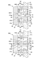
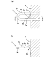
- (A) is a sectional view taken along line VIIa-VIIa in FIG. 6 (a)
- (a) is a sectional view taken along line VIIb-VIIb in FIG. 6 (b).
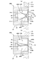
- Open / closed body perspective view (A) of the insert holding means is a transverse cross-sectional view of the opening / closing body when passing the fastening portion, and (b) is a transverse sectional view after the fastening portion is inserted.
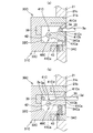
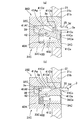
- (A) of the insert holding means provided with the opening / closing means of another configuration is a cross-sectional view when the fastening portion passes through the opening / closing body, and (b) is a cross-sectional view after the fastening portion is inserted.
- (A) of the insert holding means provided with the opening / closing means of another configuration is a cross-sectional view when the fastening portion passes through the opening / closing body, and (b) is a cross-sectional view after the fastening portion is inserted.
- (A) of the insert holding means provided with the opening / closing means of another configuration is a cross-sectional view when the fastening portion passes through the opening / closing body, and (b) is a cross-sectional view after the fastening portion is inserted.
- (A) of the insert holding means provided with the opening / closing means of another configuration is a cross-sectional view when the fastening portion passes through the opening / closing body, and (b) is a cross-sectional view after the fastening portion is inserted.
- (A) is a sectional view taken along line XIV-XIV in FIG. 1, and (b) is a sectional view taken along line bb in FIG. 14 (a).
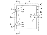
- the molded product 1 includes an insert member 4 having an anchor member 2 and a plurality of fastening members 3 attached to the anchor member 2, and a polyolefin-based foamed resin in which the insert member 4 is integrally molded.
- the insert member 4 is foam-molded in the mold so that at least the projecting portion 3a of the front end side portion of the fastening member 3 protrudes from the foam molded body 5 to the outside in the mold opening / closing direction at the time of molding. Is formed integrally with the foamed molded body 5 in an embedded state.
- FIG. 1 is a perspective view of a vehicle sheet core material as a molded product 1 in a vertically placed state.
- a vehicle sheet 6 has a molded product 7 made of polyurethane on an upper side of a foam molded product 5 of the molded product 1. As shown by an imaginary line, it is integrally formed and covered with a cover member.
- the mold according to the present invention is a molded product 1 in which the insert member 4 having the protruding portion 3a is integrally formed with the foamed molded body 5, the vehicle bumper core material in addition to the vehicle sheet core material.
- automobile interior members such as a headrest core material, or a molded product 1 having any other configuration can be manufactured.
- parts other than the protrusion part 3a among the insert members 4 correspond to an embedding part.
- the anchor material 2 is formed by bending a metal wire made of iron or stainless steel into a rectangular frame shape and welding both ends thereof.
- a pair of mounting plates 8 are fixed to one anchor side portion 2a of the pair of parallel anchor side portions 2a and 2b of the anchor member 2 with a space between each other, and the other anchor side portion 2b
- One attachment plate 8 is fixed at the center, and these three attachment plates 8 are provided in an embedded shape in the foamed molded body 5.
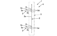
- a fastening member 3 is attached to the mounting plate 8 so as to protrude outward (in the front of the sheet of FIG. 2 and below in the assembled state to the vehicle body).
- the arrangement position and the number of the mounting plate 8 and the fastening member 3 can be arbitrarily set.
- the anchor material 2 a material having an arbitrary configuration can be adopted as long as the fastening member 3 can be fixed to the foamed molded body 5.
- an elongated pipe-shaped or bar-shaped member made of a metal material or a synthetic resin material is used which is configured in a frame shape, a straight line shape, or a lattice shape according to the sheet shape, or made of a metal material or a synthetic resin material. It can be composed of a plate-like member such as a square or a rectangle.
- the fastening member 3 is fixed to the anchor member 2 via the mounting plate 8, the fastening member 3 can be directly fixed to the anchor member 2.
- the fastening member 3 has a fixing part 3b to the mounting plate 8 and a fastening part 3c protruding outward from the fixing part 3b.
- the fastening part 3c has a pair of base ends connected to the fixing part 3b. This is composed of a substantially U-shaped female hook having a leg portion 3d and a connecting portion 3e for connecting the distal end portion of the leg portion 3d.
- the base end side portion of the fastening portion 3c and the fixing portion 3b are embedded in the foam molded body 5, and the distal end side portion of the fastening portion 3c projects from the foam molded body 5 to the outside in the mold opening / closing direction during molding. Projections 3 a are formed, and the molded product 1 is configured to be assembled to the vehicle body by connecting the vehicle-side members to the projections 3 a of these three fastening members 3.
- the number and arrangement positions of the fastening members 3 can be arbitrarily set according to the configuration on the vehicle side. Further, the protruding portion 3a of the fastening member 3 that protrudes from the foamed molded body 5 to the outside in the mold opening / closing direction at the time of molding is used for fixing the molded product 1 or connecting other products to the molded product 1. In addition, any shape can be adopted as long as the cross-sectional area of the base end portion is configured to be smaller than the projected area in the mold opening / closing direction.
- the fastening portion 3c is configured by a hook portion formed of a female hook such as a U-shape or a V-shape, or a male hook such as a J-shape or an L-shape, or a bolt head on the tip side. It can be constituted by an arranged bolt or an eyebolt having an eye at the tip. More specifically, like the fastening member 3 shown in FIG. 4 (a), a member having a fixing portion 3b for the mounting plate 8 and a fastening portion 3c made of a U-shaped female hook may be adopted. As shown in FIG.
- a fastening member 3A having a fixing part 3Ab for the mounting plate 8 and a fastening part 3Ac made of a rectangular female hook may be adopted, or a fastening member shown in FIG. 4 (c).
- a fixing member 3Bb with respect to the mounting plate 8 and a fastening portion 3Bc made of a semi-elliptical female hook are adopted, or a fastening member 3C shown in FIG.
- the fixing member 3Gb includes a fixing portion 3Gb including a nut member fixed to the mounting plate 8 and a fixing portion 3Gc including an eyebolt whose tip is screwed to the nut member. Can be used.
- a projection 5a protruding outward from the surface of the foam molded body 5 is foamed on the projection surface of the projection 3a of the fastening member 3 in the mold opening / closing direction with respect to the surface of the foam molded body 5.
- the molded body 5 is integrally formed.
- the projection 5a includes a base portion 5b formed by the inner surface of the insertion hole 35 provided in the mold apparatus for molding the molded product 1, and an insertion / release operation surface 41c of the opening / closing means 40, 41A to 41C.
- the shape of the base portion 5b of the protruding portion 5a is formed according to the shape of the inner surface of the insertion hole 35 through which the protruding portion 3a can be inserted, and the shape of the raised portion 5c is the same as that of the insertion / release operation surfaces 41c and 41Cc. It is formed in a substantially linear shape with a cross-sectional shape adapted to the shape.
- the foamed molded body 5 is configured as a thick rectangular plate having a size suitable for a vehicle seat. However, the size and shape of the foamed molded body 5 can be configured in an appropriate shape according to the size and shape of the vehicle seat.
- the polyolefin resin constituting the foamed molded product 5 is a polymer containing 75% by weight or more of an olefin monomer.
- olefin resin Polyolefin resin
- olefin monomer examples include, for example, ethylene, propylene, butene-1, isobutene, pentene-1, 3-methyl-butene-1, hexene-1, 4-methyl-pentene-1, 3,4 And ⁇ -olefins having 2 to 12 carbon atoms such as dimethyl-butene-1, heptene-1, 3-methyl-hexene-1, octene-1, and decene-1. These may be used alone or in combination of two or more.
- olefinic monomer examples include, for example, cyclopentene, norbornene, 1,4,5,8-dimethano-1,2,3,4,4a. , 8,8a, 6-octahydronaphthalene, and the like, 5-methylene-2-norbornene, 5-ethylidene-2-norbornene, 1,4-hexadiene, methyl-1,4-hexadiene, 7-methyl-1 , 6-octadiene and the like. These may be used alone or in combination of two or more.
- the polypropylene resin is not particularly limited as long as it contains propylene as the main component of the monomer.
- propylene homopolymer ⁇ -olefin-propylene random copolymer, ⁇ -olefin-propylene block copolymer Etc. These may be used alone or in combination of two or more.
- the ⁇ -olefin is ethylene
- a polypropylene resin containing ethylene as a comonomer component is easy to obtain and excellent in process moldability, and therefore can be used for in-mold foam molding.
- the polypropylene resin is not particularly limited as long as it contains propylene as a main component of the monomer, and examples thereof include a propylene homopolymer, an olefin-propylene random copolymer, and an olefin-propylene block copolymer. . These may be used alone or in combination of two or more.
- Examples of the polyethylene resin used in the present invention include ethylene homopolymer, ethylene- ⁇ -olefin random copolymer, ethylene- ⁇ -olefin block copolymer, low density polyethylene, high density polyethylene, and linear low density polyethylene. Is mentioned.
- Examples of the ⁇ -olefin mentioned here include ⁇ -olefins having 3 to 15 carbon atoms, and these may be used alone or in combination of two or more.
- good foaming properties are obtained when the ethylene- ⁇ -olefin block copolymer has a comonomer content other than ethylene of 1 to 10% by weight or is a linear low density polyethylene. And can be suitably used for in-mold foam molding.
- the polyolefin-based resin used in the present invention further includes a cell nucleating agent such as talc, an antioxidant, a metal deactivator, a phosphorus-based processing stabilizer, an ultraviolet absorber, an ultraviolet stabilizer, and a fluorescence as necessary.
- Brighteners, stabilizers such as metal soaps, or crosslinking agents, chain transfer agents, lubricants, plasticizers, fillers, reinforcing agents, inorganic pigments, organic pigments, conductivity improvers, flame retardant improvers, interfaces It can be used as a polyolefin resin composition to which an additive such as an activator type or a polymer type antistatic agent is added.
- the polyolefin resin composition used in the present invention is usually melted with an additive, if necessary, with a polyolefin resin in advance using an extruder, kneader, Banbury mixer, roll, etc. so as to be easily used for pre-foaming.
- the mixture is mixed and molded into a polyolefin resin particle having a desired particle shape such as a cylindrical shape, an elliptical shape, a spherical shape, a cubic shape, a rectangular parallelepiped shape, or the like.
- the method for producing the polyolefin resin pre-expanded beads used in the present invention is not particularly limited, but the polyolefin resin particles are dispersed in a dispersion medium in the presence of a foaming agent in a dispersion medium in the presence of a foaming agent.
- the heating temperature in the sealed container is preferably the melting point of the polyolefin resin particles ⁇ 25 ° C. or higher and the melting point of the polyolefin resin particles + 25 ° C. or lower, more preferably the melting point of the polyolefin resin particles ⁇ 15 ° C. or higher and the melting point of the polyolefin resin particles +15.
- the temperature is in the range of °C or less.
- the blowing agent is not particularly limited.
- aliphatic hydrocarbons such as propane, isobutane, normal butane, isopentane, and normal pentane
- inorganic gases such as air, nitrogen, and carbon dioxide
- Water or the like and a mixture thereof can be used.
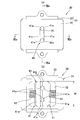
- the mold apparatus M for in-mold foam molding includes a concave unit 10 having a concave mold 11 and a concave housing 12 that holds the concave mold 11, a convex mold 21, and a convex housing 22 that holds the concave mold. And the three insert holding means 30 for fixing and holding the insert member 4 between the concave unit 10 and the convex unit 20.
- the insert holding means 30 fixes and holds the insert member 4 to the convex unit 20.
- the concave unit 10 and the convex unit 20 are combined, and the cavity CA is fixedly held in the cavity CA formed by the concave mold 11 and the convex mold 21 as a mold.
- the foamable resin particles are filled in, and the foamable resin particles are heated and foam-fused in the cavity CA, and the insert portion is formed in the foamed molded body 5. 4 is obtained without to obtain a molded article 1 which is integrally formed in buried form a.
- the mold composed of the concave mold 11 and the convex mold 21 is made of a material having a low specific heat and high thermal conductivity, for example, a casting made of an aluminum alloy so that the molded product 1 can be smoothly heated and cooled.
- , 22 are made of iron-based metal in order to reduce the manufacturing cost of the mold apparatus M and to ensure sufficient strength and rigidity.
- the concave housing 12 includes a rectangular cylindrical concave frame 13, and a concave mold 11 fixed to the concave frame 13 via a center plate 14 so as to close an opening on the front side of the concave frame 13 (the mold mating surface side). And a concave back plate 15 for closing the opening on the back side of the concave frame 13, and a concave chamber 16 is formed in the concave housing 12 on the back side of the concave mold 11.
- the concave unit 10 is connected to a steam supply pipe 18a, a cooling water supply pipe 18b, and a drain pipe 18c that open into the concave chamber 16, and control valves 19a to 19c interposed in the middle of these pipes 18a to 18c.
- steam is supplied into the concave chamber 16 to heat and foam the foamable resin particles, or cooling water is sprayed from the nozzle 18d to the back side of the concave mold 11 to cool the molded product 1 or unnecessary drainage. Or the like can be discharged from the concave chamber 16.
- the concave mold 11 is formed with a large number of vent holes 11a through which vapor can be supplied from the concave chamber 16 into the cavity CA.
- a filler 17 is fixed to the concave back plate 15, and the tip of the filler 17 is inserted into the cavity CA through the concave mold 11, and the expandable resin particles are supplied from the filler 17 into the cavity CA,
- the cavity CA is configured to be filled.
- a raw material hopper for filling the pre-expanded beads into the cavity CA and a raw material hose for connecting the raw material hopper and the filling machine are not shown, they are arranged in the same manner as a mold having a general configuration.
- the convex housing 22 is fixed to the convex frame 23 via the center plate 24 so as to close the rectangular cylindrical convex frame 23 and the opening on the front side of the convex frame 23 (the mating surface side of the mold). And a convex back plate 25 that closes the opening on the back side of the convex frame 23, and a convex chamber 26 (this is a steam chamber) in the convex housing 22 on the back side of the convex mold 21. Corresponding to) is formed.
- the convex unit 20 is connected to a steam supply pipe 28a, a cooling water supply pipe 28b, and a drain pipe 28c that open into the convex chamber 26, and control valves 29a to 29a interposed in the middle of these pipes 28a to 28c.
- 29c steam is supplied into the convex chamber 26 to heat and foam the expandable resin particles, or cooling water is sprayed from the nozzle 28d to the back side of the convex mold 21 to cool the molded product 1 Further, unnecessary drain can be discharged from the convex chamber 26.
- a large number of vent holes 21a are formed in the convex mold 21, and steam is supplied from the convex chamber 26 into the cavity CA through the vent holes 21a.
- the present invention is characterized by the insert holding means 30, and any other known configuration other than that illustrated in FIG. 5 can be adopted as the configuration of the mold apparatus M other than that.
- the filling device 17 is provided on the concave mold 11 side, or an ejector pin that can protrude into the cavity CA is provided on the concave mold 11 or the convex mold 21.
- the insert holding means 30 includes a casing 31, opening / closing means 40 provided in the casing 31, and a heat-resistant permanent magnet 39 provided in the bottom surface portion 31 a of the casing 31, and corresponds to the position where the insert member 4 is disposed. Thus, it is assembled in a mounting hole 21 b provided in the convex mold 21. However, depending on the configuration of the molded product 1, it is possible to provide an attachment hole in the concave mold 11 and assemble the insert holding means 30 to this.
- the permanent magnet 39 is preferably provided, but may be omitted.
- the casing 31 includes a main body portion 33 having an accommodation recess 32 capable of accommodating the protrusion 3 a of the fastening member 3, and a lid member 34 attached to the main body portion 33 so as to close the opening of the accommodation recess 32.
- the 34 side is set to the cavity CA side, and the casing 31 side is set to the convex chamber 26 side.
- a molding surface 21c facing the cavity CA is formed on the front surface of the lid member 34 so as to be flush with the molding surface 21c of the convex mold 21 without any step, and a projection 3a of the fastening portion 3c is formed at the center of the front surface of the lid member 34. Is formed into a long and narrow insertion hole 35 that can be inserted without any gap.
- a heat-resistant permanent magnet 39 is assembled to the bottom surface portion 31 a of the casing 31, and the protrusions 3 a of the three fastening members 3 of the insert member 4 are attached to the three insert holding means 30 in order to attach the insert member 4 to the convex mold 21.
- the insertion holes 35 are inserted into the insertion holes 35, the tip portions of the retaining portions 3 c are attracted and held by the permanent magnets 39, and the insert member 4 is fixed and held at an appropriate position of the convex mold 21.
- the opening / closing means 40 prevents the pre-expanded beads from entering the insertion hole 35 in a state where the protruding portion 3a is inserted into the insertion hole 35, and the pre-expanded beads are inserted into the gap. Any structure can be adopted as long as it can prevent the occurrence of burrs due to intrusion. However, it is preferable to completely eliminate the gap. However, in the case where generation of burrs of an inconspicuous degree is allowed, the insertion hole 35 with the protruding portion 3a inserted in a range in which the pre-foamed beads cannot pass through. It is also possible to configure so that a slight gap is formed.
- the opening / closing means 40 is housed in the housing recess 32 of the main body 33 and is arranged so as to be positioned on both sides of the protrusion 3 a when the protrusion 3 a of the insert member 4 is inserted into the insert holding means 30.
- a pair of opening / closing bodies 41 and a pair of support shafts that respectively support the pair of opening / closing bodies 41 so as to be rotatable over an open position illustrated in FIG. 9A and a closed position illustrated in FIG. 9B. 42 and a pair of urging means 43 that constantly urge the pair of opening / closing bodies 41 toward the closed position.
- the insert holding means 30 can be made of any material such as aluminum, brass, stainless steel, or heat-resistant synthetic resin.
- the casing 31 is made of brass or aluminum
- the opening / closing body 41 is made of brass or aluminum
- the support shaft 42 is made of stainless steel or brass having high strength and corrosion resistance.
- the pair of support shafts 42 are provided on the main body portion 33 so as to extend in the vertical direction slightly inward from the central portion of the housing recess 32 in a substantially parallel manner with a space therebetween.
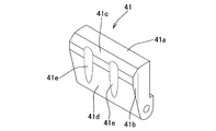
- the opening / closing body 41 has a base end portion rotatably supported by the support shaft 42, a distal end portion extending to the lid member 34, and the opening / closing body 41 having an insertion hole 35 vertically divided at the closed position.
- a closed surface 41 a capable of closing the half on one side is formed, and the closed surface 41 a is formed by an arc surface centered on the support shaft 42.
- a pair of arcuate surfaces 34 a centering on the support shaft 42 of the corresponding opening / closing body 41 is recessed on the facing surface of the lid member 34 facing the closing surface 41 a of the pair of opening / closing bodies 41.
- the pair of opening and closing bodies 41 can close the insertion hole 35 without any gap.
- the closing surface 41a is preferably slidably contacted with the lid member 34 without any gaps, but is disposed apart from the lid member 34 with a gap to the extent that no burrs are generated. Is also possible.
- An operation protrusion 41b having a height larger than the radius of the leg 3d of the protrusion 3a is formed on the front end portion of the facing portion of the pair of opening / closing bodies 41, and the front end portion of the operation protrusion 41b is
- an insertion / opening operation surface 41c (which is an insertion-side opening operation portion) is formed of an inclined surface that contacts the tip of the protruding portion 3a and operates the opening / closing body 41 to the open position.
- a sampling / opening operation surface 41d (which corresponds to a sampling-side opening operation portion) formed of an inclined surface to be operated is formed.
- the width of the opening / closing body 41 is configured so that the insertion hole 35 is wider than the length of the insertion hole, and a pair of leg portions 3d of the projecting portion 3a is fitted in the middle portion of the facing portion of the pair of opening / closing bodies 41 in the width direction.
- a pair of semi-cylindrical fitting grooves 41e are formed.
- the width W of the opening / closing body 41 is set to the same length as the center-to-center distance of the pair of leg portions 3d, and is 1/4 cylindrical at both ends in the width direction of the facing portions of the pair of opening / closing bodies 41. It is also possible to form a pair of fitting grooves. Further, if the occurrence of some burrs is allowed, the width of the opening / closing body 41 can be made slightly narrower than the distance between the centers of the pair of leg portions 3d.
- the opening / closing body 41 has a closing surface 41a, an insertion / opening operation surface 41c, and a withdrawal / opening operation surface 41d, the shape of the facing portion of the pair of opening / closing bodies 41 is narrow on the base end side. It is also possible to configure a trapezoidal shape, a home base shape, a triangular shape, or a T shape.
- the biasing means 43 can be constituted by a compression coil spring as in the present embodiment, or can be a tension coil spring or a leaf spring. It is also possible to configure with these.
- a bead discharge hole 44 that opens into the convex chamber 26 is provided on the bottom surface 31 a of the main body 33 or the bottom surface 31 a of the side wall.
- the bead discharge hole 44 is set to a size through which the pre-expanded beads can pass, and even when the pre-expanded beads enter the housing recess 32 when the pre-expanded beads are filled into the cavity CA, Since the pre-expanded beads can be discharged into the convex chamber 26 through the bead discharge hole 44, the occurrence of burrs due to the entry of the pre-expanded beads into the receiving recess 32 can be prevented, and the pre-expanded beads are stored in the receiving recess.
- the appropriate value of the size of the bead discharge hole 44 varies depending on the size of the pre-expanded beads to be used. However, since the maximum size of the pre-expanded beads generally used is about 5 mm, it is preferably set to 5 mm or more. In order to make the insert holding means 30 small, it is preferable to set it to 10 mm or less.
- the mold is closed until the convex mold 21 and the concave mold 11 are slightly opened and the pre-expanded beads do not jump out of the cavity.
- the cavity CA is filled with polyolefin resin pre-expanded beads whose air pressure is increased to 0.15 Mpa (G) at the maximum.
- water vapor is alternately passed through the concave chamber 16 and the convex chamber 26, and in the heat-sealing stage, if the polyethylene-based resin is used, the polypropylene-based resin is up to about 0.1 Mpa (G). If so, the vapor pressure is increased to about 0.2 to 0.4 Mpa (G), and the vapor pressure is maintained for 3 to 30 seconds.
- the internal pressure application method for increasing the air pressure in the pre-expanded beads has been exemplified in advance. Is not necessary, and foaming power may be imparted to the pre-expanded beads using another method.
- the pair of opening / closing bodies 41 are rotated to the open position side so that the protruding portion 3a can be extracted from the accommodating recess 32, and when the protruding portion 3a is extracted from the accommodating recess 32, the pair of opening / closing bodies 41 is The urging force of the urging means 43 returns to the closed position.
- the opening / closing means 40 is linked with the insertion operation.
- the opening and closing body 41 closes the cavity CA-side opening, and the gap between the opening of the cavity CA-side opening and the outer peripheral portion of the base of the projecting portion 3a is blocked.
- flash around the protrusion part 3a of the goods 1 can be prevented reliably.
- the insertion hole 35 and the opening / closing means 40 are inserted and opened operation surface 41 c, as shown in FIG. 14, from the base portion 5 b and the raised portion 5 c.
- the protrusion 5a having a beautiful surface is continuously formed between the base portions of both the leg portions 3d of the projecting portion 3c, and burrs are formed around the leg portions as in a conventional in-mold foam-molded product. As a result, the appearance of the in-mold foam-molded product can be reduced, and the problem that the burr is dropped from the in-mold foam-molded product can be effectively prevented.
- the opening and closing means 40 opens and closes the cavity CA side opening of the housing recess 32 in conjunction with the insertion operation and the extraction operation of the protruding portion 3a with respect to the housing recess 32, thereby reducing the workability of the molding operation. Therefore, the occurrence of burrs around the protrusion 3a can be prevented, the work for the burrs trim becomes unnecessary, the productivity can be improved and the labor cost can be reduced.
- the pair of opening / closing bodies 41 are always urged toward the closed position, but the opening / closing bodies 41A are always opened like the opening / closing means 40A of the insert holding means 30A shown in FIG. It can also be configured to be biased.
- the opening / closing body 41A of the opening / closing means 40A will be described only with respect to the difference from the opening / closing body 41.
- an extension 41Af extending from the support shaft 42 to the vicinity of the bottom surface 31a of the main body 33 is provided.
- a closing operation surface 41Ag (which corresponds to a closing operation portion) is inclined so that the bottom surface portion 31a side approaches each other at the open position illustrated in FIG. Is formed).
- urging means 43A for constantly urging the opening / closing body 41A toward the open position is provided, and until the protrusion 3a is inserted into the housing recess 32, the urging means 43A is provided.
- the opening / closing body 41 is held in the open position by the urging force, the protruding portion 3a is inserted into the receiving recess 32, and the connecting portion 3e of the protruding portion 3a is inserted between the closing operation surfaces 41Ag, as shown in FIG.
- the opening / closing body 41A rotates to the closing position side, and the protruding portion 3a is inserted until it comes into contact with the permanent magnet 39.
- the portion 3a is attracted and held by the permanent magnet 39, and the opening / closing body 41A is held at the closed position.
- the protruding portion 3a is operated in the extraction direction from the accommodating recess 32, the opening / closing body 41A is rotated to the open position by the urging force of the urging means 43A, the insertion hole 35 is opened, and the protruding portion 3a is removed from the accommodating recess 32. Can be extracted.
- the urging means 43A can be constituted by a compression coil spring as long as it always urges the pair of opening / closing bodies 41A to the open position side, or a tension coil spring or a leaf spring. It is also possible to configure with these.
- the opening / closing body 41A is always urged toward the open position by the urging means 43A, so that the insertion / release operation surface 41c and the extraction / release operation surface 41d can be omitted. For this reason, since the dent exposed to the cavity CA side by the insertion / opening operation surface 41c is eliminated while the opening / closing body 41A is closed, the generation of burrs near the protrusion 3a can be more effectively prevented.
- the biasing means 43A is omitted, and a braking means is provided for applying an operating resistance to the turning operation of the opening / closing body 41A by friction or the like, and when the protruding portion 3a is extracted from the accommodating recess 32, the connecting portion of the protruding portion 3a
- the opening / closing body 41A is operated to the open position, the opening / closing body 41A is held in the open position by the braking means, and the protrusion 3a is inserted into the receiving recess 32, the protrusion 3a
- the closing operation surface 41Ag is operated outward by the connecting portion 3e and the opening / closing body 41A is operated to the closing position.
- the opening / closing body 41 and the biasing means 43 are formed as separate members. However, like the opening / closing means 40B of the insert holding means 30B shown in FIG. By using it, the opening / closing body 41 and the urging means 43 can be integrated, the support shaft 42 can be omitted, and the number of parts can be reduced.
- the opening / closing means 40B will be described.
- a pair of opening / closing bodies 41B made of leaf springs are provided facing the insertion position of the protrusion 3a with respect to the housing recess 32, and the opposing surfaces of the pair of opening / closing bodies 41B As with the opening / closing body 41, an insertion / opening operation surface 41c, a withdrawal / opening operation surface 41d, and a pair of fitting grooves 41e are formed, and the end of the opening / closing body 41B on the insertion hole 35 side is at the end of the casing 31.
- a fixed displacement promoting portion 41Bh is continuously provided.
- the opening / closing means 40B when the protruding portion 3a is inserted into the rear of the housing, the insertion / opening operation surface 41c is pushed by the protruding portion 3a, and the opening / closing body 41B is operated to the open position side shown in FIG. However, when the protruding portion 3a is inserted and the connecting portion 3e of the protruding portion 3a passes through the opening / closing body 41B, the opening / closing body 41B returns to the closed position illustrated in FIG. 11B by the biasing force of the opening / closing body 41B. Become.
- the extraction / release operation surface 41d is operated laterally by the connecting portion 3e of the protrusion 3a, and the protrusion 3a is opened and closed. It will be extracted from between 41B.
- the opening / closing body 41B any configuration other than the facing portion of the pair of opening / closing bodies 41B can be used as long as the facing portion can be switched between the open position and the closing position by elastic deformation of the opening / closing body 41B.
- the insertion hole 35 side is fixed to the casing 31, but the bottom surface portion 31a side can also be fixed to the casing 31.
- the opening / closing means 40C will be described.
- the opening / closing body 41C is disposed on one side of the projecting portion 3a inserted into the housing recess 32C of the casing 31C, and its base end portion is rotatably supported by the support shaft 42. The portion extends to the lid member 34.
- a closing surface 41Ca having a size capable of closing the insertion hole 35 at the closing position is formed at the distal end portion of the opening / closing body 41C, and the closing surface 41Ca is formed by an arc surface centering on the support shaft 42.
- An arc surface 34Ca centering on the support shaft 42 is formed on the facing surface of the lid member 34C facing the closing surface 41Ca, and a gap between the closing surface 41Ca of the opening / closing body 41C and the corresponding arc surface 34Ca of the lid member 34C is formed.
- the insertion hole 35 can be closed with substantially no gap by the opening / closing body 41C.
- An operation projection 41Cb having a height larger than the diameter of the leg portion 3d is formed in a protruding shape on the tip side portion of the side surface of the opening / closing body 41C on the side of the projection 3a inserted into the housing recess 32C, and the tip of the operation projection 41Cb In the side portion, when the protruding portion 3a is inserted into the accommodating recess 32C, an insertion / opening operation surface 41Cc (which is an insertion surface) is formed of an inclined surface that contacts the tip of the protruding portion 3a and operates the opening / closing body 41C to the open position.
- a sampling / opening operation surface 41 ⁇ / b> Cd is formed which is an inclined surface for operating to the open position.
- a pair of fitting grooves 41Ce deeper than the diameter of the leg portion 3d into which the pair of leg portions 3d are fitted are formed in the middle portion in the width direction of the operation protrusion 41Cb.
- the width of the opening / closing body 41C is set to the same length as the distance between the centers of the pair of leg portions 3d as in the above-described embodiment, and 1/4 cylinders are formed at both ends in the width direction of the opening / closing body. It is also possible to form a pair of fitting grooves. Further, if the occurrence of some burrs is allowed, the width of the opening / closing body can be configured to be slightly narrower than the distance between the centers of the pair of leg portions 3d.
- the opening / closing body 41C of the opening / closing means 40C is always held at the closed position by the urging means 43, and when the protrusion 3a is inserted into the insertion hole 35, the protrusion The connecting portion 3e of 3a abuts on the insertion / opening operation surface 41Cc, the opening / closing body 41C is operated to the open position, the protruding portion 3a is inserted into the accommodating recess 32C, and the connecting portion 3e of the protruding portion 3a is connected to the permanent magnet 39. Adsorption is held.
- the connecting portion 3e of the protruding portion 3a contacts the extraction / opening operation surface 41Cd, the opening / closing body 41C is operated to the open position, and the protruding portion 3a is extracted from the accommodating recess 32C.
- the opening / closing body 41C is rotated to the closed position by the biasing means 43.
- the opening / closing means 40A, 40B can be provided with only one opening / closing body 41A, 41B in the same manner as the opening / closing means 40C.
- the opening / closing body 41A is always urged toward the open position like the opening / closing means 40A
- the extension 41Af is formed at the base end portion of the opening / closing body 41C and the closing operation surface 41Ag is formed similarly to the opening / closing body 41A, and the protruding portion 3a is inserted into the receiving recess 32C, the connecting portion 3e of the protruding portion 3a is closed.
- the opening / closing body 41D When the opening / closing body 41D is brought into contact with the operation surface 41Ag and rotated to the closing position shown in FIG. 13B, the insertion hole 35 is closed, and the protruding portion 3a is extracted from the housing recess 32C, FIG. As shown, the opening / closing body 41D is rotated to the open position by the biasing means 43A, and the insertion hole 35 is opened.
- any means can be used as long as the protrusion 3a can be inserted into and removed from the housing recess 32 and the insertion hole 35 can be closed while the protrusion 3a is inserted into the housing recess 32.
- an opening / closing body slidable in a direction orthogonal to the insertion direction of the protruding portion 3a is provided, and the insertion hole 35 can be opened / closed by a sliding operation of the opening / closing body.
Abstract
Description
先ず、本発明に係る金型にて成形可能な成形品の構成について説明する。 Hereinafter, embodiments of the present invention will be described with reference to the drawings.
First, the structure of a molded product that can be molded with the mold according to the present invention will be described.
図1~図3に示すように、成形品1は、アンカー材2と、アンカー材2に付設した複数の留め部材3とを有するインサート部材4と、インサート部材4を一体成形したポリオレフィン系発泡樹脂からなる発泡成形体5とを備え、少なくとも留め部材3の先端側部分の突出部3aが発泡成形体5から成形時の型開閉方向の外部へ突出するように、インサート部材4を型内発泡成形により発泡成形体5に埋設状に一体成形したものである。図1は、成形品1としての車輛用シート芯材を縦置きにした状態での斜視図で、車輛用シート6は、成形品1の発泡成形体5の上側にポリウレタンからなる成形体7を仮想線で示すように一体成形し、これをカバー部材で被覆することで製作される。ただし、本発明に係る金型は、突出部3aを有するインサート部材4を発泡成形体5に一体成形してなる成形品1であれば、車輛用シート芯材以外に、車輛用のバンパー芯材や、ヘッドレスト芯材などの自動車内装部材や、それ以外の任意の構成の成形品1を製作できる。なお、この成形品1では、インサート部材4のうちの突出部3a以外の部分が埋設部に相当する。 (Molding)
As shown in FIGS. 1 to 3, the molded
オレフィン系単量体の具体例としては、例えば、エチレン、プロピレン、ブテン-1、イソブテン、ペンテン-1、3-メチル-ブテン-1、ヘキセン-1、4-メチル-ペンテン-1、3,4-ジメチル-ブテン-1、へプテン-1、3-メチル-ヘキセン-1、オクテン-1、デセン-1などの炭素数2~12のα-オレフィンなどがあげられる。これらは単独で用いてもよく2種以上を組み合わせて用いてもよい。 (Polyolefin resin)
Specific examples of the olefin monomer include, for example, ethylene, propylene, butene-1, isobutene, pentene-1, 3-methyl-butene-1, hexene-1, 4-methyl-pentene-1, 3,4 And α-olefins having 2 to 12 carbon atoms such as dimethyl-butene-1, heptene-1, 3-methyl-hexene-1, octene-1, and decene-1. These may be used alone or in combination of two or more.
次に、金型装置の構成の一例について説明する。
図5に示すように、型内発泡成形用金型装置Mは、凹型11とそれを保持する凹型ハウジング12とを有する凹型ユニット10と、凸型21とそれを保持する凸型ハウジング22とを有する凸型ユニット20と、凹型ユニット10と凸型ユニット20間にインサート部材4を固定保持する3つのインサート保持手段30とを備え、インサート保持手段30により凸型ユニット20にインサート部材4を固定保持して、凹型ユニット10と凸型ユニット20とを組み合わせ、金型としての凹型11と凸型21とで形成されるキャビティCA内にインサート部材4の埋設部分を固定保持した状態で、該キャビティCA内に発泡性樹脂粒子を充填し、キャビティCA内において発泡性樹脂粒子を加熱、発泡融着させて、発泡成形体5にインサート部材4を埋設状に一体成形した成形品1を得るようになしたものである。 (Molding equipment)
Next, an example of the configuration of the mold apparatus will be described.
As shown in FIG. 5, the mold apparatus M for in-mold foam molding includes a
インサート保持手段30は、ケーシング31と、ケーシング31に内装した開閉手段40と、ケーシング31の底面部31a内に設けた耐熱性を有する永久磁石39とを備え、インサート部材4の配設位置に対応させて凸型21に設けた取付孔21bに組み付けられている。ただし、成形品1の構成によっては、凹型11に取付孔を設け、これにインサート保持手段30を組付けることも可能である。また、永久磁石39は、設けることが好ましいが省略することも可能である。 (Insert holding means)
The insert holding means 30 includes a
この金型装置Mを用いて成形品1を製作する際には、先ず、セット工程において、凹型11と凸型21を型開きした状態で、インサート部材4の3つの突出部3aをインサート保持手段30の挿通孔35に挿入して、インサート部材4を金型装置Mにセットする。このとき、図9(a)に示すように、開閉手段40の1対の開閉体41の挿入開放操作面41cが突出部3aの先端部で押されて、1対の開閉体41が付勢手段43の付勢力に抗して開放位置側へ回動し、その後突出部3aの連結部3eが開閉体41を通過すると、図9(b)に示すように、付勢手段43の付勢力により開閉体41が閉塞位置に回動し、開閉体41の1対の嵌合溝41eが突出部3aの1対の脚部3dに略隙間なくそれぞれ嵌合して、1対の開閉体41の先端の閉塞面41aで挿通孔35が略隙間なく全面的に閉塞されるとともに、突出部3aの先端部が永久磁石39に吸着保持されて、インサート部材4が3点で凸型21に位置決め保持される。 (Manufacturing method of in-mold foam molded product)
When the molded
ここでは、予備発泡ビーズの発泡力を高めるための方法として、予め予備発泡ビーズ内の空気圧力を高める内圧付与法を例示したが、十分な発泡力を有する予備発泡ビーズであれば、内圧付与操作は不要であるし、別の方法を用いて予備発泡ビーズに発泡力を付与してもよい。 Next, in the molding process, the mold is closed until the
Here, as an example of the method for increasing the foaming power of the pre-expanded beads, the internal pressure application method for increasing the air pressure in the pre-expanded beads has been exemplified in advance. Is not necessary, and foaming power may be imparted to the pre-expanded beads using another method.
2a アンカー側部 2b アンカー側部
3 留め部材 3a 突出部
3b 固定部 3c 留め部
3d 脚部 3e 連結部
4 インサート部材 5 発泡成形体
5a 突起部 5b 土台部
5c 隆起部
6 車輛用シート 7 成形体
8 取付板
3A 留め部材 3Ab 固定部
3Ac 留め部
3B 留め部材 3Bb 固定部
3Bc 留め部
3C 留め部材 3Cb 固定部
3Cc 留め部
3D 留め部材 3Db 固定部
3Dc 留め部
3E 留め部材 3Eb 固定部
3Ec 留め部
3F 留め部材 3Fb 固定部
3Fc 留め部
3G 留め部材 3Gb 固定部
3Gc 留め部
CA キャビティ M 金型装置
10 凹型ユニット 11 凹型
11a 通気孔 12 凹型ハウジング
13 凹型フレーム 14 センタープレート
15 凹型背面板 16 凹型チャンバ
17 充填器 18a 蒸気供給管
18b 冷却水供給管 18c ドレン管
18d ノズル 19a-19c 制御弁
20 凸型ユニット 21 凸型
21a 通気孔 21b 取付孔
21c 成形面 22 凸型ハウジング
23 凸型フレーム 24 センタープレート
25 凸型背面板 26 凸型チャンバ
28a 気供給管 28b 冷却水供給管
28c ドレン管 28d ノズル
29a-29c 制御弁
30 インサート保持手段
31 ケーシング 31a 底面部
32 収容凹部 33 本体部
34 蓋部材 34a 円弧面
35 挿通孔 39 永久磁石
40 開閉手段 41 開閉体
41a 閉塞面 41b 操作突部
41c 挿入開放操作面 41d 抜取開放操作面
41e 嵌合溝 42 支軸
43 付勢手段 44 ビーズ排出孔
30A インサート保持手段 40A 開閉手段
41A 開閉体 41Af 延長部
41Ag 閉塞操作面 43A 付勢手段
30B インサート保持手段 40B 開閉手段
41B 開閉体 41Bh 変位促進部
30C インサート保持手段 31C ケーシング
32C 収容凹部 33C 本体部
34C 蓋部材 34Ca 円弧面
40C 開閉手段 41C 開閉体
41Ca 閉塞面 41Cb 操作突部
41Cc 挿入開放操作面 41Cd 抜取開放操作面
41Ce 嵌合溝
30D インサート保持手段 4D 開閉手段
41D 開閉体 DESCRIPTION OF SYMBOLS 1 Molded product 2 Anchor material 2a Anchor side part 2b Anchor side part 3 Fastening member 3a Protruding part 3b Fixing part 3c Fastening part 3d Leg part 3e Connection part 4 Insert member 5 Foam molding 5a Protrusion part 5b Base part 5c Raised part 6 Vehicle Sheet 7 Molded body 8 Mounting plate 3A Fastening member 3Ab Fastening portion 3Ac Fastening portion 3B Fastening member 3Bb Fastening portion 3Bc Fastening portion 3C Fastening member 3Cb Fastening portion 3Cc Fastening portion 3D Fastening member 3Db Fastening portion 3Dc Fastening portion 3E Fastening member 3Eb Fastening portion 3Ec Fastening part 3F Fastening member 3Fb Fastening part 3Fc Fastening part 3G Fastening member 3Gb Fastening part 3Gc Fastening part CA Cavity M Mold apparatus 10 Recessed unit 11 Recessed mold 11a Vent 12 Recessed housing 13 Recessed flexible frame 14 Center plate 15 Concave back plate 16 Concave chamber 17 Filler 18a Steam supply pipe 18b Cooling water supply pipe 18c Drain pipe 18d Nozzle 19a-19c Control valve 20 Convex unit 21 Convex 21a Vent 21b Mounting hole 21c Molding surface 22 Convex housing 23 Convex frame 24 Center plate 25 Convex back plate 26 Convex chamber 28a Air supply pipe 28b Cooling water supply pipe 28c Drain pipe 28d Nozzle 29a-29c Control valve 30 Insert holding means 31 Casing 31a Bottom surface part 32 Recess 33 Main body 34 Lid member 34a Arc surface 35 Insertion hole 39 Permanent magnet 40 Opening and closing means 41 Opening and closing body 41a Closed surface 41b Operation protrusion 41c Insertion release operation surface 41d Extraction Release operation surface 41e fitting groove 42 support shaft 43 urging means 44 beads discharge hole
30A Insert holding means 40A Opening / closing means 41A Opening / closing body 41Af Extension part 41Ag
30B Insert holding means 40B Opening / closing means 41B Opening / closing body 41Bh Displacement promoting part
30C Insert holding means
30D Insert holding means 4D Opening / closing means 41D Opening / closing body
Claims (18)
- ポリオレフィン系発泡樹脂からなる発泡成形体に埋設される埋設部と、前記発泡成形体から外部へ突出する突出部とを備えたインサート部材を、前記発泡成形体に一体成形する金型において、
前記突出部を収容可能な収容凹部を設け、
前記突出部を収容凹部に挿入した状態で、前記収容凹部のキャビティ側開口が閉塞されるように、前記突出部の収容凹部への挿入操作及び抜取操作に連動して、前記キャビティ側開口を開閉可能な開閉体を有する開閉手段を設けた、
ことを特徴とするポリオレフィン系樹脂型内発泡成形用金型。 In a mold for integrally molding an insert member including an embedded portion embedded in a foam molded body made of a polyolefin-based foamed resin and a protruding portion projecting outward from the foam molded body, into the foam molded body,
An accommodation recess capable of accommodating the protrusion is provided,
The cavity-side opening is opened and closed in conjunction with the insertion operation and the extraction operation of the protrusion into the housing recess so that the cavity-side opening of the housing recess is closed with the projection inserted into the housing recess. An opening / closing means having a possible opening / closing body is provided,
A polyolefin resin mold for foam molding in a polyolefin resin. - 前記開閉手段として、前記キャビティ側開口を開放する開放位置と、前記キャビティ側開口を閉塞する閉塞位置とにわたって回動可能な開閉体と、前記開閉体を閉塞位置側へ常時付勢する付勢手段とを備え、前記開閉体に、前記突出部の収容凹部への挿入操作により、前記突出部に当接して前記開閉体を開放位置側へ操作する挿入側開操作部と、前記突出部の収容凹部からの抜取操作により、前記突出部に当接して前記開閉体を開放位置側へ操作する抜取側開操作部とを設けた請求項1記載のポリオレフィン系樹脂型内発泡成形用金型。 As the opening / closing means, an opening / closing body that can rotate between an open position that opens the cavity-side opening and a closing position that closes the cavity-side opening, and an urging means that constantly urges the opening / closing body toward the closing position. And an insertion side opening operation portion that contacts the protrusion and operates the opening and closing body to the open position side by an operation of inserting the protrusion into the housing recess, and housing the protrusion The polyolefin resin mold for internal foam molding according to claim 1, further comprising: a drawing side opening operation portion that contacts the protruding portion and operates the opening / closing body to the open position side by a drawing operation from the recess.
- 前記開閉手段として、前記キャビティ側開口を開放する開放位置と、前記キャビティ側開口を閉塞する閉塞位置とにわたって回動可能な開閉体とを備え、前記開閉体に、前記突出部の収容凹部への挿入操作により、前記突出部に当接して、前記開閉体を閉塞位置へ操作する閉操作部を設けた請求項1記載のポリオレフィン系樹脂型内発泡成形用金型。 The opening / closing means includes an opening / closing body that is rotatable over an opening position that opens the cavity-side opening and a closing position that closes the cavity-side opening. The polyolefin resin in-mold foam molding die according to claim 1, further comprising a closing operation portion that is brought into contact with the protruding portion by an insertion operation and operates the opening / closing body to a closed position.
- 前記開閉手段として、前記キャビティ側開口を開放する開放位置と、前記キャビティ側開口を閉塞する閉塞位置とにわたって弾性変形可能な開閉体であって、前記キャビティ側開口を閉塞する閉塞位置側へ常時付勢した開閉体を設け、前記開閉体に、前記突出部の収容凹部への挿入操作により、前記突出部に当接して前記開閉体を開放位置側へ操作する挿入側開操作部と、前記突出部の収容凹部からの抜取操作により、前記突出部に当接して前記開閉体を開放位置側へ操作する抜取開操作部とを設けた請求項1記載のポリオレフィン系樹脂型内発泡成形用金型。 The opening / closing means is an opening / closing body that is elastically deformable over an open position that opens the cavity side opening and a closing position that closes the cavity side opening, and is always attached to the closing position side that closes the cavity side opening. An opening-side opening operating portion that contacts the protruding portion and operates the opening-closing body to the open position side by inserting the opening-closing body into the accommodating recess of the protruding portion; 2. A polyolefin-based resin mold for foam molding according to claim 1, further comprising: a drawing / opening operation portion that contacts the projecting portion and operates the opening / closing body toward the open position by a drawing operation from the housing recess. .
- 前記キャビティ側開口を型開閉方向に対する前記突出部の正面形状に適合する長孔状に形成した請求項1~4のいずれか1項記載のポリオレフィン系樹脂型内発泡成形用金型。 The polyolefin resin in-mold foam molding die according to any one of claims 1 to 4, wherein the cavity side opening is formed in a long hole shape that conforms to a front shape of the protruding portion with respect to a mold opening / closing direction.
- 前記開閉体として、前記突出部を収容凹部に挿入した状態において、前記突出部を挟んでその両側に配置され、前記キャビティ側開口を協働により開閉可能な2個1組の開閉体を設けた請求項1~5のいずれか1項記載のポリオレフィン系樹脂型内発泡成形用金型。 As the opening / closing body, a set of two opening / closing bodies, which are arranged on both sides of the protrusion in the state where the protrusion is inserted into the housing recess and can open and close the cavity side opening in cooperation, are provided. The polyolefin resin in-mold foam molding die according to any one of claims 1 to 5.
- 前記開閉体として、前記突出部を収容凹部に挿入した状態において、前記突出部の一側方に配置される1つの開閉体を設けた請求項1~5のいずれか1項記載のポリオレフィン系樹脂型内発泡成形用金型。 The polyolefin resin according to any one of claims 1 to 5, wherein the opening / closing body is provided with one opening / closing body disposed on one side of the protruding portion in a state where the protruding portion is inserted into the housing recess. Mold for in-mold foam molding.
- 前記収容凹部の底面に突出部を吸着保持する磁石を設けた請求項1~7のいずれか1項記載のポリオレフィン系樹脂型内発泡成形用金型。 The polyolefin resin in-mold foam molding die according to any one of claims 1 to 7, wherein a magnet for attracting and holding the protruding portion is provided on the bottom surface of the housing recess.
- 前記収容凹部に金型の背面側の蒸気室に通じる、予備発泡ビーズ排出用のビーズ排出孔を設けた請求項1~8のいずれか1項記載のポリオレフィン系樹脂型内発泡成形用金型。 9. The polyolefin resin in-mold foam molding die according to any one of claims 1 to 8, wherein a bead discharge hole for discharging pre-expanded beads is provided in the accommodation recess to communicate with a steam chamber on the back side of the mold.
- 前記キャビティ側開口を開閉体により閉塞した状態で、前記収容凹部とキャビティとを連通する最大隙間を0.5mm以上、2.0mm以下に設定した請求項1~9のいずれか1項記載のポリオレフィン系樹脂型内発泡成形用金型。 The polyolefin according to any one of claims 1 to 9, wherein a maximum gap communicating the receiving recess and the cavity is set to 0.5 mm or more and 2.0 mm or less in a state where the cavity side opening is closed by an opening / closing body. Mold for foam molding in plastic molds.
- ポリオレフィン系発泡樹脂からなる発泡成形体に埋設される埋設部と、前記発泡成形体から外部へ突出する突出部とを備えたインサート部材を、前記発泡成形体に一体成形してなる型内発泡成形品の製造方法において、
前記突出部を型内発泡成形用金型の収容凹部に挿入して、前記金型に設けた開閉手段の開閉体により、前記収容凹部のキャビティ側開口を閉塞し、前記インサート部材を金型に取付けた状態で、前記金型を型閉じして、前記インサート部材を発泡成形体に一体成形する、
ことを特徴とする型内発泡成形品の製造方法。 In-mold foam molding formed by integrally molding an insert member including an embedded portion embedded in a foam molded body made of a polyolefin-based foamed resin and a protruding portion projecting outward from the foam molded body. In the manufacturing method of goods,
The projecting portion is inserted into the housing recess of the mold for in-mold foam molding, and the opening on the cavity side of the housing recess is closed by the opening / closing body of the opening / closing means provided in the mold, and the insert member is used as the mold. In the attached state, the mold is closed and the insert member is integrally molded into a foam molded body.
A method for producing an in-mold foam-molded product. - ポリオレフィン系発泡樹脂からなる発泡成形体に埋設される埋設部と、前記発泡成形体から外部へ突出する突出部とを備えたインサート部材を、前記発泡成形体に一体成形してなる型内発泡成形品の製造方法において、
型内発泡成形用金型として、前記突出部を収容可能な収容凹部と、前記突出部を収容凹部に挿入した状態で、前記収容凹部のキャビティ側開口が閉塞されるように、前記突出部の収容凹部への挿入操作及び抜取操作に連動して、前記キャビティ側開口を開閉可能な開閉体を有する開閉手段とを備えたものを用い、
前記金型の収容凹部に突出部を挿入するとともに、前記突出部の挿入操作に連動して、前記開閉体により前記収容凹部のキャビティ側開口を閉塞し、インサート部材を金型に取付けるセット工程と、
前記金型を型閉じして、前記インサート部材が一体成形されるように、前記発泡成形体を成形する成形工程と、
前記発泡成形体の離型時に、前記収容凹部からの突出部の抜取操作に連動して、前記開閉手段の開閉体を開操作して、前記収容凹部から突出部を抜き取って成形品を離型する離型工程と、
を備えたことを特徴とする型内発泡成形品の製造方法。 In-mold foam molding formed by integrally molding an insert member including an embedded portion embedded in a foam molded body made of a polyolefin-based foamed resin and a protruding portion projecting outward from the foam molded body. In the manufacturing method of goods,
As a mold for in-mold foam molding, the protrusion of the protrusion is arranged so that the cavity side opening of the storage recess is closed with the storage recess capable of storing the protrusion and the protrusion inserted into the storage recess. Using an opening / closing means having an opening / closing body capable of opening / closing the cavity side opening in conjunction with an insertion operation and an extraction operation into the housing recess,
A step of inserting a protrusion into the receiving recess of the mold, closing the cavity side opening of the receiving recess with the opening / closing body in conjunction with the insertion operation of the protrusion, and attaching the insert member to the mold; ,
A molding step of molding the foam molded body so that the mold is closed and the insert member is integrally molded;
When the foamed molded product is released, the opening / closing body of the opening / closing means is opened in conjunction with the extraction operation of the protruding portion from the receiving recess, and the protruding portion is extracted from the receiving recess to release the molded product. A mold release process,
A method for producing an in-mold foam-molded product, comprising: - 前記開閉体に、前記突出部の先端部を当接して前記開閉体を開放位置側へ操作する挿入側開操作部が設けられ、前記挿入側開操作部により、前記発泡成形体の表面部に、前記両脚部の基部間にわたって延びる突起部を成形する請求項11又は12記載の型内発泡成形品の製造方法。 The opening / closing body is provided with an insertion side opening operation portion that abuts the distal end portion of the projecting portion to operate the opening / closing body to the open position side. The method for producing an in-mold foam-molded product according to claim 11 or 12, wherein a projection extending between the base portions of the both leg portions is molded.
- ポリオレフィン系発泡樹脂からなる発泡成形体に埋設される埋設部と、前記発泡成形体から外部へ突出する突出部とを備えたインサート材を、前記発泡成形体に一体成形してなる型内発泡成形品であって、
前記突出部を型内発泡成形用金型の収容凹部に挿入して、前記金型に設けた開閉手段の開閉体により、前記収容凹部のキャビティ側開口を閉塞した状態で、前記インサート部材が発泡成形体に一体成形されてなる、
ことを特徴とする型内発泡成形品。 In-mold foam molding formed by integrally molding an insert material including an embedded portion embedded in a foam molded body made of a polyolefin-based foamed resin and a protruding portion projecting outward from the foam molded body. Goods,
The insert member is foamed in a state where the protruding portion is inserted into the housing recess of the mold for in-mold foam molding and the opening on the cavity side of the housing recess is closed by the opening / closing body of the opening / closing means provided in the mold. Formed integrally with the molded body,
An in-mold foam-molded product. - 前記突出部が1対の脚部と両脚部を連結する連結部とを有する雌フックで構成され、前記発泡成形体の表面部に、前記両脚部の基部間にわたって延びる突起部が、前記開閉体により成形されている請求項14記載の型内発泡成形品。 The projecting portion is constituted by a female hook having a pair of leg portions and a connecting portion for connecting both the leg portions, and a projection portion extending between the base portions of the both leg portions is formed on the surface of the foamed molded body. The in-mold foam-molded product according to claim 14, which is molded by the following method.
- ポリオレフィン系発泡樹脂からなる発泡成形体に埋設される埋設部と、前記発泡成形体から外部へ突出する突出部とを備えたインサート部材を、前記発泡成形体に一体成形してなる型内発泡成形品であって、
前記突出部が1対の脚部と両脚部を連結する連結部とを有する雌フックで構成され、前記発泡成形体の表面部に、前記両脚部の基部間にわたって延びる突起部が形成されている、
ことを特徴とする型内発泡成形品。 In-mold foam molding formed by integrally molding an insert member including an embedded portion embedded in a foam molded body made of a polyolefin-based foamed resin and a protruding portion projecting outward from the foam molded body. Goods,
The projecting portion is constituted by a female hook having a pair of leg portions and a connecting portion for connecting both leg portions, and a projecting portion extending between the base portions of the both leg portions is formed on the surface portion of the foam molded body. ,
An in-mold foam-molded product. - 前記突起部は、断面山形状に盛り上がった形状に形成されている請求項15又は16記載の型内発泡成形品。 The in-mold foam-molded product according to claim 15 or 16, wherein the protrusion is formed in a shape that rises in a cross-sectional mountain shape.
- 前記型内発泡成形体が、前記突出部として車体への固定用の雌フックを備えた自動車用シート芯材である請求項14~17のいずれか1項記載の型内発泡成形品。 The in-mold foam-molded product according to any one of claims 14 to 17, wherein the in-mold foam-molded product is an automobile seat core material having a female hook for fixing to a vehicle body as the protruding portion.
Priority Applications (5)
| Application Number | Priority Date | Filing Date | Title |
|---|---|---|---|
| EP15779421.5A EP3132907B1 (en) | 2014-04-15 | 2015-03-30 | Molds for in-mold foaming molding of polyolefin-based resin, method for manufacturing in-mold foaming molded article, and in-mold foaming molded article |
| CN201580019608.1A CN106170377B (en) | 2014-04-15 | 2015-03-30 | Polyolefin-based resins foam-in-mould molding die, the manufacturing method of foam-in-mould drip molding and foam-in-mould drip molding |
| JP2016513701A JP6471748B2 (en) | 2014-04-15 | 2015-03-30 | Polyolefin resin mold for in-mold foam molding, method for producing in-mold foam molded article, and in-mold foam molded article |
| ES15779421T ES2716945T3 (en) | 2014-04-15 | 2015-03-30 | Mold for foam molding in resin mold with polyolefin base, method for manufacturing molded article of foaming in mold, and molded article of foaming in mold |
| US15/292,620 US10434692B2 (en) | 2014-04-15 | 2016-10-13 | Mold for in-mold foam molding of polyolefin-based resin, method for manufacturing in-mold foaming molded article, and in-mold foaming molded article |
Applications Claiming Priority (2)
| Application Number | Priority Date | Filing Date | Title |
|---|---|---|---|
| JP2014083553 | 2014-04-15 | ||
| JP2014-083553 | 2014-04-15 |
Related Child Applications (1)
| Application Number | Title | Priority Date | Filing Date |
|---|---|---|---|
| US15/292,620 Continuation US10434692B2 (en) | 2014-04-15 | 2016-10-13 | Mold for in-mold foam molding of polyolefin-based resin, method for manufacturing in-mold foaming molded article, and in-mold foaming molded article |
Publications (1)
| Publication Number | Publication Date |
|---|---|
| WO2015159691A1 true WO2015159691A1 (en) | 2015-10-22 |
Family
ID=54323902
Family Applications (1)
| Application Number | Title | Priority Date | Filing Date |
|---|---|---|---|
| PCT/JP2015/059884 WO2015159691A1 (en) | 2014-04-15 | 2015-03-30 | Molds for in-mold foaming molding of polyolefin-based resin, method for manufacturing in-mold foaming molded article, and in-mold foaming molded article |
Country Status (7)
| Country | Link |
|---|---|
| US (1) | US10434692B2 (en) |
| EP (1) | EP3132907B1 (en) |
| JP (1) | JP6471748B2 (en) |
| CN (1) | CN106170377B (en) |
| ES (1) | ES2716945T3 (en) |
| TR (1) | TR201906634T4 (en) |
| WO (1) | WO2015159691A1 (en) |
Cited By (10)
| Publication number | Priority date | Publication date | Assignee | Title |
|---|---|---|---|---|
| WO2017138359A1 (en) | 2016-02-08 | 2017-08-17 | 積水化成品工業株式会社 | Vehicle seat member, vehicle seat, and production method therefor |
| WO2018034243A1 (en) | 2016-08-17 | 2018-02-22 | 積水化成品工業株式会社 | Vehicular seat member and method for manufacturing same |
| JP2018039159A (en) * | 2016-09-06 | 2018-03-15 | 積水化成品工業株式会社 | Die for foam molded article, and foam molded article |
| CN108367697A (en) * | 2015-12-02 | 2018-08-03 | 积水化成品工业株式会社 | Seat pad for vehicle component and seat pad for vehicle |
| WO2018173835A1 (en) | 2017-03-23 | 2018-09-27 | 株式会社カネカ | Vehicle seat core material, die for molding vehicle seat core material, and method for manufacturing vehicle seat core material |
| CN108883557A (en) * | 2016-03-29 | 2018-11-23 | 株式会社钟化 | Manufacturing method, foamed-mold product unit, foaming composite shaped body and the mold for composite molding of foaming of foaming composite shaped body |
| JP2019142086A (en) * | 2018-02-20 | 2019-08-29 | 株式会社ジェイエスピー | Manufacturing method of composite molded body, molding die used in manufacturing method, and composite molded body |
| US10773623B2 (en) | 2016-08-10 | 2020-09-15 | Sekisui Plastics Co., Ltd. | Vehicle seat member and method of manufacturing same |
| JP2020168868A (en) * | 2020-07-15 | 2020-10-15 | 積水化成品工業株式会社 | Mold for foam molded product and foam molded product |
| JP2021142679A (en) * | 2020-03-11 | 2021-09-24 | 株式会社ジェイエスピー | Molding die and method of producing insert molded body |
Families Citing this family (9)
| Publication number | Priority date | Publication date | Assignee | Title |
|---|---|---|---|---|
| JP7117247B2 (en) * | 2016-12-21 | 2022-08-12 | 株式会社カネカ | IN-MOLD FOAM UNIT AND METHOD FOR MANUFACTURING IN-MOLD FOAM MOLD UNIT |
| JP6761768B2 (en) * | 2017-02-28 | 2020-09-30 | 株式会社ジェイエスピー | Vehicle seat cushion core material |
| IT201800003144A1 (en) * | 2018-02-28 | 2019-08-28 | Selle Royal Spa | MALE COMPONENT AND RESPECTIVE MOLDING UNIT FOR THE PRODUCTION OF A SUPPORT ELEMENT FOR THE HUMAN BODY, SUCH AS A SEAT OF A VEHICLE. |
| WO2019167686A1 (en) * | 2018-03-01 | 2019-09-06 | 株式会社カネカ | Seat core material |
| US10588414B2 (en) * | 2018-06-08 | 2020-03-17 | Series International, Llc | Chair frame with injection molded foam padding |
| CN110834399B (en) * | 2019-11-19 | 2022-01-11 | 扬州科丰高新产业投资开发集团有限公司 | Automatic processing equipment of foaming panel for high-quality air conditioning unit |
| DE102021116142A1 (en) * | 2021-06-22 | 2022-12-22 | FEURER Group GmbH | plastic molding |
| KR20240026439A (en) * | 2021-06-25 | 2024-02-28 | 셀르 로얄 그룹 에스.피.에이. | Method for making support elements for the human body, such as vehicle seats, the support elements so obtained and associated molding units |
| CN114274635B (en) * | 2021-12-29 | 2024-03-29 | 台山市大源新材料科技有限公司 | Resin foam sheet and production process thereof |
Citations (7)
| Publication number | Priority date | Publication date | Assignee | Title |
|---|---|---|---|---|
| US4999227A (en) * | 1990-05-07 | 1991-03-12 | Vander Togt Robbert T | Bumper and process to bond ionomers to plastic |
| JPH03161312A (en) * | 1989-11-20 | 1991-07-11 | Tokai Chem Ind Ltd | Manufacture of foamed product for internal trim part of vehicle |
| JPH10329154A (en) * | 1997-05-30 | 1998-12-15 | Tokyo Seat Kk | Mold for skin integral foam molding |
| JP2003236855A (en) * | 2002-02-20 | 2003-08-26 | T S Tec Kk | Method for manufacturing skin material-integrated foam-molded headrest |
| JP2011020417A (en) * | 2009-07-17 | 2011-02-03 | Inoac Corp | Seat cushion mold and production method for seat cushion |
| JP2012218236A (en) * | 2011-04-06 | 2012-11-12 | Toyota Boshoku Corp | Method for manufacturing interior material for vehicle |
| JP2013035335A (en) * | 2011-08-04 | 2013-02-21 | Toyota Boshoku Corp | Vehicle seat |
Family Cites Families (13)
| Publication number | Priority date | Publication date | Assignee | Title |
|---|---|---|---|---|
| DE3009552C2 (en) * | 1980-03-13 | 1982-12-23 | Wolfgang Wirtz Kg, 5630 Remscheid | Molding tool for foaming plastic covers on the handle parts of hand tools with swiveling legs |
| US5356029A (en) * | 1993-08-25 | 1994-10-18 | Kaneka Texas Corporation | Bin-type bulk fluid container |
| EP1114707A4 (en) * | 1998-03-31 | 2002-03-20 | Daisen Industry Co Ltd | Synthetic resin internal foam molding machine and method |
| EP1114708A4 (en) * | 1998-03-31 | 2002-10-23 | Daisen Industry Co Ltd | Material bead charging method, synthetic resin mold foam forming method using this method, and mold foam formed product obtained by this method |
| EP1114709A4 (en) * | 1998-04-30 | 2004-06-23 | Daisen Industry Co Ltd | Device and method for synthetic resin internal die foam molding and internal die foam molded product obtained by these device and method |
| JP2001145930A (en) | 1999-11-17 | 2001-05-29 | Kanegafuchi Chem Ind Co Ltd | Method and apparatus for in-mold foam molding and molding foamed in mold |
| US6619943B1 (en) * | 1999-09-29 | 2003-09-16 | Kaneka Corporation | In-mold foam molding apparatus with movable partitioning members |
| JP3928318B2 (en) * | 1999-12-29 | 2007-06-13 | 株式会社カネカ | In-mold foam molding method of polyolefin synthetic resin |
| CN1313302C (en) * | 2002-08-27 | 2007-05-02 | 株式会社钟化 | Collision energy-absorbing material for vehicle and collision energy-absorbing structure of vehicle using the material |
| JP2007261190A (en) | 2006-03-29 | 2007-10-11 | Sekisui Plastics Co Ltd | Molding die and foamed molded article |
| KR101050338B1 (en) * | 2007-03-29 | 2011-07-19 | 세키스이가세이힝코교가부시키가이샤 | Polylactic acid-based resin foamed particles for in-mold foam molding, a method for producing the same, and a method for producing a polylactic acid-based resin foamed molded article |
| JP2009023211A (en) | 2007-07-19 | 2009-02-05 | Bridgestone Corp | Metallic mold for foaming molding and method for foaming molding |
| JP6286363B2 (en) * | 2012-11-27 | 2018-02-28 | 株式会社カネカ | POLYPROPYLENE RESIN FOAM PARTICLE, POLYPROPYLENE RESIN IN-MOLD FOAM MOLDING AND METHOD FOR PRODUCING THEM |
-
2015
- 2015-03-30 CN CN201580019608.1A patent/CN106170377B/en active Active
- 2015-03-30 ES ES15779421T patent/ES2716945T3/en active Active
- 2015-03-30 WO PCT/JP2015/059884 patent/WO2015159691A1/en active Application Filing
- 2015-03-30 TR TR2019/06634T patent/TR201906634T4/en unknown
- 2015-03-30 EP EP15779421.5A patent/EP3132907B1/en active Active
- 2015-03-30 JP JP2016513701A patent/JP6471748B2/en active Active
-
2016
- 2016-10-13 US US15/292,620 patent/US10434692B2/en active Active
Patent Citations (7)
| Publication number | Priority date | Publication date | Assignee | Title |
|---|---|---|---|---|
| JPH03161312A (en) * | 1989-11-20 | 1991-07-11 | Tokai Chem Ind Ltd | Manufacture of foamed product for internal trim part of vehicle |
| US4999227A (en) * | 1990-05-07 | 1991-03-12 | Vander Togt Robbert T | Bumper and process to bond ionomers to plastic |
| JPH10329154A (en) * | 1997-05-30 | 1998-12-15 | Tokyo Seat Kk | Mold for skin integral foam molding |
| JP2003236855A (en) * | 2002-02-20 | 2003-08-26 | T S Tec Kk | Method for manufacturing skin material-integrated foam-molded headrest |
| JP2011020417A (en) * | 2009-07-17 | 2011-02-03 | Inoac Corp | Seat cushion mold and production method for seat cushion |
| JP2012218236A (en) * | 2011-04-06 | 2012-11-12 | Toyota Boshoku Corp | Method for manufacturing interior material for vehicle |
| JP2013035335A (en) * | 2011-08-04 | 2013-02-21 | Toyota Boshoku Corp | Vehicle seat |
Cited By (17)
| Publication number | Priority date | Publication date | Assignee | Title |
|---|---|---|---|---|
| CN108367697A (en) * | 2015-12-02 | 2018-08-03 | 积水化成品工业株式会社 | Seat pad for vehicle component and seat pad for vehicle |
| US10647035B2 (en) | 2015-12-02 | 2020-05-12 | Sekisui Plastics Co., Ltd. | Vehicle seat member and vehicle seat |
| US10787106B2 (en) | 2016-02-08 | 2020-09-29 | Sekisui Plastics Co., Ltd. | Vehicle seat member, vehicle seat, and production method therefor |
| WO2017138359A1 (en) | 2016-02-08 | 2017-08-17 | 積水化成品工業株式会社 | Vehicle seat member, vehicle seat, and production method therefor |
| CN108883557A (en) * | 2016-03-29 | 2018-11-23 | 株式会社钟化 | Manufacturing method, foamed-mold product unit, foaming composite shaped body and the mold for composite molding of foaming of foaming composite shaped body |
| US11077588B2 (en) | 2016-03-29 | 2021-08-03 | Kaneka Corporation | Method for manufacturing foaming composite molding, in-mold foaming molding unit, foaming composite molding, and mold for foaming composite molding |
| US10773623B2 (en) | 2016-08-10 | 2020-09-15 | Sekisui Plastics Co., Ltd. | Vehicle seat member and method of manufacturing same |
| US10414309B2 (en) | 2016-08-17 | 2019-09-17 | Sekisui Plastics Co., Ltd. | Vehicle seat member and method of manufacturing same |
| EP3501890A4 (en) * | 2016-08-17 | 2020-04-08 | Sekisui Plastics Co., Ltd. | Vehicular seat member and method for manufacturing same |
| WO2018034243A1 (en) | 2016-08-17 | 2018-02-22 | 積水化成品工業株式会社 | Vehicular seat member and method for manufacturing same |
| WO2018047697A1 (en) * | 2016-09-06 | 2018-03-15 | 積水化成品工業 株式会社 | Mold for foam molded article and foam molded article |
| JP2018039159A (en) * | 2016-09-06 | 2018-03-15 | 積水化成品工業株式会社 | Die for foam molded article, and foam molded article |
| WO2018173835A1 (en) | 2017-03-23 | 2018-09-27 | 株式会社カネカ | Vehicle seat core material, die for molding vehicle seat core material, and method for manufacturing vehicle seat core material |
| JP2019142086A (en) * | 2018-02-20 | 2019-08-29 | 株式会社ジェイエスピー | Manufacturing method of composite molded body, molding die used in manufacturing method, and composite molded body |
| JP2021142679A (en) * | 2020-03-11 | 2021-09-24 | 株式会社ジェイエスピー | Molding die and method of producing insert molded body |
| JP7351774B2 (en) | 2020-03-11 | 2023-09-27 | 株式会社ジェイエスピー | Method for manufacturing mold and insert molded body |
| JP2020168868A (en) * | 2020-07-15 | 2020-10-15 | 積水化成品工業株式会社 | Mold for foam molded product and foam molded product |
Also Published As
| Publication number | Publication date |
|---|---|
| ES2716945T3 (en) | 2019-06-18 |
| US10434692B2 (en) | 2019-10-08 |
| TR201906634T4 (en) | 2019-05-21 |
| US20170057130A1 (en) | 2017-03-02 |
| JPWO2015159691A1 (en) | 2017-04-13 |
| EP3132907A1 (en) | 2017-02-22 |
| EP3132907A4 (en) | 2018-01-03 |
| CN106170377A (en) | 2016-11-30 |
| EP3132907B1 (en) | 2019-03-06 |
| CN106170377B (en) | 2019-08-13 |
| JP6471748B2 (en) | 2019-02-20 |
Similar Documents
| Publication | Publication Date | Title |
|---|---|---|
| JP6471748B2 (en) | Polyolefin resin mold for in-mold foam molding, method for producing in-mold foam molded article, and in-mold foam molded article | |
| JP6620095B2 (en) | Polyolefin resin mold for in-mold foam molding and method for producing in-mold foam molded article | |
| JP6377909B2 (en) | Mold for foam molding in olefin resin mold | |
| WO2016152530A1 (en) | In-mold foamed molding and molding method and molding die therefor | |
| US6773640B2 (en) | Process for injection foaming, and machine and composition therefore | |
| CA2618845C (en) | Method for foam injection molding of thermoplastic resin | |
| CN112638615A (en) | Laminated article | |
| TW201729732A (en) | Vehicle seat member, vehicle seat, and production method therefor | |
| WO2017217195A1 (en) | Foam molded article, method for manufacturing molded foam article, and seat for automobile | |
| JP6937292B2 (en) | Method for manufacturing foam composite molding, in-mold foam molding unit, foam composite molding, and mold for foam composite molding | |
| JP2010180295A (en) | Polyolefin resin pre-expanded bead in control of sound of friction | |
| JP2007313762A (en) | Polyolefin resin foam by which generation of allophone is suppressed | |
| JP5326583B2 (en) | Method for producing polyolefin resin block-like foam molded article | |
| US20130214446A1 (en) | Method of forming resin molded product | |
| JP2012255082A (en) | Curing method of polyolefin resin in-mold expansion molded product | |
| JP2009241686A (en) | Shock-absorbing member for protecting lower limb, and its structure of mounting on vehicle body |
Legal Events
| Date | Code | Title | Description |
|---|---|---|---|
| 121 | Ep: the epo has been informed by wipo that ep was designated in this application |
Ref document number: 15779421 Country of ref document: EP Kind code of ref document: A1 |
|
| ENP | Entry into the national phase |
Ref document number: 2016513701 Country of ref document: JP Kind code of ref document: A |
|
| REEP | Request for entry into the european phase |
Ref document number: 2015779421 Country of ref document: EP |
|
| WWE | Wipo information: entry into national phase |
Ref document number: 2015779421 Country of ref document: EP |
|
| NENP | Non-entry into the national phase |
Ref country code: DE |