WO2015156157A1 - プラズマ処置システム - Google Patents
プラズマ処置システム Download PDFInfo
- Publication number
- WO2015156157A1 WO2015156157A1 PCT/JP2015/059756 JP2015059756W WO2015156157A1 WO 2015156157 A1 WO2015156157 A1 WO 2015156157A1 JP 2015059756 W JP2015059756 W JP 2015059756W WO 2015156157 A1 WO2015156157 A1 WO 2015156157A1
- Authority
- WO
- WIPO (PCT)
- Prior art keywords
- electrode
- impedance
- plasma
- control unit
- amount
- Prior art date
Links
- 238000009832 plasma treatment Methods 0.000 title claims abstract description 94
- 239000007788 liquid Substances 0.000 claims description 21
- 230000007423 decrease Effects 0.000 claims description 6
- 230000003247 decreasing effect Effects 0.000 abstract description 3
- 239000002504 physiological saline solution Substances 0.000 description 104
- 239000000523 sample Substances 0.000 description 86
- 238000011282 treatment Methods 0.000 description 49
- 238000000034 method Methods 0.000 description 42
- 210000001519 tissue Anatomy 0.000 description 41
- 230000008569 process Effects 0.000 description 39
- 239000000243 solution Substances 0.000 description 22
- 238000012545 processing Methods 0.000 description 10
- 230000006870 function Effects 0.000 description 6
- 230000008859 change Effects 0.000 description 5
- 239000000126 substance Substances 0.000 description 5
- 238000010586 diagram Methods 0.000 description 3
- 150000001768 cations Chemical class 0.000 description 2
- 239000012530 fluid Substances 0.000 description 2
- 239000012634 fragment Substances 0.000 description 2
- 239000012535 impurity Substances 0.000 description 2
- 238000012423 maintenance Methods 0.000 description 2
- 210000002741 palatine tonsil Anatomy 0.000 description 2
- 230000002093 peripheral effect Effects 0.000 description 2
- 230000005068 transpiration Effects 0.000 description 2
- 238000011144 upstream manufacturing Methods 0.000 description 2
- 206010065929 Cardiovascular insufficiency Diseases 0.000 description 1
- 238000011298 ablation treatment Methods 0.000 description 1
- 230000009471 action Effects 0.000 description 1
- 210000000621 bronchi Anatomy 0.000 description 1
- 210000000845 cartilage Anatomy 0.000 description 1
- 230000015556 catabolic process Effects 0.000 description 1
- 230000001112 coagulating effect Effects 0.000 description 1
- 230000015271 coagulation Effects 0.000 description 1
- 238000005345 coagulation Methods 0.000 description 1
- 238000004891 communication Methods 0.000 description 1
- 239000004020 conductor Substances 0.000 description 1
- 230000006378 damage Effects 0.000 description 1
- 238000001514 detection method Methods 0.000 description 1
- 230000000694 effects Effects 0.000 description 1
- 238000001704 evaporation Methods 0.000 description 1
- 230000005484 gravity Effects 0.000 description 1
- 238000002350 laparotomy Methods 0.000 description 1
- 239000004973 liquid crystal related substance Substances 0.000 description 1
- 210000004185 liver Anatomy 0.000 description 1
- 238000005259 measurement Methods 0.000 description 1
- 239000000203 mixture Substances 0.000 description 1
- 230000004048 modification Effects 0.000 description 1
- 238000012986 modification Methods 0.000 description 1
- 210000000056 organ Anatomy 0.000 description 1
- 230000000399 orthopedic effect Effects 0.000 description 1
- 239000002245 particle Substances 0.000 description 1
- 230000010412 perfusion Effects 0.000 description 1
- 210000001258 synovial membrane Anatomy 0.000 description 1
- 230000003685 thermal hair damage Effects 0.000 description 1
- 230000032258 transport Effects 0.000 description 1
- XLYOFNOQVPJJNP-UHFFFAOYSA-N water Substances O XLYOFNOQVPJJNP-UHFFFAOYSA-N 0.000 description 1
Images


Classifications
-
- A—HUMAN NECESSITIES
- A61—MEDICAL OR VETERINARY SCIENCE; HYGIENE
- A61B—DIAGNOSIS; SURGERY; IDENTIFICATION
- A61B18/00—Surgical instruments, devices or methods for transferring non-mechanical forms of energy to or from the body
- A61B18/04—Surgical instruments, devices or methods for transferring non-mechanical forms of energy to or from the body by heating
- A61B18/12—Surgical instruments, devices or methods for transferring non-mechanical forms of energy to or from the body by heating by passing a current through the tissue to be heated, e.g. high-frequency current
- A61B18/1206—Generators therefor
-
- A—HUMAN NECESSITIES
- A61—MEDICAL OR VETERINARY SCIENCE; HYGIENE
- A61B—DIAGNOSIS; SURGERY; IDENTIFICATION
- A61B18/00—Surgical instruments, devices or methods for transferring non-mechanical forms of energy to or from the body
- A61B18/04—Surgical instruments, devices or methods for transferring non-mechanical forms of energy to or from the body by heating
- A61B18/042—Surgical instruments, devices or methods for transferring non-mechanical forms of energy to or from the body by heating using additional gas becoming plasma
-
- A—HUMAN NECESSITIES
- A61—MEDICAL OR VETERINARY SCIENCE; HYGIENE
- A61B—DIAGNOSIS; SURGERY; IDENTIFICATION
- A61B18/00—Surgical instruments, devices or methods for transferring non-mechanical forms of energy to or from the body
- A61B18/04—Surgical instruments, devices or methods for transferring non-mechanical forms of energy to or from the body by heating
- A61B18/12—Surgical instruments, devices or methods for transferring non-mechanical forms of energy to or from the body by heating by passing a current through the tissue to be heated, e.g. high-frequency current
- A61B18/14—Probes or electrodes therefor
-
- A—HUMAN NECESSITIES
- A61—MEDICAL OR VETERINARY SCIENCE; HYGIENE
- A61B—DIAGNOSIS; SURGERY; IDENTIFICATION
- A61B18/00—Surgical instruments, devices or methods for transferring non-mechanical forms of energy to or from the body
- A61B2018/00005—Cooling or heating of the probe or tissue immediately surrounding the probe
- A61B2018/00011—Cooling or heating of the probe or tissue immediately surrounding the probe with fluids
- A61B2018/00029—Cooling or heating of the probe or tissue immediately surrounding the probe with fluids open
- A61B2018/00035—Cooling or heating of the probe or tissue immediately surrounding the probe with fluids open with return means
-
- A—HUMAN NECESSITIES
- A61—MEDICAL OR VETERINARY SCIENCE; HYGIENE
- A61B—DIAGNOSIS; SURGERY; IDENTIFICATION
- A61B18/00—Surgical instruments, devices or methods for transferring non-mechanical forms of energy to or from the body
- A61B2018/00571—Surgical instruments, devices or methods for transferring non-mechanical forms of energy to or from the body for achieving a particular surgical effect
- A61B2018/00577—Ablation
- A61B2018/00583—Coblation, i.e. ablation using a cold plasma
-
- A—HUMAN NECESSITIES
- A61—MEDICAL OR VETERINARY SCIENCE; HYGIENE
- A61B—DIAGNOSIS; SURGERY; IDENTIFICATION
- A61B18/00—Surgical instruments, devices or methods for transferring non-mechanical forms of energy to or from the body
- A61B2018/00636—Sensing and controlling the application of energy
- A61B2018/00696—Controlled or regulated parameters
- A61B2018/00714—Temperature
-
- A—HUMAN NECESSITIES
- A61—MEDICAL OR VETERINARY SCIENCE; HYGIENE
- A61B—DIAGNOSIS; SURGERY; IDENTIFICATION
- A61B18/00—Surgical instruments, devices or methods for transferring non-mechanical forms of energy to or from the body
- A61B2018/00636—Sensing and controlling the application of energy
- A61B2018/00696—Controlled or regulated parameters
- A61B2018/00744—Fluid flow
-
- A—HUMAN NECESSITIES
- A61—MEDICAL OR VETERINARY SCIENCE; HYGIENE
- A61B—DIAGNOSIS; SURGERY; IDENTIFICATION
- A61B18/00—Surgical instruments, devices or methods for transferring non-mechanical forms of energy to or from the body
- A61B2018/00636—Sensing and controlling the application of energy
- A61B2018/00696—Controlled or regulated parameters
- A61B2018/00767—Voltage
-
- A—HUMAN NECESSITIES
- A61—MEDICAL OR VETERINARY SCIENCE; HYGIENE
- A61B—DIAGNOSIS; SURGERY; IDENTIFICATION
- A61B18/00—Surgical instruments, devices or methods for transferring non-mechanical forms of energy to or from the body
- A61B2018/00636—Sensing and controlling the application of energy
- A61B2018/00773—Sensed parameters
- A61B2018/00791—Temperature
-
- A—HUMAN NECESSITIES
- A61—MEDICAL OR VETERINARY SCIENCE; HYGIENE
- A61B—DIAGNOSIS; SURGERY; IDENTIFICATION
- A61B18/00—Surgical instruments, devices or methods for transferring non-mechanical forms of energy to or from the body
- A61B2018/00636—Sensing and controlling the application of energy
- A61B2018/00773—Sensed parameters
- A61B2018/00827—Current
-
- A—HUMAN NECESSITIES
- A61—MEDICAL OR VETERINARY SCIENCE; HYGIENE
- A61B—DIAGNOSIS; SURGERY; IDENTIFICATION
- A61B18/00—Surgical instruments, devices or methods for transferring non-mechanical forms of energy to or from the body
- A61B2018/00636—Sensing and controlling the application of energy
- A61B2018/00773—Sensed parameters
- A61B2018/00875—Resistance or impedance
-
- A—HUMAN NECESSITIES
- A61—MEDICAL OR VETERINARY SCIENCE; HYGIENE
- A61B—DIAGNOSIS; SURGERY; IDENTIFICATION
- A61B18/00—Surgical instruments, devices or methods for transferring non-mechanical forms of energy to or from the body
- A61B18/04—Surgical instruments, devices or methods for transferring non-mechanical forms of energy to or from the body by heating
- A61B18/12—Surgical instruments, devices or methods for transferring non-mechanical forms of energy to or from the body by heating by passing a current through the tissue to be heated, e.g. high-frequency current
- A61B18/14—Probes or electrodes therefor
- A61B2018/1472—Probes or electrodes therefor for use with liquid electrolyte, e.g. virtual electrodes
-
- A—HUMAN NECESSITIES
- A61—MEDICAL OR VETERINARY SCIENCE; HYGIENE
- A61B—DIAGNOSIS; SURGERY; IDENTIFICATION
- A61B2218/00—Details of surgical instruments, devices or methods for transferring non-mechanical forms of energy to or from the body
- A61B2218/001—Details of surgical instruments, devices or methods for transferring non-mechanical forms of energy to or from the body having means for irrigation and/or aspiration of substances to and/or from the surgical site
- A61B2218/007—Aspiration
-
- A—HUMAN NECESSITIES
- A61—MEDICAL OR VETERINARY SCIENCE; HYGIENE
- A61B—DIAGNOSIS; SURGERY; IDENTIFICATION
- A61B90/00—Instruments, implements or accessories specially adapted for surgery or diagnosis and not covered by any of the groups A61B1/00 - A61B50/00, e.g. for luxation treatment or for protecting wound edges
- A61B90/90—Identification means for patients or instruments, e.g. tags
- A61B90/98—Identification means for patients or instruments, e.g. tags using electromagnetic means, e.g. transponders
Definitions
- the present invention relates to a plasma treatment system.
- Japanese Patent Application Laid-Open No. 2011-045756 discloses an electrosurgical treatment system used for such treatment.
- two electrodes and a fluid supply element for forming a flow path so as to infiltrate these electrodes are provided.
- a high-frequency voltage between these two electrodes By applying a high-frequency voltage between these two electrodes, a part of the fluid near the electrodes is vaporized and ionized plasma is generated.
- 2011-045756 discloses that charged particles of plasma generated in this manner collide with a target biological tissue to cause molecular destruction or molecular collapse in the biological tissue. In this way, a treatment in which a living tissue or the like to be treated evaporates is called a low temperature ablation treatment.
- Japanese Unexamined Patent Publication No. 2011-045756 discloses that the above system can be used in the field of otolaryngology.
- an object of the present invention is to provide a plasma treatment system capable of appropriately adjusting the amount of the conductive solution around the electrode.
- a plasma treatment system includes a spout configured to discharge a conductive solution, and a suction port configured to suck the conductive solution.
- a spout configured to discharge a conductive solution
- a suction port configured to suck the conductive solution.
- a first electrode and a second electrode configured to generate a plasma
- an impedance acquisition unit for acquiring an impedance between the first electrode and the second electrode, and the conductive solution
- a liquid amount adjustment unit that adjusts the supply amount or suction amount of the liquid, and a first control unit that controls the liquid amount adjustment unit so as to increase or decrease the supply amount or suction amount of the conductive solution based on the impedance; Equipped with That.
- FIG. 1 is a block diagram showing an outline of a configuration example of a plasma treatment system according to an embodiment of the present invention.
- FIG. 2 is a perspective view showing a configuration example of the distal end portion of the probe of the plasma treatment instrument.
- FIG. 3 is a side view showing a configuration example of the distal end portion of the probe of the plasma treatment instrument.
- FIG. 4 is a flowchart showing an example of the operation of the plasma treatment system according to the first embodiment.
- FIG. 5 is a diagram illustrating an example of the relationship between the impedance and the state of the probe tip.
- FIG. 6 is a flowchart showing an example of the operation of the plasma treatment system according to the second embodiment.
- FIG. 7 is a flowchart showing an example of the operation of the plasma treatment system according to the second embodiment.
- FIG. 1 is a block diagram showing an outline of the overall configuration of a plasma treatment system 1 according to the present embodiment.
- the plasma treatment system 1 is used for a treatment in which plasma is generated and a living tissue to be treated is evaporated by the plasma. By excising the living tissue using plasma, thermal damage around the excised tissue becomes relatively small, and a minimally invasive treatment is realized.
- the plasma treatment system 1 is used for excision of tonsil tissue in the field of otolaryngology, for example.
- this plasma treatment system 1 may be used for excision of synovium and cartilage in the orthopedic field, and may be used for excision of an organ (particularly liver) in general laparotomy.
- the plasma treatment system 1 includes a control unit 2 that controls each part of the system, a plasma treatment device 7 that performs a treatment on a living tissue with plasma, and a power supply unit 3 that supplies radio frequency (RF) power to the plasma treatment device 7.
- RF radio frequency
- the plasma treatment device 7 includes a holding portion 7a for a user to hold the plasma treatment device 7, and a probe 7b provided on the distal end side of the holding portion 7a.
- An active electrode 15 and a return electrode 16 are provided at the tip of the probe 7b.
- the plasma treatment tool 7 generates plasma at the tip of the probe 7b when a current flows between the active electrode 15 and the return electrode 16.
- the plasma treatment system 1 is a physiological saline bag filled with physiological saline to supply physiological saline, which is a conductive solution necessary for generating plasma at the distal end of the probe 7b, to the distal end of the probe 7b. 4, a supply suction unit 5 that supplies and sucks physiological saline, and a drain tank 6 that stores the sucked physiological saline.
- physiological saline bag 4 a commercially available bag can be used.
- Supply of the physiological saline to the probe 7b and suction of the physiological saline from the probe 7b are adjusted by the supply / suction unit 5.
- the supply suction unit 5 functions as a liquid amount adjustment unit that adjusts the supply amount or suction amount of the conductive solution.
- the conductive solution is preferably physiological saline that is conductive and harmless to the human body, but is not limited thereto. Other solutions may be used as long as they are conductive and harmless to the human body.
- control unit 2 includes a processing unit having an arithmetic processing function such as a CPU and an ASIC, and a memory for storing a processing program, preset or appropriately set numerical information, a control table, and the like.
- the control unit 2 includes components included in a general electronic computer.
- the control unit 2 is connected to a display unit 9 for displaying information on treatment, set information, detected information, and the like.
- a display unit 9 for displaying information on treatment, set information, detected information, and the like.
- various commonly used display devices such as a liquid crystal display and a pilot lamp including an LED lamp can be used.
- the control unit 2 is connected to the input unit 8 including an input panel and a keyboard for inputting and setting information by wire or wirelessly.
- the input unit 8 includes a plurality of switches for executing a plasma treatment described later.
- This switch includes, for example, a switch for setting physiological saline supply and suction, and a foot switch for performing treatment by generating plasma at the tip of the probe 7b.
- these switches may be provided independently, may be provided in the power supply part 3, the supply suction part 5, the control part 2, or may be provided in the holding part 7a of the plasma treatment instrument 7.
- the function of the foot switch described above may be performed by a switch provided in the holding unit 7a.
- the power supply unit 3 is a high frequency power source that outputs a high frequency current (voltage) that is, for example, a sine wave, a triangular wave, or a pulse wave.
- the power supply unit 3 can change the output level.
- the output level is roughly divided into two stages. That is, a high output level that outputs a large power that generates plasma at the tip of the probe 7b to perform treatment, and a low level for measuring the impedance between the active electrode 15 and the return electrode 16 as will be described later. There is an output level.
- the plurality of output levels are set in advance and are switched by the control of the control unit 2.
- an output level suitable for each treatment target and treatment type is prepared, and an output level is selected according to the treatment to be performed.
- the output level can be adjusted according to various situations during the treatment, such as the size of the treatment target region, the state of the tissue, the state of the tissue around the treatment target region, the progress of the treatment, and the like.
- the situation during the treatment may be input by the user, for example, may be determined by the control unit 2 according to the impedance between the active electrode 15 and the return electrode 16 described later, or may be output from other sensors. Accordingly, the determination may be made by the control unit 2.
- an output level suitable for each type of plasma treatment tool such as a difference in the shape of the active electrode is prepared, and the output level is selected according to the type of plasma treatment tool.
- the selection of the output level according to the type of the plasma treatment device may be performed by the user selecting the plasma treatment device.
- a memory for storing ID information is mounted on the plasma treatment instrument, and when the plasma treatment instrument is connected to the power supply unit 3, the ID information is read from the treatment instrument by the control unit 2, and an appropriate output level is obtained. It may be set.
- a high output level corresponds to a first power that generates plasma
- a low output level for example, corresponds to a second power that is lower than the first power and does not generate plasma. To do.
- the power supply unit 3 can acquire a voltage value applied between the active electrode 15 and the return electrode 16 and a current value flowing therebetween.
- the power supply unit 3 outputs the acquired voltage value and current value to the control unit 2.
- the control unit 2 Based on the voltage value and the current value, calculates the impedance between the active electrode 15 and the return electrode 16 as described later.
- the plasma treatment tool 7 is a disposable type treatment tool.
- the plasma treatment device 7 includes the holding portion 7a and the probe 7b. Terminals 12a and 12b to which high-frequency power output from the power supply unit 3 is supplied are provided on the proximal end side of the holding unit 7a.
- One end of a power cable 13 is detachably connected to these terminals 12a and 12b.
- the other end of the power cable 13 is detachably connected to the power supply unit 3 via a connector 14.
- the power cable 13 is preferably an electromagnetic shielded cable or the like so that high-frequency electromagnetic waves do not leak to the outside and so that external noise is not superimposed on a signal flowing through the power cable 13.
- a unit in which the connector 14 and the power cable 13 are integrated can be used for each treatment, and can be configured to be discarded for each unit after use.
- the plasma treatment tool 7 and the power cable 13 may be detachable at the terminals 12a and 12b, and the plasma treatment tool 7 may be replaced for each treatment.
- the plasma treatment instrument 7 is provided with a memory for storing an individual identification number and characteristics of the treatment instrument.
- information in this memory may be read out to the control unit 2.
- Various setting conditions of the plasma treatment tool for example, an appropriate output level, a physiological saline supply amount, a suction amount, and the like are recorded in a memory in the plasma treatment tool 7, and the control unit 2 reads out this information. Can be configured. Further, only model information is recorded in the memory in the plasma treatment instrument 7, and appropriate output levels, physiological saline supply amounts, suction amounts, and the like for a plurality of models are recorded in the control unit 2. It may be configured.
- control unit 2 reads out the model information from the memory in the plasma treatment instrument 7 and reads out the information such as the corresponding output level recorded in the control unit 2 and the supply amount and suction amount of the physiological saline. Can be configured. Since information is recorded in the plasma treatment instrument 7 in this manner, it is not necessary for the user to set various conditions.
- the probe 7b of this embodiment is provided with an active electrode 15 and a return electrode 16 on the tip surface 7c.
- a plurality of active electrodes 15 and return electrodes 16 are provided, but it is sufficient that at least one of each is provided.
- the active electrode 15 is connected to the terminal 12a by an internal wiring 17a.
- the return electrode 16 is connected to the terminal 12b by an internal wiring 17b.
- the internal wiring 17a and the internal wiring 17b are inserted through the holding portion 7a and the probe 7b.
- the active electrode 15 and the return electrode 16 are connected to the power supply unit 3 via the internal wiring 17 a and the internal wiring 17 b and the power supply cable 13.
- a plurality of jet outlets 18 having arc-shaped openings are provided along the outer periphery in the vicinity of the outer periphery of the tip surface 7c of the probe 7b.
- a circular suction port 19 is provided in the central portion of the distal end surface 7c.
- the active electrode 15 is provided so as to straddle the suction port 19.
- the jet outlet 18 and the suction port 19 are arranged so that the active electrode 15 and the return electrode 16 are sandwiched between the jet outlet 18 and the suction port 19.
- One end of the first inner tube 20 is connected to the jet port 18, and the first inner tube 20 passes through the probe 7 b.
- One end of a second internal tube 21 is connected to the suction port 19, and the second internal tube 21 passes through the probe 7 b.
- the first inner tube 20 is connected to the first connection tube 22.
- the second inner tube 21 is connected to the second connection tube 23.
- the inner tube and the connection tube may be one tube.
- the return electrode 16 and the ejection port 18 are not necessarily arranged on the distal end surface 7c, and may be arranged on the cylindrical side surface of the probe 7b.
- a sheath through which the probe 7b is inserted may be provided, and the ejection port may be formed at the tip of the gap between the sheath and the probe 7b.
- the spout 18 should just be arrange
- the active electrode 15 and the suction port 19 are preferably provided on the distal end surface 7c of the probe 7b for ease of treatment, but are not limited thereto.
- the jet port and the suction port may be arranged in reverse. That is, the ejection port may be provided at the center of the distal end surface 7c of the probe 7b, and the suction port may be disposed along the outer periphery of the distal end surface 7c.
- the distal end surface 7c is placed on the central axis of the cylindrical probe 7b so that the distal end surface 7c of the probe 7b faces the surface of the biological tissue to be treated. It is not vertical but inclined. Thereby, operability is improved.
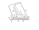
- the physiological saline supplied from the ejection port 18 and sucked from the suction port 19 perfuses the tip of the probe 7b.
- the physiological saline 42 exists in a certain range. That is, a physiological saline perfusion layer is formed on the distal end surface of the probe 7b and the outer peripheral surface near the distal end. As a result, the active electrode 15 and the return electrode 16 are immersed in physiological saline.
- a high frequency voltage is applied between the active electrode 15 and the return electrode 16 in a state where the active electrode 15 and the return electrode 16 are immersed in the physiological saline 42.
- the physiological saline 42 evaporates in the vicinity of the active electrode 15 and the return electrode 16, and a vapor layer is generated.
- a voltage is further applied between the active electrode 15 and the return electrode 16
- breakdown occurs in this vapor layer, and plasma is generated.
- the region where the plasma is generated is referred to as a plasma generation region P.
- the living tissue 41 in the vicinity of the plasma generation region P evaporates due to the generated plasma.
- the transpired biological tissue or the fragment of the destroyed biological tissue is sucked into the suction port 19 together with the physiological saline.
- the conditions for generating plasma include the shape of the active electrode 15 and the return electrode 16 and the structure such as the distance between the electrodes, the characteristics of the conductive solution used such as physiological saline, the amount of the conductive solution, It depends on temperature. For this reason, it is preferable that the positional relationship between the active electrode 15 and the return electrode 16 is fixed. Furthermore, the amount of physiological saline is an important factor for properly generating plasma.
- the surface area of the return electrode 16 is larger than the surface area of the active electrode 15 as the surface area of the electrode in contact with the physiological saline. Since the surface area of the active electrode 15 is small, the current density is increased in the vicinity of the active electrode 15, and desired plasma is generated in the vicinity of the active electrode 15. If the surface area of the return electrode 16 is larger than the surface area of the active electrode 15, the return electrode 16 plays a role of the active electrode 15, and the desired good plasma may not be generated.
- the active electrode 15 and the return electrode 16 function as a first electrode and a second electrode, and the active electrode 15 and the return electrode 16 are discharged from the jet port 18 and sucked from the suction port 19. It is provided so that a mutual positional relationship may be fixed at a position where it is immersed in the physiological saline.
- the supply suction unit 5 supplies and sucks physiological saline to the plasma treatment instrument 7 as described above. As shown in FIG. 1, the supply suction unit 5 is provided with a supply line 31 that supplies physiological saline to the plasma treatment instrument 7 and a suction line 32 that sucks physiological saline from the plasma treatment instrument 7. .
- a supply pump 33, a temperature adjustment unit 34, and a supply amount sensor 35 are provided from the upstream side, and the supply tube 39 on the downstream side is a first connection of the plasma treatment instrument 7. Connected to the tube 22.
- a suction tube 40, a suction amount sensor 38, a temperature sensor 37, and a suction pump 36 connected to the second connection tube 23 of the plasma treatment instrument 7 are provided from the upstream side.
- the downstream side of the suction pump 36 is connected to the drain tank 6.
- the supply pump 33 operates under the control of the control unit 2, takes out a new physiological saline from the physiological saline bag 4, and supplies it to the probe 7 b of the plasma treatment instrument 7.
- the supply pump 33 can change the amount of physiological saline supplied to the probe 7b under the control of the control unit 2.
- the supply pump 33 is not particularly limited, but preferably has a structure that is easy to manage and maintain in terms of hygiene, and a so-called roller pump that transports the liquid inside while crushing the elastic tube by the rotation of the roller. preferable.
- the temperature adjustment unit 34 cools or warms the physiological saline sent out from the supply pump 33 under the control of the control unit 2 and adjusts the temperature to a predetermined range suitable for treatment.
- the supply amount sensor 35 is a known flow rate sensor, and detects the supply amount of physiological saline supplied to the probe 7b.
- the supply amount sensor 35 transmits a signal indicating the detected supply amount to the control unit 2.
- the control unit 2 uses the supply amount detected by the supply amount sensor 35 to adjust the supply amount of the supply pump 33.
- the supply amount sensor 35 may not be provided, and the supply amount may be adjusted without using feedback control.
- the supply pump 33, the temperature adjustment unit 34, and the supply amount sensor 35 may be arranged in any order. Further, for example, the supply amount sensor 35 may be provided in the plasma treatment instrument 7 depending on its size and the like.
- the suction pump 36 operates under the control of the control unit 2 and sends the physiological saline sucked from the probe 7b to the drain tank 6.
- the suction pump 36 can change the amount of physiological saline sucked from the probe 7 b under the control of the control unit 2.
- the suction amount sensor 38 detects the amount of physiological saline sucked by the suction pump 36.
- the suction amount sensor 38 may be a known flow rate sensor, or a liquid level sensor or a water level sensor provided in the drain tank 6.
- the suction amount sensor 38 transmits a signal indicating the detected suction amount to the control unit 2.
- the temperature sensor 37 detects the temperature of the sucked physiological saline and transmits the detection result to the control unit 2.
- the control unit 2 uses the suction amount detected by the suction amount sensor 38 to adjust the suction amount of the suction pump 36.
- the suction amount sensor 38 is not provided, and the suction amount may be adjusted without feedback control.
- the suction pump 36, the temperature sensor 37, and the suction amount sensor 38 may be arranged in any order. Further, the temperature sensor 37 and the suction amount sensor 38 may be provided in the plasma treatment instrument 7 depending on the size thereof.
- the control unit 2 includes an impedance acquisition unit 201, a power control unit 202, and a liquid supply amount control unit 203.
- the impedance acquisition unit 201 is connected between the active electrode 15 and the return electrode 16 based on the voltage applied between the active electrode 15 and the return electrode 16 acquired from the power supply unit 3 and the current flowing therebetween. Calculate the impedance.
- the power control unit 202 controls the power supply to the plasma treatment instrument 7 by the power supply unit 3 based on the impedance calculated by the impedance acquisition unit 201.
- the liquid supply amount control unit 203 controls the operations of the supply pump 33 and the suction pump 36 based on the impedance calculated by the impedance acquisition unit 201.
- the liquid supply amount control unit 203 causes the supply pump 33 to change the supply amount or causes the suction pump 36 to change the suction amount.
- the power control unit 202 functions as a second control unit that controls the power supply unit that supplies power between the first electrode and the second electrode.
- the liquid supply amount control unit 203 functions as a first control unit that controls the liquid amount adjustment unit so as to increase or decrease the supply amount or suction amount of the conductive solution based on the impedance.
- the control unit 2 may be provided integrally with the power supply unit 3.
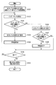
- the operation of the plasma treatment system 1 will be described with reference to the flowchart shown in FIG. Note that the processing shown in the flowchart shown in FIG. 4 is realized by arithmetic processing performed in the control unit 2 according to a program stored in a storage unit included in the control unit 2, for example.
- This program may be recorded in advance in the control unit 2, or may be recorded in various media.
- the control unit 2 may read the program from this medium, or may be provided online.
- the program may be acquired by communication.
- step S101 the control unit 2 sets the output level of the plasma treatment instrument 7 to a low output.
- the low output is not a high output in which plasma is generated by the plasma treatment instrument 7 in order to perform treatment, but a low output capable of measuring the impedance between the active electrode 15 and the return electrode 16.
- the control unit 2 controls the power supply unit 3 based on the set low output value, and causes the power supply unit 3 to supply power to the plasma treatment instrument 7 at a low output.
- the electric power may be controlled by a voltage value or a current value.
- the control unit 2 causes the supply pump 33 and the suction pump 36 to start driving these pumps.
- the supply amount of the supply pump 33 and the suction amount of the suction pump 36 are set to predetermined initial values, for example. This initial value may be set by the user, or may be set to a value recorded in advance in the control unit 2 or the plasma treatment instrument 7.
- step S102 the control unit 2 acquires the voltage and current supplied from the power supply unit 3 to the plasma treatment instrument 7, and calculates the impedance between the active electrode 15 and the return electrode 16.
- the impedance between the active electrode 15 and the return electrode 16 is used as the impedance.
- the impedance between the terminal 12a and the terminal 12b or the gap between the active electrode 15 and the return electrode 16 is used.
- Impedance of an arbitrary part in which the impedance between the active electrode 15 and the return electrode 16 is reflected, such as the impedance between two locations in the power supply unit 3 including, is related between the active electrode 15 and the return electrode 16. It may be used as an impedance.
- step S103 the control unit 2 determines whether or not the calculated impedance is higher than a predetermined first threshold value Z1.
- a predetermined first threshold value Z1 is set as an impedance measured when the tip of the probe 7b is not immersed in physiological saline.
- step S104 the control unit 2 sets the output of the plasma treatment instrument 7 to a low output, and causes the power supply unit 3 to supply power to the probe 7b at a low output.
- step S105 the control unit 2 controls the supply pump 33 so as to increase the supply amount of physiological saline. As a result, the amount of physiological saline present at the tip of the probe 7b gradually increases. After step S105, the process proceeds to step S109.
- step S103 When it is determined in step S103 that the impedance is not higher than the first threshold value Z1, the process proceeds to step S106. That the impedance is not higher than the first threshold value Z1 means that the tip of the probe 7b is immersed in physiological saline to the extent necessary for generating plasma.
- step S106 the control unit 2 sets the output level of the plasma treatment instrument 7 to a high output.
- the high output is an output that generates plasma at the tip of the probe 7b.
- the output level of high output may include a plurality of output levels depending on the type of plasma treatment instrument 7 and the method of treatment. However, here, they are referred to as high output without distinction.
- the control unit 2 controls the power supply unit 3 based on the set high output value, and causes the power supply unit 3 to supply power to the plasma treatment instrument 7 with high output. As a result, plasma is generated in a region where the tip of the physiological saline probe 7b is immersed.
- the treatment is performed by this plasma.
- the output at the high output level of the power supply unit 3 may be configured to be always output when the setting by the control unit 2 is high output, or when the setting by the control unit 2 is high output, and the input unit It may be configured to output when the 8 foot switch is stepped on. It should be noted that the impedance can be calculated based on the voltage value and the current value acquired by the power supply unit 3 even in a state where such a large power that generates plasma is supplied.
- step S107 the control unit 2 determines whether or not the impedance calculated in step S106 is lower than a predetermined second threshold Z2. For example, if the amount of physiological saline present at the tip of the probe 7b is larger than an appropriate amount, plasma is not efficiently generated at the tip. At this time, the measured impedance is lower than when plasma is generated.
- the impedance measured when the active electrode 15 and the return electrode 16 are immersed in pure physiological saline not mixed with impurities is defined as a first impedance. Further, the impedance measured when plasma is generated is defined as a second impedance. The second impedance is higher than the first impedance.
- the physiological saline in which the active electrode 15 and the return electrode 16 are immersed in the tissue Impurities such as origin are mixed.
- the impedance measured at this time is defined as a third impedance.
- the third impedance is higher than the first impedance and lower than the second impedance.
- the second threshold value Z2 can be set to a value higher than the third impedance and lower than the second impedance.
- step S107 When it is determined in step S107 that the impedance is not lower than the second threshold value Z2, the process proceeds to step S109.
- step S108 the control unit 2 controls the supply pump 33 so as to reduce the supply amount of physiological saline. As a result, the amount of physiological saline present at the tip of the probe 7b gradually decreases. After step S108, the process proceeds to step S109.
- step S109 the control unit 2 determines whether or not an instruction to end the treatment is input by the user. When the end instruction is not input, the process returns to step S102 and the above process is repeated. On the other hand, when an end instruction is input, the process proceeds to step S110.
- step S110 the control unit 2 causes the power supply unit 3 to stop supplying power to the probe 7b. Further, the control unit 2 causes the supply pump 33 to stop the supply of physiological saline, and subsequently causes the suction pump 36 to stop the suction. Thereafter, the process ends.
- the amount of physiological saline present at the tip of the probe 7b when the amount of physiological saline present at the tip of the probe 7b is small to generate plasma, the amount of physiological saline supplied by the supply pump 33 is increased. When the amount of physiological saline present at the tip of the probe 7b is too large to generate plasma, the amount of physiological saline supplied by the supply pump 33 is reduced. As a result, an amount of physiological saline suitable for plasma generation is always maintained at the tip of the probe 7b.
- the plasma treatment system 1 according to the present embodiment can reduce the risk of such complications.
- the plasma treatment system 1 according to the present embodiment is effective in the field of performing plasma treatment by perfusing physiological saline only at the distal end portion of the probe 7b as in the treatment in the otolaryngology region.
- the impedance when the output level is high and large electric power is supplied to the probe 7b, the impedance is calculated based on the voltage value and current value at that time.
- the output level when the power supply unit 3 outputs a large amount of power to generate plasma, the output level is set to a low output for a short time of, for example, several milliseconds in order to acquire impedance, and the voltage value acquired at this time
- the impedance may be calculated based on the current value.
- the impedance calculation system is improved by always performing the calculation of the impedance in a low output state.
- the present invention is not limited to this.
- the amount of physiological saline sucked by the suction pump 36 may be controlled. That is, for example, in step S105, instead of increasing the supply amount of the physiological saline, the suction amount of the physiological saline may be decreased. Similarly, in step S108, instead of decreasing the supply amount of physiological saline, the suction amount of physiological saline may be increased. Moreover, both the supply amount of physiological saline and the suction amount may be controlled.
- the plasma treatment system 1 may be configured to adjust the output of the power supply unit 3 based on the impedance in order to perform an appropriate treatment.
- the power control unit 202 may determine the amount of the substance derived from the biological tissue contained in the physiological saline that is the conductive solution based on the impedance, and may control the output of the power supply unit 3. .
- the start and end of the treatment are described as being input by the user, but are not limited thereto.
- a sensor is provided at the tip of the probe 7b, and the process starts when the tip of the probe 7b is pressed against the treatment target site by the sensor, and the process ends when a predetermined time elapses. Also good.
- the plasma treatment device 7 of the present embodiment is provided with a jet port 18 and a suction port 19, and the supply and suction of physiological saline are performed by the probe 7b, but the configuration is not limited thereto.
- the active electrode 15 and the return electrode 16 are provided in the probe 7b, and the supply and suction of the physiological saline may be performed by a supply probe and a suction probe different from the probe 7b.
- the plasma treatment instrument 7 with the jet port 18 and the suction port 19 as in the above embodiment, access to the treatment target is facilitated and treatment is easily performed. For this reason, it is preferable that the plasma treatment tool 7 is provided with a jet port 18 and a suction port 19.
- the supply pump 33 is used to supply physiological saline and adjust the supply amount, but is not limited thereto.
- the physiological saline bag 4 may be disposed at a high position, and the physiological saline may be supplied to the probe 7b by gravity. At this time, a valve may be provided in the supply line to adjust the supply amount.
- the suction pump 36 is used for the suction of physiological saline and the adjustment of the suction amount, but the present invention is not limited to this.
- the physiological saline may be sucked from the probe 7b by a wall suction device provided in the treatment room.
- a valve may be provided in the suction line to adjust the suction amount.
- the plasma treatment system 1 includes a liquid amount adjusting unit that adjusts the supply amount or suction amount of, for example, physiological saline that is a conductive solution
- the liquid amount adjusting unit may have any configuration. .
- the processing shown in FIG. 4 is an example, and for example, the order of the processing may be changed as appropriate, and a part of the processing may be deleted.
- the liquid supply amount is adjusted according to the impedance, but the output level may not be changed, or only the output level may be changed.
- the plasma treatment system 1 has been described so as to be able to perform only the treatment of evaporating the biological tissue that is the treatment target, the present invention is not limited to this.
- the plasma treatment system 1 can be configured so that the living tissue to be treated can be coagulated.
- the output can be set lower than when transpiring.
- the plasma treatment system 1 can be configured such that the transpiration mode and the coagulation mode can be switched as appropriate. These switching operations may be performed by the user, or may be set in advance according to the procedure of the treatment.
- control unit 2 determines various situations of the distal end portion of the probe 7 b of the plasma treatment instrument 7 based on the impedance between the active electrode 15 and the return electrode 16.
- FIG. 5 shows an outline of an example of the relationship between the state of the tip of the probe 7b and the impedance between the active electrode 15 and the return electrode 16 measured at that time.
- the impedance is lowest when there is pure physiological saline between the active electrode 15 and the return electrode 16.
- the impedance becomes higher than that of pure physiological saline.
- the active electrode 15 and the return electrode 16 are in contact with the living tissue, the impedance is higher than when the electrode is immersed in physiological saline.
- the impedance becomes higher than in the state where the active electrode 15 and the return electrode 16 are in contact with the living tissue. Further, in the state where there is no physiological saline between the active electrode 15 and the return electrode 16 and no plasma is generated, the impedance is higher than in the state where plasma is generated.
- the plasma treatment system 1 determines these states based on the impedance, and performs an operation suitable for the state.
- step S ⁇ b> 201 the control unit 2 sets the output level to a low output and starts driving the supply pump 33 and the suction pump 36.
- step S ⁇ b> 202 the control unit 2 calculates the impedance between the active electrode 15 and the return electrode 16.
- step S203 the control unit 2 determines whether a high output level has been output in the series of operations thus far. This is because there is a possibility that a substance derived from a living tissue is mixed in physiological saline by plasma treatment when the output of a high output level has already been performed. This is for changing the threshold value used in the subsequent processing. If it is determined that a high output level has been output, the process proceeds to step S206. On the other hand, when it is determined that the high output level is not output, the process proceeds to step S204.
- step S204 the control unit 2 determines whether or not the calculated impedance is higher than the third threshold value Z3.
- the third threshold value is higher than the impedance when the probe 7b is immersed in pure physiological saline, and is immersed in physiological saline mixed with a substance derived from living tissue. It is a value lower than the impedance when When it is determined that the impedance is higher than the third threshold value Z3, the process proceeds to step S205. At this time, it is considered that the tip of the probe 7b is not immersed in physiological saline. Therefore, in step S205, the control unit 2 increases the supply amount of physiological saline. Thereafter, the process proceeds to step S209. On the other hand, when it is determined in step S204 that the impedance is not higher than the third threshold value Z3, the process proceeds to step S207.
- step S206 the control unit 2 determines whether or not the calculated impedance is higher than the fourth threshold value Z4.
- the fourth threshold is higher than the impedance when the probe 7b is immersed in a physiological saline mixed with a substance derived from a living tissue, and the probe 7b and the living tissue are in contact with each other. It is a value lower than the impedance when When it is determined that the impedance is not higher than the fourth threshold value Z4, the process proceeds to step S207. At this time, it is considered that the tip of the probe 7b is immersed in physiological saline.
- the control unit 2 performs high output level control described later. Thereafter, the process proceeds to step S209.
- step S206 If it is determined in step S206 that the impedance is higher than the fourth threshold value Z4, the process proceeds to step S208. At this time, it is considered that the tip of the probe 7b is not immersed in physiological saline. In step S205, the control unit 2 increases the supply amount of physiological saline. Thereafter, the process proceeds to step S209.
- step S209 the control unit 2 determines whether an instruction to end the treatment is input by the user. If no termination instruction has been input, the process returns to step S202, and the above process is repeated. On the other hand, when an end instruction is input, the process proceeds to step S210.
- step S210 the control unit 2 causes the power supply unit 3 to stop supplying power to the probe 7b. Further, the control unit 2 causes the supply pump 33 to stop the supply of physiological saline, and subsequently causes the suction pump 36 to stop the suction. Thereafter, the process ends.
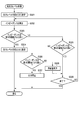
- High output level control is control performed when the output level is set to a high output level.
- the control unit 2 sets the output level to high output. Thereafter, the process proceeds to step S302.
- the control unit 2 calculates the impedance between the active electrode 15 and the return electrode 16.
- step S303 the control unit 2 determines whether the impedance is higher than the fifth threshold value Z5.
- the fifth threshold value Z5 is a value that is slightly lower than the impedance measured in the absence of physiological saline at the tip of the probe 7b. That is, when the impedance is higher than the fifth threshold value Z5, it is considered that there is no physiological saline at the tip of the probe 7b.
- the control unit 2 sets the output level to low output. Thereafter, the process returns to step S207.
- step S305 the control unit 2 determines whether the impedance is higher than the sixth threshold value Z6.
- the sixth threshold value Z6 is a value slightly lower than the impedance measured in a state where plasma is generated at the tip of the probe 7b. That is, it is considered that when the impedance is higher than the sixth threshold value Z6, plasma is generated at the tip of the probe 7b.
- the process proceeds to step S309.
- step S305 When it is determined in step S305 that the impedance is not higher than the sixth threshold value Z6, the process proceeds to step S306.
- step S306 the control unit 2 determines whether or not the impedance is higher than the seventh threshold value Z7.
- the seventh threshold value Z7 is a value slightly lower than the impedance measured in a state where the distal end portion of the probe 7b is in contact with the biological tissue to be treated. That is, when the impedance is higher than the seventh threshold value Z7, it is considered that the tip of the probe 7b is in contact with the living tissue.
- the process proceeds to step S307.
- step S307 the control unit 2 stops the power supply between the active electrode 15 and the return electrode 16. Thereafter, the process returns to step S207.
- step S306 When it is determined in step S306 that the impedance is not higher than the seventh threshold value Z7, the process proceeds to step S308. At this time, the physiological saline at the tip of the probe 7b is excessive, and it is considered that plasma is not generated efficiently. Therefore, in step S308, the control unit 2 decreases the supply amount of physiological saline. Thereafter, the process proceeds to step S309.
- step S309 the control unit 2 determines whether an instruction to end the treatment is input by the user. When the end instruction has not been input, the process returns to step S302 to repeat the above process. On the other hand, when an end instruction is input, the process returns to step S207.
- the plasma treatment system 1 can determine the state of the distal end portion of the probe 7b based on the impedance and perform an operation suitable for the state.
- the case where the power supply to the active electrode 15 and the return electrode 16 is stopped when the tip of the probe 7b and the living tissue to be treated are in contact has been described as an example.
- the present invention is not limited thereto.
- the supplied power may be set to a low output level so that the impedance can be measured.
- the power supply may be adjusted according to the amount and composition of the biological tissue contained in the physiological saline, or the amount of physiological saline supplied may be changed.
- a jet port configured to discharge a conductive solution
- a suction port configured to suck the conductive solution
- a first electrode and a second electrode provided so that the mutual positional relationship is fixed at a position soaked in the solution, and a voltage is provided between the first electrode and the second electrode.
- a plasma treatment control unit used together with a plasma treatment tool for treating living tissue with plasma generated by being applied, and a liquid amount adjusting unit for adjusting the supply amount or suction amount of the conductive solution,
- An impedance acquisition unit for acquiring an impedance between the first electrode and the second electrode;
- a plasma treatment control unit comprising: a liquid supply amount control unit configured to increase or decrease the supply amount or suction amount of the conductive solution in the liquid amount adjustment unit based on the impedance.
Abstract
Description
本発明の第1の実施形態について図面を参照して説明する。図1は、本実施形態に係るプラズマ処置システム1の全体の構成の概略を示すブロック図である。このプラズマ処置システム1は、プラズマを発生させ、このプラズマによって処置対象である生体組織を蒸散させる処置に用いられる。プラズマを利用した生体組織の切除により、切除組織周辺への熱損傷は比較的小さくなり、低侵襲な処置が実現される。プラズマ処置システム1は、例えば耳鼻咽喉科分野において、扁桃組織の切除術などに用いられる。また、このプラズマ処置システム1は、例えば、整形外科分野において滑膜の切除、軟骨の切除などに用いても良いし、開腹手術全般において臓器(特に肝臓)の切除などに用いても良い。
本発明の第2の実施形態について説明する。ここでは、第1の実施形態との相違点について説明し、同一の部分については、同一の符号を付してその説明を省略する。本実施形態に係る制御部2は、アクティブ電極15とリターン電極16との間のインピーダンスに基づいて、プラズマ処置具7のプローブ7bの先端部の種々の状況を判断する。
[1] 導電性溶液を吐出するように構成された噴出口と、前記導電性溶液を吸引するように構成された吸引口と、前記噴出口から吐出され前記吸引口から吸引される前記導電性溶液に浸るような位置に互いの位置関係が固定されるように設けられた第1の電極及び第2の電極とを備え、前記第1の電極と前記第2の電極との間に電圧が印加されることで発生するプラズマによって生体組織を処置するためのプラズマ処置具と、前記導電性溶液の供給量又は吸引量を調整する液量調整部とともに用いられるプラズマ処置制御ユニットであって、
前記第1の電極と前記第2の電極との間に係るインピーダンスを取得するインピーダンス取得部と、
前記インピーダンスに基づいて、前記液量調整部に前記導電性溶液の供給量又は吸引量を増減させる送液量制御部と
を具備するプラズマ処置制御ユニット。
Claims (8)
- 導電性溶液を吐出するように構成された噴出口と、
前記導電性溶液を吸引するように構成された吸引口と、
前記噴出口から吐出され前記吸引口から吸引される前記導電性溶液に浸るような位置に互いの位置関係が固定されるように設けられ、電圧が印加されることで生体組織を処置するためのプラズマを発生するように構成された第1の電極及び第2の電極と、
前記第1の電極と前記第2の電極との間に係るインピーダンスを取得するインピーダンス取得部と、
前記導電性溶液の供給量又は吸引量を調整する液量調整部と、
前記インピーダンスに基づいて、前記導電性溶液の供給量又は吸引量を増減させるように前記液量調整部を制御する第1の制御部と
を具備するプラズマ処置システム。 - 前記第1の制御部は、前記インピーダンスと所定の閾値とを比較して前記第1の電極と前記第2の電極との間に前記導電性溶液が満たされているか否かを判定する、請求項1に記載のプラズマ処置システム。
- 前記第1の制御部は、前記第1の電極と前記第2の電極との間に前記導電性溶液が満たされていないと判定したとき、前記導電性溶液の供給量を増加させること、及び前記導電性溶液の吸引量を減少させることのうち少なくとも何れか一方を前記液量調整部に行わせる、請求項2に記載のプラズマ処置システム。
- 前記第1の制御部は、前記インピーダンスと所定の閾値とを比較して前記第1の電極と前記第2の電極との間にプラズマが発生しているか否かを判定する、請求項1に記載のプラズマ処置システム。
- 前記第1の制御部は、プラズマが発生していないと判定したとき、前記導電性溶液の供給量を減少させること、及び前記導電性溶液の吸引量を増加させることのうち少なくとも何れか一方を前記液量調整部に行わせる、請求項4に記載のプラズマ処置システム。
- 前記第1の電極と前記第2の電極との間に電力を供給する電源部を制御する第2の制御部をさらに具備し、
前記第2の制御部は、
前記第1の電極と前記第2の電極との間に前記導電性溶液が満たされていると判定されたとき、前記第1の電極と前記第2の電極との間に、前記プラズマが発生するような第1の電力を前記電源部に供給させ、
前記第1の電極と前記第2の電極との間に前記導電性溶液が満たされていないと判定されたとき、前記第1の電極と前記第2の電極との間に、第1の電力よりも低い、前記第1の電極と前記第2の電極との間に前記プラズマが発生しないような第2の電力を前記電源部に供給させる、
請求項2に記載のプラズマ処置システム。 - 前記第1の電極と前記第2の電極との間に電力を供給する電源部を制御する第2の制御部をさらに具備し、
前記第2の制御部は、
前記プラズマを発生させるときは前記プラズマが発生するような第1の電力を前記電源部に供給させ、
前記インピーダンスを取得するときは、前記第1の電極と前記第2の電極との間に、第1の電力よりも低い、前記第1の電極と前記第2の電極との間に前記プラズマが発生しないような第2の電力を前記電源部に供給させる、
請求項1に記載のプラズマ処置システム。 - 前記第1の電極と前記第2の電極との間に電力を供給する電源部を制御する第2の制御部をさらに具備し、
前記第2の制御部は、前記インピーダンスに基づいて、前記電源部の出力を制御する、
請求項1に記載のプラズマ処置システム。
Priority Applications (4)
| Application Number | Priority Date | Filing Date | Title |
|---|---|---|---|
| EP15776202.2A EP3130302A4 (en) | 2014-04-11 | 2015-03-27 | Plasma treatment system |
| CN201580002805.2A CN105792764B (zh) | 2014-04-11 | 2015-03-27 | 等离子体处置系统 |
| JP2015544260A JP5897230B1 (ja) | 2014-04-11 | 2015-03-27 | プラズマ処置システム |
| US15/187,477 US9827032B2 (en) | 2014-04-11 | 2016-06-20 | Plasma treatment system |
Applications Claiming Priority (2)
| Application Number | Priority Date | Filing Date | Title |
|---|---|---|---|
| JP2014-082287 | 2014-04-11 | ||
| JP2014082287 | 2014-04-11 |
Related Child Applications (1)
| Application Number | Title | Priority Date | Filing Date |
|---|---|---|---|
| US15/187,477 Continuation US9827032B2 (en) | 2014-04-11 | 2016-06-20 | Plasma treatment system |
Publications (1)
| Publication Number | Publication Date |
|---|---|
| WO2015156157A1 true WO2015156157A1 (ja) | 2015-10-15 |
Family
ID=54287734
Family Applications (1)
| Application Number | Title | Priority Date | Filing Date |
|---|---|---|---|
| PCT/JP2015/059756 WO2015156157A1 (ja) | 2014-04-11 | 2015-03-27 | プラズマ処置システム |
Country Status (5)
| Country | Link |
|---|---|
| US (1) | US9827032B2 (ja) |
| EP (1) | EP3130302A4 (ja) |
| JP (1) | JP5897230B1 (ja) |
| CN (1) | CN105792764B (ja) |
| WO (1) | WO2015156157A1 (ja) |
Cited By (5)
| Publication number | Priority date | Publication date | Assignee | Title |
|---|---|---|---|---|
| JP2021037252A (ja) * | 2019-08-30 | 2021-03-11 | 珠海市司邁科技有限公司Simai Co., Ltd. | 耳鼻咽喉科用プラズマ手術電極 |
| JP2021516138A (ja) * | 2017-10-27 | 2021-07-01 | 上海諾英医療器械有限公司Neowing Medical Co., Ltd. | 低温プラズマ型切開メスデバイス、システム及び方法 |
| JP2021516139A (ja) * | 2017-10-27 | 2021-07-01 | 上海諾英医療器械有限公司Neowing Medical Co., Ltd. | 低温プラズマ型剥離メスデバイス、システム及び方法 |
| JP2021516137A (ja) * | 2017-10-27 | 2021-07-01 | 上海諾英医療器械有限公司Neowing Medical Co., Ltd. | 低温プラズマ型スネアデバイス、システム及び方法 |
| JP2021154128A (ja) * | 2020-03-27 | 2021-10-07 | オリンパス・ウィンター・アンド・イベ・ゲゼルシャフト・ミット・ベシュレンクテル・ハフツング | 電気外科手術用ジェネレータ、電気外科手術用システムおよび電気外科手術用ジェネレータを動作させるための方法 |
Families Citing this family (10)
| Publication number | Priority date | Publication date | Assignee | Title |
|---|---|---|---|---|
| US20200121379A1 (en) * | 2017-04-19 | 2020-04-23 | Ngk Spark Plug Co., Ltd. | Plasma irradiation device, handpiece, and surgical operation device |
| CN107693111A (zh) * | 2017-10-27 | 2018-02-16 | 上海诺英医疗器械有限公司 | 一种低温等离子切开刀手术设备 |
| CN107736934A (zh) * | 2017-10-27 | 2018-02-27 | 上海诺英医疗器械有限公司 | 一种低温等离子剥离刀手术设备 |
| CN107736931A (zh) * | 2017-10-27 | 2018-02-27 | 上海诺英医疗器械有限公司 | 一种低温等离子圈套刀手术设备 |
| CN107693113A (zh) * | 2017-10-27 | 2018-02-16 | 上海诺英医疗器械有限公司 | 一种低温等离子圈套刀手术系统及方法 |
| CN107736935A (zh) * | 2017-10-27 | 2018-02-27 | 上海诺英医疗器械有限公司 | 一种低温等离子切开刀手术系统及方法 |
| CN107736932A (zh) * | 2017-10-27 | 2018-02-27 | 上海诺英医疗器械有限公司 | 一种低温等离子剥离刀手术系统及方法 |
| EP3569171B1 (de) * | 2018-05-14 | 2024-03-13 | Erbe Elektromedizin GmbH | Vorrichtung und verfahren zum vorgeben von betriebsparametern zur erzeugung eines plasmas in wässriger umgebung |
| CN109374875A (zh) * | 2018-11-20 | 2019-02-22 | 中国科学院生物物理研究所 | 低噪恒温重力灌流膜片钳装置 |
| CN112603526A (zh) * | 2020-12-17 | 2021-04-06 | 北京凯卓迅达科技有限公司 | 射频等离子手术系统及其使用方法 |
Citations (2)
| Publication number | Priority date | Publication date | Assignee | Title |
|---|---|---|---|---|
| JP2003305054A (ja) * | 2002-04-15 | 2003-10-28 | Olympus Optical Co Ltd | 電気手術装置 |
| US20080167645A1 (en) * | 2007-01-05 | 2008-07-10 | Jean Woloszko | Electrosurgical system with suction control apparatus, system and method |
Family Cites Families (13)
| Publication number | Priority date | Publication date | Assignee | Title |
|---|---|---|---|---|
| US6409722B1 (en) * | 1998-07-07 | 2002-06-25 | Medtronic, Inc. | Apparatus and method for creating, maintaining, and controlling a virtual electrode used for the ablation of tissue |
| US5733281A (en) * | 1996-03-19 | 1998-03-31 | American Ablation Co., Inc. | Ultrasound and impedance feedback system for use with electrosurgical instruments |
| US7357798B2 (en) * | 1996-07-16 | 2008-04-15 | Arthrocare Corporation | Systems and methods for electrosurgical prevention of disc herniations |
| CA2232967C (en) * | 1997-04-11 | 2008-10-21 | United States Surgical Corporation | Controller for thermal treatment of tissue |
| WO1998056324A1 (en) * | 1997-06-13 | 1998-12-17 | Arthrocare Corporation | Electrosurgical systems and methods for recanalization of occluded body lumens |
| JP2002508214A (ja) | 1997-12-15 | 2002-03-19 | アースロケア コーポレイション | 頭部および頸部の電気外科治療用のシステムおよび方法 |
| US7435247B2 (en) * | 1998-08-11 | 2008-10-14 | Arthrocare Corporation | Systems and methods for electrosurgical tissue treatment |
| US8083736B2 (en) * | 2000-03-06 | 2011-12-27 | Salient Surgical Technologies, Inc. | Fluid-assisted medical devices, systems and methods |
| EP1429678B1 (en) * | 2001-09-28 | 2006-03-22 | Rita Medical Systems, Inc. | Impedance controlled tissue ablation apparatus |
| US6929643B2 (en) | 2002-04-15 | 2005-08-16 | Olympus Corporation | Resectoscope apparatus and electric operation apparatus |
| WO2005110263A2 (en) * | 2004-05-11 | 2005-11-24 | Wisconsin Alumni Research Foundation | Radiofrequency ablation with independently controllable ground pad conductors |
| JP4882824B2 (ja) * | 2007-03-27 | 2012-02-22 | 東京エレクトロン株式会社 | プラズマ処理装置、プラズマ処理方法及び記憶媒体 |
| JP5979350B2 (ja) * | 2012-03-30 | 2016-08-24 | 国立大学法人名古屋大学 | プラズマ発生装置 |
-
2015
- 2015-03-27 CN CN201580002805.2A patent/CN105792764B/zh active Active
- 2015-03-27 JP JP2015544260A patent/JP5897230B1/ja not_active Expired - Fee Related
- 2015-03-27 WO PCT/JP2015/059756 patent/WO2015156157A1/ja active Application Filing
- 2015-03-27 EP EP15776202.2A patent/EP3130302A4/en not_active Withdrawn
-
2016
- 2016-06-20 US US15/187,477 patent/US9827032B2/en active Active
Patent Citations (2)
| Publication number | Priority date | Publication date | Assignee | Title |
|---|---|---|---|---|
| JP2003305054A (ja) * | 2002-04-15 | 2003-10-28 | Olympus Optical Co Ltd | 電気手術装置 |
| US20080167645A1 (en) * | 2007-01-05 | 2008-07-10 | Jean Woloszko | Electrosurgical system with suction control apparatus, system and method |
Non-Patent Citations (1)
| Title |
|---|
| See also references of EP3130302A4 * |
Cited By (8)
| Publication number | Priority date | Publication date | Assignee | Title |
|---|---|---|---|---|
| JP2021516138A (ja) * | 2017-10-27 | 2021-07-01 | 上海諾英医療器械有限公司Neowing Medical Co., Ltd. | 低温プラズマ型切開メスデバイス、システム及び方法 |
| JP2021516139A (ja) * | 2017-10-27 | 2021-07-01 | 上海諾英医療器械有限公司Neowing Medical Co., Ltd. | 低温プラズマ型剥離メスデバイス、システム及び方法 |
| JP2021516137A (ja) * | 2017-10-27 | 2021-07-01 | 上海諾英医療器械有限公司Neowing Medical Co., Ltd. | 低温プラズマ型スネアデバイス、システム及び方法 |
| JP2021037252A (ja) * | 2019-08-30 | 2021-03-11 | 珠海市司邁科技有限公司Simai Co., Ltd. | 耳鼻咽喉科用プラズマ手術電極 |
| US11484356B2 (en) | 2019-08-30 | 2022-11-01 | Simai Co., Ltd. | Plasma operation electrode for otolaryngology department |
| JP2021154128A (ja) * | 2020-03-27 | 2021-10-07 | オリンパス・ウィンター・アンド・イベ・ゲゼルシャフト・ミット・ベシュレンクテル・ハフツング | 電気外科手術用ジェネレータ、電気外科手術用システムおよび電気外科手術用ジェネレータを動作させるための方法 |
| JP7293276B2 (ja) | 2020-03-27 | 2023-06-19 | オリンパス・ウィンター・アンド・イベ・ゲゼルシャフト・ミット・ベシュレンクテル・ハフツング | 電気外科手術用ジェネレータ、電気外科手術用システムおよび電気外科手術用ジェネレータを動作させるための方法 |
| US11918270B2 (en) | 2020-03-27 | 2024-03-05 | Olympus Winter & Ibe Gmbh | Electrosurgical generator, electrosurgical system, and method of operating an electrosurgical generator |
Also Published As
| Publication number | Publication date |
|---|---|
| EP3130302A1 (en) | 2017-02-15 |
| US20160302843A1 (en) | 2016-10-20 |
| JPWO2015156157A1 (ja) | 2017-04-13 |
| US9827032B2 (en) | 2017-11-28 |
| EP3130302A4 (en) | 2017-12-13 |
| CN105792764A (zh) | 2016-07-20 |
| JP5897230B1 (ja) | 2016-03-30 |
| CN105792764B (zh) | 2018-11-02 |
Similar Documents
| Publication | Publication Date | Title |
|---|---|---|
| JP5897230B1 (ja) | プラズマ処置システム | |
| US20220287759A1 (en) | Electrosurgical methods and systems | |
| US20200261139A1 (en) | System and methods of controlling temperature related to electrosurgical procedures | |
| US20200008859A1 (en) | Electrosurgical system with device specific operational parameters | |
| US9095358B2 (en) | Electrosurgery irrigation primer systems and methods | |
| EP3624715B1 (en) | Electrosurgical systems | |
| WO2015156158A1 (ja) | プラズマ処置システム | |
| US20200179031A1 (en) | Method and system related to electrosurgical procedures | |
| JP5953445B2 (ja) | プラズマ処置システム | |
| JP6660638B2 (ja) | Rf電極を有する空洞形成超音波外科用吸引装置 | |
| US20220071685A1 (en) | Multi-channel rf impedance |
Legal Events
| Date | Code | Title | Description |
|---|---|---|---|
| ENP | Entry into the national phase |
Ref document number: 2015544260 Country of ref document: JP Kind code of ref document: A |
|
| 121 | Ep: the epo has been informed by wipo that ep was designated in this application |
Ref document number: 15776202 Country of ref document: EP Kind code of ref document: A1 |
|
| NENP | Non-entry into the national phase |
Ref country code: DE |
|
| REEP | Request for entry into the european phase |
Ref document number: 2015776202 Country of ref document: EP |
|
| WWE | Wipo information: entry into national phase |
Ref document number: 2015776202 Country of ref document: EP |