WO2015156155A1 - Nonaqueous electrolyte secondary battery - Google Patents
Nonaqueous electrolyte secondary battery Download PDFInfo
- Publication number
- WO2015156155A1 WO2015156155A1 PCT/JP2015/059729 JP2015059729W WO2015156155A1 WO 2015156155 A1 WO2015156155 A1 WO 2015156155A1 JP 2015059729 W JP2015059729 W JP 2015059729W WO 2015156155 A1 WO2015156155 A1 WO 2015156155A1
- Authority
- WO
- WIPO (PCT)
- Prior art keywords
- battery
- positive electrode
- capacity
- active material
- electrolyte secondary
- Prior art date
Links
Images


Classifications
-
- H—ELECTRICITY
- H01—ELECTRIC ELEMENTS
- H01M—PROCESSES OR MEANS, e.g. BATTERIES, FOR THE DIRECT CONVERSION OF CHEMICAL ENERGY INTO ELECTRICAL ENERGY
- H01M10/00—Secondary cells; Manufacture thereof
- H01M10/05—Accumulators with non-aqueous electrolyte
- H01M10/052—Li-accumulators
- H01M10/0525—Rocking-chair batteries, i.e. batteries with lithium insertion or intercalation in both electrodes; Lithium-ion batteries
-
- H—ELECTRICITY
- H01—ELECTRIC ELEMENTS
- H01M—PROCESSES OR MEANS, e.g. BATTERIES, FOR THE DIRECT CONVERSION OF CHEMICAL ENERGY INTO ELECTRICAL ENERGY
- H01M10/00—Secondary cells; Manufacture thereof
- H01M10/04—Construction or manufacture in general
- H01M10/0413—Large-sized flat cells or batteries for motive or stationary systems with plate-like electrodes
-
- H—ELECTRICITY
- H01—ELECTRIC ELEMENTS
- H01M—PROCESSES OR MEANS, e.g. BATTERIES, FOR THE DIRECT CONVERSION OF CHEMICAL ENERGY INTO ELECTRICAL ENERGY
- H01M10/00—Secondary cells; Manufacture thereof
- H01M10/60—Heating or cooling; Temperature control
- H01M10/62—Heating or cooling; Temperature control specially adapted for specific applications
- H01M10/625—Vehicles
-
- H—ELECTRICITY
- H01—ELECTRIC ELEMENTS
- H01M—PROCESSES OR MEANS, e.g. BATTERIES, FOR THE DIRECT CONVERSION OF CHEMICAL ENERGY INTO ELECTRICAL ENERGY
- H01M10/00—Secondary cells; Manufacture thereof
- H01M10/60—Heating or cooling; Temperature control
- H01M10/64—Heating or cooling; Temperature control characterised by the shape of the cells
- H01M10/647—Prismatic or flat cells, e.g. pouch cells
-
- H—ELECTRICITY
- H01—ELECTRIC ELEMENTS
- H01M—PROCESSES OR MEANS, e.g. BATTERIES, FOR THE DIRECT CONVERSION OF CHEMICAL ENERGY INTO ELECTRICAL ENERGY
- H01M10/00—Secondary cells; Manufacture thereof
- H01M10/60—Heating or cooling; Temperature control
- H01M10/65—Means for temperature control structurally associated with the cells
- H01M10/651—Means for temperature control structurally associated with the cells characterised by parameters specified by a numeric value or mathematical formula, e.g. ratios, sizes or concentrations
-
- H—ELECTRICITY
- H01—ELECTRIC ELEMENTS
- H01M—PROCESSES OR MEANS, e.g. BATTERIES, FOR THE DIRECT CONVERSION OF CHEMICAL ENERGY INTO ELECTRICAL ENERGY
- H01M4/00—Electrodes
- H01M4/02—Electrodes composed of, or comprising, active material
- H01M4/13—Electrodes for accumulators with non-aqueous electrolyte, e.g. for lithium-accumulators; Processes of manufacture thereof
- H01M4/131—Electrodes based on mixed oxides or hydroxides, or on mixtures of oxides or hydroxides, e.g. LiCoOx
-
- H—ELECTRICITY
- H01—ELECTRIC ELEMENTS
- H01M—PROCESSES OR MEANS, e.g. BATTERIES, FOR THE DIRECT CONVERSION OF CHEMICAL ENERGY INTO ELECTRICAL ENERGY
- H01M4/00—Electrodes
- H01M4/02—Electrodes composed of, or comprising, active material
- H01M4/36—Selection of substances as active materials, active masses, active liquids
- H01M4/48—Selection of substances as active materials, active masses, active liquids of inorganic oxides or hydroxides
- H01M4/50—Selection of substances as active materials, active masses, active liquids of inorganic oxides or hydroxides of manganese
- H01M4/505—Selection of substances as active materials, active masses, active liquids of inorganic oxides or hydroxides of manganese of mixed oxides or hydroxides containing manganese for inserting or intercalating light metals, e.g. LiMn2O4 or LiMn2OxFy
-
- H—ELECTRICITY
- H01—ELECTRIC ELEMENTS
- H01M—PROCESSES OR MEANS, e.g. BATTERIES, FOR THE DIRECT CONVERSION OF CHEMICAL ENERGY INTO ELECTRICAL ENERGY
- H01M4/00—Electrodes
- H01M4/02—Electrodes composed of, or comprising, active material
- H01M4/36—Selection of substances as active materials, active masses, active liquids
- H01M4/48—Selection of substances as active materials, active masses, active liquids of inorganic oxides or hydroxides
- H01M4/52—Selection of substances as active materials, active masses, active liquids of inorganic oxides or hydroxides of nickel, cobalt or iron
- H01M4/525—Selection of substances as active materials, active masses, active liquids of inorganic oxides or hydroxides of nickel, cobalt or iron of mixed oxides or hydroxides containing iron, cobalt or nickel for inserting or intercalating light metals, e.g. LiNiO2, LiCoO2 or LiCoOxFy
-
- H—ELECTRICITY
- H01—ELECTRIC ELEMENTS
- H01M—PROCESSES OR MEANS, e.g. BATTERIES, FOR THE DIRECT CONVERSION OF CHEMICAL ENERGY INTO ELECTRICAL ENERGY
- H01M10/00—Secondary cells; Manufacture thereof
- H01M10/05—Accumulators with non-aqueous electrolyte
- H01M10/058—Construction or manufacture
- H01M10/0585—Construction or manufacture of accumulators having only flat construction elements, i.e. flat positive electrodes, flat negative electrodes and flat separators
-
- H—ELECTRICITY
- H01—ELECTRIC ELEMENTS
- H01M—PROCESSES OR MEANS, e.g. BATTERIES, FOR THE DIRECT CONVERSION OF CHEMICAL ENERGY INTO ELECTRICAL ENERGY
- H01M4/00—Electrodes
- H01M4/02—Electrodes composed of, or comprising, active material
- H01M2004/026—Electrodes composed of, or comprising, active material characterised by the polarity
- H01M2004/028—Positive electrodes
-
- H—ELECTRICITY
- H01—ELECTRIC ELEMENTS
- H01M—PROCESSES OR MEANS, e.g. BATTERIES, FOR THE DIRECT CONVERSION OF CHEMICAL ENERGY INTO ELECTRICAL ENERGY
- H01M2220/00—Batteries for particular applications
- H01M2220/20—Batteries in motive systems, e.g. vehicle, ship, plane
-
- H—ELECTRICITY
- H01—ELECTRIC ELEMENTS
- H01M—PROCESSES OR MEANS, e.g. BATTERIES, FOR THE DIRECT CONVERSION OF CHEMICAL ENERGY INTO ELECTRICAL ENERGY
- H01M4/00—Electrodes
- H01M4/02—Electrodes composed of, or comprising, active material
- H01M4/36—Selection of substances as active materials, active masses, active liquids
- H01M4/362—Composites
- H01M4/364—Composites as mixtures
-
- Y—GENERAL TAGGING OF NEW TECHNOLOGICAL DEVELOPMENTS; GENERAL TAGGING OF CROSS-SECTIONAL TECHNOLOGIES SPANNING OVER SEVERAL SECTIONS OF THE IPC; TECHNICAL SUBJECTS COVERED BY FORMER USPC CROSS-REFERENCE ART COLLECTIONS [XRACs] AND DIGESTS
- Y02—TECHNOLOGIES OR APPLICATIONS FOR MITIGATION OR ADAPTATION AGAINST CLIMATE CHANGE
- Y02E—REDUCTION OF GREENHOUSE GAS [GHG] EMISSIONS, RELATED TO ENERGY GENERATION, TRANSMISSION OR DISTRIBUTION
- Y02E60/00—Enabling technologies; Technologies with a potential or indirect contribution to GHG emissions mitigation
- Y02E60/10—Energy storage using batteries
-
- Y—GENERAL TAGGING OF NEW TECHNOLOGICAL DEVELOPMENTS; GENERAL TAGGING OF CROSS-SECTIONAL TECHNOLOGIES SPANNING OVER SEVERAL SECTIONS OF THE IPC; TECHNICAL SUBJECTS COVERED BY FORMER USPC CROSS-REFERENCE ART COLLECTIONS [XRACs] AND DIGESTS
- Y02—TECHNOLOGIES OR APPLICATIONS FOR MITIGATION OR ADAPTATION AGAINST CLIMATE CHANGE
- Y02P—CLIMATE CHANGE MITIGATION TECHNOLOGIES IN THE PRODUCTION OR PROCESSING OF GOODS
- Y02P70/00—Climate change mitigation technologies in the production process for final industrial or consumer products
- Y02P70/50—Manufacturing or production processes characterised by the final manufactured product
-
- Y—GENERAL TAGGING OF NEW TECHNOLOGICAL DEVELOPMENTS; GENERAL TAGGING OF CROSS-SECTIONAL TECHNOLOGIES SPANNING OVER SEVERAL SECTIONS OF THE IPC; TECHNICAL SUBJECTS COVERED BY FORMER USPC CROSS-REFERENCE ART COLLECTIONS [XRACs] AND DIGESTS
- Y02—TECHNOLOGIES OR APPLICATIONS FOR MITIGATION OR ADAPTATION AGAINST CLIMATE CHANGE
- Y02T—CLIMATE CHANGE MITIGATION TECHNOLOGIES RELATED TO TRANSPORTATION
- Y02T10/00—Road transport of goods or passengers
- Y02T10/60—Other road transportation technologies with climate change mitigation effect
- Y02T10/70—Energy storage systems for electromobility, e.g. batteries
Definitions
- the present invention relates to a non-aqueous electrolyte secondary battery. More specifically, the present invention relates to a technique for improving cycle characteristics in a non-aqueous electrolyte secondary battery including a lithium-nickel-manganese-cobalt composite oxide as a positive electrode active material.
- a nonaqueous electrolyte secondary battery generally includes a positive electrode obtained by applying a positive electrode active material or the like to a current collector, and a negative electrode obtained by applying a negative electrode active material or the like to a current collector. It has the structure connected through the electrolyte layer holding electrolyte gel. Then, when ions such as lithium ions are occluded / released in the electrode active material, a charge / discharge reaction of the battery occurs.
- non-aqueous electrolyte secondary batteries with a low environmental load are being used not only for portable devices, but also for power supply devices for electric vehicles such as hybrid vehicles (HEV), electric vehicles (EV), and fuel cell vehicles. .
- HEV hybrid vehicles
- EV electric vehicles
- fuel cell vehicles fuel cell vehicles.
- Non-aqueous electrolyte secondary batteries intended for application to electric vehicles are required to have high output and high capacity.
- a positive electrode active material used for a positive electrode of a non-aqueous electrolyte secondary battery for an electric vehicle a lithium-cobalt composite oxide, which is a layered composite oxide, can obtain a high voltage of 4V and has a high energy density.
- cobalt which is a raw material
- there is anxiety in terms of supply of raw materials considering the possibility that demand will increase significantly in the future.
- the price of cobalt raw materials may rise. Therefore, a composite oxide having a low cobalt content is desired.
- Spinel-based lithium manganese composite oxide (LiMn 2 O 4 ) has a spinel structure and functions as a 4V-class positive electrode material between the composition and ⁇ -MnO 2 . Since the spinel-type lithium manganese composite oxide has a three-dimensional host structure different from the layered structure such as that of LiCoO 2 or the like, most of the theoretical capacity can be used and is expected to have excellent cycle characteristics. .
- lithium ion secondary batteries using spinel-based lithium manganese composite oxide as the positive electrode material cannot avoid the capacity degradation that gradually decreases in capacity due to repeated charge and discharge. There was a big problem left.
- Patent Document 1 discloses, as a positive electrode material, a spinel-based lithium manganese composite oxide and a layered lithium-nickel-manganese containing a predetermined amount of Ni.
- a technique for using a (cobalt) composite oxide in combination is disclosed. According to Patent Document 1, it is supposed that a lithium ion secondary battery that can achieve both high output and long life can be provided by adopting such a configuration.
- an object of the present invention is to provide means capable of exhibiting sufficient cycle characteristics in a nonaqueous electrolyte secondary battery containing a lithium-nickel-manganese-cobalt composite oxide as a positive electrode active material.
- the present inventors have conducted intensive research to solve the above problems. And it discovered that the said subject could be solved by controlling the thermal radiation amount or heat capacity with respect to the direct current
- the nonaqueous electrolyte secondary battery of the present invention includes a positive electrode in which a positive electrode active material layer containing a lithium-nickel-manganese-cobalt composite oxide is formed on the surface of a current collector, an electrolyte layer, a negative electrode, Has a power generation element formed by laminating. And it is characterized by satisfying at least one of the following conditions (1) to (4).
- the value obtained by dividing the direct current resistance [ ⁇ ] of the battery by the thermal resistance [(m ⁇ K) / W] in the surface direction of the battery is 0.055 or more; (2) The value obtained by dividing the direct current resistance [ ⁇ ] of the battery by the battery heat capacity [J / K] is 3.080 ⁇ 10 ⁇ 6 or more; (3) A value obtained by dividing the battery capacity [Ah] by the thermal resistance [(m ⁇ K) / W] in the surface direction of the battery is 880 or more; (4) The value obtained by dividing the battery capacity [Ah] by the battery heat capacity [J / K] is 0.05000 or more.
- FIG. 1 is a schematic cross-sectional view showing a basic configuration of a lithium ion secondary battery that is not a flat type (stacked type) bipolar type, which is an embodiment of a nonaqueous electrolyte secondary battery.
- FIG. 3 is a schematic cross-sectional view along the line AA shown in FIG. 2. It is a perspective view showing the appearance of a flat lithium ion secondary battery which is a typical embodiment of a nonaqueous electrolyte secondary battery.
- a nonaqueous electrolyte secondary battery includes a positive electrode in which a positive electrode active material layer containing a lithium-nickel-manganese-cobalt composite oxide is formed on the surface of a current collector, an electrolyte layer, A power generation element formed by stacking a negative electrode and a negative electrode; And it is characterized by satisfying at least one of the following conditions (1) to (4).
- the value obtained by dividing the direct current resistance [ ⁇ ] of the battery by the thermal resistance [(m ⁇ K) / W] in the surface direction of the battery is 0.055 or more;
- the direct current resistance [ ⁇ ] of the battery is The value divided by the battery heat capacity [J / K] is 3.080 ⁇ 10 ⁇ 6 or more;
- the battery capacity [Ah] is the heat resistance [(m ⁇ K) / W] in the surface direction of the battery.
- the divided value is 880 or more;
- the value obtained by dividing the battery capacity [Ah] by the battery heat capacity [J / K] is 0.05000 or more.
- the non-aqueous electrolyte secondary battery of the present embodiment has a sufficient heat dissipation property with respect to the amount of heat generated in the battery by the above configuration, and thus can prevent a local temperature rise inside the battery. As a result, thermal deterioration of the lithium-nickel-manganese-cobalt composite oxide is suppressed, and sufficient cycle characteristics can be exhibited in the nonaqueous electrolyte secondary battery.
- FIG. 1 is a schematic cross-sectional view schematically showing an outline of a lithium ion secondary battery according to an embodiment of the present invention.
- the flat type (stacked type) lithium ion secondary battery shown in FIG. 1 will be described in detail as an example, but the technical scope of the present invention is only such a form. Not limited to.
- FIG. 1 is a schematic cross-sectional view schematically showing the basic configuration of a lithium ion secondary battery (hereinafter also simply referred to as “stacked battery”) that is not a flat (stacked) bipolar type.
- a substantially rectangular power generation element 21 in which a charge / discharge reaction actually proceeds is sealed inside a battery exterior material 29 that is an exterior body. It has a structure.
- the power generation element 21 has a configuration in which a positive electrode, a separator 17, and a negative electrode are stacked.
- the separator 17 contains a nonaqueous electrolyte (for example, a liquid electrolyte).
- the positive electrode has a structure in which the positive electrode active material layers 15 are disposed on both surfaces of the positive electrode current collector 12.
- the negative electrode has a structure in which the negative electrode active material layer 13 is disposed on both surfaces of the negative electrode current collector 11.
- the negative electrode, the electrolyte layer, and the positive electrode are laminated in this order so that one positive electrode active material layer 15 and the negative electrode active material layer 13 adjacent thereto face each other with a separator 17 therebetween.
- the adjacent positive electrode, electrolyte layer, and negative electrode constitute one unit cell layer 19. Therefore, it can be said that the lithium ion secondary battery 10 shown in FIG. 1 has a configuration in which a plurality of single battery layers 19 are stacked and electrically connected in parallel.
- the negative electrode active material layer 13 is arrange
- the positive electrode current collector 12 and the negative electrode current collector 11 are each provided with a positive electrode current collector plate (tab) 27 and a negative electrode current collector plate (tab) 25 that are electrically connected to the respective electrodes (positive electrode and negative electrode). It has the structure led out of the battery exterior material 29 so that it may be pinched
- the positive electrode current collector 27 and the negative electrode current collector 25 are ultrasonically welded to the positive electrode current collector 12 and the negative electrode current collector 11 of each electrode, respectively, via a positive electrode lead and a negative electrode lead (not shown) as necessary. Or resistance welding or the like.
- FIG. 1 shows a lithium ion secondary battery that is not a flat (stacked) bipolar type, but a positive electrode active material layer that is electrically coupled to one surface of the current collector, and a current collector
- a bipolar battery including a bipolar electrode having a negative electrode active material layer electrically coupled to the opposite surface may be used.
- one current collector also serves as a positive electrode current collector and a negative electrode current collector.
- the positive electrode is formed by forming a positive electrode active material layer containing a positive electrode active material on the surface of a current collector.
- the positive electrode has a function of generating electrical energy by transferring lithium ions together with the negative electrode.
- the current collector is made of a conductive material, and a positive electrode active material layer is disposed on one side or both sides thereof.
- a conductive resin in which a conductive filler is added to a metal or a conductive polymer material or a non-conductive polymer material may be employed.
- metals examples include aluminum, nickel, iron, stainless steel (SUS), titanium, and copper.
- a clad material of nickel and aluminum, a clad material of copper and aluminum, or a plating material of a combination of these metals can be preferably used.
- covered on the metal surface may be sufficient.
- aluminum, stainless steel, or copper is preferably used from the viewpoint of conductivity and battery operating potential.
- examples of the conductive polymer material include polyaniline, polypyrrole, polythiophene, polyacetylene, polyparaphenylene, polyphenylene vinylene, polyacrylonitrile, and polyoxadiazole. Since such a conductive polymer material has sufficient conductivity without adding a conductive filler, it is advantageous in terms of facilitating the manufacturing process or reducing the weight of the current collector.
- non-conductive polymer materials include polyethylene (PE; high density polyethylene (HDPE), low density polyethylene (LDPE)), polypropylene (PP), polyethylene terephthalate (PET), polyether nitrile (PEN), polyimide ( PI), polyamideimide (PAI), polyamide (PA), polytetrafluoroethylene (PTFE), styrene-butadiene rubber (SBR), polyacrylonitrile (PAN), polymethyl acrylate (PMA), polymethyl methacrylate (PMMA), Examples include polyvinyl chloride (PVC), polyvinylidene fluoride (PVdF), and polystyrene (PS). Such a non-conductive polymer material may have excellent potential resistance or solvent resistance.
- PE polyethylene
- HDPE high density polyethylene
- LDPE low density polyethylene
- PP polypropylene
- PET polyethylene terephthalate
- PEN polyether nitrile
- PI polyimide
- PAI polyamideimide
- a conductive filler may be added to the conductive polymer material or the non-conductive polymer material as necessary.
- a conductive filler is inevitably necessary to impart conductivity to the resin.
- the conductive filler can be used without particular limitation as long as it is a substance having conductivity.
- metals, conductive carbon, etc. are mentioned as a material excellent in electroconductivity, electric potential resistance, or lithium ion barrier
- the metal is not particularly limited, but at least one metal selected from the group consisting of Ni, Ti, Al, Cu, Pt, Fe, Cr, Sn, Zn, In, Sb, and K, or these metals.
- the conductive carbon is not particularly limited, but is acetylene black, Vulcan (registered trademark), black pearl (registered trademark), carbon nanofiber, ketjen black (registered trademark), carbon nanotube, carbon nanohorn, carbon nanoballoon. And at least one selected from the group consisting of fullerenes.
- the amount of the conductive filler added is not particularly limited as long as it is an amount capable of imparting sufficient conductivity to the current collector, and is generally about 5 to 35% by mass.
- the size of the current collector is determined according to the intended use of the battery. For example, if it is used for a large battery that requires a high energy density, a current collector having a large area is used.
- the thickness of the current collector is not particularly limited, but is usually about 1 to 100 ⁇ m.
- the positive electrode active material layer essentially contains a lithium-nickel-manganese-cobalt composite oxide (hereinafter also referred to as “NMC composite oxide”), and may contain other positive electrode active materials as necessary.
- NMC composite oxide lithium-nickel-manganese-cobalt composite oxide
- the lithium-nickel-manganese-cobalt composite oxide has a layered crystal structure in which lithium atomic layers and transition metal (Mn, Ni, and Co are arranged in order) atomic layers are alternately stacked via oxygen atomic layers.
- One Li atom is contained per one atom of the transition metal M, and the amount of Li that can be taken out is double that of the spinel-based lithium manganese composite oxide, that is, the supply capacity is doubled, and can have a high capacity.
- it since it has high thermal stability, it is particularly advantageous as a positive electrode active material.
- the NMC composite oxide includes a composite oxide in which a part of the transition metal element is substituted with another metal element.
- Other elements in that case include Ti, Zr, Nb, W, P, Al, Mg, V, Ca, Sr, Cr, Fe, B, Ga, In, Si, Mo, Y, Sn, V, Cu , Ag, Zn, etc., preferably Ti, Zr, Nb, W, P, Al, Mg, V, Ca, Sr, Cr, more preferably Ti, Zr, P, Al, Mg, From the viewpoint of improving cycle characteristics, Ti, Zr, Al, Mg, and Cr are more preferable.
- a represents the atomic ratio of Li
- b represents the atomic ratio of Ni
- c represents the atomic ratio of Mn
- d represents the atomic ratio of Co
- x represents the atomic ratio of M. Represents. From the viewpoint of cycle characteristics, it is preferable that 0.4 ⁇ b ⁇ 0.6 in the general formula (1).
- the composition of each element can be measured by, for example, inductively coupled plasma (ICP) emission spectrometry.
- the said NMC complex oxide may be used individually by 1 type, and may be used in combination of 2 or more type.
- Ni nickel
- Co cobalt
- Mn manganese
- Ti or the like partially replaces the transition metal in the crystal lattice. From the viewpoint of cycle characteristics, it is preferable that a part of the transition element is substituted with another metal element, and it is particularly preferable that 0 ⁇ x ⁇ 0.3 in the general formula (1). Since at least one selected from the group consisting of Ti, Zr, Nb, W, P, Al, Mg, V, Ca, Sr, and Cr is dissolved, the crystal structure is stabilized. It is considered that the battery capacity can be prevented from decreasing even if the above is repeated, and that excellent cycle characteristics can be realized.
- b, c and d are composite oxides in which 0.44 ⁇ b ⁇ 0.51, 0.27 ⁇ c ⁇ 0.31, and 0.19 ⁇ d ⁇ 0.26
- the positive electrode active material is preferable from the viewpoint of improving the balance between capacity and life characteristics.
- the lithium nickel composite oxide such as NMC composite oxide can be prepared by selecting various known methods such as a molten salt method, a coprecipitation method, and a spray drying method.
- the coprecipitation method is preferably used because the complex oxide according to this embodiment is easy to prepare.
- a nickel-cobalt-manganese composite oxide is manufactured by a coprecipitation method as in the method described in JP2011-105588A, and then nickel-cobalt It can be obtained by mixing and firing a manganese composite oxide and a lithium compound.
- the positive electrode active material layer may contain other positive electrode active materials other than the NMC composite oxide.
- Other positive electrode active materials are not particularly limited, but include, for example, layered lithium such as LiMn 2 O 4 , LiCoO 2 , LiNiO 2 , and those in which some of these transition metals are substituted with the other elements described above. Examples include transition metal composite oxides, lithium-transition metal phosphate compounds, lithium-transition metal sulfate compounds, and spinel-based lithium manganese composite oxides. These other positive electrode active materials may be used alone or in combination of two or more.
- the content of the other positive electrode active material with respect to the total amount of the positive electrode active material contained in the positive electrode active material layer is not particularly limited, but is preferably 80% by mass or less from the viewpoint of further exerting the effects of the present invention, The content is more preferably 50% by mass or less, and most preferably 0% by mass (that is, only the NMC composite oxide is included as the positive electrode active material).
- the average particle diameter of the positive electrode active material is not particularly limited, but is preferably 6 to 11 ⁇ m, more preferably 7 to 10 ⁇ m in terms of the average particle diameter of the secondary particles from the viewpoint of high output.
- the average particle diameter of the primary particles is 0.4 to 0.65 ⁇ m, more preferably 0.45 to 0.55 ⁇ m.
- the “particle diameter” in the present specification means the maximum distance L among the distances between any two points on the particle outline.
- the average particle diameter the average particle diameter of particles observed in several to several tens of fields using an observation means such as a scanning electron microscope (SEM) or a transmission electron microscope (TEM). A value calculated as a value is adopted.
- the positive electrode active material layer includes a conductive aid, a binder, an electrolyte (polymer matrix, ion conductive polymer, electrolytic solution, etc.), and a lithium salt for increasing ionic conductivity as necessary. It further contains other additives.
- the content of a material that can function as an active material in the positive electrode active material layer and the negative electrode active material layer described later is preferably 85 to 99.5% by weight.
- a binder used for a positive electrode active material layer For example, the following materials are mentioned. Polyethylene, polypropylene, polyethylene terephthalate (PET), polyether nitrile, polyacrylonitrile, polyimide, polyamide, cellulose, carboxymethyl cellulose (CMC) and its salts, ethylene-vinyl acetate copolymer, polyvinyl chloride, styrene-butadiene rubber (SBR) ), Isoprene rubber, butadiene rubber, ethylene / propylene rubber, ethylene / propylene / diene copolymer, styrene / butadiene / styrene block copolymer and hydrogenated product thereof, styrene / isoprene / styrene block copolymer and hydrogenated product thereof.
- Thermoplastic polymers such as products, polyvinylidene fluoride (PVdF), polyt
- the amount of the binder contained in the positive electrode active material layer is not particularly limited as long as it is an amount capable of binding the active material, but preferably 0.5 to 15% by weight with respect to the active material layer. More preferably, it is 1 to 10% by weight.
- the positive electrode active material layer further contains other additives such as a conductive additive, an electrolyte (polymer matrix, ion conductive polymer, electrolytic solution, etc.), and a lithium salt for improving ion conductivity, as necessary.
- the conductive assistant means an additive blended to improve the conductivity of the positive electrode active material layer or the negative electrode active material layer.
- the conductive aid include carbon materials such as carbon black such as ketjen black and acetylene black, and carbon fibers.
- electrolyte salt examples include Li (C 2 F 5 SO 2 ) 2 N, LiPF 6 , LiBF 4 , LiClO 4 , LiAsF 6 , LiCF 3 SO 3 and the like.
- Examples of the ion conductive polymer include polyethylene oxide (PEO) and polypropylene oxide (PPO) polymers.
- the thickness of the positive electrode active material layer is not particularly limited, and conventionally known knowledge about the battery can be appropriately referred to.
- the thickness of the positive electrode active material layer is about 2 to 100 ⁇ m.
- the negative electrode has a negative electrode active material layer formed on the surface of a current collector.
- the negative electrode has a function of generating electrical energy by transferring lithium ions together with the positive electrode.
- the negative electrode active material layer contains a negative electrode active material and, if necessary, other materials such as a conductive aid, a binder, an electrolyte (polymer matrix, ion conductive polymer, electrolyte, etc.), and a lithium salt for increasing ion conductivity. Further includes an additive. Other additives such as conductive assistants, binders, electrolytes (polymer matrix, ion conductive polymers, electrolytes, etc.) and lithium salts for improving ion conductivity are those described in the above positive electrode active material layer column. It is the same.
- the negative electrode active material has a composition capable of releasing lithium ions during discharging and occluding lithium ions during charging.
- the negative electrode active material is not particularly limited as long as it can reversibly occlude and release lithium.
- Examples of the negative electrode active material include metals such as Si and Sn, TiO, Ti 2 O 3 , TiO 2 , or Metal oxides such as SiO 2 , SiO, SnO 2 , complex oxides of lithium and transition metals such as Li 4/3 Ti 5/3 O 4 or Li 7 MnN, Li—Pb alloys, Li—Al alloys , Li, or carbon powder, natural graphite, artificial graphite, carbon black, activated carbon, carbon fiber, coke, soft carbon, or carbon material such as hard carbon is preferably exemplified.
- the negative electrode active material may be used alone or in the form of a mixture of two or more.
- the element alloying with lithium is not limited to the following, but specifically, Si, Ge, Sn, Pb, Al, In, Zn, H, Ca, Sr, Ba, Ru, Rh, Ir, Pd, Pt, Ag, Au, Cd, Hg, Ga, Tl, C, N, Sb, Bi, O, S, Se, Te, Cl, and the like.
- the negative electrode active materials it is preferable to include a carbon material and / or at least one element selected from the group consisting of Si, Ge, Sn, Pb, Al, In, and Zn. Or Sn is more preferable, and it is particularly preferable to use a carbon material.
- the carbon material is preferably a carbonaceous particle having a low lithium relative discharge potential, such as natural graphite, artificial graphite, a blend of natural graphite and artificial graphite, a material obtained by coating natural graphite with amorphous, soft carbon, hard Carbon or the like can be used.
- the shape of the carbonaceous particles is not particularly limited and may be any shape such as a lump shape, a sphere shape, and a fiber shape, but is preferably not a scale shape, and preferably a sphere shape and a lump shape. Those that are not scaly are preferred from the viewpoints of performance and durability.
- the carbonaceous particles are preferably those whose surfaces are coated with amorphous carbon. At that time, it is more preferable that the amorphous carbon covers the entire surface of the carbonaceous particles, but it may be a coating of only a part of the surface. By covering the surfaces of the carbonaceous particles with amorphous carbon, it is possible to prevent the graphite and the electrolytic solution from reacting during charging and discharging of the battery.
- the method for coating the surface of the graphite particles with amorphous carbon is not particularly limited.
- a wet method in which carbonaceous particles (powder) serving as nuclei are dispersed and mixed in a mixed solution in which amorphous carbon is dissolved or dispersed in a solvent, and then the solvent is removed.
- Other examples include a dry method in which carbonaceous particles and amorphous carbon are mixed with each other, and mechanical energy is added to the mixture to coat the amorphous carbon, and a vapor phase method such as a CVD method. Whether the carbonaceous particles are coated with amorphous carbon can be confirmed by a method such as laser spectroscopy.
- the average particle size of the negative electrode active material is not particularly limited, but is preferably 1 to 100 ⁇ m and more preferably 1 to 20 ⁇ m from the viewpoint of high capacity, reactivity, and cycle durability of the negative electrode active material. preferable.
- the negative electrode active material layer preferably contains at least an aqueous binder.
- a water-based binder has a high binding power.
- it is easy to procure water as a raw material and since steam is generated at the time of drying, the capital investment in the production line can be greatly suppressed, and the environmental load can be reduced. There is.
- the water-based binder refers to a binder using water as a solvent or a dispersion medium, and specifically includes a thermoplastic resin, a polymer having rubber elasticity, a water-soluble polymer, or a mixture thereof.
- the binder using water as a dispersion medium refers to a polymer that includes all expressed as latex or emulsion and is emulsified or suspended in water.
- kind a polymer latex that is emulsion-polymerized in a system that self-emulsifies.
- water-based binders include styrene polymers (styrene-butadiene rubber, styrene-vinyl acetate copolymer, styrene-acrylic copolymer, etc.), acrylonitrile-butadiene rubber, methyl methacrylate-butadiene rubber, (meta )
- Acrylic polymers polyethyl acrylate, polyethyl methacrylate, polypropyl acrylate, polymethyl methacrylate (methyl methacrylate rubber), polypropyl methacrylate, polyisopropyl acrylate, polyisopropyl methacrylate, polybutyl acrylate, polybutyl methacrylate, polyhexyl acrylate , Polyhexyl methacrylate, polyethylhexyl acrylate, polyethylhexyl methacrylate, polylauryl acrylate, polylauryl methacrylate Acrylate
- the aqueous binder may contain at least one rubber binder selected from the group consisting of styrene-butadiene rubber, acrylonitrile-butadiene rubber, methyl methacrylate-butadiene rubber, and methyl methacrylate rubber from the viewpoint of binding properties. preferable. Furthermore, it is preferable that the water-based binder contains styrene-butadiene rubber because of good binding properties.
- Water-soluble polymers suitable for use in combination with styrene-butadiene rubber include polyvinyl alcohol and modified products thereof, starch and modified products thereof, cellulose derivatives (such as carboxymethyl cellulose, methyl cellulose, hydroxyethyl cellulose, and salts thereof), polyvinyl Examples include pyrrolidone, polyacrylic acid (salt), or polyethylene glycol. Among them, it is preferable to combine styrene-butadiene rubber and carboxymethyl cellulose (salt) as a binder.
- the content of the aqueous binder is preferably 80 to 100% by weight, preferably 90 to 100% by weight, and preferably 100% by weight.
- the separator has a function of holding an electrolyte and ensuring lithium ion conductivity between the positive electrode and the negative electrode, and a function as a partition wall between the positive electrode and the negative electrode.
- separator examples include a separator made of a porous sheet made of a polymer or fiber that absorbs and holds the electrolyte and a nonwoven fabric separator.
- a microporous (microporous film) can be used as the separator of the porous sheet made of polymer or fiber.
- the porous sheet made of the polymer or fiber include polyolefins such as polyethylene (PE) and polypropylene (PP); a laminate in which a plurality of these are laminated (for example, three layers of PP / PE / PP) And a microporous (microporous membrane) separator made of a hydrocarbon resin such as polyimide, aramid, polyvinylidene fluoride-hexafluoropropylene (PVdF-HFP), glass fiber, and the like.
- PE polyethylene
- PP polypropylene
- a microporous (microporous membrane) separator made of a hydrocarbon resin such as polyimide, aramid, polyvinylidene fluoride-hexafluoropropylene (PVdF-HFP), glass fiber, and the like.
- the thickness of the microporous (microporous membrane) separator cannot be uniquely defined because it varies depending on the intended use. For example, in applications such as secondary batteries for driving motors such as electric vehicles (EV), hybrid electric vehicles (HEV), and fuel cell vehicles (FCV), it is 4 to 60 ⁇ m in a single layer or multiple layers. Is desirable.
- the fine pore diameter of the microporous (microporous membrane) separator is desirably 1 ⁇ m or less (usually a pore diameter of about several tens of nm).
- nonwoven fabric separator cotton, rayon, acetate, nylon, polyester; polyolefins such as PP and PE; conventionally known ones such as polyimide and aramid are used alone or in combination.
- the bulk density of the nonwoven fabric is not particularly limited as long as sufficient battery characteristics can be obtained by the impregnated polymer gel electrolyte.
- the thickness of the nonwoven fabric separator may be the same as that of the electrolyte layer, and is preferably 5 to 200 ⁇ m, particularly preferably 10 to 100 ⁇ m.
- the separator includes an electrolyte.
- the electrolyte preferably contains a cyclic sulfonic acid ester as an additive.
- a cyclic sulfonic acid ester as an additive.
- cyclic sulfonic acid esters include 1,3-propane sultone, 1,3-propene sultone, methylenemethane disulfonic acid ester, and the like, and those described in JP 2011-209011 A can be used as well. .
- the electrolyte may further contain an additive other than the above-described cyclic sulfonate ester.
- additives include, for example, vinylene carbonate, methyl vinylene carbonate, dimethyl vinylene carbonate, phenyl vinylene carbonate, diphenyl vinylene carbonate, ethyl vinylene carbonate, diethyl vinylene carbonate, vinyl ethylene carbonate, 1,2-divinyl ethylene.
- the electrolyte is not particularly limited as long as it can function as a lithium ion carrier, but a liquid electrolyte or a gel polymer electrolyte is used.
- a gel polymer electrolyte By using the gel polymer electrolyte, the distance between the electrodes is stabilized, the occurrence of polarization is suppressed, and the durability (cycle characteristics) is improved.
- the liquid electrolyte has a form in which a lithium salt is dissolved in an organic solvent.
- organic solvent include carbonates such as ethylene carbonate (EC), propylene carbonate (PC), dimethyl carbonate (DMC), diethyl carbonate (DEC), and ethyl methyl carbonate.
- EC ethylene carbonate
- PC propylene carbonate
- DMC dimethyl carbonate
- DEC diethyl carbonate
- ethyl methyl carbonate Li (CF 3 SO 2) 2 N, Li (C 2 F 5 SO 2) 2 N, LiPF 6, LiBF 4, LiClO 4, LiAsF 6, LiTaF such 6, LiCF 3 SO 3
- a compound that can be added to the active material layer of the electrode can be similarly employed.
- the gel polymer electrolyte has a configuration in which the above liquid electrolyte is injected into a matrix polymer (host polymer) made of an ion conductive polymer.
- a gel polymer electrolyte as the electrolyte is superior in that the fluidity of the electrolyte is lost and the ion conductivity between the layers is easily cut off.
- ion conductive polymer used as the matrix polymer (host polymer) examples include polyethylene oxide (PEO), polypropylene oxide (PPO), polyethylene glycol (PEG), polyacrylonitrile (PAN), polyvinylidene fluoride-hexafluoropropylene ( PVdF-HEP), poly (methyl methacrylate (PMMA), and copolymers thereof.
- PEO polyethylene oxide
- PPO polypropylene oxide
- PEG polyethylene glycol
- PAN polyacrylonitrile
- PVdF-HEP polyvinylidene fluoride-hexafluoropropylene
- PMMA methyl methacrylate
- the matrix polymer of gel electrolyte can express excellent mechanical strength by forming a crosslinked structure.
- thermal polymerization, ultraviolet polymerization, radiation polymerization, electron beam polymerization, etc. are performed on a polymerizable polymer (for example, PEO or PPO) for forming a polymer electrolyte using an appropriate polymerization initiator.
- a polymerization treatment may be performed.
- the separator is preferably a separator in which a heat-resistant insulating layer is laminated on a porous substrate (a separator with a heat-resistant insulating layer).
- the heat-resistant insulating layer is a ceramic layer containing inorganic particles and a binder.
- a highly heat-resistant separator having a melting point or a heat softening point of 150 ° C. or higher, preferably 200 ° C. or higher is used.
- the separator is less likely to curl in the battery manufacturing process due to the effect of suppressing thermal shrinkage and high mechanical strength.
- the inorganic particles in the heat resistant insulating layer contribute to the mechanical strength and heat shrinkage suppressing effect of the heat resistant insulating layer.
- the material used as the inorganic particles is not particularly limited. Examples thereof include silicon, aluminum, zirconium, titanium oxides (SiO 2 , Al 2 O 3 , ZrO 2 , TiO 2 ), hydroxides and nitrides, and composites thereof. These inorganic particles may be derived from mineral resources such as boehmite, zeolite, apatite, kaolin, mullite, spinel, olivine and mica, or may be artificially produced. Moreover, only 1 type may be used individually for these inorganic particles, and 2 or more types may be used together. Of these, silica (SiO 2 ) or alumina (Al 2 O 3 ) is preferably used, and alumina (Al 2 O 3 ) is more preferably used from the viewpoint of cost.
- the basis weight of the heat-resistant particles is not particularly limited, but is preferably 5 to 15 g / m 2 . If it is this range, sufficient ion conductivity will be acquired and it is preferable at the point which maintains heat resistant strength.
- the binder in the heat-resistant insulating layer has a role of adhering the inorganic particles and the inorganic particles to the resin porous substrate layer. With the binder, the heat-resistant insulating layer is stably formed, and peeling between the porous substrate layer and the heat-resistant insulating layer is prevented.
- the binder used for the heat-resistant insulating layer is not particularly limited.
- a compound such as butadiene rubber, polyvinylidene fluoride (PVDF), polytetrafluoroethylene (PTFE), polyvinyl fluoride (PVF), or methyl acrylate can be used as a binder.
- PVDF polyvinylidene fluoride
- PTFE polytetrafluoroethylene
- PVF polyvinyl fluoride
- methyl acrylate methyl acrylate
- PVDF polyvinylidene fluoride
- these compounds only 1 type may be used independently and 2 or more types may be used together.
- the binder content in the heat resistant insulating layer is preferably 2 to 20% by weight with respect to 100% by weight of the heat resistant insulating layer.
- the binder content is 2% by weight or more, the peel strength between the heat-resistant insulating layer and the porous substrate layer can be increased, and the vibration resistance of the separator can be improved.
- the binder content is 20% by weight or less, the gaps between the inorganic particles are appropriately maintained, so that sufficient lithium ion conductivity can be ensured.
- the thermal contraction rate of the separator with a heat-resistant insulating layer is preferably 10% or less for both MD and TD after holding for 1 hour at 150 ° C. and 2 gf / cm 2 .
- the material which comprises a current collector plate (25, 27) is not restrict
- a constituent material of the current collector plate for example, metal materials such as aluminum, copper, titanium, nickel, stainless steel (SUS), and alloys thereof are preferable. From the viewpoint of light weight, corrosion resistance, and high conductivity, aluminum and copper are more preferable, and aluminum is particularly preferable.
- the same material may be used for the positive electrode current collecting plate 27 and the negative electrode current collecting plate 25, and different materials may be used.
- the exterior material a conventionally known metal can case or laminate film can be used, but from the viewpoint that it is excellent in high output and cooling performance, and can be suitably used for batteries for large equipment for EV and HEV.
- a laminate film is desirable.
- the outer package is more preferably a laminate film containing aluminum.
- the laminate film can be configured as a three-layer structure in which, for example, polypropylene, aluminum, and nylon are laminated in this order. By using such a laminate film, it is possible to easily open the exterior material, add the capacity recovery material, and reseal the exterior material.
- FIG. 2 is a perspective view showing the appearance of a flat lithium ion secondary battery which is a typical embodiment of a nonaqueous electrolyte secondary battery.
- a flat laminated battery having a structure in which the power generation element is enclosed in a battery outer package made of a laminate film containing aluminum.
- the flat lithium ion secondary battery 50 has a rectangular flat shape, and a positive electrode tab 58 and a negative electrode tab 59 for taking out electric power are drawn out from both sides thereof.
- the power generation element 57 is encased by the battery outer packaging material 52 of the lithium ion secondary battery 50, and the periphery thereof is heat-sealed. The power generation element 57 is sealed with the positive electrode tab 58 and the negative electrode tab 59 pulled out to the outside.
- the power generation element 57 corresponds to the power generation element 21 of the lithium ion secondary battery 10 shown in FIG. 1 described above.
- the power generation element 57 is formed by laminating a plurality of single battery layers (single cells) 19 including a positive electrode (positive electrode active material layer) 15, an electrolyte layer 17, and a negative electrode (negative electrode active material layer) 13.
- the lithium ion secondary battery has a laminated flat shape, and preferably, the power generation element is covered with an aluminum laminate film. With this configuration, weight reduction can be achieved.
- the tabs 58 and 59 shown in FIG. 2 are not particularly limited.
- the positive electrode tab 58 and the negative electrode tab 59 may be drawn out from the same side, or the positive electrode tab 58 and the negative electrode tab 59 may be divided into a plurality of parts and taken out from each side, as shown in FIG. It is not limited to.
- the battery storage space is about 170L. Since auxiliary devices such as cells and charge / discharge control devices are stored in this space, the storage efficiency of a normal cell is about 50%. The efficiency of loading cells into this space is a factor that governs the cruising range of electric vehicles. If the size of the single cell is reduced, the loading efficiency is impaired, so that the cruising distance cannot be secured.
- the battery structure in which the power generation element is covered with the exterior body is preferably large.
- the length of the short side of the laminated cell battery is preferably 100 mm or more. Such a large battery can be used for vehicle applications.
- the length of the short side of the laminated cell battery refers to the side having the shortest length.
- the upper limit of the short side length is not particularly limited, but is usually 400 mm or less.
- volume energy density and rated discharge capacity In a general electric vehicle, a travel distance (cruising range) by a single charge is 100 km. Considering such a cruising distance, the volume energy density of the battery is preferably 157 Wh / L or more, and the rated capacity is preferably 20 Wh or more.
- the nonaqueous electrolyte secondary battery according to this embodiment is a flat laminated battery, and the ratio of the battery area to the rated capacity (projected area of the battery including the battery outer package) is 5 cm 2 / It is preferably Ah or more and the rated capacity is 3 Ah or more.
- the problem of thermal deterioration of the lithium-nickel-manganese-cobalt composite oxide due to the heat generated by the charge / discharge reaction as described above can be manifested more remarkably. It is.
- the problem of thermal deterioration of the lithium-nickel-manganese-cobalt composite oxide due to heat generated by the charge / discharge reaction is significant. Therefore, the problem of capacity reduction due to repeated charge / discharge is relatively small.
- the aspect ratio of the rectangular electrode is preferably 1 to 3, and more preferably 1 to 2.
- the electrode aspect ratio is defined as the aspect ratio of the rectangular positive electrode active material layer.
- the nonaqueous electrolyte secondary battery of the present embodiment is characterized by satisfying at least one of the following conditions (1) to (4).
- the value obtained by dividing the direct current resistance [ ⁇ ] of the battery by the thermal resistance [(m ⁇ K) / W] in the surface direction of the battery is 0.055 or more.
- the upper limit value is preferably 0.15 or less from the viewpoint of practical use range.
- Condition (2) The value obtained by dividing the direct current resistance [ ⁇ ] of the battery by the battery heat capacity [J / K] is 3.080 ⁇ 10 ⁇ 6 or more.
- the upper limit value is preferably 6.2 ⁇ 10 ⁇ 6 or less from the viewpoint of practical use range.
- Condition (3) The value obtained by dividing the battery capacity [Ah] by the thermal resistance [(m ⁇ K) / W] in the surface direction of the battery is 880 or more.
- the upper limit value is preferably 1200 or less from the viewpoint of practical use range.
- Condition (4) The value obtained by dividing the battery capacity [Ah] by the battery heat capacity [J / K] is 0.05000 or more.
- the upper limit is preferably 0.07 or less from the viewpoint of practical use range.
- the present inventors In order to provide means capable of exhibiting sufficient cycle characteristics in a non-aqueous electrolyte secondary battery including an NMC composite oxide as a positive electrode active material, the present inventors repeatedly charge and discharge in the course of conducting earnest research. We searched for the cause of the capacity decrease. As a result, when NMC complex oxide was used as a positive electrode active material, it discovered that the emitted-heat amount of the battery (electric power generation element) in charging / discharging became large. Further, it has been found that the NMC composite oxide has a large heat capacity, and it is difficult to dissipate the heat generated during charging / discharging, so that the temperature of the NMC composite oxide locally increases and the deterioration of the active material tends to proceed.
- the above-mentioned problem can be solved by suppressing at least one of the above conditions (1) to (4) and suppressing a local temperature rise inside the battery. As a result, the present invention has been completed.
- Battery DC resistance a value obtained by a voltage change when a predetermined current is applied is adopted as the “battery DC resistance”.
- Battery DC resistance is proportional to the amount of Joule heat generated in the battery, and the greater the DC resistance, the greater the amount of heat generated by Joule heat.
- battery capacity adopts a value obtained by calculation from the theoretical capacity of the positive electrode and the negative electrode in the operating voltage range.
- the thermal resistance in the surface direction of the battery is a value obtained by a heating test in the surface direction of the battery (time-dependent change in battery temperature during heating and heat dissipation).
- Thermal resistance in the surface direction of the battery is inversely proportional to the heat dissipation property in the surface direction of the battery, and the smaller the heat resistance, the higher the heat dissipation property.
- the “battery heat capacity” is a value obtained by calculation from the result of heating the battery with a predetermined power and the specific heat of the battery member. “Battery heat capacity” is inversely proportional to the heat dissipation of the battery, and the smaller the heat capacity, the higher the heat dissipation.
- battery direct current resistance and “battery capacity” are both indices representing the amount of heat generated in the battery
- battery surface heat resistance and “battery heat capacity” are both heat dissipation characteristics of the battery. It is an index representing Therefore, the values defined by the conditions (1) to (4) have significance as an index representing the relationship between the heat generation amount and heat dissipation in the battery. Therefore, the value defined by the conditions (1) to (4) being equal to or greater than a specific value means that the battery has sufficient heat dissipation with respect to the amount of heat generated in the battery.
- the nonaqueous electrolyte secondary battery of this embodiment is preferably in a laminated (flat) shape.
- heat is easily radiated in the thickness direction. It is difficult to dissipate heat in the direction. Therefore, when the heat dissipation of the battery is regarded as a thermal resistance, the thermal resistance in the surface direction is sufficiently small with respect to the direct current resistance of the battery or the capacity of the battery as defined in the above condition (1) or (3). is required.
- the problem to be solved by the present invention is to provide means capable of exhibiting sufficient cycle characteristics in a non-aqueous electrolyte secondary battery containing a lithium-nickel-manganese-cobalt composite oxide as a positive electrode active material. That is. Since the nonaqueous electrolyte secondary battery of the present embodiment solves the problem to be solved by satisfying at least one of the above conditions (1) to (4), the conditions (1) to (4 Each non-aqueous electrolyte secondary battery satisfying any one of (1)) has a common or closely related technical significance. Therefore, it can be said that each nonaqueous electrolyte secondary battery satisfying any one of the conditions (1) to (4) has a corresponding technical feature.
- the conditions (1) to (4) (4) and two or more of the following conditions (5) and (6) that is, in addition to one of the above conditions (1) to (4), the other conditions (1) to (6)
- At least one of the above conditions ie, in addition to one of the above-mentioned conditions (1) to (4), and other conditions (1) to (6)
- It is more preferable to satisfy at least two of the above conditions ie, in addition to one of the above conditions (1) to (4), in addition to the other conditions (1) to (6). More preferably 5 or more (that is, the above-mentioned conditions) 1) to (4) in addition to one of the, particularly preferably satisfies other conditions (1) at least four of the - (6)), and most preferably satisfies all six.
- Condition (5) The value obtained by dividing the direct current resistance [ ⁇ ] of the battery by the thermal resistance [(m ⁇ K) / W] in the thickness direction of the battery is 0.0008 or more.
- the upper limit is preferably 0.0015 or less from the viewpoint of practical use range.
- the value obtained by dividing the battery capacity [Ah] by the thermal resistance [(m ⁇ K) / W] in the thickness direction of the battery is 13 or more.
- the upper limit is preferably 17 or less from the viewpoint of practical use range.
- the thermal resistance in the thickness direction of the battery is a value obtained by a heating test in the thickness direction of the battery (change in battery temperature with time during heating and heat dissipation).
- Thermal resistance in the thickness direction of the battery is inversely proportional to the heat dissipation in the thickness direction of the battery, and the smaller the thermal resistance, the higher the heat dissipation.
- the nonaqueous electrolyte secondary battery of the present embodiment satisfies at least one of the following conditions (5) and (6) in addition to satisfying at least one of the above conditions (1) to (4). preferable.
- the local temperature inside the battery is reduced because the thermal resistance in the thickness direction is sufficiently small with respect to the DC resistance of the battery or the capacity of the battery. The rise can be prevented more effectively. As a result, thermal degradation of the NMC composite oxide is suppressed, and it is possible to exhibit even more excellent cycle characteristics in the nonaqueous electrolyte secondary battery.
- thermo resistance [(m ⁇ K) / W] in the surface direction of the battery” or “thermal resistance [(m ⁇ K) / W] in the thickness direction of the battery” is included in the battery, for example.
- the specific heat of each constituent member such as an active material, a conductive additive, an electrolytic solution, and a laminate material included in the battery is reduced; It can be controlled by a method such as making it smaller;
- the above condition (1) and / or (2) is satisfied in the entire SOC (charged state) range of 30 to 50%.
- a battery is frequently used at an SOC of 30 to 50%, and the direct current resistance [ ⁇ ] of the battery is a value that can vary depending on the SOC. Therefore, when the SOC satisfies the above (1) and / or (2) in all the above ranges, the effect of the present invention can be further obtained.
- the assembled battery is configured by connecting a plurality of batteries.
- at least two or more batteries are used, and they are configured in series or parallel or both. Capacitance and voltage can be freely adjusted by paralleling in series.
- a small assembled battery that can be attached and detached by connecting a plurality of batteries in series or in parallel. Then, a plurality of small assembled batteries that can be attached and detached are connected in series or in parallel to provide a large capacity and large capacity suitable for vehicle drive power supplies and auxiliary power supplies that require high volume energy density and high volume output density.
- An assembled battery having an output can also be formed. How many batteries are connected to make an assembled battery, and how many small assembled batteries are stacked to make a large-capacity assembled battery depends on the battery capacity of the mounted vehicle (electric vehicle) It may be determined according to the output.
- the nonaqueous electrolyte secondary battery of the present invention maintains a discharge capacity even when used for a long period of time, and has good cycle characteristics. Furthermore, the volume energy density is high. Vehicle applications such as electric vehicles, hybrid electric vehicles, fuel cell vehicles, and hybrid fuel cell vehicles require higher capacity, larger size, and longer life than electric and portable electronic devices. . Therefore, the nonaqueous electrolyte secondary battery can be suitably used as a vehicle power source, for example, a vehicle driving power source or an auxiliary power source.
- a battery or an assembled battery formed by combining a plurality of these batteries can be mounted on the vehicle.
- a plug-in hybrid electric vehicle having a long EV mileage or an electric vehicle having a long charge mileage can be formed by mounting such a battery.
- a car a hybrid car, a fuel cell car, an electric car (four-wheeled vehicles (passenger cars, trucks, buses, commercial vehicles, light cars, etc.) This is because it can be used for motorcycles (including motorcycles) and tricycles) to provide a long-life and highly reliable automobile.
- the application is not limited to automobiles.
- it can be applied to various power sources for moving vehicles such as other vehicles, for example, trains, and power sources for mounting such as uninterruptible power supplies. It is also possible to use as.
- Example 1 (Production of battery) A battery outer packaging material made of a polymer-metal composite laminate film having a thickness of 120 ⁇ m is joined to the periphery thereof by heat fusion, and a positive electrode terminal lead having a thickness of 100 ⁇ m and a width of 80 mm from two places on one side of the heat fusion portion. Then, a flat battery having a structure for taking out the negative electrode terminal lead was produced (FIG. 1).
- the positive electrode 70 parts by mass of LiMn 2 O 4 and NMC composite oxide (LiNi 0.80 Mn 0.10 Co 0.10 O 2 ) 23 on a positive electrode current collector made of 20 ⁇ m thick aluminum foil.
- a positive electrode active material a slurry in which 3 parts by mass of PVdF as a binder and 4 parts by mass of acetylene black as a conductive auxiliary agent were applied and dried to form a positive electrode active material layer having a thickness of 80 ⁇ m on one side. What was formed on both sides and cut into 420 cm 2 (aspect ratio: 1.1) was used.
- the mixing ratio of the binder and the conductive auxiliary agent was 3: 4 (mass ratio).
- a separator a polypropylene separator having a thickness of 25 ⁇ m was used.
- the electrolytic solution a solution in which LiPF 6 was dissolved at 0.9 mol / L in a solvent in which PC-EC-DEC was mixed at a ratio of 5:25:70 (volume ratio) was used.
- a power generation element in which a separator is sandwiched and laminated between 18 negative electrodes and 17 positive electrodes and a positive electrode and a negative electrode terminal lead having a thickness of 100 ⁇ m and a width of 80 mm are connected is housed in an exterior laminate film, and a peripheral portion of a battery exterior material Were joined by heat-sealing to enclose a power generation element to produce a flat battery.
- the battery area of the battery (projected area of the battery including the battery outer package) was 660 cm 2 .
- a positive electrode was prepared with the mixing ratio of the positive electrode binder and the conductive additive being 4: 4 (mass ratio), and a battery was prepared in the same manner as in Example 1 except for the positive electrode.
- Example 2 A positive electrode was prepared with the mixing ratio of the positive electrode binder and the conductive additive being 4: 3 (mass ratio), and a battery was prepared in the same manner as in Example 1 except for the positive electrode.
- the upper limit voltage was set to 4.15 V, and the battery was charged with a current corresponding to 1 C by current control, and then held at 4.15 V for 2 hours by voltage control. Thereafter, the lower limit voltage was set to 2.5 V, and discharging was performed with a current corresponding to 1 C by current control, followed by discharging with a current corresponding to 0.2 C.
- the total discharge capacity when the above charge / discharge control was performed was defined as the battery capacity (rated capacity).
- the thermal resistance value in the thickness direction is obtained by heating the battery to 40 ° C, 55 ° C and 70 ° C with a hot plate, and reproducing the change with time in the three-dimensional heat conduction equation. Thus, the thermal conductivity was obtained as a fitting parameter. The reciprocal of thermal conductivity was calculated as the thermal resistance value.
- the three-dimensional heat conduction equation is given as follows.
- ⁇ is the density
- C p is the ratio
- k is the thermal conductivity having anisotropy in the thickness direction and the plane direction
- T is the temperature.
- n is a surface normal vector
- T ext is an ambient temperature far away
- h is a heat transfer coefficient.
- the heat conduction k and the heat transfer coefficient h are the fitting parameters of the temperature distribution.
- the thermal resistance value in the surface direction was measured by increasing the temperature of the laminate cell by sandwiching the end of the short side of the battery with two heaters and heating the heater at three levels of 40 ° C., 55 ° C. and 70 ° C. Similar to the measurement of the thermal resistance value in the thickness direction, the temperature change with time was reproduced by a three-dimensional heat conduction equation, the thermal conductivity was obtained as a fitting parameter, and the thermal resistance value was calculated.
- the cycle capacity maintenance rate was defined as the discharge capacity maintenance rate at the 250th cycle, 500th cycle, and 750th cycle based on the first cycle discharge capacity.
- the battery of Example 1 had an excellent cycle capacity maintenance rate as compared with the batteries of Comparative Examples 1 and 2. This is because the battery of Example 1 has sufficient heat dissipation with respect to the amount of heat generation, so that a local temperature rise inside the battery can be prevented, and as a result, the lithium-nickel-manganese-cobalt composite oxide This was thought to be due to the suppression of thermal degradation of
Landscapes
- Chemical & Material Sciences (AREA)
- General Chemical & Material Sciences (AREA)
- Electrochemistry (AREA)
- Chemical Kinetics & Catalysis (AREA)
- Engineering & Computer Science (AREA)
- Manufacturing & Machinery (AREA)
- Inorganic Chemistry (AREA)
- Materials Engineering (AREA)
- Pure & Applied Mathematics (AREA)
- Mathematical Optimization (AREA)
- Mathematical Analysis (AREA)
- General Physics & Mathematics (AREA)
- Physics & Mathematics (AREA)
- Algebra (AREA)
- Secondary Cells (AREA)
- Battery Electrode And Active Subsutance (AREA)
Abstract
Description
(1)電池の直流抵抗[Ω]を電池の面方向の熱抵抗[(m・K)/W]で除した値が0.055以上である;
(2)電池の直流抵抗[Ω]を電池熱容量[J/K]で除した値が3.080×10-6以上である;
(3)電池の容量[Ah]を電池の面方向の熱抵抗[(m・K)/W]で除した値が880以上である;
(4)電池の容量[Ah]を電池熱容量[J/K]で除した値が0.05000以上である。 That is, the nonaqueous electrolyte secondary battery of the present invention includes a positive electrode in which a positive electrode active material layer containing a lithium-nickel-manganese-cobalt composite oxide is formed on the surface of a current collector, an electrolyte layer, a negative electrode, Has a power generation element formed by laminating. And it is characterized by satisfying at least one of the following conditions (1) to (4).
(1) The value obtained by dividing the direct current resistance [Ω] of the battery by the thermal resistance [(m · K) / W] in the surface direction of the battery is 0.055 or more;
(2) The value obtained by dividing the direct current resistance [Ω] of the battery by the battery heat capacity [J / K] is 3.080 × 10 −6 or more;
(3) A value obtained by dividing the battery capacity [Ah] by the thermal resistance [(m · K) / W] in the surface direction of the battery is 880 or more;
(4) The value obtained by dividing the battery capacity [Ah] by the battery heat capacity [J / K] is 0.05000 or more.
まず、本発明の非水電解質二次電池の全体構造について、図面を用いて説明する。図1は、本発明の一実施形態であるリチウムイオン二次電池の概要を模式的に表した断面概略図である。なお、本明細書においては、図1に示す扁平型(積層型)の双極型でないリチウムイオン二次電池を例に挙げて詳細に説明するが、本発明の技術的範囲はかような形態のみに制限されない。 <Nonaqueous electrolyte secondary battery>
First, the overall structure of the nonaqueous electrolyte secondary battery of the present invention will be described with reference to the drawings. FIG. 1 is a schematic cross-sectional view schematically showing an outline of a lithium ion secondary battery according to an embodiment of the present invention. In the present specification, the flat type (stacked type) lithium ion secondary battery shown in FIG. 1 will be described in detail as an example, but the technical scope of the present invention is only such a form. Not limited to.
図1は、扁平型(積層型)の双極型ではないリチウムイオン二次電池(以下、単に「積層型電池」ともいう)の基本構成を模式的に表した断面概略図である。図1に示すように、本実施形態のリチウムイオン二次電池10は、実際に充放電反応が進行する略矩形の発電要素21が、外装体である電池外装材29の内部に封止された構造を有する。ここで、発電要素21は、正極と、セパレータ17と、負極とを積層した構成を有している。なお、セパレータ17は、非水電解質(例えば、液体電解質)を内蔵している。正極は、正極集電体12の両面に正極活物質層15が配置された構造を有する。負極は、負極集電体11の両面に負極活物質層13が配置された構造を有する。具体的には、1つの正極活物質層15とこれに隣接する負極活物質層13とが、セパレータ17を介して対向するようにして、負極、電解質層および正極がこの順に積層されている。これにより、隣接する正極、電解質層および負極は、1つの単電池層19を構成する。したがって、図1に示すリチウムイオン二次電池10は、単電池層19が複数積層されることで、電気的に並列接続されてなる構成を有するとも言える。 [Battery overall structure]
FIG. 1 is a schematic cross-sectional view schematically showing the basic configuration of a lithium ion secondary battery (hereinafter also simply referred to as “stacked battery”) that is not a flat (stacked) bipolar type. As shown in FIG. 1, in the lithium ion
正極は、集電体の表面に正極活物質を含む正極活物質層が形成されてなる。正極は、負極とともにリチウムイオンの授受により電気エネルギーを生み出す機能を有する。 [Positive electrode]
The positive electrode is formed by forming a positive electrode active material layer containing a positive electrode active material on the surface of a current collector. The positive electrode has a function of generating electrical energy by transferring lithium ions together with the negative electrode.
集電体は導電性材料から構成され、その一方の面または両面に正極活物質層が配置される。集電体を構成する材料に特に制限はなく、例えば、金属や、導電性高分子材料または非導電性高分子材料に導電性フィラーが添加された導電性を有する樹脂が採用されうる。 (Current collector)
The current collector is made of a conductive material, and a positive electrode active material layer is disposed on one side or both sides thereof. There is no particular limitation on the material constituting the current collector, and for example, a conductive resin in which a conductive filler is added to a metal or a conductive polymer material or a non-conductive polymer material may be employed.
本形態において、正極活物質層は、リチウム-ニッケル-マンガン-コバルト複合酸化物(以下、「NMC複合酸化物」とも称する)を必須に含み、必要に応じて他の正極活物質を含みうる。 (Positive electrode active material layer)
In this embodiment, the positive electrode active material layer essentially contains a lithium-nickel-manganese-cobalt composite oxide (hereinafter also referred to as “NMC composite oxide”), and may contain other positive electrode active materials as necessary.
負極は、集電体の表面に負極活物質層が形成されてなる。負極は、正極とともにリチウムイオンの授受により電気エネルギーを生み出す機能を有する。 [Negative electrode]
The negative electrode has a negative electrode active material layer formed on the surface of a current collector. The negative electrode has a function of generating electrical energy by transferring lithium ions together with the positive electrode.
負極に用いられうる集電体は、正極に用いられうる集電体と同様であるため、ここでは説明を省略する。 (Current collector)
Since the current collector that can be used for the negative electrode is the same as the current collector that can be used for the positive electrode, description thereof is omitted here.
負極活物質層は負極活物質を含み、必要に応じて、導電助剤、バインダー、電解質(ポリマーマトリックス、イオン伝導性ポリマー、電解液など)、イオン伝導性を高めるためのリチウム塩などのその他の添加剤をさらに含む。導電助剤、バインダー、電解質(ポリマーマトリックス、イオン伝導性ポリマー、電解液など)、イオン伝導性を高めるためのリチウム塩などのその他の添加剤については、上記正極活物質層の欄で述べたものと同様である。 [Negative electrode active material layer]
The negative electrode active material layer contains a negative electrode active material and, if necessary, other materials such as a conductive aid, a binder, an electrolyte (polymer matrix, ion conductive polymer, electrolyte, etc.), and a lithium salt for increasing ion conductivity. Further includes an additive. Other additives such as conductive assistants, binders, electrolytes (polymer matrix, ion conductive polymers, electrolytes, etc.) and lithium salts for improving ion conductivity are those described in the above positive electrode active material layer column. It is the same.
セパレータは、電解質を保持して正極と負極との間のリチウムイオン伝導性を確保する機能、および正極と負極との間の隔壁としての機能を有する。 [Separator (electrolyte layer)]
The separator has a function of holding an electrolyte and ensuring lithium ion conductivity between the positive electrode and the negative electrode, and a function as a partition wall between the positive electrode and the negative electrode.
十分な電池特性が得られるものであればよく、特に制限されるべきものではない。さらに、不織布セパレータの厚さは、電解質層と同じであればよく、好ましくは5~200μmであり、特に好ましくは10~100μmである。 As the nonwoven fabric separator, cotton, rayon, acetate, nylon, polyester; polyolefins such as PP and PE; conventionally known ones such as polyimide and aramid are used alone or in combination. The bulk density of the nonwoven fabric is not particularly limited as long as sufficient battery characteristics can be obtained by the impregnated polymer gel electrolyte. Furthermore, the thickness of the nonwoven fabric separator may be the same as that of the electrolyte layer, and is preferably 5 to 200 μm, particularly preferably 10 to 100 μm.
集電板(25、27)を構成する材料は、特に制限されず、リチウムイオン二次電池用の集電板として従来用いられている公知の高導電性材料が用いられうる。集電板の構成材料としては、例えば、アルミニウム、銅、チタン、ニッケル、ステンレス鋼(SUS)、これらの合金等の金属材料が好ましい。軽量、耐食性、高導電性の観点から、より好ましくはアルミニウム、銅であり、特に好ましくはアルミニウムである。なお、正極集電板27と負極集電板25とでは、同一の材料が用いられてもよいし、異なる材料が用いられてもよい。 [Positive electrode current collector and negative electrode current collector]
The material which comprises a current collector plate (25, 27) is not restrict | limited in particular, The well-known highly electroconductive material conventionally used as a current collector plate for lithium ion secondary batteries can be used. As a constituent material of the current collector plate, for example, metal materials such as aluminum, copper, titanium, nickel, stainless steel (SUS), and alloys thereof are preferable. From the viewpoint of light weight, corrosion resistance, and high conductivity, aluminum and copper are more preferable, and aluminum is particularly preferable. In addition, the same material may be used for the positive electrode
また、図示は省略するが、集電体11と集電板(25、27)との間を正極リードや負極リードを介して電気的に接続してもよい。正極および負極リードの構成材料としては、公知のリチウムイオン二次電池において用いられる材料が同様に採用されうる。なお、外装から取り出された部分は、周辺機器や配線などに接触して漏電したりして製品(例えば、自動車部品、特に電子機器等)に影響を与えないように、耐熱絶縁性の熱収縮チューブなどにより被覆することが好ましい。 [Positive lead and negative lead]
Moreover, although illustration is abbreviate | omitted, you may electrically connect between the
外装材としては、従来公知の金属缶ケースやラミネートフィルムを用いることができるが、高出力化や冷却性能に優れ、EV、HEV用の大型機器用電池に好適に利用することができるという観点から、ラミネートフィルムが望ましい。また、外部から掛かる発電要素への群圧を容易に調整することができ、所望の電解液層厚みへと調整容易であることから、外装体はアルミニウムを含むラミネートフィルムがより好ましい。ラミネートフィルムは、例えば、ポリプロピレン、アルミニウム、ナイロンがこの順に積層されてなる3層構造として構成されうる。このようなラミネートフィルムを用いることにより、外装材の開封、容量回復材の添加、外装材の再封止を容易に行うことができる。 [Battery exterior materials]
As the exterior material, a conventionally known metal can case or laminate film can be used, but from the viewpoint that it is excellent in high output and cooling performance, and can be suitably used for batteries for large equipment for EV and HEV. A laminate film is desirable. Moreover, since the group pressure to the electric power generation element applied from the outside can be adjusted easily and it is easy to adjust to the desired electrolyte layer thickness, the outer package is more preferably a laminate film containing aluminum. The laminate film can be configured as a three-layer structure in which, for example, polypropylene, aluminum, and nylon are laminated in this order. By using such a laminate film, it is possible to easily open the exterior material, add the capacity recovery material, and reseal the exterior material.
図2は、非水電解質二次電池の代表的な実施形態である扁平なリチウムイオン二次電池の外観を表した斜視図である。このリチウムイオン二次電池のように、本発明における好ましい実施形態によれば、アルミニウムを含むラミネートフィルムからなる電池外装体に前記発電要素が封入されてなる構成を有する扁平積層型ラミネート電池が提供される。 [Cell size]
FIG. 2 is a perspective view showing the appearance of a flat lithium ion secondary battery which is a typical embodiment of a nonaqueous electrolyte secondary battery. Like this lithium ion secondary battery, according to a preferred embodiment of the present invention, there is provided a flat laminated battery having a structure in which the power generation element is enclosed in a battery outer package made of a laminate film containing aluminum. The
一般的な電気自動車では、一回の充電による走行距離(航続距離)は100kmが市場要求である。かような航続距離を考慮すると、電池の体積エネルギー密度は157Wh/L以上であることが好ましく、かつ定格容量は20Wh以上であることが好ましい。 [Volume energy density and rated discharge capacity]
In a general electric vehicle, a travel distance (cruising range) by a single charge is 100 km. Considering such a cruising distance, the volume energy density of the battery is preferably 157 Wh / L or more, and the rated capacity is preferably 20 Wh or more.
本形態の非水電解質二次電池は、下記条件(1)~(4)の少なくとも1つを満たすことを特徴とする。 [Conditions (1) to (4)]
The nonaqueous electrolyte secondary battery of the present embodiment is characterized by satisfying at least one of the following conditions (1) to (4).
組電池は、電池を複数個接続して構成した物である。詳しくは、電池を少なくとも2つ以上用いて、直列化あるいは並列化あるいはその両方で構成されるものである。直列、並列化することで容量および電圧を自由に調節することが可能になる。 [Battery]
The assembled battery is configured by connecting a plurality of batteries. In detail, at least two or more batteries are used, and they are configured in series or parallel or both. Capacitance and voltage can be freely adjusted by paralleling in series.
本発明の非水電解質二次電池は、長期使用しても放電容量が維持され、サイクル特性が良好である。さらに、体積エネルギー密度が高い。電気自動車やハイブリッド電気自動車や燃料電池車やハイブリッド燃料電池自動車などの車両用途においては、電気・携帯電子機器用途と比較して、高容量、大型化が求められるとともに、長寿命化が必要となる。したがって、上記非水電解質二次電池は、車両用の電源として、例えば、車両駆動用電源や補助電源に好適に利用することができる。 [vehicle]
The nonaqueous electrolyte secondary battery of the present invention maintains a discharge capacity even when used for a long period of time, and has good cycle characteristics. Furthermore, the volume energy density is high. Vehicle applications such as electric vehicles, hybrid electric vehicles, fuel cell vehicles, and hybrid fuel cell vehicles require higher capacity, larger size, and longer life than electric and portable electronic devices. . Therefore, the nonaqueous electrolyte secondary battery can be suitably used as a vehicle power source, for example, a vehicle driving power source or an auxiliary power source.
(電池の作製)
厚さ120μmの高分子-金属複合ラミネートフィルムからなる電池外装材をその周辺部を熱融着にて接合し、熱融着部のうち一辺の2箇所から厚さ100μm、幅80mmの正極端子リード、負極端子リードを取り出す構造とした扁平型電池を作製した(図1)。 [Example 1]
(Production of battery)
A battery outer packaging material made of a polymer-metal composite laminate film having a thickness of 120 μm is joined to the periphery thereof by heat fusion, and a positive electrode terminal lead having a thickness of 100 μm and a width of 80 mm from two places on one side of the heat fusion portion. Then, a flat battery having a structure for taking out the negative electrode terminal lead was produced (FIG. 1).
正極のバインダー、導電助剤の混合比率を4:4(質量比)として正極を作製し、正極以外は、実施例1と同様の方法で電池を作製した。 [Comparative Example 1]
A positive electrode was prepared with the mixing ratio of the positive electrode binder and the conductive additive being 4: 4 (mass ratio), and a battery was prepared in the same manner as in Example 1 except for the positive electrode.
正極のバインダー、導電助剤の混合比率を4:3(質量比)として正極を作製し、正極以外は、実施例1と同様の方法で電池を作製した。 [Comparative Example 2]
A positive electrode was prepared with the mixing ratio of the positive electrode binder and the conductive additive being 4: 3 (mass ratio), and a battery was prepared in the same manner as in Example 1 except for the positive electrode.
上限電圧を4.15Vとして、電流制御により1C相当の電流で充電し、続いて電圧制御により4.15Vに2時間保持した。その後下限電圧を2.5Vとして、電流制御により1C相当の電流で放電し、続いて0.2C相当の電流で放電した。 (Capacity measurement method)
The upper limit voltage was set to 4.15 V, and the battery was charged with a current corresponding to 1 C by current control, and then held at 4.15 V for 2 hours by voltage control. Thereafter, the lower limit voltage was set to 2.5 V, and discharging was performed with a current corresponding to 1 C by current control, followed by discharging with a current corresponding to 0.2 C.
上記の電池の容量の測定の放電後、容量の50%に相当する容量(SOC50%)を、電流制御により1C相当の電流で充電した。充電後の電圧をV1とした。続いて電流制御により1C相当の電流で20秒間放電した。放電後の電圧をV2とした。 (Measurement method of DC resistance)
After discharging in the measurement of the capacity of the battery, a capacity corresponding to 50% of the capacity (SOC 50%) was charged with a current corresponding to 1 C by current control. The voltage after charging was set to V1. Subsequently, discharging was performed for 20 seconds at a current corresponding to 1 C by current control. The voltage after discharge was set to V2.

(1)比熱の測定
断熱容器内の熱媒体(フロリナート)に電池を浸漬し,熱媒体を20Wで加熱した。投入電力量と,電池および熱媒体の温度上昇傾向から,電池の比熱を算出した。電池の比熱は次式で表せる。 (Measurement method of thermal resistance value in the thickness direction)
(1) Measurement of specific heat The battery was immersed in the heat medium (Fluorinert) in the heat insulation container, and the heat medium was heated at 20W. The specific heat of the battery was calculated from the amount of power input and the temperature rise tendency of the battery and heat medium. The specific heat of the battery can be expressed by the following equation.
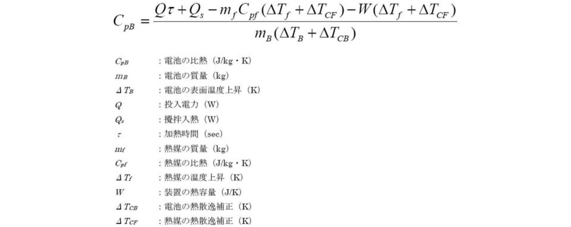
厚さ方向の熱抵抗値は、電池をホットプレートで40℃、55℃、70℃に加熱し、温度の経時変化を3次元熱伝導方程式で再現することで、フィッティングパラメータとして熱伝導率を求めた。熱伝導率の逆数を熱抵抗値として算出した。 (2) Measurement of thermal resistance value in the thickness direction The thermal resistance value in the thickness direction is obtained by heating the battery to 40 ° C, 55 ° C and 70 ° C with a hot plate, and reproducing the change with time in the three-dimensional heat conduction equation. Thus, the thermal conductivity was obtained as a fitting parameter. The reciprocal of thermal conductivity was calculated as the thermal resistance value.

面方向の熱抵抗値は、電池の短辺の端をヒーター2つで挟み、ヒーター温度を40℃、55℃、70℃の3水準で加熱して、ラミネートセルの温度上昇を測定した。厚さ方向の熱抵抗値測定と同様、温度の経時変化を3次元熱伝導方程式で再現し、フィッティングパラメータとして熱伝導率を求め、熱抵抗値を算出した。 (Measurement method of thermal resistance in the surface direction)
The thermal resistance value in the surface direction was measured by increasing the temperature of the laminate cell by sandwiching the end of the short side of the battery with two heaters and heating the heater at three levels of 40 ° C., 55 ° C. and 70 ° C. Similar to the measurement of the thermal resistance value in the thickness direction, the temperature change with time was reproduced by a three-dimensional heat conduction equation, the thermal conductivity was obtained as a fitting parameter, and the thermal resistance value was calculated.
雰囲気温度45℃において、上限電圧を4.15V、下限電圧を2.5Vとして、1C相当の充放電を750サイクルまで繰り返した。 (Measurement method of cycle capacity maintenance rate)
At an atmospheric temperature of 45 ° C., the upper limit voltage was 4.15 V, the lower limit voltage was 2.5 V, and charge / discharge corresponding to 1 C was repeated up to 750 cycles.
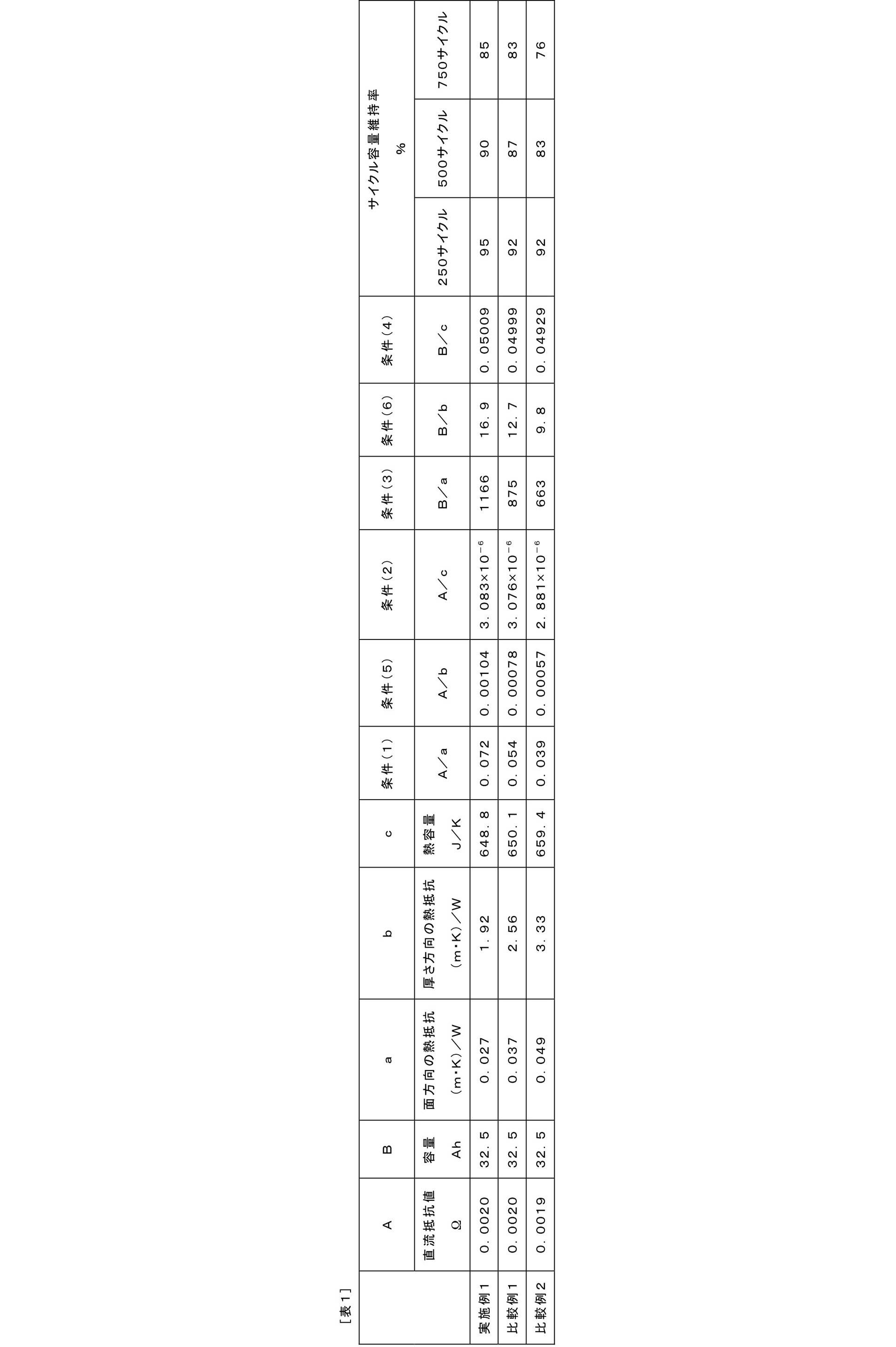
11 負極集電体、
12 正極集電体、
13 負極活物質層、
15 正極活物質層、
17 セパレータ、
19 単電池層、
21、57 発電要素、
25 負極集電板、
27 正極集電板、
29、52 電池外装材、
58 正極タブ、
59 負極タブ。 10, 50 lithium ion secondary battery,
11 negative electrode current collector,
12 positive electrode current collector,
13 negative electrode active material layer,
15 positive electrode active material layer,
17 separator,
19 cell layer,
21, 57 power generation element,
25 negative current collector,
27 positive current collector,
29, 52 Battery exterior material,
58 positive electrode tab,
59 Negative electrode tab.
Claims (6)
- 集電体の表面に、リチウム-ニッケル-マンガン-コバルト複合酸化物を含む正極活物質層が形成されてなる正極と、
電解質層と、
負極と、
が積層されてなる発電要素を有し、
下記条件(1)~(4)の少なくとも1つを満たす、非水電解質二次電池;
(1)電池の直流抵抗[Ω]を電池の面方向の熱抵抗[(m・K)/W]で除した値が0.055以上である;
(2)電池の直流抵抗[Ω]を電池熱容量[J/K]で除した値が3.080×10-6以上である;
(3)電池の容量[Ah]を電池の面方向の熱抵抗[(m・K)/W]で除した値が880以上である;
(4)電池の容量[Ah]を電池熱容量[J/K]で除した値が0.05000以上である。 A positive electrode in which a positive electrode active material layer containing a lithium-nickel-manganese-cobalt composite oxide is formed on the surface of the current collector;
An electrolyte layer;
A negative electrode,
Has a power generation element that is laminated,
A nonaqueous electrolyte secondary battery satisfying at least one of the following conditions (1) to (4);
(1) The value obtained by dividing the direct current resistance [Ω] of the battery by the thermal resistance [(m · K) / W] in the surface direction of the battery is 0.055 or more;
(2) The value obtained by dividing the direct current resistance [Ω] of the battery by the battery heat capacity [J / K] is 3.080 × 10 −6 or more;
(3) A value obtained by dividing the battery capacity [Ah] by the thermal resistance [(m · K) / W] in the surface direction of the battery is 880 or more;
(4) The value obtained by dividing the battery capacity [Ah] by the battery heat capacity [J / K] is 0.05000 or more. - SOC30~50%の全範囲において、上記条件(1)および(2)の少なくとも1つを満たす、請求項1に記載の非水電解質二次電池。 The nonaqueous electrolyte secondary battery according to claim 1, wherein at least one of the conditions (1) and (2) is satisfied in the entire range of SOC 30 to 50%.
- 前記条件(1)~(4)の少なくとも1つに加えて、これ以外の、前記条件(1)~(4)ならびに下記条件(5)および(6)のうちの少なくとも1つを満たす、請求項1または2に記載の非水電解質二次電池;
(5):電池の直流抵抗[Ω]を電池の厚さ方向の熱抵抗[(m・K)/W]で除した値が0.0008以上である;
(6):電池の容量[Ah]を電池の厚さ方向の熱抵抗[(m・K)/W]で除した値が13以上である。 In addition to at least one of the conditions (1) to (4), at least one of the above conditions (1) to (4) and the following conditions (5) and (6) is satisfied: Item 3. The nonaqueous electrolyte secondary battery according to Item 1 or 2;
(5): The value obtained by dividing the direct current resistance [Ω] of the battery by the thermal resistance [(m · K) / W] in the thickness direction of the battery is 0.0008 or more;
(6): The value obtained by dividing the battery capacity [Ah] by the thermal resistance [(m · K) / W] in the thickness direction of the battery is 13 or more. - 前記条件(1)~(4)の少なくとも1つに加えて、前記条件(5)および(6)の少なくとも1つを満たす、請求項3に記載の非水電解質二次電池。 4. The nonaqueous electrolyte secondary battery according to claim 3, wherein, in addition to at least one of the conditions (1) to (4), at least one of the conditions (5) and (6) is satisfied.
- 定格容量に対する電池面積(電池外装体まで含めた電池の投影面積)の比の値が5cm2/Ah以上であり、かつ、定格容量が3Ah以上である、請求項1~4のいずれか1項に記載の非水電解質二次電池。 The value of the ratio of the battery area to the rated capacity (projected area of the battery including the battery outer casing) is 5 cm 2 / Ah or more, and the rated capacity is 3 Ah or more. The non-aqueous electrolyte secondary battery described in 1.
- 矩形状の前記正極活物質層の縦横比として定義される前記正極のアスペクト比は、1~3である、請求項1~5のいずれか1項に記載の非水電解質二次電池。 6. The nonaqueous electrolyte secondary battery according to claim 1, wherein an aspect ratio of the positive electrode, which is defined as an aspect ratio of the rectangular positive electrode active material layer, is 1 to 3.
Priority Applications (5)
| Application Number | Priority Date | Filing Date | Title |
|---|---|---|---|
| CN201580019361.3A CN106170884B (en) | 2014-04-11 | 2015-03-27 | Rechargeable nonaqueous electrolytic battery |
| JP2016512670A JP6187676B2 (en) | 2014-04-11 | 2015-03-27 | Nonaqueous electrolyte secondary battery |
| EP15776377.2A EP3131150A4 (en) | 2014-04-11 | 2015-03-27 | Nonaqueous electrolyte secondary battery |
| KR1020167027693A KR101753023B1 (en) | 2014-04-11 | 2015-03-27 | Nonaqueous electrolyte secondary battery |
| US15/302,865 US10096870B2 (en) | 2014-04-11 | 2015-03-27 | Non-aqueous electrolyte secondary battery |
Applications Claiming Priority (2)
| Application Number | Priority Date | Filing Date | Title |
|---|---|---|---|
| JP2014082257 | 2014-04-11 | ||
| JP2014-082257 | 2014-04-11 |
Publications (1)
| Publication Number | Publication Date |
|---|---|
| WO2015156155A1 true WO2015156155A1 (en) | 2015-10-15 |
Family
ID=54287732
Family Applications (1)
| Application Number | Title | Priority Date | Filing Date |
|---|---|---|---|
| PCT/JP2015/059729 WO2015156155A1 (en) | 2014-04-11 | 2015-03-27 | Nonaqueous electrolyte secondary battery |
Country Status (6)
| Country | Link |
|---|---|
| US (1) | US10096870B2 (en) |
| EP (1) | EP3131150A4 (en) |
| JP (1) | JP6187676B2 (en) |
| KR (1) | KR101753023B1 (en) |
| CN (1) | CN106170884B (en) |
| WO (1) | WO2015156155A1 (en) |
Cited By (1)
| Publication number | Priority date | Publication date | Assignee | Title |
|---|---|---|---|---|
| JP2019160556A (en) * | 2018-03-13 | 2019-09-19 | 三洋電機株式会社 | Nonaqueous electrolyte secondary battery |
Families Citing this family (10)
| Publication number | Priority date | Publication date | Assignee | Title |
|---|---|---|---|---|
| JP6652127B2 (en) * | 2015-03-24 | 2020-02-19 | 日本電気株式会社 | Secondary battery, method of manufacturing secondary battery, electric vehicle, and power storage system |
| JP6979186B2 (en) * | 2017-02-24 | 2021-12-08 | エリーパワー株式会社 | Non-aqueous electrolyte secondary battery and charging method |
| KR102244905B1 (en) * | 2017-07-28 | 2021-04-26 | 주식회사 엘지화학 | Positive electrode for lithium-sulfur battery and lithium-sulfur battery comprising the same |
| CN109802132A (en) * | 2017-11-16 | 2019-05-24 | 中国科学院宁波材料技术与工程研究所 | Positive electrode and preparation method thereof with nanometer rivet arrangement |
| JP6966308B2 (en) * | 2017-12-11 | 2021-11-10 | トヨタ自動車株式会社 | Positive active material for lithium-ion batteries and their manufacturing methods, lithium-ion batteries, and lithium-ion battery systems |
| JP7169763B2 (en) * | 2018-04-09 | 2022-11-11 | 日産自動車株式会社 | Non-aqueous electrolyte secondary battery |
| EP3819979A4 (en) * | 2018-09-14 | 2022-04-13 | Mitsubishi Chemical Corporation | Filling member and battery pack |
| CN114097121A (en) * | 2019-04-30 | 2022-02-25 | 株式会社半导体能源研究所 | Solid-state secondary battery |
| CN113745523A (en) * | 2020-05-29 | 2021-12-03 | 比亚迪股份有限公司 | Lithium ion battery, power battery module, battery pack, electric automobile and energy storage device |
| CN115621532A (en) * | 2022-10-27 | 2023-01-17 | 欣旺达电动汽车电池有限公司 | Secondary battery and power consumption device |
Citations (7)
| Publication number | Priority date | Publication date | Assignee | Title |
|---|---|---|---|---|
| US20070212609A1 (en) * | 2006-03-13 | 2007-09-13 | Sanyo Electric Co., Ltd. | Nonaqueous electrolyte secondary battery |
| JP2010198899A (en) * | 2009-02-25 | 2010-09-09 | Nec Tokin Corp | Lithium ion secondary battery |
| JP2011238416A (en) * | 2010-05-07 | 2011-11-24 | Sumitomo Metal Mining Co Ltd | Positive electrode active material for nonaqueous electrolyte secondary battery and its manufacturing method, and nonaqueous electrolyte secondary battery using positive electrode active material |
| JP2012109125A (en) * | 2010-11-17 | 2012-06-07 | Sony Corp | Nonaqueous electrolyte battery |
| JP2012109124A (en) * | 2010-11-17 | 2012-06-07 | Sony Corp | Nonaqueous electrolyte battery |
| JP2013054973A (en) * | 2011-09-05 | 2013-03-21 | Sony Corp | Separator, nonaqueous electrolyte battery, battery pack, electronic apparatus, electric vehicle, electricity storage device, and electric power system |
| JP2014007034A (en) * | 2012-06-22 | 2014-01-16 | Gs Yuasa Corp | Active material for nonaqueous electrolyte secondary battery, electrode for nonaqueous electrolyte secondary battery, and nonaqueous electrolyte secondary battery |
Family Cites Families (10)
| Publication number | Priority date | Publication date | Assignee | Title |
|---|---|---|---|---|
| KR100412188B1 (en) * | 1998-08-27 | 2003-12-24 | 닛본 덴끼 가부시끼가이샤 | Nonaqueous Electrolyte Secondary Cell |
| AU2003292781A1 (en) * | 2002-12-26 | 2004-07-22 | Fuji Jukogyo Kabushiki Kaisha | Electrical storage device and method for manufacturing electrical storage device |
| US9666862B2 (en) * | 2005-02-23 | 2017-05-30 | Lg Chem, Ltd. | Secondary battery of improved lithium ion mobility and cell capacity |
| JP4211769B2 (en) * | 2005-08-19 | 2009-01-21 | 日産自動車株式会社 | Automotive battery |
| CN101689633A (en) | 2007-05-08 | 2010-03-31 | 加利福尼亚大学董事会 | High-discharge-rate lithium ion battery |
| JP2011054334A (en) | 2009-08-31 | 2011-03-17 | Hitachi Vehicle Energy Ltd | Lithium secondary battery |
| CN102856530B (en) * | 2011-06-30 | 2015-01-21 | 清华大学 | Lithium ion battery |
| CN108470857A (en) * | 2012-06-18 | 2018-08-31 | Nec能源元器件株式会社 | film-covered battery |
| CN104508892A (en) * | 2012-06-28 | 2015-04-08 | 富士重工业株式会社 | Lithium-ion secondary cell |
| KR20160090338A (en) * | 2013-11-27 | 2016-07-29 | 미쓰비시 가가꾸 가부시키가이샤 | Carbon material for negative electrode of nonaqueous rechargeable battery, negative electrode for nonaqueous rechargeable battery, and nonaqueous rechargeable battery |
-
2015
- 2015-03-27 WO PCT/JP2015/059729 patent/WO2015156155A1/en active Application Filing
- 2015-03-27 JP JP2016512670A patent/JP6187676B2/en active Active
- 2015-03-27 EP EP15776377.2A patent/EP3131150A4/en not_active Ceased
- 2015-03-27 US US15/302,865 patent/US10096870B2/en active Active
- 2015-03-27 KR KR1020167027693A patent/KR101753023B1/en active IP Right Grant
- 2015-03-27 CN CN201580019361.3A patent/CN106170884B/en active Active
Patent Citations (7)
| Publication number | Priority date | Publication date | Assignee | Title |
|---|---|---|---|---|
| US20070212609A1 (en) * | 2006-03-13 | 2007-09-13 | Sanyo Electric Co., Ltd. | Nonaqueous electrolyte secondary battery |
| JP2010198899A (en) * | 2009-02-25 | 2010-09-09 | Nec Tokin Corp | Lithium ion secondary battery |
| JP2011238416A (en) * | 2010-05-07 | 2011-11-24 | Sumitomo Metal Mining Co Ltd | Positive electrode active material for nonaqueous electrolyte secondary battery and its manufacturing method, and nonaqueous electrolyte secondary battery using positive electrode active material |
| JP2012109125A (en) * | 2010-11-17 | 2012-06-07 | Sony Corp | Nonaqueous electrolyte battery |
| JP2012109124A (en) * | 2010-11-17 | 2012-06-07 | Sony Corp | Nonaqueous electrolyte battery |
| JP2013054973A (en) * | 2011-09-05 | 2013-03-21 | Sony Corp | Separator, nonaqueous electrolyte battery, battery pack, electronic apparatus, electric vehicle, electricity storage device, and electric power system |
| JP2014007034A (en) * | 2012-06-22 | 2014-01-16 | Gs Yuasa Corp | Active material for nonaqueous electrolyte secondary battery, electrode for nonaqueous electrolyte secondary battery, and nonaqueous electrolyte secondary battery |
Non-Patent Citations (1)
| Title |
|---|
| See also references of EP3131150A4 * |
Cited By (2)
| Publication number | Priority date | Publication date | Assignee | Title |
|---|---|---|---|---|
| JP2019160556A (en) * | 2018-03-13 | 2019-09-19 | 三洋電機株式会社 | Nonaqueous electrolyte secondary battery |
| JP7011499B2 (en) | 2018-03-13 | 2022-02-10 | 三洋電機株式会社 | Non-aqueous electrolyte secondary battery |
Also Published As
| Publication number | Publication date |
|---|---|
| CN106170884B (en) | 2017-09-19 |
| EP3131150A1 (en) | 2017-02-15 |
| US10096870B2 (en) | 2018-10-09 |
| KR20160130829A (en) | 2016-11-14 |
| EP3131150A4 (en) | 2017-08-02 |
| JPWO2015156155A1 (en) | 2017-04-13 |
| KR101753023B1 (en) | 2017-07-03 |
| CN106170884A (en) | 2016-11-30 |
| JP6187676B2 (en) | 2017-08-30 |
| US20170033418A1 (en) | 2017-02-02 |
Similar Documents
| Publication | Publication Date | Title |
|---|---|---|
| JP6187676B2 (en) | Nonaqueous electrolyte secondary battery | |
| JP5967287B2 (en) | Positive electrode active material, positive electrode material, positive electrode and non-aqueous electrolyte secondary battery | |
| JP6036999B2 (en) | Nonaqueous electrolyte secondary battery | |
| JP6112204B2 (en) | Non-aqueous electrolyte secondary battery positive electrode and non-aqueous electrolyte secondary battery using the same | |
| JP6056969B2 (en) | Non-aqueous electrolyte secondary battery | |
| JP6156491B2 (en) | Nonaqueous electrolyte secondary battery | |
| JP6176317B2 (en) | Non-aqueous electrolyte secondary battery positive electrode and non-aqueous electrolyte secondary battery using the same | |
| WO2014133064A1 (en) | Positive electrode active material, positive electrode material, positive electrode, and non-aqueous electrolyte secondary battery | |
| JP6070822B2 (en) | Nonaqueous electrolyte secondary battery | |
| WO2015156400A1 (en) | Positive electrode for electrical device, and electrical device using same | |
| JP6007315B2 (en) | Nonaqueous electrolyte secondary battery | |
| JP6414230B2 (en) | Electrical device | |
| JP6241543B2 (en) | Electrical device | |
| WO2016103509A1 (en) | Electrical device | |
| WO2017212597A1 (en) | Nonaqueous-electrolyte secondary cell | |
| JP6004088B2 (en) | Nonaqueous electrolyte secondary battery | |
| WO2017212596A1 (en) | Nonaqueous electrolyte secondary battery | |
| JP2017073281A (en) | Positive electrode material for nonaqueous electrolyte secondary battery, positive electrode for nonaqueous electrolyte secondary battery using the same, and nonaqueous electrolyte secondary battery | |
| JP2016225185A (en) | Positive electrode for nonaqueous electrolyte secondary battery and nonaqueous electrolyte secondary battery using the same | |
| JP6519264B2 (en) | Positive electrode for non-aqueous electrolyte secondary battery and non-aqueous electrolyte secondary battery using the same | |
| JP2015095330A (en) | Lithium ion secondary battery | |
| JPWO2017212594A1 (en) | Nonaqueous electrolyte secondary battery |
Legal Events
| Date | Code | Title | Description |
|---|---|---|---|
| 121 | Ep: the epo has been informed by wipo that ep was designated in this application |
Ref document number: 15776377 Country of ref document: EP Kind code of ref document: A1 |
|
| ENP | Entry into the national phase |
Ref document number: 2016512670 Country of ref document: JP Kind code of ref document: A |
|
| ENP | Entry into the national phase |
Ref document number: 20167027693 Country of ref document: KR Kind code of ref document: A |
|
| WWE | Wipo information: entry into national phase |
Ref document number: 15302865 Country of ref document: US |
|
| REEP | Request for entry into the european phase |
Ref document number: 2015776377 Country of ref document: EP |
|
| WWE | Wipo information: entry into national phase |
Ref document number: 2015776377 Country of ref document: EP |
|
| NENP | Non-entry into the national phase |
Ref country code: DE |