WO2015146930A1 - Fuel injection device for internal combustion engine - Google Patents
Fuel injection device for internal combustion engine Download PDFInfo
- Publication number
- WO2015146930A1 WO2015146930A1 PCT/JP2015/058783 JP2015058783W WO2015146930A1 WO 2015146930 A1 WO2015146930 A1 WO 2015146930A1 JP 2015058783 W JP2015058783 W JP 2015058783W WO 2015146930 A1 WO2015146930 A1 WO 2015146930A1
- Authority
- WO
- WIPO (PCT)
- Prior art keywords
- fuel
- fuel injection
- pressure
- internal combustion
- cylinder
- Prior art date
Links
Images


Classifications
-
- F—MECHANICAL ENGINEERING; LIGHTING; HEATING; WEAPONS; BLASTING
- F02—COMBUSTION ENGINES; HOT-GAS OR COMBUSTION-PRODUCT ENGINE PLANTS
- F02D—CONTROLLING COMBUSTION ENGINES
- F02D41/00—Electrical control of supply of combustible mixture or its constituents
- F02D41/30—Controlling fuel injection
- F02D41/3011—Controlling fuel injection according to or using specific or several modes of combustion
- F02D41/3076—Controlling fuel injection according to or using specific or several modes of combustion with special conditions for selecting a mode of combustion, e.g. for starting, for diagnosing
-
- F—MECHANICAL ENGINEERING; LIGHTING; HEATING; WEAPONS; BLASTING
- F02—COMBUSTION ENGINES; HOT-GAS OR COMBUSTION-PRODUCT ENGINE PLANTS
- F02D—CONTROLLING COMBUSTION ENGINES
- F02D41/00—Electrical control of supply of combustible mixture or its constituents
- F02D41/02—Circuit arrangements for generating control signals
- F02D41/04—Introducing corrections for particular operating conditions
- F02D41/06—Introducing corrections for particular operating conditions for engine starting or warming up
- F02D41/062—Introducing corrections for particular operating conditions for engine starting or warming up for starting
- F02D41/065—Introducing corrections for particular operating conditions for engine starting or warming up for starting at hot start or restart
-
- F—MECHANICAL ENGINEERING; LIGHTING; HEATING; WEAPONS; BLASTING
- F02—COMBUSTION ENGINES; HOT-GAS OR COMBUSTION-PRODUCT ENGINE PLANTS
- F02D—CONTROLLING COMBUSTION ENGINES
- F02D17/00—Controlling engines by cutting out individual cylinders; Rendering engines inoperative or idling
-
- F—MECHANICAL ENGINEERING; LIGHTING; HEATING; WEAPONS; BLASTING
- F02—COMBUSTION ENGINES; HOT-GAS OR COMBUSTION-PRODUCT ENGINE PLANTS
- F02D—CONTROLLING COMBUSTION ENGINES
- F02D41/00—Electrical control of supply of combustible mixture or its constituents
- F02D41/30—Controlling fuel injection
- F02D41/3094—Controlling fuel injection the fuel injection being effected by at least two different injectors, e.g. one in the intake manifold and one in the cylinder
-
- F—MECHANICAL ENGINEERING; LIGHTING; HEATING; WEAPONS; BLASTING
- F02—COMBUSTION ENGINES; HOT-GAS OR COMBUSTION-PRODUCT ENGINE PLANTS
- F02D—CONTROLLING COMBUSTION ENGINES
- F02D41/00—Electrical control of supply of combustible mixture or its constituents
- F02D41/30—Controlling fuel injection
- F02D41/38—Controlling fuel injection of the high pressure type
- F02D41/3809—Common rail control systems
- F02D41/3836—Controlling the fuel pressure
- F02D41/3845—Controlling the fuel pressure by controlling the flow into the common rail, e.g. the amount of fuel pumped
-
- F—MECHANICAL ENGINEERING; LIGHTING; HEATING; WEAPONS; BLASTING
- F02—COMBUSTION ENGINES; HOT-GAS OR COMBUSTION-PRODUCT ENGINE PLANTS
- F02M—SUPPLYING COMBUSTION ENGINES IN GENERAL WITH COMBUSTIBLE MIXTURES OR CONSTITUENTS THEREOF
- F02M61/00—Fuel-injectors not provided for in groups F02M39/00 - F02M57/00 or F02M67/00
- F02M61/14—Arrangements of injectors with respect to engines; Mounting of injectors
- F02M61/145—Arrangements of injectors with respect to engines; Mounting of injectors the injection nozzle opening into the air intake conduit
-
- F—MECHANICAL ENGINEERING; LIGHTING; HEATING; WEAPONS; BLASTING
- F02—COMBUSTION ENGINES; HOT-GAS OR COMBUSTION-PRODUCT ENGINE PLANTS
- F02N—STARTING OF COMBUSTION ENGINES; STARTING AIDS FOR SUCH ENGINES, NOT OTHERWISE PROVIDED FOR
- F02N99/00—Subject matter not provided for in other groups of this subclass
- F02N99/002—Starting combustion engines by ignition means
- F02N99/006—Providing a combustible mixture inside the cylinder
-
- F—MECHANICAL ENGINEERING; LIGHTING; HEATING; WEAPONS; BLASTING
- F02—COMBUSTION ENGINES; HOT-GAS OR COMBUSTION-PRODUCT ENGINE PLANTS
- F02D—CONTROLLING COMBUSTION ENGINES
- F02D41/00—Electrical control of supply of combustible mixture or its constituents
- F02D41/30—Controlling fuel injection
- F02D41/38—Controlling fuel injection of the high pressure type
- F02D41/3809—Common rail control systems
- F02D2041/3881—Common rail control systems with multiple common rails, e.g. one rail per cylinder bank, or a high pressure rail and a low pressure rail
-
- F—MECHANICAL ENGINEERING; LIGHTING; HEATING; WEAPONS; BLASTING
- F02—COMBUSTION ENGINES; HOT-GAS OR COMBUSTION-PRODUCT ENGINE PLANTS
- F02D—CONTROLLING COMBUSTION ENGINES
- F02D41/00—Electrical control of supply of combustible mixture or its constituents
- F02D41/30—Controlling fuel injection
- F02D41/38—Controlling fuel injection of the high pressure type
- F02D2041/389—Controlling fuel injection of the high pressure type for injecting directly into the cylinder
-
- F—MECHANICAL ENGINEERING; LIGHTING; HEATING; WEAPONS; BLASTING
- F02—COMBUSTION ENGINES; HOT-GAS OR COMBUSTION-PRODUCT ENGINE PLANTS
- F02D—CONTROLLING COMBUSTION ENGINES
- F02D2200/00—Input parameters for engine control
- F02D2200/02—Input parameters for engine control the parameters being related to the engine
- F02D2200/04—Engine intake system parameters
- F02D2200/0406—Intake manifold pressure
-
- F—MECHANICAL ENGINEERING; LIGHTING; HEATING; WEAPONS; BLASTING
- F02—COMBUSTION ENGINES; HOT-GAS OR COMBUSTION-PRODUCT ENGINE PLANTS
- F02D—CONTROLLING COMBUSTION ENGINES
- F02D2200/00—Input parameters for engine control
- F02D2200/02—Input parameters for engine control the parameters being related to the engine
- F02D2200/04—Engine intake system parameters
- F02D2200/0414—Air temperature
-
- F—MECHANICAL ENGINEERING; LIGHTING; HEATING; WEAPONS; BLASTING
- F02—COMBUSTION ENGINES; HOT-GAS OR COMBUSTION-PRODUCT ENGINE PLANTS
- F02D—CONTROLLING COMBUSTION ENGINES
- F02D2200/00—Input parameters for engine control
- F02D2200/02—Input parameters for engine control the parameters being related to the engine
- F02D2200/06—Fuel or fuel supply system parameters
- F02D2200/0602—Fuel pressure
-
- F—MECHANICAL ENGINEERING; LIGHTING; HEATING; WEAPONS; BLASTING
- F02—COMBUSTION ENGINES; HOT-GAS OR COMBUSTION-PRODUCT ENGINE PLANTS
- F02D—CONTROLLING COMBUSTION ENGINES
- F02D41/00—Electrical control of supply of combustible mixture or its constituents
- F02D41/02—Circuit arrangements for generating control signals
- F02D41/04—Introducing corrections for particular operating conditions
- F02D41/042—Introducing corrections for particular operating conditions for stopping the engine
-
- F—MECHANICAL ENGINEERING; LIGHTING; HEATING; WEAPONS; BLASTING
- F02—COMBUSTION ENGINES; HOT-GAS OR COMBUSTION-PRODUCT ENGINE PLANTS
- F02N—STARTING OF COMBUSTION ENGINES; STARTING AIDS FOR SUCH ENGINES, NOT OTHERWISE PROVIDED FOR
- F02N11/00—Starting of engines by means of electric motors
- F02N11/08—Circuits or control means specially adapted for starting of engines
- F02N11/0814—Circuits or control means specially adapted for starting of engines comprising means for controlling automatic idle-start-stop
-
- F—MECHANICAL ENGINEERING; LIGHTING; HEATING; WEAPONS; BLASTING
- F02—COMBUSTION ENGINES; HOT-GAS OR COMBUSTION-PRODUCT ENGINE PLANTS
- F02N—STARTING OF COMBUSTION ENGINES; STARTING AIDS FOR SUCH ENGINES, NOT OTHERWISE PROVIDED FOR
- F02N2200/00—Parameters used for control of starting apparatus
- F02N2200/02—Parameters used for control of starting apparatus said parameters being related to the engine
- F02N2200/021—Engine crank angle
-
- Y—GENERAL TAGGING OF NEW TECHNOLOGICAL DEVELOPMENTS; GENERAL TAGGING OF CROSS-SECTIONAL TECHNOLOGIES SPANNING OVER SEVERAL SECTIONS OF THE IPC; TECHNICAL SUBJECTS COVERED BY FORMER USPC CROSS-REFERENCE ART COLLECTIONS [XRACs] AND DIGESTS
- Y02—TECHNOLOGIES OR APPLICATIONS FOR MITIGATION OR ADAPTATION AGAINST CLIMATE CHANGE
- Y02T—CLIMATE CHANGE MITIGATION TECHNOLOGIES RELATED TO TRANSPORTATION
- Y02T10/00—Road transport of goods or passengers
- Y02T10/10—Internal combustion engine [ICE] based vehicles
- Y02T10/12—Improving ICE efficiencies
Definitions
- the present disclosure relates to a fuel injection device for an internal combustion engine mounted on a vehicle having a so-called idle stop function for forcibly stopping engine idling when the vehicle is temporarily stopped.
- a fuel injection control means of an internal combustion engine equipped in a vehicle it is provided with an in-cylinder injector for injecting fuel into a cylinder and an intake passage injector for injecting fuel into an intake port, and a cylinder according to an operating state.
- a multi-point injection type fuel injection device that controls fuel injection from an inner injector and fuel injection from an intake passage injector is known.
- accelerator response and fuel efficiency are improved, and exhaust gas can be purified.
- This fuel injection device injects fuel into the intake passage in the low load and low rotation region, thereby improving the mixing characteristics of the intake air and the fuel and improving the ignition performance. In the high load and high rotation region, the fuel injection device starts from the intake passage injector.
- the fuel injection and the fuel injection from the in-cylinder injector are used in combination.
- Patent Document 1 discloses a hybrid vehicle including an in-cylinder fuel supply passage having an in-cylinder injector, an intake passage fuel supply passage having an intake passage injector, and an internal combustion engine having idle stop means.
- This hybrid vehicle discloses means for keeping the fuel pressure (fuel pressure) high by closing the relief valve of the in-cylinder fuel supply path at the time of idling stop.
- Patent Documents 2 and 3 when the idle stop condition is released after the idle stop, the fuel pump is driven before the engine is restarted, and the fuel pressure in the fuel supply path is started before the engine is restarted.
- An internal combustion engine for a vehicle having control means for raising the fuel pressure to a required level is disclosed.
- the fuel pump does not operate while the engine is stopped, the fuel pressure in the fuel supply path is lowered, and therefore, fuel injection into the cylinder is delayed, and there is a case where the engine cannot be started quickly when the engine is restarted.
- Patent Document 1 does not disclose means for preventing the occurrence of knocking at the time of restart after idle stop.
- fuel is injected into the cylinder without measuring the fuel pressure in the in-cylinder fuel supply path at the restart after the idle stop, there is a possibility that the fuel cannot be injected into the cylinder in a relatively high pressure state. Therefore, there is a possibility that quick restart cannot be performed.
- fuel is uniformly injected into a plurality of cylinders and the stop state at the time of idling stop of each cylinder is not considered, when fuel is injected into a cylinder stopped in the exhaust stroke, unburned fuel is exhausted. There is a possibility that the exhaust gas properties are deteriorated due to being discharged into the passage.
- control means disclosed in Patent Documents 2 and 3 require time for raising the fuel pressure in the fuel supply path to the fuel pressure necessary for starting after the idle stop condition is canceled, and quick starting is not possible. There is a problem.
- the present invention has been made in view of the above-described problems, and an object of at least one embodiment of the present invention is to perform a quick restart after an idle stop, and eliminate the occurrence of knocking at the time of restart. It is to prevent deterioration of drivability and NVH immediately after starting.
- a fuel injection device for an internal combustion engine includes a first fuel injection means for injecting fuel into a cylinder of the internal combustion engine, and a second for injecting fuel into an intake passage of the internal combustion engine.
- a fuel injection device for an internal combustion engine having fuel injection means and automatic restart means for automatically restarting the internal combustion engine. Fuel remaining in the first fuel injection means when the internal combustion engine is automatically restarted. And a fuel injection control means for automatically restarting the internal combustion engine before starting the rotation of the crankshaft and starting fuel injection from the second fuel injection means when a predetermined condition is satisfied.
- the fuel injection control means performs only fuel injection into the cylinder by the first fuel injection means at the time of restart. This reduces the amount of intake air supplied into the cylinder and cools the cylinder with the cooling action of the injected fuel, thereby suppressing an increase in the compression pressure in the cylinder and eliminating the occurrence of knocking. Start is possible.
- the fuel injection from the second fuel injection means is switched to, or the fuel injection from the first fuel injection means and the second fuel injection means is used in combination.
- Such multi-point injection of fuel can promote premixing at the time of a small intake amount and prevent deterioration of exhaust gas properties at the time of restart.
- the fuel injection control means injects the remaining fuel in the first fuel injection means before the start of rotation of the crankshaft by the starter.
- fuel can be injected from the first fuel supply path into the cylinder having a low in-cylinder pressure before the rotation of the crankshaft is started (that is, before the operation of the piston is started).
- the configuration of (1) further includes a crank angle sensor that measures a crank angle of the internal combustion engine and detects a stroke of the internal combustion engine. It is included that it is detected that a predetermined number of strokes have elapsed after restart.
- the fuel is injected by the first fuel injection means from the initial explosion at the time of restart until several combustion cycles are performed.
- the occurrence of knocking at the time of restart can be reliably prevented, and drivability and NVH can be improved.
- the configuration of (2) further includes an intake pressure sensor that measures the intake pressure in the intake passage, and the detection value of the intake pressure sensor is a predetermined intake pressure value in the predetermined condition. It is characterized by including the following. By adding that the intake pressure is equal to or lower than a predetermined intake pressure value as the predetermined condition, knocking can be reliably prevented during restart, and drivability and NVH can be improved. Furthermore, pre-mixing at a small intake amount can be promoted by multi-point injection of fuel, and deterioration of exhaust gas properties at the time of restart can be prevented.
- an intake air temperature sensor that measures the temperature of the intake air in the intake passage is further provided, and the fuel injection control unit responds to a detection result of the intake air temperature sensor.
- the fuel injection from the second fuel injection means is started by varying the predetermined number of strokes. This can more reliably prevent the occurrence of knocking at the time of restart.
- the internal combustion engine further includes a fuel pressure sensor that measures a fuel pressure of the first fuel injection unit, and the fuel The injection control means selects a cylinder having an in-cylinder pressure capable of injecting fuel remaining in the first fuel injection means in accordance with a measurement value of the fuel pressure sensor, and remains in the first fuel injection means in the selected cylinder. The fuel is injected.
- the fuel injection control means performs only fuel injection into the cylinder by the first fuel injection means at the time of restart. At that time, the fuel pressure of the fuel remaining in the first fuel injection means is measured by the fuel pressure sensor, a cylinder having an in-cylinder pressure capable of injecting the fuel remaining in the first fuel injection means is selected, and the first cylinder is selected as the selected cylinder. The remaining fuel is injected into the fuel injection means.
- the fuel remaining in the first fuel injection means is injected into the cylinder, and the inside of the cylinder can be cooled by the cooling action of the injected fuel while suppressing the amount of intake air supplied to the cylinder. Therefore, the increase in the compression pressure in the cylinder can be eliminated and the occurrence of knocking can be prevented, so that it is possible to prevent drivability immediately after starting, deterioration of NVH, and deterioration of exhaust gas properties.
- the air-fuel ratio can be kept low by the fuel injection from the first fuel injection means, the ignition performance is improved and the fuel can be quickly supplied to the cylinder without waiting for the operation of the fuel pump. Thus, a quick restart after an idle stop is possible.
- the fuel pressure in the first fuel supply passage is measured, and a cylinder having an in-cylinder pressure capable of injecting fuel remaining in the first fuel supply passage is selected by the fuel injection control means, and fuel is injected into the selected cylinder. By doing so, fuel injection into the cylinder can be reliably performed.
- the fuel injection control means stops when the fuel pressure of the first fuel injection means is equal to or higher than a first threshold value in the compression stroke.
- the first cylinder is selected and the fuel pressure of the first fuel injection means is equal to or higher than the second threshold value lower than the first threshold value
- the second cylinder stopped in the first half of the intake stroke or the compression stroke is selected.
- the third cylinder stopped immediately before the intake stroke or in the first half of the intake stroke is selected, and the fuel injection control means
- fuel injection is started from the first cylinder from the first fuel injection means.
- the first cylinder stopped in the compression stroke is selected by the fuel injection control means, and the first fuel injection is made to the first cylinder.
- the fuel remaining in the means is injected.
- the second cylinder stopped in the region of the intake stroke (preferably, the latter half of the intake stroke) or the first half of the compression stroke is selected.
- the fuel remaining in the first fuel injection means is injected into the second cylinder.
- a third cylinder stopped immediately before the intake stroke or in the first half of the intake stroke is selected, and this third cylinder is used as the first fuel injection means. Inject remaining fuel.
- the first threshold value and the second threshold value are set based on the fuel pressure that enables fuel injection in relation to the in-cylinder pressure of the cylinder into which fuel is injected simultaneously with the restart of the engine.
- the fuel pressure of the fuel remaining in the first fuel injection means is equal to or higher than the first threshold
- the fuel is quickly injected by injecting the fuel into the cylinder stopped in the compression stroke. It is possible to shift to the combustion stroke, and quick restart is possible.
- the fuel pressure of the residual fuel does not reach the first threshold value
- the residual fuel is injected into the cylinder stopped in the region of the intake stroke (preferably the latter half of the intake stroke) or the first half of the compression stroke, so that the fuel into the cylinder is injected.
- an automatic stop unit that automatically stops the internal combustion engine when a predetermined condition is satisfied
- the first fuel injection unit A high-pressure fuel pump for sending fuel to the fuel injection control means, wherein the fuel injection control means is configured to stop the automatic stop when the predetermined condition for the automatic stop is satisfied during operation of the internal combustion engine by the second fuel injection means.
- the high-pressure fuel pump is operated to increase the fuel pressure remaining in the first fuel injection means.
- the internal combustion engine is stopped by the automatic stop means when the first predetermined condition, that is, the idle stop condition is satisfied during the operation by the second fuel injection means in the low load region.
- the high pressure fuel pump is operated before, and the fuel pressure of the first fuel injection means is increased.
- the fuel remaining in the first fuel supply path is discharged into the cylinder until the combustion cycle is performed several times after the initial explosion at the time of restart or before the start of rotation of the crankshaft by the starter.
- the inside of the cylinder can be cooled with the injected fuel while suppressing the amount of intake air supplied to the cylinder. Therefore, the increase in the compression pressure in the cylinder can be eliminated, the occurrence of knocking can be prevented, and the drivability immediately after starting, the deterioration of NVH, and the deterioration of exhaust gas properties can be prevented. Further, since the air-fuel ratio can be kept low by the fuel injection from the first fuel injection means rather than the fuel injection from the second fuel injection means, the ignition performance can be improved.
- fuel can be injected into the cylinder without waiting for the operation of the fuel pump, so that a quick start is possible and the fuel pump is not operated during this time, so that the pump drive friction can be reduced. Fuel consumption can be reduced.
- a fuel pressure sensor that measures a pressure of fuel supplied to the first fuel injection unit
- the fuel injection control unit includes a fuel pressure sensor.
- the fuel injection control means stops the second fuel injection means and stops the internal combustion engine when the measured value of the fuel pressure sensor is equal to or higher than a predetermined pressure value.
- the pump drive friction can be reduced while maintaining the high residual fuel pressure of the first fuel injection means.
- the residual fuel pressure of the first fuel injection means is secured at the time of restart by operating the high-pressure fuel pump until the rotation of the internal combustion engine stops. can do.
- the fuel injection control unit is operated using the second fuel injection unit at a low load of the internal combustion engine.
- the fuel and intake air are uniformly mixed in the low load region, and good combustion can be maintained in the low load region, and the high pressure fuel pump is operated in the operation in the low load region. Therefore, pump drive friction can be reduced.
- fuel can be injected into the cylinder using the fuel pressure of the first fuel supply system, thereby enabling quick restart without occurrence of knocking, While enabling good drivability immediately after start-up, deterioration of exhaust gas properties and NVH can be prevented.
- an expression indicating that things such as “identical”, “equal”, and “homogeneous” are in an equal state not only represents an exactly equal state, but also has a tolerance or a difference that can provide the same function. It also represents the existing state.
- expressions representing shapes such as quadrangular shapes and cylindrical shapes represent not only geometrically strict shapes such as quadrangular shapes and cylindrical shapes, but also irregularities and chamfers as long as the same effects can be obtained. A shape including a part or the like is also expressed.
- the expressions “comprising”, “comprising”, “comprising”, “including”, or “having” one constituent element are not exclusive expressions for excluding the existence of other constituent elements.
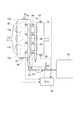
- a gasoline drive engine (hereinafter referred to as “engine”) 10 mounted on a vehicle is an in-line four-cylinder engine having a plurality of, that is, four cylinders 12a to 12d.
- the intake manifold 14 is connected to a surge tank 22.
- An intake valve 18 is provided at the outlet of the intake manifold 14, and an exhaust valve 20 is provided at the inlet of the exhaust manifold 16.
- the surge tank 22 is provided with an intake pressure sensor (MAP sensor) 24 that measures the pressure of intake air and an intake air temperature sensor 26 that measures the temperature of intake air.
- MAP sensor intake pressure sensor
- a piston 28 that reciprocates by combustion in the combustion chamber c is provided, and in each cylinder 12a to 12d, a crank chamber 30 that houses a crankshaft 32 is provided. Outside the crank chamber 30, a starter 34 that rotates the crankshaft 32 when the engine is started, a crank angle sensor 36 that measures the crank angle, and a rotation speed sensor 37 that measures the rotation speed of the crankshaft 32 are provided.
- the fuel stored in the fuel tank 38 is discharged to a low-pressure fuel supply pipe 42 by a low-pressure fuel pump 40 built in the fuel tank 38.
- the low-pressure fuel supply pipes 42 are connected to individual intake passages of the intake manifold 14 via low-pressure fuel distribution pipes 48.
- An intake passage injector 46 is provided at a connection portion between the low pressure fuel supply pipe 42 and the intake passage of the intake manifold 14.
- the low-pressure fuel supply pipe 42 and the intake passage injector 46 constitute a low-pressure fuel system (second fuel injection means).
- One flow path of the low-pressure fuel supply pipe 42 is connected to a high-pressure fuel supply pipe 53 and a high-pressure fuel distribution pipe 54 via a high-pressure fuel pump 50.
- the high-pressure fuel distribution pipe 54 is connected to each cylinder 12a to 12d, and an in-cylinder injector 44 is provided at a connection portion with each cylinder.
- the fuel discharged to the low-pressure fuel supply pipe 42 by the low-pressure fuel pump 40 is sent to the high-pressure fuel pump 50 and supplied to each intake passage of the intake manifold 14 via the low-pressure fuel distribution pipe 48 via the intake passage injector 46. Is done.
- the cam mechanism 52 opens and closes the intake valve 18 and the exhaust valve 20 in conjunction with the crankshaft 32.
- the high-pressure fuel pump 50 supplies fuel to the high-pressure fuel distribution pipe 54 in conjunction with the cam mechanism 52, and the fuel supply is controlled by a command from the ECU 60 described later.
- the fuel sent to the high-pressure fuel pump 50 becomes high pressure by the high-pressure fuel pump 50 and is supplied to each cylinder 12a to 12d via the high-pressure fuel supply pipe 53 and the high-pressure fuel distribution pipe (high-pressure delivery pipe) 54. 44 is injected into the combustion chamber c of each cylinder.
- the high-pressure fuel distribution pipe 54 is provided with a fuel pressure sensor 56 for measuring the fuel pressure.
- the in-cylinder injector 44, the high-pressure fuel pump 50, the high-pressure fuel supply pipe 53, and the high-pressure fuel distribution pipe 54 constitute a high-pressure fuel system (first fuel injection means).
- the vehicle on which the engine 10 is mounted is provided with an in-vehicle battery 58 and an engine control unit (ECU) 60 that controls driving of the engine 10.
- ECU engine control unit
- the driver operates the ignition switch 62
- the ECU 60 starts operating.
- electric power is supplied from the in-vehicle battery 58 to the low-pressure fuel pump 40 via the relay 64, and the low-pressure fuel pump 40 operates.
- the operation of the spark plug 66, the in-cylinder injector 44, and the intake passage injector 46 is controlled by a command from the ECU 60.
- the ECU 60 includes an idle stop / start unit 68 and a fuel injection control unit 70.
- the ECU 60 receives measured values of the intake pressure sensor 24, the intake air temperature sensor 26, the crank angle sensor 36, the rotation speed sensor 37, and the fuel pressure sensor 56.
- the idle stop / start 68 controls the operation of the spark plug 66, the starter 34, etc., the vehicle speed becomes zero, the brake is depressed, the accelerator operation amount is zero, and the lever is set to the driving range.
- the idle stop condition such as is satisfied, the engine 10 is stopped. Further, when the idle stop condition is canceled, the engine 10 is restarted.
- the fuel injection control unit 70 operates the in-cylinder injector 44, the intake passage injector 46, and the spark plug 66 during restart when the engine 10 is stopped when the idle stop condition is satisfied and then the idle stop condition is canceled. Control.
- the fuel injection control unit 70 includes cylinder selection units 72 and 73.
- the cylinder selection units 72 and 73 detect the crank angle sensor 36 input to the ECU 60 when restarting after the release of the idle stop condition.
- a cylinder having a compression stroke, a cylinder having an intake stroke, and the like are selected based on the value, a cylinder that can be supplied according to the fuel pressure of the fuel remaining in the high pressure fuel distribution pipe 54 is selected, and an in-cylinder injector is connected to the selected cylinder. Fuel is sequentially injected from 44.
- FIG. 3 shows the crank angle when each cylinder 12a to 12d is stopped.
- S10 crank angle sensor 36
- FIG. 4 shows the correlation between the crank angle and the stroke in the combustion cycle of each of the cylinders 12a to 12d (in-line four cylinders). The ignition sequence is ignited in the order of 12a, 12c, 12d, and 12b.
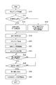
- the fuel injection control unit 70 determines whether or not the measured value (fuel pressure at the time of engine restart) measured by the fuel pressure sensor 56 is equal to or greater than a preset threshold value (S12).
- the threshold value predetermined pressure value
- the threshold value is appropriately set so that a change in the in-cylinder pressure at the time of automatic stop is obtained in advance by experimental data and the fuel pressure at which fuel can be injected is obtained using the in-cylinder pressure as a guide. If the measured value is equal to or greater than the threshold value, the cylinder in which the piston 28 is stopped in the compression stroke region is selected, and the fuel remaining in the high-pressure fuel distribution pipe 54 is injected into the selected cylinder through the in-cylinder injector 44. (S14 ⁇ S18). If the fuel can be injected in the compression stroke in the middle of the increase of the in-cylinder pressure, the time until combustion in the next combustion stroke is short, so that restarting is possible at an early stage.
- the cylinder in which the piston 28 is stopped in the second half of the intake stroke or the first half of the compression stroke is selected, and the fuel remaining in the high-pressure fuel distribution pipe 54 is selected in the selected cylinder. Injection is performed through the in-cylinder injector 44 (S16 ⁇ S18). These cylinders are selected by a cylinder selection unit 72.
- the starter 34 operates to start cranking (S20). Further, the relay 64 is turned on by a command from the ECU 60, the electric power of the vehicle-mounted battery 58 is supplied to the low-pressure fuel pump 40, and the low-pressure fuel pump 40 starts operating. Simultaneously with the start of cranking, the cam mechanism 52 is operated in conjunction with the crankshaft 32, and the intake valve 18 and the exhaust valve 20 are operated by the operation of the cam mechanism 52. Further, along with the start of the operation of the low-pressure fuel pump 40, the high-pressure fuel pump 50 starts operating in conjunction with the cam mechanism 52 (S22).
- the ignition plug 66 is actuated by a command from the ECU 60, the fuel injected into the cylinder is ignited in S18, and the combustion stroke is started (S24).
- the processes from S18 to S24 are performed in a very short time.
- the fuel supplied from the fuel tank 38 is injected from the high-pressure fuel distribution pipe 54 into the cylinders 12a to 12d via the in-cylinder injector 44 according to a command from the ECU 60. .
- the number of combustion cycles after restart is measured by the rotational speed sensor 37, and the combustion cycle is performed, for example, 2 to 5 times, for the set number of times (S26).
- One combustion cycle is four strokes of intake, compression, combustion (expansion), and exhaust, and the number of strokes is 8 to 20 in 2 to 5 combustion cycles.
- the ECU 60 stops the fuel injection from the high pressure fuel distribution pipe 54 and the fuel injection from the low pressure fuel distribution pipe 48 is performed. Switching (S30). Thereafter, the operation of the high-pressure fuel pump 50 is stopped (S32). The operation of the high pressure fuel distribution pipe 54 may be continued, and the fuel pressure injection from the high pressure fuel distribution pipe 54 and the fuel pressure injection from the low pressure fuel distribution pipe 48 may be used in combination.
- a threshold value predetermined intake pressure value
- a method for selecting a cylinder for injecting fuel from the high-pressure fuel distribution pipe 54 at the time of restart performed by the cylinder selection unit 72 will be specifically described.
- the fuel pressure in the high-pressure fuel distribution pipe 54 is equal to or greater than the threshold value and the stop crank angle when the engine is stopped is in the regions A and B, fuel can be supplied into the cylinder even during the compression stroke. Therefore, when the stop crank angle is in the regions C and D, fuel is injected into the cylinder 12b.
- the fuel remaining in the high-pressure fuel distribution pipe 54 is injected into the cylinder using the fuel pressure and supplied to the cylinder. Since the inside of the cylinder can be cooled by the cooling action of the injected fuel while suppressing the intake air amount, occurrence of knocking can be prevented. As a result, it is possible to prevent deterioration of drivability and NVH immediately after start-up and deterioration of exhaust gas properties.
- the fuel increase during the automatic restart can be kept low. That is, when the injection of the intake passage injector 46 is used at the time of automatic restart, the fuel adhering to the intake port or the like increases when the pressure of the intake manifold 14 becomes close to the atmospheric pressure. Therefore, when the fuel is injected from the intake passage injector 46 during the automatic restart, a larger amount of fuel is required than the injection from the in-cylinder injector 44 in order to secure the amount of fuel supplied into the cylinder. On the other hand, in the case of injection from the in-cylinder injector 44, it is not necessary to consider the fuel adhering to the intake port or the like. Therefore, automatic restart can be performed with a smaller amount of fuel compared to the injection of the intake passage injector 46, and fuel consumption (fuel consumption) can be suppressed.
- the residual fuel can be supplied to the selected cylinder without waiting for the operation of the low pressure fuel pump 40 and the high pressure fuel pump 50, quick restart is possible, and during this time, the low pressure fuel pump 40 and the high pressure fuel pump 50 are provided. Since the engine is not operated, the pump drive friction can be reduced, and by suppressing the combustion pressure required at the time of start-up, the amount of fuel necessary for combustion can be reduced and fuel consumption can be suppressed.
- the number of combustion cycles is measured by the rotational speed sensor 37, the number of combustion cycles reaches the set number, and the pressure of the surge tank 22 is measured by the intake pressure sensor 24, and the measured value of the intake pressure sensor 24 is obtained. Since the fuel injection from the low-pressure fuel distribution pipe 48 is switched after the threshold value is reached, the pressure of the intake manifold 14 changes from the atmospheric pressure state to the negative pressure, and the atomization of the fuel injected from the intake passage injector 46 is promoted. When the environment to be established is established, the injection from the intake passage injector 46 can be started.
- the fuel injected from the intake passage injector 46 is supplied into the cylinder in the form of droplets, so that the combustion is prevented from deteriorating and the exhaust gas is prevented from being deteriorated. NVH deterioration due to fluctuations in pressure can be suppressed. In addition, there is no possibility that the compression pressure increases in the cylinder and knocking occurs. Furthermore, since the switching timing is set based on the two measured values of the fuel pressure sensor 56 and the intake pressure sensor 24, the switching timing that can prevent the occurrence of knocking can be optimized.
- a threshold value is set for the measurement value of the fuel pressure sensor 56, and when the measurement value is equal to or greater than the threshold value, fuel can be injected into a cylinder whose stop crank angle is in the compression stroke, so that the combustion stroke can be quickly performed. Restart is possible. Further, when the measured value does not reach the threshold value, fuel is injected into the cylinder in the second half of the intake stroke or the first half of the compression stroke where the in-cylinder pressure is low, so that even when the fuel pressure is low, the fuel can be easily injected into the cylinder. Become.
- the fuel injection is switched from the in-cylinder injector 44 to the intake passage injector 46 in S30, but the in-cylinder injector 44 and the fuel injection from the in-cylinder injector 44 are not stopped in S30. Fuel injection may be performed from both of the intake passage injectors 46. As a result, the restart can be performed reliably.
- the intake air temperature sensor 26 measures the intake air temperature, and according to this measured value, The number of combustion cycles (number of strokes) to be switched from the in-cylinder injector 44 to the intake passage injector 46 is varied (S25). Other operation procedures (S10 to S24 and S26 to S32) are the same as those in the first embodiment. Further, the apparatus configuration such as the engine and ECU and other operation procedures for releasing the idle stop are the same as those in the first embodiment.
- the temperature of the intake air passing through the intake manifold 14 is measured by the intake air temperature sensor 26, and the number of combustion cycles (the number of strokes) to be switched from the in-cylinder injector 44 to the intake passage injector 46 is varied according to the intake air temperature. ing. That is, as the intake air temperature is higher, knocking at the time of start-up is more likely to occur, and the probability that knocking will occur during combustion when being injected from the intake passage injector 46 is increased. Therefore, the number of combustion cycle strokes is increased to, for example, 6 to 10 combustion cycles in accordance with the measured intake air temperature, and after obtaining the in-cylinder cooling action by the injection from the in-cylinder injector 44, the injection from the intake passage injector 46 is performed. Has started.
- FIG. 7 shows the crank angle when each cylinder 12a to 12d is stopped.
- FIG. 4 shows the correlation between the crank angle and the stroke in the combustion cycle of each of the cylinders 12a to 12d (in-line four cylinders). The ignition sequence is ignited in the order of 12a, 12c, 12d, and 12b.
- the fuel injection control unit 70 determines whether or not the fuel pressure of the high-pressure fuel distribution pipe 54 measured by the fuel pressure sensor 56 (fuel pressure at the time of engine restart) is equal to or higher than a first threshold set in advance (S42). ).
- the first threshold value is set based on the fuel pressure at which fuel can be injected from the high-pressure fuel distribution pipe 54 into the cylinder stopped in the compression stroke region. If the measured value of the fuel pressure sensor 56 is equal to or greater than the first threshold value, the first cylinder in which the piston 28 is stopped in the compression stroke is selected, and the fuel remaining in the high-pressure fuel distribution pipe 54 is selected in the first cylinder.
- the fuel pressure is used to inject from the in-cylinder injector 44 (S44 ⁇ S52).
- the piston 28 is stopped in the second half of the intake stroke or the first half of the compression stroke.
- a second cylinder is selected (S48).
- the fuel remaining in the high-pressure fuel distribution pipe 54 is injected into the second cylinder from the in-cylinder injector 44 using the fuel pressure (S52).
- the second threshold value is set with a fuel pressure lower than the first threshold value and a fuel pressure capable of injecting fuel into the cylinder stopped in the second half of the intake stroke or the first half of the compression stroke.
- the third cylinder stopped immediately before the intake stroke or in the first half of the intake stroke is selected, and the low-pressure fuel distribution pipe 48 is connected to the intake passage of the third cylinder. Then, the fuel is supplied through the intake passage injector 46 (S50). These cylinders are selected by a cylinder selection unit 73.
- fuel injection from the high pressure fuel distribution pipe 54 to the second cylinder and fuel injection from the low pressure fuel distribution pipe 48 to the intake passage of the third cylinder may be used in combination. .
- the ratio of the fuel injection amount is such that the fuel injection amount from the low pressure fuel distribution pipe 48 is larger than the fuel injection amount from the high pressure fuel distribution pipe 54.
- the ratio of the fuel injection amount from the low pressure fuel distribution pipe 48 to the fuel injection amount from the high pressure fuel distribution pipe 54 is set to 6: 4 or 7: 3.
- the starter 34 operates to rotate the crankshaft 32 and start cranking (S54).
- the relay 64 is turned on by a command from the ECU 60, the electric power of the in-vehicle battery 58 is supplied to the low-pressure fuel pump 40, and the low-pressure fuel pump 40 starts operating.
- the cam mechanism 52 operates in conjunction with the crankshaft 32, the intake valve 18 and the exhaust valve 20 operate in conjunction with the cam mechanism 52, and the high-pressure fuel pump 50 starts operating ( S56).
- the spark plug 66 is actuated by a command from the ECU 60, the fuel injected into the cylinder is ignited in S52, and the combustion stroke is started (S58).
- the processes from S54 to S58 are performed in a very short time.
- the fuel supplied from the fuel tank 38 is injected from the high-pressure fuel distribution pipe 54 into the cylinders 12a to 12d via the in-cylinder injector 44 according to a command from the ECU 60.
- the The number of combustion cycles after restart is measured by the rotational speed sensor 37, and the combustion cycle is performed, for example, 2 to 5 times, for the set number of times (S60).
- the ECU 60 stops the fuel injection from the high pressure fuel distribution pipe 54 and switches to the fuel injection from the low pressure fuel distribution pipe 48 (S64).
- the operation of the high-pressure fuel pump 50 is stopped (S66).
- the operation of the high-pressure fuel distribution pipe 54 may be continued, and the fuel injection from the high-pressure fuel distribution pipe 54 and the fuel injection from the low-pressure fuel distribution pipe 48 may be used in combination.
- the in-cylinder pressure is Fuel injection is performed on the cylinder 12d stopped in the first half region of the relatively low compression stroke.
- the stop crank angle is in the regions B and C
- fuel injection is performed on the cylinder 12b.
- the stop crank angle is in the region D
- Fuel is injected into the cylinder 12a.
- a cylinder that can be supplied is selected and supplied according to the fuel pressure of the fuel remaining in the high-pressure fuel distribution pipe 54.
- the fuel remaining in the high-pressure fuel distribution pipe 54 is injected from the in-cylinder injector 44, and the intake air amount supplied to the cylinder is reduced. While suppressing, the inside of a cylinder can be cooled by the cooling effect
- the fuel increase during the automatic restart can be kept low. That is, when the injection of the intake passage injector 46 is used at the time of automatic restart, the fuel adhering to the intake port or the like increases because the pressure of the intake manifold 14 becomes close to the atmospheric pressure. Therefore, when the fuel is injected from the intake passage injector 46 at the time of automatic restart, a larger amount of fuel than the injection from the in-cylinder injector 44 is required to secure the amount of fuel supplied into the cylinder.
- the fuel pressure of the fuel remaining in the high-pressure fuel distribution pipe 54 is measured, and a cylinder having an in-cylinder pressure capable of injecting the residual fuel is selected in accordance with the fuel pressure, and the remaining in the selected cylinder. Since the fuel is injected, the fuel can be reliably injected into the cylinder even when the fuel pressure is low. Furthermore, when the fuel pressure is high, by injecting residual fuel into the cylinder stopped in the compression stroke, it is possible to quickly shift to the combustion stroke and to quickly restart.
- the fuel pressure threshold is set in two stages, and the cylinder is selected finely according to the fuel pressure, so that fuel injection into the cylinder is more reliably performed. be able to. Further, when the fuel pressure does not reach the second threshold, fuel is injected from the low-pressure fuel supply pipe 42 into the cylinder stopped in the region immediately before the intake stroke or in the first half of the intake stroke, and the suction action of the cylinder that has started cranking is performed. By using the fuel supplied to the intake passage by using the fuel, the fuel can be reliably injected into the cylinder.
- the fuel injection into the intake passage is used together with the direct fuel injection into the cylinder stopped in the second half of the intake stroke or the first half of the compression stroke, and a small amount of fuel is supplied to the cylinder.
- the fuel can be injected into the cylinder even when the fuel pressure of the fuel remaining in the high-pressure fuel distribution pipe 54 is low.
- the ratio of the fuel injection amount injected from both fuel supply paths is such that the fuel injection amount from the low-pressure fuel supply pipe 42 is larger than the fuel injection amount from the high-pressure fuel distribution pipe 54, thereby The amount of fuel injection can be reduced.
- fuel injection into the cylinder can be performed easily and reliably.
- the number of combustion cycles is measured by the rotational speed sensor 37, the number of combustion cycles reaches the set number, and the pressure of the surge tank 22 is measured by the intake pressure sensor 24, and the measured value of the intake pressure sensor 24 is obtained. Since the fuel injection is switched from the high-pressure fuel distribution pipe 54 to the low-pressure fuel supply pipe 42 when the threshold value becomes lower than the threshold value, the switching timing capable of preventing the occurrence of knocking due to the increase of the compression pressure in the cylinder is set. Can be optimized.
- the fuel injection control unit 70 immediately stops the low-pressure fuel pump 40 and the high-pressure fuel pump 50, and stops the fuel supply to the cylinders 12a to 12d (S74). Accordingly, it is possible to reduce friction generated by operating (actuating) the high-pressure fuel pump 50. Then, the operation of the engine 10 is stopped by the idle stop / start unit 68 (S82). When the fuel pressure in the high-pressure fuel distribution pipe 54 has not reached the threshold value (S72), if the engine 10 is in an operation state in which fuel is injected from the intake passage injector 46 (S76), the high-pressure fuel pump 50 is further driven (S78). ). By this operation, the fuel pressure of the high-pressure fuel distribution pipe 54 is increased.
- fuel injection from the intake passage injector 46 is performed in the low rotation and low load regions, and injection from the in-cylinder injector 44 is started in the high rotation and high load regions. did.
- the high pressure fuel pump 50 is not operated and the friction in the low load region can be reduced, while the in-cylinder cooling effect by the in-cylinder injector 44 can be used in the high load region.
- the ratio between the fuel injection amount of the intake passage injector 46 and the fuel injection amount to the in-cylinder injector 44 is not changed near the low rotation and low load regions, and the region shifts to the high load region. Accordingly, the fuel injection amount of the in-cylinder injector 44 is increased.
- the injection from the in-cylinder injector 44 is performed even when the temperature of the catalyst (not shown) is high or when the automatic restart is performed even when the load is low.
- the threshold value (S72) it is determined whether or not the injection is performed only by the intake passage injector 46 (S76), and then the intake passage. If it is not the fuel injection only by the injector 46, the fuel injection from the in-cylinder injector 44 is stopped and switched to the fuel injection from the intake passage injector 46 (S80).
- the fuel pressure of the high-pressure fuel distribution pipe 54 is rapidly increased by switching to the fuel injection operation from the intake passage injector 46 without injecting the fuel from the in-cylinder injector 44 with the operation (operation) of the high-pressure fuel pump 50. Can be boosted.
- the fuel pressure in the high-pressure fuel distribution pipe 54 By increasing the fuel pressure in the high-pressure fuel distribution pipe 54 by this operation, when the fuel pressure in the high-pressure fuel distribution pipe 54 exceeds the threshold value, the fuel supply to each cylinder 12a to 12d is stopped (S74), and the idle stop / start is started.
- the operation of the engine 10 is stopped by the unit 68 (S82).
- the high pressure fuel pump 50 is interlocked with the crankshaft 32 via the cam mechanism 52. Therefore, after the engine 10 is stopped, the high-pressure fuel pump 50 is interlocked by rotation due to the inertia of the crankshaft 32 (S84). Thereby, the fuel pressure of the high-pressure fuel distribution pipe 54 can be further increased.
- the cylinder selection unit 72 or 73 among the cylinders 12a to 12d is selected in the compression stroke (S86). ). Then, fuel is injected from the in-cylinder injector 44 into the selected cylinder. Thus, the engine 10 is restarted by sequentially injecting fuel into the cylinders in the compression stroke (S88).
- the combustion pressure of the high-pressure fuel distribution pipe 54 is increased to the threshold value or more before the engine is stopped due to idle stop, so that several combustion cycles are performed from the initial explosion at the time of restart. Until this time, the fuel remaining in the high-pressure fuel distribution pipe 54 is injected into the cylinder, so that it is possible to cool the inside of the cylinder with the injected fuel while suppressing the amount of intake air supplied to the cylinder.
- the fuel pressure in the high pressure fuel distribution pipe 54 is basically increased by driving the low pressure fuel pump 40.
- the fuel pressure in the high-pressure fuel distribution pipe 54 can be increased efficiently, and the high-pressure fuel pump 50 is not operated, so that pump drive friction can be reduced, thereby suppressing fuel consumption.
- the high pressure fuel pump 50 is additionally operated, so that the high pressure fuel distribution pipe 54 The fuel pressure can be increased easily. If the low-pressure fuel pump 40 is not in operation, the fuel injection operation from the intake passage injector 46 is not performed while the high-pressure fuel pump 50 is operated and the fuel is not injected from the in-cylinder injector 44. The fuel pressure in the pipe 54 can be rapidly increased.
- the fuel can be restarted by injecting the fuel into the cylinder in the compression stroke at the time of restart. Therefore, knocking can be avoided more effectively and NVH immediately after starting can be avoided. Further, by performing the operation of injecting fuel from the intake passage injector 46 in the low rotation and low load region (region A) of the engine 10, the fuel and the intake air are uniformly mixed and good combustion can be maintained. Moreover, since the high-pressure fuel pump 50 is not operated in the operation in the region A, the pump drive friction can be reduced.
- the fuel pressure in the high-pressure fuel distribution pipe 54 can be further increased and the pump power can be saved by interlocking the high-pressure fuel pump 50 with the rotation of the crankshaft 32 due to the inertia.
Abstract
This fuel injection device (60) for an internal combustion engine incorporates: a first fuel injection means (44) that injects fuel into a cylinder (12a-d) of an internal combustion engine; a second fuel injection means (46) that injects fuel into an intake channel (14) of the internal combustion engine; an automatic restarting means (68) that automatically restarts the internal combustion engine; and a fuel injection control means (70) that injects the fuel remaining in the first fuel injection means (44) when the internal combustion engine is automatically restarted before rotation of a crankshaft (32) begins, automatically restarting the internal combustion engine, and starts fuel injection from the second fuel injection means (46) when a prescribed condition is met.
Description
本開示は、車両の一時停止時にエンジンのアイドリングを強制的に停止するいわゆるアイドルストップ機能を有する車両に搭載される内燃機関の燃料噴射装置に関する。
The present disclosure relates to a fuel injection device for an internal combustion engine mounted on a vehicle having a so-called idle stop function for forcibly stopping engine idling when the vehicle is temporarily stopped.
車両に装備された内燃機関の燃料噴射制御手段として、筒内に燃料を噴射するための筒内インジェクタと吸気ポート内に燃料を噴射するための吸気通路インジェクタとを備え、運転状態に応じて筒内インジェクタからの燃料噴射と吸気通路インジェクタからの燃料噴射とを制御する多点噴射式燃料噴射装置が知られている。
多点噴射式燃料噴射装置を用いることで、アクセルレスポンスや燃費を向上させ、排ガスの清浄化を可能にしている。この燃料噴射装置は、低負荷低回転領域では吸気通路に燃料を噴射することで、吸気と燃料との混合特性を良くして着火性能を良くし、高負荷高回転領域では、吸気通路インジェクタからの燃料噴射と筒内インジェクタからの燃料噴射とを併用するようにしている。 As a fuel injection control means of an internal combustion engine equipped in a vehicle, it is provided with an in-cylinder injector for injecting fuel into a cylinder and an intake passage injector for injecting fuel into an intake port, and a cylinder according to an operating state. A multi-point injection type fuel injection device that controls fuel injection from an inner injector and fuel injection from an intake passage injector is known.
By using a multi-point fuel injection device, accelerator response and fuel efficiency are improved, and exhaust gas can be purified. This fuel injection device injects fuel into the intake passage in the low load and low rotation region, thereby improving the mixing characteristics of the intake air and the fuel and improving the ignition performance. In the high load and high rotation region, the fuel injection device starts from the intake passage injector. The fuel injection and the fuel injection from the in-cylinder injector are used in combination.
また、車両の一時停止時にエンジンのアイドリングを強制的に停止するいわゆるアイドルストップ機能を付与して燃費を向上させる試みがなされている。
車両がエンジンを停止するときは、運転を終了する場合と、再始動を前提とした一時停止の場合とがある。前者は、イグニッションキーがオフとされる。一方、後者は、車速が零となり、ブレーキの踏込みがあり、アクセル操作量が零であり、かつレバーが運転レンジに設定されている等の条件が成立する。アイドルストップ機能を有する車両では、かかる条件が成立したとき、ECUなどに内蔵されたアイドルストップ部が作動し、エンジンをストップさせる。 Attempts have also been made to improve fuel efficiency by providing a so-called idle stop function that forcibly stops engine idling when the vehicle is temporarily stopped.
When the vehicle stops the engine, there are a case where the driving is ended and a case where the vehicle is temporarily stopped on the assumption of restart. In the former case, the ignition key is turned off. On the other hand, in the latter, conditions such that the vehicle speed is zero, the brake is depressed, the accelerator operation amount is zero, and the lever is set to the driving range are satisfied. In a vehicle having an idle stop function, when such a condition is satisfied, an idle stop unit built in the ECU or the like operates to stop the engine.
特許文献1には、筒内インジェクタを有する筒内燃料供給路と、吸気通路インジェクタを有する吸気通路燃料供給路と、アイドルストップ手段とを有する内燃機関を備えたハイブリッド車が開示されている。このハイブリッド車は、アイドルストップ時に前記筒内燃料供給路のリリーフ弁を閉じて燃圧(燃料圧力)を高く保持する手段が開示されている。こうして、アイドルストップ条件解除後のエンジン再始動時に、前記筒内燃料供給路から気筒内に燃料を噴射することで、円滑な始動特性の確保と、排気清浄の悪化防止とを両立させることを目的としている。
Patent Document 1 discloses a hybrid vehicle including an in-cylinder fuel supply passage having an in-cylinder injector, an intake passage fuel supply passage having an intake passage injector, and an internal combustion engine having idle stop means. This hybrid vehicle discloses means for keeping the fuel pressure (fuel pressure) high by closing the relief valve of the in-cylinder fuel supply path at the time of idling stop. Thus, when restarting the engine after the release of the idle stop condition, the fuel is injected into the cylinder from the in-cylinder fuel supply path, thereby ensuring both smooth start characteristics and prevention of deterioration of exhaust purification. It is said.
また、特許文献2及び3には、アイドルストップ後アイドルストップ条件が解除されたとき、エンジンを再始動させる前に燃料ポンプを駆動させ、エンジンの再始動時までに燃料供給路の燃圧を始動に必要な燃圧まで上昇させる制御手段を有する車両の内燃機関が開示されている。
In Patent Documents 2 and 3, when the idle stop condition is released after the idle stop, the fuel pump is driven before the engine is restarted, and the fuel pressure in the fuel supply path is started before the engine is restarted. An internal combustion engine for a vehicle having control means for raising the fuel pressure to a required level is disclosed.
多点噴射式燃料噴射装置を備え、アイドルストップ手段を有する車両においては、アイドルストップ後の迅速な再始動と、排ガス性状や燃費等の面で再始動後の最適化運転を両立させる必要がある。
アイドルストップによるエンジン停止中に、吸気通路の吸気圧は大気圧に変化する。そのため、再始動時の初爆から数回の燃焼サイクルが行われる間は吸入空気量が多くなり、実際の圧縮圧力は高くなる傾向にある。これによって、吸気温度が高い場合やエンジン温度が高い場合、ノッキングが発生しやすくなり、ノッキングの発生によって、始動直後のドライバビリティやNVH(ノイズ・バイブレーション・ハーシュネス)が悪化するという問題がある。 In a vehicle having a multi-point injection type fuel injection device and having an idle stop means, it is necessary to achieve both quick restart after idle stop and optimized operation after restart in terms of exhaust gas properties, fuel consumption, etc. .
While the engine is stopped due to idle stop, the intake pressure in the intake passage changes to atmospheric pressure. Therefore, the intake air amount increases and the actual compression pressure tends to increase during several combustion cycles from the initial explosion at the time of restart. As a result, when the intake air temperature is high or the engine temperature is high, knocking is likely to occur, and there is a problem that drivability and NVH (noise vibration harshness) immediately after start-up deteriorate due to the occurrence of knocking.
また、エンジンが停止中は燃料ポンプが作動しないので、燃料供給路の燃圧が低下しており、そのため、気筒内への燃料噴射が遅れ、エンジンの再始動時迅速始動ができない場合がある。
Also, since the fuel pump does not operate while the engine is stopped, the fuel pressure in the fuel supply path is lowered, and therefore, fuel injection into the cylinder is delayed, and there is a case where the engine cannot be started quickly when the engine is restarted.
特許文献1には、アイドルストップ後の再始動時に、ノッキングの発生を防止する手段は開示されていない。また、アイドルストップ後の再始動時に、筒内燃料供給路の燃圧を計測せずに、気筒内へ燃料を噴射するので、圧力が比較的高い状態の気筒へは燃料を噴射できないおそれがある。そのため、迅速な再始動ができないおそれがある。
また、複数の気筒に対して一律に燃料を噴射し、各気筒のアイドルストップ時の停止状態を考慮しないので、排気行程で停止した状態の気筒に燃料を噴射した場合、未燃の燃料が排気通路に排出され、排ガス性状が悪化するおそれがある。Patent Document 1 does not disclose means for preventing the occurrence of knocking at the time of restart after idle stop. In addition, since fuel is injected into the cylinder without measuring the fuel pressure in the in-cylinder fuel supply path at the restart after the idle stop, there is a possibility that the fuel cannot be injected into the cylinder in a relatively high pressure state. Therefore, there is a possibility that quick restart cannot be performed.
In addition, since fuel is uniformly injected into a plurality of cylinders and the stop state at the time of idling stop of each cylinder is not considered, when fuel is injected into a cylinder stopped in the exhaust stroke, unburned fuel is exhausted. There is a possibility that the exhaust gas properties are deteriorated due to being discharged into the passage.
また、複数の気筒に対して一律に燃料を噴射し、各気筒のアイドルストップ時の停止状態を考慮しないので、排気行程で停止した状態の気筒に燃料を噴射した場合、未燃の燃料が排気通路に排出され、排ガス性状が悪化するおそれがある。
In addition, since fuel is uniformly injected into a plurality of cylinders and the stop state at the time of idling stop of each cylinder is not considered, when fuel is injected into a cylinder stopped in the exhaust stroke, unburned fuel is exhausted. There is a possibility that the exhaust gas properties are deteriorated due to being discharged into the passage.
また、特許文献2及び3に開示された制御手段は、アイドルストップ条件が解除された後、燃料供給路の燃圧を始動に必要な燃圧まで上昇させるための時間を要し、迅速な始動ができないという問題がある。
In addition, the control means disclosed in Patent Documents 2 and 3 require time for raising the fuel pressure in the fuel supply path to the fuel pressure necessary for starting after the idle stop condition is canceled, and quick starting is not possible. There is a problem.
本発明は、前記の問題点に鑑みなされたものであり、本発明の少なくとも一つの実施形態の目的は、アイドルストップ後の迅速な再始動と、再始動時にノッキングの発生をなくすことで、再始動直後のドライバビリティやNVH等の悪化を防止することにある。
The present invention has been made in view of the above-described problems, and an object of at least one embodiment of the present invention is to perform a quick restart after an idle stop, and eliminate the occurrence of knocking at the time of restart. It is to prevent deterioration of drivability and NVH immediately after starting.
(1)本発明の少なくとも一実施形態に係る内燃機関の燃料噴射装置は、内燃機関の気筒内に燃料を噴射する第1燃料噴射手段と、前記内燃機関の吸気通路に燃料を噴射する第2燃料噴射手段と、前記内燃機関を自動で再始動させる自動再始動手段と、を有する内燃機関の燃料噴射装置において、前記内燃機関の自動再始動時に前記第1燃料噴射手段に残留している燃料をクランク軸の回転が開始される前に噴射させて前記内燃機関を自動再始動させるとともに、所定条件が成立すると前記第2燃料噴射手段から燃料噴射を開始させる燃料噴射制御手段とを備えることを特徴とする。
(1) A fuel injection device for an internal combustion engine according to at least one embodiment of the present invention includes a first fuel injection means for injecting fuel into a cylinder of the internal combustion engine, and a second for injecting fuel into an intake passage of the internal combustion engine. A fuel injection device for an internal combustion engine having fuel injection means and automatic restart means for automatically restarting the internal combustion engine. Fuel remaining in the first fuel injection means when the internal combustion engine is automatically restarted. And a fuel injection control means for automatically restarting the internal combustion engine before starting the rotation of the crankshaft and starting fuel injection from the second fuel injection means when a predetermined condition is satisfied. Features.
前記(1)の構成によれば、アイドルストップによるエンジン停止中に、吸気通路の吸気圧は大気圧に変化する。そのため、再始動時の初爆から数回の燃焼サイクルが行われる間は吸入空気量が多くなり、実際の圧縮圧力は高くなる傾向にある。
そのため、本発明では、前記燃料噴射制御手段によって、再始動時に第1燃料噴射手段による気筒内への燃料噴射のみを行う。これによって、気筒内に供給される吸気量を抑えつつ、噴射される燃料の冷却作用で気筒内を冷却することで、気筒内の圧縮圧力の増加を抑え、ノッキングの発生をなくした迅速な再始動が可能になる。 According to the configuration (1), the intake pressure in the intake passage changes to atmospheric pressure while the engine is stopped due to idle stop. Therefore, the intake air amount increases and the actual compression pressure tends to increase during several combustion cycles from the initial explosion at the time of restart.
Therefore, in the present invention, the fuel injection control means performs only fuel injection into the cylinder by the first fuel injection means at the time of restart. This reduces the amount of intake air supplied into the cylinder and cools the cylinder with the cooling action of the injected fuel, thereby suppressing an increase in the compression pressure in the cylinder and eliminating the occurrence of knocking. Start is possible.
そして、ノッキングが発生する恐れがなくなる所定条件が成立すると、第2燃料噴射手段からの燃料噴射に切り替えるか、あるいは第1燃料噴射手段及び第2燃料噴射手段からの燃料噴射を併用するようにする。かかる燃料の多点噴射によって、少吸気量時の予混合を促進させ、再始動時の排ガス性状の悪化を防止できる。
When a predetermined condition that eliminates the possibility of knocking is established, the fuel injection from the second fuel injection means is switched to, or the fuel injection from the first fuel injection means and the second fuel injection means is used in combination. . Such multi-point injection of fuel can promote premixing at the time of a small intake amount and prevent deterioration of exhaust gas properties at the time of restart.
また、前記燃料噴射制御手段により、スタータによるクランク軸の回転が開始される前に第1燃料噴射手段に残留した燃料を噴射させるものである。
このように、クランク軸の回転開始前(即ち、ピストンの動作開始前)の筒内圧が低い気筒に第1燃料供給路から燃料を噴射できるので、燃料の噴射が容易になる。 Further, the fuel injection control means injects the remaining fuel in the first fuel injection means before the start of rotation of the crankshaft by the starter.
Thus, fuel can be injected from the first fuel supply path into the cylinder having a low in-cylinder pressure before the rotation of the crankshaft is started (that is, before the operation of the piston is started).
(2)幾つかの実施形態では、前記(1)の構成において、内燃機関のクランク角を計測し、内燃機関の行程を検知するクランク角センサをさらに備え、前記所定条件には、内燃機関の再始動後所定行程数経過したことが検知されたことが含まれることを特徴とする。
(2) In some embodiments, the configuration of (1) further includes a crank angle sensor that measures a crank angle of the internal combustion engine and detects a stroke of the internal combustion engine. It is included that it is detected that a predetermined number of strokes have elapsed after restart.
前記(2)の構成によれば、再始動時の初爆から数回の燃焼サイクルが行われるまでの間は、第1燃料噴射手段による燃料噴射を行う。これによって、再始動時のノッキングの発生を確実に防止でき、ドライバビリティ及びNVHを向上できる。
According to the configuration of (2), the fuel is injected by the first fuel injection means from the initial explosion at the time of restart until several combustion cycles are performed. As a result, the occurrence of knocking at the time of restart can be reliably prevented, and drivability and NVH can be improved.
(3)幾つかの実施形態では、前記(2)の構成において、吸気通路の吸気圧力を計測する吸気圧センサをさらに備え、前記所定条件には、吸気圧センサの検出値が所定吸気圧力値以下であることを含めることを特徴とする。
前記所定条件として吸気圧力が所定吸気圧力値以下となることを加えることで、再始動時にノッキングを確実に防止でき、ドライバビリティやNVHを向上できる。さらに、燃料の多点噴射によって、少吸気量時の予混合を促進させ、再始動時の排ガス性状の悪化を防止できる。 (3) In some embodiments, the configuration of (2) further includes an intake pressure sensor that measures the intake pressure in the intake passage, and the detection value of the intake pressure sensor is a predetermined intake pressure value in the predetermined condition. It is characterized by including the following.
By adding that the intake pressure is equal to or lower than a predetermined intake pressure value as the predetermined condition, knocking can be reliably prevented during restart, and drivability and NVH can be improved. Furthermore, pre-mixing at a small intake amount can be promoted by multi-point injection of fuel, and deterioration of exhaust gas properties at the time of restart can be prevented.
(4)幾つかの実施形態では、前記(3)の構成において、吸気通路の吸気の温度を計測する吸気温センサをさらに備え、前記燃料噴射制御手段は、吸気温センサの検出結果に応じて、前記所定行程数を可変させて第2燃料噴射手段からの燃料噴射を開始させることを特徴とする。
これによって、再始動時のノッキングの発生をさらに確実に防止できる。 (4) In some embodiments, in the configuration of (3), an intake air temperature sensor that measures the temperature of the intake air in the intake passage is further provided, and the fuel injection control unit responds to a detection result of the intake air temperature sensor. The fuel injection from the second fuel injection means is started by varying the predetermined number of strokes.
This can more reliably prevent the occurrence of knocking at the time of restart.
(5)幾つかの実施形態では、前記(1)から(4)の構成の何れかにおいて、前記内燃機関は、前記第1燃料噴射手段の燃料圧力を計測する燃圧センサをさらに備え、前記燃料噴射制御手段は、前記燃圧センサの計測値に応じて前記第1燃料噴射手段に残留した燃料を噴射可能な筒内圧を有する気筒を選定し、該選定した気筒に前記第1燃料噴射手段に残留した燃料を噴射させることを特徴とする。
(5) In some embodiments, in any one of the configurations (1) to (4), the internal combustion engine further includes a fuel pressure sensor that measures a fuel pressure of the first fuel injection unit, and the fuel The injection control means selects a cylinder having an in-cylinder pressure capable of injecting fuel remaining in the first fuel injection means in accordance with a measurement value of the fuel pressure sensor, and remains in the first fuel injection means in the selected cylinder. The fuel is injected.
前記(5)の構成によれば、アイドルストップによるエンジン停止中に、吸気通路の吸気圧は大気圧に変化する。そのため、再始動時の初爆から数回の燃焼サイクルが行われる間は吸入空気量が多くなり、実際の圧縮圧力は高くなる傾向にある。
そのため、本発明では、前記燃料噴射制御手段によって、再始動時に第1燃料噴射手段による気筒内への燃料噴射のみを行う。その際、燃圧センサで第1燃料噴射手段に残留した燃料の燃圧を計測し、第1燃料噴射手段に残留した燃料を噴射可能な筒内圧を有する気筒を選定し、この選定した気筒に第1燃料噴射手段に残留した燃料を噴射させる。 According to the configuration of (5), the intake pressure in the intake passage changes to atmospheric pressure while the engine is stopped due to idle stop. Therefore, the intake air amount increases and the actual compression pressure tends to increase during several combustion cycles from the initial explosion at the time of restart.
Therefore, in the present invention, the fuel injection control means performs only fuel injection into the cylinder by the first fuel injection means at the time of restart. At that time, the fuel pressure of the fuel remaining in the first fuel injection means is measured by the fuel pressure sensor, a cylinder having an in-cylinder pressure capable of injecting the fuel remaining in the first fuel injection means is selected, and the first cylinder is selected as the selected cylinder. The remaining fuel is injected into the fuel injection means.
このように、第1燃料噴射手段に残留している燃料を気筒内に噴射し、気筒に供給される吸気量を抑えつつ、噴射された燃料の冷却作用で気筒内を冷却できる。そのため、気筒内の圧縮圧力の増加をなくし、ノッキングの発生を防止できるので、始動直後のドライバビリティやNVHの悪化、及び排ガス性状の悪化を防止できる。
In this way, the fuel remaining in the first fuel injection means is injected into the cylinder, and the inside of the cylinder can be cooled by the cooling action of the injected fuel while suppressing the amount of intake air supplied to the cylinder. Therefore, the increase in the compression pressure in the cylinder can be eliminated and the occurrence of knocking can be prevented, so that it is possible to prevent drivability immediately after starting, deterioration of NVH, and deterioration of exhaust gas properties.
また、第1燃料噴射手段からの燃料噴射によって空燃比を低く抑えることができるので、着火性能が良くなると共に、燃料ポンプの稼働を待つことなく、気筒への迅速な燃料供給が可能となり、これによって、アイドルストップ後の迅速な再始動が可能となる。
さらに、第1燃料供給路の燃圧を計測すると共に、燃料噴射制御手段によって、第1燃料供給路に残留した燃料を噴射可能な筒内圧を有する気筒を選定し、この選定した気筒に燃料を噴射させることで、気筒内への燃料噴射を確実に行うことができる。 Further, since the air-fuel ratio can be kept low by the fuel injection from the first fuel injection means, the ignition performance is improved and the fuel can be quickly supplied to the cylinder without waiting for the operation of the fuel pump. Thus, a quick restart after an idle stop is possible.
Further, the fuel pressure in the first fuel supply passage is measured, and a cylinder having an in-cylinder pressure capable of injecting fuel remaining in the first fuel supply passage is selected by the fuel injection control means, and fuel is injected into the selected cylinder. By doing so, fuel injection into the cylinder can be reliably performed.
気筒内燃料噴射による再始動後、数回の燃焼サイクルを経て吸気圧が低下し、かつ吸気温が低下したら、ノッキングが発生するおそれがなくなるため、第2燃料供給路から燃料噴射に切り換える。あるいは第1燃料供給路からの燃料噴射と第2燃料供給路からの燃料噴射とを併用してもよい。
After restarting by in-cylinder fuel injection, when the intake pressure decreases through several combustion cycles and the intake air temperature decreases, there is no risk of knocking, so the second fuel supply path is switched to fuel injection. Alternatively, fuel injection from the first fuel supply path and fuel injection from the second fuel supply path may be used in combination.
(6)幾つかの実施形態では、前記(5)の構成において、前記燃料噴射制御手段は、前記第1燃料噴射手段の燃料圧力が第1の閾値以上であるとき、圧縮行程で停止した第1の気筒を選定し、前記第1燃料噴射手段の燃料圧力が前記第1の閾値より低圧の第2の閾値以上であるとき、吸気行程又は圧縮行程前半の領域で停止した第2の気筒を選定し、前記第1噴射手段の燃料圧力が前記第2の閾値未満のとき、吸気行程直前又は吸気行程前半の領域で停止した第3の気筒を選定し、前記燃料噴射制御手段は、前記燃圧センサにより検出された前記残留している燃料の燃圧が前記第1の閾値以上の場合には、前記第1燃料噴射手段から燃料噴射を前記第1気筒から開始させることを特徴とする。
(6) In some embodiments, in the configuration of (5), the fuel injection control means stops when the fuel pressure of the first fuel injection means is equal to or higher than a first threshold value in the compression stroke. When the first cylinder is selected and the fuel pressure of the first fuel injection means is equal to or higher than the second threshold value lower than the first threshold value, the second cylinder stopped in the first half of the intake stroke or the compression stroke is selected. And when the fuel pressure of the first injection means is less than the second threshold value, the third cylinder stopped immediately before the intake stroke or in the first half of the intake stroke is selected, and the fuel injection control means When the fuel pressure of the remaining fuel detected by the sensor is greater than or equal to the first threshold value, fuel injection is started from the first cylinder from the first fuel injection means.
即ち、前記燃料噴射制御手段により、第1燃料噴射手段の燃料圧力が第1の閾値以上であるとき、圧縮行程で停止した第1の気筒を選定し、この第1の気筒に第1燃料噴射手段に残留した燃料を噴射させる。
第1燃料噴射手段の燃料圧力が第1の閾値より低圧の第2の閾値以上であるとき、吸気行程(好ましくは、吸気行程後半)又は圧縮行程前半の領域で停止した第2の気筒を選定し、この第2の気筒に第1燃料噴射手段に残留した燃料を噴射させる。
また、第1噴射手段の燃料圧力が第2の閾値未満のとき、吸気行程直前又は吸気行程前半の領域で停止した第3の気筒を選定し、この第3の気筒に第1燃料噴射手段に残留した燃料を噴射させる。 That is, when the fuel pressure of the first fuel injection means is equal to or higher than the first threshold value, the first cylinder stopped in the compression stroke is selected by the fuel injection control means, and the first fuel injection is made to the first cylinder. The fuel remaining in the means is injected.
When the fuel pressure of the first fuel injection means is equal to or higher than the second threshold value lower than the first threshold value, the second cylinder stopped in the region of the intake stroke (preferably, the latter half of the intake stroke) or the first half of the compression stroke is selected. Then, the fuel remaining in the first fuel injection means is injected into the second cylinder.
Further, when the fuel pressure of the first injection means is less than the second threshold value, a third cylinder stopped immediately before the intake stroke or in the first half of the intake stroke is selected, and this third cylinder is used as the first fuel injection means. Inject remaining fuel.
第1の閾値及び第2の閾値は、エンジンの再始動と同時に燃料が噴射される気筒の筒内圧との関係で燃料噴射を可能とする燃圧を目安として設定される。
The first threshold value and the second threshold value are set based on the fuel pressure that enables fuel injection in relation to the in-cylinder pressure of the cylinder into which fuel is injected simultaneously with the restart of the engine.
前記(6)の構成によれば、アイドルストップ時、第1燃料噴射手段に残留した燃料の燃圧が第1の閾値以上のとき、圧縮行程で停止した気筒に燃料を噴射させることで、速やかに燃焼行程に移行でき、迅速な再始動が可能になる。
また、残留燃料の燃圧が第1の閾値に達していないとき、吸気行程(好ましくは吸気行程後半)又は圧縮行程前半の領域で停止した気筒に残留燃料を噴射させることで、気筒内への燃料噴射を確実に行うことができると共に、排気行程で停止した気筒への燃料噴射を避けることができ、排ガス性状の悪化を防止できる。 According to the configuration of (6), at the time of idling stop, when the fuel pressure of the fuel remaining in the first fuel injection means is equal to or higher than the first threshold, the fuel is quickly injected by injecting the fuel into the cylinder stopped in the compression stroke. It is possible to shift to the combustion stroke, and quick restart is possible.
Further, when the fuel pressure of the residual fuel does not reach the first threshold value, the residual fuel is injected into the cylinder stopped in the region of the intake stroke (preferably the latter half of the intake stroke) or the first half of the compression stroke, so that the fuel into the cylinder is injected. In addition to reliably performing injection, it is possible to avoid fuel injection into the cylinder stopped in the exhaust stroke, and to prevent deterioration of exhaust gas properties.
(7)幾つかの実施形態では、前記(1)から(6)の構成の何れかにおいて、所定の条件が成立すると前記内燃機関を自動で停止する自動停止手段と、前記第1燃料噴射手段に燃料を送る高圧燃料ポンプと、をさらに備え、前記燃料噴射制御手段は、前記第2燃料噴射手段により前記内燃機関を運転中に前記自動停止の所定の条件が成立した際は、前記自動停止手段によって前記内燃機関が停止する前に、前記高圧燃料ポンプを作動させ前記第1燃料噴射手段に残留する燃料圧力を高めることを特徴とする。
(7) In some embodiments, in any one of the configurations (1) to (6), an automatic stop unit that automatically stops the internal combustion engine when a predetermined condition is satisfied, and the first fuel injection unit A high-pressure fuel pump for sending fuel to the fuel injection control means, wherein the fuel injection control means is configured to stop the automatic stop when the predetermined condition for the automatic stop is satisfied during operation of the internal combustion engine by the second fuel injection means. Before the internal combustion engine is stopped by the means, the high-pressure fuel pump is operated to increase the fuel pressure remaining in the first fuel injection means.
前記(7)の構成によれば、低負荷領域で第2燃料噴射手段による運転中に、第1の所定の条件、即ちアイドルストップ条件が成立したとき、前記自動停止手段によって内燃機関が停止する前に高圧燃料ポンプを作動させ、第1燃料噴射手段の燃圧を高めておく。
According to the configuration of (7), the internal combustion engine is stopped by the automatic stop means when the first predetermined condition, that is, the idle stop condition is satisfied during the operation by the second fuel injection means in the low load region. The high pressure fuel pump is operated before, and the fuel pressure of the first fuel injection means is increased.
こうして、再始動時の初爆から数回の燃焼サイクルが行われるまでの間、または、スタータによるクランク軸の回転が開始される前に、第1燃料供給路に残留している燃料を気筒内に噴射させることで、気筒に供給される吸気量を抑えつつ、噴射された燃料で気筒内を冷却できる。
そのため、気筒内の圧縮圧力の上昇をなくし、ノッキングの発生を防止でき、かつ始動直後のドライバビリティやNVHの悪化及び排ガス性状の悪化を防止できる。また、第2燃料噴射手段からの燃料噴射ではなく、第1燃料噴射手段からの燃料噴射によって空燃比を低く抑えることができるので、着火性能を向上できる。 In this way, the fuel remaining in the first fuel supply path is discharged into the cylinder until the combustion cycle is performed several times after the initial explosion at the time of restart or before the start of rotation of the crankshaft by the starter. By injecting into the cylinder, the inside of the cylinder can be cooled with the injected fuel while suppressing the amount of intake air supplied to the cylinder.
Therefore, the increase in the compression pressure in the cylinder can be eliminated, the occurrence of knocking can be prevented, and the drivability immediately after starting, the deterioration of NVH, and the deterioration of exhaust gas properties can be prevented. Further, since the air-fuel ratio can be kept low by the fuel injection from the first fuel injection means rather than the fuel injection from the second fuel injection means, the ignition performance can be improved.
さらに、エンジンの再始動時、燃料ポンプの稼動を待つことなく気筒内へ燃料を噴射できるので、迅速始動が可能になると共に、この間燃料ポンプが稼動されないので、ポンプ駆動フリクションを低減でき、これによって燃費を低減できる。
Further, when the engine is restarted, fuel can be injected into the cylinder without waiting for the operation of the fuel pump, so that a quick start is possible and the fuel pump is not operated during this time, so that the pump drive friction can be reduced. Fuel consumption can be reduced.
(8)幾つかの実施形態では、前記(7)の構成において、前記第1燃料噴射手段に供給される燃料の圧力を計測する燃圧センサを備え、前記燃料噴射制御手段は、前記燃圧センサの計測値が所定圧力値以上の際に、前記第2燃料噴射手段を停止し、前記内燃機関を停止させ、前記燃圧センサの計測値が前記所定圧力値未満の場合は、前記内燃機関の回転が停止するまで前記高圧燃料ポンプを作動させることを特徴とする。
前記(8)の構成によれば、前記燃料噴射制御手段は、前記燃圧センサの計測値が所定圧力値以上の際に、前記第2燃料噴射手段を停止し、前記内燃機関を停止させることで、前記第1燃料噴射手段の残留燃圧を高く維持しつつ、ポンプ駆動フリクションを低減できる。
また、前記燃圧センサの計測値が前記所定圧力値未満の場合は、前記内燃機関の回転が停止するまで前記高圧燃料ポンプを作動させることで、再始動時に第1燃料噴射手段の残留燃圧を確保することができる。 (8) In some embodiments, in the configuration of (7), a fuel pressure sensor that measures a pressure of fuel supplied to the first fuel injection unit is provided, and the fuel injection control unit includes a fuel pressure sensor. When the measured value is greater than or equal to a predetermined pressure value, the second fuel injection means is stopped, the internal combustion engine is stopped, and when the measured value of the fuel pressure sensor is less than the predetermined pressure value, the internal combustion engine is rotated. The high-pressure fuel pump is operated until it stops.
According to the configuration of (8), the fuel injection control means stops the second fuel injection means and stops the internal combustion engine when the measured value of the fuel pressure sensor is equal to or higher than a predetermined pressure value. The pump drive friction can be reduced while maintaining the high residual fuel pressure of the first fuel injection means.
Further, when the measured value of the fuel pressure sensor is less than the predetermined pressure value, the residual fuel pressure of the first fuel injection means is secured at the time of restart by operating the high-pressure fuel pump until the rotation of the internal combustion engine stops. can do.
(9)幾つかの実施形態では、前記(1)から(8)の構成の何れかにおいて、燃料噴射制御手段によって、内燃機関の低負荷時に第2燃料噴射手段を用いて運転することを特徴する。
前記(9)の構成によれば、低負荷領域で燃料と吸気との混合が均一に行われ、低負荷領域で良好な燃焼を維持できると共に、低負荷領域での運転で高圧燃料ポンプを作動させないため、ポンプ駆動フリクションを低減できる。 (9) In some embodiments, in any one of the configurations (1) to (8), the fuel injection control unit is operated using the second fuel injection unit at a low load of the internal combustion engine. To do.
According to the configuration of (9), the fuel and intake air are uniformly mixed in the low load region, and good combustion can be maintained in the low load region, and the high pressure fuel pump is operated in the operation in the low load region. Therefore, pump drive friction can be reduced.
本発明によれば、アイドルストップ後の再始動時に、第1燃料供給系統の燃圧を利用して気筒内に燃料を噴射させることで、ノッキングの発生をなくした迅速な再始動が可能になり、始動直後の良好なドライバビリティを可能にすると共に、排ガス性状やNVHの悪化を防止できる。
According to the present invention, at the time of restart after idle stop, fuel can be injected into the cylinder using the fuel pressure of the first fuel supply system, thereby enabling quick restart without occurrence of knocking, While enabling good drivability immediately after start-up, deterioration of exhaust gas properties and NVH can be prevented.
以下、添付図面を参照して、本発明の幾つかの実施形態について説明する。ただし、これらの実施形態に記載されている又は図面に示されている構成部品の寸法、材質、形状及びその相対的配置等は、本発明の範囲をこれに限定する趣旨ではなく、単なる説明例にすぎない。
例えば、「ある方向に」、「ある方向に沿って」、「平行」、「直交」、「中心」、「同心」或いは「同軸」等の相対的或いは絶対的な配置を表す表現は、厳密にそのような配置を表すのみならず、公差、若しくは、同じ機能が得られる程度の角度や距離をもって相対的に変位している状態も表すものとする。
例えば、「同一」、「等しい」及び「均質」等の物事が等しい状態であることを表す表現は、厳密に等しい状態を表すのみならず、公差、若しくは、同じ機能が得られる程度の差が存在している状態も表すものとする。
例えば、四角形状や円筒形状等の形状を表す表現は、幾何学的に厳密な意味での四角形状や円筒形状等の形状を表すのみならず、同じ効果が得られる範囲で、凹凸部や面取り部等を含む形状も表すものとする。
一方、一つの構成要素を「備える」、「具える」、「具備する」、「含む」、又は「有する」という表現は、他の構成要素の存在を除外する排他的な表現ではない。 Several embodiments of the present invention will be described below with reference to the accompanying drawings. However, the dimensions, materials, shapes, and relative arrangements of the components described in these embodiments or shown in the drawings are not intended to limit the scope of the present invention, but are merely illustrative examples. Only.
For example, expressions expressing relative or absolute arrangements such as “in a certain direction”, “along a certain direction”, “parallel”, “orthogonal”, “center”, “concentric” or “coaxial” are strictly In addition to such an arrangement, it is also possible to represent a state of relative displacement with an angle or a distance such that tolerance or the same function can be obtained.
For example, an expression indicating that things such as “identical”, “equal”, and “homogeneous” are in an equal state not only represents an exactly equal state, but also has a tolerance or a difference that can provide the same function. It also represents the existing state.
For example, expressions representing shapes such as quadrangular shapes and cylindrical shapes represent not only geometrically strict shapes such as quadrangular shapes and cylindrical shapes, but also irregularities and chamfers as long as the same effects can be obtained. A shape including a part or the like is also expressed.
On the other hand, the expressions “comprising”, “comprising”, “comprising”, “including”, or “having” one constituent element are not exclusive expressions for excluding the existence of other constituent elements.
本発明に係るエンジンの燃料噴射装置の概略構成を、図1、2を参照して説明する。図1及び図2において、車両に搭載されたガソリン駆動エンジン(以下、「エンジン」という。)10は、複数の、即ち4個の気筒12a~12dを有した直列4気筒エンジンであり、各気筒には夫々吸気マニホールド14及び排気マニホールド16が接続され、吸気マニホールド14はサージタンク22に接続されている。吸気マニホールド14の出口には吸気弁18が設けられ、排気マニホールド16の入口には排気弁20が設けられている。サージタンク22には、吸気の圧力を計測する吸気圧センサ(MAPセンサ)24、及び吸気の温度を計測する吸気温センサ26が設けられている。
A schematic configuration of an engine fuel injection device according to the present invention will be described with reference to FIGS. 1 and 2, a gasoline drive engine (hereinafter referred to as “engine”) 10 mounted on a vehicle is an in-line four-cylinder engine having a plurality of, that is, four cylinders 12a to 12d. Are connected to an intake manifold 14 and an exhaust manifold 16, respectively. The intake manifold 14 is connected to a surge tank 22. An intake valve 18 is provided at the outlet of the intake manifold 14, and an exhaust valve 20 is provided at the inlet of the exhaust manifold 16. The surge tank 22 is provided with an intake pressure sensor (MAP sensor) 24 that measures the pressure of intake air and an intake air temperature sensor 26 that measures the temperature of intake air.
各気筒12a~12dの内部には燃焼室cの燃焼によって往復動するピストン28が設けられ、各気筒12a~12dの下部には、クランク軸32を収容したクランク室30が設けられている。クランク室30の外側には、エンジン始動時にクランク軸32を回転させるスタータ34、クランク角を計測するクランク角センサ36及びクランク軸32の回転数を計測する回転数センサ37が設けられている。
In each cylinder 12a to 12d, a piston 28 that reciprocates by combustion in the combustion chamber c is provided, and in each cylinder 12a to 12d, a crank chamber 30 that houses a crankshaft 32 is provided. Outside the crank chamber 30, a starter 34 that rotates the crankshaft 32 when the engine is started, a crank angle sensor 36 that measures the crank angle, and a rotation speed sensor 37 that measures the rotation speed of the crankshaft 32 are provided.
次に、エンジン10の燃料供給系を説明する。燃料タンク38に貯留された燃料は、燃料タンク38に内蔵された低圧燃料ポンプ40によって、低圧燃料供給管42に吐出される。低圧燃料供給管42は、低圧燃料分配管48を介して吸気マニホールド14の個々の吸気通路に接続されている。低圧燃料供給管42と吸気マニホールド14の該吸気通路との接続部に夫々吸気通路インジェクタ46が設けられている。
低圧燃料供給管42及び吸気通路インジェクタ46で低圧燃料系統(第2燃料噴射手段)を構成している。 Next, the fuel supply system of theengine 10 will be described. The fuel stored in the fuel tank 38 is discharged to a low-pressure fuel supply pipe 42 by a low-pressure fuel pump 40 built in the fuel tank 38. The low-pressure fuel supply pipes 42 are connected to individual intake passages of the intake manifold 14 via low-pressure fuel distribution pipes 48. An intake passage injector 46 is provided at a connection portion between the low pressure fuel supply pipe 42 and the intake passage of the intake manifold 14.
The low-pressurefuel supply pipe 42 and the intake passage injector 46 constitute a low-pressure fuel system (second fuel injection means).
低圧燃料供給管42及び吸気通路インジェクタ46で低圧燃料系統(第2燃料噴射手段)を構成している。 Next, the fuel supply system of the
The low-pressure
低圧燃料供給管42の一方の流路は、高圧燃料ポンプ50を介して高圧燃料供給管53及び高圧燃料分配管54に接続されている。高圧燃料分配管54は各気筒12a~12dに接続され、各気筒との接続部に筒内インジェクタ44が設けられている。
低圧燃料ポンプ40によって低圧燃料供給管42に吐出された燃料は、高圧燃料ポンプ50に送られると共に、低圧燃料分配管48を介して吸気マニホールド14の各吸気通路に吸気通路インジェクタ46を介して供給される。 One flow path of the low-pressurefuel supply pipe 42 is connected to a high-pressure fuel supply pipe 53 and a high-pressure fuel distribution pipe 54 via a high-pressure fuel pump 50. The high-pressure fuel distribution pipe 54 is connected to each cylinder 12a to 12d, and an in-cylinder injector 44 is provided at a connection portion with each cylinder.
The fuel discharged to the low-pressurefuel supply pipe 42 by the low-pressure fuel pump 40 is sent to the high-pressure fuel pump 50 and supplied to each intake passage of the intake manifold 14 via the low-pressure fuel distribution pipe 48 via the intake passage injector 46. Is done.
低圧燃料ポンプ40によって低圧燃料供給管42に吐出された燃料は、高圧燃料ポンプ50に送られると共に、低圧燃料分配管48を介して吸気マニホールド14の各吸気通路に吸気通路インジェクタ46を介して供給される。 One flow path of the low-pressure
The fuel discharged to the low-pressure
カム機構52はクランク軸32と連動して吸気弁18及び排気弁20を開閉駆動する。高圧燃料ポンプ50は、カム機構52と連動して高圧燃料分配管54に燃料を供給すると共に、後述するECU60からの指令によってその燃料供給が制御される。高圧燃料ポンプ50に送られた燃料は、高圧燃料ポンプ50によって高圧となり、高圧燃料供給管53及び高圧燃料分配管(高圧デリバリーパイプ)54を介して各気筒12a~12dに供給され、筒内インジェクタ44から各気筒の燃焼室cに噴射される。高圧燃料分配管54には、燃料圧力を計測する燃圧センサ56が設けられている。
筒内インジェクタ44、高圧燃料ポンプ50、高圧燃料供給管53及び高圧燃料分配管54で高圧燃料系統(第1燃料噴射手段)を構成している。 Thecam mechanism 52 opens and closes the intake valve 18 and the exhaust valve 20 in conjunction with the crankshaft 32. The high-pressure fuel pump 50 supplies fuel to the high-pressure fuel distribution pipe 54 in conjunction with the cam mechanism 52, and the fuel supply is controlled by a command from the ECU 60 described later. The fuel sent to the high-pressure fuel pump 50 becomes high pressure by the high-pressure fuel pump 50 and is supplied to each cylinder 12a to 12d via the high-pressure fuel supply pipe 53 and the high-pressure fuel distribution pipe (high-pressure delivery pipe) 54. 44 is injected into the combustion chamber c of each cylinder. The high-pressure fuel distribution pipe 54 is provided with a fuel pressure sensor 56 for measuring the fuel pressure.
The in-cylinder injector 44, the high-pressure fuel pump 50, the high-pressure fuel supply pipe 53, and the high-pressure fuel distribution pipe 54 constitute a high-pressure fuel system (first fuel injection means).
筒内インジェクタ44、高圧燃料ポンプ50、高圧燃料供給管53及び高圧燃料分配管54で高圧燃料系統(第1燃料噴射手段)を構成している。 The
The in-
エンジン10が搭載された車両には、車載バッテリ58及びエンジン10の駆動を制御するエンジン・コントロール・ユニット(ECU)60が設けられている。運転者がイグニッション・スィッチ62を操作することで、ECU60が作動を開始する。ECU60の指令によって、車載バッテリ58からリレー64を介して低圧燃料ポンプ40に電力が供給され、低圧燃料ポンプ40が稼働する。また、ECU60の指令によって、点火プラグ66、筒内インジェクタ44及び吸気通路インジェクタ46の作動が制御される。
The vehicle on which the engine 10 is mounted is provided with an in-vehicle battery 58 and an engine control unit (ECU) 60 that controls driving of the engine 10. When the driver operates the ignition switch 62, the ECU 60 starts operating. In response to a command from the ECU 60, electric power is supplied from the in-vehicle battery 58 to the low-pressure fuel pump 40 via the relay 64, and the low-pressure fuel pump 40 operates. Further, the operation of the spark plug 66, the in-cylinder injector 44, and the intake passage injector 46 is controlled by a command from the ECU 60.
ECU60には、アイドルストップ・スタート部68及び燃料噴射制御部70が内蔵されている。ECU60には、吸気圧センサ24、吸気温センサ26、クランク角センサ36、回転数センサ37及び燃圧センサ56の計測値が入力される。
アイドルストップ部・スタート68は、点火プラグ66及びスタータ34等の作動を制御し、車速が零となり、ブレーキの踏込みがあり、アクセル操作量が零であり、かつレバーが運転レンジに設定されている等のアイドルストップ条件が成立したとき、エンジン10を停止する。また、アイドルストップ条件が解除されたとき、エンジン10を再始動させる。 TheECU 60 includes an idle stop / start unit 68 and a fuel injection control unit 70. The ECU 60 receives measured values of the intake pressure sensor 24, the intake air temperature sensor 26, the crank angle sensor 36, the rotation speed sensor 37, and the fuel pressure sensor 56.
The idle stop / start 68 controls the operation of thespark plug 66, the starter 34, etc., the vehicle speed becomes zero, the brake is depressed, the accelerator operation amount is zero, and the lever is set to the driving range. When the idle stop condition such as is satisfied, the engine 10 is stopped. Further, when the idle stop condition is canceled, the engine 10 is restarted.
アイドルストップ部・スタート68は、点火プラグ66及びスタータ34等の作動を制御し、車速が零となり、ブレーキの踏込みがあり、アクセル操作量が零であり、かつレバーが運転レンジに設定されている等のアイドルストップ条件が成立したとき、エンジン10を停止する。また、アイドルストップ条件が解除されたとき、エンジン10を再始動させる。 The
The idle stop / start 68 controls the operation of the
燃料噴射制御部70は、アイドルストップ条件が成立してエンジン10が停止し、その後、アイドルストップ条件が解除されたとき、再始動時に筒内インジェクタ44、吸気通路インジェクタ46及び点火プラグ66の作動を制御する。
The fuel injection control unit 70 operates the in-cylinder injector 44, the intake passage injector 46, and the spark plug 66 during restart when the engine 10 is stopped when the idle stop condition is satisfied and then the idle stop condition is canceled. Control.
また、燃料噴射制御部70には、気筒選定部72、73を有し、該気筒選定部72、73は、アイドルストップ条件解除後の再始動時に、ECU60に入力されるクランク角センサ36の検出値に基づいて圧縮行程のある気筒、吸気行程にある気筒等を選定し、高圧燃料分配管54に残留した燃料の燃圧に応じて供給可能な気筒を選定し、選定された気筒に筒内インジェクタ44から順々に燃料を噴射させる。
The fuel injection control unit 70 includes cylinder selection units 72 and 73. The cylinder selection units 72 and 73 detect the crank angle sensor 36 input to the ECU 60 when restarting after the release of the idle stop condition. A cylinder having a compression stroke, a cylinder having an intake stroke, and the like are selected based on the value, a cylinder that can be supplied according to the fuel pressure of the fuel remaining in the high pressure fuel distribution pipe 54 is selected, and an in-cylinder injector is connected to the selected cylinder. Fuel is sequentially injected from 44.
(第1実施形態)
次に、図3により、アイドルストップ条件が成立し、アイドルストップ・スタート部68によってエンジン10が停止し、その後、アイドルストップ条件が解除されたとき、燃料噴射制御部70の制御によってエンジン10が再始動する動作手順を説明する。
図3において、まず、クランク角センサ36により、各気筒12a~12dが停止状態にあるときのクランク角を計測する(S10)。図4に、クランク角と各気筒12a~12d(直列4気筒)の燃焼サイクル中の行程との相関関係を示す。点火順序は、12a、12c、12d、12bの順で点火される。 (First embodiment)
Next, according to FIG. 3, when the idle stop condition is satisfied, theengine 10 is stopped by the idle stop / start unit 68, and then the idle stop condition is released, the engine 10 is restarted by the control of the fuel injection control unit 70. The starting operation procedure will be described.
In FIG. 3, first, the crank angle when eachcylinder 12a to 12d is stopped is measured by the crank angle sensor 36 (S10). FIG. 4 shows the correlation between the crank angle and the stroke in the combustion cycle of each of the cylinders 12a to 12d (in-line four cylinders). The ignition sequence is ignited in the order of 12a, 12c, 12d, and 12b.
次に、図3により、アイドルストップ条件が成立し、アイドルストップ・スタート部68によってエンジン10が停止し、その後、アイドルストップ条件が解除されたとき、燃料噴射制御部70の制御によってエンジン10が再始動する動作手順を説明する。
図3において、まず、クランク角センサ36により、各気筒12a~12dが停止状態にあるときのクランク角を計測する(S10)。図4に、クランク角と各気筒12a~12d(直列4気筒)の燃焼サイクル中の行程との相関関係を示す。点火順序は、12a、12c、12d、12bの順で点火される。 (First embodiment)
Next, according to FIG. 3, when the idle stop condition is satisfied, the
In FIG. 3, first, the crank angle when each
次に、燃料噴射制御部70で、燃圧センサ56で計測した計測値(エンジン再始動時の燃圧)が、予め設定された閾値以上かどうかを判定する(S12)。該閾値(所定圧力値)は、自動停止した際の筒内圧の変化を予め実験データ等により取得し、該筒内圧を目安に、燃料を噴射可能な燃圧となるように適宜設定される。該計測値が閾値以上であれば、圧縮行程の領域でピストン28が停止した気筒を選定し、選定された気筒に高圧燃料分配管54に残留している燃料を筒内インジェクタ44を介して噴射する(S14→S18)。筒内圧が高くなる途中にある圧縮行程に燃料を噴射できれば、次の燃焼行程で燃焼するまでの時間が短く、これにより早い段階で再始動が可能である。
Next, the fuel injection control unit 70 determines whether or not the measured value (fuel pressure at the time of engine restart) measured by the fuel pressure sensor 56 is equal to or greater than a preset threshold value (S12). The threshold value (predetermined pressure value) is appropriately set so that a change in the in-cylinder pressure at the time of automatic stop is obtained in advance by experimental data and the fuel pressure at which fuel can be injected is obtained using the in-cylinder pressure as a guide. If the measured value is equal to or greater than the threshold value, the cylinder in which the piston 28 is stopped in the compression stroke region is selected, and the fuel remaining in the high-pressure fuel distribution pipe 54 is injected into the selected cylinder through the in-cylinder injector 44. (S14 → S18). If the fuel can be injected in the compression stroke in the middle of the increase of the in-cylinder pressure, the time until combustion in the next combustion stroke is short, so that restarting is possible at an early stage.
一方、該計測値が該閾値に達していなければ、吸気行程後半又は圧縮行程前半の領域でピストン28が停止した気筒を選定し、選定した気筒に高圧燃料分配管54に残留している燃料を筒内インジェクタ44を介して噴射する(S16→S18)。これら気筒の選定は気筒選定部72によって行われる。
On the other hand, if the measured value does not reach the threshold value, the cylinder in which the piston 28 is stopped in the second half of the intake stroke or the first half of the compression stroke is selected, and the fuel remaining in the high-pressure fuel distribution pipe 54 is selected in the selected cylinder. Injection is performed through the in-cylinder injector 44 (S16 → S18). These cylinders are selected by a cylinder selection unit 72.
次に、ECU60の指令を受けてスタータ34が稼働し、クランキングを開始する(S20)。また、ECU60の指令によってリレー64がオンとなり、低圧燃料ポンプ40に車載バッテリ58の電力が供給され、低圧燃料ポンプ40が稼働を開始する。クランキングの開始と同時に、クランク軸32と連動してカム機構52が作動し、カム機構52の作動によって、吸気弁18及び排気弁20が作動する。また、低圧燃料ポンプ40の作動開始と共に、カム機構52と連動して高圧燃料ポンプ50が稼働を開始する(S22)。
そして、ほとんど同時に、ECU60の指令で点火プラグ66が作動し、S18で気筒内に噴射された燃料が点火され、燃焼行程が開始される(S24)。S18からS24までの工程は極めて短時間に行われる。 Next, in response to a command from theECU 60, the starter 34 operates to start cranking (S20). Further, the relay 64 is turned on by a command from the ECU 60, the electric power of the vehicle-mounted battery 58 is supplied to the low-pressure fuel pump 40, and the low-pressure fuel pump 40 starts operating. Simultaneously with the start of cranking, the cam mechanism 52 is operated in conjunction with the crankshaft 32, and the intake valve 18 and the exhaust valve 20 are operated by the operation of the cam mechanism 52. Further, along with the start of the operation of the low-pressure fuel pump 40, the high-pressure fuel pump 50 starts operating in conjunction with the cam mechanism 52 (S22).
Almost at the same time, theignition plug 66 is actuated by a command from the ECU 60, the fuel injected into the cylinder is ignited in S18, and the combustion stroke is started (S24). The processes from S18 to S24 are performed in a very short time.
そして、ほとんど同時に、ECU60の指令で点火プラグ66が作動し、S18で気筒内に噴射された燃料が点火され、燃焼行程が開始される(S24)。S18からS24までの工程は極めて短時間に行われる。 Next, in response to a command from the
Almost at the same time, the
低圧燃料ポンプ40及び高圧燃料ポンプ50が作動した後、ECU60の指令で、燃料タンク38から供給される燃料が高圧燃料分配管54から筒内インジェクタ44を介して各気筒12a~12dに噴射される。回転数センサ37によって再始動後の燃焼サイクルの回数が計測され、設定された回数だけ、例えば2~5回燃焼サイクルが行われる(S26)。1燃焼サイクルは吸気・圧縮・燃焼(膨張)・排気の4行程であり、2~5燃焼サイクルでは8~20行程数となる。
After the low-pressure fuel pump 40 and the high-pressure fuel pump 50 are operated, the fuel supplied from the fuel tank 38 is injected from the high-pressure fuel distribution pipe 54 into the cylinders 12a to 12d via the in-cylinder injector 44 according to a command from the ECU 60. . The number of combustion cycles after restart is measured by the rotational speed sensor 37, and the combustion cycle is performed, for example, 2 to 5 times, for the set number of times (S26). One combustion cycle is four strokes of intake, compression, combustion (expansion), and exhaust, and the number of strokes is 8 to 20 in 2 to 5 combustion cycles.
次に、吸気圧センサ24の計測値が閾値(所定吸気圧力値)まで低下したら(S28)、ECU60によって、高圧燃料分配管54からの燃料噴射を止め、低圧燃料分配管48からの燃料噴射に切り換える(S30)。その後、高圧燃料ポンプ50の稼働を停止する(S32)。なお、高圧燃料分配管54の稼働を続行させ、高圧燃料分配管54からの燃圧噴射と低圧燃料分配管48からの燃圧噴射とを併用してもよい。
Next, when the measured value of the intake pressure sensor 24 decreases to a threshold value (predetermined intake pressure value) (S28), the ECU 60 stops the fuel injection from the high pressure fuel distribution pipe 54 and the fuel injection from the low pressure fuel distribution pipe 48 is performed. Switching (S30). Thereafter, the operation of the high-pressure fuel pump 50 is stopped (S32). The operation of the high pressure fuel distribution pipe 54 may be continued, and the fuel pressure injection from the high pressure fuel distribution pipe 54 and the fuel pressure injection from the low pressure fuel distribution pipe 48 may be used in combination.
図5を用いて、気筒選定部72によって行われる、再始動時に高圧燃料分配管54から燃料を噴射する気筒の選定方法を具体的に説明する。エンジンの再始動時、高圧燃料分配管54の燃圧が閾値以上であり、エンジン停止時の停止クランク角が領域A及びBにあるときは、圧縮行程であっても気筒内に燃料を供給可能であるので、気筒12dに燃料噴射を行い、停止クランク角が領域C及びDにあるときは、気筒12bに燃料噴射を行う。
Referring to FIG. 5, a method for selecting a cylinder for injecting fuel from the high-pressure fuel distribution pipe 54 at the time of restart performed by the cylinder selection unit 72 will be specifically described. When the engine is restarted, if the fuel pressure in the high-pressure fuel distribution pipe 54 is equal to or greater than the threshold value and the stop crank angle when the engine is stopped is in the regions A and B, fuel can be supplied into the cylinder even during the compression stroke. Therefore, when the stop crank angle is in the regions C and D, fuel is injected into the cylinder 12b.
エンジン10の再始動時、高圧燃料分配管54の燃圧が閾値に達せず、エンジン停止時の停止クランク角が領域Aにあるときは、気筒12dに燃料噴射を行い、停止クランク角が領域B及びCにあるときは、気筒12bに燃料噴射を行い、停止クランク角が領域Dにあるときは、気筒12aに燃料噴射を行う。要は、高圧燃料分配管54に残留した燃料の燃圧に応じて供給可能な気筒を選定して供給する。
When the engine 10 is restarted, when the fuel pressure in the high-pressure fuel distribution pipe 54 does not reach the threshold value and the stop crank angle when the engine is stopped is in the region A, fuel is injected into the cylinder 12d. When it is in C, fuel is injected into the cylinder 12b, and when the stop crank angle is in the region D, fuel is injected into the cylinder 12a. In short, a cylinder that can be supplied is selected and supplied according to the fuel pressure of the fuel remaining in the high-pressure fuel distribution pipe 54.
本実施形態によれば、アイドルストップ条件が解除され、エンジン10を再始動させる時、高圧燃料分配管54に残留している燃料をその燃圧を利用して気筒に噴射し、気筒に供給される吸気量を抑えつつ、噴射された燃料の冷却作用で気筒内を冷却できるので、ノッキングの発生を防止できる。これによって、始動直後のドライバビリティやNVHの悪化を防止できると共に、排ガス性状の悪化を防止できる。
According to the present embodiment, when the idle stop condition is canceled and the engine 10 is restarted, the fuel remaining in the high-pressure fuel distribution pipe 54 is injected into the cylinder using the fuel pressure and supplied to the cylinder. Since the inside of the cylinder can be cooled by the cooling action of the injected fuel while suppressing the intake air amount, occurrence of knocking can be prevented. As a result, it is possible to prevent deterioration of drivability and NVH immediately after start-up and deterioration of exhaust gas properties.
また、吸気通路インジェクタ46からの燃料噴射でなく、筒内インジェクタ44からの燃料噴射であるため、自動再始動時の燃料増量を低く抑えることができる。即ち、自動再始動時に吸気通路インジェクタ46の噴射を用いる場合、吸気マニホールド14の圧力が大気圧に近い状態になることで吸気ポート等に付着する燃料が多くなる。従って、自動再始動する際に吸気通路インジェクタ46から噴射する場合は、筒内に供給する燃料量を確保するため、筒内インジェクタ44からの噴射に比べ多くの燃料量が必要になる。
一方、筒内インジェクタ44からの噴射であれば、吸気ポート等に付着する燃料を考慮しなくて良い。従って、吸気通路インジェクタ46の噴射に比べより少ない燃料量で自動再始動が可能であり、燃料消費(燃費)を抑えることができる。 In addition, since the fuel is injected from the in-cylinder injector 44 instead of the fuel injection from the intake passage injector 46, the fuel increase during the automatic restart can be kept low. That is, when the injection of the intake passage injector 46 is used at the time of automatic restart, the fuel adhering to the intake port or the like increases when the pressure of the intake manifold 14 becomes close to the atmospheric pressure. Therefore, when the fuel is injected from the intake passage injector 46 during the automatic restart, a larger amount of fuel is required than the injection from the in-cylinder injector 44 in order to secure the amount of fuel supplied into the cylinder.
On the other hand, in the case of injection from the in-cylinder injector 44, it is not necessary to consider the fuel adhering to the intake port or the like. Therefore, automatic restart can be performed with a smaller amount of fuel compared to the injection of the intake passage injector 46, and fuel consumption (fuel consumption) can be suppressed.
一方、筒内インジェクタ44からの噴射であれば、吸気ポート等に付着する燃料を考慮しなくて良い。従って、吸気通路インジェクタ46の噴射に比べより少ない燃料量で自動再始動が可能であり、燃料消費(燃費)を抑えることができる。 In addition, since the fuel is injected from the in-
On the other hand, in the case of injection from the in-
さらに、低圧燃料ポンプ40及び高圧燃料ポンプ50の稼働を待つことなく、選定された気筒に残留燃料を供給できるので、迅速な再始動が可能となるともに、この間低圧燃料ポンプ40及び高圧燃料ポンプ50が稼働されないので、ポンプ駆動フリクションを低減でき、これによって、始動時に必要な燃焼圧を低く抑えることで、燃焼に必要な燃料量を削減でき燃費を抑制できる。
Further, since the residual fuel can be supplied to the selected cylinder without waiting for the operation of the low pressure fuel pump 40 and the high pressure fuel pump 50, quick restart is possible, and during this time, the low pressure fuel pump 40 and the high pressure fuel pump 50 are provided. Since the engine is not operated, the pump drive friction can be reduced, and by suppressing the combustion pressure required at the time of start-up, the amount of fuel necessary for combustion can be reduced and fuel consumption can be suppressed.
また、回転数センサ37で燃焼サイクルの回数を計測し、燃焼サイクルの回数が設定された回数に達し、かつ吸気圧センサ24でサージタンク22の圧力を計測し、吸気圧センサ24の計測値が閾値以下となった後、低圧燃料分配管48からの燃料噴射に切り替えるので、吸気マニホールド14の圧力が大気圧状態から負圧に変化し、吸気通路インジェクタ46から噴射された燃料の霧化が促進される環境が成立した際に、吸気通路インジェクタ46からの噴射を開始できる。
Further, the number of combustion cycles is measured by the rotational speed sensor 37, the number of combustion cycles reaches the set number, and the pressure of the surge tank 22 is measured by the intake pressure sensor 24, and the measured value of the intake pressure sensor 24 is obtained. Since the fuel injection from the low-pressure fuel distribution pipe 48 is switched after the threshold value is reached, the pressure of the intake manifold 14 changes from the atmospheric pressure state to the negative pressure, and the atomization of the fuel injected from the intake passage injector 46 is promoted. When the environment to be established is established, the injection from the intake passage injector 46 can be started.
これにより、吸気通路インジェクタ46から噴射された燃料が液滴状態で気筒内に供給されることで燃焼が悪化し、排ガスが悪化することを防止できると共に、燃焼悪化による始動時のノック発生および燃焼圧が変動することによるNVH悪化を抑制できる。また、気筒内で圧縮圧力が増加してノッキングが発生するおそれがなくなる。さらに、燃圧センサ56及び吸気圧センサ24の2つの計測値に基づいて切替えタイミングを設定しているので、ノッキングの発生を防止可能な切替えタイミングを最適化できる。
As a result, the fuel injected from the intake passage injector 46 is supplied into the cylinder in the form of droplets, so that the combustion is prevented from deteriorating and the exhaust gas is prevented from being deteriorated. NVH deterioration due to fluctuations in pressure can be suppressed. In addition, there is no possibility that the compression pressure increases in the cylinder and knocking occurs. Furthermore, since the switching timing is set based on the two measured values of the fuel pressure sensor 56 and the intake pressure sensor 24, the switching timing that can prevent the occurrence of knocking can be optimized.
また、燃圧センサ56の計測値に閾値を設定し、該計測値が該閾値以上のとき、停止クランク角が圧縮行程にある気筒に燃料を噴射させることで、すぐに燃焼行程に移行でき、迅速な再始動が可能になる。
また、該計測値が該閾値に達しないときは、筒内圧が低い吸気行程後半又は圧縮行程前半の気筒に燃料を噴射させることで、燃圧が低い場合でも、気筒内への燃料噴射が容易になる。 In addition, a threshold value is set for the measurement value of thefuel pressure sensor 56, and when the measurement value is equal to or greater than the threshold value, fuel can be injected into a cylinder whose stop crank angle is in the compression stroke, so that the combustion stroke can be quickly performed. Restart is possible.
Further, when the measured value does not reach the threshold value, fuel is injected into the cylinder in the second half of the intake stroke or the first half of the compression stroke where the in-cylinder pressure is low, so that even when the fuel pressure is low, the fuel can be easily injected into the cylinder. Become.
また、該計測値が該閾値に達しないときは、筒内圧が低い吸気行程後半又は圧縮行程前半の気筒に燃料を噴射させることで、燃圧が低い場合でも、気筒内への燃料噴射が容易になる。 In addition, a threshold value is set for the measurement value of the
Further, when the measured value does not reach the threshold value, fuel is injected into the cylinder in the second half of the intake stroke or the first half of the compression stroke where the in-cylinder pressure is low, so that even when the fuel pressure is low, the fuel can be easily injected into the cylinder. Become.
なお、第1実施形態では、S30で燃料噴射を筒内インジェクタ44から吸気通路インジェクタ46に切り換えるようにしているが、S30で筒内インジェクタ44からの燃料噴射を止めることなく、筒内インジェクタ44及び吸気通路インジェクタ46の両方から燃料噴射を行うようにしてもよい。これによって、再始動を確実に行うことができる。
In the first embodiment, the fuel injection is switched from the in-cylinder injector 44 to the intake passage injector 46 in S30, but the in-cylinder injector 44 and the fuel injection from the in-cylinder injector 44 are not stopped in S30. Fuel injection may be performed from both of the intake passage injectors 46. As a result, the restart can be performed reliably.
(実施形態2)
次に、本発明の第2実施形態を図6により説明する。本実施形態は、前記第1実施形態において、S24の後で、吸気温センサ26で吸気温度を計測し、この計測値に応じて、
筒内インジェクタ44から吸気通路インジェクタ46に切り換える燃焼サイクル数(行程数)を可変させている(S25)。その他の動作手順(S10~24及びS26~S32)は第1実施形態と同一である。また、エンジン及びECU等の装置構成及びアイドルストップ解除の他の動作手順は第1実施形態と同一である。 (Embodiment 2)
Next, a second embodiment of the present invention will be described with reference to FIG. In this embodiment, after S24 in the first embodiment, the intakeair temperature sensor 26 measures the intake air temperature, and according to this measured value,
The number of combustion cycles (number of strokes) to be switched from the in-cylinder injector 44 to the intake passage injector 46 is varied (S25). Other operation procedures (S10 to S24 and S26 to S32) are the same as those in the first embodiment. Further, the apparatus configuration such as the engine and ECU and other operation procedures for releasing the idle stop are the same as those in the first embodiment.
次に、本発明の第2実施形態を図6により説明する。本実施形態は、前記第1実施形態において、S24の後で、吸気温センサ26で吸気温度を計測し、この計測値に応じて、
筒内インジェクタ44から吸気通路インジェクタ46に切り換える燃焼サイクル数(行程数)を可変させている(S25)。その他の動作手順(S10~24及びS26~S32)は第1実施形態と同一である。また、エンジン及びECU等の装置構成及びアイドルストップ解除の他の動作手順は第1実施形態と同一である。 (Embodiment 2)
Next, a second embodiment of the present invention will be described with reference to FIG. In this embodiment, after S24 in the first embodiment, the intake
The number of combustion cycles (number of strokes) to be switched from the in-
本実施形態では、S25において、吸気温センサ26で吸気マニホールド14を通る吸気の温度を計測し、該吸気温度によって筒内インジェクタ44から吸気通路インジェクタ46に切り換える燃焼サイクル数(行程数)を可変させている。即ち、吸気温度が高いほど始動時のノッキングは発生しやすく、吸気通路インジェクタ46から噴射させる際の燃焼においてノッキングが発生する確率が高くなる。そこで、計測した吸気温度に応じて、燃焼サイクル行程数を例えば6~10燃焼サイクルに増加させて、筒内インジェクタ44からの噴射による筒内冷却作用を得た後に、吸気通路インジェクタ46から噴射を開始している。
In the present embodiment, in S25, the temperature of the intake air passing through the intake manifold 14 is measured by the intake air temperature sensor 26, and the number of combustion cycles (the number of strokes) to be switched from the in-cylinder injector 44 to the intake passage injector 46 is varied according to the intake air temperature. ing. That is, as the intake air temperature is higher, knocking at the time of start-up is more likely to occur, and the probability that knocking will occur during combustion when being injected from the intake passage injector 46 is increased. Therefore, the number of combustion cycle strokes is increased to, for example, 6 to 10 combustion cycles in accordance with the measured intake air temperature, and after obtaining the in-cylinder cooling action by the injection from the in-cylinder injector 44, the injection from the intake passage injector 46 is performed. Has started.
本実施形態によれば、S25を加えたことで、第1実施形態で得られる作用効果に加えて、再始動時のノッキングの発生をさらに精度良く防止できる。
According to the present embodiment, by adding S25, in addition to the operational effects obtained in the first embodiment, the occurrence of knocking at the time of restart can be prevented with higher accuracy.
(実施形態3)
次に、本発明の第3実施形態を図7、及び図4、5により説明する。
アイドルストップ条件が成立し、アイドルストップ・スタート部68によってエンジン10が停止し、その後、アイドルストップ条件が解除されたとき、燃料噴射制御部70の制御によってエンジン10が再始動する動作手順を説明する。
図7において、まず、クランク角センサ36により、各気筒12a~12dが停止状態にあるときのクランク角を計測する(S40)。図4に、クランク角と各気筒12a~12d(直列4気筒)の燃焼サイクル中の行程との相関関係を示す。点火順序は、12a、12c、12d、12bの順で点火される。 (Embodiment 3)
Next, a third embodiment of the present invention will be described with reference to FIGS.
An operation procedure in which theengine 10 is restarted by the control of the fuel injection control unit 70 when the idle stop condition is satisfied, the engine 10 is stopped by the idle stop / start unit 68, and then the idle stop condition is canceled will be described. .
In FIG. 7, first, the crank angle when eachcylinder 12a to 12d is stopped is measured by the crank angle sensor 36 (S40). FIG. 4 shows the correlation between the crank angle and the stroke in the combustion cycle of each of the cylinders 12a to 12d (in-line four cylinders). The ignition sequence is ignited in the order of 12a, 12c, 12d, and 12b.
次に、本発明の第3実施形態を図7、及び図4、5により説明する。
アイドルストップ条件が成立し、アイドルストップ・スタート部68によってエンジン10が停止し、その後、アイドルストップ条件が解除されたとき、燃料噴射制御部70の制御によってエンジン10が再始動する動作手順を説明する。
図7において、まず、クランク角センサ36により、各気筒12a~12dが停止状態にあるときのクランク角を計測する(S40)。図4に、クランク角と各気筒12a~12d(直列4気筒)の燃焼サイクル中の行程との相関関係を示す。点火順序は、12a、12c、12d、12bの順で点火される。 (Embodiment 3)
Next, a third embodiment of the present invention will be described with reference to FIGS.
An operation procedure in which the
In FIG. 7, first, the crank angle when each
次に、燃料噴射制御部70で、燃圧センサ56で計測された高圧燃料分配管54の燃圧(エンジン再始動時の燃圧)が、予め設定された第1の閾値以上かどうかを判定する(S42)。第1の閾値は、圧縮行程の領域で停止した気筒に高圧燃料分配管54から燃料を噴射できる燃圧を目安に設定する。燃圧センサ56の計測値が第1の閾値以上であれば、圧縮行程でピストン28が停止した第1の気筒を選定し、この第1の気筒に高圧燃料分配管54に残留している燃料をその燃圧を利用して筒内インジェクタ44から噴射させる(S44→S52)。
Next, the fuel injection control unit 70 determines whether or not the fuel pressure of the high-pressure fuel distribution pipe 54 measured by the fuel pressure sensor 56 (fuel pressure at the time of engine restart) is equal to or higher than a first threshold set in advance (S42). ). The first threshold value is set based on the fuel pressure at which fuel can be injected from the high-pressure fuel distribution pipe 54 into the cylinder stopped in the compression stroke region. If the measured value of the fuel pressure sensor 56 is equal to or greater than the first threshold value, the first cylinder in which the piston 28 is stopped in the compression stroke is selected, and the fuel remaining in the high-pressure fuel distribution pipe 54 is selected in the first cylinder. The fuel pressure is used to inject from the in-cylinder injector 44 (S44 → S52).
燃圧センサ56の計測値が第1の閾値に達せず、かつ第1の閾値より低圧の第2の閾値以上であれば(S46)、吸気行程後半又は圧縮行程前半の領域でピストン28が停止した第2の気筒を選定する(S48)。この第2の気筒に筒内インジェクタ44から、高圧燃料分配管54に残留している燃料をその燃圧を利用して噴射する(S52)。第2の閾値は、第1の閾値より低い燃圧で、吸気行程後半又は圧縮行程前半の領域で停止した気筒に燃料を噴射可能な燃圧を目安に設定される。
If the measured value of the fuel pressure sensor 56 does not reach the first threshold value and is equal to or higher than the second threshold value lower than the first threshold value (S46), the piston 28 is stopped in the second half of the intake stroke or the first half of the compression stroke. A second cylinder is selected (S48). The fuel remaining in the high-pressure fuel distribution pipe 54 is injected into the second cylinder from the in-cylinder injector 44 using the fuel pressure (S52). The second threshold value is set with a fuel pressure lower than the first threshold value and a fuel pressure capable of injecting fuel into the cylinder stopped in the second half of the intake stroke or the first half of the compression stroke.
燃圧センサ56の計測値が第2の閾値に達していなければ、吸気行程直前又は吸気行程前半の領域で停止した第3の気筒を選定し、第3の気筒の吸気通路に低圧燃料分配管48から吸気通路インジェクタ46を介して燃料を供給する(S50)。これら気筒の選定は気筒選定部73によって行われる。
なお、別な制御方法として、高圧燃料分配管54からの第2の気筒への燃料噴射と、低圧燃料分配管48からの第3の気筒の吸気通路への燃料噴射とを併用してもよい。この場合、燃料噴射量の比率は低圧燃料分配管48からの燃料噴射量を高圧燃料分配管54からの燃料噴射量より多くする。例えば、低圧燃料分配管48からの燃料噴射量と高圧燃料分配管54からの燃料噴射量との比率を6:4又は7:3とする。 If the measured value of thefuel pressure sensor 56 has not reached the second threshold value, the third cylinder stopped immediately before the intake stroke or in the first half of the intake stroke is selected, and the low-pressure fuel distribution pipe 48 is connected to the intake passage of the third cylinder. Then, the fuel is supplied through the intake passage injector 46 (S50). These cylinders are selected by a cylinder selection unit 73.
As another control method, fuel injection from the high pressurefuel distribution pipe 54 to the second cylinder and fuel injection from the low pressure fuel distribution pipe 48 to the intake passage of the third cylinder may be used in combination. . In this case, the ratio of the fuel injection amount is such that the fuel injection amount from the low pressure fuel distribution pipe 48 is larger than the fuel injection amount from the high pressure fuel distribution pipe 54. For example, the ratio of the fuel injection amount from the low pressure fuel distribution pipe 48 to the fuel injection amount from the high pressure fuel distribution pipe 54 is set to 6: 4 or 7: 3.
なお、別な制御方法として、高圧燃料分配管54からの第2の気筒への燃料噴射と、低圧燃料分配管48からの第3の気筒の吸気通路への燃料噴射とを併用してもよい。この場合、燃料噴射量の比率は低圧燃料分配管48からの燃料噴射量を高圧燃料分配管54からの燃料噴射量より多くする。例えば、低圧燃料分配管48からの燃料噴射量と高圧燃料分配管54からの燃料噴射量との比率を6:4又は7:3とする。 If the measured value of the
As another control method, fuel injection from the high pressure
次に、ECU60の指令を受けてスタータ34が稼働し、クランク軸32を回転させてクランキングを開始する(S54)。クランキングの開始と連動して、また、ECU60の指令によってリレー64がオンとなり、低圧燃料ポンプ40に車載バッテリ58の電力が供給され、低圧燃料ポンプ40が稼働を開始する。クランキングの開始と同時に、クランク軸32と連動してカム機構52が作動し、カム機構52と連動して吸気弁18及び排気弁20が作動すると共に、高圧燃料ポンプ50が稼働を開始する(S56)。
そして、前記工程とほとんど同時に、ECU60の指令で点火プラグ66が作動し、S52で気筒内に噴射された燃料が点火され、燃焼行程が開始される(S58)。S54からS58までの工程は極めて短時間に行われる。 Next, in response to a command from theECU 60, the starter 34 operates to rotate the crankshaft 32 and start cranking (S54). In conjunction with the start of cranking, the relay 64 is turned on by a command from the ECU 60, the electric power of the in-vehicle battery 58 is supplied to the low-pressure fuel pump 40, and the low-pressure fuel pump 40 starts operating. Simultaneously with the start of cranking, the cam mechanism 52 operates in conjunction with the crankshaft 32, the intake valve 18 and the exhaust valve 20 operate in conjunction with the cam mechanism 52, and the high-pressure fuel pump 50 starts operating ( S56).
Almost simultaneously with the above-described process, thespark plug 66 is actuated by a command from the ECU 60, the fuel injected into the cylinder is ignited in S52, and the combustion stroke is started (S58). The processes from S54 to S58 are performed in a very short time.
そして、前記工程とほとんど同時に、ECU60の指令で点火プラグ66が作動し、S52で気筒内に噴射された燃料が点火され、燃焼行程が開始される(S58)。S54からS58までの工程は極めて短時間に行われる。 Next, in response to a command from the
Almost simultaneously with the above-described process, the
低圧燃料ポンプ40及び高圧燃料ポンプ50が作動した後は、ECU60の指令で、燃料タンク38から供給される燃料が高圧燃料分配管54から筒内インジェクタ44を介して各気筒12a~12dに噴射される。回転数センサ37によって再始動後の燃焼サイクルの回数が計測され、設定された回数だけ、例えば2~5回燃焼サイクルが行われる(S60)。そして、吸気圧センサ24の計測値が閾値まで低下したら(S62)、ECU60によって、高圧燃料分配管54からの燃料噴射を止め、低圧燃料分配管48からの燃料噴射に切り換え(S64)、その後、高圧燃料ポンプ50の稼働を停止する(S66)。
なお、高圧燃料分配管54の稼働を続行させ、高圧燃料分配管54からの燃料噴射と低圧燃料分配管48からの燃料噴射とを併用してもよい。 After the low-pressure fuel pump 40 and the high-pressure fuel pump 50 are operated, the fuel supplied from the fuel tank 38 is injected from the high-pressure fuel distribution pipe 54 into the cylinders 12a to 12d via the in-cylinder injector 44 according to a command from the ECU 60. The The number of combustion cycles after restart is measured by the rotational speed sensor 37, and the combustion cycle is performed, for example, 2 to 5 times, for the set number of times (S60). When the measured value of the intake pressure sensor 24 decreases to the threshold value (S62), the ECU 60 stops the fuel injection from the high pressure fuel distribution pipe 54 and switches to the fuel injection from the low pressure fuel distribution pipe 48 (S64). The operation of the high-pressure fuel pump 50 is stopped (S66).
The operation of the high-pressurefuel distribution pipe 54 may be continued, and the fuel injection from the high-pressure fuel distribution pipe 54 and the fuel injection from the low-pressure fuel distribution pipe 48 may be used in combination.
なお、高圧燃料分配管54の稼働を続行させ、高圧燃料分配管54からの燃料噴射と低圧燃料分配管48からの燃料噴射とを併用してもよい。 After the low-
The operation of the high-pressure
図5を用いて、気筒選定部73によって行われる、再始動時に筒内インジェクタ44から燃料を噴射する気筒の選定方法を、具体的に説明する。エンジン10の再始動時、高圧燃料分配管54の燃圧が第1の閾値以上であり、エンジン停止時の停止クランク角が領域A及びBにあるときは、圧縮行程であっても気筒内に燃料を供給可能であるので、圧縮行程で停止した気筒12dに燃料を噴射し、停止クランク角が領域C及びDにあるときは、気筒12bに燃料を噴射する。
Referring to FIG. 5, a method of selecting a cylinder for injecting fuel from the in-cylinder injector 44 at the time of restart, which is performed by the cylinder selection unit 73, will be described in detail. When the engine 10 is restarted, when the fuel pressure in the high-pressure fuel distribution pipe 54 is equal to or greater than the first threshold value and the stop crank angle when the engine is stopped is in the regions A and B, fuel is injected into the cylinder even in the compression stroke. Therefore, when the stop crank angle is in the regions C and D, the fuel is injected into the cylinder 12b.
エンジン10の再始動時、高圧燃料分配管54の燃圧が第1の閾値に達せず、かつ第2の閾値以上であり、エンジン停止時の停止クランク角が領域Aにあるときは、筒内圧が比較的低い圧縮行程前半領域で停止した気筒12dに燃料噴射を行い、停止クランク角が領域B及びCにあるときは、気筒12bに燃料噴射を行い、停止クランク角が領域Dにあるときは、気筒12aに燃料噴射を行う。要は、高圧燃料分配管54に残留した燃料の燃圧に応じて供給可能な気筒を選定して供給する。
When the engine 10 is restarted, if the fuel pressure in the high-pressure fuel distribution pipe 54 does not reach the first threshold value and is equal to or greater than the second threshold value, and the stop crank angle when the engine is stopped is in the region A, the in-cylinder pressure is Fuel injection is performed on the cylinder 12d stopped in the first half region of the relatively low compression stroke. When the stop crank angle is in the regions B and C, fuel injection is performed on the cylinder 12b. When the stop crank angle is in the region D, Fuel is injected into the cylinder 12a. In short, a cylinder that can be supplied is selected and supplied according to the fuel pressure of the fuel remaining in the high-pressure fuel distribution pipe 54.
本実施形態によれば、アイドルストップ条件が解除され、エンジン10を再始動させる時、筒内インジェクタ44から高圧燃料分配管54に残留している燃料を噴射し、気筒に供給される吸気量を抑えつつ、噴射される燃料の冷却作用で気筒内を冷却できるので、ノッキングの発生を防止できる。これによって、始動直後のドライバビリティやNVHの悪化を防止できると共に、排ガス性状の悪化を防止できる。
According to this embodiment, when the idle stop condition is canceled and the engine 10 is restarted, the fuel remaining in the high-pressure fuel distribution pipe 54 is injected from the in-cylinder injector 44, and the intake air amount supplied to the cylinder is reduced. While suppressing, the inside of a cylinder can be cooled by the cooling effect | action of the injected fuel, Therefore Generation | occurrence | production of knocking can be prevented. As a result, it is possible to prevent deterioration of drivability and NVH immediately after start-up and deterioration of exhaust gas properties.
また、吸気通路インジェクタ46からの燃料噴射でなく、筒内インジェクタ44からの燃料噴射であるため、自動再始動時の燃料増量を低く抑えることができる。即ち、自動再始動時に吸気通路インジェクタ46の噴射を用いる場合、吸気マニホールド14の圧力が大気圧に近い状態になることで、吸気ポート等に付着する燃料が多くなる。
従って、自動再始動する際に吸気通路インジェクタ46から噴射する場合は筒内に供給する燃料量を確保するため筒内インジェクタ44からの噴射にくらべ多くの燃料量が必要になる。 In addition, since the fuel is injected from the in-cylinder injector 44 instead of the fuel injection from the intake passage injector 46, the fuel increase during the automatic restart can be kept low. That is, when the injection of the intake passage injector 46 is used at the time of automatic restart, the fuel adhering to the intake port or the like increases because the pressure of the intake manifold 14 becomes close to the atmospheric pressure.
Therefore, when the fuel is injected from theintake passage injector 46 at the time of automatic restart, a larger amount of fuel than the injection from the in-cylinder injector 44 is required to secure the amount of fuel supplied into the cylinder.
従って、自動再始動する際に吸気通路インジェクタ46から噴射する場合は筒内に供給する燃料量を確保するため筒内インジェクタ44からの噴射にくらべ多くの燃料量が必要になる。 In addition, since the fuel is injected from the in-
Therefore, when the fuel is injected from the
一方、筒内インジェクタ44の噴射であれば、吸気ポート等に付着する燃料を考慮しなくて良い。そのため、吸気通路インジェクタ46の噴射にくらべより少ない燃料量で自動再始動が可能であり、燃料消費(燃費)を抑えることができる。
さらに、本実施形態では、低圧燃料ポンプ40及び高圧燃料ポンプ50の稼働を待つことなく、選定された気筒に残留燃料を供給できるので、迅速な再始動が可能となる。また、この間低圧燃料ポンプ40及び高圧燃料ポンプ50が稼働されないので、ポンプ駆動フリクションを低減でき、これによって、始動時に必要な燃焼圧を低く抑えることで、燃焼に必要な燃料量を削減でき燃費を抑制できる。 On the other hand, in the case of injection from the in-cylinder injector 44, it is not necessary to consider the fuel adhering to the intake port or the like. Therefore, automatic restart can be performed with a fuel amount smaller than that of the injection of the intake passage injector 46, and fuel consumption (fuel consumption) can be suppressed.
Furthermore, in this embodiment, since the residual fuel can be supplied to the selected cylinder without waiting for the operation of the low-pressure fuel pump 40 and the high-pressure fuel pump 50, a quick restart is possible. In addition, since the low-pressure fuel pump 40 and the high-pressure fuel pump 50 are not operated during this time, the pump drive friction can be reduced, thereby reducing the amount of fuel required for combustion by keeping the combustion pressure required at the time of starting low. Can be suppressed.
さらに、本実施形態では、低圧燃料ポンプ40及び高圧燃料ポンプ50の稼働を待つことなく、選定された気筒に残留燃料を供給できるので、迅速な再始動が可能となる。また、この間低圧燃料ポンプ40及び高圧燃料ポンプ50が稼働されないので、ポンプ駆動フリクションを低減でき、これによって、始動時に必要な燃焼圧を低く抑えることで、燃焼に必要な燃料量を削減でき燃費を抑制できる。 On the other hand, in the case of injection from the in-
Furthermore, in this embodiment, since the residual fuel can be supplied to the selected cylinder without waiting for the operation of the low-
また、エンジン10の再始動時、高圧燃料分配管54に残留した燃料の燃圧を計測し、その燃圧に応じて残留燃料を噴射可能な筒内圧を有する気筒を選定し、選定された気筒に残留燃料を噴射するようにしているので、燃圧が低いときでも気筒内への燃料噴射を確実に行うことができる。さらには、燃圧が高い場合、圧縮行程で停止した気筒に残留燃料を噴射することで、速やかに燃焼行程へ移行でき、迅速な再始動が可能となる。
Further, when the engine 10 is restarted, the fuel pressure of the fuel remaining in the high-pressure fuel distribution pipe 54 is measured, and a cylinder having an in-cylinder pressure capable of injecting the residual fuel is selected in accordance with the fuel pressure, and the remaining in the selected cylinder. Since the fuel is injected, the fuel can be reliably injected into the cylinder even when the fuel pressure is low. Furthermore, when the fuel pressure is high, by injecting residual fuel into the cylinder stopped in the compression stroke, it is possible to quickly shift to the combustion stroke and to quickly restart.
また、残留燃料を噴射する気筒を選定する際に、燃圧の閾値を2段階に設定し、燃圧に応じて木目細かく気筒を選定するようにしているので、気筒への燃料噴射を一層確実に行うことができる。さらに、第2の閾値に達しない燃圧の場合に、吸気行程直前又は吸気行程前半の領域で停止した気筒に低圧燃料供給管42から燃料を噴射し、クランキングを開始した該気筒の吸引作用を利用して吸気通路に供給した燃料を該気筒内へ燃料を確実に注入できる。
In addition, when selecting a cylinder for injecting residual fuel, the fuel pressure threshold is set in two stages, and the cylinder is selected finely according to the fuel pressure, so that fuel injection into the cylinder is more reliably performed. be able to. Further, when the fuel pressure does not reach the second threshold, fuel is injected from the low-pressure fuel supply pipe 42 into the cylinder stopped in the region immediately before the intake stroke or in the first half of the intake stroke, and the suction action of the cylinder that has started cranking is performed. By using the fuel supplied to the intake passage by using the fuel, the fuel can be reliably injected into the cylinder.
また、第2の閾値に達しない燃圧の場合に、吸気通路への燃料噴射と共に、吸気行程後半又は圧縮行程前半の領域で停止した気筒への燃料直噴を併用し、少量の燃料を該気筒に噴射させることで、高圧燃料分配管54に残留した燃料の燃圧が低い場合でも気筒内への燃料噴射が可能になる。このように、両燃料供給路から燃料を噴射させることで、燃料の着火を確実に行い、迅速な再始動が可能となる。
さらに、両燃料供給路から噴射される燃料噴射量の比率は、高圧燃料分配管54からの燃料噴射量より低圧燃料供給管42からの燃料噴射量を多くすることで、高圧燃料分配管54からの燃料噴射量を少量にできる。これによって、高圧燃料分配管54の燃圧が低くても、該気筒への燃料噴射を容易かつ確実に行うことができる。 When the fuel pressure does not reach the second threshold value, the fuel injection into the intake passage is used together with the direct fuel injection into the cylinder stopped in the second half of the intake stroke or the first half of the compression stroke, and a small amount of fuel is supplied to the cylinder. By injecting the fuel into the cylinder, the fuel can be injected into the cylinder even when the fuel pressure of the fuel remaining in the high-pressurefuel distribution pipe 54 is low. Thus, by injecting fuel from both fuel supply paths, the fuel can be reliably ignited and a quick restart is possible.
Further, the ratio of the fuel injection amount injected from both fuel supply paths is such that the fuel injection amount from the low-pressurefuel supply pipe 42 is larger than the fuel injection amount from the high-pressure fuel distribution pipe 54, thereby The amount of fuel injection can be reduced. Thus, even if the fuel pressure in the high-pressure fuel distribution pipe 54 is low, fuel injection into the cylinder can be performed easily and reliably.
さらに、両燃料供給路から噴射される燃料噴射量の比率は、高圧燃料分配管54からの燃料噴射量より低圧燃料供給管42からの燃料噴射量を多くすることで、高圧燃料分配管54からの燃料噴射量を少量にできる。これによって、高圧燃料分配管54の燃圧が低くても、該気筒への燃料噴射を容易かつ確実に行うことができる。 When the fuel pressure does not reach the second threshold value, the fuel injection into the intake passage is used together with the direct fuel injection into the cylinder stopped in the second half of the intake stroke or the first half of the compression stroke, and a small amount of fuel is supplied to the cylinder. By injecting the fuel into the cylinder, the fuel can be injected into the cylinder even when the fuel pressure of the fuel remaining in the high-pressure
Further, the ratio of the fuel injection amount injected from both fuel supply paths is such that the fuel injection amount from the low-pressure
また、回転数センサ37で燃焼サイクルの回数を計測し、燃焼サイクルの回数が設定された回数に達し、かつ吸気圧センサ24でサージタンク22の圧力を計測し、吸気圧センサ24の計測値が閾値以下となったときに、燃料噴射を高圧燃料分配管54から低圧燃料供給管42に切り替えるようにしているので、気筒内で圧縮圧力の増加に起因したノッキングの発生を防止可能な切替えタイミングを最適化できる。
Further, the number of combustion cycles is measured by the rotational speed sensor 37, the number of combustion cycles reaches the set number, and the pressure of the surge tank 22 is measured by the intake pressure sensor 24, and the measured value of the intake pressure sensor 24 is obtained. Since the fuel injection is switched from the high-pressure fuel distribution pipe 54 to the low-pressure fuel supply pipe 42 when the threshold value becomes lower than the threshold value, the switching timing capable of preventing the occurrence of knocking due to the increase of the compression pressure in the cylinder is set. Can be optimized.
(実施形態4)
次に、本発明の第4実施形態を図8、9により説明する。
アイドルストップ条件が成立し、アイドルストップ・スタート部68によってエンジン10が停止する動作手順を、図8により説明する。
図8において、アイドルストップ条件が成立したとき(S70)、まず、高圧燃料分配管54の燃圧が閾値以上か否かを判定する(S72)。前記閾値は、アイドルストップ条件が解除され、再始動の条件が成立し、エンジン10が再始動するとき、高圧燃料分配管54から各気筒12a~12dに燃料を噴射可能かどうかを目安にして設定される。 (Embodiment 4)
Next, a fourth embodiment of the present invention will be described with reference to FIGS.
An operation procedure in which the idle stop condition is satisfied and theengine 10 is stopped by the idle stop / start unit 68 will be described with reference to FIG.
In FIG. 8, when the idle stop condition is satisfied (S70), it is first determined whether or not the fuel pressure in the high-pressurefuel distribution pipe 54 is equal to or greater than a threshold value (S72). The threshold is set based on whether or not fuel can be injected from the high-pressure fuel distribution pipe 54 to each cylinder 12a to 12d when the idle stop condition is canceled, the restart condition is satisfied, and the engine 10 is restarted. Is done.
次に、本発明の第4実施形態を図8、9により説明する。
アイドルストップ条件が成立し、アイドルストップ・スタート部68によってエンジン10が停止する動作手順を、図8により説明する。
図8において、アイドルストップ条件が成立したとき(S70)、まず、高圧燃料分配管54の燃圧が閾値以上か否かを判定する(S72)。前記閾値は、アイドルストップ条件が解除され、再始動の条件が成立し、エンジン10が再始動するとき、高圧燃料分配管54から各気筒12a~12dに燃料を噴射可能かどうかを目安にして設定される。 (Embodiment 4)
Next, a fourth embodiment of the present invention will be described with reference to FIGS.
An operation procedure in which the idle stop condition is satisfied and the
In FIG. 8, when the idle stop condition is satisfied (S70), it is first determined whether or not the fuel pressure in the high-pressure
高圧燃料分配管54の燃圧が閾値以上であるとき、燃料噴射制御部70により直ちに低圧燃料ポンプ40及び高圧燃料ポンプ50を停止させ、各気筒12a~12dへの燃料供給を停止させる(S74)。これにより高圧燃料ポンプ50を稼動(作動)させることによって発生するフリクションを低減することができる。そして、アイドルストップ・スタート部68によりエンジン10の稼動を停止させる(S82)。
高圧燃料分配管54の燃圧が閾値に達していないとき(S72)、エンジン10が吸気通路インジェクタ46から燃料を噴射する運転状態にあるなら(S76)、さらに、高圧燃料ポンプ50を駆動させる(S78)。この操作で高圧燃料分配管54の燃圧を上昇させる。 When the fuel pressure in the high-pressurefuel distribution pipe 54 is equal to or higher than the threshold value, the fuel injection control unit 70 immediately stops the low-pressure fuel pump 40 and the high-pressure fuel pump 50, and stops the fuel supply to the cylinders 12a to 12d (S74). Accordingly, it is possible to reduce friction generated by operating (actuating) the high-pressure fuel pump 50. Then, the operation of the engine 10 is stopped by the idle stop / start unit 68 (S82).
When the fuel pressure in the high-pressurefuel distribution pipe 54 has not reached the threshold value (S72), if the engine 10 is in an operation state in which fuel is injected from the intake passage injector 46 (S76), the high-pressure fuel pump 50 is further driven (S78). ). By this operation, the fuel pressure of the high-pressure fuel distribution pipe 54 is increased.
高圧燃料分配管54の燃圧が閾値に達していないとき(S72)、エンジン10が吸気通路インジェクタ46から燃料を噴射する運転状態にあるなら(S76)、さらに、高圧燃料ポンプ50を駆動させる(S78)。この操作で高圧燃料分配管54の燃圧を上昇させる。 When the fuel pressure in the high-pressure
When the fuel pressure in the high-pressure
図9に示すように、本実施形態では、低回転及び低負荷領域では吸気通路インジェクタ46からの燃料噴射を行い、高回転及び高負荷領域になると筒内インジェクタ44からの噴射を開始するようにした。これにより低負荷領域での運転では高圧燃料ポンプ50を作動させず低負荷領域でのフリクションを低減することができる一方で、高負荷領域では筒内インジェクタ44による筒内冷却効果を利用できる。
なお、高回転及び高負荷領域において、低回転及び低負荷領域近くでは吸気通路インジェクタ46の燃料噴射量と筒内インジェクタ44に燃料噴射量との比率は変えず、そこから高負荷領域に移行するにつれて筒内インジェクタ44の燃料噴射量を増加させるようにしている。 As shown in FIG. 9, in the present embodiment, fuel injection from theintake passage injector 46 is performed in the low rotation and low load regions, and injection from the in-cylinder injector 44 is started in the high rotation and high load regions. did. Thus, in the operation in the low load region, the high pressure fuel pump 50 is not operated and the friction in the low load region can be reduced, while the in-cylinder cooling effect by the in-cylinder injector 44 can be used in the high load region.
In the high rotation and high load regions, the ratio between the fuel injection amount of theintake passage injector 46 and the fuel injection amount to the in-cylinder injector 44 is not changed near the low rotation and low load regions, and the region shifts to the high load region. Accordingly, the fuel injection amount of the in-cylinder injector 44 is increased.
なお、高回転及び高負荷領域において、低回転及び低負荷領域近くでは吸気通路インジェクタ46の燃料噴射量と筒内インジェクタ44に燃料噴射量との比率は変えず、そこから高負荷領域に移行するにつれて筒内インジェクタ44の燃料噴射量を増加させるようにしている。 As shown in FIG. 9, in the present embodiment, fuel injection from the
In the high rotation and high load regions, the ratio between the fuel injection amount of the
本実施形態では、例えば、図示しない触媒昇温時や、自動再始動時は低負荷であっても筒内インジェクタ44からの噴射を行うこととした。この場合に、アイドルストップ条件が成立した場合かつ高圧燃料分配管54の燃圧が閾値に達していないとき(S72)は、吸気通路インジェクタ46のみによる噴射か否か判定したのち(S76)、吸気通路インジェクタ46のみによる燃料噴射でない場合は筒内インジェクタ44からの燃料噴射を停止し、吸気通路インジェクタ46からの燃料噴射に切り換える(S80)。このように、高圧燃料ポンプ50の稼動(作動)と共に、筒内インジェクタ44から燃料を噴射させずに、吸気通路インジェクタ46からの燃料噴射運転に切り換えることで、高圧燃料分配管54の燃圧を急速に昇圧できる。
In the present embodiment, for example, the injection from the in-cylinder injector 44 is performed even when the temperature of the catalyst (not shown) is high or when the automatic restart is performed even when the load is low. In this case, if the idle stop condition is satisfied and the fuel pressure in the high-pressure fuel distribution pipe 54 has not reached the threshold value (S72), it is determined whether or not the injection is performed only by the intake passage injector 46 (S76), and then the intake passage. If it is not the fuel injection only by the injector 46, the fuel injection from the in-cylinder injector 44 is stopped and switched to the fuel injection from the intake passage injector 46 (S80). Thus, the fuel pressure of the high-pressure fuel distribution pipe 54 is rapidly increased by switching to the fuel injection operation from the intake passage injector 46 without injecting the fuel from the in-cylinder injector 44 with the operation (operation) of the high-pressure fuel pump 50. Can be boosted.
かかる操作で高圧燃料分配管54の燃圧を上昇させることで、高圧燃料分配管54の燃圧が閾値以上になったら、各気筒12a~12dへの燃料供給を停止させ(S74)、アイドルストップ・スタート部68によりエンジン10の稼動を停止させる(S82)。
高圧燃料ポンプ50は、カム機構52を介してクランク軸32と連動する。そのため、エンジン10が停止した後、クランク軸32の慣性による回転で高圧燃料ポンプ50を連動させる(S84)。これによって、高圧燃料分配管54の燃圧をさらに上昇させることができる。 By increasing the fuel pressure in the high-pressurefuel distribution pipe 54 by this operation, when the fuel pressure in the high-pressure fuel distribution pipe 54 exceeds the threshold value, the fuel supply to each cylinder 12a to 12d is stopped (S74), and the idle stop / start is started. The operation of the engine 10 is stopped by the unit 68 (S82).
The highpressure fuel pump 50 is interlocked with the crankshaft 32 via the cam mechanism 52. Therefore, after the engine 10 is stopped, the high-pressure fuel pump 50 is interlocked by rotation due to the inertia of the crankshaft 32 (S84). Thereby, the fuel pressure of the high-pressure fuel distribution pipe 54 can be further increased.
高圧燃料ポンプ50は、カム機構52を介してクランク軸32と連動する。そのため、エンジン10が停止した後、クランク軸32の慣性による回転で高圧燃料ポンプ50を連動させる(S84)。これによって、高圧燃料分配管54の燃圧をさらに上昇させることができる。 By increasing the fuel pressure in the high-pressure
The high
アイドルストップ条件が解除され、アクセル操作やハンドル操作等が行われ、再始動条件が成立したとき、気筒12a~12dのうち、気筒選定部72、または73により圧縮行程にある気筒を選定する(S86)。そして、選定した気筒に筒内インジェクタ44から燃料を噴射する。こうして、順々に圧縮行程にある気筒に燃料を噴射することでエンジン10を再始動させる(S88)。
When the idle stop condition is canceled, the accelerator operation or the steering operation is performed, and the restart condition is satisfied, the cylinder selection unit 72 or 73 among the cylinders 12a to 12d is selected in the compression stroke (S86). ). Then, fuel is injected from the in-cylinder injector 44 into the selected cylinder. Thus, the engine 10 is restarted by sequentially injecting fuel into the cylinders in the compression stroke (S88).
本実施形態によれば、アイドルストップによりエンジンが停止する前に、高圧燃料分配管54の燃圧を前記閾値以上に高めておくことで、再始動時の初爆から数回の燃焼サイクルが行われるまでの間は、高圧燃料分配管54に残留している燃料を気筒内に噴射するので、気筒に供給される吸気量を抑えつつ、噴射された燃料で気筒内を冷却することができる。
According to the present embodiment, the combustion pressure of the high-pressure fuel distribution pipe 54 is increased to the threshold value or more before the engine is stopped due to idle stop, so that several combustion cycles are performed from the initial explosion at the time of restart. Until this time, the fuel remaining in the high-pressure fuel distribution pipe 54 is injected into the cylinder, so that it is possible to cool the inside of the cylinder with the injected fuel while suppressing the amount of intake air supplied to the cylinder.
そのため、気筒内の圧縮圧力の増加をなくし、ノッキングの発生を防止できるので、始動直後のドライバビリティやNVHの悪化及び排ガス性状の悪化を防止できる。また、再始動時に吸気マニホールド14からではなく、高圧燃料分配管54から燃料を噴射することで、空燃比を低く抑えることができるので、着火性能を向上できる。さらに、エンジン10の再始動時、低圧燃料ポンプ40及び高圧燃料ポンプ50の稼動を待つことなく気筒内へ燃料を噴射できるので、迅速始動が可能になると共に、この間低圧燃料ポンプ40及び高圧燃料ポンプ50が稼動されないので、ポンプ駆動フリクションを低減でき、これによって燃費を低減できる。
Therefore, increase in the compression pressure in the cylinder can be eliminated and knocking can be prevented, so that drivability immediately after start-up, NVH deterioration and exhaust gas property deterioration can be prevented. Further, by injecting fuel not from the intake manifold 14 but from the high-pressure fuel distribution pipe 54 at the time of restart, the air-fuel ratio can be kept low, so that the ignition performance can be improved. Further, when the engine 10 is restarted, the fuel can be injected into the cylinder without waiting for the low-pressure fuel pump 40 and the high-pressure fuel pump 50 to be operated. Since the 50 is not operated, pump drive friction can be reduced, thereby reducing fuel consumption.
また、アイドルストップ条件の成立後、高圧燃料分配管54の燃圧が閾値に達していないとき、基本的に低圧燃料ポンプ40の駆動により、高圧燃料分配管54の燃圧を上昇させるようにしているので、高圧燃料分配管54の燃圧を効率良く増加できると共に、高圧燃料ポンプ50を稼動させないので、ポンプ駆動フリクションを低減でき、これによって燃費を抑制できる。
In addition, when the fuel pressure in the high pressure fuel distribution pipe 54 has not reached the threshold after the idle stop condition is established, the fuel pressure in the high pressure fuel distribution pipe 54 is basically increased by driving the low pressure fuel pump 40. The fuel pressure in the high-pressure fuel distribution pipe 54 can be increased efficiently, and the high-pressure fuel pump 50 is not operated, so that pump drive friction can be reduced, thereby suppressing fuel consumption.
また、アイドルストップ条件の成立後、燃圧センサ56の計測値が前記閾値に達していないとき、低圧燃料ポンプ40が稼動中なら、高圧燃料ポンプ50を追加稼動させることで、高圧燃料分配管54の燃圧を容易に上昇できる。また、低圧燃料ポンプ40が稼動中でなければ、高圧燃料ポンプ50の稼動と共に、筒内インジェクタ44から燃料を噴射させずに、吸気通路インジェクタ46からの燃料噴射運転に切り換えることで、高圧燃料分配管54の燃圧を急速に高めることができる。
In addition, when the measured value of the fuel pressure sensor 56 does not reach the threshold value after the idle stop condition is established, if the low pressure fuel pump 40 is in operation, the high pressure fuel pump 50 is additionally operated, so that the high pressure fuel distribution pipe 54 The fuel pressure can be increased easily. If the low-pressure fuel pump 40 is not in operation, the fuel injection operation from the intake passage injector 46 is not performed while the high-pressure fuel pump 50 is operated and the fuel is not injected from the in-cylinder injector 44. The fuel pressure in the pipe 54 can be rapidly increased.
また、再始動時圧縮行程にある気筒に燃料を噴射させることで、さらに迅速な再始動が可能になる。そのため、ノッキングをさらに有効に回避でき、始動直後のNVHを回避できる。
さらに、エンジン10の低回転及び低負荷領域(領域A)で、吸気通路インジェクタ46から燃料噴射させる運転を行うことで、燃料と吸気との混合が均一に行われ、良好な燃焼を維持できる。また、領域Aでの運転で高圧燃料ポンプ50を作動させないため、ポンプ駆動フリクションを低減できる。 Further, the fuel can be restarted by injecting the fuel into the cylinder in the compression stroke at the time of restart. Therefore, knocking can be avoided more effectively and NVH immediately after starting can be avoided.
Further, by performing the operation of injecting fuel from theintake passage injector 46 in the low rotation and low load region (region A) of the engine 10, the fuel and the intake air are uniformly mixed and good combustion can be maintained. Moreover, since the high-pressure fuel pump 50 is not operated in the operation in the region A, the pump drive friction can be reduced.
さらに、エンジン10の低回転及び低負荷領域(領域A)で、吸気通路インジェクタ46から燃料噴射させる運転を行うことで、燃料と吸気との混合が均一に行われ、良好な燃焼を維持できる。また、領域Aでの運転で高圧燃料ポンプ50を作動させないため、ポンプ駆動フリクションを低減できる。 Further, the fuel can be restarted by injecting the fuel into the cylinder in the compression stroke at the time of restart. Therefore, knocking can be avoided more effectively and NVH immediately after starting can be avoided.
Further, by performing the operation of injecting fuel from the
さらに、エンジン10の停止後も、クランク軸32の慣性による回転で高圧燃料ポンプ50を連動させることで、高圧燃料分配管54の燃圧をさらに上昇できると共に、ポンプ動力を節減できる。
Furthermore, even after the engine 10 is stopped, the fuel pressure in the high-pressure fuel distribution pipe 54 can be further increased and the pump power can be saved by interlocking the high-pressure fuel pump 50 with the rotation of the crankshaft 32 due to the inertia.
本発明の少なくとも一実施形態によれば、車両用内燃機関において、アイドルストップ後の迅速な再始動と、再始動時にノッキングの発生をなくすことで、始動直後のドライバビリティやNVHの悪化を防止すると共に、排ガス性状の悪化を防止できるため、アイドルストップ・スタート機構が搭載された車両に適している。
According to at least one embodiment of the present invention, in a vehicular internal combustion engine, quick restart after idling stop and occurrence of knocking at the time of restart are eliminated, thereby preventing drivability immediately after starting and deterioration of NVH. At the same time, since deterioration of exhaust gas properties can be prevented, it is suitable for vehicles equipped with an idle stop / start mechanism.
10 ガソリン駆動エンジン
12a、12b、12c、12d 気筒
14 吸気マニホールド
16 排気マニホールド
18 吸気弁
20 排気弁
22 サージタンク
24 吸気圧センサ
26 吸気温センサ
28 ピストン
30 クランク室
32 クランク軸
34 スタータ
36 クランク角センサ
37 回転数センサ
38 燃料タンク
40 低圧燃料ポンプ
42 低圧燃料供給管(第2燃料噴射手段)
44 筒内インジェクタ
46 吸気通路インジェクタ
48 低圧燃料分配管(第2燃料噴射手段)
50 高圧燃料ポンプ
52 カム機構
53 高圧燃料供給管(第1燃料噴射手段)
54 高圧燃料分配管(第1燃料噴射手段)
56 燃圧センサ
58 車載バッテリ
60 ECU
62 イグニッション・スィッチ
64 リレー
66 点火プラグ
68 アイドルストップ・スタート部(自動再始動手段)
70 燃料噴射制御部
72、73 気筒選定部
c 燃焼室
DESCRIPTION OFSYMBOLS 10 Gasoline drive engine 12a, 12b, 12c, 12d Cylinder 14 Intake manifold 16 Exhaust manifold 18 Intake valve 20 Exhaust valve 22 Surge tank 24 Intake pressure sensor 26 Intake temperature sensor 28 Piston 30 Crank chamber 32 Crankshaft 34 Starter 36 Crank angle sensor 37 Rotational speed sensor 38 Fuel tank 40 Low pressure fuel pump 42 Low pressure fuel supply pipe (second fuel injection means)
44 In-cylinder injector 46 Intake passage injector 48 Low-pressure fuel distribution pipe (second fuel injection means)
50 High-pressure fuel pump 52 Cam mechanism 53 High-pressure fuel supply pipe (first fuel injection means)
54 High-pressure fuel distribution pipe (first fuel injection means)
56Fuel pressure sensor 58 On-board battery 60 ECU
62Ignition switch 64 Relay 66 Spark plug 68 Idle stop / start section (automatic restart means)
70 Fuel Injection Control Unit 72, 73 Cylinder Selection Unit c Combustion Chamber
12a、12b、12c、12d 気筒
14 吸気マニホールド
16 排気マニホールド
18 吸気弁
20 排気弁
22 サージタンク
24 吸気圧センサ
26 吸気温センサ
28 ピストン
30 クランク室
32 クランク軸
34 スタータ
36 クランク角センサ
37 回転数センサ
38 燃料タンク
40 低圧燃料ポンプ
42 低圧燃料供給管(第2燃料噴射手段)
44 筒内インジェクタ
46 吸気通路インジェクタ
48 低圧燃料分配管(第2燃料噴射手段)
50 高圧燃料ポンプ
52 カム機構
53 高圧燃料供給管(第1燃料噴射手段)
54 高圧燃料分配管(第1燃料噴射手段)
56 燃圧センサ
58 車載バッテリ
60 ECU
62 イグニッション・スィッチ
64 リレー
66 点火プラグ
68 アイドルストップ・スタート部(自動再始動手段)
70 燃料噴射制御部
72、73 気筒選定部
c 燃焼室
DESCRIPTION OF
44 In-
50 High-
54 High-pressure fuel distribution pipe (first fuel injection means)
56
62
70 Fuel Injection Control Unit 72, 73 Cylinder Selection Unit c Combustion Chamber
Claims (9)
- 内燃機関の気筒内に燃料を噴射する第1燃料噴射手段と、
前記内燃機関の吸気通路に燃料を噴射する第2燃料噴射手段と、
前記内燃機関を自動で再始動させる自動再始動手段と、
を有する内燃機関の燃料噴射装置において、
前記内燃機関の自動再始動時に前記第1燃料噴射手段に残留している燃料をクランク軸の回転が開始される前に噴射させて前記内燃機関を自動再始動させるとともに、所定条件が成立すると前記第2燃料噴射手段から燃料噴射を開始させる燃料噴射制御手段とを備えることを特徴とする内燃機関の燃料噴射装置。 First fuel injection means for injecting fuel into a cylinder of the internal combustion engine;
Second fuel injection means for injecting fuel into the intake passage of the internal combustion engine;
Automatic restarting means for automatically restarting the internal combustion engine;
In a fuel injection device for an internal combustion engine having
When the internal combustion engine is automatically restarted, the fuel remaining in the first fuel injection means is injected before the rotation of the crankshaft is started to automatically restart the internal combustion engine. A fuel injection device for an internal combustion engine, comprising: fuel injection control means for starting fuel injection from the second fuel injection means. - 前記内燃機関は、
クランク角を計測し前記内燃機関の行程を検知するクランク角センサをさらに備え、
前記所定条件には、前記内燃機関の再始動後、所定行程数経過したことが検知されたことが含まれることを特徴とする請求項1に記載の内燃機関の燃料噴射装置。 The internal combustion engine
A crank angle sensor for measuring a crank angle and detecting a stroke of the internal combustion engine;
2. The fuel injection device for an internal combustion engine according to claim 1, wherein the predetermined condition includes detecting that a predetermined number of strokes have elapsed since the restart of the internal combustion engine. 3. - 前記内燃機関は、
前記吸気通路の吸気圧力を計測する吸気圧センサをさらに備え、
前記所定条件には前記吸気圧センサの検出値が所定吸気圧力値以下であることが含まれることを特徴とする請求項2に記載の内燃機関の燃料噴射装置。 The internal combustion engine
An intake pressure sensor for measuring the intake pressure of the intake passage;
The fuel injection device for an internal combustion engine according to claim 2, wherein the predetermined condition includes that a detected value of the intake pressure sensor is equal to or less than a predetermined intake pressure value. - 前記内燃機関は、
前記吸気通路の吸気の温度を計測する吸気温センサをさらに備え、
前記燃料噴射制御手段は、前記吸気温センサの検出結果に応じて、前記所定行程数を可変させて前記第2燃料噴射手段からの燃料噴射を開始させるものであることを特徴とする請求項3に記載の内燃機関の燃料噴射装置。 The internal combustion engine
An intake air temperature sensor that measures the temperature of the intake air in the intake passage;
The fuel injection control means is configured to start fuel injection from the second fuel injection means by varying the predetermined number of strokes according to a detection result of the intake air temperature sensor. 2. A fuel injection device for an internal combustion engine according to 1. - 前記内燃機関は、
前記第1の燃料噴射手段に供給される燃料の圧力を計測する燃圧センサをさらに備え、
前記燃料噴射制御手段は、前記燃圧センサの計測値に応じて前記第1燃料噴射手段に残留した燃料を噴射可能な筒内圧を有する気筒を選定し、該選定した気筒に前記第1燃料噴射手段に残留した燃料を噴射させることを特徴とする請求項1から4のいずれか1項に記載の内燃機関の燃料噴射装置。 The internal combustion engine
A fuel pressure sensor for measuring the pressure of the fuel supplied to the first fuel injection means;
The fuel injection control means selects a cylinder having an in-cylinder pressure capable of injecting fuel remaining in the first fuel injection means in accordance with a measurement value of the fuel pressure sensor, and the first fuel injection means is selected in the selected cylinder. The fuel injection device for an internal combustion engine according to any one of claims 1 to 4, wherein the fuel remaining in the fuel is injected. - 前記燃料噴射制御手段は、
前記第1燃料噴射手段の燃料圧力が第1の閾値以上であるとき、圧縮行程で停止した第1の気筒を選定し、
前記第1燃料噴射手段の燃料圧力が前記第1の閾値より低圧の第2の閾値以上であるとき、吸気行程又は圧縮行程前半の領域で停止した第2の気筒を選定し、
前記第1噴射手段の燃料圧力が前記第2の閾値未満のとき、吸気行程直前又は吸気行程前半の領域で停止した第3の気筒を選定し、
前記燃料噴射制御手段は、前記燃圧センサにより検出された前記残留している燃料の燃圧が前記第1の閾値以上の場合には、前記第1燃料噴射手段から燃料噴射を前記第1気筒から開始させることを特徴とする請求項5に記載の内燃機関の燃料噴射装置。 The fuel injection control means includes
When the fuel pressure of the first fuel injection means is equal to or higher than a first threshold, the first cylinder stopped in the compression stroke is selected;
When the fuel pressure of the first fuel injection means is equal to or higher than the second threshold value lower than the first threshold value, the second cylinder stopped in the first half of the intake stroke or the compression stroke is selected;
When the fuel pressure of the first injection means is less than the second threshold, select the third cylinder stopped in the region immediately before the intake stroke or in the first half of the intake stroke;
The fuel injection control means starts fuel injection from the first cylinder when the fuel pressure of the remaining fuel detected by the fuel pressure sensor is equal to or higher than the first threshold, from the first cylinder. The fuel injection device for an internal combustion engine according to claim 5, wherein - 所定の条件が成立すると前記内燃機関を自動で停止する自動停止手段と、前記第1燃料噴射手段に燃料を送る高圧燃料ポンプと、をさらに備え、
前記燃料噴射制御手段は、前記第2燃料噴射手段により前記内燃機関を運転中に前記自動停止の所定の条件が成立した際は、前記自動停止手段によって前記内燃機関が停止する前に、前記高圧燃料ポンプを作動させ前記第1燃料噴射手段に残留する燃料圧力を高めることを特徴とする請求項1から6のいずれか1項に記載の車両に搭載される内燃機関の燃料噴射装置。 Automatic stop means for automatically stopping the internal combustion engine when a predetermined condition is satisfied, and a high-pressure fuel pump for sending fuel to the first fuel injection means,
When the predetermined condition for the automatic stop is satisfied while the internal combustion engine is being operated by the second fuel injection means, the fuel injection control means is configured to apply the high pressure before the internal combustion engine is stopped by the automatic stop means. The fuel injection device for an internal combustion engine mounted on a vehicle according to any one of claims 1 to 6, wherein a fuel pump is operated to increase a fuel pressure remaining in the first fuel injection means. - 前記燃圧センサの計測値が所定圧力値以上の際に、前記第2燃料噴射手段を停止し、前記内燃機関を停止させ、
前記燃圧センサの計測値が前記所定圧力値未満の場合は、前記内燃機関の回転が停止するまで前記高圧燃料ポンプを作動させることを特徴とする請求項7に記載の車両に搭載される内燃機関の燃料噴射装置。 When the measured value of the fuel pressure sensor is equal to or higher than a predetermined pressure value, the second fuel injection unit is stopped, the internal combustion engine is stopped,
8. The internal combustion engine mounted on a vehicle according to claim 7, wherein when the measured value of the fuel pressure sensor is less than the predetermined pressure value, the high-pressure fuel pump is operated until the rotation of the internal combustion engine stops. Fuel injectors. - 前記燃料噴射制御手段は、前記内燃機関が低負荷時に前記第2燃料噴射手段を用いて運転することを特徴とする請求項1から8のいずれか1項に記載の内燃機関の燃料噴射装置。 The fuel injection device for an internal combustion engine according to any one of claims 1 to 8, wherein the fuel injection control means is operated using the second fuel injection means when the internal combustion engine is at a low load.
Priority Applications (3)
| Application Number | Priority Date | Filing Date | Title |
|---|---|---|---|
| CN201580015219.1A CN106460686B (en) | 2014-03-25 | 2015-03-23 | Fuel injection device for internal combustion engine |
| US15/115,558 US10450989B2 (en) | 2014-03-25 | 2015-03-23 | Fuel injection device for internal combustion engine |
| EP15768804.5A EP3109443B1 (en) | 2014-03-25 | 2015-03-23 | Fuel injection device for internal combustion engine |
Applications Claiming Priority (6)
| Application Number | Priority Date | Filing Date | Title |
|---|---|---|---|
| JP2014-061936 | 2014-03-25 | ||
| JP2014061935A JP6395026B2 (en) | 2014-03-25 | 2014-03-25 | Fuel injection device for internal combustion engine |
| JP2014061936A JP2015183623A (en) | 2014-03-25 | 2014-03-25 | Internal combustion engine fuel injection system |
| JP2014-061934 | 2014-03-25 | ||
| JP2014061934A JP6395025B2 (en) | 2014-03-25 | 2014-03-25 | Fuel injection device for internal combustion engine |
| JP2014-061935 | 2014-03-25 |
Publications (1)
| Publication Number | Publication Date |
|---|---|
| WO2015146930A1 true WO2015146930A1 (en) | 2015-10-01 |
Family
ID=54195443
Family Applications (1)
| Application Number | Title | Priority Date | Filing Date |
|---|---|---|---|
| PCT/JP2015/058783 WO2015146930A1 (en) | 2014-03-25 | 2015-03-23 | Fuel injection device for internal combustion engine |
Country Status (4)
| Country | Link |
|---|---|
| US (1) | US10450989B2 (en) |
| EP (1) | EP3109443B1 (en) |
| CN (1) | CN106460686B (en) |
| WO (1) | WO2015146930A1 (en) |
Families Citing this family (8)
| Publication number | Priority date | Publication date | Assignee | Title |
|---|---|---|---|---|
| US10619599B1 (en) * | 2014-05-28 | 2020-04-14 | Econtrols, Llc | Two-phase LPG fuel supply |
| US10337444B2 (en) * | 2016-06-09 | 2019-07-02 | Ford Global Technologies, Llc | System and method for controlling fuel for reactivating engine cylinders |
| JP2019035373A (en) * | 2017-08-15 | 2019-03-07 | 株式会社ニッキ | Method for controlling fuel supply |
| US10859027B2 (en) * | 2017-10-03 | 2020-12-08 | Polaris Industries Inc. | Method and system for controlling an engine |
| JP7007639B2 (en) * | 2017-11-17 | 2022-01-24 | 三菱自動車工業株式会社 | Fuel injection control device for internal combustion engine |
| JP7068021B2 (en) * | 2018-04-27 | 2022-05-16 | トヨタ自動車株式会社 | Internal combustion engine control device |
| DE102020004191B3 (en) * | 2020-07-13 | 2021-04-08 | Daimler Ag | Method for starting an internal combustion engine of a motor vehicle and motor vehicle |
| JP2023087244A (en) * | 2021-12-13 | 2023-06-23 | トヨタ自動車株式会社 | internal combustion engine system |
Citations (5)
| Publication number | Priority date | Publication date | Assignee | Title |
|---|---|---|---|---|
| JP2006144804A (en) * | 2006-01-23 | 2006-06-08 | Toyota Motor Corp | Internal combustion engine starting time controller and its stopping time controller |
| JP2006258032A (en) * | 2005-03-18 | 2006-09-28 | Toyota Motor Corp | Vehicle control device |
| JP2008240620A (en) * | 2007-03-27 | 2008-10-09 | Toyota Motor Corp | Starting control device of internal combustion engine |
| JP2010229995A (en) * | 2009-03-05 | 2010-10-14 | Toyota Motor Corp | Fuel supply system of internal combustion engine |
| JP2011220184A (en) * | 2010-04-07 | 2011-11-04 | Toyota Motor Corp | Fuel injection device |
Family Cites Families (35)
| Publication number | Priority date | Publication date | Assignee | Title |
|---|---|---|---|---|
| US6102000A (en) * | 1993-11-02 | 2000-08-15 | Toyota Jidosha Kabushiki Kaisha | Fuel injection apparatus for engine |
| JP3791298B2 (en) | 2000-05-09 | 2006-06-28 | トヨタ自動車株式会社 | In-cylinder injection internal combustion engine controller |
| JP2004036561A (en) | 2002-07-05 | 2004-02-05 | Mitsubishi Motors Corp | Automatic stopping and starting device for cylinder injection type internal combustion engine |
| JP2004052636A (en) * | 2002-07-18 | 2004-02-19 | Hitachi Ltd | Starting device, starting method, control method and exhaust emission control device for internal combustion engine |
| JP4161690B2 (en) * | 2002-11-20 | 2008-10-08 | 株式会社デンソー | Accumulated fuel injection system |
| JP3941705B2 (en) * | 2003-02-13 | 2007-07-04 | トヨタ自動車株式会社 | Internal combustion engine stop / start control device |
| JP4075679B2 (en) | 2003-05-06 | 2008-04-16 | 株式会社デンソー | Start control device for internal combustion engine |
| JP4253613B2 (en) * | 2004-04-23 | 2009-04-15 | トヨタ自動車株式会社 | Fuel injection control device for internal combustion engine |
| JP4385940B2 (en) * | 2004-11-17 | 2009-12-16 | トヨタ自動車株式会社 | INTERNAL COMBUSTION ENGINE DEVICE, AUTOMOBILE MOUNTING THE SAME AND METHOD FOR STOPping OPERATION OF INTERNAL COMBUSTION ENGINE |
| JP4539354B2 (en) * | 2005-02-04 | 2010-09-08 | 日産自動車株式会社 | Starter for internal combustion engine |
| JP2006258017A (en) * | 2005-03-18 | 2006-09-28 | Toyota Motor Corp | Control device of internal combustion engine |
| JP4670450B2 (en) * | 2005-04-15 | 2011-04-13 | トヨタ自動車株式会社 | Fuel supply device for internal combustion engine |
| US8763582B2 (en) * | 2005-05-12 | 2014-07-01 | Ford Global Technologies, Llc | Engine starting for engine having adjustable valve operation and port fuel injection |
| JP2006348863A (en) * | 2005-06-16 | 2006-12-28 | Toyota Motor Corp | Starter of internal combustion engine |
| JP2006348908A (en) | 2005-06-20 | 2006-12-28 | Fujitsu Ten Ltd | Engine control device, engine control system and engine control method |
| JP2007170205A (en) | 2005-12-19 | 2007-07-05 | Toyota Motor Corp | Automobile and method of controlling automobile |
| JP4333721B2 (en) * | 2006-09-22 | 2009-09-16 | トヨタ自動車株式会社 | Fuel injection control device for internal combustion engine |
| JP2008163815A (en) * | 2006-12-27 | 2008-07-17 | Honda Motor Co Ltd | Fuel injection control device for internal combustion engine |
| JP2008215192A (en) * | 2007-03-05 | 2008-09-18 | Toyota Motor Corp | Start controller of internal combustion engine |
| JP5071300B2 (en) * | 2008-08-12 | 2012-11-14 | トヨタ自動車株式会社 | Fuel injection control device |
| US8140247B2 (en) * | 2008-11-06 | 2012-03-20 | Ford Global Technologies, Llc | Control of intake pressure for restart-enabled idle stop |
| US7832375B2 (en) * | 2008-11-06 | 2010-11-16 | Ford Global Technologies, Llc | Addressing fuel pressure uncertainty during startup of a direct injection engine |
| JP2010286906A (en) | 2009-06-09 | 2010-12-24 | Canon Inc | Graphics processor, graphics processing method, and program |
| JP5325756B2 (en) * | 2009-12-14 | 2013-10-23 | 日立オートモティブシステムズ株式会社 | Fuel injection control device for internal combustion engine |
| DE112010005592B4 (en) * | 2010-05-25 | 2015-06-18 | Toyota Jidosha Kabushiki Kaisha | Fuel injection device for an internal combustion engine |
| JP2012013050A (en) | 2010-07-05 | 2012-01-19 | Denso Corp | Fuel pump control device of internal combustion engine |
| JP5587836B2 (en) * | 2011-06-30 | 2014-09-10 | 日立オートモティブシステムズ株式会社 | In-cylinder injection engine control device |
| JP5790466B2 (en) | 2011-12-08 | 2015-10-07 | トヨタ自動車株式会社 | Control device for hybrid vehicle |
| US9297329B2 (en) * | 2013-04-01 | 2016-03-29 | Ford Global Technologies, Llc | Method and system for engine control |
| US9255541B2 (en) * | 2013-04-01 | 2016-02-09 | Ford Global Technologies, Llc | Method and system for engine control |
| US9583279B2 (en) * | 2013-07-01 | 2017-02-28 | Samsung Sdi Co., Ltd. | Secondary battery |
| US9080518B2 (en) * | 2013-08-19 | 2015-07-14 | Ford Global Technologies, Llc | System and method for operating an engine combusting liquefied petroleum gas |
| US9599057B2 (en) * | 2014-02-05 | 2017-03-21 | Ford Global Technologies, Llc | Method and system for selecting a cylinder for engine starting |
| JP6354524B2 (en) * | 2014-11-06 | 2018-07-11 | スズキ株式会社 | Fuel injection device |
| JP6252450B2 (en) * | 2014-11-28 | 2017-12-27 | トヨタ自動車株式会社 | Control device for internal combustion engine |
-
2015
- 2015-03-23 CN CN201580015219.1A patent/CN106460686B/en active Active
- 2015-03-23 US US15/115,558 patent/US10450989B2/en active Active
- 2015-03-23 WO PCT/JP2015/058783 patent/WO2015146930A1/en active Application Filing
- 2015-03-23 EP EP15768804.5A patent/EP3109443B1/en active Active
Patent Citations (5)
| Publication number | Priority date | Publication date | Assignee | Title |
|---|---|---|---|---|
| JP2006258032A (en) * | 2005-03-18 | 2006-09-28 | Toyota Motor Corp | Vehicle control device |
| JP2006144804A (en) * | 2006-01-23 | 2006-06-08 | Toyota Motor Corp | Internal combustion engine starting time controller and its stopping time controller |
| JP2008240620A (en) * | 2007-03-27 | 2008-10-09 | Toyota Motor Corp | Starting control device of internal combustion engine |
| JP2010229995A (en) * | 2009-03-05 | 2010-10-14 | Toyota Motor Corp | Fuel supply system of internal combustion engine |
| JP2011220184A (en) * | 2010-04-07 | 2011-11-04 | Toyota Motor Corp | Fuel injection device |
Also Published As
| Publication number | Publication date |
|---|---|
| EP3109443A1 (en) | 2016-12-28 |
| EP3109443A4 (en) | 2017-10-25 |
| US20170030287A1 (en) | 2017-02-02 |
| CN106460686A (en) | 2017-02-22 |
| EP3109443B1 (en) | 2021-01-13 |
| CN106460686B (en) | 2019-08-09 |
| US10450989B2 (en) | 2019-10-22 |
Similar Documents
| Publication | Publication Date | Title |
|---|---|---|
| WO2015146930A1 (en) | Fuel injection device for internal combustion engine | |
| JP2010048166A (en) | Fuel injection control device for internal combustion engine | |
| JP2010203423A (en) | Control device for internal combustion engine | |
| US9890734B2 (en) | Engine with cylinders each having direct injection nozzle and port injection nozzle, and injecting fuel from port injection nozzle when intake valve is closed during initial fuel injection | |
| JP6395025B2 (en) | Fuel injection device for internal combustion engine | |
| WO2013084344A1 (en) | Control device for internal combustion engine | |
| JP5332871B2 (en) | Fuel injection control device for spark ignition internal combustion engine | |
| JP5910176B2 (en) | Start control device for compression self-ignition engine | |
| JP2010242689A (en) | Fuel injection control device for engine | |
| JP4743139B2 (en) | Fuel injection amount control device for internal combustion engine | |
| JP5310925B2 (en) | Engine fuel injection control device | |
| JP6841119B2 (en) | Engine control | |
| JP2008190484A (en) | Starting device for internal combustion engine | |
| JP2016109015A (en) | Control device of engine | |
| JP6395026B2 (en) | Fuel injection device for internal combustion engine | |
| JP2015183623A (en) | Internal combustion engine fuel injection system | |
| JP6646367B2 (en) | Control device for internal combustion engine | |
| JP2010116805A (en) | Control device for engine | |
| JP6197289B2 (en) | engine | |
| JP2020060112A (en) | Controller and control method | |
| JP2015048722A (en) | Control device of internal combustion engine | |
| JP5932885B2 (en) | In-cylinder injection engine control device | |
| JP2022006654A (en) | Internal combustion engine control apparatus | |
| JP2011052567A (en) | Start control device of internal combustion engine | |
| JP2013204520A (en) | Start control device for internal combustion engine |
Legal Events
| Date | Code | Title | Description |
|---|---|---|---|
| 121 | Ep: the epo has been informed by wipo that ep was designated in this application |
Ref document number: 15768804 Country of ref document: EP Kind code of ref document: A1 |
|
| WWE | Wipo information: entry into national phase |
Ref document number: 15115558 Country of ref document: US |
|
| REEP | Request for entry into the european phase |
Ref document number: 2015768804 Country of ref document: EP |
|
| WWE | Wipo information: entry into national phase |
Ref document number: 2015768804 Country of ref document: EP |
|
| NENP | Non-entry into the national phase |
Ref country code: DE |