WO2015146177A1 - Zoom lens, imaging device, and zoom lens production method - Google Patents
Zoom lens, imaging device, and zoom lens production method Download PDFInfo
- Publication number
- WO2015146177A1 WO2015146177A1 PCT/JP2015/001719 JP2015001719W WO2015146177A1 WO 2015146177 A1 WO2015146177 A1 WO 2015146177A1 JP 2015001719 W JP2015001719 W JP 2015001719W WO 2015146177 A1 WO2015146177 A1 WO 2015146177A1
- Authority
- WO
- WIPO (PCT)
- Prior art keywords
- lens group
- lens
- focal length
- refractive power
- object side
- Prior art date
Links
Images


Classifications
-
- G—PHYSICS
- G02—OPTICS
- G02B—OPTICAL ELEMENTS, SYSTEMS OR APPARATUS
- G02B27/00—Optical systems or apparatus not provided for by any of the groups G02B1/00 - G02B26/00, G02B30/00
- G02B27/64—Imaging systems using optical elements for stabilisation of the lateral and angular position of the image
- G02B27/646—Imaging systems using optical elements for stabilisation of the lateral and angular position of the image compensating for small deviations, e.g. due to vibration or shake
-
- G—PHYSICS
- G02—OPTICS
- G02B—OPTICAL ELEMENTS, SYSTEMS OR APPARATUS
- G02B15/00—Optical objectives with means for varying the magnification
- G02B15/14—Optical objectives with means for varying the magnification by axial movement of one or more lenses or groups of lenses relative to the image plane for continuously varying the equivalent focal length of the objective
- G02B15/144—Optical objectives with means for varying the magnification by axial movement of one or more lenses or groups of lenses relative to the image plane for continuously varying the equivalent focal length of the objective having four groups only
- G02B15/1445—Optical objectives with means for varying the magnification by axial movement of one or more lenses or groups of lenses relative to the image plane for continuously varying the equivalent focal length of the objective having four groups only the first group being negative
- G02B15/144511—Optical objectives with means for varying the magnification by axial movement of one or more lenses or groups of lenses relative to the image plane for continuously varying the equivalent focal length of the objective having four groups only the first group being negative arranged -+-+
-
- G—PHYSICS
- G02—OPTICS
- G02B—OPTICAL ELEMENTS, SYSTEMS OR APPARATUS
- G02B15/00—Optical objectives with means for varying the magnification
- G02B15/14—Optical objectives with means for varying the magnification by axial movement of one or more lenses or groups of lenses relative to the image plane for continuously varying the equivalent focal length of the objective
- G02B15/16—Optical objectives with means for varying the magnification by axial movement of one or more lenses or groups of lenses relative to the image plane for continuously varying the equivalent focal length of the objective with interdependent non-linearly related movements between one lens or lens group, and another lens or lens group
- G02B15/177—Optical objectives with means for varying the magnification by axial movement of one or more lenses or groups of lenses relative to the image plane for continuously varying the equivalent focal length of the objective with interdependent non-linearly related movements between one lens or lens group, and another lens or lens group having a negative front lens or group of lenses
-
- G—PHYSICS
- G02—OPTICS
- G02B—OPTICAL ELEMENTS, SYSTEMS OR APPARATUS
- G02B27/00—Optical systems or apparatus not provided for by any of the groups G02B1/00 - G02B26/00, G02B30/00
- G02B27/0025—Optical systems or apparatus not provided for by any of the groups G02B1/00 - G02B26/00, G02B30/00 for optical correction, e.g. distorsion, aberration
-
- G—PHYSICS
- G02—OPTICS
- G02B—OPTICAL ELEMENTS, SYSTEMS OR APPARATUS
- G02B5/00—Optical elements other than lenses
- G02B5/005—Diaphragms
Definitions
- the present invention relates to a zoom lens, an imaging apparatus, and a method for manufacturing a zoom lens.
- a zoom lens according to a first aspect of the present invention includes a first lens group having negative refractive power, a second lens group having positive refractive power, and a third lens having negative refractive power, which are arranged in order from the object side. And a fourth lens group having a positive refractive power, and performing zooming by changing the air interval of each lens group, the first lens group having a convex surface closest to the object side and the object side.
- a negative meniscus lens directed at least, and at least a part of the first lens group to the fourth lens group has a component in a direction perpendicular to the optical axis as a vibration-proof lens group for correcting image blur
- the fourth lens group includes at least four lenses, and satisfies the following conditional expression.
- fw focal length of the entire system in the wide-angle end state
- f2 focal length of the second lens group.
- An imaging apparatus includes the variable magnification optical system according to the first invention.
- a zoom lens according to a second aspect of the present invention includes a first lens group having negative refractive power, a second lens group having positive refractive power, and a third lens having negative refractive power, which are arranged in order from the object side. And a fourth lens group having a positive refractive power.
- the first lens group has a negative meniscus lens closest to the object side by changing the air interval of each lens group. At least a part of the first lens group to the fourth lens group is provided as a vibration-proof lens group for correcting image blur so as to be movable so as to have a component perpendicular to the optical axis.
- the fourth lens group has at least three lenses and satisfies the following conditional expression.
- fw focal length of the entire system in the wide-angle end state
- ft focal length of the entire system in the telephoto end state
- Fw Open F value in the wide-angle end state.
- An image pickup apparatus includes the variable magnification optical system according to the second invention.
- the zoom lens manufacturing method includes a first lens group having a negative refractive power, a second lens group having a positive refractive power, and a first lens group having a negative refractive power, arranged in order from the object side.
- a zoom lens manufacturing method having three lens groups and a fourth lens group having a positive refractive power, and performing zooming by changing an air interval of each lens group.
- a negative meniscus lens having a convex surface facing the object side is provided on the object side, and at least a part of the first lens group to the fourth lens group serves as an anti-vibration lens group for correcting image blur as an optical axis.
- the fourth lens group has at least four lenses, and each lens is arranged in the lens barrel so that the following conditional expression is satisfied. To do.
- fw focal length of the entire system in the wide-angle end state
- f2 focal length of the second lens group.
- the zoom lens manufacturing method includes a first lens group having a negative refractive power, a second lens group having a positive refractive power, and a first lens group having a negative refractive power, arranged in order from the object side.
- a zoom lens manufacturing method having three lens groups and a fourth lens group having a positive refractive power, and performing zooming by changing an air interval of each lens group.
- a negative meniscus lens is provided on the object side, and at least a part of the first to fourth lens groups has a component in a direction perpendicular to the optical axis as a vibration-proof lens group for correcting image blur.
- the fourth lens group has at least three lenses, and each lens is arranged in the lens barrel so as to satisfy the following conditional expression.
- fw focal length of the entire system in the wide-angle end state
- ft focal length of the entire system in the telephoto end state
- Fw Open F value in the wide-angle end state.
- FIG. 9A is a diagram illustrating various aberrations at the time of focusing on infinity, and
- FIG. 9A is a diagram illustrating various aberrations at the time of focusing on infinity, and
- FIG. The coma aberration diagram when it is performed is shown.
- FIG. 5A is a diagram illustrating various aberrations at the time of focusing on infinity, and
- It is sectional drawing which shows the lens structure of the zoom lens which concerns on 2nd Example.
- FIG. 9A is a diagram illustrating various aberrations at the time of focusing on infinity, and
- FIG. 10A is a diagram illustrating various aberrations at the time of focusing on infinity, and
- It is a schematic sectional drawing which shows the structure of the camera which concerns on 1st and 2nd embodiment.
- 5 is a flowchart for explaining a method of manufacturing the zoom lens according to the first embodiment. It is a flowchart for demonstrating the manufacturing method of the zoom lens which concerns on 2nd Embodiment.
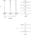
- the zoom lens ZL according to the first embodiment includes a first lens group G1 having negative refractive power and a second lens group having positive refractive power, which are arranged in order from the object side.
- G2 a third lens group G3 having a negative refractive power, and a fourth lens group G4 having a positive refractive power.
- the group G1 has a negative meniscus lens L11 having a convex surface on the object side closest to the object side, and at least a part of the first lens group G1 to the fourth lens group G4 has image stabilization for correcting image blur.
- the lens group is provided so as to be movable so as to have a component perpendicular to the optical axis, and the fourth lens group G4 includes at least four lenses.
- the zoom lens ZL of the first embodiment has a negative leading four-group configuration.
- a negative meniscus lens L11 having a convex surface facing the object side is disposed closest to the object side of the first lens group G1, thereby achieving good aberration correction (for example, distortion aberration, Field curvature).
- At least a part of the first lens group G1 to the fourth lens group G4 has a component in a direction perpendicular to the optical axis as a vibration-proof lens group for correcting image blur.
- the fourth lens group G4 by configuring the fourth lens group G4 with four or more lenses, an F-number can be secured, and good aberration correction (for example, spherical aberration, field curvature) ) Is possible.
- good aberration correction for example, spherical aberration, field curvature
- the zoom lens ZL according to the second embodiment includes a first lens group G1 having negative refractive power and a second lens group having positive refractive power arranged in order from the object side.
- G2 a third lens group G3 having a negative refractive power
- a fourth lens group G4 having a positive refractive power.
- the group G1 has a negative meniscus lens L11 on the most object side, and at least a part of the first lens group G1 to the fourth lens group G4 has an optical axis as an anti-vibration lens group for correcting image blur.
- the fourth lens group G4 is provided so as to be movable so as to have a vertical component, and is configured to include at least three lenses.
- At least a part of the first lens group G1 to the fourth lens group G4 has a component in a direction perpendicular to the optical axis as a vibration-proof lens group for correcting image blur.
- an F-number can be secured, and good aberration correction (for example, spherical aberration, image surface) Bend).
- the zoom lens ZL according to the first and second embodiments satisfies the following conditional expression (1).
- fw focal length of the entire system in the wide-angle end state
- f2 focal length of the second lens group G2.
- Conditional expression (1) is a relational expression between the focal length of the entire system in the wide-angle end state and the focal length with the second lens group G2, and obtains the optimum power of the second lens group G2. If the upper limit value of conditional expression (1) is exceeded, the power of the second lens group G2 becomes relatively strong, and the coma aberration is insufficiently corrected. If the lower limit of conditional expression (1) is not reached, the power of the second lens group G2 becomes relatively weak, the correction of spherical aberration is insufficient, and the lens system becomes enormous.
- the upper limit of conditional expression (1) In order to ensure the effect of each embodiment, it is preferable to set the upper limit of conditional expression (1) to 0.50. In order to further secure the effect of each embodiment, it is more preferable to set the upper limit of conditional expression (1) to 0.45. In order to maximize the effect of each embodiment, it is preferable to set the upper limit of conditional expression (1) to 0.40.
- the zoom lens ZL according to the first and second embodiments satisfies the following conditional expression (2).
- fw focal length of the entire system in the wide-angle end state
- ft focal length of the entire system in the telephoto end state
- Fw Open F value in the wide-angle end state.
- Conditional expression (2) is a relational expression between the zoom ratio and the F value in the wide-angle end state, and obtains the optimum specification of the zoom lens ZL according to the first and second embodiments. If the upper limit value of conditional expression (2) is exceeded, the F value becomes too bright and it becomes difficult to correct spherical aberration. In addition, it is difficult to ensure the zoom ratio. Here, if it is attempted to ensure the zoom ratio, correction of curvature of field and coma becomes particularly difficult. If the lower limit value of conditional expression (2) is not reached, the F value becomes dark and the zoom ratio becomes small, so it is not an attractive lens.
- the zoom lens ZL according to the first and second embodiments, at least a part of the third lens group G3 is provided as a vibration-proof lens group so as to be movable so as to have a component perpendicular to the optical axis. It is preferable.
- This configuration makes it possible to satisfactorily suppress coma fluctuations during image blur correction.
- the lens system can be reduced in size.
- the zoom lens ZL according to the first and second embodiments satisfies the following conditional expression (3).
- ft focal length of the entire system in the telephoto end state
- f2 focal length of the second lens group G2.
- Conditional expression (3) is a relational expression between the focal length of the entire system in the telephoto end state and the focal length of the second lens group G2, and obtains the optimum power of the second lens group G2. If the upper limit value of conditional expression (3) is exceeded, the power of the second lens group G2 becomes relatively strong, and the coma aberration becomes insufficiently corrected. If the lower limit value of conditional expression (3) is not reached, the power of the second lens group G2 becomes relatively weak, the correction of spherical aberration is insufficient, and the lens system becomes enormous.
- the zoom lens ZL according to the first and second embodiments satisfies the following conditional expression (4).
- f1 Focal length of the first lens group G1
- f2 focal length of the second lens group G2.
- Conditional expression (4) is a relational expression between the focal length of the first lens group G1 and the focal length of the second lens group G2, and obtains an optimum specification of the zoom lens ZL according to each embodiment.
- the upper limit value of conditional expression (4) is exceeded, the power of the first lens group G1 becomes relatively weak, and the optical performance in the wide-angle end state is deteriorated (particularly coma aberration and distortion aberration).
- the lower limit value of conditional expression (4) is not reached, the power of the first lens group G1 becomes relatively strong, and coma aberration and distortion aberration are insufficiently corrected.
- the zoom lens ZL according to the first and second embodiments satisfies the following conditional expression (5).
- f2 focal length of the second lens group G2
- f3 focal length of the third lens group G3.
- Conditional expression (5) is a relational expression between the focal length of the second lens group G2 and the focal length of the third lens group G3, and obtains an optimum specification of the zoom lens ZL according to each embodiment. If the upper limit value of conditional expression (5) is exceeded, the power of the second lens group G2 becomes relatively weak, and the spherical aberration and the curvature of field become insufficiently corrected. If the lower limit value of conditional expression (5) is not reached, the power of the second lens group G2 becomes relatively strong, and the spherical aberration and the curvature of field become insufficiently corrected.
- the third lens group G3 includes a cemented lens of a positive lens and a negative lens.
- the first lens group G1 preferably includes a negative meniscus lens, a negative lens, and a positive lens arranged in order from the object side.
- This configuration can satisfactorily correct various aberrations such as distortion and curvature of field.
- the first lens group G1 has at least one aspheric lens.
- the most object side lens of the first lens group G1 is preferably an aspheric lens.
- This configuration provides a higher resolution image.
- the zoom lens ZL according to the first and second embodiments is configured to focus by moving at least a part of the second lens group G2 along the optical axis direction.
- This configuration can suppress fluctuations in field curvature during focusing. In addition, a good image can be obtained even in close-up shooting.
- the zoom lens ZL according to the first and second embodiments preferably has an aperture stop S between the second lens group G2 and the third lens group G3.
- This configuration can satisfactorily correct spherical aberration.
- the aperture stop S moves integrally with the third lens group G3 during zooming.
- This configuration can satisfactorily correct spherical aberration that occurs during zooming.
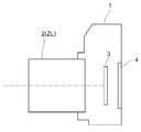
- the camera (imaging device) 1 including the above-described zoom lens ZL will be described with reference to FIG.
- the camera 1 is an interchangeable lens camera (so-called mirrorless camera) provided with the zoom lens ZL described above as the photographing lens 2.
- the camera 1 In the camera 1, light from an object (subject) (not shown) is collected by the photographing lens 2, and the subject is placed on the imaging surface of the imaging unit 3 via an OLPF (Optical Low Pass Filter) (not shown). Form an image. Then, the subject image is photoelectrically converted by the photoelectric conversion element provided in the imaging unit 3 to generate an image of the subject. This image is displayed on an EVF (Electronic view finder) 4 provided in the camera 1. Thus, the photographer can observe the subject via the EVF 4.
- EVF Electronic view finder
- a release button (not shown) is pressed by the photographer, an image of the subject generated by the imaging unit 3 is stored in a memory (not shown). In this way, the photographer can shoot the subject with the camera 1.
- the zoom lens ZL mounted on the camera 1 as the photographic lens 2 is a bright zoom lens having an anti-vibration function, a bright and high imaging performance due to its characteristic lens configuration, as can be seen from each example described later. Realized.
- the camera 1 can be provided with an image pickup apparatus having a vibration-proof function, a bright and high imaging performance.
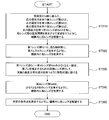
- a method of manufacturing the zoom lens ZL according to the first embodiment will be outlined with reference to FIG.
- the fourth lens group G4 having a positive refractive power, and each lens is arranged so as to perform zooming by changing the air interval of each lens group (step ST110).
- the first lens group G1 has a negative meniscus lens having a convex surface facing the object side closest to the object side (step ST120).
- At least a part of the first lens group G1 to the fourth lens group G4 is provided as a vibration-proof lens group for correcting image blur so as to be movable so as to have a component perpendicular to the optical axis (step ST130).
- the fourth lens group G4 has at least four lenses (step ST140). Among the conditional expressions, the lenses are arranged so as to satisfy at least conditional expression (1) (step ST150).
- the fourth lens group G4 having a positive refractive power, and each lens is arranged so as to perform zooming by changing the air interval of each lens group (step ST210).
- the first lens group G1 has a negative meniscus lens closest to the object side (step ST220).
- At least a part of the first lens group G1 to the fourth lens group G4 is provided as a vibration-proof lens group for correcting image blur so as to be movable so as to have a component perpendicular to the optical axis (step ST230).
- the fourth lens group G4 has at least three lenses (step ST240). Among the conditional expressions, the lenses are arranged so as to satisfy at least conditional expression (2) (step ST250).
- a negative meniscus lens L11 having a convex surface facing the object side
- a biconcave lens L12 having a convex surface on the object side.
- An oriented positive meniscus lens L13 is disposed.
- a positive meniscus lens L21 having a convex surface directed toward the object side
- a biconvex lens L22 in order from the object side, a positive meniscus lens L21 having a convex surface directed toward the object side, a biconvex lens L22, and a cemented lens of a biconvex lens L23 and a biconcave lens L24 are arranged.
- a cemented lens of a positive meniscus lens L31 having a convex surface directed toward the image side and a biconcave lens L32 is disposed in order from the object side.
- a biconvex lens L41, a cemented lens of a negative meniscus lens L42 having a concave surface directed to the image side, and a biconvex lens L43, and a cemented lens of a biconvex lens L44 and a biconcave lens L45 Place.
- the third lens group G3 is provided as a vibration-proof lens group for correcting image blur so as to be movable so as to have a component perpendicular to the optical axis. Further, each lens is arranged so as to satisfy a predetermined conditional expression.
- Tables 1 to 3 are shown below. These are tables of specifications in the first to third examples.
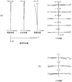
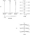
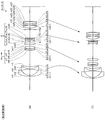
- FIG. 6 and FIG. 11 are cross-sectional views showing the configuration of a variable magnification optical system ZL (ZL1 to ZL3) according to each example.
- ZL1 to ZL3 the movement trajectory along the optical axis of each of the lens groups G1 to G4 when changing magnification from the wide-angle end state (W) to the telephoto end state (T) is indicated by an arrow. .
- d-line (wavelength 587.5620 nm) and g-line (wavelength 435.8350 nm) are selected as the calculation targets of the aberration characteristics.
- the surface number is the order of the optical surfaces from the object side along the traveling direction of the light beam
- r is the radius of curvature of each optical surface
- D is the next optical surface from each optical surface (or The distance between the surfaces on the optical axis to the image plane)
- ⁇ d is the Abbe number based on the d-line of the material of the optical member
- nd is the refractive index of the material of the optical member with respect to the d-line.
- (Variable) is a variable surface interval
- “ ⁇ ” of the radius of curvature is a plane or aperture
- (Aperture S) is an aperture aperture S
- (Aperture FS) is a flare-cut aperture FS
- Bf is a back focus (lens on the optical axis) The distance from the final plane to the image plane I).
- the refractive index of air (d-line) “1.00000” is omitted.
- the optical surface is an aspherical surface
- “*” is attached to the left side of the surface number, and the paraxial radius of curvature is indicated in the column of the radius of curvature R.
- f is the focal length of the entire lens system
- FNO is the F number
- 2 ⁇ is the angle of view (unit: °)
- Y is the image height
- TL is the total length of the lens system (on the optical axis)
- Bf represents the back focus (distance from the last lens surface to the image plane I on the optical axis).
- f is the focal length of the entire lens system
- R is the shooting distance
- D0 is the distance from the object surface to the first surface
- Di (where i is an integer) is the i-th surface and the first surface.
- the variable interval on the (i + 1) plane, Bf indicates the back focus.
- the first surface of each group shows the start surface number (most object side surface number), and the group focal length shows the focal length of each group.
- mm is generally used for the focal length f, the radius of curvature r, the surface interval D, and other lengths, etc. unless otherwise specified, but the optical system is proportionally enlarged. Alternatively, the same optical performance can be obtained even by proportional reduction, and the present invention is not limited to this. Further, the unit is not limited to “mm”, and other appropriate units can be used.
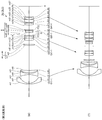
- the zoom lens ZL (ZL1) includes a first lens group G1 having negative refractive power arranged in order from the object side along the optical axis, and positive refractive power.
- the first lens group G1 is composed of a negative meniscus lens L11 having a convex surface facing the object side, a biconcave lens L12, and a positive meniscus lens L13 having a convex surface facing the object side, which are arranged in order from the object side.
- the image side surface of the negative meniscus lens L11 is aspheric.
- the second lens group G2 is composed of a positive meniscus lens L21 having a convex surface directed toward the object side, a biconvex lens L22, and a cemented lens of a biconvex lens L23 and a biconcave lens L24 arranged in order from the object side.
- the object side surface of the positive meniscus lens L21 is aspheric.
- the image side surface of the biconcave lens L24 is aspheric.
- the third lens group G3 is composed of a cemented lens composed of a positive meniscus lens L31 and a biconcave lens L32 arranged in order from the object side and having a convex surface directed toward the image side.
- the image side surface of the biconcave lens L32 is aspheric.
- the fourth lens group G4 includes a biconvex lens L41 arranged in order from the object side, a cemented lens of a negative meniscus lens L42 having a concave surface directed toward the image side, and a biconvex lens L43, and a cemented lens of the biconvex lens L44 and the biconcave lens L45. It consists of a lens.
- the object side surface of the biconvex lens L44 is aspheric.
- the first flare cut stop FS1 is provided on the most image side of the second lens group G2.
- An aperture stop S is provided (on the image side of the stop FS1) and between the second lens group G2 and the third lens group G3.
- a second flare cut stop FS2 is provided on the most image side of the third lens group G3.
- the image plane I is formed on an image sensor (not shown), and the image sensor is composed of a CCD, a CMOS, or the like.
- the zoom lens ZL1 has an air gap between the first lens group G1 and the second lens group G2, an air gap between the second lens group G2 and the third lens group G3, and a third lens group during zooming.
- the first lens group G1 to the fourth lens group G4 move along the optical axis so that the air distance between the air gap between G3 and the fourth lens group G4 changes.
- the first lens group G1 moves to the image side along the optical axis so as to draw a convex locus on the image side.
- the second lens group G2 to the fourth lens group G4 move toward the object side along the optical axis.
- the aperture stop S moves together with the third lens group G3 toward the object side along the optical axis.
- Focusing is performed by moving the positive meniscus lens L21 constituting the second lens group G2 along the optical axis (as the focusing group). Specifically, when focusing from an object at infinity to an object at a short distance, the positive meniscus lens L21 is moved to the image side along the optical axis.
- image blur correction on the image plane I is performed by moving the entire third lens group G3 as a vibration-proof lens group so as to have a component perpendicular to the optical axis.
- Table 1 below shows the values of each item in the first example.
- Surface numbers 1 to 27 in Table 1 correspond to the optical surfaces m1 to m27 shown in FIG.
- Conditional expression (2): (ft / fw) /Fw 1.69
- Conditional expression (3): ft / f2 1.02
- Conditional expression (4): ( ⁇ f1) /f2 0.716
- Conditional expression (5): f2 / ( ⁇ f3) 0.965
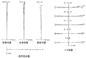
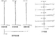
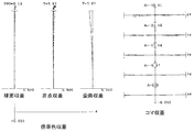
- FIG. 2A is a diagram illustrating various aberrations when focusing on infinity
- FIG. 2B is focusing on infinity.
- FIG. 5A is a diagram illustrating various aberrations when focusing on infinity
- FIG. 5B is focusing on infinity.
- FNO is the F number
- Y is the image height
- A is the half angle of view (unit: °)
- d is the aberration at the d-line
- g is the aberration at the g-line.
- Those without d and g indicate aberration at the d-line.
- the F-number value corresponding to the maximum aperture is shown
- the astigmatism diagram and the distortion diagram the maximum image height is shown.
- the solid line indicates the sagittal image plane
- the broken line indicates the meridional image plane.
- a solid line indicates a meridional coma
- a broken line indicates a sagittal coma.
- the zoom lens ZL1 according to the first example has a high imaging performance with various aberrations corrected well from the wide-angle end state to the telephoto end state. It can also be seen that the image forming performance is high even when image blur correction is performed.
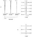
- the zoom lens ZL (ZL2) includes a first lens group G1 having negative refractive power arranged in order from the object side along the optical axis, and positive refractive power.
- the first lens group G1 is composed of a negative meniscus lens L11 having a convex surface facing the object side and a cemented lens of a biconcave lens L12 and a positive meniscus lens L13 having a convex surface facing the object side, which are arranged in order from the object side.
- the image side surface of the negative meniscus lens L11 is aspheric.
- the second lens group G2 includes, in order from the object side, a positive meniscus lens L21 having a convex surface facing the object side, a cemented lens of a negative meniscus lens L22 having a concave surface facing the image side and a biconvex lens L23, and a biconvex lens. L24.
- the object side surface of the positive meniscus lens L21 is aspheric.
- the object side surface of the biconvex lens L24 is aspheric.
- the third lens group G3 includes a cemented lens of a biconvex lens L31 and a biconcave lens L32, and a biconcave lens L33, which are arranged in order from the object side.
- the fourth lens group G4 is formed by joining a biconvex lens L41, a positive meniscus lens L42 having a convex surface toward the image side, and a negative meniscus lens L44 having a concave surface toward the object side, which are arranged in order from the object side. It consists of a lens.
- the object side surface of the negative meniscus lens L44 is aspheric.
- An aperture stop S is provided between the second lens group G2 and the third lens group G3.
- a first flare cut stop FS1 is provided on the most image side of the third lens group G3.
- a second flare cut stop FS2 is provided on the most object side of the fourth lens group G4.
- the image plane I is formed on an image sensor (not shown), and the image sensor is composed of a CCD, a CMOS, or the like.
- the zoom lens ZL2 has an air gap between the first lens group G1 and the second lens group G2, an air gap between the second lens group G2 and the third lens group G3, and a third lens group during zooming.
- the first lens group G1 to the fourth lens group G4 move along the optical axis so that the air distance between the air gap between G3 and the fourth lens group G4 changes.
- the first lens group G1 moves toward the object side along the optical axis so as to draw a convex locus on the image side.
- the second lens group G2 to the fourth lens group G4 move toward the object side along the optical axis.
- the aperture stop S moves together with the third lens group G3 toward the object side along the optical axis.
- Focusing is performed by a positive meniscus lens L21 having a convex surface facing the object side, a negative meniscus lens L22 having a concave surface facing the image side, and a biconvex lens L23, which are arranged in order from the object side.
- This is performed by moving a lens group composed of a cemented lens along the optical axis as a focusing group. Specifically, when focusing from an object at infinity to a near object, the focusing group is moved to the image side along the optical axis.
- image blur correction on the image plane I is performed by moving the entire third lens group G3 as a vibration-proof lens group so as to have a component perpendicular to the optical axis.
- Table 2 below shows the values of each item in the second example.
- Surface numbers 1 to 27 in Table 2 correspond to the optical surfaces m1 to m27 shown in FIG.
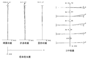
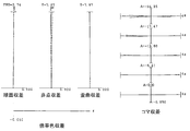
- FIG. 7A is a diagram illustrating various aberrations when focusing on infinity
- FIG. 7B is focusing on infinity.
- the zoom lens ZL2 according to the second example has a high imaging performance with various aberrations corrected well from the wide-angle end state to the telephoto end state. It can also be seen that the image forming performance is high even when image blur correction is performed.
- the zoom lens ZL (ZL3) according to the third example includes a first lens group G1 having negative refractive power arranged in order from the object side along the optical axis, and positive refractive power.
- the first lens group G1 is composed of a negative meniscus lens L11 having a convex surface facing the object side, a biconcave lens L12, and a positive meniscus lens L13 having a convex surface facing the object side, which are arranged in order from the object side.
- the image side surface of the negative meniscus lens L11 is aspheric.
- the second lens group G2 includes a positive meniscus lens L21 having a convex surface facing the object side, a biconvex lens L22, a biconvex lens L23, and a negative meniscus lens L24 having a concave surface facing the object side, which are arranged in order from the object side. .
- the object side surface of the positive meniscus lens L21 is aspheric.
- the image side surface of the negative meniscus lens L24 is aspheric.
- the third lens group G3 is composed of a positive meniscus lens L31 and a biconcave lens L32 arranged in order from the object side and having a convex surface directed toward the image side.
- the image side surface of the biconcave lens L32 is aspheric.
- the fourth lens group G4 includes a biconvex lens L41 arranged in order from the object side, a cemented lens of a negative meniscus lens L42 having a concave surface directed toward the image side, and a biconvex lens L43, and a cemented lens of the biconvex lens L44 and the biconcave lens L45. It consists of a lens.
- the object side surface of the biconvex lens L44 is aspheric.
- the first flare cut stop FS1 is provided on the most image side of the second lens group G2.
- An aperture stop S is provided (on the image side of the stop FS1) and between the second lens group G2 and the third lens group G3.
- a second flare cut stop FS2 is provided on the most image side of the third lens group G3.
- the image plane I is formed on an image sensor (not shown), and the image sensor is composed of a CCD, a CMOS, or the like.
- the zoom lens ZL3 has an air gap between the first lens group G1 and the second lens group G2, an air gap between the second lens group G2 and the third lens group G3, and a third lens group during zooming.
- the first lens group G1 to the fourth lens group G4 move along the optical axis so that the air distance between the air gap between G3 and the fourth lens group G4 changes.
- the first lens group G1 moves to the image side along the optical axis so as to draw a convex locus on the image side.
- the second lens group G2 to the fourth lens group G4 move toward the object side along the optical axis.
- the aperture stop S moves together with the third lens group G3 toward the object side along the optical axis.
- Focusing is performed by moving the positive meniscus lens L21 constituting the second lens group G2 along the optical axis (as the focusing group). Specifically, when focusing from an object at infinity to an object at a short distance, the positive meniscus lens L21 is moved to the image side along the optical axis.
- image blur correction on the image plane I is performed by moving the entire third lens group G3 as a vibration-proof lens group so as to have a component perpendicular to the optical axis.
- Table 3 shows the values of each item in the third example.
- Surface numbers 1 to 27 in Table 3 correspond to the optical surfaces m1 to m27 shown in FIG.
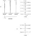
- FIG. 15A is a diagram illustrating various aberrations at the time of focusing on infinity
- the zoom lens ZL3 according to the third example has a high imaging performance with various aberrations corrected well from the wide-angle end state to the telephoto end state. It can also be seen that the image forming performance is high even when image blur correction is performed.
- Each of the above examples shows a specific example of the zoom lens according to the first and second embodiments, and the zoom lens according to the first and second embodiments is not limited thereto. It is not something.
- the following contents can be appropriately adopted as long as the optical performance is not impaired.
- the four-group configuration is shown, but the present invention can also be applied to other group configurations such as five groups.
- a configuration in which a lens or a lens group is added closest to the object side, or a configuration in which a lens or a lens group is added closest to the image side may be used.
- the lens group refers to a portion having at least one lens separated by an air interval that changes at the time of zooming or focusing.
- a single lens group, a plurality of lens groups, or a partial lens group may be moved in the optical axis direction to be a focusing lens group that performs focusing from an object at infinity to a near object.
- This focusing lens group can be applied to autofocus, and is also suitable for driving a motor for autofocus (using an ultrasonic motor or the like).
- the lens group or the partial lens group is moved so as to have a component in a direction perpendicular to the optical axis, or is rotated (oscillated) in the in-plane direction including the optical axis.
- a vibration-proof lens group that corrects image blur caused by camera shake may be used.
- the lens surface may be formed of a spherical surface, a flat surface, or an aspheric surface.
- the lens surface is a spherical surface or a flat surface, lens processing and assembly adjustment are facilitated, and optical performance deterioration due to errors in processing and assembly adjustment can be prevented.
- the lens surface is aspherical, the aspherical surface is an aspherical surface by grinding, a glass mold aspherical surface that is formed of glass with an aspherical shape, or a composite type nonspherical surface that is formed of a resin on the surface of glass. Any aspherical surface may be used.
- the lens surface may be a diffractive surface, and the lens may be a gradient index lens (GRIN lens) or a plastic lens.
- GRIN lens gradient index lens
- the aperture stop is preferably disposed in the vicinity of the third lens group G3.
- the flare-cut stop is preferably arranged in the vicinity of the second lens group G2 and the third lens group G3, but the role may be substituted by a lens frame without providing a member.
- each lens surface is provided with an antireflection film having a high transmittance in a wide wavelength range in order to reduce flare and ghost and achieve high contrast and high optical performance. Also good.
- the zoom lens ZL of the first and second embodiments has a zoom ratio of about 3 times, but is suitable for a zoom lens of about 2 to 7.
Abstract
The present invention includes, in order from the object side, a first lens group (G1) having a negative refractive power, a second lens group (G2) having a positive refractive power, a third lens group (G3) having a negative refractive power, and a fourth lens group (G4) having a positive refractive power. The air gap between each lens group is varied to vary the magnification. The first lens group (G1) includes, on the furthermost object side, a negative meniscus lens (L11) having a surface that protrudes towards the object side. At least part of the first lens group (G1) to the fourth lens group (G4) acts as a vibration-proof lens group for correcting image blur and is moveable so as to have a component in the direction perpendicular to the optical axis. The fourth lens group (G4) includes at least four lenses, and satisfies conditional formula (1) (0.20<fw/f2<0.55), in which fw is the focal distance of the entire system in a wide angle end state, and f2 is the focal distance of the second lens group (G2).
Description
本発明は、ズームレンズ、撮像装置及びズームレンズの製造方法に関する。
The present invention relates to a zoom lens, an imaging apparatus, and a method for manufacturing a zoom lens.
従来、負先行型の4群ズームレンズは多数提案されているが、明るく、防振機能を備えたものは少なかった(例えば、特許文献1、2参照)。
Conventionally, many negative leading type four-group zoom lenses have been proposed, but few were bright and provided with an anti-vibration function (for example, see Patent Documents 1 and 2).
近年のデジタル化に伴い、防振機能を備えつつ、より明るく、よりレンズ性能の高いズームレンズが求められている。
With the recent digitalization, there is a need for a zoom lens that has an anti-vibration function and is brighter and has higher lens performance.
第1の発明に係るズームレンズは、物体側から順に並んだ、負の屈折力を有する第1レンズ群と、正の屈折力を有する第2レンズ群と、負の屈折力を有する第3レンズ群と、正の屈折力を有する第4レンズ群とを有し、各レンズ群の空気間隔を変化させて変倍を行い、前記第1レンズ群は、最も物体側に、物体側に凸面を向けた負メニスカスレンズを有し、前記第1レンズ群~前記第4レンズ群の少なくとも一部は、像ブレを補正するための防振レンズ群として、光軸と垂直方向の成分を持つように移動可能に設けられ、前記第4レンズ群は、少なくとも4枚のレンズを有し、次の条件式を満足する。
A zoom lens according to a first aspect of the present invention includes a first lens group having negative refractive power, a second lens group having positive refractive power, and a third lens having negative refractive power, which are arranged in order from the object side. And a fourth lens group having a positive refractive power, and performing zooming by changing the air interval of each lens group, the first lens group having a convex surface closest to the object side and the object side. A negative meniscus lens directed at least, and at least a part of the first lens group to the fourth lens group has a component in a direction perpendicular to the optical axis as a vibration-proof lens group for correcting image blur The fourth lens group includes at least four lenses, and satisfies the following conditional expression.
0.20 < fw/f2 < 0.55
但し、
fw:広角端状態における全系の焦点距離、
f2:前記第2レンズ群の焦点距離。 0.20 <fw / f2 <0.55
However,
fw: focal length of the entire system in the wide-angle end state,
f2: focal length of the second lens group.
但し、
fw:広角端状態における全系の焦点距離、
f2:前記第2レンズ群の焦点距離。 0.20 <fw / f2 <0.55
However,
fw: focal length of the entire system in the wide-angle end state,
f2: focal length of the second lens group.
第1の発明に係る撮像装置は、上記第1の発明に係る変倍光学系を備える。
An imaging apparatus according to a first invention includes the variable magnification optical system according to the first invention.
第2の発明に係るズームレンズは、物体側から順に並んだ、負の屈折力を有する第1レンズ群と、正の屈折力を有する第2レンズ群と、負の屈折力を有する第3レンズ群と、正の屈折力を有する第4レンズ群とを有し、各レンズ群の空気間隔を変化させて変倍を行い、前記第1レンズ群は、最も物体側に、負メニスカスレンズを有し、前記第1レンズ群~前記第4レンズ群の少なくとも一部は、像ブレを補正するための防振レンズ群として、光軸と垂直方向の成分を持つように移動可能に設けられ、前記第4レンズ群は、少なくとも3枚のレンズを有し、次の条件式を満足する。
A zoom lens according to a second aspect of the present invention includes a first lens group having negative refractive power, a second lens group having positive refractive power, and a third lens having negative refractive power, which are arranged in order from the object side. And a fourth lens group having a positive refractive power. The first lens group has a negative meniscus lens closest to the object side by changing the air interval of each lens group. At least a part of the first lens group to the fourth lens group is provided as a vibration-proof lens group for correcting image blur so as to be movable so as to have a component perpendicular to the optical axis. The fourth lens group has at least three lenses and satisfies the following conditional expression.
1.00 < (ft/fw)/Fw < 2.00
但し、
fw:広角端状態における全系の焦点距離、
ft:望遠端状態における全系の焦点距離、
Fw:広角端状態における開放F値。 1.00 <(ft / fw) / Fw <2.00
However,
fw: focal length of the entire system in the wide-angle end state,
ft: focal length of the entire system in the telephoto end state,
Fw: Open F value in the wide-angle end state.
但し、
fw:広角端状態における全系の焦点距離、
ft:望遠端状態における全系の焦点距離、
Fw:広角端状態における開放F値。 1.00 <(ft / fw) / Fw <2.00
However,
fw: focal length of the entire system in the wide-angle end state,
ft: focal length of the entire system in the telephoto end state,
Fw: Open F value in the wide-angle end state.
第2の発明に係る撮像装置は、上記第2の発明に係る変倍光学系を備える。
An image pickup apparatus according to a second invention includes the variable magnification optical system according to the second invention.
第1の発明のズームレンズの製造方法は、物体側から順に並んだ、負の屈折力を有する第1レンズ群と、正の屈折力を有する第2レンズ群と、負の屈折力を有する第3レンズ群と、正の屈折力を有する第4レンズ群とを有するズームレンズの製造方法であって、各レンズ群の空気間隔を変化させて変倍を行い、前記第1レンズ群は、最も物体側に、物体側に凸面を向けた負メニスカスレンズを有し、前記第1レンズ群~前記第4レンズ群の少なくとも一部は、像ブレを補正するための防振レンズ群として、光軸と垂直方向の成分を持つように移動可能に設けられ、前記第4レンズ群は、少なくとも4枚のレンズを有し、次の条件式を満足するように、レンズ鏡筒内に各レンズを配置する。
The zoom lens manufacturing method according to the first aspect of the present invention includes a first lens group having a negative refractive power, a second lens group having a positive refractive power, and a first lens group having a negative refractive power, arranged in order from the object side. A zoom lens manufacturing method having three lens groups and a fourth lens group having a positive refractive power, and performing zooming by changing an air interval of each lens group. A negative meniscus lens having a convex surface facing the object side is provided on the object side, and at least a part of the first lens group to the fourth lens group serves as an anti-vibration lens group for correcting image blur as an optical axis. The fourth lens group has at least four lenses, and each lens is arranged in the lens barrel so that the following conditional expression is satisfied. To do.
0.20 < fw/f2 < 0.55
但し、
fw:広角端状態における全系の焦点距離、
f2:前記第2レンズ群の焦点距離。 0.20 <fw / f2 <0.55
However,
fw: focal length of the entire system in the wide-angle end state,
f2: focal length of the second lens group.
但し、
fw:広角端状態における全系の焦点距離、
f2:前記第2レンズ群の焦点距離。 0.20 <fw / f2 <0.55
However,
fw: focal length of the entire system in the wide-angle end state,
f2: focal length of the second lens group.
第2の発明のズームレンズの製造方法は、物体側から順に並んだ、負の屈折力を有する第1レンズ群と、正の屈折力を有する第2レンズ群と、負の屈折力を有する第3レンズ群と、正の屈折力を有する第4レンズ群とを有するズームレンズの製造方法であって、各レンズ群の空気間隔を変化させて変倍を行い、前記第1レンズ群は、最も物体側に、負メニスカスレンズを有し、前記第1レンズ群~前記第4レンズ群の少なくとも一部は、像ブレを補正するための防振レンズ群として、光軸と垂直方向の成分を持つように移動可能に設けられ、前記第4レンズ群は、少なくとも3枚のレンズを有し、次の条件式を満足するように、レンズ鏡筒内に各レンズを配置する。
The zoom lens manufacturing method according to the second aspect of the present invention includes a first lens group having a negative refractive power, a second lens group having a positive refractive power, and a first lens group having a negative refractive power, arranged in order from the object side. A zoom lens manufacturing method having three lens groups and a fourth lens group having a positive refractive power, and performing zooming by changing an air interval of each lens group. A negative meniscus lens is provided on the object side, and at least a part of the first to fourth lens groups has a component in a direction perpendicular to the optical axis as a vibration-proof lens group for correcting image blur. The fourth lens group has at least three lenses, and each lens is arranged in the lens barrel so as to satisfy the following conditional expression.
1.00 < (ft/fw)/Fw < 2.00
但し、
fw:広角端状態における全系の焦点距離、
ft:望遠端状態における全系の焦点距離、
Fw:広角端状態における開放F値。 1.00 <(ft / fw) / Fw <2.00
However,
fw: focal length of the entire system in the wide-angle end state,
ft: focal length of the entire system in the telephoto end state,
Fw: Open F value in the wide-angle end state.
但し、
fw:広角端状態における全系の焦点距離、
ft:望遠端状態における全系の焦点距離、
Fw:広角端状態における開放F値。 1.00 <(ft / fw) / Fw <2.00
However,
fw: focal length of the entire system in the wide-angle end state,
ft: focal length of the entire system in the telephoto end state,
Fw: Open F value in the wide-angle end state.
以下、第1および第2の実施形態について、図面を参照しながら説明する。
Hereinafter, the first and second embodiments will be described with reference to the drawings.
第1の実施形態に係るズームレンズZLは、例えば図1に示すように、物体側から順に並んだ、負の屈折力を有する第1レンズ群G1と、正の屈折力を有する第2レンズ群G2と、負の屈折力を有する第3レンズ群G3と、正の屈折力を有する第4レンズ群G4とを有し、各レンズ群の空気間隔を変化させて変倍を行い、第1レンズ群G1は、最も物体側に、物体側に凸面を向けた負メニスカスレンズL11を有し、第1レンズ群G1~第4レンズ群G4の少なくとも一部は、像ブレを補正するための防振レンズ群として、光軸と垂直方向の成分を持つように移動可能に設けられ、第4レンズ群G4は、少なくとも4枚のレンズを有して構成される。
As shown in FIG. 1, for example, the zoom lens ZL according to the first embodiment includes a first lens group G1 having negative refractive power and a second lens group having positive refractive power, which are arranged in order from the object side. G2, a third lens group G3 having a negative refractive power, and a fourth lens group G4 having a positive refractive power. The group G1 has a negative meniscus lens L11 having a convex surface on the object side closest to the object side, and at least a part of the first lens group G1 to the fourth lens group G4 has image stabilization for correcting image blur. The lens group is provided so as to be movable so as to have a component perpendicular to the optical axis, and the fourth lens group G4 includes at least four lenses.
第1の実施形態のズームレンズZLは、負先行型の4群構成である。このようなズームレンズZLにおいて、第1レンズ群G1の最も物体側に、物体側に凸面を向けた負メニスカスレンズL11を配置することにより、広角端状態において良好な収差補正(例えば、歪曲収差、像面湾曲)が可能となる。
The zoom lens ZL of the first embodiment has a negative leading four-group configuration. In such a zoom lens ZL, a negative meniscus lens L11 having a convex surface facing the object side is disposed closest to the object side of the first lens group G1, thereby achieving good aberration correction (for example, distortion aberration, Field curvature).
第1の実施形態のズームレンズZLは、第1レンズ群G1~第4レンズ群G4の少なくとも一部を、像ブレを補正するための防振レンズ群として、光軸と垂直方向の成分を持つように移動可能に設けることにより、防振性能と光学性能の両方を良好に確保することができる。
In the zoom lens ZL of the first embodiment, at least a part of the first lens group G1 to the fourth lens group G4 has a component in a direction perpendicular to the optical axis as a vibration-proof lens group for correcting image blur. Thus, by providing it so that it can move, both a vibration proof performance and optical performance can be ensured favorable.
第1の実施形態のズームレンズZLは、第4レンズ群G4を4枚以上のレンズで構成することにより、F値を確保することができ、良好な収差補正(例えば、球面収差、像面湾曲)が可能となる。
In the zoom lens ZL of the first embodiment, by configuring the fourth lens group G4 with four or more lenses, an F-number can be secured, and good aberration correction (for example, spherical aberration, field curvature) ) Is possible.
第2の実施形態に係るズームレンズZLは、例えば図1に示すように、物体側から順に並んだ、負の屈折力を有する第1レンズ群G1と、正の屈折力を有する第2レンズ群G2と、負の屈折力を有する第3レンズ群G3と、正の屈折力を有する第4レンズ群G4とを有し、各レンズ群の空気間隔を変化させて変倍を行い、第1レンズ群G1は、最も物体側に、負メニスカスレンズL11を有し、第1レンズ群G1~第4レンズ群G4の少なくとも一部は、像ブレを補正するための防振レンズ群として、光軸と垂直方向の成分を持つように移動可能に設けられ、第4レンズ群G4は、少なくとも3枚のレンズを有して構成される。
For example, as shown in FIG. 1, the zoom lens ZL according to the second embodiment includes a first lens group G1 having negative refractive power and a second lens group having positive refractive power arranged in order from the object side. G2, a third lens group G3 having a negative refractive power, and a fourth lens group G4 having a positive refractive power. The group G1 has a negative meniscus lens L11 on the most object side, and at least a part of the first lens group G1 to the fourth lens group G4 has an optical axis as an anti-vibration lens group for correcting image blur. The fourth lens group G4 is provided so as to be movable so as to have a vertical component, and is configured to include at least three lenses.
このように負先行型の4群構成のズームレンズにおいて、第1レンズ群G1の最も物体側に、物体側に凸面を向けた負メニスカスレンズL11を配置することにより、広角端状態において良好な収差補正(例えば、歪曲収差、像面湾曲)が可能となる。
In this way, in the negative leading type four-group zoom lens, by disposing the negative meniscus lens L11 having a convex surface on the object side closest to the object side of the first lens group G1, good aberration is obtained in the wide-angle end state. Correction (for example, distortion aberration, curvature of field) becomes possible.
第2の実施形態のズームレンズZLは、第1レンズ群G1~第4レンズ群G4の少なくとも一部を、像ブレを補正するための防振レンズ群として、光軸と垂直方向の成分を持つように移動可能に設けることにより、防振性能と光学性能の両方を良好に確保することができる。
In the zoom lens ZL of the second embodiment, at least a part of the first lens group G1 to the fourth lens group G4 has a component in a direction perpendicular to the optical axis as a vibration-proof lens group for correcting image blur. Thus, by providing it so that it can move, both a vibration proof performance and optical performance can be ensured favorable.
第2の実施形態のズームレンズZLは、第4レンズ群G4を少なくとも3枚以上のレンズで構成することにより、F値を確保することができ、良好な収差補正(例えば、球面収差、像面湾曲)が可能となる。
In the zoom lens ZL of the second embodiment, by configuring the fourth lens group G4 with at least three or more lenses, an F-number can be secured, and good aberration correction (for example, spherical aberration, image surface) Bend).
第1および第2の実施形態に係るズームレンズZLは、次の条件式(1)を満足する。
The zoom lens ZL according to the first and second embodiments satisfies the following conditional expression (1).
0.20 < fw/f2 < 0.55 …(1)
但し、
fw:広角端状態における全系の焦点距離、
f2:第2レンズ群G2の焦点距離。 0.20 <fw / f2 <0.55 (1)
However,
fw: focal length of the entire system in the wide-angle end state,
f2: focal length of the second lens group G2.
但し、
fw:広角端状態における全系の焦点距離、
f2:第2レンズ群G2の焦点距離。 0.20 <fw / f2 <0.55 (1)
However,
fw: focal length of the entire system in the wide-angle end state,
f2: focal length of the second lens group G2.
条件式(1)は、広角端状態における全系の焦点距離と、第2レンズ群G2との焦点距離との関係式であり、第2レンズ群G2の最適なパワーを求めるものである。条件式(1)の上限値を上回ると、相対的に第2レンズ群G2のパワーが強くなり過ぎ、コマ収差が補正不足となる。条件式(1)の下限値を下回ると、相対的に第2レンズ群G2のパワーが弱くなり過ぎ、球面収差の補正不足と、レンズ系が巨大化する。
Conditional expression (1) is a relational expression between the focal length of the entire system in the wide-angle end state and the focal length with the second lens group G2, and obtains the optimum power of the second lens group G2. If the upper limit value of conditional expression (1) is exceeded, the power of the second lens group G2 becomes relatively strong, and the coma aberration is insufficiently corrected. If the lower limit of conditional expression (1) is not reached, the power of the second lens group G2 becomes relatively weak, the correction of spherical aberration is insufficient, and the lens system becomes enormous.
各実施形態の効果をより確実にするために、条件式(1)の上限値を0.50とすることが好ましい。各実施形態の効果をさらに確実にするために、条件式(1)の上限値を0.45とすることがより好ましい。各実施形態の効果を最大限に発揮するために、条件式(1)の上限値を0.40とすることが好ましい。
In order to ensure the effect of each embodiment, it is preferable to set the upper limit of conditional expression (1) to 0.50. In order to further secure the effect of each embodiment, it is more preferable to set the upper limit of conditional expression (1) to 0.45. In order to maximize the effect of each embodiment, it is preferable to set the upper limit of conditional expression (1) to 0.40.
各実施形態の効果をより確実にするために、条件式(1)の下限値を0.25とすることが好ましい。各実施形態の効果を最大限に発揮するために、条件式(1)の下限値を0.30とすることが好ましい。
In order to secure the effect of each embodiment, it is preferable to set the lower limit of conditional expression (1) to 0.25. In order to maximize the effect of each embodiment, it is preferable to set the lower limit of conditional expression (1) to 0.30.
第1および第2の実施形態に係るズームレンズZLは、次の条件式(2)を満足する。
The zoom lens ZL according to the first and second embodiments satisfies the following conditional expression (2).
1.00 < (ft/fw)/Fw < 2.00 …(2)
但し、
fw:広角端状態における全系の焦点距離、
ft:望遠端状態における全系の焦点距離、
Fw:広角端状態における開放F値。 1.00 <(ft / fw) / Fw <2.00 (2)
However,
fw: focal length of the entire system in the wide-angle end state,
ft: focal length of the entire system in the telephoto end state,
Fw: Open F value in the wide-angle end state.
但し、
fw:広角端状態における全系の焦点距離、
ft:望遠端状態における全系の焦点距離、
Fw:広角端状態における開放F値。 1.00 <(ft / fw) / Fw <2.00 (2)
However,
fw: focal length of the entire system in the wide-angle end state,
ft: focal length of the entire system in the telephoto end state,
Fw: Open F value in the wide-angle end state.
条件式(2)は、ズーム比と、広角端状態におけるF値との関係式であり、第1および第2の実施形態に係るズームレンズZLの最適なスペックを求めるものである。条件式(2)の上限値を上回ると、F値が明るくなり過ぎ、球面収差の補正が困難となる。また、ズーム比の確保が困難となる。ここで、無理にズーム比を確保しようとすると、特に、像面湾曲、コマ収差の補正が困難になる。条件式(2)の下限値を下回ると、F値が暗くなったり、ズーム比が小さくなったりするため、魅力的なレンズではなくなる。
Conditional expression (2) is a relational expression between the zoom ratio and the F value in the wide-angle end state, and obtains the optimum specification of the zoom lens ZL according to the first and second embodiments. If the upper limit value of conditional expression (2) is exceeded, the F value becomes too bright and it becomes difficult to correct spherical aberration. In addition, it is difficult to ensure the zoom ratio. Here, if it is attempted to ensure the zoom ratio, correction of curvature of field and coma becomes particularly difficult. If the lower limit value of conditional expression (2) is not reached, the F value becomes dark and the zoom ratio becomes small, so it is not an attractive lens.
各実施形態の効果をより確実にするために、条件式(2)の上限値を1.90とすることが好ましい。各実施形態の効果を最大限に発揮するために、条件式(2)の上限値を1.80とすることが好ましい。
In order to ensure the effect of each embodiment, it is preferable to set the upper limit of conditional expression (2) to 1.90. In order to maximize the effect of each embodiment, it is preferable to set the upper limit of conditional expression (2) to 1.80.
各実施形態の効果を最大限に発揮するために、条件式(2)の下限値を1.10とすることが好ましい。
In order to maximize the effect of each embodiment, it is preferable to set the lower limit of conditional expression (2) to 1.10.
第1および第2の実施形態に係るズームレンズZLにおいて、第3レンズ群G3の少なくとも一部は、防振レンズ群として、光軸と垂直方向の成分を持つように移動可能に設けられていることが好ましい。
In the zoom lens ZL according to the first and second embodiments, at least a part of the third lens group G3 is provided as a vibration-proof lens group so as to be movable so as to have a component perpendicular to the optical axis. It is preferable.
この構成により、像ブレ補正時のコマ収差の変動を良好に抑えることができる。また、レンズ系の小型化を図ることができる。
This configuration makes it possible to satisfactorily suppress coma fluctuations during image blur correction. In addition, the lens system can be reduced in size.
第1および第2の実施形態に係るズームレンズZLは、次の条件式(3)を満足することが好ましい。
It is preferable that the zoom lens ZL according to the first and second embodiments satisfies the following conditional expression (3).
0.90 < ft/f2 < 1.50 …(3)
但し、
ft:望遠端状態における全系の焦点距離、
f2:第2レンズ群G2の焦点距離。 0.90 <ft / f2 <1.50 (3)
However,
ft: focal length of the entire system in the telephoto end state,
f2: focal length of the second lens group G2.
但し、
ft:望遠端状態における全系の焦点距離、
f2:第2レンズ群G2の焦点距離。 0.90 <ft / f2 <1.50 (3)
However,
ft: focal length of the entire system in the telephoto end state,
f2: focal length of the second lens group G2.
条件式(3)は、望遠端状態における全系の焦点距離と、第2レンズ群G2の焦点距離との関係式であり、第2レンズ群G2の最適なパワーを求めるものである。条件式(3)の上限値を上回ると、相対的に第2レンズ群G2のパワーが強くなり過ぎ、コマ収差が補正不足となる。条件式(3)の下限値を下回ると、相対的に第2レンズ群G2のパワーが弱くなり過ぎ、球面収差の補正不足と、レンズ系が巨大化する。
Conditional expression (3) is a relational expression between the focal length of the entire system in the telephoto end state and the focal length of the second lens group G2, and obtains the optimum power of the second lens group G2. If the upper limit value of conditional expression (3) is exceeded, the power of the second lens group G2 becomes relatively strong, and the coma aberration becomes insufficiently corrected. If the lower limit value of conditional expression (3) is not reached, the power of the second lens group G2 becomes relatively weak, the correction of spherical aberration is insufficient, and the lens system becomes enormous.
各実施形態の効果をより確実にするために、条件式(3)の上限値を1.40とすることが好ましい。各実施形態の効果を最大限に発揮するために、条件式(3)の上限値を1.30とすることが好ましい。
In order to secure the effect of each embodiment, it is preferable to set the upper limit of conditional expression (3) to 1.40. In order to maximize the effect of each embodiment, it is preferable to set the upper limit of conditional expression (3) to 1.30.
各実施形態の効果をより確実にするために、条件式(3)の下限値を0.95とすることが好ましい。各実施形態の効果を最大限に発揮するために、条件式(3)の下限値を1.00とすることが好ましい。
In order to secure the effect of each embodiment, it is preferable to set the lower limit of conditional expression (3) to 0.95. In order to maximize the effect of each embodiment, it is preferable to set the lower limit of conditional expression (3) to 1.00.
第1および第2の実施形態に係るズームレンズZLは、次の条件式(4)を満足することが好ましい。
It is preferable that the zoom lens ZL according to the first and second embodiments satisfies the following conditional expression (4).
0.50 <(-f1)/f2 < 0.80 …(4)
但し、
f1:第1レンズ群G1の焦点距離、
f2:第2レンズ群G2の焦点距離。 0.50 <(− f1) / f2 <0.80 (4)
However,
f1: Focal length of the first lens group G1
f2: focal length of the second lens group G2.
但し、
f1:第1レンズ群G1の焦点距離、
f2:第2レンズ群G2の焦点距離。 0.50 <(− f1) / f2 <0.80 (4)
However,
f1: Focal length of the first lens group G1
f2: focal length of the second lens group G2.
条件式(4)は、第1レンズ群G1の焦点距離と、第2レンズ群G2の焦点距離との関係式であり、各実施形態に係るズームレンズZLの最適なスペックを求めるものである。条件式(4)の上限値を上回ると、相対的に第1レンズ群G1のパワーが弱くなり、広角端状態における光学性能が劣化する(特に、コマ収差、歪曲収差)。条件式(4)の下限値を下回ると、相対的に第1レンズ群G1のパワーが強くなり、コマ収差、歪曲収差が補正不足となる。
Conditional expression (4) is a relational expression between the focal length of the first lens group G1 and the focal length of the second lens group G2, and obtains an optimum specification of the zoom lens ZL according to each embodiment. When the upper limit value of conditional expression (4) is exceeded, the power of the first lens group G1 becomes relatively weak, and the optical performance in the wide-angle end state is deteriorated (particularly coma aberration and distortion aberration). If the lower limit value of conditional expression (4) is not reached, the power of the first lens group G1 becomes relatively strong, and coma aberration and distortion aberration are insufficiently corrected.
各実施形態の効果をより確実にするために、条件式(4)の上限値を0.75とすることが好ましい。各実施形態の効果を最大限に発揮するために、条件式(4)の上限値を0.70とすることが好ましい。
In order to secure the effect of each embodiment, it is preferable to set the upper limit of conditional expression (4) to 0.75. In order to maximize the effect of each embodiment, it is preferable to set the upper limit of conditional expression (4) to 0.70.
各実施形態の効果をより確実にするために、条件式(4)の下限値を0.55とすることが好ましい。各実施形態の効果を最大限に発揮するために、条件式(4)の下限値を0.60とすることが好ましい。
In order to secure the effect of each embodiment, it is preferable to set the lower limit of conditional expression (4) to 0.55. In order to maximize the effect of each embodiment, it is preferable to set the lower limit of conditional expression (4) to 0.60.
第1および第2の実施形態に係るズームレンズZLは、次の条件式(5)を満足することが好ましい。
It is preferable that the zoom lens ZL according to the first and second embodiments satisfies the following conditional expression (5).
0.80 < f2/(-f3) < 1.20 …(5)
但し、
f2:第2レンズ群G2の焦点距離、
f3:第3レンズ群G3の焦点距離。 0.80 <f2 / (− f3) <1.20 (5)
However,
f2: focal length of the second lens group G2,
f3: focal length of the third lens group G3.
但し、
f2:第2レンズ群G2の焦点距離、
f3:第3レンズ群G3の焦点距離。 0.80 <f2 / (− f3) <1.20 (5)
However,
f2: focal length of the second lens group G2,
f3: focal length of the third lens group G3.
条件式(5)は、第2レンズ群G2の焦点距離と、第3レンズ群G3の焦点距離との関係式であり、各実施形態に係るズームレンズZLの最適なスペックを求めるものである。条件式(5)の上限値を上回ると、相対的に第2レンズ群G2のパワーが弱くなり、球面収差、像面湾曲が補正不足となる。条件式(5)の下限値を下回ると、相対的に第2レンズ群G2のパワーが強くなり、球面収差、像面湾曲が補正不足となる。
Conditional expression (5) is a relational expression between the focal length of the second lens group G2 and the focal length of the third lens group G3, and obtains an optimum specification of the zoom lens ZL according to each embodiment. If the upper limit value of conditional expression (5) is exceeded, the power of the second lens group G2 becomes relatively weak, and the spherical aberration and the curvature of field become insufficiently corrected. If the lower limit value of conditional expression (5) is not reached, the power of the second lens group G2 becomes relatively strong, and the spherical aberration and the curvature of field become insufficiently corrected.
各実施形態の効果をより確実にするために、条件式(5)の上限値を1.10とすることが好ましい。各実施形態の効果を最大限に発揮するために、条件式(5)の上限値を1.05とすることが好ましい。
In order to secure the effect of each embodiment, it is preferable to set the upper limit of conditional expression (5) to 1.10. In order to maximize the effect of each embodiment, it is preferable to set the upper limit of conditional expression (5) to 1.05.
各実施形態の効果をより確実にするために、条件式(5)の下限値を0.85とすることが好ましい。各実施形態の効果を最大限に発揮するために、条件式(5)の下限値を0.89とすることが好ましい。
In order to ensure the effect of each embodiment, it is preferable to set the lower limit of conditional expression (5) to 0.85. In order to maximize the effect of each embodiment, it is preferable to set the lower limit of conditional expression (5) to 0.89.
第1および第2の実施形態に係るズームレンズZLにおいて、第3レンズ群G3は、正レンズと負レンズとの接合レンズを有することが好ましい。
In the zoom lens ZL according to the first and second embodiments, it is preferable that the third lens group G3 includes a cemented lens of a positive lens and a negative lens.
この構成により、防振性能と光学性能の両方を良好に確保することができる。また、正レンズと負レンズとを接合する構成により、軸上色収差などの諸収差を良好に補正することができる。
With this configuration, it is possible to ensure both the anti-vibration performance and the optical performance. Moreover, various aberrations such as axial chromatic aberration can be favorably corrected by the configuration in which the positive lens and the negative lens are cemented.
第1および第2の実施形態に係るズームレンズZLにおいて、第1レンズ群G1は、物体側から順に並んだ、負メニスカスレンズと、負レンズと、正レンズとを有することが好ましい。
In the zoom lens ZL according to the first and second embodiments, the first lens group G1 preferably includes a negative meniscus lens, a negative lens, and a positive lens arranged in order from the object side.
この構成により、歪曲収差、像面湾曲などの諸収差を良好に補正することができる。
This configuration can satisfactorily correct various aberrations such as distortion and curvature of field.
第1および第2の実施形態に係るズームレンズZLにおいて、第1レンズ群G1は、少なくとも1枚の非球面レンズを有することが好ましい。特に、第1レンズ群G1の最も物体側のレンズが非球面レンズであることが好ましい。
In the zoom lens ZL according to the first and second embodiments, it is preferable that the first lens group G1 has at least one aspheric lens. In particular, the most object side lens of the first lens group G1 is preferably an aspheric lens.
この構成により、より高解像度の像が得られる。
This configuration provides a higher resolution image.
第1および第2の実施形態に係るズームレンズZLは、第2レンズ群G2の少なくとも一部を光軸方向に沿って移動させることにより、合焦を行う構成であることが好ましい。
It is preferable that the zoom lens ZL according to the first and second embodiments is configured to focus by moving at least a part of the second lens group G2 along the optical axis direction.
この構成により、合焦時の像面湾曲の変動を抑えることができる。また、近距離撮影でも良好な像が得られる。
This configuration can suppress fluctuations in field curvature during focusing. In addition, a good image can be obtained even in close-up shooting.
第1および第2の実施形態に係るズームレンズZLは、第2レンズ群G2と第3レンズ群G3との間に、開口絞りSを有することが好ましい。
The zoom lens ZL according to the first and second embodiments preferably has an aperture stop S between the second lens group G2 and the third lens group G3.
この構成により、球面収差を良好に補正することができる。
This configuration can satisfactorily correct spherical aberration.
第1および第2の実施形態に係るズームレンズZLにおいて、変倍時に、開口絞りSが第3レンズ群G3と一体となって移動することが好ましい。
In the zoom lens ZL according to the first and second embodiments, it is preferable that the aperture stop S moves integrally with the third lens group G3 during zooming.
この構成により、変倍時に発生する球面収差を良好に補正することができる。
This configuration can satisfactorily correct spherical aberration that occurs during zooming.
以上のような第1および第2の実施形態によれば、防振機能を備え、明るく、高い結像性能を有するズームレンズZLを実現することができる。
According to the first and second embodiments as described above, it is possible to realize a zoom lens ZL having an anti-vibration function and having a bright and high imaging performance.
次に、図16を参照しながら、上述のズームレンズZLを備えたカメラ(撮像装置)1について説明する。カメラ1は、図16に示すように、撮影レンズ2として上述のズームレンズZLを備えたレンズ交換式のカメラ(所謂ミラーレスカメラ)である。
Next, the camera (imaging device) 1 including the above-described zoom lens ZL will be described with reference to FIG. As shown in FIG. 16, the camera 1 is an interchangeable lens camera (so-called mirrorless camera) provided with the zoom lens ZL described above as the photographing lens 2.
カメラ1において、不図示の物体(被写体)からの光は、撮影レンズ2で集光され、不図示のOLPF(Optical low pass filter:光学ローパスフィルタ)を介して撮像部3の撮像面上に被写体像を形成する。そして、撮像部3に設けられた光電変換素子によって被写体像が光電変換されて被写体の画像が生成される。この画像は、カメラ1に設けられたEVF(Electronic view finder:電子ビューファインダ)4に表示される。これにより、撮影者はEVF4を介して被写体を観察することができる。
In the camera 1, light from an object (subject) (not shown) is collected by the photographing lens 2, and the subject is placed on the imaging surface of the imaging unit 3 via an OLPF (Optical Low Pass Filter) (not shown). Form an image. Then, the subject image is photoelectrically converted by the photoelectric conversion element provided in the imaging unit 3 to generate an image of the subject. This image is displayed on an EVF (Electronic view finder) 4 provided in the camera 1. Thus, the photographer can observe the subject via the EVF 4.
また、撮影者によって不図示のレリーズボタンが押されると、撮像部3で生成された被写体の画像が不図示のメモリに記憶される。このようにして、撮影者は、本カメラ1による被写体の撮影を行うことができる。
Further, when a release button (not shown) is pressed by the photographer, an image of the subject generated by the imaging unit 3 is stored in a memory (not shown). In this way, the photographer can shoot the subject with the camera 1.
カメラ1に撮影レンズ2として搭載したズームレンズZLは、後述の各実施例からも分かるように、その特徴的なレンズ構成によって、防振機能を備え、明るく、高い結像性能を有するズームレンズを実現している。これにより、カメラ1は、防振機能を備え、明るく、高い結像性能を有する撮像装置を実現することができる。
The zoom lens ZL mounted on the camera 1 as the photographic lens 2 is a bright zoom lens having an anti-vibration function, a bright and high imaging performance due to its characteristic lens configuration, as can be seen from each example described later. Realized. As a result, the camera 1 can be provided with an image pickup apparatus having a vibration-proof function, a bright and high imaging performance.
なお、クイックリターンミラーを有し、ファインダ光学系によって被写体を観察する一眼レフタイプのカメラに、上述のズームレンズZLを搭載した場合でも、上記カメラ1と同様の効果を奏することができる。また、ビデオカメラに、上述のズームレンズZLを搭載した場合でも、上記カメラ1と同様の効果を奏することができる。
Even when the zoom lens ZL described above is mounted on a single-lens reflex camera that has a quick return mirror and observes a subject with a finder optical system, the same effect as the camera 1 can be obtained. Even when the zoom lens ZL described above is mounted on a video camera, the same effects as the camera 1 can be obtained.
続いて、図17を参照しながら、第1の実施形態に係るズームレンズZLの製造方法について概説する。鏡筒内に、物体側から順に並んだ、負の屈折力を有する第1レンズ群G1と、正の屈折力を有する第2レンズ群G2と、負の屈折力を有する第3レンズ群G3と、正の屈折力を有する第4レンズ群G4とを有し、各レンズ群の空気間隔を変化させて変倍を行うように、各レンズを配置する(ステップST110)。このとき、第1レンズ群G1は、最も物体側に、物体側に凸面を向けた負メニスカスレンズを有するようにする(ステップST120)。第1レンズ群G1~第4レンズ群G4の少なくとも一部は、像ブレを補正するための防振レンズ群として、光軸と垂直方向の成分を持つように移動可能に設ける(ステップST130)。第4レンズ群G4は、少なくとも4枚のレンズを有するようにする(ステップST140)。上記条件式のうち、少なくとも条件式(1)を満足するように、各レンズを配置する(ステップST150)。
Subsequently, a method of manufacturing the zoom lens ZL according to the first embodiment will be outlined with reference to FIG. A first lens group G1 having negative refracting power, a second lens group G2 having positive refracting power, and a third lens group G3 having negative refracting power, which are arranged in order from the object side in the lens barrel. And the fourth lens group G4 having a positive refractive power, and each lens is arranged so as to perform zooming by changing the air interval of each lens group (step ST110). At this time, the first lens group G1 has a negative meniscus lens having a convex surface facing the object side closest to the object side (step ST120). At least a part of the first lens group G1 to the fourth lens group G4 is provided as a vibration-proof lens group for correcting image blur so as to be movable so as to have a component perpendicular to the optical axis (step ST130). The fourth lens group G4 has at least four lenses (step ST140). Among the conditional expressions, the lenses are arranged so as to satisfy at least conditional expression (1) (step ST150).
図18を参照しながら、第2の実施形態に係るズームレンズZLの製造方法について概説する。鏡筒内に、物体側から順に並んだ、負の屈折力を有する第1レンズ群G1と、正の屈折力を有する第2レンズ群G2と、負の屈折力を有する第3レンズ群G3と、正の屈折力を有する第4レンズ群G4とを有し、各レンズ群の空気間隔を変化させて変倍を行うように、各レンズを配置する(ステップST210)。このとき、第1レンズ群G1は、最も物体側に、負メニスカスレンズを有するようにする(ステップST220)。第1レンズ群G1~第4レンズ群G4の少なくとも一部は、像ブレを補正するための防振レンズ群として、光軸と垂直方向の成分を持つように移動可能に設ける(ステップST230)。第4レンズ群G4は、少なくとも3枚のレンズを有するようにする(ステップST240)。上記条件式のうち、少なくとも条件式(2)を満足するように、各レンズを配置する(ステップST250)。
Referring to FIG. 18, an outline of a method for manufacturing the zoom lens ZL according to the second embodiment will be described. A first lens group G1 having negative refracting power, a second lens group G2 having positive refracting power, and a third lens group G3 having negative refracting power, which are arranged in order from the object side in the lens barrel. The fourth lens group G4 having a positive refractive power, and each lens is arranged so as to perform zooming by changing the air interval of each lens group (step ST210). At this time, the first lens group G1 has a negative meniscus lens closest to the object side (step ST220). At least a part of the first lens group G1 to the fourth lens group G4 is provided as a vibration-proof lens group for correcting image blur so as to be movable so as to have a component perpendicular to the optical axis (step ST230). The fourth lens group G4 has at least three lenses (step ST240). Among the conditional expressions, the lenses are arranged so as to satisfy at least conditional expression (2) (step ST250).
レンズ配置の一例を挙げると、図1に示すように、第1レンズ群G1として、物体側から順に、物体側に凸面を向けた負メニスカスレンズL11と、両凹レンズL12と、物体側に凸面を向けた正メニスカスレンズL13とを配置する。第2レンズ群G2として、物体側から順に、物体側に凸面を向けた正メニスカスレンズL21と、両凸レンズL22と、両凸レンズL23と両凹レンズL24との接合レンズとを配置する。第3レンズ群G3として、物体側から順に、像側に凸面を向けた正メニスカスレンズL31と両凹レンズL32との接合レンズを配置する。第4レンズ群G4として、物体側から順に、両凸レンズL41と、像側に凹面を向けた負メニスカスレンズL42と両凸レンズL43との接合レンズと、両凸レンズL44と両凹レンズL45との接合レンズとを配置する。第3レンズ群G3は、像ブレを補正するための防振レンズ群として、光軸と垂直方向の成分を持つように移動可能に設けられている。また、所定の条件式を満足するように、各レンズを配置する。
As an example of the lens arrangement, as shown in FIG. 1, as the first lens group G1, in order from the object side, a negative meniscus lens L11 having a convex surface facing the object side, a biconcave lens L12, and a convex surface on the object side. An oriented positive meniscus lens L13 is disposed. As the second lens group G2, in order from the object side, a positive meniscus lens L21 having a convex surface directed toward the object side, a biconvex lens L22, and a cemented lens of a biconvex lens L23 and a biconcave lens L24 are arranged. As the third lens group G3, a cemented lens of a positive meniscus lens L31 having a convex surface directed toward the image side and a biconcave lens L32 is disposed in order from the object side. As the fourth lens group G4, in order from the object side, a biconvex lens L41, a cemented lens of a negative meniscus lens L42 having a concave surface directed to the image side, and a biconvex lens L43, and a cemented lens of a biconvex lens L44 and a biconcave lens L45 Place. The third lens group G3 is provided as a vibration-proof lens group for correcting image blur so as to be movable so as to have a component perpendicular to the optical axis. Further, each lens is arranged so as to satisfy a predetermined conditional expression.
以上のような製造方法によれば、防振機能を備え、明るく、高い結像性能を有するズームレンズZLを得ることができる。
According to the manufacturing method as described above, it is possible to obtain a zoom lens ZL having an anti-vibration function and having a bright and high imaging performance.
次に、第1および第2の実施形態に係る各実施例について、図面に基づいて説明する。以下に、表1~表3を示すが、これらは第1実施例~第3実施例における各諸元の表である。
Next, examples according to the first and second embodiments will be described with reference to the drawings. Tables 1 to 3 are shown below. These are tables of specifications in the first to third examples.
図1、図6及び図11は、各実施例に係る変倍光学系ZL(ZL1~ZL3)の構成を示す断面図である。これら変倍光学系ZL1~ZL3の断面図では、広角端状態(W)から望遠端状態(T)に変倍する際の各レンズ群G1~G4の光軸に沿った移動軌跡を矢印で示す。
1, FIG. 6 and FIG. 11 are cross-sectional views showing the configuration of a variable magnification optical system ZL (ZL1 to ZL3) according to each example. In the sectional views of these variable magnification optical systems ZL1 to ZL3, the movement trajectory along the optical axis of each of the lens groups G1 to G4 when changing magnification from the wide-angle end state (W) to the telephoto end state (T) is indicated by an arrow. .
第1実施例に係る図1に対する各参照符号は、参照符号の桁数の増大による説明の煩雑化を避けるため、実施例ごとに独立して用いている。ゆえに、他の実施例に係る図面と共通の参照符号を付していても、それらは他の実施例とは必ずしも共通の構成ではない。
1 according to the first embodiment are used independently for each embodiment in order to avoid complication of explanation due to an increase in the number of digits of the reference code. Therefore, even if the same reference numerals as those in the drawings according to the other embodiments are given, they are not necessarily in the same configuration as the other embodiments.
各実施例では収差特性の算出対象として、d線(波長587.5620nm)、g線(波長435.8350nm)を選んでいる。
In each embodiment, d-line (wavelength 587.5620 nm) and g-line (wavelength 435.8350 nm) are selected as the calculation targets of the aberration characteristics.
表中の[レンズデータ]において、面番号は光線の進行する方向に沿った物体側からの光学面の順序、rは各光学面の曲率半径、Dは各光学面から次の光学面(又は像面)までの光軸上の距離である面間隔、νdは光学部材の材質のd線を基準とするアッベ数、ndは光学部材の材質のd線に対する屈折率を示す。(可変)は可変の面間隔、曲率半径の「∞」は平面又は開口、(絞りS)は開口絞りS、(絞りFS)はフレアカット絞りFS、Bfはバックフォーカス(光軸上でのレンズ最終面から像面Iまでの距離)を示す。空気の屈折率(d線)「1.00000」は省略する。光学面が非球面である場合には、面番号の左側に「*」を付し、曲率半径Rの欄には近軸曲率半径を示す。
In [Lens data] in the table, the surface number is the order of the optical surfaces from the object side along the traveling direction of the light beam, r is the radius of curvature of each optical surface, D is the next optical surface from each optical surface (or The distance between the surfaces on the optical axis to the image plane), νd is the Abbe number based on the d-line of the material of the optical member, and nd is the refractive index of the material of the optical member with respect to the d-line. (Variable) is a variable surface interval, “∞” of the radius of curvature is a plane or aperture, (Aperture S) is an aperture aperture S, (Aperture FS) is a flare-cut aperture FS, Bf is a back focus (lens on the optical axis) The distance from the final plane to the image plane I). The refractive index of air (d-line) “1.00000” is omitted. When the optical surface is an aspherical surface, “*” is attached to the left side of the surface number, and the paraxial radius of curvature is indicated in the column of the radius of curvature R.
表中の[非球面データ]では、[レンズデータ]に示した非球面について、その形状を次式(a)で示す。ここで、yは光軸に垂直な方向の高さ、X(y)は高さyにおける光軸方向の変位量(サグ量)、rは基準球面の曲率半径(近軸曲率半径)、κは円錐定数、Anは第n次の非球面係数を示す。なお、「E-n」は「×10-n」を示し、例えば「1.234E-05」は「1.234×10⁻⁵」を示す。
In [Aspherical data] in the table, the shape of the aspherical surface shown in [Lens data] is shown by the following equation (a). Here, y is the height in the direction perpendicular to the optical axis, X (y) is the amount of displacement (sag amount) in the optical axis direction at height y, r is the radius of curvature of the reference sphere (paraxial radius of curvature), κ Denotes a conic constant, and An denotes an nth-order aspheric coefficient. “E-n” represents “× 10 −n ”, for example “1.234E-05” represents “1.234 × 10 −5 ”.
X(y)=(y2/r)/[1+{1-κ(y2/r2)}1/2]+A4×y4+A6×y6+A8×y8+A10×y10+A12×y12 …(a)
X (y) = (y 2 / r) / [1+ {1−κ (y 2 / r 2 )} 1/2 ] + A4 × y 4 + A6 × y 6 + A8 × y 8 + A10 × y 10 + A12 × y 12 ... (a)
表中の[各種データ]において、fはレンズ全系の焦点距離、FNOはFナンバー、2ωは画角(単位:°)、Yは像高、TLはレンズ系の全長(光軸上でのレンズ最前面から像面Iまでの距離)、Bfはバックフォーカス(光軸上でのレンズ最終面から像面Iまでの距離)を示す。
In [various data] in the table, f is the focal length of the entire lens system, FNO is the F number, 2ω is the angle of view (unit: °), Y is the image height, TL is the total length of the lens system (on the optical axis) Bf represents the back focus (distance from the last lens surface to the image plane I on the optical axis).
表中の[可変間隔データ]において、fはレンズ全系の焦点距離、Rは撮影距離、D0は物体面から第1面までの距離、Di(但し、iは整数)は第i面と第(i+1)面の可変間隔、Bfはバックフォーカスを示す。
In [Variable interval data] in the table, f is the focal length of the entire lens system, R is the shooting distance, D0 is the distance from the object surface to the first surface, and Di (where i is an integer) is the i-th surface and the first surface. The variable interval on the (i + 1) plane, Bf indicates the back focus.
表中の[レンズ群データ]において、群初面に各群の始面番号(最も物体側の面番号)、群焦点距離に各群の焦点距離を示す。
In [Lens Group Data] in the table, the first surface of each group shows the start surface number (most object side surface number), and the group focal length shows the focal length of each group.
表中の[条件式対応値]において、上記の条件式(1)~(5)に対応する値を示す。
In [Values for conditional expressions] in the table, values corresponding to the conditional expressions (1) to (5) above are shown.
以下、全ての諸元値において、掲載されている焦点距離f、曲率半径r、面間隔D、その他の長さ等は、特記のない場合一般に「mm」が使われるが、光学系は比例拡大又は比例縮小しても同等の光学性能が得られるので、これに限られるものではない。また、単位は「mm」に限定されることなく、他の適当な単位を用いることが可能である。
Hereinafter, in all the specification values, “mm” is generally used for the focal length f, the radius of curvature r, the surface interval D, and other lengths, etc. unless otherwise specified, but the optical system is proportionally enlarged. Alternatively, the same optical performance can be obtained even by proportional reduction, and the present invention is not limited to this. Further, the unit is not limited to “mm”, and other appropriate units can be used.
ここまでの表の説明は全ての実施例において共通であり、以下での説明を省略する。
The explanation of the table so far is common to all the embodiments, and the explanation below is omitted.
(第1実施例)
第1実施例について、図1~図5及び表1を用いて説明する。第1実施例に係るズームレンズZL(ZL1)は、図1に示すように、光軸に沿って物体側から順に並んだ、負の屈折力を有する第1レンズ群G1と、正の屈折力を有する持つ第2レンズ群G2と、負の屈折力を有する第3レンズ群G3と、正の屈折力を有する第4レンズ群G4とからなる。 (First embodiment)
The first embodiment will be described with reference to FIGS. 1 to 5 and Table 1. FIG. As shown in FIG. 1, the zoom lens ZL (ZL1) according to the first example includes a first lens group G1 having negative refractive power arranged in order from the object side along the optical axis, and positive refractive power. A second lens group G2 having a negative refractive power, a third lens group G3 having a negative refractive power, and a fourth lens group G4 having a positive refractive power.
第1レンズ群G1は、物体側から順に並んだ、物体側に凸面を向けた負メニスカスレンズL11と、両凹レンズL12と、物体側に凸面を向けた正メニスカスレンズL13とからなる。負メニスカスレンズL11の像側面は、非球面である。
The first lens group G1 is composed of a negative meniscus lens L11 having a convex surface facing the object side, a biconcave lens L12, and a positive meniscus lens L13 having a convex surface facing the object side, which are arranged in order from the object side. The image side surface of the negative meniscus lens L11 is aspheric.
第2レンズ群G2は、物体側から順に並んだ、物体側に凸面を向けた正メニスカスレンズL21と、両凸レンズL22と、両凸レンズL23と両凹レンズL24との接合レンズとからなる。正メニスカスレンズL21の物体側面は、非球面である。両凹レンズL24の像側面は、非球面である。
The second lens group G2 is composed of a positive meniscus lens L21 having a convex surface directed toward the object side, a biconvex lens L22, and a cemented lens of a biconvex lens L23 and a biconcave lens L24 arranged in order from the object side. The object side surface of the positive meniscus lens L21 is aspheric. The image side surface of the biconcave lens L24 is aspheric.
第3レンズ群G3は、物体側から順に並んだ、像側に凸面を向けた正メニスカスレンズL31と両凹レンズL32との接合レンズからなる。両凹レンズL32の像側面は、非球面である。
The third lens group G3 is composed of a cemented lens composed of a positive meniscus lens L31 and a biconcave lens L32 arranged in order from the object side and having a convex surface directed toward the image side. The image side surface of the biconcave lens L32 is aspheric.
第4レンズ群G4は、物体側から順に並んだ、両凸レンズL41と、像側に凹面を向けた負メニスカスレンズL42と両凸レンズL43との接合レンズと、両凸レンズL44と両凹レンズL45との接合レンズからなる。両凸レンズL44の物体側面は、非球面である。
The fourth lens group G4 includes a biconvex lens L41 arranged in order from the object side, a cemented lens of a negative meniscus lens L42 having a concave surface directed toward the image side, and a biconvex lens L43, and a cemented lens of the biconvex lens L44 and the biconcave lens L45. It consists of a lens. The object side surface of the biconvex lens L44 is aspheric.
第2レンズ群G2の最も像側に、第1のフレアカット絞りFS1を備える。(絞りFS1の像側で、かつ)第2レンズ群G2と第3レンズ群G3との間に、開口絞りSを備える。第3レンズ群G3の最も像側に、第2のフレアカット絞りFS2を備える。
The first flare cut stop FS1 is provided on the most image side of the second lens group G2. An aperture stop S is provided (on the image side of the stop FS1) and between the second lens group G2 and the third lens group G3. A second flare cut stop FS2 is provided on the most image side of the third lens group G3.
像面Iは、不図示の撮像素子上に形成され、該撮像素子はCCDやCMOS等から構成される。
The image plane I is formed on an image sensor (not shown), and the image sensor is composed of a CCD, a CMOS, or the like.
本実施例に係るズームレンズZL1は、変倍時に、第1レンズ群G1と第2レンズ群G2との空気間隔、第2レンズ群G2と第3レンズ群G3との空気間隔、第3レンズ群G3と第4レンズ群G4との空気間隔との空気間隔がそれぞれ変化するように、第1レンズ群G1~第4レンズ群G4が光軸に沿って移動する。
The zoom lens ZL1 according to the present embodiment has an air gap between the first lens group G1 and the second lens group G2, an air gap between the second lens group G2 and the third lens group G3, and a third lens group during zooming. The first lens group G1 to the fourth lens group G4 move along the optical axis so that the air distance between the air gap between G3 and the fourth lens group G4 changes.
詳細には、広角端状態から望遠端状態への変倍時に、第1レンズ群G1は、像側に凸状の軌跡を描くように光軸に沿って像側へ移動する。第2レンズ群G2~第4レンズ群G4は、光軸に沿って物体側へ移動する。開口絞りSは、第3レンズ群G3と一体となって、光軸に沿って物体側へ移動する。
Specifically, at the time of zooming from the wide-angle end state to the telephoto end state, the first lens group G1 moves to the image side along the optical axis so as to draw a convex locus on the image side. The second lens group G2 to the fourth lens group G4 move toward the object side along the optical axis. The aperture stop S moves together with the third lens group G3 toward the object side along the optical axis.
合焦は、第2レンズ群G2を構成する正メニスカスレンズL21を(合焦群として)光軸に沿って移動させることで行う。詳細には、無限遠物体から近距離物体への合焦時に、正メニスカスレンズL21を光軸に沿って像側へ移動させることで行う。
Focusing is performed by moving the positive meniscus lens L21 constituting the second lens group G2 along the optical axis (as the focusing group). Specifically, when focusing from an object at infinity to an object at a short distance, the positive meniscus lens L21 is moved to the image side along the optical axis.
像ブレ発生時には、防振レンズ群として、第3レンズ群G3全体を光軸と垂直方向の成分を持つように移動させることにより、像面I上の像ブレ補正(防振)を行う。
When image blur occurs, image blur correction (anti-vibration) on the image plane I is performed by moving the entire third lens group G3 as a vibration-proof lens group so as to have a component perpendicular to the optical axis.
下記の表1に、第1実施例における各諸元の値を示す。表1における面番号1~27が、図1に示すm1~m27の各光学面に対応している。
Table 1 below shows the values of each item in the first example. Surface numbers 1 to 27 in Table 1 correspond to the optical surfaces m1 to m27 shown in FIG.
(表1)
[レンズデータ]
面番号 r D νd nd
1 39.362 1.368 49.25 1.74300
*2 14.687 14.200
3 -42.564 1.500 82.57 1.49782
4 22.187 2.310
5 28.667 3.473 25.45 1.80518
6 94.682 D6(可変)
*7 52.872 1.821 54.89 1.67798
8 1597.743 D8(可変)
9 29.362 3.459 63.34 1.61800
10 -73.224 0.10
11 57.876 3.061 82.57 1.49782
12 -30.405 1.000 23.78 1.84666
*13 277.194 0.201
14 ∞ D14(可変) (絞りFS1)
15 ∞ 3.615 (絞りS)
16 -75.472 2.500 23.80 1.84666
17 -18.028 0.700 44.98 1.79063
*18 31.460 0.994
19 ∞ D19(可変) (絞りFS2)
20 26.505 2.915 82.57 1.49782
21 -116.040 0.100
22 25.540 1.367 48.10 1.70000
23 26.985 3.993 82.57 1.49782
24 -29.826 0.100
*25 81.449 3.205 82.57 1.49782
26 -15.111 0.700 50.27 1.71999
27 41.832 Bf
[非球面データ]
第2面
κ = -1.5664
A4 = 8.04673E-05
A6 = -1.76449E-07
A8 = 6.06198E-10
A10= -8.92548E-13
A12= 0.00000E+00
第7面
κ = -16.5346
A4 = 1.06370E-05
A6 = -3.12969E-08
A8 = 5.79447E-11
A10= 0.00000E+00
A12= 0.00000E+00
第13面
κ = 1.0000
A4 = 3.94969E-07
A6 = -8.79660E-09
A8 = 4.60168E-11
A10= 0.00000E+00
A12= 0.00000E+00
第18面
κ = 1.0000
A4 = -1.49447E-05
A6 = 3.60055E-08
A8 = -9.93730E-11
A10= 0.00000E+00
A12= 0.00000E+00
第25面
κ = 1.0000
A4 = -5.41078E-05
A6 = -5.42756E-08
A8 = 0.00000E+00
A10= 0.00000E+00
A12= 0.00000E+00
[各種データ]
f = 9.20 ~ 29.20
FNO = 3.66 ~ 6.00
2ω = 84.3° ~ 30.6°
Y = 7.97
TL =126.3 ~ 108.1
Bf = 16.196 ~ 39.234
[可変間隔データ]
f 9.20 13.40 18.40 29.20
D0 0.000 0.000 0.000 0.000
D6 42.905 23.475 12.302 2.300
D8 6.874 6.874 6.874 6.874
D14 1.263 3.052 4.532 6.056
D19 6.423 4.848 3.291 1.000
Bf 16.196 20.657 26.420 39.234
R 200.0 250.0 300.0 350.0
D0 73.659 138.413 193.901 241.855
D6 47.179 26.254 14.607 4.492
D8 2.600 4.095 4.569 4.682
D14 1.263 3.052 4.532 6.056
D19 6.423 4.848 3.291 1.000
Bf 16.196 20.657 26.420 39.234
[レンズ群データ]
群番号 群初面 群焦点距離
G1 1 -20.5
G2 7 28.7
G3 16 -29.7
G4 20 25.2
[条件式対応値]
条件式(1):fw/f2 = 0.32
条件式(2):(ft/fw)/Fw = 1.69
条件式(3):ft/f2 = 1.02
条件式(4):(-f1)/f2 = 0.716
条件式(5):f2/(-f3) = 0.965 (Table 1)
[Lens data]
Surface number r D νd nd
1 39.362 1.368 49.25 1.74300
* 2 14.687 14.200
3 -42.564 1.500 82.57 1.49782
4 22.187 2.310
5 28.667 3.473 25.45 1.80518
6 94.682 D6 (variable)
* 7 52.872 1.821 54.89 1.67798
8 1597.743 D8 (variable)
9 29.362 3.459 63.34 1.61800
10 -73.224 0.10
11 57.876 3.061 82.57 1.49782
12 -30.405 1.000 23.78 1.84666
* 13 277.194 0.201
14 ∞ D14 (variable) (Aperture FS1)
15 ∞ 3.615 (Aperture S)
16 -75.472 2.500 23.80 1.84666
17 -18.028 0.700 44.98 1.79063
* 18 31.460 0.994
19 ∞ D19 (variable) (Aperture FS2)
20 26.505 2.915 82.57 1.49782
21 -116.040 0.100
22 25.540 1.367 48.10 1.70000
23 26.985 3.993 82.57 1.49782
24 -29.826 0.100
* 25 81.449 3.205 82.57 1.49782
26 -15.111 0.700 50.27 1.71999
27 41.832 Bf
[Aspherical data]
Second side κ = -1.5664
A4 = 8.04673E-05
A6 = -1.76449E-07
A8 = 6.06198E-10
A10 = -8.92548E-13
A12 = 0.00000E + 00
7th surface κ = -16.5346
A4 = 1.06370E-05
A6 = -3.12969E-08
A8 = 5.79447E-11
A10 = 0.00000E + 00
A12 = 0.00000E + 00
Side 13
κ = 1.0000
A4 = 3.94969E-07
A6 = -8.79660E-09
A8 = 4.60168E-11
A10 = 0.00000E + 00
A12 = 0.00000E + 00
18th surface κ = 1.0000
A4 = -1.49447E-05
A6 = 3.60055E-08
A8 = -9.93730E-11
A10 = 0.00000E + 00
A12 = 0.00000E + 00
Surface 25 κ = 1.0000
A4 = -5.41078E-05
A6 = -5.42756E-08
A8 = 0.00000E + 00
A10 = 0.00000E + 00
A12 = 0.00000E + 00
[Various data]
f = 9.20 to 29.20
FNO = 3.66 to 6.00
2ω = 84.3 ° to 30.6 °
Y = 7.97
TL = 126.3 to 108.1
Bf = 16.196 to 39.234
[Variable interval data]
f 9.20 13.40 18.40 29.20
D0 0.000 0.000 0.000 0.000
D6 42.905 23.475 12.302 2.300
D8 6.874 6.874 6.874 6.874
D14 1.263 3.052 4.532 6.056
D19 6.423 4.848 3.291 1.000
Bf 16.196 20.657 26.420 39.234
R 200.0 250.0 300.0 350.0
D0 73.659 138.413 193.901 241.855
D6 47.179 26.254 14.607 4.492
D8 2.600 4.095 4.569 4.682
D14 1.263 3.052 4.532 6.056
D19 6.423 4.848 3.291 1.000
Bf 16.196 20.657 26.420 39.234
[Lens group data]
Group number Group first surface Group focal length G1 1 -20.5
G2 7 28.7
G3 16 -29.7
G4 20 25.2
[Conditional expression values]
Conditional expression (1): fw / f2 = 0.32.
Conditional expression (2): (ft / fw) /Fw=1.69
Conditional expression (3): ft / f2 = 1.02
Conditional expression (4): (−f1) /f2=0.716
Conditional expression (5): f2 / (− f3) = 0.965
[レンズデータ]
面番号 r D νd nd
1 39.362 1.368 49.25 1.74300
*2 14.687 14.200
3 -42.564 1.500 82.57 1.49782
4 22.187 2.310
5 28.667 3.473 25.45 1.80518
6 94.682 D6(可変)
*7 52.872 1.821 54.89 1.67798
8 1597.743 D8(可変)
9 29.362 3.459 63.34 1.61800
10 -73.224 0.10
11 57.876 3.061 82.57 1.49782
12 -30.405 1.000 23.78 1.84666
*13 277.194 0.201
14 ∞ D14(可変) (絞りFS1)
15 ∞ 3.615 (絞りS)
16 -75.472 2.500 23.80 1.84666
17 -18.028 0.700 44.98 1.79063
*18 31.460 0.994
19 ∞ D19(可変) (絞りFS2)
20 26.505 2.915 82.57 1.49782
21 -116.040 0.100
22 25.540 1.367 48.10 1.70000
23 26.985 3.993 82.57 1.49782
24 -29.826 0.100
*25 81.449 3.205 82.57 1.49782
26 -15.111 0.700 50.27 1.71999
27 41.832 Bf
[非球面データ]
第2面
κ = -1.5664
A4 = 8.04673E-05
A6 = -1.76449E-07
A8 = 6.06198E-10
A10= -8.92548E-13
A12= 0.00000E+00
第7面
κ = -16.5346
A4 = 1.06370E-05
A6 = -3.12969E-08
A8 = 5.79447E-11
A10= 0.00000E+00
A12= 0.00000E+00
第13面
κ = 1.0000
A4 = 3.94969E-07
A6 = -8.79660E-09
A8 = 4.60168E-11
A10= 0.00000E+00
A12= 0.00000E+00
第18面
κ = 1.0000
A4 = -1.49447E-05
A6 = 3.60055E-08
A8 = -9.93730E-11
A10= 0.00000E+00
A12= 0.00000E+00
第25面
κ = 1.0000
A4 = -5.41078E-05
A6 = -5.42756E-08
A8 = 0.00000E+00
A10= 0.00000E+00
A12= 0.00000E+00
[各種データ]
f = 9.20 ~ 29.20
FNO = 3.66 ~ 6.00
2ω = 84.3° ~ 30.6°
Y = 7.97
TL =126.3 ~ 108.1
Bf = 16.196 ~ 39.234
[可変間隔データ]
f 9.20 13.40 18.40 29.20
D0 0.000 0.000 0.000 0.000
D6 42.905 23.475 12.302 2.300
D8 6.874 6.874 6.874 6.874
D14 1.263 3.052 4.532 6.056
D19 6.423 4.848 3.291 1.000
Bf 16.196 20.657 26.420 39.234
R 200.0 250.0 300.0 350.0
D0 73.659 138.413 193.901 241.855
D6 47.179 26.254 14.607 4.492
D8 2.600 4.095 4.569 4.682
D14 1.263 3.052 4.532 6.056
D19 6.423 4.848 3.291 1.000
Bf 16.196 20.657 26.420 39.234
[レンズ群データ]
群番号 群初面 群焦点距離
G1 1 -20.5
G2 7 28.7
G3 16 -29.7
G4 20 25.2
[条件式対応値]
条件式(1):fw/f2 = 0.32
条件式(2):(ft/fw)/Fw = 1.69
条件式(3):ft/f2 = 1.02
条件式(4):(-f1)/f2 = 0.716
条件式(5):f2/(-f3) = 0.965 (Table 1)
[Lens data]
Surface number r D νd nd
1 39.362 1.368 49.25 1.74300
* 2 14.687 14.200
3 -42.564 1.500 82.57 1.49782
4 22.187 2.310
5 28.667 3.473 25.45 1.80518
6 94.682 D6 (variable)
* 7 52.872 1.821 54.89 1.67798
8 1597.743 D8 (variable)
9 29.362 3.459 63.34 1.61800
10 -73.224 0.10
11 57.876 3.061 82.57 1.49782
12 -30.405 1.000 23.78 1.84666
* 13 277.194 0.201
14 ∞ D14 (variable) (Aperture FS1)
15 ∞ 3.615 (Aperture S)
16 -75.472 2.500 23.80 1.84666
17 -18.028 0.700 44.98 1.79063
* 18 31.460 0.994
19 ∞ D19 (variable) (Aperture FS2)
20 26.505 2.915 82.57 1.49782
21 -116.040 0.100
22 25.540 1.367 48.10 1.70000
23 26.985 3.993 82.57 1.49782
24 -29.826 0.100
* 25 81.449 3.205 82.57 1.49782
26 -15.111 0.700 50.27 1.71999
27 41.832 Bf
[Aspherical data]
Second side κ = -1.5664
A4 = 8.04673E-05
A6 = -1.76449E-07
A8 = 6.06198E-10
A10 = -8.92548E-13
A12 = 0.00000E + 00
7th surface κ = -16.5346
A4 = 1.06370E-05
A6 = -3.12969E-08
A8 = 5.79447E-11
A10 = 0.00000E + 00
A12 = 0.00000E + 00
κ = 1.0000
A4 = 3.94969E-07
A6 = -8.79660E-09
A8 = 4.60168E-11
A10 = 0.00000E + 00
A12 = 0.00000E + 00
18th surface κ = 1.0000
A4 = -1.49447E-05
A6 = 3.60055E-08
A8 = -9.93730E-11
A10 = 0.00000E + 00
A12 = 0.00000E + 00
A4 = -5.41078E-05
A6 = -5.42756E-08
A8 = 0.00000E + 00
A10 = 0.00000E + 00
A12 = 0.00000E + 00
[Various data]
f = 9.20 to 29.20
FNO = 3.66 to 6.00
2ω = 84.3 ° to 30.6 °
Y = 7.97
TL = 126.3 to 108.1
Bf = 16.196 to 39.234
[Variable interval data]
f 9.20 13.40 18.40 29.20
D0 0.000 0.000 0.000 0.000
D6 42.905 23.475 12.302 2.300
D8 6.874 6.874 6.874 6.874
D14 1.263 3.052 4.532 6.056
D19 6.423 4.848 3.291 1.000
Bf 16.196 20.657 26.420 39.234
R 200.0 250.0 300.0 350.0
D0 73.659 138.413 193.901 241.855
D6 47.179 26.254 14.607 4.492
D8 2.600 4.095 4.569 4.682
D14 1.263 3.052 4.532 6.056
D19 6.423 4.848 3.291 1.000
Bf 16.196 20.657 26.420 39.234
[Lens group data]
Group number Group first surface Group focal length G1 1 -20.5
G3 16 -29.7
[Conditional expression values]
Conditional expression (1): fw / f2 = 0.32.
Conditional expression (2): (ft / fw) /Fw=1.69
Conditional expression (3): ft / f2 = 1.02
Conditional expression (4): (−f1) /f2=0.716
Conditional expression (5): f2 / (− f3) = 0.965
表1から、第1実施例に係るズームレンズZL1は、上記条件式(1)~(5)を満たすことが分かる。
From Table 1, it can be seen that the zoom lens ZL1 according to the first example satisfies the conditional expressions (1) to (5).
図2は、第1実施例に係るズームレンズZL1の広角端状態(f=9.20)における収差図であり、(a)は無限遠合焦時の諸収差図、(b)は無限遠合焦時に像ブレ補正を行った時(防振群のシフト量=0.154)のコマ収差図を示す。図3は、第1実施例に係るズームレンズZL1の第1の中間焦点距離状態(f=13.40)における無限遠合焦時の諸収差図である。図4は、第1実施例に係るズームレンズZL1の第2の中間焦点距離状態(f=18.40)における無限遠合焦時の諸収差図である。図5は、第1実施例に係るズームレンズZL1の望遠端状態(f=29.20)における収差図であり、(a)は無限遠合焦時の諸収差図、(b)は無限遠合焦時に像ブレ補正を行った時(防振群のシフト量=0.457)のコマ収差図を示す。本実施例では、防振時の光学性能を、図2(b)及び図5(b)のように、像高y=0.0を中心に、上下プラスマイナスの像高5.7に対応したコマ収差図で示す。
2A and 2B are aberration diagrams in the wide-angle end state (f = 9.20) of the zoom lens ZL1 according to the first example. FIG. 2A is a diagram illustrating various aberrations when focusing on infinity, and FIG. 2B is focusing on infinity. The coma aberration diagram when image blur correction is sometimes performed (shift amount of the image stabilizing group = 0.154) is shown. FIG. 3 is a diagram illustrating various aberrations when the zoom lens ZL1 according to Example 1 is in focus at infinity in the first intermediate focal length state (f = 13.40). FIG. 4 is a diagram illustrating various aberrations when the zoom lens ZL1 according to Example 1 is in focus at infinity in the second intermediate focal length state (f = 18.40). 5A and 5B are aberration diagrams in the telephoto end state (f = 29.20) of the zoom lens ZL1 according to the first example. FIG. 5A is a diagram illustrating various aberrations when focusing on infinity, and FIG. 5B is focusing on infinity. The coma aberration diagram when the image blur correction is sometimes performed (shift amount of the image stabilizing group = 0.457) is shown. In this example, the optical performance at the time of image stabilization is a coma aberration diagram corresponding to an image height 5.7 of up and down plus or minus with the image height y = 0.0 as the center as shown in FIGS. 2 (b) and 5 (b). It shows with.
各収差図において、FNOはFナンバー、Yは像高、Aは半画角(単位:°)、dはd線における収差、gはg線における収差を示す。d、gの記載のないものは、d線における収差を示す。球面収差図において、最大口径に対応するFナンバーの値を示し、非点収差図及び歪曲収差図では像高の最大値を示す。非点収差図において、実線はサジタル像面、破線はメリジオナル像面を示す。コマ収差図において、実線はメリジオナルコマ、破線はサジタルコマを示す。以上の収差図の説明は、他の実施例においても同様とし、その説明を省略する。
In each aberration diagram, FNO is the F number, Y is the image height, A is the half angle of view (unit: °), d is the aberration at the d-line, and g is the aberration at the g-line. Those without d and g indicate aberration at the d-line. In the spherical aberration diagram, the F-number value corresponding to the maximum aperture is shown, and in the astigmatism diagram and the distortion diagram, the maximum image height is shown. In the astigmatism diagram, the solid line indicates the sagittal image plane, and the broken line indicates the meridional image plane. In the coma aberration diagram, a solid line indicates a meridional coma, and a broken line indicates a sagittal coma. The explanation of the above aberration diagrams is the same in the other examples, and the explanation is omitted.
各収差図から、第1実施例に係るズームレンズZL1は、広角端状態から望遠端状態にわたり諸収差が良好に補正され、高い結像性能を有することが分かる。また、像ブレ補正時にも高い結像性能を有することが分かる。
From each aberration diagram, it can be seen that the zoom lens ZL1 according to the first example has a high imaging performance with various aberrations corrected well from the wide-angle end state to the telephoto end state. It can also be seen that the image forming performance is high even when image blur correction is performed.
(第2実施例)
第2実施例について、図6~図10及び表2を用いて説明する。第2実施例に係るズームレンズZL(ZL2)は、図6に示すように、光軸に沿って物体側から順に並んだ、負の屈折力を有する第1レンズ群G1と、正の屈折力を有する持つ第2レンズ群G2と、負の屈折力を有する第3レンズ群G3と、正の屈折力を有する第4レンズ群G4とからなる。 (Second embodiment)
The second embodiment will be described with reference to FIGS. 6 to 10 and Table 2. FIG. As shown in FIG. 6, the zoom lens ZL (ZL2) according to the second example includes a first lens group G1 having negative refractive power arranged in order from the object side along the optical axis, and positive refractive power. A second lens group G2 having a negative refractive power, a third lens group G3 having a negative refractive power, and a fourth lens group G4 having a positive refractive power.
第1レンズ群G1は、物体側から順に並んだ、物体側に凸面を向けた負メニスカスレンズL11と、両凹レンズL12と物体側に凸面を向けた正メニスカスレンズL13との接合レンズとからなる。負メニスカスレンズL11の像側面は、非球面である。
The first lens group G1 is composed of a negative meniscus lens L11 having a convex surface facing the object side and a cemented lens of a biconcave lens L12 and a positive meniscus lens L13 having a convex surface facing the object side, which are arranged in order from the object side. The image side surface of the negative meniscus lens L11 is aspheric.
第2レンズ群G2は、物体側から順に並んだ、物体側に凸面を向けた正メニスカスレンズL21と、像側に凹面を向けた負メニスカスレンズL22と両凸レンズL23との接合レンズと、両凸レンズL24とからなる。正メニスカスレンズL21の物体側面は、非球面である。両凸レンズL24の物体側面は、非球面である。
The second lens group G2 includes, in order from the object side, a positive meniscus lens L21 having a convex surface facing the object side, a cemented lens of a negative meniscus lens L22 having a concave surface facing the image side and a biconvex lens L23, and a biconvex lens. L24. The object side surface of the positive meniscus lens L21 is aspheric. The object side surface of the biconvex lens L24 is aspheric.
第3レンズ群G3は、物体側から順に並んだ、両凸レンズL31と両凹レンズL32との接合レンズと、両凹レンズL33とからなる。
The third lens group G3 includes a cemented lens of a biconvex lens L31 and a biconcave lens L32, and a biconcave lens L33, which are arranged in order from the object side.
第4レンズ群G4は、物体側から順に並んだ、両凸レンズL41と、像側に凸面を向けた正メニスカスレンズL42と、両凸レンズL43と物体側に凹面を向けた負メニスカスレンズL44との接合レンズからなる。負メニスカスレンズL44の物体側面は、非球面である。
The fourth lens group G4 is formed by joining a biconvex lens L41, a positive meniscus lens L42 having a convex surface toward the image side, and a negative meniscus lens L44 having a concave surface toward the object side, which are arranged in order from the object side. It consists of a lens. The object side surface of the negative meniscus lens L44 is aspheric.
第2レンズ群G2と第3レンズ群G3との間に、開口絞りSを備える。第3レンズ群G3の最も像側に、第1のフレアカット絞りFS1を備える。第4レンズ群G4の最も物体側に、第2のフレアカット絞りFS2を備える。
An aperture stop S is provided between the second lens group G2 and the third lens group G3. A first flare cut stop FS1 is provided on the most image side of the third lens group G3. A second flare cut stop FS2 is provided on the most object side of the fourth lens group G4.
像面Iは、不図示の撮像素子上に形成され、該撮像素子はCCDやCMOS等から構成される。
The image plane I is formed on an image sensor (not shown), and the image sensor is composed of a CCD, a CMOS, or the like.
本実施例に係るズームレンズZL2は、変倍時に、第1レンズ群G1と第2レンズ群G2との空気間隔、第2レンズ群G2と第3レンズ群G3との空気間隔、第3レンズ群G3と第4レンズ群G4との空気間隔との空気間隔がそれぞれ変化するように、第1レンズ群G1~第4レンズ群G4が光軸に沿って移動する。
The zoom lens ZL2 according to the present exemplary embodiment has an air gap between the first lens group G1 and the second lens group G2, an air gap between the second lens group G2 and the third lens group G3, and a third lens group during zooming. The first lens group G1 to the fourth lens group G4 move along the optical axis so that the air distance between the air gap between G3 and the fourth lens group G4 changes.
詳細には、広角端状態から望遠端状態への変倍時に、第1レンズ群G1は、像側に凸状の軌跡を描くように光軸に沿って物体側へ移動する。第2レンズ群G2~第4レンズ群G4は、光軸に沿って物体側へ移動する。開口絞りSは、第3レンズ群G3と一体となって、光軸に沿って物体側へ移動する。
Specifically, at the time of zooming from the wide-angle end state to the telephoto end state, the first lens group G1 moves toward the object side along the optical axis so as to draw a convex locus on the image side. The second lens group G2 to the fourth lens group G4 move toward the object side along the optical axis. The aperture stop S moves together with the third lens group G3 toward the object side along the optical axis.
合焦は、第2レンズ群G2を構成する、物体側から順に並んだ、物体側に凸面を向けた正メニスカスレンズL21と、像側に凹面を向けた負メニスカスレンズL22と両凸レンズL23との接合レンズとからなるレンズ群を、合焦群として光軸に沿って移動させることで行う。詳細には、無限遠物体から近距離物体への合焦時に、前記合焦群を光軸に沿って像側へ移動させることで行う。
Focusing is performed by a positive meniscus lens L21 having a convex surface facing the object side, a negative meniscus lens L22 having a concave surface facing the image side, and a biconvex lens L23, which are arranged in order from the object side. This is performed by moving a lens group composed of a cemented lens along the optical axis as a focusing group. Specifically, when focusing from an object at infinity to a near object, the focusing group is moved to the image side along the optical axis.
像ブレ発生時には、防振レンズ群として、第3レンズ群G3全体を光軸と垂直方向の成分を持つように移動させることにより、像面I上の像ブレ補正(防振)を行う。
When image blur occurs, image blur correction (anti-vibration) on the image plane I is performed by moving the entire third lens group G3 as a vibration-proof lens group so as to have a component perpendicular to the optical axis.
下記の表2に、第2実施例における各諸元の値を示す。表2における面番号1~27が、図6に示すm1~m27の各光学面に対応している。
Table 2 below shows the values of each item in the second example. Surface numbers 1 to 27 in Table 2 correspond to the optical surfaces m1 to m27 shown in FIG.
(表2)
[レンズデータ]
面番号 r D νd nd
1 39.318 1.368 49.51 1.74443
*2 12.056 9.302
3 -53.536 0.711 82.52 1.49782
4 19.517 3.371 25.42 1.80518
5 44.243 D5(可変)
*6 31.466 1.887 55.42 1.66771
7 96.262 0.100
8 96.831 0.547 23.78 1.84666
9 20.348 3.173 63.33 1.61800
10 -62.101 D10(可変)
*11 46.872 2.899 49.40 1.74172
12 -104.177 D12(可変)
13 ∞ 0.766 (絞りS)
14 259.611 2.372 23.78 1.84666
15 -18.961 0.547 46.57 1.80400
16 60.707 0.981
17 -35.730 0.602 46.57 1.80400
18 78.964 0.000
19 ∞ D19(可変) (絞りFS1)
20 ∞ 2.000 (絞りFS2)
21 21.583 4.288 82.52 1.49782
22 -35.346 0.130
23 -99.022 2.001 63.33 1.61800
24 -37.594 0.100
*25 63.928 3.419 82.52 1.49782
26 -21.517 0.547 23.78 1.84666
27 -87.812 Bf
[非球面データ]
第2面
κ = 0.0685
A4 = 3.08257E-05
A6 = -3.02551E-09
A8 = 8.46814E-10
A10= -3.69430E-12
A12= 0.12474E-13
第6面
κ = -0.9090
A4 = -1.12657E-05
A6 = -6.38068E-09
A8 = 1.26949E-11
A10= 0.00000E+00
A12= 0.00000E+00
第11面
κ = 1.9071
A4 = 1.00746E-05
A6 = 2.22441E-10
A8 = 2.03107E-10
A10= -9.32160E-13
A12= 0.00000E+00
第25面
κ =-27.8587
A4 = -2.65684E-05
A6 = -1.35986E-07
A8 = -4.35740E-10
A10= 8.07566E-13
A12= 0.00000E+00
[各種データ]
f = 9.20 ~ 29.20
FNO = 2.00 ~ 4.50
2ω = 84.0° ~ 30.4°
Y = 7.97
TL =104.3 ~ 106.8
Bf = 21.850 ~ 38.073
[可変間隔データ]
f 9.20 13.12 20.04 29.20
D0 0.000 0.000 0.000 0.000
D5 24.115 14.050 6.493 3.000
D10 2.735 2.735 2.735 2.735
D12 2.030 7.159 14.705 21.742
D19 12.502 9.234 4.460 0.100
Bf 21.850 24.439 30.115 38.073
R 200.0 250.0 300.0 350.0
D0 95.659 151.273 200.382 243.241
D5 26.584 15.747 7.920 4.267
D10 0.266 1.037 1.308 1.468
D12 2.030 7.159 14.705 21.742
D19 12.502 9.234 4.460 0.100
Bf 21.850 24.439 30.115 38.073
[レンズ群データ]
群番号 群初面 群焦点距離
G1 1 -16.9
G2 6 24.2
G3 14 -29.7
G4 21 21.4
[条件式対応値]
条件式(1):fw/f2 = 0.38
条件式(2):(ft/fw)/Fw = 1.59
条件式(3):ft/f2 = 1.21
条件式(4):(-f1)/f2 = 0.699
条件式(5):f2/(-f3) = 0.979 (Table 2)
[Lens data]
Surface number r D νd nd
1 39.318 1.368 49.51 1.74443
* 2 12.056 9.302
3 -53.536 0.711 82.52 1.49782
4 19.517 3.371 25.42 1.80518
5 44.243 D5 (variable)
* 6 31.466 1.887 55.42 1.66771
7 96.262 0.100
8 96.831 0.547 23.78 1.84666
9 20.348 3.173 63.33 1.61800
10 -62.101 D10 (variable)
* 11 46.872 2.899 49.40 1.74172
12 -104.177 D12 (variable)
13 ∞ 0.766 (Aperture S)
14 259.611 2.372 23.78 1.84666
15 -18.961 0.547 46.57 1.80 400
16 60.707 0.981
17 -35.730 0.602 46.57 1.80400
18 78.964 0.000
19 ∞ D19 (variable) (Aperture FS1)
20 ∞ 2.000 (Aperture FS2)
21 21.583 4.288 82.52 1.49782
22 -35.346 0.130
23 -99.022 2.001 63.33 1.61800
24 -37.594 0.100
* 25 63.928 3.419 82.52 1.49782
26 -21.517 0.547 23.78 1.84666
27 -87.812 Bf
[Aspherical data]
Second side κ = 0.0685
A4 = 3.08257E-05
A6 = -3.02551E-09
A8 = 8.46814E-10
A10 = -3.69430E-12
A12 = 0.12474E-13
6th surface κ = -0.9090
A4 = -1.12657E-05
A6 = -6.38068E-09
A8 = 1.26949E-11
A10 = 0.00000E + 00
A12 = 0.00000E + 00
11th page
κ = 1.9071
A4 = 1.00746E-05
A6 = 2.22441E-10
A8 = 2.03107E-10
A10 = -9.32160E-13
A12 = 0.00000E + 00
25th surface κ = -27.8587
A4 = -2.65684E-05
A6 = -1.35986E-07
A8 = -4.35740E-10
A10 = 8.07566E-13
A12 = 0.00000E + 00
[Various data]
f = 9.20 to 29.20
FNO = 2.00 to 4.50
2ω = 84.0 ° to 30.4 °
Y = 7.97
TL = 104.3 to 106.8
Bf = 21.850 to 38.073
[Variable interval data]
f 9.20 13.12 20.04 29.20
D0 0.000 0.000 0.000 0.000
D5 24.115 14.050 6.493 3.000
D10 2.735 2.735 2.735 2.735
D12 2.030 7.159 14.705 21.742
D19 12.502 9.234 4.460 0.100
Bf 21.850 24.439 30.115 38.073
R 200.0 250.0 300.0 350.0
D0 95.659 151.273 200.382 243.241
D5 26.584 15.747 7.920 4.267
D10 0.266 1.037 1.308 1.468
D12 2.030 7.159 14.705 21.742
D19 12.502 9.234 4.460 0.100
Bf 21.850 24.439 30.115 38.073
[Lens group data]
Group number Group first surface Group focal length G1 1 -16.9
G2 6 24.2
G3 14 -29.7
G4 21 21.4
[Conditional expression values]
Conditional expression (1): fw / f2 = 0.38
Conditional expression (2): (ft / fw) /Fw=1.59
Conditional expression (3): ft / f2 = 1.21
Conditional expression (4): (−f1) /f2=0.699
Conditional expression (5): f2 / (− f3) = 0.79
表2から、第2実施例に係るズームレンズZL2は、上記条件式(1)~(5)を満たすことが分かる。
From Table 2, it can be seen that the zoom lens ZL2 according to the second example satisfies the conditional expressions (1) to (5).
図7は、第2実施例に係るズームレンズZL2の広角端状態(f=9.20)における収差図であり、(a)は無限遠合焦時の諸収差図、(b)は無限遠合焦時に像ブレ補正を行った時(防振群のシフト量=0.116)のコマ収差図を示す。図8は、第2実施例に係るズームレンズZL2の第1の中間焦点距離状態(f=13.12)における無限遠合焦時の諸収差図である。図9は、第2実施例に係るズームレンズZL2の第2の中間焦点距離状態(f=20.04)における無限遠合焦時の諸収差図である。図10は、第2実施例に係るズームレンズZL2の望遠端状態(f=29.20)における収差図であり、(a)は無限遠合焦時の諸収差図、(b)は無限遠合焦時に像ブレ補正を行った時(防振群のシフト量=0.162)のコマ収差図を示す。本実施例では、防振時の光学性能を、図7(b)及び図10(b)のように、像高y=0.0を中心に、上下プラスマイナスの像高5.7に対応したコマ収差図で示す。
FIG. 7 is an aberration diagram in the wide-angle end state (f = 9.20) of the zoom lens ZL2 according to Example 2. FIG. 7A is a diagram illustrating various aberrations when focusing on infinity, and FIG. 7B is focusing on infinity. The coma aberration diagram when image blur correction is sometimes performed (shift amount of the image stabilizing group = 0.116) is shown. FIG. 8 is a diagram of various types of aberration when the zoom lens ZL2 according to Example 2 is in focus at infinity in the first intermediate focal length state (f = 13.12). FIG. 9 is a diagram of various aberrations when the zoom lens ZL2 according to Example 2 is in focus at infinity in the second intermediate focal length state (f = 20.04). 10A and 10B are aberration diagrams in the telephoto end state (f = 29.20) of the zoom lens ZL2 according to the second example. FIG. 10A is a diagram illustrating various aberrations at the time of focusing on infinity, and FIG. The coma aberration diagram when image blur correction is sometimes performed (shift amount of the image stabilizing group = 0.162) is shown. In this example, the optical performance during image stabilization is shown in FIG. 7B and FIG. 10B as coma aberration diagrams corresponding to an upper and lower plus / minus image height 5.7 with the image height y = 0.0 as the center. It shows with.
各収差図から、第2実施例に係るズームレンズZL2は、広角端状態から望遠端状態にわたり諸収差が良好に補正され、高い結像性能を有することが分かる。また、像ブレ補正時にも高い結像性能を有することが分かる。
From the respective aberration diagrams, it can be seen that the zoom lens ZL2 according to the second example has a high imaging performance with various aberrations corrected well from the wide-angle end state to the telephoto end state. It can also be seen that the image forming performance is high even when image blur correction is performed.
(第3実施例)
第3実施例について、図11~図15及び表3を用いて説明する。第3実施例に係るズームレンズZL(ZL3)は、図11に示すように、光軸に沿って物体側から順に並んだ、負の屈折力を有する第1レンズ群G1と、正の屈折力を有する持つ第2レンズ群G2と、負の屈折力を有する第3レンズ群G3と、正の屈折力を有する第4レンズ群G4とからなる。 (Third embodiment)
A third embodiment will be described with reference to FIGS. 11 to 15 and Table 3. FIG. As shown in FIG. 11, the zoom lens ZL (ZL3) according to the third example includes a first lens group G1 having negative refractive power arranged in order from the object side along the optical axis, and positive refractive power. A second lens group G2 having a negative refractive power, a third lens group G3 having a negative refractive power, and a fourth lens group G4 having a positive refractive power.
第1レンズ群G1は、物体側から順に並んだ、物体側に凸面を向けた負メニスカスレンズL11と、両凹レンズL12と、物体側に凸面を向けた正メニスカスレンズL13とからなる。負メニスカスレンズL11の像側面は、非球面である。
The first lens group G1 is composed of a negative meniscus lens L11 having a convex surface facing the object side, a biconcave lens L12, and a positive meniscus lens L13 having a convex surface facing the object side, which are arranged in order from the object side. The image side surface of the negative meniscus lens L11 is aspheric.
第2レンズ群G2は、物体側から順に並んだ、物体側に凸面を向けた正メニスカスレンズL21と、両凸レンズL22と、両凸レンズL23と物体側に凹面を向けた負メニスカスレンズL24とからなる。正メニスカスレンズL21の物体側面は、非球面である。負メニスカスレンズL24の像側面は、非球面である。
The second lens group G2 includes a positive meniscus lens L21 having a convex surface facing the object side, a biconvex lens L22, a biconvex lens L23, and a negative meniscus lens L24 having a concave surface facing the object side, which are arranged in order from the object side. . The object side surface of the positive meniscus lens L21 is aspheric. The image side surface of the negative meniscus lens L24 is aspheric.
第3レンズ群G3は、物体側から順に並んだ、像側に凸面を向けた正メニスカスレンズL31と両凹レンズL32とからなる。両凹レンズL32の像側面は、非球面である。
The third lens group G3 is composed of a positive meniscus lens L31 and a biconcave lens L32 arranged in order from the object side and having a convex surface directed toward the image side. The image side surface of the biconcave lens L32 is aspheric.
第4レンズ群G4は、物体側から順に並んだ、両凸レンズL41と、像側に凹面を向けた負メニスカスレンズL42と両凸レンズL43との接合レンズと、両凸レンズL44と両凹レンズL45との接合レンズからなる。両凸レンズL44の物体側面は、非球面である。
The fourth lens group G4 includes a biconvex lens L41 arranged in order from the object side, a cemented lens of a negative meniscus lens L42 having a concave surface directed toward the image side, and a biconvex lens L43, and a cemented lens of the biconvex lens L44 and the biconcave lens L45. It consists of a lens. The object side surface of the biconvex lens L44 is aspheric.
第2レンズ群G2の最も像側に、第1のフレアカット絞りFS1を備える。(絞りFS1の像側で、かつ)第2レンズ群G2と第3レンズ群G3との間に、開口絞りSを備える。第3レンズ群G3の最も像側に、第2のフレアカット絞りFS2を備える。
The first flare cut stop FS1 is provided on the most image side of the second lens group G2. An aperture stop S is provided (on the image side of the stop FS1) and between the second lens group G2 and the third lens group G3. A second flare cut stop FS2 is provided on the most image side of the third lens group G3.
像面Iは、不図示の撮像素子上に形成され、該撮像素子はCCDやCMOS等から構成される。
The image plane I is formed on an image sensor (not shown), and the image sensor is composed of a CCD, a CMOS, or the like.
本実施例に係るズームレンズZL3は、変倍時に、第1レンズ群G1と第2レンズ群G2との空気間隔、第2レンズ群G2と第3レンズ群G3との空気間隔、第3レンズ群G3と第4レンズ群G4との空気間隔との空気間隔がそれぞれ変化するように、第1レンズ群G1~第4レンズ群G4が光軸に沿って移動する。
The zoom lens ZL3 according to the present exemplary embodiment has an air gap between the first lens group G1 and the second lens group G2, an air gap between the second lens group G2 and the third lens group G3, and a third lens group during zooming. The first lens group G1 to the fourth lens group G4 move along the optical axis so that the air distance between the air gap between G3 and the fourth lens group G4 changes.
詳細には、広角端状態から望遠端状態への変倍時に、第1レンズ群G1は、像側に凸状の軌跡を描くように光軸に沿って像側へ移動する。第2レンズ群G2~第4レンズ群G4は、光軸に沿って物体側へ移動する。開口絞りSは、第3レンズ群G3と一体となって、光軸に沿って物体側へ移動する。
Specifically, at the time of zooming from the wide-angle end state to the telephoto end state, the first lens group G1 moves to the image side along the optical axis so as to draw a convex locus on the image side. The second lens group G2 to the fourth lens group G4 move toward the object side along the optical axis. The aperture stop S moves together with the third lens group G3 toward the object side along the optical axis.
合焦は、第2レンズ群G2を構成する正メニスカスレンズL21を(合焦群として)光軸に沿って移動させることで行う。詳細には、無限遠物体から近距離物体への合焦時に、正メニスカスレンズL21を光軸に沿って像側へ移動させることで行う。
Focusing is performed by moving the positive meniscus lens L21 constituting the second lens group G2 along the optical axis (as the focusing group). Specifically, when focusing from an object at infinity to an object at a short distance, the positive meniscus lens L21 is moved to the image side along the optical axis.
像ブレ発生時には、防振レンズ群として、第3レンズ群G3全体を光軸と垂直方向の成分を持つように移動させることにより、像面I上の像ブレ補正(防振)を行う。
When image blur occurs, image blur correction (anti-vibration) on the image plane I is performed by moving the entire third lens group G3 as a vibration-proof lens group so as to have a component perpendicular to the optical axis.
下記の表3に、第3実施例における各諸元の値を示す。表3における面番号1~27が、図11に示すm1~m27の各光学面に対応している。
Table 3 below shows the values of each item in the third example. Surface numbers 1 to 27 in Table 3 correspond to the optical surfaces m1 to m27 shown in FIG.
(表3)
[レンズデータ]
面番号 r D νd nd
1 41.691 1.368 49.25 1.74300
*2 13.609 13.366
3 -39.182 1.500 82.57 1.49782
4 22.396 1.750
5 28.193 3.473 25.45 1.80518
6 113.537 D6(可変)
*7 48.562 1.802 54.89 1.67798
8 457.035 D8(可変)
9 30.546 3.557 63.34 1.61800
10 -56.387 0.100
11 85.965 2.940 82.57 1.49782
12 -27.621 1.000 23.78 1.84666
*13 -2008.330 0.100
14 ∞ D14(可変) (絞りFS1)
15 ∞ 3.891 (絞りS)
16 -68.720 2.500 23.80 1.84666
17 -17.528 0.700 44.98 1.79063
*18 34.881 0.890
19 ∞ D19(可変) (絞りFS2)
20 26.505 2.915 82.57 1.49782
21 -126.616 0.100
22 24.825 1.000 48.10 1.70000
23 20.206 4.894 82.57 1.49782
24 -28.630 0.100
*25 155.411 2.965 82.57 1.49782
26 -15.358 0.700 50.27 1.71999
27 54.136 Bf
[非球面データ]
第2面
κ = -1.1700
A4 = 7.96413E-05
A6 = -1.40084E-07
A8 = 5.34943E-10
A10= -8.12226E-13
A12= 0.00000E+00
第7面
κ =-14.0244
A4 = 1.08842E-05
A6 = -3.54998E-08
A8 = 6.06210E-11
A10= 0.00000E+00
A12= 0.00000E+00
第13面
κ = 1.0000
A4 = 8.01417E-07
A6 = -1.19453E-08
A8 = 4.72680E-11
A10= 0.00000E+00
A12= 0.00000E+00
第18面
κ = 1.0000
A4 = -1.33809E-05
A6 = 4.45496E-08
A8 = -1.85611E-10
A10= 0.00000E+00
A12= 0.00000E+00
第25面
κ = 1.0000
A4 = -5.51507E-05
A6 = -5.23755E-08
A8 = 0.00000E+00
A10= 0.00000E+00
A12= 0.00000E+00
[各種データ]
f = 9.20 ~ 29.20
FNO = 2.80 ~ 5.40
2ω = 85.8° ~ 31.25°
Y = 7.97
TL =122.1 ~ 109.1
Bf = 16.825 ~ 40.890
[可変間隔データ]
f 9.20 12.63 17.73 29.20
D0 0.000 0.000 0.000 0.000
D6 39.000 23.581 12.249 2.300
D8 6.174 6.174 6.174 6.174
D14 1.000 2.851 4.860 7.157
D19 7.502 5.914 3.937 1.000
Bf 16.825 20.596 26.625 40.890
R 200.0 250.0 300.0 350.0
D0 77.890 139.276 194.547 240.871
D6 42.574 25.982 14.262 4.251
D8 2.599 3.773 4.160 4.222
D14 1.000 2.851 4.860 7.157
D19 7.502 5.914 3.937 1.000
Bf 16.825 20.596 26.625 40.890
[レンズ群データ]
群番号 群初面 群焦点距離
G1 1 -18.9
G2 7 28.0
G3 15 -31.1
G4 20 26.2
[条件式対応値]
条件式(1):fw/f2 = 0.33
条件式(2):(ft/fw)/Fw = 1.13
条件式(3):ft/f2 = 1.04
条件式(4):(-f1)/f2 = 0.674
条件式(5):f2/(-f3) = 0.900 (Table 3)
[Lens data]
Surface number r D νd nd
1 41.691 1.368 49.25 1.74300
* 2 13.609 13.366
3 -39.182 1.500 82.57 1.49782
4 22.396 1.750
5 28.193 3.473 25.45 1.80518
6 113.537 D6 (variable)
* 7 48.562 1.802 54.89 1.67798
8 457.035 D8 (variable)
9 30.546 3.557 63.34 1.61800
10 -56.387 0.100
11 85.965 2.940 82.57 1.49782
12 -27.621 1.000 23.78 1.84666
* 13 -2008.330 0.100
14 ∞ D14 (variable) (Aperture FS1)
15 ∞ 3.891 (Aperture S)
16 -68.720 2.500 23.80 1.84666
17 -17.528 0.700 44.98 1.79063
* 18 34.881 0.890
19 ∞ D19 (variable) (Aperture FS2)
20 26.505 2.915 82.57 1.49782
21 -126.616 0.100
22 24.825 1.000 48.10 1.70000
23 20.206 4.894 82.57 1.49782
24 -28.630 0.100
* 25 155.411 2.965 82.57 1.49782
26 -15.358 0.700 50.27 1.71999
27 54.136 Bf
[Aspherical data]
Second side κ = -1.1700
A4 = 7.96413E-05
A6 = -1.40084E-07
A8 = 5.34943E-10
A10 = -8.12226E-13
A12 = 0.00000E + 00
7th surface κ = -14.0244
A4 = 1.08842E-05
A6 = -3.54998E-08
A8 = 6.06210E-11
A10 = 0.00000E + 00
A12 = 0.00000E + 00
Surface 13 κ = 1.0000
A4 = 8.01417E-07
A6 = -1.19453E-08
A8 = 4.72680E-11
A10 = 0.00000E + 00
A12 = 0.00000E + 00
18th surface κ = 1.0000
A4 = -1.33809E-05
A6 = 4.45496E-08
A8 = -1.85611E-10
A10 = 0.00000E + 00
A12 = 0.00000E + 00
25th page
κ = 1.0000
A4 = -5.51507E-05
A6 = -5.23755E-08
A8 = 0.00000E + 00
A10 = 0.00000E + 00
A12 = 0.00000E + 00
[Various data]
f = 9.20 to 29.20
FNO = 2.80 to 5.40
2ω = 85.8 ° to 31.25 °
Y = 7.97
TL = 122.1 to 109.1
Bf = 16.825 to 40.890
[Variable interval data]
f 9.20 12.63 17.73 29.20
D0 0.000 0.000 0.000 0.000
D6 39.000 23.581 12.249 2.300
D8 6.174 6.174 6.174 6.174
D14 1.000 2.851 4.860 7.157
D19 7.502 5.914 3.937 1.000
Bf 16.825 20.596 26.625 40.890
R 200.0 250.0 300.0 350.0
D0 77.890 139.276 194.547 240.871
D6 42.574 25.982 14.262 4.251
D8 2.599 3.773 4.160 4.222
D14 1.000 2.851 4.860 7.157
D19 7.502 5.914 3.937 1.000
Bf 16.825 20.596 26.625 40.890
[Lens group data]
Group number Group first surface Group focal length G1 1 -18.9
G2 7 28.0
G3 15 -31.1
G4 20 26.2
[Conditional expression values]
Conditional expression (1): fw / f2 = 0.33
Conditional expression (2): (ft / fw) /Fw=1.13
Conditional expression (3): ft / f2 = 1.04
Conditional expression (4): (-f1) / f2 = 0.674
Conditional expression (5): f2 / (− f3) = 0.9000
[レンズデータ]
面番号 r D νd nd
1 41.691 1.368 49.25 1.74300
*2 13.609 13.366
3 -39.182 1.500 82.57 1.49782
4 22.396 1.750
5 28.193 3.473 25.45 1.80518
6 113.537 D6(可変)
*7 48.562 1.802 54.89 1.67798
8 457.035 D8(可変)
9 30.546 3.557 63.34 1.61800
10 -56.387 0.100
11 85.965 2.940 82.57 1.49782
12 -27.621 1.000 23.78 1.84666
*13 -2008.330 0.100
14 ∞ D14(可変) (絞りFS1)
15 ∞ 3.891 (絞りS)
16 -68.720 2.500 23.80 1.84666
17 -17.528 0.700 44.98 1.79063
*18 34.881 0.890
19 ∞ D19(可変) (絞りFS2)
20 26.505 2.915 82.57 1.49782
21 -126.616 0.100
22 24.825 1.000 48.10 1.70000
23 20.206 4.894 82.57 1.49782
24 -28.630 0.100
*25 155.411 2.965 82.57 1.49782
26 -15.358 0.700 50.27 1.71999
27 54.136 Bf
[非球面データ]
第2面
κ = -1.1700
A4 = 7.96413E-05
A6 = -1.40084E-07
A8 = 5.34943E-10
A10= -8.12226E-13
A12= 0.00000E+00
第7面
κ =-14.0244
A4 = 1.08842E-05
A6 = -3.54998E-08
A8 = 6.06210E-11
A10= 0.00000E+00
A12= 0.00000E+00
第13面
κ = 1.0000
A4 = 8.01417E-07
A6 = -1.19453E-08
A8 = 4.72680E-11
A10= 0.00000E+00
A12= 0.00000E+00
第18面
κ = 1.0000
A4 = -1.33809E-05
A6 = 4.45496E-08
A8 = -1.85611E-10
A10= 0.00000E+00
A12= 0.00000E+00
第25面
κ = 1.0000
A4 = -5.51507E-05
A6 = -5.23755E-08
A8 = 0.00000E+00
A10= 0.00000E+00
A12= 0.00000E+00
[各種データ]
f = 9.20 ~ 29.20
FNO = 2.80 ~ 5.40
2ω = 85.8° ~ 31.25°
Y = 7.97
TL =122.1 ~ 109.1
Bf = 16.825 ~ 40.890
[可変間隔データ]
f 9.20 12.63 17.73 29.20
D0 0.000 0.000 0.000 0.000
D6 39.000 23.581 12.249 2.300
D8 6.174 6.174 6.174 6.174
D14 1.000 2.851 4.860 7.157
D19 7.502 5.914 3.937 1.000
Bf 16.825 20.596 26.625 40.890
R 200.0 250.0 300.0 350.0
D0 77.890 139.276 194.547 240.871
D6 42.574 25.982 14.262 4.251
D8 2.599 3.773 4.160 4.222
D14 1.000 2.851 4.860 7.157
D19 7.502 5.914 3.937 1.000
Bf 16.825 20.596 26.625 40.890
[レンズ群データ]
群番号 群初面 群焦点距離
G1 1 -18.9
G2 7 28.0
G3 15 -31.1
G4 20 26.2
[条件式対応値]
条件式(1):fw/f2 = 0.33
条件式(2):(ft/fw)/Fw = 1.13
条件式(3):ft/f2 = 1.04
条件式(4):(-f1)/f2 = 0.674
条件式(5):f2/(-f3) = 0.900 (Table 3)
[Lens data]
Surface number r D νd nd
1 41.691 1.368 49.25 1.74300
* 2 13.609 13.366
3 -39.182 1.500 82.57 1.49782
4 22.396 1.750
5 28.193 3.473 25.45 1.80518
6 113.537 D6 (variable)
* 7 48.562 1.802 54.89 1.67798
8 457.035 D8 (variable)
9 30.546 3.557 63.34 1.61800
10 -56.387 0.100
11 85.965 2.940 82.57 1.49782
12 -27.621 1.000 23.78 1.84666
* 13 -2008.330 0.100
14 ∞ D14 (variable) (Aperture FS1)
15 ∞ 3.891 (Aperture S)
16 -68.720 2.500 23.80 1.84666
17 -17.528 0.700 44.98 1.79063
* 18 34.881 0.890
19 ∞ D19 (variable) (Aperture FS2)
20 26.505 2.915 82.57 1.49782
21 -126.616 0.100
22 24.825 1.000 48.10 1.70000
23 20.206 4.894 82.57 1.49782
24 -28.630 0.100
* 25 155.411 2.965 82.57 1.49782
26 -15.358 0.700 50.27 1.71999
27 54.136 Bf
[Aspherical data]
Second side κ = -1.1700
A4 = 7.96413E-05
A6 = -1.40084E-07
A8 = 5.34943E-10
A10 = -8.12226E-13
A12 = 0.00000E + 00
7th surface κ = -14.0244
A4 = 1.08842E-05
A6 = -3.54998E-08
A8 = 6.06210E-11
A10 = 0.00000E + 00
A12 = 0.00000E + 00
A4 = 8.01417E-07
A6 = -1.19453E-08
A8 = 4.72680E-11
A10 = 0.00000E + 00
A12 = 0.00000E + 00
18th surface κ = 1.0000
A4 = -1.33809E-05
A6 = 4.45496E-08
A8 = -1.85611E-10
A10 = 0.00000E + 00
A12 = 0.00000E + 00
25th page
κ = 1.0000
A4 = -5.51507E-05
A6 = -5.23755E-08
A8 = 0.00000E + 00
A10 = 0.00000E + 00
A12 = 0.00000E + 00
[Various data]
f = 9.20 to 29.20
FNO = 2.80 to 5.40
2ω = 85.8 ° to 31.25 °
Y = 7.97
TL = 122.1 to 109.1
Bf = 16.825 to 40.890
[Variable interval data]
f 9.20 12.63 17.73 29.20
D0 0.000 0.000 0.000 0.000
D6 39.000 23.581 12.249 2.300
D8 6.174 6.174 6.174 6.174
D14 1.000 2.851 4.860 7.157
D19 7.502 5.914 3.937 1.000
Bf 16.825 20.596 26.625 40.890
R 200.0 250.0 300.0 350.0
D0 77.890 139.276 194.547 240.871
D6 42.574 25.982 14.262 4.251
D8 2.599 3.773 4.160 4.222
D14 1.000 2.851 4.860 7.157
D19 7.502 5.914 3.937 1.000
Bf 16.825 20.596 26.625 40.890
[Lens group data]
Group number Group first surface Group focal length G1 1 -18.9
G3 15 -31.1
[Conditional expression values]
Conditional expression (1): fw / f2 = 0.33
Conditional expression (2): (ft / fw) /Fw=1.13
Conditional expression (3): ft / f2 = 1.04
Conditional expression (4): (-f1) / f2 = 0.674
Conditional expression (5): f2 / (− f3) = 0.9000
表3から、第3実施例に係るズームレンズZL3は、上記条件式(1)~(5)を満たすことが分かる。
From Table 3, it can be seen that the zoom lens ZL3 according to the third example satisfies the conditional expressions (1) to (5).
図12は、第3実施例に係るズームレンズZL3の広角端状態(f=9.20)における収差図であり、(a)は無限遠合焦時の諸収差図、(b)は無限遠合焦時に像ブレ補正を行った時(防振群のシフト量=0.127)のコマ収差図を示す。図13は、第3実施例に係るズームレンズZL3の第1の中間焦点距離状態(f=12.63)における無限遠合焦時の諸収差図である。図14は、第3実施例に係るズームレンズZL3の第2の中間焦点距離状態(f=17.73)における無限遠合焦時の諸収差図である。図15は、第3実施例に係るズームレンズZL3の望遠端状態(f=29.20)における収差図であり、(a)は無限遠合焦時の諸収差図、(b)は無限遠合焦時に像ブレ補正を行った時(防振群のシフト量=0.162)のコマ収差図である。本実施例では、防振時の光学性能を、図12(b)及び図15(b)のように、像高y=0.0を中心に、上下プラスマイナスの像高5.7に対応したコマ収差図で示す。
FIG. 12 is an aberration diagram of the zoom lens ZL3 according to the third example in the wide-angle end state (f = 9.20). FIG. 12A is a diagram illustrating various aberrations at the time of focusing on infinity, and FIG. The coma aberration diagram when image blur correction is sometimes performed (shift amount of the image stabilizing group = 0.127) is shown. FIG. 13 is a diagram of various aberrations when the zoom lens ZL3 according to Example 3 is in focus at infinity in the first intermediate focal length state (f = 12.63). FIG. 14 is a diagram illustrating various aberrations when the zoom lens ZL3 according to Example 3 is in focus at infinity in the second intermediate focal length state (f = 17.73). 15A and 15B are aberration diagrams in the telephoto end state (f = 29.20) of the zoom lens ZL3 according to the third example. FIG. 15A is a diagram illustrating various aberrations at the time of focusing on infinity, and FIG. It is a coma aberration diagram when image blur correction is sometimes performed (shift amount of image stabilizing group = 0.162). In this example, the optical performance at the time of image stabilization is a coma aberration diagram corresponding to an image height 5.7 of up and down plus or minus with the image height y = 0.0 as the center as shown in FIGS. It shows with.
各収差図から、第3実施例に係るズームレンズZL3は、広角端状態から望遠端状態にわたり諸収差が良好に補正され、高い結像性能を有することが分かる。また、像ブレ補正時にも高い結像性能を有することが分かる。
From each aberration diagram, it can be seen that the zoom lens ZL3 according to the third example has a high imaging performance with various aberrations corrected well from the wide-angle end state to the telephoto end state. It can also be seen that the image forming performance is high even when image blur correction is performed.
以上の各実施例によれば、防振機能を備え、明るく、高い結像性能を有するズームレンズを実現できる。
According to each of the embodiments described above, it is possible to realize a zoom lens having an anti-vibration function and having a bright and high imaging performance.
なお、上記の各実施例は、第1および第2の実施形態に係るズームレンズの一具体例を示しているものであり、第1および第2の実施形態に係るズームレンズはこれらに限定されるものではない。第1および第2の実施形態において、下記の内容は光学性能を損なわない範囲で適宜採用可能である。
Each of the above examples shows a specific example of the zoom lens according to the first and second embodiments, and the zoom lens according to the first and second embodiments is not limited thereto. It is not something. In the first and second embodiments, the following contents can be appropriately adopted as long as the optical performance is not impaired.
第1および第2の実施形態の数値実施例では、4群構成を示したが、5群等の他の群構成にも適用可能である。例えば、最も物体側にレンズまたはレンズ群を追加した構成や、最も像側にレンズまたはレンズ群を追加した構成でも構わない。また、レンズ群とは、変倍時又は合焦時に変化する空気間隔で分離された、少なくとも1枚のレンズを有する部分を示す。
In the numerical examples of the first and second embodiments, the four-group configuration is shown, but the present invention can also be applied to other group configurations such as five groups. For example, a configuration in which a lens or a lens group is added closest to the object side, or a configuration in which a lens or a lens group is added closest to the image side may be used. The lens group refers to a portion having at least one lens separated by an air interval that changes at the time of zooming or focusing.
第1および第2の実施形態において、単独または複数のレンズ群、または部分レンズ群を光軸方向に移動させて、無限遠物体から近距離物体への合焦を行う合焦レンズ群としてもよい。この合焦レンズ群は、オートフォーカスにも適用でき、オートフォーカス用の(超音波モーター等を用いた)モーター駆動にも適している。特に、第2レンズ群の少なくとも一部を合焦レンズ群とするのが好ましい。
In the first and second embodiments, a single lens group, a plurality of lens groups, or a partial lens group may be moved in the optical axis direction to be a focusing lens group that performs focusing from an object at infinity to a near object. . This focusing lens group can be applied to autofocus, and is also suitable for driving a motor for autofocus (using an ultrasonic motor or the like). In particular, it is preferable that at least a part of the second lens group is a focusing lens group.
第1および第2の実施形態において、レンズ群または部分レンズ群を光軸に垂直な方向の成分を持つように移動させ、または、光軸を含む面内方向に回転移動(揺動)させて、手ブレによって生じる像ブレを補正する防振レンズ群としてもよい。特に、第3レンズ群G3の少なくとも一部を防振レンズ群とするのが好ましい。
In the first and second embodiments, the lens group or the partial lens group is moved so as to have a component in a direction perpendicular to the optical axis, or is rotated (oscillated) in the in-plane direction including the optical axis. A vibration-proof lens group that corrects image blur caused by camera shake may be used. In particular, it is preferable that at least a part of the third lens group G3 is an anti-vibration lens group.
第1および第2の実施形態において、レンズ面は、球面または平面で形成されても、非球面で形成されても構わない。レンズ面が球面または平面の場合、レンズ加工及び組立調整が容易になり、加工及び組立調整の誤差による光学性能の劣化を防げるので好ましい。また、レンズ面が非球面の場合、非球面は、研削加工による非球面、ガラスを型で非球面形状に形成したガラスモールド非球面、ガラスの表面に樹脂を非球面形状に形成した複合型非球面のいずれの非球面でも構わない。また、レンズ面は回折面としてもよく、レンズを屈折率分布型レンズ(GRINレンズ)あるいはプラスチックレンズとしてもよい。
In the first and second embodiments, the lens surface may be formed of a spherical surface, a flat surface, or an aspheric surface. When the lens surface is a spherical surface or a flat surface, lens processing and assembly adjustment are facilitated, and optical performance deterioration due to errors in processing and assembly adjustment can be prevented. If the lens surface is aspherical, the aspherical surface is an aspherical surface by grinding, a glass mold aspherical surface that is formed of glass with an aspherical shape, or a composite type nonspherical surface that is formed of a resin on the surface of glass. Any aspherical surface may be used. The lens surface may be a diffractive surface, and the lens may be a gradient index lens (GRIN lens) or a plastic lens.
第1および第2の実施形態において、開口絞りは第3レンズ群G3近傍に配置されるのが好ましい。また、フレアカット絞りは、第2レンズ群G2及び第3レンズ群G3の近傍に配置されることが好ましいが、部材を設けずにレンズ枠でその役割を代用してもよい。
In the first and second embodiments, the aperture stop is preferably disposed in the vicinity of the third lens group G3. The flare-cut stop is preferably arranged in the vicinity of the second lens group G2 and the third lens group G3, but the role may be substituted by a lens frame without providing a member.
第1および第2の実施形態において、各レンズ面には、フレアやゴーストを軽減して高コントラストの高い光学性能を達成するために、広い波長域で高い透過率を有する反射防止膜を施してもよい。
In the first and second embodiments, each lens surface is provided with an antireflection film having a high transmittance in a wide wavelength range in order to reduce flare and ghost and achieve high contrast and high optical performance. Also good.
第1および第2の実施形態のズームレンズZLは、変倍比が3倍程度であるが、2~7程度のズームレンズに適している。
The zoom lens ZL of the first and second embodiments has a zoom ratio of about 3 times, but is suitable for a zoom lens of about 2 to 7.
ZL(ZL1~ZL3) ズームレンズ
G1 第1レンズ群
G2 第2レンズ群
G3 第3レンズ群
G4 第4レンズ群
S 開口絞り
FS1,FS2 フレアカット絞り
I 像面
1 カメラ(撮像装置)
2 撮影レンズ(ズームレンズ) ZL (ZL1 to ZL3) Zoom lens G1 First lens group G2 Second lens group G3 Third lens group G4 Fourth lens group S Aperture stop FS1, FS2 Flare cut stop I Imageplane 1 Camera (imaging device)
2 Shooting lens (zoom lens)
G1 第1レンズ群
G2 第2レンズ群
G3 第3レンズ群
G4 第4レンズ群
S 開口絞り
FS1,FS2 フレアカット絞り
I 像面
1 カメラ(撮像装置)
2 撮影レンズ(ズームレンズ) ZL (ZL1 to ZL3) Zoom lens G1 First lens group G2 Second lens group G3 Third lens group G4 Fourth lens group S Aperture stop FS1, FS2 Flare cut stop I Image
2 Shooting lens (zoom lens)
Claims (22)
- 物体側から順に並んだ、負の屈折力を有する第1レンズ群と、正の屈折力を有する第2レンズ群と、負の屈折力を有する第3レンズ群と、正の屈折力を有する第4レンズ群とを有し、各レンズ群の空気間隔を変化させて変倍を行い、
前記第1レンズ群は、最も物体側に、物体側に凸面を向けた負メニスカスレンズを有し、
前記第1レンズ群~前記第4レンズ群の少なくとも一部は、像ブレを補正するための防振レンズ群として、光軸と垂直方向の成分を持つように移動可能に設けられ、
前記第4レンズ群は、少なくとも4枚のレンズを有し、
以下の条件式を満足することを特徴とするズームレンズ。
0.20 < fw/f2 < 0.55
但し、
fw:広角端状態における全系の焦点距離、
f2:前記第2レンズ群の焦点距離。 A first lens group having negative refractive power, a second lens group having positive refractive power, a third lens group having negative refractive power, and a first lens group having positive refractive power, which are arranged in order from the object side. With 4 lens groups, changing the air spacing of each lens group,
The first lens group has a negative meniscus lens having a convex surface facing the object side closest to the object side,
At least a part of the first lens group to the fourth lens group is provided as a vibration-proof lens group for correcting image blur so as to be movable so as to have a component perpendicular to the optical axis.
The fourth lens group has at least four lenses,
A zoom lens satisfying the following conditional expression:
0.20 <fw / f2 <0.55
However,
fw: focal length of the entire system in the wide-angle end state,
f2: focal length of the second lens group. - 前記第3レンズ群の少なくとも一部は、前記防振レンズ群として、光軸と垂直方向の成分を持つように移動可能に設けられていることを特徴とする請求項1に記載のズームレンズ。 2. The zoom lens according to claim 1, wherein at least a part of the third lens group is movably provided as the vibration-proof lens group so as to have a component in a direction perpendicular to the optical axis.
- 以下の条件式を満足することを特徴とする請求項1に記載のズームレンズ。
1.00 < (ft/fw)/Fw < 2.00
但し、
fw:広角端状態における全系の焦点距離、
ft:望遠端状態における全系の焦点距離、
Fw:広角端状態における開放F値。 The zoom lens according to claim 1, wherein the following conditional expression is satisfied.
1.00 <(ft / fw) / Fw <2.00
However,
fw: focal length of the entire system in the wide-angle end state,
ft: focal length of the entire system in the telephoto end state,
Fw: Open F value in the wide-angle end state. - 以下の条件式を満足することを特徴とする請求項1に記載のズームレンズ。
0.90 < ft/f2 < 1.50
但し、
ft:望遠端状態における全系の焦点距離、
f2:前記第2レンズ群の焦点距離。 The zoom lens according to claim 1, wherein the following conditional expression is satisfied.
0.90 <ft / f2 <1.50
However,
ft: focal length of the entire system in the telephoto end state,
f2: focal length of the second lens group. - 以下の条件式を満足することを特徴とする請求項1に記載のズームレンズ。
0.50 <(-f1)/f2 < 0.80
但し、
f1:前記第1レンズ群の焦点距離、
f2:前記第2レンズ群の焦点距離。 The zoom lens according to claim 1, wherein the following conditional expression is satisfied.
0.50 <(− f1) / f2 <0.80
However,
f1: the focal length of the first lens group,
f2: focal length of the second lens group. - 以下の条件式を満足することを特徴とする請求項1に記載のズームレンズ。
0.80 < f2/(-f3) < 1.20
但し、
f2:前記第2レンズ群の焦点距離、
f3:前記第3レンズ群の焦点距離。 The zoom lens according to claim 1, wherein the following conditional expression is satisfied.
0.80 <f2 / (− f3) <1.20
However,
f2: focal length of the second lens group,
f3: focal length of the third lens group. - 前記第3レンズ群は、正レンズと負レンズとの接合レンズを有することを特徴とする請求項1に記載のズームレンズ。 The zoom lens according to claim 1, wherein the third lens group includes a cemented lens of a positive lens and a negative lens.
- 前記第1レンズ群は、物体側から順に並んだ、負メニスカスレンズと、負レンズと、正レンズとを有することを特徴とする請求項1に記載のズームレンズ。 The zoom lens according to claim 1, wherein the first lens group includes a negative meniscus lens, a negative lens, and a positive lens arranged in order from the object side.
- 前記第1レンズ群は、少なくとも1枚の非球面レンズを有することを特徴とする請求項1に記載のズームレンズ。 The zoom lens according to claim 1, wherein the first lens group includes at least one aspherical lens.
- 前記第1レンズ群の最も物体側のレンズは、非球面レンズであることを特徴とする請求項1に記載のズームレンズ。 The zoom lens according to claim 1, wherein the most object side lens of the first lens group is an aspherical lens.
- 前記第2レンズ群の少なくとも一部を光軸方向に沿って移動させることにより、合焦を行う構成であることを特徴とする請求項1に記載のズームレンズ。 2. The zoom lens according to claim 1, wherein focusing is performed by moving at least a part of the second lens group along an optical axis direction.
- 前記第2レンズ群と前記第3レンズ群との間に、開口絞りを有することを特徴とする請求項1に記載のズームレンズ。 2. The zoom lens according to claim 1, further comprising an aperture stop between the second lens group and the third lens group.
- 開口絞りを有し、
変倍時に、前記開口絞りは前記第3レンズ群と一体となって移動することを特徴とする請求項1に記載のズームレンズ。 Having an aperture stop,
The zoom lens according to claim 1, wherein the aperture stop moves integrally with the third lens group during zooming. - 請求項1に記載のズームレンズを備えることを特徴とする撮像装置。 An imaging apparatus comprising the zoom lens according to claim 1.
- 物体側から順に並んだ、負の屈折力を有する第1レンズ群と、正の屈折力を有する第2レンズ群と、負の屈折力を有する第3レンズ群と、正の屈折力を有する第4レンズ群とを有し、各レンズ群の空気間隔を変化させて変倍を行い、
前記第1レンズ群は、最も物体側に、負メニスカスレンズを有し、
前記第1レンズ群~前記第4レンズ群の少なくとも一部は、像ブレを補正するための防振レンズ群として、光軸と垂直方向の成分を持つように移動可能に設けられ、
前記第4レンズ群は、少なくとも3枚のレンズを有し、
以下の条件式を満足することを特徴とするズームレンズ。
1.00 < (ft/fw)/Fw < 2.00
但し、
fw:広角端状態における全系の焦点距離、
ft:望遠端状態における全系の焦点距離、
Fw:広角端状態における開放F値。 A first lens group having negative refractive power, a second lens group having positive refractive power, a third lens group having negative refractive power, and a first lens group having positive refractive power, which are arranged in order from the object side. With 4 lens groups, changing the air spacing of each lens group,
The first lens group has a negative meniscus lens on the most object side,
At least a part of the first lens group to the fourth lens group is provided as a vibration-proof lens group for correcting image blur so as to be movable so as to have a component perpendicular to the optical axis.
The fourth lens group has at least three lenses,
A zoom lens satisfying the following conditional expression:
1.00 <(ft / fw) / Fw <2.00
However,
fw: focal length of the entire system in the wide-angle end state,
ft: focal length of the entire system in the telephoto end state,
Fw: Open F value in the wide-angle end state. - 請求項15に記載のズームレンズを備えることを特徴とする撮像装置。 An image pickup apparatus comprising the zoom lens according to claim 15.
- 物体側から順に並んだ、負の屈折力を有する第1レンズ群と、正の屈折力を有する第2レンズ群と、負の屈折力を有する第3レンズ群と、正の屈折力を有する第4レンズ群とを有するズームレンズの製造方法であって、
各レンズ群の空気間隔を変化させて変倍を行い、
前記第1レンズ群は、最も物体側に、物体側に凸面を向けた負メニスカスレンズを有し、
前記第1レンズ群~前記第4レンズ群の少なくとも一部は、像ブレを補正するための防振レンズ群として、光軸と垂直方向の成分を持つように移動可能に設けられ、
前記第4レンズ群は、少なくとも4枚のレンズを有し、
以下の条件式を満足するように、レンズ鏡筒内に各レンズを配置することを特徴とするズームレンズの製造方法。
0.20 < fw/f2 < 0.55
但し、
fw:広角端状態における全系の焦点距離、
f2:前記第2レンズ群の焦点距離。 A first lens group having negative refractive power, a second lens group having positive refractive power, a third lens group having negative refractive power, and a first lens group having positive refractive power, which are arranged in order from the object side. A zoom lens manufacturing method having four lens groups,
Magnification by changing the air spacing of each lens group,
The first lens group has a negative meniscus lens having a convex surface facing the object side closest to the object side,
At least a part of the first lens group to the fourth lens group is provided as a vibration-proof lens group for correcting image blur so as to be movable so as to have a component perpendicular to the optical axis.
The fourth lens group has at least four lenses,
A method of manufacturing a zoom lens, wherein each lens is arranged in a lens barrel so as to satisfy the following conditional expression:
0.20 <fw / f2 <0.55
However,
fw: focal length of the entire system in the wide-angle end state,
f2: focal length of the second lens group. - 以下の条件式を満足することを特徴とする請求項17に記載のズームレンズの製造方法。
1.00 < (ft/fw)/Fw < 2.00
但し、
fw:広角端状態における全系の焦点距離、
ft:望遠端状態における全系の焦点距離、
Fw:広角端状態における開放F値。 The zoom lens manufacturing method according to claim 17, wherein the following conditional expression is satisfied.
1.00 <(ft / fw) / Fw <2.00
However,
fw: focal length of the entire system in the wide-angle end state,
ft: focal length of the entire system in the telephoto end state,
Fw: Open F value in the wide-angle end state. - 以下の条件式を満足することを特徴とする請求項17に記載のズームレンズの製造方法。
0.90 < ft/f2 < 1.50
但し、
ft:望遠端状態における全系の焦点距離、
f2:前記第2レンズ群の焦点距離。 The zoom lens manufacturing method according to claim 17, wherein the following conditional expression is satisfied.
0.90 <ft / f2 <1.50
However,
ft: focal length of the entire system in the telephoto end state,
f2: focal length of the second lens group. - 以下の条件式を満足することを特徴とする請求項17に記載のズームレンズの製造方法。
0.50 <(-f1)/f2 < 0.80
但し、
f1:前記第1レンズ群の焦点距離、
f2:前記第2レンズ群の焦点距離。 The zoom lens manufacturing method according to claim 17, wherein the following conditional expression is satisfied.
0.50 <(− f1) / f2 <0.80
However,
f1: the focal length of the first lens group,
f2: focal length of the second lens group. - 以下の条件式を満足することを特徴とする請求項17に記載のズームレンズの製造方法。
0.80 < f2/(-f3) < 1.20
但し、
f2:前記第2レンズ群の焦点距離、
f3:前記第3レンズ群の焦点距離。 The zoom lens manufacturing method according to claim 17, wherein the following conditional expression is satisfied.
0.80 <f2 / (− f3) <1.20
However,
f2: focal length of the second lens group,
f3: focal length of the third lens group. - 物体側から順に並んだ、負の屈折力を有する第1レンズ群と、正の屈折力を有する第2レンズ群と、負の屈折力を有する第3レンズ群と、正の屈折力を有する第4レンズ群とを有するズームレンズの製造方法であって、
各レンズ群の空気間隔を変化させて変倍を行い、
前記第1レンズ群は、最も物体側に、負メニスカスレンズを有し、
前記第1レンズ群~前記第4レンズ群の少なくとも一部は、像ブレを補正するための防振レンズ群として、光軸と垂直方向の成分を持つように移動可能に設けられ、
前記第4レンズ群は、少なくとも3枚のレンズを有し、
以下の条件式を満足するように、レンズ鏡筒内に各レンズを配置することを特徴とするズームレンズの製造方法。
1.00 < (ft/fw)/Fw < 2.00
但し、
fw:広角端状態における全系の焦点距離、
ft:望遠端状態における全系の焦点距離、
Fw:広角端状態における開放F値。
A first lens group having negative refractive power, a second lens group having positive refractive power, a third lens group having negative refractive power, and a first lens group having positive refractive power, which are arranged in order from the object side. A zoom lens manufacturing method having four lens groups,
Magnification by changing the air spacing of each lens group,
The first lens group has a negative meniscus lens on the most object side,
At least a part of the first lens group to the fourth lens group is provided as a vibration-proof lens group for correcting image blur so as to be movable so as to have a component perpendicular to the optical axis.
The fourth lens group has at least three lenses,
A method of manufacturing a zoom lens, wherein each lens is arranged in a lens barrel so as to satisfy the following conditional expression:
1.00 <(ft / fw) / Fw <2.00
However,
fw: focal length of the entire system in the wide-angle end state,
ft: focal length of the entire system in the telephoto end state,
Fw: Open F value in the wide-angle end state.
Priority Applications (3)
| Application Number | Priority Date | Filing Date | Title |
|---|---|---|---|
| CN201580016855.6A CN106133579B (en) | 2014-03-27 | 2015-03-26 | Zoom lens and photographic device |
| EP15770419.8A EP3125012A4 (en) | 2014-03-27 | 2015-03-26 | Zoom lens, imaging device, and zoom lens production method |
| US15/271,477 US20170075095A1 (en) | 2014-03-27 | 2016-09-21 | Zoom lens, imaging device and method for manufacturing the zoom lens |
Applications Claiming Priority (2)
| Application Number | Priority Date | Filing Date | Title |
|---|---|---|---|
| JP2014-067081 | 2014-03-27 | ||
| JP2014067081A JP2015191065A (en) | 2014-03-27 | 2014-03-27 | Zoom lens, imaging apparatus, and method for manufacturing the zoom lens |
Related Child Applications (1)
| Application Number | Title | Priority Date | Filing Date |
|---|---|---|---|
| US15/271,477 Continuation US20170075095A1 (en) | 2014-03-27 | 2016-09-21 | Zoom lens, imaging device and method for manufacturing the zoom lens |
Publications (1)
| Publication Number | Publication Date |
|---|---|
| WO2015146177A1 true WO2015146177A1 (en) | 2015-10-01 |
Family
ID=54194721
Family Applications (1)
| Application Number | Title | Priority Date | Filing Date |
|---|---|---|---|
| PCT/JP2015/001719 WO2015146177A1 (en) | 2014-03-27 | 2015-03-26 | Zoom lens, imaging device, and zoom lens production method |
Country Status (5)
| Country | Link |
|---|---|
| US (1) | US20170075095A1 (en) |
| EP (1) | EP3125012A4 (en) |
| JP (1) | JP2015191065A (en) |
| CN (1) | CN106133579B (en) |
| WO (1) | WO2015146177A1 (en) |
Cited By (1)
| Publication number | Priority date | Publication date | Assignee | Title |
|---|---|---|---|---|
| US11448893B2 (en) * | 2016-07-15 | 2022-09-20 | Nikon Corporation | Zoom optical system, optical apparatus and method for manufacturing the zoom optical system |
Families Citing this family (5)
| Publication number | Priority date | Publication date | Assignee | Title |
|---|---|---|---|---|
| CN109521549B (en) | 2018-11-12 | 2020-04-28 | 江西联创电子有限公司 | Super wide-angle lens |
| JP7183065B2 (en) * | 2019-02-08 | 2022-12-05 | キヤノン株式会社 | Zoom lenses, optics, and imaging devices |
| CN110058390B (en) * | 2019-04-25 | 2024-02-13 | 奥普特视觉科技(苏州)有限公司 | Low-distortion wide-angle lens |
| CN114326006A (en) * | 2020-09-30 | 2022-04-12 | 北京小米移动软件有限公司 | Lens module and mobile terminal |
| JP2022087548A (en) * | 2020-12-01 | 2022-06-13 | キヤノン株式会社 | Zoom lens and image capturing device having the same |
Citations (5)
| Publication number | Priority date | Publication date | Assignee | Title |
|---|---|---|---|---|
| JP2005049843A (en) * | 2003-07-17 | 2005-02-24 | Nikon Corp | Zoom lens |
| JP2005107036A (en) * | 2003-09-29 | 2005-04-21 | Nikon Corp | Zoom lens |
| JP2009008845A (en) * | 2007-06-27 | 2009-01-15 | Konica Minolta Opto Inc | Zoom lens and imaging apparatus |
| JP2010217535A (en) * | 2009-03-17 | 2010-09-30 | Nikon Corp | Imaging lens, optical apparatus equipped therewith and method for manufacturing the imaging lens |
| JP2011215600A (en) * | 2010-03-15 | 2011-10-27 | Nikon Corp | Imaging lens, optical equipment having the same, and method for manufacturing imaging lens |
Family Cites Families (4)
| Publication number | Priority date | Publication date | Assignee | Title |
|---|---|---|---|---|
| CN100374897C (en) * | 2003-07-17 | 2008-03-12 | 株式会社尼康 | Zoom lens system |
| JP5131496B2 (en) * | 2010-09-21 | 2013-01-30 | 株式会社ニコン | Photographic lens, optical apparatus equipped with the photographic lens, and method of manufacturing the photographic lens |
| JP6021491B2 (en) * | 2012-07-26 | 2016-11-09 | キヤノン株式会社 | Zoom lens and imaging apparatus having the same |
| JP2014048376A (en) * | 2012-08-30 | 2014-03-17 | Nikon Corp | Variable power optical system, optical device including the variable power optical system, and method for manufacturing the variable power optical system |
-
2014
- 2014-03-27 JP JP2014067081A patent/JP2015191065A/en active Pending
-
2015
- 2015-03-26 EP EP15770419.8A patent/EP3125012A4/en not_active Withdrawn
- 2015-03-26 CN CN201580016855.6A patent/CN106133579B/en not_active Expired - Fee Related
- 2015-03-26 WO PCT/JP2015/001719 patent/WO2015146177A1/en active Application Filing
-
2016
- 2016-09-21 US US15/271,477 patent/US20170075095A1/en not_active Abandoned
Patent Citations (5)
| Publication number | Priority date | Publication date | Assignee | Title |
|---|---|---|---|---|
| JP2005049843A (en) * | 2003-07-17 | 2005-02-24 | Nikon Corp | Zoom lens |
| JP2005107036A (en) * | 2003-09-29 | 2005-04-21 | Nikon Corp | Zoom lens |
| JP2009008845A (en) * | 2007-06-27 | 2009-01-15 | Konica Minolta Opto Inc | Zoom lens and imaging apparatus |
| JP2010217535A (en) * | 2009-03-17 | 2010-09-30 | Nikon Corp | Imaging lens, optical apparatus equipped therewith and method for manufacturing the imaging lens |
| JP2011215600A (en) * | 2010-03-15 | 2011-10-27 | Nikon Corp | Imaging lens, optical equipment having the same, and method for manufacturing imaging lens |
Non-Patent Citations (1)
| Title |
|---|
| See also references of EP3125012A4 * |
Cited By (1)
| Publication number | Priority date | Publication date | Assignee | Title |
|---|---|---|---|---|
| US11448893B2 (en) * | 2016-07-15 | 2022-09-20 | Nikon Corporation | Zoom optical system, optical apparatus and method for manufacturing the zoom optical system |
Also Published As
| Publication number | Publication date |
|---|---|
| CN106133579B (en) | 2019-06-14 |
| JP2015191065A (en) | 2015-11-02 |
| EP3125012A1 (en) | 2017-02-01 |
| EP3125012A4 (en) | 2018-03-07 |
| US20170075095A1 (en) | 2017-03-16 |
| CN106133579A (en) | 2016-11-16 |
Similar Documents
| Publication | Publication Date | Title |
|---|---|---|
| JP5273184B2 (en) | Zoom lens, optical device, and zoom lens manufacturing method | |
| WO2015146177A1 (en) | Zoom lens, imaging device, and zoom lens production method | |
| WO2015162883A1 (en) | Variable power optical system, optical device, and method for manufacturing variable power optical system | |
| JP5510784B2 (en) | Zoom lens, optical equipment | |
| JP5433958B2 (en) | Zoom lens and optical apparatus provided with the same | |
| JP2016065912A (en) | Zoom lens, optical device and manufacturing method for zoom lens | |
| JP2010044226A (en) | Zoom lens system, optical equipment having same, and variable magnification method using same | |
| JP6354257B2 (en) | Variable magnification optical system and imaging apparatus | |
| JP5246229B2 (en) | Zoom lens, optical device, and method of manufacturing zoom lens | |
| WO2015146176A1 (en) | Variable power optical system, imaging device, and variable power optical system production method | |
| JPWO2017131223A1 (en) | Zoom lens, optical device, and method of manufacturing zoom lens | |
| WO2015122368A1 (en) | Optical system, optical device, and method for producing optical system | |
| JP5906759B2 (en) | Zoom lens, optical device, and method of manufacturing zoom lens | |
| JP5532402B2 (en) | Zoom lens and optical equipment | |
| JP5212813B2 (en) | Zoom lens, optical device including the same, and manufacturing method | |
| JP6354256B2 (en) | Variable magnification optical system and imaging apparatus | |
| JP5505770B2 (en) | Zoom lens, optical equipment | |
| JP5540513B2 (en) | Variable magnification optical system and optical apparatus having the variable magnification optical system | |
| JP6337565B2 (en) | Variable magnification optical system and imaging apparatus | |
| JP6265022B2 (en) | Variable magnification optical system, optical apparatus, and variable magnification optical system manufacturing method | |
| JP5305177B2 (en) | Zoom lens, imaging apparatus, and zoom lens manufacturing method | |
| JP5115870B2 (en) | Zoom lens, optical device, and method of manufacturing zoom lens | |
| JP5115871B2 (en) | Zoom lens, optical device, and method of manufacturing zoom lens | |
| JP5201461B2 (en) | Zoom lens, optical apparatus having the same, and zooming method | |
| JP2019003198A (en) | Zoom lens and imaging apparatus |
Legal Events
| Date | Code | Title | Description |
|---|---|---|---|
| 121 | Ep: the epo has been informed by wipo that ep was designated in this application |
Ref document number: 15770419 Country of ref document: EP Kind code of ref document: A1 |
|
| NENP | Non-entry into the national phase |
Ref country code: DE |
|
| REEP | Request for entry into the european phase |
Ref document number: 2015770419 Country of ref document: EP |
|
| WWE | Wipo information: entry into national phase |
Ref document number: 2015770419 Country of ref document: EP |