WO2015144250A1 - Transmitter and receiver devices and methods thereof - Google Patents
Transmitter and receiver devices and methods thereof Download PDFInfo
- Publication number
- WO2015144250A1 WO2015144250A1 PCT/EP2014/056365 EP2014056365W WO2015144250A1 WO 2015144250 A1 WO2015144250 A1 WO 2015144250A1 EP 2014056365 W EP2014056365 W EP 2014056365W WO 2015144250 A1 WO2015144250 A1 WO 2015144250A1
- Authority
- WO
- WIPO (PCT)
- Prior art keywords
- receiver
- multiplexing
- multiplexing matrix
- modulation
- matrix
- Prior art date
Links
Classifications
-
- H—ELECTRICITY
- H04—ELECTRIC COMMUNICATION TECHNIQUE
- H04L—TRANSMISSION OF DIGITAL INFORMATION, e.g. TELEGRAPHIC COMMUNICATION
- H04L27/00—Modulated-carrier systems
- H04L27/32—Carrier systems characterised by combinations of two or more of the types covered by groups H04L27/02, H04L27/10, H04L27/18 or H04L27/26
- H04L27/34—Amplitude- and phase-modulated carrier systems, e.g. quadrature-amplitude modulated carrier systems
- H04L27/345—Modifications of the signal space to allow the transmission of additional information
- H04L27/3461—Modifications of the signal space to allow the transmission of additional information in order to transmit a subchannel
-
- H—ELECTRICITY
- H04—ELECTRIC COMMUNICATION TECHNIQUE
- H04B—TRANSMISSION
- H04B17/00—Monitoring; Testing
- H04B17/30—Monitoring; Testing of propagation channels
- H04B17/309—Measuring or estimating channel quality parameters
- H04B17/336—Signal-to-interference ratio [SIR] or carrier-to-interference ratio [CIR]
-
- H—ELECTRICITY
- H04—ELECTRIC COMMUNICATION TECHNIQUE
- H04L—TRANSMISSION OF DIGITAL INFORMATION, e.g. TELEGRAPHIC COMMUNICATION
- H04L1/00—Arrangements for detecting or preventing errors in the information received
- H04L1/0001—Systems modifying transmission characteristics according to link quality, e.g. power backoff
- H04L1/0002—Systems modifying transmission characteristics according to link quality, e.g. power backoff by adapting the transmission rate
- H04L1/0003—Systems modifying transmission characteristics according to link quality, e.g. power backoff by adapting the transmission rate by switching between different modulation schemes
-
- H—ELECTRICITY
- H04—ELECTRIC COMMUNICATION TECHNIQUE
- H04L—TRANSMISSION OF DIGITAL INFORMATION, e.g. TELEGRAPHIC COMMUNICATION
- H04L1/00—Arrangements for detecting or preventing errors in the information received
- H04L1/0001—Systems modifying transmission characteristics according to link quality, e.g. power backoff
- H04L1/0009—Systems modifying transmission characteristics according to link quality, e.g. power backoff by adapting the channel coding
-
- H—ELECTRICITY
- H04—ELECTRIC COMMUNICATION TECHNIQUE
- H04L—TRANSMISSION OF DIGITAL INFORMATION, e.g. TELEGRAPHIC COMMUNICATION
- H04L1/00—Arrangements for detecting or preventing errors in the information received
- H04L1/004—Arrangements for detecting or preventing errors in the information received by using forward error control
- H04L1/0041—Arrangements at the transmitter end
- H04L1/0042—Encoding specially adapted to other signal generation operation, e.g. in order to reduce transmit distortions, jitter, or to improve signal shape
-
- H—ELECTRICITY
- H04—ELECTRIC COMMUNICATION TECHNIQUE
- H04L—TRANSMISSION OF DIGITAL INFORMATION, e.g. TELEGRAPHIC COMMUNICATION
- H04L1/00—Arrangements for detecting or preventing errors in the information received
- H04L1/004—Arrangements for detecting or preventing errors in the information received by using forward error control
- H04L1/0045—Arrangements at the receiver end
- H04L1/0047—Decoding adapted to other signal detection operation
-
- H—ELECTRICITY
- H04—ELECTRIC COMMUNICATION TECHNIQUE
- H04L—TRANSMISSION OF DIGITAL INFORMATION, e.g. TELEGRAPHIC COMMUNICATION
- H04L27/00—Modulated-carrier systems
- H04L27/32—Carrier systems characterised by combinations of two or more of the types covered by groups H04L27/02, H04L27/10, H04L27/18 or H04L27/26
- H04L27/34—Amplitude- and phase-modulated carrier systems, e.g. quadrature-amplitude modulated carrier systems
- H04L27/3488—Multiresolution systems
-
- H—ELECTRICITY
- H04—ELECTRIC COMMUNICATION TECHNIQUE
- H04L—TRANSMISSION OF DIGITAL INFORMATION, e.g. TELEGRAPHIC COMMUNICATION
- H04L5/00—Arrangements affording multiple use of the transmission path
- H04L5/003—Arrangements for allocating sub-channels of the transmission path
- H04L5/0053—Allocation of signaling, i.e. of overhead other than pilot signals
- H04L5/0057—Physical resource allocation for CQI
-
- H—ELECTRICITY
- H04—ELECTRIC COMMUNICATION TECHNIQUE
- H04W—WIRELESS COMMUNICATION NETWORKS
- H04W72/00—Local resource management
- H04W72/02—Selection of wireless resources by user or terminal
-
- H—ELECTRICITY
- H04—ELECTRIC COMMUNICATION TECHNIQUE
- H04W—WIRELESS COMMUNICATION NETWORKS
- H04W28/00—Network traffic management; Network resource management
- H04W28/02—Traffic management, e.g. flow control or congestion control
- H04W28/06—Optimizing the usage of the radio link, e.g. header compression, information sizing, discarding information
-
- H—ELECTRICITY
- H04—ELECTRIC COMMUNICATION TECHNIQUE
- H04W—WIRELESS COMMUNICATION NETWORKS
- H04W28/00—Network traffic management; Network resource management
- H04W28/16—Central resource management; Negotiation of resources or communication parameters, e.g. negotiating bandwidth or QoS [Quality of Service]
- H04W28/18—Negotiating wireless communication parameters
Definitions
- the present invention relates to a transmitter device arranged for concurrent transmission of downlink data streams. Furthermore, the present invention also relates to a corresponding receiver device, corresponding methods, a computer program, and a computer program product.
- a single transmitter sends several encoded and modulated data streams to multiple User Equipment (UE) receivers over a shared physical channel.
- the physical channel is typically shared under control of a dedicated controller, a so-called scheduler, which determines how the total available time-frequency-space resources at the transmitter are allocated to different UEs at each transmission time interval.
- the scheduler must take into account a number of parameters and criteria in each transmission interval.
- the basic scheduling principle is that certain time-frequency-space resources are allocated to the UE which can draw the largest benefit of these resources. Such benefit is typically measured by the Spectral Efficiency (SE) that can be achieved at UE's receiver.
- SE Spectral Efficiency
- the scheduler also has to take care that all the users that expect reception from the transmitter are served with a delay that does not exceed certain prescribed limit. In other words, the scheduler has to ensure a fair sharing of DL resources between all the active UEs. Good spectral efficiency and service fairness are often contradicting requirements.
- a widely spread method to achieve both is to use orthogonal multiple access transmissions, such that disjoint (i.e. orthogonal) time-frequency-space resources are allocated to different UEs. It means that a Resource Element (RE) is allocated only to one UE.
- RE Resource Element
- Future wireless networks are expected to have significantly increased DL data traffic, either in the form of increased number of UEs connected to a single DL transmitter (for example, the UEs might be sensors), or in the form of multiple, virtually concurrent data streams transmitted to the same UE from a single transmitter (for example, where each stream corresponds to a different application running on the same UE). Both cases can be modelled as an increased number of high-rate DL data streams, which might be difficult or impossible to achieve through an orthogonal multiple access method, i.e. without using REs for simultaneous transmissions to multiple UEs.
- NOMA Non-Orthogonal Multiple Access
- the optimization target is the maximization of the aggregate DL spectral efficiency (of one transmitter) by simultaneous transmission to the UEs experiencing similar physical communication channel qualities.
- the UEs that report to the transmitter similar Channel Quality Indicators (CQI) are grouped by the scheduler into the same category, and then served by the same transmission resources when the instantaneous channel conditions are the best for the given resources.
- CQI Channel Quality Indicators
- the corresponding NOMA methods thus preserve the same data rate, the same transmitted energy per bit of each multiplexed stream, and the same scheduler design as if each of the multiplexed streams would have been transmitted alone on observed time-frequency-space resources. It further means that the transmitted power per RE is increased proportionally to the overloading factor, i.e. the number of multiplexed streams.
- the NOMA schemes designed using this principle include, for example, Low-Density Spread (LDS) Multiple Access (LDSMA), Trellis-Coded Multiple Access (TCMA) and its enhanced version (ETCMA), Constellation-Expansion Multiple Access (CEMA), etc.
- LDS Low-Density Spread
- TCMA Trellis-Coded Multiple Access
- ETCMA Error-Coded Multiple Access
- CEMA Constellation-Expansion Multiple Access
- the target is to increase the number of UEs served per RE, but without increasing transmit power per RE.
- the direct consequence of conserving the transmit power per RE is that the achievable data rates of each of multiplexed UE signals are lower than if each of them would have been transmitted separately.
- An additional target is to do multiplexing in such a way that the aggregate rate of concurrently served UEs is larger than the aggregate rate that can be obtained by time division multiplexing of these UEs (where each transmission interval is split into subintervals corresponding to different UEs). It can be shown that this target can be achieved only if the received Signal-to-Noise Ratios (SNRs) of multiplexed UEs are not equal.
- SNRs Signal-to-Noise Ratios
- this target is not equivalent to maximizing the aggregate data rate per RE, as it can be shown that the aggregate data rate cannot be larger than the maximum single UE data rate that can be obtained for the UE with the highest received SNR.
- the practical implementation of such NOMA scheme is based on the weighted amplitude superposition of error-correction code words for (typically two) different UEs, where UE-specific amplitude scaling keeps the total power per RE equal to the RE power for single UE transmission.
- AW-NOMA amplitude-weighted NOMA
- the weighted amplitude superposition of error-correction code words results in the transmitted signal whose constellation points depend of the chosen UE-specific weights and modulation constellations. Therefore the constellation symbols of the AW-NOMA signal typically belong to a constellation that is different from the conventional, well-studied and practically used modulation constellations, such as QPSK, 16QAM, 64QAM, etc.
- Such unconventional constellations heavily dependent on the instantaneous code rates of multiplexed UEs, may cause difficulties in the design of Radio Frequency (RF) chains in both transmitter and corresponding receivers.
- RF Radio Frequency
- constellation points might be so close that any deviation from their ideal positions due to hardware imperfections (such as carrier leakage, low image rejection ratio, phase noise, etc.) can make correct reception not feasible if these hardware imperfections are not tightly controlled, which in turn makes the design and implementation more expensive.
- hardware imperfections such as carrier leakage, low image rejection ratio, phase noise, etc.
- AW-NOMA Error Vector Magnitude
- RCE Receive Constellation Error
- MER Modulation Error Ratio
- the AW-NOMA scheme performs simple superposition of coded and modulated signals: each message is encoded with a different rate than modulated. After modulation, signals are amplitude-weighted, then superposed and transmitted (see Fig. 1 ). Two active users are operating in the system: a near user which, due to the lower path loss, experiences a high SNR, and a far user which experiences a lower SNR.
- each receiver to correctly decode a message depends on the chosen values of a and on the coding rates. Given a, if the receiver is capable of decoding messages encoded with a certain coding rate, then it will correctly decode all messages encoded with lower coding rates.
- Each receiver reports to the transmitter its SNR level or CQI. Based on this information, the AW-NOMA transmitter will choose coding rates, modulation schemes and a that make possible for the near user to decode the high-rate message and for the far user to decode the low-rate message.
- the near receiver is able to decode both the high-rate and low-rate messages.
- the near receiver By correctly decoding the low-rate message, the near receiver has the opportunity of completely eliminating the interference caused by the presence of the far user signal in the received signal.
- the signal obtained after far-user interference cancellation contains the high-rate encoded message plus noise, hence it can be decoded with improved reliability. This process is known as Successive Interference Cancellation (SIC).
- SIC Successive Interference Cancellation
- the far user which experiences a lower SNR, is unable to decode the high-rate message, therefore it cannot cancel the interference caused by the near user in the received signal. Therefore, the rate used to encode the far user message must be low enough to make decoding possible even in presence of interference.
- Fig. 2 shows a scheme of the CEMA transmitter.
- CEMA targets the maximization of the aggregate DL spectral efficiency by simultaneous transmission to UEs experiencing similar channel qualities.
- the UEs that report to the transmitter similar CQI are grouped by the scheduler into the same category, and then served using the same transmission resources, e.g. REs.
- Each user's information stream is independently encoded and rate-matched with the same coding rate for all users.
- the modulation constellation that would have been used if users were served independently (a.k.a. base constellation) is expanded into a higher order constellation - the expanded constellation - common to all users.
- the order of such larger constellation is chosen so as to accommodate all of the coded bits of the concurrently transmitted rate-matched code words.
- the operation of multiplexing the multiple data streams of coded bits into one stream of binary symbol labels is performed by a dynamic stream-to-label mapper.
- This block dynamically changes the applied mapping rule from symbol to symbol in order to satisfy the data rate and error protection requirements of each multiplexed stream.
- Labels generated by the dynamic stream-to-label mapper are used to select from the expanded constellation the symbols to be transmitted.
- CEMA provides increased aggregate SE for users experiencing similar channel quality.
- CEMA becomes spectrally inefficient.
- low coding rates must be chosen. This way, the effective SE of the high-SNR users is well below the value that would have been attained if they had been multiplexed with users experiencing similar channel quality.
- An objective of the present invention is to provide a solution which mitigates or solves the drawbacks and problems of conventional solutions for concurrent transmission of non- orthogonal independent downlink data streams.
- Another objective of the present invention is to provide an alternative NOMA scheme (e.g. with a fixed transmit power per RE), which can use conventional modulation constellations while having at least the same spectral efficiencies and data rates as AW-NOMA.
- a transmitter device adapted to:
- a transmission method comprising the steps of:
- a receiving method comprising the steps of:
- the present invention also relates to a computer program, characterized in code means, which when run by processing means causes said processing means to execute any method according to the present invention.
- the invention also relates to a computer program product comprising a computer readable medium and said mentioned computer program, wherein said computer program is included in the computer readable medium, and comprises of one or more from the group: ROM (Read-Only Memory), PROM (Programmable ROM), EPROM (Erasable PROM), Flash memory, EEPROM (Electrically EPROM) and hard disk drive.
- a multiplexing matrix M typically indicates to which modulation symbol and to which bit in the label of that symbol each coded bit has to be mapped.
- the channel quality is a representation of the propagation conditions experienced by radio signals and is typically a function of SNR, SINR and Signal to Noise and Distortion ratio (SINAD).
- the transmission is typically performed as concurrent DL transmission of non-orthogonal independent downlink data streams to receiver devices in a wireless communication system.
- Embodiments of the present invention disclose a non-orthogonal multiple access scheme, which may be denoted Rate Adaptive-CEMA (RA-CEMA), in which multiple (non-orthogonal) data streams are independently encoded and rate-matched, and thereafter multiplexed and concurrently transmitted using a set of time-frequency-space Resource Elements (REs) in the DL.
- RA-CEMA Rate Adaptive-CEMA
- Embodiments of the invention are capable of providing increased spectral efficiencies by performing concurrent transmission to receiver devices having different channel qualities.
- the RA-CEMA can use the same modulation schemes already available in any transmission scheme, thus minimizing the impact on hardware requirements and on the modulation, synchronization and detection algorithms of existing wireless communication standards.
- the use of conventional modulations together with the capability of attaining the performance of AW-NOMA makes the present solution easily incorporated in any current wireless communication standard. Therefore, the proposed scheme features among others the following advantages with respect to conventional solutions: the capability of achieving increased spectral efficiency (SE) by multiplexing users with different channel qualities; fixed transmit power per RE; use of conventional modulation constellations, like QPSK, QAM, /W-PSK, etc.
- the transmitter device is according to an embodiment of the present invention further adapted to: receive the downlink channel qualities from said plurality of receiver devices; and/or estimate the downlink channel qualities by measuring corresponding uplink channels for said plurality of receiver devices.
- the downlink channel qualities can be based on Signal-to- Noise Ratio, SNR, or Signal-to-lnterference and Noise Ratio, SINR. This is a very handy way of estimating the channel quality and well known conventional methods can be used.
- the transmitter device is according to yet another embodiment of the present invention further adapted to obtain said multiplexing matrix M from a pre-computed library comprising a plurality of multiplexing matrices ⁇ ⁇ or representations thereof. Having a library of pre- designed matrices or representations thereof is a very feasible design solution easy to implement.
- the transmitter device can be further adapted to signal an indication of said selected multiplexing matrix M to said plurality of receiver devices.
- the receiver devices can easily de-multiplex the received signal since it knows the selected multiplexing matrix.
- said indication can be an index in said pre-computed library for said selected multiplexing matrix M.
- the value for G' can preferably be obtained through a simulation based optimization procedure.
- the receiver device knows its corresponding index in the selected multiplexing matrix M.
- the multiplexing matrix M is non-orthogonal so as to take advantage of different experienced channel qualities in DL transmissions.
- the transmitter device can be further adapted to transmit said downlink signal 5 with G number of time-frequency REs. As no more than G number of time- frequency REs have been assigned to each receiver device it is easy to extend and modify conventional scheduling algorithms to the present solution.
- the receiver device is according to an embodiment further adapted to obtain said multiplexing matrix M by selecting a multiplexing matrix M from a pre-computed library comprising a plurality of multiplexing matrices ⁇ ⁇ or representations thereof. Having a library of pre-designed matrices or representations thereof is a very feasible design solution easy to implement.
- the receiver device can be further adapted to receive a signal comprising an indication of said multiplexing matrix M.
- the receiver devices can easily de-multiplex the received signal since it knows the selected multiplexing matrix.
- said indication can be an index in said pre-computed library for said selected multiplexing matrix M.
- the receiver device knows its corresponding index in the multiplexing matrix M.
- - Fig. 1 illustrates AW-NOMA
- - Fig. 2 illustrates a CEMA transmitter
- FIG. 3 illustrates a RA-CEMA system according to an embodiment of the present invention
- - Fig. 4 illustrates a RA-CEMA scheduler according to an embodiment of the present invention
- - Fig. 5 illustrates rate adaptive code word multiplexer operation
- - Fig. 6 illustrates transmission procedure of RA-CEMA with two receiver devices according to an embodiment of the present invention
- Fig. 7 is a flow chart illustrating an embodiment of the present invention.
- Fig. 8 shows an example of an multiplexing matrix with non-interfering mapping
- Fig. 9 shows an example of an multiplexing matrix with interfering mapping
- - Fig. 1 1 illustrates information of the binary-input channels resulting from 64-QAM with Gray labelling
- - Fig. 12 illustrates RA-CEMA receiver for a near receiver device
- Fig. 13 illustrates a multiplexing matrix library
- Fig. 14 illustrate template matrices
- FIG. 17 illustrates a transmitter device according to an embodiment of the present invention
- - Fig. 18 illustrates a transmission method according to an embodiment of the present invention
- - Fig. 19 illustrates a receiver device according to an embodiment of the present invention.
- - Fig. 20 illustrates a receiving method according to an embodiment of the present invention.
- Embodiments of the invention herein disclosed relates to a transmit device for concurrent transmission of multiple independent data streams, intended for receiver devices with different experienced channel qualities.
- Embodiments of the present invention applies to the downlink of wireless communication systems, operating e.g. in the Frequency Division Duplex (FDD) mode or in the Time Division Duplex (TDD) mode.
- Fig. 17 illustrates a transmitter device 10 according to an embodiment of the present invention.
- the transmitter device 10 may according to an embodiment further be adapted for concurrent transmission of non-orthogonal independent downlink data streams to the receiver devices 50 in a wireless communication system.
- the device 10 in the example shown in Fig. 17 also comprises an input unit for receiving channel quality values for different receive devices/users.
- a memory is further comprised in the transmitter device 10, which may adapted to store general information, a multiplexing matrix library, program instructions, etc.
- the transmitter device 10 comprises an output unit coupled to a transmit unit, TX, for transmission of said downlink signal 5 in the wireless communication system.
- Fig. 18 illustrates a corresponding transmission method of the above transmit device 10. The method comprises the steps of:
- Fig. 19 illustrates a receiver device 50 according to an embodiment of the present invention.
- the receiver device 50 may further be adapted to receive an indication or an index of the used multiplexing matrix M and the user index so as to easily derive the multiplexing matrix M from the memory unit and to use it.
- the indication, index, and user index may be received in a DL control signal via a common input unit or via a dedicated input unit of the receiver device 50.
- the receiver device 50 may further according to an embodiment be adapted for receiving downlink signals in a wireless communication system.
- Fig. 20 illustrates a corresponding receiving method to the above receiver device 50. The method comprises the steps of:
- a scheduler 1 1 receives DL CQIs for the two receiver devices 50 through a reverse link (e.g., up-link) and selects receiver devices 50 having different channel qualities for concurrent DL transmission.
- the channel qualities may e.g. be SINR, SNR, or any other suitable channel measures, or other parameters based on such channel measures such as CQI.
- the selection of receiver devices 50 having different DL channel qualities may according to another embodiment be performed with the use of one or more threshold values Th. It is realised that the performance of the present RA-CEMA scheme is dependent on the difference in experienced DL radio channel of the receiver devices 50. Therefore, the DL channel qualities for different receiver devices can be compared to the threshold value(s) Th so as to categorize them for selection of suitable sub-groups of receiver devices for DL concurrent transmission. At least two receiver devices having different DL channel qualities should be selected for one concurrent DL transmission with the present solution.
- the present device and method may use one or more threshold values Th which e.g. may be values in the interval of 1 -15 dB or 3-15, e.g. 1 , 3, 6, or 9 dB.
- the DL channel qualities or representation of the DL channel qualities are transmitted from the receiver devices 50 to the transmitter device 10.
- This is e.g. preferred when the system is operating in FDD mode in which the receiver devices 50 measures the DL channel and send the estimates in the uplink of e.g. a control channel.
- the transmitter device 10 can by itself estimate the DL channel by measuring the corresponding UL channel.
- the receiver devices 50 may transmit estimated DL channel qualities also when the system operates in the TDD mode.
- a simplified exemplary scenario consisting of a near user (corresponding to a receiver device 50) having a good CQI (i.e., high SNR or SINR) and a far user having a worse CQI (i.e., low SNR or SINR) is considered.
- the RA-CEMA scheduler 1 1 of Fig. 3 is also shown in Fig. 4.
- the RA-CEMA scheduler 1 1 obtains the CQI related to all active receiver devices 50 through a reverse link and/or through local link quality assessment (e.g., in case of TDD transmission) in this case. Similar as in, for example the LTE system, the scheduler 1 1 decides how many REs will be allocated for transmission in a dedicated transmission interval. In that respect, the only difference is that two UEs (corresponding to the present receiver devices 50) will be served instead of one.
- the scheduler block shown in Fig. 4 may operate their choices independently on a per-UE basis or jointly on several UEs.
- a set of parameters/values, G u , m u , R u will be computed for each UE (each receiver device or each user).
- a conventional scheduler - similar to, for example, the scheduler of current LTE systems - is used to compute the base modulation orders (m 0 , m ⁇ , the rates (R 0 , and the number of REs (G Q , ⁇ ) that would be used in the case for orthogonal transmission.
- MCS Modulation and Coding Scheme
- the base code word sizes are obtained as
- the actual code word sizes are allowed to have different values from those specified in the expression in (3).
- the near user is allowed to borrow ⁇ ⁇ coded bits from the far user.
- the far user is allowed to extend its code word length by borrowing some bits from the far user. In such case, the value of ⁇ ⁇ is negative.
- the actual code word sizes are
- a B is a design parameter that depends on the CQI and target rates.
- the message lengths ⁇ , ⁇ used for transmission are obtained as a result of the following optimization (performed for a given matrix ⁇ ⁇ in the library): ⁇ K i ⁇ max (SE o + SE ) 5 ⁇ where Siio (resp., SE ) is the spectral efficiency of the near (resp., far) user, computed as
- Parameters R Q and R are used to configure the channel coding and rate matching units. Together with parameters m and G, parameters R 0 * and R ⁇ are also used to select a multiplexing matrix M that will be used by the rate-adaptive code-words multiplexer to perform multiplexing of code words into vectors of symbol labels.
- the multiplexer operates according to the multiplexing matrix M that indicates to which bit of the G symbol labels each coded bit shall be mapped.
- each code word e u is interleaved according to an arbitrary user-specific permutation n u .
- a permuted code word f u (e u (7r u (0)), ... , e u ( i u (E u - 1))) is obtained.
- d u (m) E u : coded bits 0(d 0 (r)) to f 0 (d 0 (r + 1) - 1) are written sequentially to row r of H starting from the leftmost available position and proceeding from left to right until all bits have been written. (Here, r e [0, ... , m— 1]). Then, coded bits A(di(r)) to f ⁇ d ⁇ r + 1) - 1) are written to row r of H starting from the leftmost available position and proceeding from left to right until all bits have been written. The procedure is iterated until coded bits ⁇ - ⁇ ( ⁇ - ⁇ ( ⁇ )) to fu-i .
- the matrix H is read column-wise starting from the leftmost column, each column corresponding to a m-bit symbol label.
- Distributions d u are employed to indicate how to assign the coded bits of each code word to the rows of the matrix.
- d u (r) — d u (r— 1) bits from interleaved code word i u are assigned to row r of H.
- the elements of d u shall satisfy the following constraints:
- the whole multiplexing procedure can be alternatively specified using a single multiplexing matrix M.
- M multiplexing matrix
- Each element (M) ij; - of this matrix indicates the label and the bit position to which each coded bit at the multiplexing input must be mapped, where i,j is a pair of indices, the first of which indicates the user and the second indicates the coded bit to be written to label i in bit position
- the rate-adaptive code-words multiplexer can perform multiplexing and form the symbol labels in a single step.
- Each multiplexing matrix M corresponds to different choices of parameters G, m, E u , code word permutations n u , row permutations ⁇ ⁇ and bit distributions d u .
- a set of such matrices is collected in a matrix library and made available to the code-words multiplexer for transmission and reception according to an embodiment. Transmission according to an embodiment comprises the following steps with reference to the flow chart of Fig. 7:
- each element according to a preferred embodiment of the present (RA-CEMA) transmitter device 10 is described in detail in the following.
- the code rate is defined as
- the RA-CEMA transmitter does not impose constraints on the channel coding technique to be employed, hence well-known techniques including but not limited to convolutional codes, parallel or serial concatenations of convolutional codes (namely, turbo codes and Serially Concatenated Convolutional Codes - SCCC), Low-Density Parity-Check (LDPC) codes or polar codes can be used.
- convolutional codes parallel or serial concatenations of convolutional codes (namely, turbo codes and Serially Concatenated Convolutional Codes - SCCC), Low-Density Parity-Check (LDPC) codes or polar codes
- LDPC Low-Density Parity-Check
- rate matching techniques like periodic puncturing or pseudo-random puncturing can be used, as well as rate-matching techniques based on circular buffers like those defined in the LTE standard can be employed.
- coded bits are available at the input of the rate-adaptive code-words multiplexer 13 of transmitter device 10.
- E T0T is an integer multiple of m.
- the multiplexing matrix is selected from a library 16, 54 of pre-designed matrices which is available at the transmitter device 10 and at the receiver devices 50. Each matrix ⁇ ⁇ corresponds to one out of multiple possible tradeoffs between e.g. near-user rate and far-user rate.
- the matrix to be used for transmission is selected by the transmitter device 10 as a function of the rates, of the expanded constellation order m and of the number of REs G computed by the scheduler 1 1 of the transmitter device 10 as described above.
- the transmitter device 10 signals an indication of the selected multiplexing matrix to the receiver devices 50.
- the signalling may preferably indicate a library index of the selected matrix which is signalled to the scheduled users through e.g. a DL control channel.
- the receiver device should know both the multiplexing matrix M that has been used in DL transmission and the receiver device index in order to be able to separate the coded bits of each receiver.
- the multiplexing matrices have m rows and G columns. Each column corresponds to a m-bit label. Each row corresponds to a bit in the m-bit label.
- the characteristics of the multiplexing matrix M determine the performance of the present RA-CEMA system. To explain the relationship between these characteristics and the performance of the RA-CEMA system, we refer to a system with two users (the two receiving devices 50) as shown in Fig. 3: a near user whose receiver performs SIC, and a far user, whose receiver does not perform SIC similar to the scheme shown in Fig. 1.
- the improved SE for the near user is achieved thanks to the SIC algorithm.
- the near and far signals must interfere.
- cancellation is totally ineffective.
- good multiplexing schemes are those that generate as much interference as possible between the near user and the far user. This can be achieved by maximizing the number of labels that are shared among the users.
- each bit in the label of its constellation conveys a different amount of information.
- the m-bit label is shown in Fig. 10.
- AWGN Additive White Gaussian Noise
- each of the six bits conveys a different amount of information, which is a function of the signal-to-noise ratio i3 ⁇ 4/N 0 .
- Fig. 1 1 shows the amount of information conveyed by each of the six bits of 64QAM.
- H high protected
- M mid-protected
- L less protected
- the AW-NOMA scheme features a degree of freedom corresponding to the near-user weight a. Optimizing the value of a, it is possible to flexibly trade-off near-user rate and far-user rate.
- the RA-CEMA does not feature a similar degree of freedom. However, assuming that a modulation with different error protection levels is available, the coded bits can be flexibly assigned to different protection levels. The result in performance is similar to changing the value of a. For example, mapping the far-user code word to highly protected bits yields a higher SE for the far user. Weaker bits will be assigned to the near user code word, yielding a lower SE for the near user. Changing the assignment of coded bits to label bits with different error protection levels allows us to trade-off near-user SE and far-user SE. In AW- NOMA, the same trade-off is achieved by changing the value of a.
- the example RA-CEMA system of Fig. 3 comprises the transmitter 10 and the two receivers 50: a near receiver having by a good CQI (i.e., high SNR) and a far receiver having a worse CQI (i.e., low SNR).
- a good CQI i.e., high SNR
- a far receiver having a worse CQI i.e., low SNR.
- the higher SNR experienced by the near receiver allows performing SIC in the near receiver as shown in Fig. 12.
- the RA-CEMA detector 51 of the receiver device 50 in Fig. 12 computes soft information of the symbols of the expanded constellation.
- soft information is, for example, a log- likelihood ratio (LLR)
- soft information can be represented by logarithms of probability values, likelihood ratios or probability values.
- a system consisting of a RA-CEMA transmitter 10 and two receivers 50 as shown in Fig. 3 has been considered for performance evaluation of embodiments of the present invention.
- Channel coding and rate matching are performed according to the LTE standard for turbo coding.
- the multiplexing matrix library consists of the nine matrices shown in Fig. 13, where it is assumed that the constellation's labels are ordered as follows: the first two rows of each matrix correspond to the two highly protected bits of 64QAM; the following two rows correspond to the two mid-protected bits and the last two rows correspond to less-protected bits.
- multiplexing matrices have been specified using a simplified notation with respect to the notation previously used in Fig. 8 and in Fig. 9: here, the generic element of each matrix indicates the near user or the far user (u e ⁇ N, F ⁇ ) to which the assigned coded bit belongs. Code words are written column-wise following the scheme represented by the selected multiplexing matrix.
- G rnax Gi, G ( /) and two such matrices are shown in Fig. 14.
- G max(G N , G F ) columns in this "near and far" case.
- G ' columns both coded bits of the far and near user are multiplexed, while in the remaining columns only coded bits from the far user or near user are assigned.
- Each matrix in the library can be generated starting from one of the templates using parameters: G, G ', m F , m N , where G ' is a design parameter which can be obtained through computer based simulations.
- the design parameter has a value in the range from 1 to G. Table 1 shows the parameter values that compactly represent the whole library of Fig. 13.
- Fig. 15 shows the achieved spectral efficiencies of this solution.
- Each point in Fig. 15 represents a pair of SE values that can be simultaneously achieved by both users.
- the line labelled Orthogonal MA" joins these two points and corresponds to the spectral efficiency pairs (S Q . S ⁇ that can be achieved using orthogonal MA schemes (e.g., Time-Division Multiple Access - TDMA).
- the curve labelled "Superposition bound” corresponds to the pairs of SE that can be achieved by an ideal transmission scheme that achieves SE pairs (5 0 , 0) and (0, 5-L).
- ideal transmission scheme refers to a scheme using Gaussian signalling, infinite code word lengths and performing perfect far-user signal cancellation at the near user's receiver. The curve has been obtained as follows:
- C(z) log 2 (l + z) is the capacity of the AWGN channel with SNR equal to z.
- RA-CEMA The performance of RA-CEMA has been compared with AW-NOMA in terms of achievable rate pairs.
- Channel coding and rate matching are performed according to the LTE standard for turbo coding.
- a rate pair is considered achievable if both users experience a block error rate below a given threshold: BLER ⁇ 10 "1 .
- MCS modulation and coding schemes
- iii If the rate pair is achievable at the near user, but not at the far user, choose a MCS with lower rate for the far user and go back to step 3.d. iv. If the rate pair is unachievable at both the users, choose a MCS with lower rate for the far user, increase a of A a dB and go back to step 3.d.
- ⁇ ⁇ used to increase a must be carefully chosen relative to the characteristics of the MCS set.
- the present invention also relates to corresponding methods in a transmitter and receiver.
- Any method according to the present invention may be implemented in a computer program, having code means, which when run by processing means causes the processing means to execute the steps of the method.
- the computer program is included in a computer readable medium of a computer program product.
- the computer readable medium may comprises of essentially any memory, such as a ROM (Read-Only Memory), a PROM (Programmable Read-Only Memory), an EPROM (Erasable PROM), a Flash memory, an EEPROM (Electrically Erasable PROM), or a hard disk drive.
- the present transmitter device 10 and receiver device 50 each comprises the necessary communication capabilities in the form of e.g., functions, means, units, elements, etc., for executing the present method.
- means, units, elements and functions are: processors, memory, encoders, decoders, mapping units, multipliers, interleavers, de-interleavers, modulators, demodulators, inputs, outputs, antennas, amplifiers, RX unit, TX unit, DSPs, MSDs, TCM encoder, TCM decoder, interfaces, communication protocols, etc. which are suitably arranged together.
- transmitter devices are base stations, remote radio heads, relay devices, access points or any other network control nodes having the corresponding capabilities.
- receiver devices are any communication devices adapted to receive DL signals in a wireless communication system and may e.g. be a UE in an LTE system.
- the present solution is also easily combined with other transmission techniques of conventional solution such as Multiple Input Multiple Output (MIMO) and Orthogonal Frequency Division Multiplexing (OFDM).
- MIMO Multiple Input Multiple Output
- OFDM Orthogonal Frequency Division Multiplexing
- the processors of the present user device or access node device may comprise, e.g., one or more instances of a Central Processing Unit (CPU), a processing unit, a processing circuit, a processor, an Application Specific Integrated Circuit (ASIC), a microprocessor, or other processing logic that may interpret and execute instructions.
- CPU Central Processing Unit
- ASIC Application Specific Integrated Circuit
- processor may thus represent a processing circuitry comprising a plurality of processing circuits, such as, e.g., any, some or all of the ones mentioned above.
- the processing circuitry may further perform data processing functions for inputting, outputting, and processing of data comprising data buffering and device control functions, such as call processing control, user interface control, or the like.
Landscapes
- Engineering & Computer Science (AREA)
- Signal Processing (AREA)
- Computer Networks & Wireless Communication (AREA)
- Quality & Reliability (AREA)
- Physics & Mathematics (AREA)
- Electromagnetism (AREA)
- Mobile Radio Communication Systems (AREA)
- Time-Division Multiplex Systems (AREA)
Abstract
The present invention relates to a transmitter device arranged for concurrent transmission of downlink data streams. The present transmitter device is adapted to: select a plurality of receiver devices u = 1, 2,..., U having different downlink channel qualities; determine for each user a code rate R u , a modulation order mu, and number of Resource Elements, REs, G u ; obtain a multiplexing matrix M based on the determined code rates R u
=1,2,...,
u > modulation orders m u
=1,2,...,
u and number of REs G u
=1,2,...,
u fo1" said plurality of receiver devices (50);independently encode for each receiver device an information message b u = (b u (0),..., b u (K u - 1)) so as to obtain an encoded message e u = (e u (0),..., e u (E u - 1)); multiplex the encoded information messages e0,..., e u
_1 into a label vector 1 = (Į(0),..., Į(G— 1)) having m-bit labels based on said multiplexing matrix M; using each label of said label vector 1 = (Į(0),..., Į(G— 1)) to select a modulation symbol from a modulation constellation of order m so as to obtain a symbol vector x = (x(0),..., x(G— 1)) for said multiplexed encoded information messages e0,..., eu_1; and transmit a downlink signal S comprising said symbol vector x = (x(0),..., x(G— 1)). Furthermore, the present invention also relates to a corresponding receiver device, corresponding methods, a computer program, and a computer program product.
Description
TRANSMITTER AND RECEIVER DEVICES AND METHODS THEREOF
Technical Field
The present invention relates to a transmitter device arranged for concurrent transmission of downlink data streams. Furthermore, the present invention also relates to a corresponding receiver device, corresponding methods, a computer program, and a computer program product.
Background
On the Downlink (DL) of a cellular network, such as for example a Long Term Evolution (LTE) network, a single transmitter sends several encoded and modulated data streams to multiple User Equipment (UE) receivers over a shared physical channel. The physical channel is typically shared under control of a dedicated controller, a so-called scheduler, which determines how the total available time-frequency-space resources at the transmitter are allocated to different UEs at each transmission time interval. The scheduler must take into account a number of parameters and criteria in each transmission interval.
The basic scheduling principle is that certain time-frequency-space resources are allocated to the UE which can draw the largest benefit of these resources. Such benefit is typically measured by the Spectral Efficiency (SE) that can be achieved at UE's receiver. However, the scheduler also has to take care that all the users that expect reception from the transmitter are served with a delay that does not exceed certain prescribed limit. In other words, the scheduler has to ensure a fair sharing of DL resources between all the active UEs. Good spectral efficiency and service fairness are often contradicting requirements.
A widely spread method to achieve both is to use orthogonal multiple access transmissions, such that disjoint (i.e. orthogonal) time-frequency-space resources are allocated to different UEs. It means that a Resource Element (RE) is allocated only to one UE. Future wireless networks are expected to have significantly increased DL data traffic, either in the form of increased number of UEs connected to a single DL transmitter (for example, the UEs might be sensors), or in the form of multiple, virtually concurrent data streams transmitted to the same UE from a single transmitter (for example, where each stream corresponds to a different application running on the same UE). Both cases can be modelled as an increased number of high-rate DL data streams, which might be difficult or impossible
to achieve through an orthogonal multiple access method, i.e. without using REs for simultaneous transmissions to multiple UEs.
The simultaneous transmission of multiple signals using common REs is the basic feature of Non-Orthogonal Multiple Access (NOMA) methods. The practical NOMA methods can be designed starting from different scenarios, where each scenario is characterized by a specific optimization criterion or target for selection of transmission parameters, leading to quite different solutions. However, all NOMA transmission methods have to ensure reliable separation/detection, demodulation and decoding of each individual multiplexed stream at the intended UEs.
In one scenario, the optimization target is the maximization of the aggregate DL spectral efficiency (of one transmitter) by simultaneous transmission to the UEs experiencing similar physical communication channel qualities. The UEs that report to the transmitter similar Channel Quality Indicators (CQI) are grouped by the scheduler into the same category, and then served by the same transmission resources when the instantaneous channel conditions are the best for the given resources. The corresponding NOMA methods thus preserve the same data rate, the same transmitted energy per bit of each multiplexed stream, and the same scheduler design as if each of the multiplexed streams would have been transmitted alone on observed time-frequency-space resources. It further means that the transmitted power per RE is increased proportionally to the overloading factor, i.e. the number of multiplexed streams. The NOMA schemes designed using this principle include, for example, Low-Density Spread (LDS) Multiple Access (LDSMA), Trellis-Coded Multiple Access (TCMA) and its enhanced version (ETCMA), Constellation-Expansion Multiple Access (CEMA), etc.
In another overloading scenario, the target is to increase the number of UEs served per RE, but without increasing transmit power per RE. The direct consequence of conserving the transmit power per RE is that the achievable data rates of each of multiplexed UE signals are lower than if each of them would have been transmitted separately. An additional target is to do multiplexing in such a way that the aggregate rate of concurrently served UEs is larger than the aggregate rate that can be obtained by time division multiplexing of these UEs (where each transmission interval is split into subintervals corresponding to different UEs). It can be shown that this target can be achieved only if the received Signal-to-Noise Ratios (SNRs) of multiplexed UEs are not equal. Indeed, the higher the SNR difference, the higher the gain one can expect from concurrent transmission. It should be noted that this target is not equivalent to maximizing the aggregate data rate per RE, as it can be shown that the
aggregate data rate cannot be larger than the maximum single UE data rate that can be obtained for the UE with the highest received SNR. The practical implementation of such NOMA scheme is based on the weighted amplitude superposition of error-correction code words for (typically two) different UEs, where UE-specific amplitude scaling keeps the total power per RE equal to the RE power for single UE transmission. We shall refer to such scheme as amplitude-weighted NOMA (AW-NOMA). Each amplitude scaling coefficient uniquely determines the maximum code rate for the corresponding UE.
The weighted amplitude superposition of error-correction code words results in the transmitted signal whose constellation points depend of the chosen UE-specific weights and modulation constellations. Therefore the constellation symbols of the AW-NOMA signal typically belong to a constellation that is different from the conventional, well-studied and practically used modulation constellations, such as QPSK, 16QAM, 64QAM, etc. Such unconventional constellations, heavily dependent on the instantaneous code rates of multiplexed UEs, may cause difficulties in the design of Radio Frequency (RF) chains in both transmitter and corresponding receivers.
For example, some constellation points might be so close that any deviation from their ideal positions due to hardware imperfections (such as carrier leakage, low image rejection ratio, phase noise, etc.) can make correct reception not feasible if these hardware imperfections are not tightly controlled, which in turn makes the design and implementation more expensive.
Additionally, the standardization of AW-NOMA might require additional, possibly significant effort in order to specify the minimum requirements for these hardware imperfections, which are typically measured by the Error Vector Magnitude (EVM), sometimes also called Receive Constellation Error (RCE) or by the Modulation Error Ratio (MER). Roughly described, the EVM is a measure of how far the transmitted/received constellation points are from the ideal locations. Thus it might happen that AW-NOMA signals require new, tighter EVM requirements than those specified in the current cellular standards.
Besides, it is hard to predict and evaluate performances of AW-NOMA constellations on fading channels, as they depend on the ratio of weighting coefficients, which can be practically arbitrary, as opposed to conventional modulation constellations points whose positions are independent of the code rate, and whose performances are well-known.
The AW-NOMA scheme performs simple superposition of coded and modulated signals: each message is encoded with a different rate than modulated. After modulation, signals are amplitude-weighted, then superposed and transmitted (see Fig. 1 ). Two active users are operating in the system: a near user which, due to the lower path loss, experiences a high SNR, and a far user which experiences a lower SNR. Different amplitude weights are applied to the near and far user signals: the signal intended for the near (resp. far) user is weighted by coefficient « (resp. l - a,)- The total transmitted power per RE remains the same for all values of a e [0,1]-
The ability of each receiver to correctly decode a message depends on the chosen values of a and on the coding rates. Given a, if the receiver is capable of decoding messages encoded with a certain coding rate, then it will correctly decode all messages encoded with lower coding rates.
Each receiver reports to the transmitter its SNR level or CQI. Based on this information, the AW-NOMA transmitter will choose coding rates, modulation schemes and a that make possible for the near user to decode the high-rate message and for the far user to decode the low-rate message.
Nevertheless, the near receiver is able to decode both the high-rate and low-rate messages. By correctly decoding the low-rate message, the near receiver has the opportunity of completely eliminating the interference caused by the presence of the far user signal in the received signal. The signal obtained after far-user interference cancellation contains the high-rate encoded message plus noise, hence it can be decoded with improved reliability. This process is known as Successive Interference Cancellation (SIC).
The far user, which experiences a lower SNR, is unable to decode the high-rate message, therefore it cannot cancel the interference caused by the near user in the received signal. Therefore, the rate used to encode the far user message must be low enough to make decoding possible even in presence of interference.
The CEMA schemes perform concurrent transmission of multiplexed streams using the modulation constellations already available in any transmission scheme. As a result, the adoption of CEMA has a very limited impact on the transmission scheme, since existing
signal detection, synchronization and channel estimation algorithms do not need to be modified. Fig. 2 shows a scheme of the CEMA transmitter.
CEMA targets the maximization of the aggregate DL spectral efficiency by simultaneous transmission to UEs experiencing similar channel qualities. The UEs that report to the transmitter similar CQI are grouped by the scheduler into the same category, and then served using the same transmission resources, e.g. REs.
Each user's information stream is independently encoded and rate-matched with the same coding rate for all users. The modulation constellation that would have been used if users were served independently (a.k.a. base constellation) is expanded into a higher order constellation - the expanded constellation - common to all users. The order of such larger constellation is chosen so as to accommodate all of the coded bits of the concurrently transmitted rate-matched code words.
The operation of multiplexing the multiple data streams of coded bits into one stream of binary symbol labels is performed by a dynamic stream-to-label mapper. This block dynamically changes the applied mapping rule from symbol to symbol in order to satisfy the data rate and error protection requirements of each multiplexed stream. Labels generated by the dynamic stream-to-label mapper are used to select from the expanded constellation the symbols to be transmitted.
CEMA provides increased aggregate SE for users experiencing similar channel quality. However, when the multiplexed users feature different channel qualities, CEMA becomes spectrally inefficient. In fact, in order to provide reliable communication for the users with lower SNR, low coding rates must be chosen. This way, the effective SE of the high-SNR users is well below the value that would have been attained if they had been multiplexed with users experiencing similar channel quality. Summary
An objective of the present invention is to provide a solution which mitigates or solves the drawbacks and problems of conventional solutions for concurrent transmission of non- orthogonal independent downlink data streams. Another objective of the present invention is to provide an alternative NOMA scheme (e.g. with a fixed transmit power per RE), which can use conventional modulation constellations
while having at least the same spectral efficiencies and data rates as AW-NOMA.
According to a first aspect of the invention, the above mentioned and other objectives are achieved with a transmitter device adapted to:
select a plurality of receiver devices u = 1, 2, ... , U having different downlink channel qualities;
determine for each user a code rate Ru, a modulation order mu, and number of Resource Elements, REs, Gu;
obtain a multiplexing matrix M based on the determined code rates ffu=i,2,...,u> modulation orders r u= li2,...,u ar,d number of REs Gu=1 2i υ for said plurality of receiver devices;
independently encode for each receiver device an information message bu = (bu{0), ... , bu(Ku - 1)) so as to obtain an encoded message eu = (eu(0), ... , eu(Eu - 1)); multiplex the encoded information messages e0, ... , eu_1 into a label vector 1 = (i(0), ... , l(G— 1)) having m-bit labels based on said multiplexing matrix M;
using each label of said label vector 1 = (Z(0), l(G— 1)) to select a modulation symbol from a modulation constellation of order m so as to obtain a symbol vector x = (x(0), ... , x(G— 1)) for said multiplexed encoded information messages e0, ... , eu_1; and
transmit a downlink signal 5 comprising said symbol vector x = (x(0), ... , x(G— 1)) .
According to a second aspect of the invention, the above mentioned and other objectives are achieved with a receiver device adapted to:
receive a downlink signal 5 comprising a symbol vector x = (x(0), ... , x(G— 1)) according to any of the preceding claims;
detect and de-multiplex said downlink signal 5 using a multiplexing matrix M associated with said symbol vector x = (x(0), ... , x G— 1)); and
decode said detected and de-multiplex downlink signal 5 so as to obtain an estimate of an information message bu = (fru(0), ... , bu(Ku— 1)) associated with said receiver device. According to a third aspect of the invention, the above mentioned and other objectives are achieved by a transmission method comprising the steps of:
selecting a plurality of receiver devices u = 1, 2, ... , U having different downlink channel qualities;
determining for each user a code rate Ru, a modulation order mu, and number of Resource Elements, REs, Gu;
obtaining a multiplexing matrix M based on the determined code rates Ru=i,2,...,u> modulation orders r u= li2,...,u ar,d number of REs Gu=1 2i υ for said plurality of receiver devices;
independently encoding for each receiver device an information message bu = (pu{0), ... , bu(Ku - 1)) so as to obtain an encoded message eu = (eu(0), ... , eu(Eu - 1)); multiplexing the encoded information messages e0, ... , eu_1 into a label vector 1 = (Z(0), ... , l(G— 1)) having m-bit labels based on said multiplexing matrix M;
using each label of said label vector 1 = (Z(0), l(G— 1)) to select a modulation symbol from a modulation constellation of order m so as to obtain a symbol vector x = (x(0), ... , x(G— 1)) for said multiplexed encoded information messages e0, ... , ey_1; and
transmitting a downlink signal 5 comprising said symbol vector x = (x(0), ... , x(G— 1)) .
According to a fourth aspect of the invention, the above mentioned and other objectives are achieved by a receiving method comprising the steps of:
receiving a downlink signal 5 comprising a symbol vector x = (x(0), ... , x(G— 1)) according to the third aspect above; and
detecting and de-multiplexing said downlink signal 5 using a multiplexing matrix M associated with said symbol vector x = (x(0), ... , x G— 1)); and
decoding said detected and de-multiplex downlink signal 5 so as to obtain an estimate of an information message bu = (fru(0), ... , bu(Ku— 1)) associated with said receiver device.
The present invention also relates to a computer program, characterized in code means, which when run by processing means causes said processing means to execute any method according to the present invention. Further, the invention also relates to a computer program product comprising a computer readable medium and said mentioned computer program, wherein said computer program is included in the computer readable medium, and comprises of one or more from the group: ROM (Read-Only Memory), PROM (Programmable ROM), EPROM (Erasable PROM), Flash memory, EEPROM (Electrically EPROM) and hard disk drive.
A multiplexing matrix M typically indicates to which modulation symbol and to which bit in the label of that symbol each coded bit has to be mapped.
The channel quality is a representation of the propagation conditions experienced by radio signals and is typically a function of SNR, SINR and Signal to Noise and Distortion ratio (SINAD). The transmission is typically performed as concurrent DL transmission of non-orthogonal independent downlink data streams to receiver devices in a wireless communication system.
Embodiments of the present invention disclose a non-orthogonal multiple access scheme, which may be denoted Rate Adaptive-CEMA (RA-CEMA), in which multiple (non-orthogonal) data streams are independently encoded and rate-matched, and thereafter multiplexed and concurrently transmitted using a set of time-frequency-space Resource Elements (REs) in the DL. Embodiments of the invention are capable of providing increased spectral efficiencies by performing concurrent transmission to receiver devices having different channel qualities. The RA-CEMA can use the same modulation schemes already available in any transmission scheme, thus minimizing the impact on hardware requirements and on the modulation, synchronization and detection algorithms of existing wireless communication standards. Hence, the use of conventional modulations together with the capability of attaining the performance of AW-NOMA makes the present solution easily incorporated in any current wireless communication standard. Therefore, the proposed scheme features among others the following advantages with respect to conventional solutions: the capability of achieving increased spectral efficiency (SE) by multiplexing users with different channel qualities; fixed transmit power per RE; use of conventional modulation constellations, like QPSK, QAM, /W-PSK, etc. The transmitter device is according to an embodiment of the present invention further adapted to: receive the downlink channel qualities from said plurality of receiver devices; and/or estimate the downlink channel qualities by measuring corresponding uplink channels for said plurality of receiver devices. According to this embodiment the downlink channel qualities can be based on Signal-to- Noise Ratio, SNR, or Signal-to-lnterference and Noise Ratio, SINR. This is a very handy way of estimating the channel quality and well known conventional methods can be used.
The transmitter device is according to yet another embodiment of the present invention further adapted to obtain said multiplexing matrix M from a pre-computed library comprising a plurality of multiplexing matrices ΜΛ or representations thereof. Having a library of pre-
designed matrices or representations thereof is a very feasible design solution easy to implement.
According to this embodiment the transmitter device can be further adapted to signal an indication of said selected multiplexing matrix M to said plurality of receiver devices. Thereby, the receiver devices can easily de-multiplex the received signal since it knows the selected multiplexing matrix.
Further, according to this embodiment said indication can be an index in said pre-computed library for said selected multiplexing matrix M. This embodiment reduces overhead since signalling an index instead of full matrices requires much fewer bits.
Yet further, according to this embodiment said pre-computed library can comprise a plurality of template matrices Tq having size m x G, where m = m1 + m2 ... + τ υ and G = max Gi, ... , Gu), and said transmitter device can further be adapted to obtain said multiplexing matrix M by using said plurality of template matrices Tq and a design parameter G' having a value in the range from 1 to G. The value for G' can preferably be obtained through a simulation based optimization procedure. By using template matrices Tq to generate multiplexing matrices less memory is needed, when compared to pre-stored matrices.
Yet further, according to these embodiments the transmitter device can be further adapted to signal to each of said plurality of receiver devices their respective associated receiver device index u = 1, 2, ... , U. Thus the receiver device knows its corresponding index in the selected multiplexing matrix M.
According to yet another embodiment of the transmitter device at least two column elements of at least one column of said multiplexing matrix M are associated with different receiver devices u = 1, 2, ... , U. This means that the multiplexing matrix M is non-orthogonal so as to take advantage of different experienced channel qualities in DL transmissions.
According to yet another embodiment of the transmitter device said multiplexing matrix M has size m x G, where m = m1 ... + mu and G = max(G1, ... , GlJ). This is a very simple and convenient way of defining the multiplexing matrix M.
According to this embodiment the transmitter device can be further adapted to transmit said downlink signal 5 with G number of time-frequency REs. As no more than G number of time- frequency REs have been assigned to each receiver device it is easy to extend and modify conventional scheduling algorithms to the present solution.
The receiver device is according to an embodiment further adapted to obtain said multiplexing matrix M by selecting a multiplexing matrix M from a pre-computed library comprising a plurality of multiplexing matrices ΜΛ or representations thereof. Having a library of pre-designed matrices or representations thereof is a very feasible design solution easy to implement.
According to this embodiment the receiver device can be further adapted to receive a signal comprising an indication of said multiplexing matrix M. Thereby, the receiver devices can easily de-multiplex the received signal since it knows the selected multiplexing matrix.
Further according to this embodiment said indication can be an index in said pre-computed library for said selected multiplexing matrix M. This embodiment reduces overhead since signalling an index instead of full matrices requires much fewer bits. Yet further according to this embodiment said pre-computed library can comprise a plurality of template matrices Tq having size m x G, where m = m1 ... + mu and G = max^G^ ... , GU), and said receiver device (50) can further be adapted to obtain said multiplexing matrix M by using said plurality of template matrices Tq and a design parameter G' having a value in the range from 1 to G. The value for G' can preferably be obtained through a simulation based optimization procedure. By using template matrices Tq to generate multiplexing matrices less memory is needed.
Further according to these embodiments the receiver device can be further adapted to receive a signal indicating a receiver device index u = 1, 2, ... , U for said receiver device. Thus the receiver device knows its corresponding index in the multiplexing matrix M.
Further applications and advantages of the invention will be apparent from the following detailed description.
Brief Description of the Drawings
The appended drawings are intended to clarify and explain different embodiments of the present invention, in which:
- Fig. 1 illustrates AW-NOMA;
- Fig. 2 illustrates a CEMA transmitter;
- Fig. 3 illustrates a RA-CEMA system according to an embodiment of the present invention;
- Fig. 4 illustrates a RA-CEMA scheduler according to an embodiment of the present invention;
- Fig. 5 illustrates rate adaptive code word multiplexer operation;
- Fig. 6 illustrates transmission procedure of RA-CEMA with two receiver devices according to an embodiment of the present invention;
- Fig. 7 is a flow chart illustrating an embodiment of the present invention;
- Fig. 8 shows an example of an multiplexing matrix with non-interfering mapping;
- Fig. 9 shows an example of an multiplexing matrix with interfering mapping;
- Fig. 10 shows label of 64-QAM;
- Fig. 1 1 illustrates information of the binary-input channels resulting from 64-QAM with Gray labelling;
- Fig. 12 illustrates RA-CEMA receiver for a near receiver device;
- Fig. 13 illustrates a multiplexing matrix library;
- Fig. 14 illustrate template matrices;
- Fig. 15 shows performance results for embodiments of the present invention;
- Fig. 16 shows further performance results for embodiments of the present invention;
- Fig. 17 illustrates a transmitter device according to an embodiment of the present invention;
- Fig. 18 illustrates a transmission method according to an embodiment of the present invention;
- Fig. 19 illustrates a receiver device according to an embodiment of the present invention; and
- Fig. 20 illustrates a receiving method according to an embodiment of the present invention.
Detailed Description
Embodiments of the invention herein disclosed relates to a transmit device for concurrent transmission of multiple independent data streams, intended for receiver devices with
different experienced channel qualities. Embodiments of the present invention applies to the downlink of wireless communication systems, operating e.g. in the Frequency Division Duplex (FDD) mode or in the Time Division Duplex (TDD) mode. Fig. 17 illustrates a transmitter device 10 according to an embodiment of the present invention. The device 10 comprises at least one processor 30 adapted to: select a plurality of receiver devices 50 u = 1, 2, ... , U having different downlink channel qualities; determine for each user a code rate Ru, a modulation order mu, and number of Resource Elements, REs, Gu; obtain a multiplexing matrix M based on the determined code rates Ru=i,2,...,u> modulation orders mu=i,2,...,u 3r\d number of REs Gu=^2,...,u fo1" said plurality of receiver devices 50; independently encode for each receiver device 50 an information message bu = (bu{0), ... , bu(Ku - 1)) so as to obtain an encoded message eu = (eu(0), ... , eu(Eu - 1)); multiplex the encoded information messages e0, ... , eu_1 into a label vector 1 = (Z(0), ... , l(G— 1)) having m-bit labels based on said multiplexing matrix M; using each label of said label vector 1 = (Z(0), ... , l(G— 1)) to select a modulation symbol from a modulation constellation of order m so as to obtain a symbol vector x = (x(0), ... , x(G— 1)) for said multiplexed encoded information messages e0, ... , eu_1; and transmit a downlink signal 5 comprising said symbol vector x = (x(0), ... , x(G— 1)). The transmitter device 10 may according to an embodiment further be adapted for concurrent transmission of non-orthogonal independent downlink data streams to the receiver devices 50 in a wireless communication system.
The device 10 in the example shown in Fig. 17 also comprises an input unit for receiving channel quality values for different receive devices/users. A memory is further comprised in the transmitter device 10, which may adapted to store general information, a multiplexing matrix library, program instructions, etc. Further, the transmitter device 10 comprises an output unit coupled to a transmit unit, TX, for transmission of said downlink signal 5 in the wireless communication system.
Fig. 18 illustrates a corresponding transmission method of the above transmit device 10. The method comprises the steps of:
100) selecting a plurality of receiver devices 50 u = 1, 2, ... , U having different downlink channel qualities;
1 10) determining for each user a code rate Ru, a modulation order mu, and number of Resource Elements, REs, Gu;
120) obtaining a multiplexing matrix M based on the determined code rates Ru=i,2,...,u> modulation orders r u= li2,...,u ar,d number of REs Gu=1 2i υ for said plurality of receiver devices 50;
130) independently encoding for each receiver device 50 an information message bu = (bu{0), ... , bu(Ku - 1)) so as to obtain an encoded message eu = (eu(0), ... , eu(Eu - 1));
140) multiplexing the encoded information messages e0, ... , eu_1 into a label vector 1 = (Z(0), ... , l(G— 1)) having m-bit labels based on said multiplexing matrix M;
150) using each label of said label vector 1 = (Z(0), ... , l(G— 1)) to select a modulation symbol from a modulation constellation of order m so as to obtain a symbol vector x = (x(0), ... , x(G— 1)) for said multiplexed encoded information messages e0, ... , e^^; and
160) transmitting a downlink signal 5 comprising said symbol vector x = (x(0), ... , x(G—
!))■
Furthermore, Fig. 19 illustrates a receiver device 50 according to an embodiment of the present invention. The receiver device 50 comprises at least one processor 60 adapted to receive a downlink signal 5 comprising a symbol vector x = (x(0), ... , x(G— 1)) according to the present transmitter device 10 by means of a receiver, RX, unit and an input unit which is coupled to the processor 60. The processor 60 is further adapted to detect and de-multiplex the downlink signal 5 using a multiplexing matrix M associated with the symbol vector x = (x(0), ... , x(G— 1)). Finally, the processor 60 decodes the detected and de-multiplexed downlink signal 5 to obtain an estimate of an information message bu = (fru(0), ... , bu(Ku— 1)) associated with the receiver device 50. The receiver device 50 may further be adapted to receive an indication or an index of the used multiplexing matrix M and the user index so as to easily derive the multiplexing matrix M from the memory unit and to use it. The indication, index, and user index may be received in a DL control signal via a common input unit or via a dedicated input unit of the receiver device 50. The receiver device 50 may further according to an embodiment be adapted for receiving downlink signals in a wireless communication system. Fig. 20 illustrates a corresponding receiving method to the above receiver device 50. The method comprises the steps of:
200) receiving a downlink signal 5 comprising a symbol vector x = (x(0), ... , x G— 1)) according to the above described transmitting method;
210) detecting and de-multiplexing said downlink signal 5 using a multiplexing matrix M associated with said symbol vector x = (x(0), ... , x G— 1)); and
220) decoding said detected and de-multiplex downlink signal 5 so as to obtain an estimate of an information message bu = (fru(0), bu(Ku— 1)) associated with said receiver device (50). An exemplary scheme of the present RA-CEMA system in a LTE wireless communication system 20 with two receiver devices 50, also sometimes called User Equipments (UEs), is shown in Fig. 3. A scheduler 1 1 receives DL CQIs for the two receiver devices 50 through a reverse link (e.g., up-link) and selects receiver devices 50 having different channel qualities for concurrent DL transmission. The channel qualities may e.g. be SINR, SNR, or any other suitable channel measures, or other parameters based on such channel measures such as CQI.
The selection of receiver devices 50 having different DL channel qualities may according to another embodiment be performed with the use of one or more threshold values Th. It is realised that the performance of the present RA-CEMA scheme is dependent on the difference in experienced DL radio channel of the receiver devices 50. Therefore, the DL channel qualities for different receiver devices can be compared to the threshold value(s) Th so as to categorize them for selection of suitable sub-groups of receiver devices for DL concurrent transmission. At least two receiver devices having different DL channel qualities should be selected for one concurrent DL transmission with the present solution. The present device and method may use one or more threshold values Th which e.g. may be values in the interval of 1 -15 dB or 3-15, e.g. 1 , 3, 6, or 9 dB.
According to yet another embodiment the DL channel qualities or representation of the DL channel qualities are transmitted from the receiver devices 50 to the transmitter device 10. This is e.g. preferred when the system is operating in FDD mode in which the receiver devices 50 measures the DL channel and send the estimates in the uplink of e.g. a control channel. However, if the system is operating in TDD mode the same channel is used for UL and DL traffic but at different time slots. In this case the transmitter device 10 can by itself estimate the DL channel by measuring the corresponding UL channel. It should however be noted that the receiver devices 50 may transmit estimated DL channel qualities also when the system operates in the TDD mode.
In Fig. 3, a simplified exemplary scenario consisting of a near user (corresponding to a receiver device 50) having a good CQI (i.e., high SNR or SINR) and a far user having a
worse CQI (i.e., low SNR or SINR) is considered. The near user corresponds to user index u = 0 and the far user to user index u = 1 in this example.
The RA-CEMA scheduler 1 1 of Fig. 3 is also shown in Fig. 4. The RA-CEMA scheduler 1 1 obtains the CQI related to all active receiver devices 50 through a reverse link and/or through local link quality assessment (e.g., in case of TDD transmission) in this case. Similar as in, for example the LTE system, the scheduler 1 1 decides how many REs will be allocated for transmission in a dedicated transmission interval. In that respect, the only difference is that two UEs (corresponding to the present receiver devices 50) will be served instead of one. The scheduler block shown in Fig. 4 may operate their choices independently on a per-UE basis or jointly on several UEs. In both cases, a set of parameters/values, Gu, mu, Ru, will be computed for each UE (each receiver device or each user). For each UE, a conventional scheduler - similar to, for example, the scheduler of current LTE systems - is used to compute the base modulation orders (m0, m^, the rates (R0, and the number of REs (GQ, ^) that would be used in the case for orthogonal transmission. Based on this information, the Modulation and Coding Scheme (MCS) optimizer block in Fig. 4 computes the order m of the expanded constellation as
m = m0 + m1 (1 ) and the number of REs as
G = max(G0, G^. (2)
The base code word sizes are obtained as
= Gm0 (3) = Gmx.
In order to offer increased flexibility, the actual code word sizes are allowed to have different values from those specified in the expression in (3). To this purpose, we assume that the near user is allowed to borrow ΔΒ coded bits from the far user. Conversely, the far user is allowed to extend its code word length by borrowing some bits from the far user. In such case, the value of ΔΒ is negative. As a result, the actual code word sizes are

where ABis a design parameter that depends on the CQI and target rates.
Once these parameters have been computed, a corresponding multiplexing (MUX) matrix ΜΛ is selected from a library of pre-designed (pre-computed) multiplexing matrices available at the RA-CEMA transmitter 10 and receivers 50. Such matrix specifies how each of the coded bits at the input of rate-adaptive code words multiplexer is assigned to a bit in the symbol label of a modulation symbol. Through the choice of matrix Mh, the RA-CEMA scheduler selects one out of multiple possible trade-offs between near-user rate and far-user rate, or more generally for receiver experiencing different radio channels. The message lengths Κ^, Κ^ used for transmission are obtained as a result of the following optimization (performed for a given matrix ΜΛ in the library): κο· Ki■ max (SE o + SE ) 5\ where Siio (resp., SE ) is the spectral efficiency of the near (resp., far) user, computed as
SEU =(1 - BLERU) ^, u e {N, F}. (6) and BLERU is evaluated by simulation. Finally, the code rates are obtained as RQ = KQ /E0 and i?i = K /E1.
Parameters RQ and R are used to configure the channel coding and rate matching units. Together with parameters m and G, parameters R0 * and R{ are also used to select a multiplexing matrix M that will be used by the rate-adaptive code-words multiplexer to perform multiplexing of code words into vectors of symbol labels.
Information messages bu = bu 0), ... , bu(Ku— 1)) for the users are sent to the input of the RA-CEMA transmitter and encoded which gives encoded information messages e0, ... , eu_1. After the messages have been encoded and rate matching has been applied, the rate- adaptive code-words multiplexer performs multiplexing of the code words into a label vector 1 = (Z(0), Z(G - 1)) of G symbol labels, where each label is represented by m bits, and where G is the number of allocated REs for transmission. The multiplexer operates according to the multiplexing matrix M that indicates to which bit of the G symbol labels each coded bit shall be mapped. In order to define the structure of the multiplexing matrix M, we assume that the rate-adaptive code-words multiplexer operates as follows: first, each code word eu is interleaved according
to an arbitrary user-specific permutation nu. As a result, a permuted code word fu = (eu(7ru(0)), ... , eu( iu(Eu - 1))) is obtained. All permuted code words are written row-wise into a m x G matrix H according to a distribution du = (du(0) = 0, ... , du(m) = Eu: coded bits 0(d0(r)) to f0(d0 (r + 1) - 1) are written sequentially to row r of H starting from the leftmost available position and proceeding from left to right until all bits have been written. (Here, r e [0, ... , m— 1]). Then, coded bits A(di(r)) to f^d^r + 1) - 1) are written to row r of H starting from the leftmost available position and proceeding from left to right until all bits have been written. The procedure is iterated until coded bits υ-ι(^υ-ι(Γ)) to fu-i . du-i(r + 1) _ 1) have been written and row r has been completely filled. After all code words have been written and the matrix H has been completely filled, each row is interleaved according to an arbitrary row-specific permutation ων, r = 0, ... , m— l. The matrix H is read column-wise starting from the leftmost column, each column corresponding to a m-bit symbol label.
Distributions du are employed to indicate how to assign the coded bits of each code word to the rows of the matrix. In particular, du(r) — du(r— 1) bits from interleaved code word iu are assigned to row r of H. The elements of du shall satisfy the following constraints:
dw(0) = 0, du(r)≥du(r - 1), du(m) = Eu
(7)
∑u uzl du{r) - du{r - V, = G , r e [1 m] .
The described procedure is illustrated in Fig. 5. As a result, the multiplexing procedure is defined by a set of code word permutations nu, u = 0, U— 1, a set of distribution vectors du, u = 0, ... , U— 1 and a set of row permutations 0, ... . m— 1.
The whole multiplexing procedure can be alternatively specified using a single multiplexing matrix M. Each element (M)ij;- of this matrix indicates the label and the bit position to which each coded bit at the multiplexing input must be mapped, where i,j is a pair of indices, the first of which indicates the user and the second indicates the coded bit to be written to label i in bit position Based on the information provided through M, the rate-adaptive code-words multiplexer can perform multiplexing and form the symbol labels in a single step.
Each multiplexing matrix M corresponds to different choices of parameters G, m, Eu, code word permutations nu, row permutations ωη and bit distributions du. A set of such matrices is collected in a matrix library and made available to the code-words multiplexer for transmission and reception according to an embodiment.
Transmission according to an embodiment comprises the following steps with reference to the flow chart of Fig. 7:
1 . Receiving downlink CQI from all active receiver devices;
2. Selecting, from the set of active receiver devices, a subset of U users having different CQI values;
3. Determining the order of the expanded constellation used by the modulator (modulation orders), the number of resource elements to be used for transmission and a set of coding rates as a trade-off among the rates for each receiver device;
4. Selecting from a library of available multiplexing matrices the matrix corresponding to the rates, the order of the modulation and to the number of resource elements determined in step 3 above;
5. Signalling the index of the selected multiplexing matrix to the selected U receiver devices;
6. For each receiver devices u:
a. Selecting one information message bu = (fru(0), ... , bu(Ku - 1)); and b. Independently encoding and rate-matching each information message bu and obtaining an encoded message eu = (eu(0), ... , eu(Eu - 1));
7. Multiplexing all the encoded messages e0, ... , eu_1 for all the selected receiver devices into a label vector 1 = (Z(0), ... , l(G— 1)) of m-bit labels;
8. Mapping the label vector to a vector of symbols drawn from the expanded constellation, thus obtaining a symbol vector x = (x(0), ... , x(G— 1)) of G complex constellation symbols; and
9. Transmitting the symbol vector x = (x(0), ... , x(G— 1)) in G time-frequency-space REs in the DL of the wireless communication system.
The described procedure is also illustrated in Fig. 6 where, for the case of U = 2 multiplexed users, the sizes of vectors at all stages of the transmission procedure are specified. Rectangles with solid borders indicate data whilst rectangles with dashed borders and round corners indicate signal processing blocks in Fig. 6.
Following the scheme of Fig. 3, each element according to a preferred embodiment of the present (RA-CEMA) transmitter device 10 is described in detail in the following.
The "Channel coding and rate matching" block 12 of the transmitter device 10 receives a message of information bits bu = (bu(0), ... , bu(Ku— 1)) from user u and generates a vector of coded bits eu = (eu(0), ... , eu(Eu - 1)) . The code rate is defined as
*u = F- (8) as computed by the scheduler.
Messages intended for different users are independently encoded. The RA-CEMA transmitter does not impose constraints on the channel coding technique to be employed, hence well-known techniques including but not limited to convolutional codes, parallel or serial concatenations of convolutional codes (namely, turbo codes and Serially Concatenated Convolutional Codes - SCCC), Low-Density Parity-Check (LDPC) codes or polar codes can be used. As for rate matching, techniques like periodic puncturing or pseudo-random puncturing can be used, as well as rate-matching techniques based on circular buffers like those defined in the LTE standard can be employed.
After encoding and rate-matching, an encoded message eu = (eu(0), ... , eu(Eu - 1)) consisting of Eu coded bits is obtained for each user. As a result

coded bits are available at the input of the rate-adaptive code-words multiplexer 13 of transmitter device 10.
The rate-adaptive code-words multiplexer collects the code words e0, ... , eu_1 and generates a vector of symbol labels 1 = (1(0), ... , l(G - 1)) . Each label consists of m = log2 I fep I bits, where χΕΧΡ indicates the expanded constellation. The total number of m-bit labels is therefore
G = £l (10)
m
where we assume that ET0T is an integer multiple of m.
After G m-bit labels 1 = (1(0), l(G - 1)) have been generated by the code-words multiplexer 13, the modulator block 14 of the transmitter device 10 generates a sequence of
G complex modulation symbols x = (x(0), ... , x(G— 1)) drawn from the expanded constellation χΕΧΡ . Finally, the complex symbol vector x is transmitted by means of the transmitter unit 15 of the transmitter device 10 using G REs in the communication system 20. As described above, according to an embodiment the multiplexing matrix is selected from a library 16, 54 of pre-designed matrices which is available at the transmitter device 10 and at the receiver devices 50. Each matrix ΜΛ corresponds to one out of multiple possible tradeoffs between e.g. near-user rate and far-user rate. The matrix to be used for transmission is selected by the transmitter device 10 as a function of the rates, of the expanded constellation order m and of the number of REs G computed by the scheduler 1 1 of the transmitter device 10 as described above.
According to a further embodiment the transmitter device 10 signals an indication of the selected multiplexing matrix to the receiver devices 50. The signalling may preferably indicate a library index of the selected matrix which is signalled to the scheduled users through e.g. a DL control channel. According to yet another embodiment the transmitter device 50 is further arranged to signal to each of the receiver devices 50 their receiver device indices u = 1, 2, ... , U. In fact, for detection and de-multiplexing according to this embodiment, the receiver device should know both the multiplexing matrix M that has been used in DL transmission and the receiver device index in order to be able to separate the coded bits of each receiver.
The multiplexing matrices have m rows and G columns. Each column corresponds to a m-bit label. Each row corresponds to a bit in the m-bit label. The characteristics of the multiplexing matrix M determine the performance of the present RA-CEMA system. To explain the relationship between these characteristics and the performance of the RA-CEMA system, we refer to a system with two users (the two receiving devices 50) as shown in Fig. 3: a near user whose receiver performs SIC, and a far user, whose receiver does not perform SIC similar to the scheme shown in Fig. 1.
The improved SE for the near user is achieved thanks to the SIC algorithm. For the SIC to be effective, the near and far signals must interfere. In fact, in absence of interference (i.e., near and far user signals are orthogonal), cancellation is totally ineffective. We conclude that good multiplexing schemes are those that generate as much interference as possible between the
near user and the far user. This can be achieved by maximizing the number of labels that are shared among the users.
As an example, the multiplexing matrix in Fig. 8 corresponds to an orthogonal multiplexing: the coded bits of user u = 0 and the coded bits of user u = 1 are mapped to different labels (i.e., different columns), hence they are transmitted using independent modulation symbols. No column of such matrix takes coded bits from both code words, therefore interference is avoided. In this case, SIC is totally ineffective. For this reason, such kind of multiplexing schemes are not used in embodiments of the present invention.
If, instead, the same two code words are mapped according to the multiplexing matrix of Fig. 9, we have interference between user u = 0 and user u = 1 signals. In this case, interference is maximized, since all columns contain coded bits from both code words. In this case, SIC at the near receiver yields improved performance, resulting in an increased SE.
As a remarkable characteristic of any modulation scheme, each bit in the label of its constellation conveys a different amount of information. We consider, as an example, a 64QAM modulation with Gray binary labelling as defined in the LTE standard. The m-bit label is shown in Fig. 10. When a sequence of 64QAM symbols is transmitted on the Additive White Gaussian Noise (AWGN) channel, each of the six bits conveys a different amount of information, which is a function of the signal-to-noise ratio i¾/N0. Fig. 1 1 shows the amount of information conveyed by each of the six bits of 64QAM. A higher amount of information results in a better protection against errors, hence we call these bits highly protected (H). Similarly, mid-protected (M) bits exhibit an intermediate level of error protection, while the bits with a lower amount of conveyed information are called less protected (L) bits.
The AW-NOMA scheme features a degree of freedom corresponding to the near-user weight a. Optimizing the value of a, it is possible to flexibly trade-off near-user rate and far-user rate. The RA-CEMA does not feature a similar degree of freedom. However, assuming that a modulation with different error protection levels is available, the coded bits can be flexibly assigned to different protection levels. The result in performance is similar to changing the value of a. For example, mapping the far-user code word to highly protected bits yields a higher SE for the far user. Weaker bits will be assigned to the near user code word, yielding a lower SE for the near user. Changing the assignment of coded bits to label bits with different error protection levels allows us to trade-off near-user SE and far-user SE. In AW-
NOMA, the same trade-off is achieved by changing the value of a.
The example RA-CEMA system of Fig. 3 comprises the transmitter 10 and the two receivers 50: a near receiver having by a good CQI (i.e., high SNR) and a far receiver having a worse CQI (i.e., low SNR). The higher SNR experienced by the near receiver allows performing SIC in the near receiver as shown in Fig. 12.
The RA-CEMA detector 51 of the receiver device 50 in Fig. 12 computes soft information of the symbols of the expanded constellation. Such soft information is, for example, a log- likelihood ratio (LLR)
An(k) = k = 0 G; n = 0 - 1 (1 1 )
where x(k) is the symbol transmitted at time k by the RA-CEMA transmitter, sn e χ is a symbol of the expanded constellation and yN(/c) is the complex sample received by the near (N) user at time k. Alternatively, soft information can be represented by logarithms of probability values, likelihood ratios or probability values.
After computing An(/c), the RA-CEMA detector 51 computes the binary LLRs of coded bits ei = (ei(0) ei(fi - l)) as
, ) , PQi(/) = i |yjv (fc)) - n u t \ λ W = log^M→MY' = 0 (12) and sends these to the "message 1 " decoder 52 of the receiver device 50 shown in Fig. 12. The message 1 decoder applies code constraints and computes updated soft LLRs μ(1) (/) of coded bits These updated LLRs are sent back to the RA-CEMA detector 51 and are used to improve the soft information n(k) of the transmitted symbols.
The RA-CEMA detector 51 computes the binary soft values related to coded bits e0 = (e0(0), ... , e0 (E0 - 1)) of message 0 as
AW (t) = log — i = 0, ... , E0 - l (13)
P(e0( = 0 \yN(k))
and sends these to the "message 0" decoder 53 of the receiver device 50 shown in Fig. 12. The "message 0" decoder applies code constraints and computes an estimate of information bits b0 = (b0(0) b0(K0 - l)).
At the far receiver, the RA-CEMA detector 51 computes soft information on the transmitted symbols n(k) as in (1 1 ) with yN (/c) replaced by yF(k); then, binary soft values related to coded bits e = (e1(0), ... , e1 {E1 - 1)) are computed as in equation (12) with yN(/c) replaced by yF(/c). Finally, the message 1 decoder applies the code constraints and computes an estimate of information bits = (^(0), ... , ^(ΛΊ - 1)).
A system consisting of a RA-CEMA transmitter 10 and two receivers 50 as shown in Fig. 3 has been considered for performance evaluation of embodiments of the present invention. The far user (u = 1) is having ES F/N0 = 6 dB and the near user (u = 0) has ES N/N0 = 12 dB. Channel coding and rate matching are performed according to the LTE standard for turbo coding. Each block consists of G = 240 modulation symbols that are transmitted in as many REs using 64QAM.
The multiplexing matrix library consists of the nine matrices shown in Fig. 13, where it is assumed that the constellation's labels are ordered as follows: the first two rows of each matrix correspond to the two highly protected bits of 64QAM; the following two rows correspond to the two mid-protected bits and the last two rows correspond to less-protected bits. For compactness reasons, in Fig. 13 multiplexing matrices have been specified using a simplified notation with respect to the notation previously used in Fig. 8 and in Fig. 9: here, the generic element of each matrix indicates the near user or the far user (u e {N, F}) to which the assigned coded bit belongs. Code words are written column-wise following the scheme represented by the selected multiplexing matrix.
Storing the multiplexing matrix library 16, 54 at the transmitter and at the receivers may require a large amount of memory. A more compact representation is given hereinafter which reduces the memory needed. We introduce matrix templates and asset of parameters that permits storage of the library in a more limited space. The library of Fig. 13 can be compressed into two template matrices and a small table of parameters.
We define a pair of template matrices Tq having size m x G, where m = m1 -\ h τηυ and
G = rnax Gi, G(/) and two such matrices are shown in Fig. 14. Each matrix has m = mN + mF rows and G = max(GN, GF) columns in this "near and far" case. In the first G ' columns, both coded bits of the far and near user are multiplexed, while in the remaining columns only
coded bits from the far user or near user are assigned. Each matrix in the library can be generated starting from one of the templates using parameters: G, G ', mF, mN, where G ' is a design parameter which can be obtained through computer based simulations. The design parameter has a value in the range from 1 to G. Table 1 shows the parameter values that compactly represent the whole library of Fig. 13.
Table 1 : Multiplexing matrix library
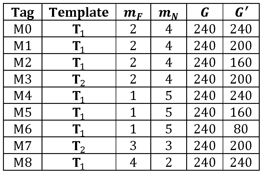
Fig. 15 shows the achieved spectral efficiencies of this solution. Each point in Fig. 15 represents a pair of SE values that can be simultaneously achieved by both users. The point (50, 0) on the x-axis corresponds to the spectral efficiency achievable when transmitting message 0 to user u = 0 and no message to user u = 1. Similarly, point (0, 5·^ on the y-axis corresponds to the spectral efficiency achievable when transmitting message 1 to user u = 1 and no messages to user u = 0. The line labelled Orthogonal MA" joins these two points and corresponds to the spectral efficiency pairs (SQ. S^ that can be achieved using orthogonal MA schemes (e.g., Time-Division Multiple Access - TDMA).
The curve labelled "Superposition bound" corresponds to the pairs of SE that can be achieved by an ideal transmission scheme that achieves SE pairs (50, 0) and (0, 5-L). In this context, "ideal transmission scheme" refers to a scheme using Gaussian signalling, infinite code word lengths and performing perfect far-user signal cancellation at the near user's receiver. The curve has been obtained as follows:
Compute the SNR p0 corresponding to AWGN channel capacity C(p0) = 50;
Compute the SNR p corresponding to AWGN channel capacity C^p^ = S ;
- The points (x, y) on the "Superposition bound" curve is obtained as
= C(apo)

J V aappt1 ++ l1 J
and C(z) = log2(l + z) is the capacity of the AWGN channel with SNR equal to z.
Points labelled "RA-CEMA" are the SE pairs achieved using the method herein disclosed with the matrix library of Fig. 12. These points correspond to SE pairs above the Orthogonal MA" line, therefore they cannot be achieved using orthogonal MA schemes.
The performance of RA-CEMA has been compared with AW-NOMA in terms of achievable rate pairs. Here, the far user (u = 1) is has ES F/N0 = 6 dB and the near user (u = 0) has ES N/N0 = 12 dB. Channel coding and rate matching are performed according to the LTE standard for turbo coding. Each block consists of G = 240 modulation symbols that are transmitted in as many REs. A rate pair is considered achievable if both users experience a block error rate below a given threshold: BLER≤ 10"1.
The considered modulation and coding schemes (MCS) are shown in Table 2. These schemes are a subset of those defined in the LTE standard. For each MCS, the BLER vs. Es/N0 characteristic has been evaluated through Monte Carlo simulation and the minimum value of Es/N0 needed to achieve BLER≤ 10"1 has been recorded (see "Es//V0 min." columns in Table 2).
Table 2: Modulation and coding schemes

9 QPSK 224 0.933333 1.1 26 16QAM 512 2.133333 7.1
10 QPSK 240 1 1.5 27 16QAM 544 2.266667 7.7
1 1 QPSK 256 1.066667 2 28 16QAM 576 2.4 8.2
12 QPSK 272 1.133333 2.3 29 16QAM 608 2.533333 8.8
13 QPSK 288 1.2 2.8 30 16QAM 640 2.666667 9.3
14 QPSK 304 1.266667 3.2 31 16QAM 672 2.8 9.8
15 QPSK 320 1.333333 3.6 32 16QAM 704 2.933333 10.3
16 QPSK 336 1.4 4 33 16QAM 736 3.066667 10.8
17 QPSK 352 1.466667 4.4 34 16QAM 768 3.2 1 1 .3
The achievable AW-NOMA rate pairs have been found using the following approach, as proposed in conventional solutions:
1 . Define a quality constraint to be satisfied for a set of rates to be considered achievable. As an example, we choose BLER≤ 10"1.
2. For each MCS le[l, ... ,34], determine the minimum SNR p(Z) needed to satisfy the quality constraint in a single-user transmission.
3. For each MCS Ze[l, ... ,34]
a. For the near user, set MCS I
b. Set a = ρ(ΐ)/(Ε5>Ν/Ν0)
c. For the far user, choose the highest-rate MCS among those that satisfy the quality constraint with p(Z) < (1 - a)ES F/N0
d. Calculate the BLER
i. If the rate pair is achievable at both the users, increment I and go back to step 3. a.
ii. If the rate pair is achievable at the far user, but not at the near user, increase a of Δα dB and go back to step 3.d.
iii. If the rate pair is achievable at the near user, but not at the far user, choose a MCS with lower rate for the far user and go back to step 3.d. iv. If the rate pair is unachievable at both the users, choose a MCS with lower rate for the far user, increase a of AadB and go back to step 3.d.
The step value Δα used to increase a must be carefully chosen relative to the characteristics of the MCS set. In particular, Δα should be smaller than the distance in dB between the BLER characteristics of two consecutive MCS. From Table 2, we see that the smallest
distance is 0.2 dB (between MCS 20 and MCS 21 , and between MCS 24 and MCS 25), therefore we use Δ„ = O.ldB.
Concerning the present solution (RA-CEMA) the described procedure cannot be applied because parameter a is not available. Therefore, in order to perform comparisons with AW- NOMA, we perform by simulation the following optimization:
RN* , RF* - *H(RN + RF) (15) where is the t-th multiplexing matrix, while RN (resp. RF) is the MCS rate of the near (resp. far) user. Results for the above are shown in Fig. 16. We notice that RA-CEMA approaches the same rates of AW-NOMA and, in some cases, exhibits better performance.
Furthermore, as described above the present invention also relates to corresponding methods in a transmitter and receiver. Any method according to the present invention may be implemented in a computer program, having code means, which when run by processing means causes the processing means to execute the steps of the method. The computer program is included in a computer readable medium of a computer program product. The computer readable medium may comprises of essentially any memory, such as a ROM (Read-Only Memory), a PROM (Programmable Read-Only Memory), an EPROM (Erasable PROM), a Flash memory, an EEPROM (Electrically Erasable PROM), or a hard disk drive. Moreover, it is realized by the skilled person that the present transmitter device 10 and receiver device 50 each comprises the necessary communication capabilities in the form of e.g., functions, means, units, elements, etc., for executing the present method. Examples of other such means, units, elements and functions are: processors, memory, encoders, decoders, mapping units, multipliers, interleavers, de-interleavers, modulators, demodulators, inputs, outputs, antennas, amplifiers, RX unit, TX unit, DSPs, MSDs, TCM encoder, TCM decoder, interfaces, communication protocols, etc. which are suitably arranged together. Examples of transmitter devices are base stations, remote radio heads, relay devices, access points or any other network control nodes having the corresponding capabilities. Further, receiver devices are any communication devices adapted to receive DL signals in a wireless communication system and may e.g. be a UE in an LTE system. The present solution is also easily combined with other transmission techniques of conventional solution such as Multiple Input Multiple Output (MIMO) and Orthogonal Frequency Division Multiplexing (OFDM).
Especially, the processors of the present user device or access node device may comprise, e.g., one or more instances of a Central Processing Unit (CPU), a processing unit, a processing circuit, a processor, an Application Specific Integrated Circuit (ASIC), a microprocessor, or other processing logic that may interpret and execute instructions. The expression "processor" may thus represent a processing circuitry comprising a plurality of processing circuits, such as, e.g., any, some or all of the ones mentioned above. The processing circuitry may further perform data processing functions for inputting, outputting, and processing of data comprising data buffering and device control functions, such as call processing control, user interface control, or the like.
Finally, it should be understood that the present invention is not limited to the embodiments described above, but also relates to and incorporates all embodiments within the scope of the appended independent claims.
Claims
1 . Transmitter device (10) adapted to:
select a plurality of receiver devices (50) = 1, 2, ... , U having different downlink channel qualities;
determine for each user a code rate Ru, a modulation order mu, and number of Resource Elements, REs, Gu;
obtain a multiplexing matrix M based on the determined code rates ffu=i,2,...,u> modulation orders r u= li2,...,u ar,d number of REs Gu=1 2i υ for said plurality of receiver devices (50);
independently encode for each receiver device (50) an information message bu = (bu{0), ... , bu(Ku - 1)) so as to obtain an encoded message eu = (eu(0), ... , eu(Eu - 1)); multiplex the encoded information messages e0, ... , eu_1 into a label vector 1 = (Z(0), ... , l(G— 1)) having m-bit labels based on said multiplexing matrix M;
using each label of said label vector 1 = (Z(0), l(G— 1)) to select a modulation symbol from a modulation constellation of order m so as to obtain a symbol vector x = (x(0), ... , x(G— 1)) for said multiplexed encoded information messages e0, ... , eu_1; and
transmit a downlink signal 5 comprising said symbol vector x = (x(0), ... , x(G— 1)) .
2. Transmitter device (10) according to claim 1 , further adapted to:
receive the downlink channel qualities from said plurality of receiver devices (50); and/or
estimate the downlink channel qualities by measuring corresponding uplink channels for said plurality of receiver devices (50).
3. Transmitter device (10) according to claim 2, wherein the downlink channel qualities are based on Signal-to-Noise Ratio, SNR, or Signal-to-lnterference and Noise Ratio, SI NR, estimations.
4. Transmitter device (10) according to any of the preceding claims, further adapted to obtain said multiplexing matrix M from a pre-computed library (16) comprising a plurality of multiplexing matrices ΜΛ or representations thereof.
5. Transmitter device (10) according to claim 4, wherein said pre-computed library (16) comprises a plurality of template matrices having size m x G, where m = m1 + m2 -\ h
mu and G = max^, and said transmitter device (10) further being adapted to obtain said multiplexing matrix M by using said plurality of template matrices and a design parameter G' having a value in the range from 1 to G and obtained through a simulation based optimization procedure.
6. Transmitter device (10) according to claim 4 or 5, further adapted to signal an indication of said multiplexing matrix M to said plurality of receiver devices (50).
7. Transmitter device (10) according to claim 5, wherein said indication is an index in said pre-computed library (16) for said multiplexing matrix M, and further being adapted to signal to each of said plurality of receiver devices (50) their respective associated receiver device index u = 1, 2, ... , U.
8. Transmitter device (10) according to any of the preceding claims, wherein at least two column elements of at least one column of said multiplexing matrix M are associated with different receiver devices (50) u = 1, 2, ... , U.
9. Transmitter device (10) according to any of the preceding claims, wherein said multiplexing matrix M has size m x G, where m = m1 + m2 -\ \- mu and G = max^G^ ... , Gu).
10. Transmitter device (10) according to claim 9, further adapted to transmit said downlink signal 5 with G number of time-frequency REs.
1 1 . Receiver device (50) adapted to:
receive a downlink signal 5 comprising a symbol vector x = (x(0), ... , x(G— 1)) according to any of the preceding claims;
detect and de-multiplex said downlink signal 5 using a multiplexing matrix M associated with said symbol vector x = (x(0), ... , x(G— 1)); and
decode said detected and de-multiplex downlink signal 5 so as to obtain an estimate of an information message bu = (bu(0), ... , bu(Ku— 1)) associated with said receiver device (50).
12. Receiver device (50) according to claim 1 1 , further adapted to obtain said multiplexing matrix M from a pre-computed library (54) comprising a plurality of multiplexing matrices ΜΛ or representations thereof.
13. Receiver device (50) according to claim 12, wherein said pre-computed library (54) comprises a plurality of template matrices having size m x G, where m = m1 + m2 + ... + mu and G = max^G^ Gu), and said receiver device (50) further being adapted to obtain said multiplexing matrix M by using said plurality of template matrices and a design parameter G' having a value in the range from 1 to G.
14. Receiver device (50) according to claim 12 or 13, further adapted to receive a signal comprising an indication of said multiplexing matrix M and a receiver device (50) index u = 1, 2, ... , U for said receiver device (50).
15. Transmission method comprising the steps of:
selecting (100) a plurality of receiver devices (50) u = l, 2, ... , U having different downlink channel qualities;
determining (1 10) for each user a code rate Ru, a modulation order mu, and number of Resource Elements, REs, Gu;
obtaining (120) a multiplexing matrix M based on the determined code rates Ru=i,2,...,u> modulation orders mu=i,2,...,u and number of REs Gu=i,2,...,u for said plurality of receiver devices (50);
independently encoding (130) for each receiver device (50) an information message bu = (fru(0), ... , bu(Ku - 1)) so as to obtain an encoded message eu = (eu(0), ... , eu(Eu - 1)); multiplexing (140) the encoded information messages e0, ... , ε^! into a label vector
1 = (Z(0), ... , l(G— 1)) having m-bit labels based on said multiplexing matrix M;
using (150) each label of said label vector 1 = (Z(0), ... , l(G— 1)) to select a modulation symbol from a modulation constellation of order m so as to obtain a symbol vector x = (x(0), ... , x(G— 1)) for said multiplexed encoded information messages e0, ... , eu_1; and
transmitting (160) a downlink signal 5 comprising said symbol vector x = (z(0) z(G - l)).
16. Receiving method comprising the steps of:
receiving (200) a downlink signal 5 comprising a symbol vector x = (x(0), ... , x(G— 1))
detecting and de-multiplexing (210) said downlink signal 5 using a multiplexing matrix M associated with said symbol vector x = (x(0), ... , x(G— 1)); and
decoding (220) said detected and de-multiplex downlink signal 5 so as to obtain an estimate of an information message bu = (fru(0), bu(Ku— 1)) associated with said receiver device (50).
17. A computer program with a program code for performing the method according to claim 15 or 16, when the computer program runs on a computer.
Priority Applications (12)
| Application Number | Priority Date | Filing Date | Title |
|---|---|---|---|
| PCT/EP2014/056365 WO2015144250A1 (en) | 2014-03-28 | 2014-03-28 | Transmitter and receiver devices and methods thereof |
| CN201480077323.9A CN106464645B (en) | 2014-03-28 | 2014-03-28 | Sending device and receiving device and its method |
| EP14714680.7A EP3123684B1 (en) | 2014-03-28 | 2014-03-28 | Transmitter devices and method thereof |
| CN201580014990.7A CN106464648B (en) | 2014-03-28 | 2015-01-30 | Data transmission device in multiuser downstream cellular system |
| CA2944066A CA2944066C (en) | 2014-03-28 | 2015-01-30 | Method and apparatus for data transmission in a multiuser downlink cellular system |
| BR112016022248A BR112016022248A2 (en) | 2014-03-28 | 2015-01-30 | METHOD AND APPARATUS FOR DATA TRANSMISSION IN A MULTIPLE USER DOWNLINK CELLULAR SYSTEM |
| PCT/EP2015/051934 WO2015144343A1 (en) | 2014-03-28 | 2015-01-30 | Method and apparatus for data transmission in a multiuser downlink cellular system |
| EP15703043.8A EP3111608B1 (en) | 2014-03-28 | 2015-01-30 | Method and apparatus for data transmission in a multiuser downlink cellular system |
| CN201910906897.7A CN110661596B (en) | 2014-03-28 | 2015-01-30 | Data transmission method and device in multi-user downlink cellular system |
| EP18189211.8A EP3435612A1 (en) | 2014-03-28 | 2015-01-30 | Method and apparatus for data transmission in a multiuser downlink cellular system |
| US15/277,771 US10148481B2 (en) | 2014-03-28 | 2016-09-27 | Method and apparatus for data transmission in a multiuser downlink cellular system |
| US16/135,964 US10887150B2 (en) | 2014-03-28 | 2018-09-19 | Method and apparatus for data transmission in a multiuser downlink cellular system |
Applications Claiming Priority (1)
| Application Number | Priority Date | Filing Date | Title |
|---|---|---|---|
| PCT/EP2014/056365 WO2015144250A1 (en) | 2014-03-28 | 2014-03-28 | Transmitter and receiver devices and methods thereof |
Publications (1)
| Publication Number | Publication Date |
|---|---|
| WO2015144250A1 true WO2015144250A1 (en) | 2015-10-01 |
Family
ID=50424237
Family Applications (2)
| Application Number | Title | Priority Date | Filing Date |
|---|---|---|---|
| PCT/EP2014/056365 WO2015144250A1 (en) | 2014-03-28 | 2014-03-28 | Transmitter and receiver devices and methods thereof |
| PCT/EP2015/051934 WO2015144343A1 (en) | 2014-03-28 | 2015-01-30 | Method and apparatus for data transmission in a multiuser downlink cellular system |
Family Applications After (1)
| Application Number | Title | Priority Date | Filing Date |
|---|---|---|---|
| PCT/EP2015/051934 WO2015144343A1 (en) | 2014-03-28 | 2015-01-30 | Method and apparatus for data transmission in a multiuser downlink cellular system |
Country Status (6)
| Country | Link |
|---|---|
| US (2) | US10148481B2 (en) |
| EP (3) | EP3123684B1 (en) |
| CN (3) | CN106464645B (en) |
| BR (1) | BR112016022248A2 (en) |
| CA (1) | CA2944066C (en) |
| WO (2) | WO2015144250A1 (en) |
Cited By (4)
| Publication number | Priority date | Publication date | Assignee | Title |
|---|---|---|---|---|
| CN107682128A (en) * | 2017-08-31 | 2018-02-09 | 宇龙计算机通信科技(深圳)有限公司 | Data transmission method, device, equipment and storage medium |
| US10148481B2 (en) | 2014-03-28 | 2018-12-04 | Huawei Technologies Co., Ltd. | Method and apparatus for data transmission in a multiuser downlink cellular system |
| WO2019192719A1 (en) * | 2018-04-06 | 2019-10-10 | Telefonaktiebolaget Lm Ericsson (Publ) | Message and rate based user grouping in non-orthogonal multiple access (noma) networks |
| EP3398270B1 (en) * | 2015-12-29 | 2020-09-09 | Thales | Method for unambiguous and secret coding for transmission over a propagation channel with capacity advantage |
Families Citing this family (16)
| Publication number | Priority date | Publication date | Assignee | Title |
|---|---|---|---|---|
| WO2019005078A1 (en) * | 2017-06-29 | 2019-01-03 | Intel Corporation | Identification of a device for spatial frequency reuse |
| US10560304B2 (en) * | 2017-07-12 | 2020-02-11 | Qualcomm Incorporated | Techniques and apparatuses for multiplexing schemes for millimeter wave downlink single carrier waveforms |
| CN109391457A (en) * | 2017-08-04 | 2019-02-26 | 财团法人工业技术研究院 | Transmitter and transmission method suitable for non-orthogonal multiple access communication system |
| CN109561509B (en) * | 2017-09-25 | 2023-04-07 | 中兴通讯股份有限公司 | Method and device for reverse resource allocation of wireless communication system |
| CN109802756A (en) * | 2017-11-17 | 2019-05-24 | 华为技术有限公司 | Information processing method and radio transmission apparatus |
| WO2019095426A1 (en) | 2017-11-17 | 2019-05-23 | 华为技术有限公司 | Information processing method and wireless transmission device |
| US10999035B2 (en) * | 2017-11-29 | 2021-05-04 | Electronics And Telecommunications Research Institute | Method for mitigation of multiple access interference in mobile communication system and apparatus for the same |
| CN110061769A (en) | 2018-01-18 | 2019-07-26 | 华为技术有限公司 | The method and apparatus for sending data |
| CN110061804B (en) * | 2018-01-19 | 2021-01-29 | 华为技术有限公司 | Communication, MCS receiving and notifying method and equipment |
| US10848228B2 (en) * | 2018-02-16 | 2020-11-24 | Qualcomm Incorporated | Modulation and coding scheme and channel quality indicator for high reliability |
| WO2020013827A1 (en) * | 2018-07-12 | 2020-01-16 | Intel Corporation (A Corporation Of Delaware) | Non-orthogonal multiple-access and multi-finger beamforming |
| CN112514292B (en) * | 2018-08-08 | 2022-03-29 | 华为技术有限公司 | Transmitting device and receiving device for efficient transmission of information messages |
| KR20210046348A (en) * | 2019-10-18 | 2021-04-28 | 삼성전자주식회사 | Memory system for flexibly allocating memory for multiple processors and operating method thereof |
| KR102443456B1 (en) * | 2020-02-06 | 2022-09-16 | 삼성전자 주식회사 | The method for allocating codebook and user scheduling for maximizing sum frequency rate in non-orthogonal multiple access system |
| TWI721806B (en) * | 2020-03-04 | 2021-03-11 | 國立高雄科技大學 | Vital sign sensing method and system using communication device |
| CN114944890B (en) * | 2022-07-21 | 2022-10-25 | 北京全路通信信号研究设计院集团有限公司 | Transponder message transmission processing method and system |
Citations (2)
| Publication number | Priority date | Publication date | Assignee | Title |
|---|---|---|---|---|
| EP2299737A1 (en) * | 2008-07-03 | 2011-03-23 | Fujitsu Limited | Base station apparatus and data mapping method |
| EP2326053A1 (en) * | 2008-09-12 | 2011-05-25 | Fujitsu Limited | Transmission device, reception device, transmission method, and reception method |
Family Cites Families (30)
| Publication number | Priority date | Publication date | Assignee | Title |
|---|---|---|---|---|
| US7688899B2 (en) * | 2001-05-17 | 2010-03-30 | Qualcomm Incorporated | Method and apparatus for processing data for transmission in a multi-channel communication system using selective channel inversion |
| KR100754722B1 (en) * | 2004-05-12 | 2007-09-03 | 삼성전자주식회사 | Apparatus and method for data transmission/receiving using channel state information in a wireless communication system |
| KR100705501B1 (en) * | 2005-11-16 | 2007-04-09 | 한국전자통신연구원 | Method for downlink, uplink scheduling and resource assignment according to space division multiplexing in base station of mobile communication system |
| CN101043500B (en) * | 2006-06-15 | 2010-05-12 | 华为技术有限公司 | Method for determining inverse data modulation coding mode and access terminal thereof |
| TWI479933B (en) * | 2006-10-10 | 2015-04-01 | Interdigital Tech Corp | Method and apparatus for sending feedback for a downlink shared service transmitted to a plurality of wireless transmit/receive units |
| TR201905158T4 (en) * | 2007-06-05 | 2019-05-21 | Constellation Designs Inc | Signaling method and apparatus with capacity optimized star clusters. |
| US8265175B2 (en) * | 2007-06-05 | 2012-09-11 | Constellation Designs, Inc. | Methods and apparatuses for signaling with geometric constellations |
| ATE518324T1 (en) * | 2007-07-24 | 2011-08-15 | Alcatel Lucent | WIRELESS ACCESS SYSTEM AND TRANSMISSION METHOD |
| KR101467791B1 (en) * | 2007-11-05 | 2014-12-03 | 엘지전자 주식회사 | Method for multiplexing data and control information |
| US8315339B2 (en) * | 2009-05-05 | 2012-11-20 | Telefonaktiebolaget Lm Ericsson (Publ) | Channel estimation |
| CN101572948B (en) * | 2009-06-09 | 2011-05-04 | 华为技术有限公司 | Uplink scheduling method in wireless communication system, base station and wireless communication system |
| KR101567368B1 (en) * | 2009-07-02 | 2015-11-09 | 삼성전자주식회사 | Apparatus and method for managing resource to decrasse inter cell interference in a broadband wireless commmunication system |
| WO2011024474A1 (en) * | 2009-08-28 | 2011-03-03 | パナソニック株式会社 | Wireless communication apparatus and response control method |
| US8553598B2 (en) * | 2009-11-09 | 2013-10-08 | Telefonaktiebolageta LM Ericsson (publ) | Network coding mode selector |
| CN101814979B (en) * | 2009-12-07 | 2013-02-06 | 南京邮电大学 | Transmitting-receiving two-end combined design method of correlative multi-antenna system |
| EP2541984A1 (en) * | 2010-02-23 | 2013-01-02 | Nec Corporation | Wireless base station and adaptive modulation control method thereof |
| US9019922B2 (en) * | 2010-07-21 | 2015-04-28 | Panasonic Intellectual Property Corporation Of America | Base station, terminal, transmission method and reception method |
| CN102035785B (en) * | 2010-11-12 | 2013-04-03 | 清华大学 | Frequency-division duplexing transmission method for wideband wireless communication system |
| CN102035786B (en) * | 2010-11-12 | 2013-05-01 | 清华大学 | Time division duplex transmission method for broadband wireless communication system |
| US20120182895A1 (en) * | 2011-01-13 | 2012-07-19 | Electronics And Telecommunications Research Institute | Apparatus and method for transmitting and receiving channel state information |
| CN102638431A (en) * | 2011-02-10 | 2012-08-15 | 富士通株式会社 | Bit dispensing equipment, transmitter, bit distribution method and power distribution method |
| US8774303B2 (en) * | 2011-06-29 | 2014-07-08 | Electronics And Telecommunications Research Institute | Wireless communication method and apparatus using adaptive transmission polarization control |
| CN103490805B (en) | 2011-11-08 | 2016-09-07 | 华为技术有限公司 | The method and apparatus sending data stream in mimo system |
| US8995545B2 (en) * | 2012-07-30 | 2015-03-31 | Telefonaktiebolaget L M Ericsson (Publ) | Base station and method for transmitting control information to a user equipment (UE) |
| US9407343B2 (en) * | 2012-08-31 | 2016-08-02 | Google Technology Holdings LLC | Method and apparatus for mitigating downlink interference |
| WO2014182135A1 (en) * | 2013-05-09 | 2014-11-13 | 엘지전자 주식회사 | Broadcast signal transmission apparatus, broadcast signal reception apparatus, broadcast signal transmission method, and broadcast signal reception method |
| CN109525371B (en) | 2013-10-31 | 2020-10-23 | 华为技术有限公司 | Method and node for equal error protection in wireless communication system using adaptive hierarchical modulation |
| EP3096556A4 (en) * | 2014-01-15 | 2017-08-23 | Sharp Kabushiki Kaisha | Terminal device, base station device, and integrated circuit |
| CN106464645B (en) | 2014-03-28 | 2019-11-12 | 华为技术有限公司 | Sending device and receiving device and its method |
| EP3335344B1 (en) * | 2015-08-14 | 2020-03-11 | Telefonaktiebolaget LM Ericsson (PUBL) | Multiple csi reports for multi-user superposition transmission |
-
2014
- 2014-03-28 CN CN201480077323.9A patent/CN106464645B/en active Active
- 2014-03-28 EP EP14714680.7A patent/EP3123684B1/en active Active
- 2014-03-28 WO PCT/EP2014/056365 patent/WO2015144250A1/en active Application Filing
-
2015
- 2015-01-30 WO PCT/EP2015/051934 patent/WO2015144343A1/en active Application Filing
- 2015-01-30 EP EP18189211.8A patent/EP3435612A1/en active Pending
- 2015-01-30 EP EP15703043.8A patent/EP3111608B1/en active Active
- 2015-01-30 CA CA2944066A patent/CA2944066C/en not_active Expired - Fee Related
- 2015-01-30 CN CN201910906897.7A patent/CN110661596B/en active Active
- 2015-01-30 CN CN201580014990.7A patent/CN106464648B/en active Active
- 2015-01-30 BR BR112016022248A patent/BR112016022248A2/en not_active Application Discontinuation
-
2016
- 2016-09-27 US US15/277,771 patent/US10148481B2/en active Active
-
2018
- 2018-09-19 US US16/135,964 patent/US10887150B2/en active Active
Patent Citations (2)
| Publication number | Priority date | Publication date | Assignee | Title |
|---|---|---|---|---|
| EP2299737A1 (en) * | 2008-07-03 | 2011-03-23 | Fujitsu Limited | Base station apparatus and data mapping method |
| EP2326053A1 (en) * | 2008-09-12 | 2011-05-25 | Fujitsu Limited | Transmission device, reception device, transmission method, and reception method |
Cited By (7)
| Publication number | Priority date | Publication date | Assignee | Title |
|---|---|---|---|---|
| US10148481B2 (en) | 2014-03-28 | 2018-12-04 | Huawei Technologies Co., Ltd. | Method and apparatus for data transmission in a multiuser downlink cellular system |
| US10887150B2 (en) | 2014-03-28 | 2021-01-05 | Huawei Technologies Co., Ltd. | Method and apparatus for data transmission in a multiuser downlink cellular system |
| EP3398270B1 (en) * | 2015-12-29 | 2020-09-09 | Thales | Method for unambiguous and secret coding for transmission over a propagation channel with capacity advantage |
| CN107682128A (en) * | 2017-08-31 | 2018-02-09 | 宇龙计算机通信科技(深圳)有限公司 | Data transmission method, device, equipment and storage medium |
| CN107682128B (en) * | 2017-08-31 | 2020-06-05 | 宇龙计算机通信科技(深圳)有限公司 | Data transmission method, device, equipment and storage medium |
| WO2019192719A1 (en) * | 2018-04-06 | 2019-10-10 | Telefonaktiebolaget Lm Ericsson (Publ) | Message and rate based user grouping in non-orthogonal multiple access (noma) networks |
| US11012177B2 (en) | 2018-04-06 | 2021-05-18 | Telefonaktiebolaget Lm Ericsson (Publ) | Message and rate based user grouping in non-orthogonal multiple access (NOMA) networks |
Also Published As
| Publication number | Publication date |
|---|---|
| CN110661596A (en) | 2020-01-07 |
| CA2944066A1 (en) | 2015-10-01 |
| CN106464645A (en) | 2017-02-22 |
| WO2015144343A1 (en) | 2015-10-01 |
| US20170041178A1 (en) | 2017-02-09 |
| CN110661596B (en) | 2021-10-01 |
| US10148481B2 (en) | 2018-12-04 |
| EP3111608B1 (en) | 2018-11-07 |
| EP3123684B1 (en) | 2020-02-12 |
| BR112016022248A2 (en) | 2017-08-15 |
| US10887150B2 (en) | 2021-01-05 |
| CN106464648A (en) | 2017-02-22 |
| CN106464648B (en) | 2019-10-18 |
| EP3111608A1 (en) | 2017-01-04 |
| CA2944066C (en) | 2018-07-31 |
| EP3435612A1 (en) | 2019-01-30 |
| US20190020525A1 (en) | 2019-01-17 |
| CN106464645B (en) | 2019-11-12 |
| EP3123684A1 (en) | 2017-02-01 |
Similar Documents
| Publication | Publication Date | Title |
|---|---|---|
| EP3123684B1 (en) | Transmitter devices and method thereof | |
| US10771186B2 (en) | Transmitting device, receiving device and methods thereof | |
| JP4843033B2 (en) | Coding and modulation of multiple data streams in a communication system | |
| JP6465810B2 (en) | Signal transmission / reception method and apparatus using multiple modulation techniques in wireless communication system | |
| RU2536371C2 (en) | Determining wireless link quality based on received signals | |
| JP5830158B2 (en) | Terminal apparatus and wireless communication method | |
| KR20140081751A (en) | Method and apparatus for transmitting/receiving signal in communication system | |
| US9985746B2 (en) | Transmitter and receiver devices and methods thereof | |
| KR20080026620A (en) | Robust rank prediction for a mimo system | |
| KR20080045137A (en) | Multicarrier communication system, multicarrier communication apparatus and cqi reporting method | |
| WO2013168790A1 (en) | Transmitting device, receiving device, transmitting method, program, and integrated circuit | |
| EP2191581A2 (en) | Rate matching to maintain code block resource element boundaries | |
| US20100080315A1 (en) | Mimo transmission mode selecting method and wireless communication equipment | |
| KR20090132739A (en) | Apparatus and method for power control in mobile communication system | |
| JP4792527B2 (en) | Transmission method and transmission apparatus | |
| JP4536778B2 (en) | Apparatus and method for achieving cyclic delay diversity | |
| JP6565089B2 (en) | Frame error rate prediction apparatus, radio communication apparatus, and radio communication system | |
| JP5029769B2 (en) | Transmission method and transmission apparatus | |
| JP6565088B2 (en) | Frame error rate prediction apparatus, radio communication apparatus and radio communication system using the same | |
| JP6565087B2 (en) | Frame error rate prediction apparatus, radio communication apparatus and radio communication system using the same | |
| JP7095851B2 (en) | Frame error rate predictor, wireless communication device and wireless communication system using it | |
| JP5024415B2 (en) | Control channel information transmission method, base station and user terminal using the same |
Legal Events
| Date | Code | Title | Description |
|---|---|---|---|
| 121 | Ep: the epo has been informed by wipo that ep was designated in this application |
Ref document number: 14714680 Country of ref document: EP Kind code of ref document: A1 |
|
| NENP | Non-entry into the national phase |
Ref country code: DE |
|
| REEP | Request for entry into the european phase |
Ref document number: 2014714680 Country of ref document: EP |
|
| WWE | Wipo information: entry into national phase |
Ref document number: 2014714680 Country of ref document: EP |