EP3335344B1 - Multiple csi reports for multi-user superposition transmission - Google Patents
Multiple csi reports for multi-user superposition transmission Download PDFInfo
- Publication number
- EP3335344B1 EP3335344B1 EP16757739.4A EP16757739A EP3335344B1 EP 3335344 B1 EP3335344 B1 EP 3335344B1 EP 16757739 A EP16757739 A EP 16757739A EP 3335344 B1 EP3335344 B1 EP 3335344B1
- Authority
- EP
- European Patent Office
- Prior art keywords
- csi
- transmission
- cqi
- reports
- user superposition
- Prior art date
- Legal status (The legal status is an assumption and is not a legal conclusion. Google has not performed a legal analysis and makes no representation as to the accuracy of the status listed.)
- Active
Links
- 230000005540 biological transmission Effects 0.000 title claims description 212
- 238000000034 method Methods 0.000 claims description 96
- 229920006934 PMI Polymers 0.000 claims description 51
- 238000012545 processing Methods 0.000 claims description 37
- 238000004590 computer program Methods 0.000 claims description 10
- 239000011159 matrix material Substances 0.000 claims description 7
- 230000003287 optical effect Effects 0.000 claims 1
- 230000008569 process Effects 0.000 description 40
- 230000011664 signaling Effects 0.000 description 23
- 238000005259 measurement Methods 0.000 description 20
- 238000013459 approach Methods 0.000 description 11
- 238000010586 diagram Methods 0.000 description 8
- 238000004891 communication Methods 0.000 description 7
- 230000006870 function Effects 0.000 description 4
- 230000008901 benefit Effects 0.000 description 3
- 230000002452 interceptive effect Effects 0.000 description 3
- 230000000670 limiting effect Effects 0.000 description 3
- 230000000737 periodic effect Effects 0.000 description 3
- 238000003491 array Methods 0.000 description 2
- 230000010267 cellular communication Effects 0.000 description 2
- 235000019800 disodium phosphate Nutrition 0.000 description 2
- 238000005516 engineering process Methods 0.000 description 2
- 239000000796 flavoring agent Substances 0.000 description 2
- 235000019634 flavors Nutrition 0.000 description 2
- 239000010410 layer Substances 0.000 description 2
- 230000005055 memory storage Effects 0.000 description 2
- 238000012986 modification Methods 0.000 description 2
- 230000004048 modification Effects 0.000 description 2
- 230000006399 behavior Effects 0.000 description 1
- 230000001413 cellular effect Effects 0.000 description 1
- 230000003247 decreasing effect Effects 0.000 description 1
- 230000001419 dependent effect Effects 0.000 description 1
- 238000001514 detection method Methods 0.000 description 1
- 238000011156 evaluation Methods 0.000 description 1
- 239000011229 interlayer Substances 0.000 description 1
- 230000007774 longterm Effects 0.000 description 1
- 238000013507 mapping Methods 0.000 description 1
- 238000010295 mobile communication Methods 0.000 description 1
- 230000009467 reduction Effects 0.000 description 1
- 230000002829 reductive effect Effects 0.000 description 1
- 230000004044 response Effects 0.000 description 1
- 230000003068 static effect Effects 0.000 description 1
- 230000001960 triggered effect Effects 0.000 description 1
Images


Classifications
-
- H—ELECTRICITY
- H04—ELECTRIC COMMUNICATION TECHNIQUE
- H04L—TRANSMISSION OF DIGITAL INFORMATION, e.g. TELEGRAPHIC COMMUNICATION
- H04L5/00—Arrangements affording multiple use of the transmission path
- H04L5/003—Arrangements for allocating sub-channels of the transmission path
- H04L5/0048—Allocation of pilot signals, i.e. of signals known to the receiver
-
- H—ELECTRICITY
- H04—ELECTRIC COMMUNICATION TECHNIQUE
- H04B—TRANSMISSION
- H04B7/00—Radio transmission systems, i.e. using radiation field
- H04B7/02—Diversity systems; Multi-antenna system, i.e. transmission or reception using multiple antennas
- H04B7/04—Diversity systems; Multi-antenna system, i.e. transmission or reception using multiple antennas using two or more spaced independent antennas
- H04B7/0413—MIMO systems
- H04B7/0452—Multi-user MIMO systems
-
- H—ELECTRICITY
- H04—ELECTRIC COMMUNICATION TECHNIQUE
- H04B—TRANSMISSION
- H04B7/00—Radio transmission systems, i.e. using radiation field
- H04B7/02—Diversity systems; Multi-antenna system, i.e. transmission or reception using multiple antennas
- H04B7/04—Diversity systems; Multi-antenna system, i.e. transmission or reception using multiple antennas using two or more spaced independent antennas
- H04B7/0413—MIMO systems
- H04B7/0456—Selection of precoding matrices or codebooks, e.g. using matrices antenna weighting
-
- H—ELECTRICITY
- H04—ELECTRIC COMMUNICATION TECHNIQUE
- H04B—TRANSMISSION
- H04B7/00—Radio transmission systems, i.e. using radiation field
- H04B7/02—Diversity systems; Multi-antenna system, i.e. transmission or reception using multiple antennas
- H04B7/04—Diversity systems; Multi-antenna system, i.e. transmission or reception using multiple antennas using two or more spaced independent antennas
- H04B7/06—Diversity systems; Multi-antenna system, i.e. transmission or reception using multiple antennas using two or more spaced independent antennas at the transmitting station
- H04B7/0613—Diversity systems; Multi-antenna system, i.e. transmission or reception using multiple antennas using two or more spaced independent antennas at the transmitting station using simultaneous transmission
- H04B7/0615—Diversity systems; Multi-antenna system, i.e. transmission or reception using multiple antennas using two or more spaced independent antennas at the transmitting station using simultaneous transmission of weighted versions of same signal
- H04B7/0619—Diversity systems; Multi-antenna system, i.e. transmission or reception using multiple antennas using two or more spaced independent antennas at the transmitting station using simultaneous transmission of weighted versions of same signal using feedback from receiving side
- H04B7/0621—Feedback content
- H04B7/0626—Channel coefficients, e.g. channel state information [CSI]
-
- H—ELECTRICITY
- H04—ELECTRIC COMMUNICATION TECHNIQUE
- H04B—TRANSMISSION
- H04B7/00—Radio transmission systems, i.e. using radiation field
- H04B7/02—Diversity systems; Multi-antenna system, i.e. transmission or reception using multiple antennas
- H04B7/04—Diversity systems; Multi-antenna system, i.e. transmission or reception using multiple antennas using two or more spaced independent antennas
- H04B7/06—Diversity systems; Multi-antenna system, i.e. transmission or reception using multiple antennas using two or more spaced independent antennas at the transmitting station
- H04B7/0613—Diversity systems; Multi-antenna system, i.e. transmission or reception using multiple antennas using two or more spaced independent antennas at the transmitting station using simultaneous transmission
- H04B7/0615—Diversity systems; Multi-antenna system, i.e. transmission or reception using multiple antennas using two or more spaced independent antennas at the transmitting station using simultaneous transmission of weighted versions of same signal
- H04B7/0619—Diversity systems; Multi-antenna system, i.e. transmission or reception using multiple antennas using two or more spaced independent antennas at the transmitting station using simultaneous transmission of weighted versions of same signal using feedback from receiving side
- H04B7/0621—Feedback content
- H04B7/0632—Channel quality parameters, e.g. channel quality indicator [CQI]
-
- H—ELECTRICITY
- H04—ELECTRIC COMMUNICATION TECHNIQUE
- H04B—TRANSMISSION
- H04B7/00—Radio transmission systems, i.e. using radiation field
- H04B7/02—Diversity systems; Multi-antenna system, i.e. transmission or reception using multiple antennas
- H04B7/04—Diversity systems; Multi-antenna system, i.e. transmission or reception using multiple antennas using two or more spaced independent antennas
- H04B7/06—Diversity systems; Multi-antenna system, i.e. transmission or reception using multiple antennas using two or more spaced independent antennas at the transmitting station
- H04B7/0613—Diversity systems; Multi-antenna system, i.e. transmission or reception using multiple antennas using two or more spaced independent antennas at the transmitting station using simultaneous transmission
- H04B7/0615—Diversity systems; Multi-antenna system, i.e. transmission or reception using multiple antennas using two or more spaced independent antennas at the transmitting station using simultaneous transmission of weighted versions of same signal
- H04B7/0619—Diversity systems; Multi-antenna system, i.e. transmission or reception using multiple antennas using two or more spaced independent antennas at the transmitting station using simultaneous transmission of weighted versions of same signal using feedback from receiving side
- H04B7/0636—Feedback format
- H04B7/0639—Using selective indices, e.g. of a codebook, e.g. pre-distortion matrix index [PMI] or for beam selection
-
- H—ELECTRICITY
- H04—ELECTRIC COMMUNICATION TECHNIQUE
- H04L—TRANSMISSION OF DIGITAL INFORMATION, e.g. TELEGRAPHIC COMMUNICATION
- H04L1/00—Arrangements for detecting or preventing errors in the information received
- H04L1/0001—Systems modifying transmission characteristics according to link quality, e.g. power backoff
- H04L1/0023—Systems modifying transmission characteristics according to link quality, e.g. power backoff characterised by the signalling
- H04L1/0026—Transmission of channel quality indication
-
- H—ELECTRICITY
- H04—ELECTRIC COMMUNICATION TECHNIQUE
- H04L—TRANSMISSION OF DIGITAL INFORMATION, e.g. TELEGRAPHIC COMMUNICATION
- H04L27/00—Modulated-carrier systems
- H04L27/32—Carrier systems characterised by combinations of two or more of the types covered by groups H04L27/02, H04L27/10, H04L27/18 or H04L27/26
- H04L27/34—Amplitude- and phase-modulated carrier systems, e.g. quadrature-amplitude modulated carrier systems
- H04L27/345—Modifications of the signal space to allow the transmission of additional information
-
- H—ELECTRICITY
- H04—ELECTRIC COMMUNICATION TECHNIQUE
- H04L—TRANSMISSION OF DIGITAL INFORMATION, e.g. TELEGRAPHIC COMMUNICATION
- H04L5/00—Arrangements affording multiple use of the transmission path
- H04L5/003—Arrangements for allocating sub-channels of the transmission path
- H04L5/0037—Inter-user or inter-terminal allocation
-
- H—ELECTRICITY
- H04—ELECTRIC COMMUNICATION TECHNIQUE
- H04L—TRANSMISSION OF DIGITAL INFORMATION, e.g. TELEGRAPHIC COMMUNICATION
- H04L5/00—Arrangements affording multiple use of the transmission path
- H04L5/003—Arrangements for allocating sub-channels of the transmission path
- H04L5/0053—Allocation of signaling, i.e. of overhead other than pilot signals
- H04L5/0057—Physical resource allocation for CQI
-
- H—ELECTRICITY
- H04—ELECTRIC COMMUNICATION TECHNIQUE
- H04L—TRANSMISSION OF DIGITAL INFORMATION, e.g. TELEGRAPHIC COMMUNICATION
- H04L5/00—Arrangements affording multiple use of the transmission path
- H04L5/003—Arrangements for allocating sub-channels of the transmission path
- H04L5/0058—Allocation criteria
- H04L5/006—Quality of the received signal, e.g. BER, SNR, water filling
-
- H—ELECTRICITY
- H04—ELECTRIC COMMUNICATION TECHNIQUE
- H04W—WIRELESS COMMUNICATION NETWORKS
- H04W52/00—Power management, e.g. TPC [Transmission Power Control], power saving or power classes
- H04W52/04—TPC
- H04W52/30—TPC using constraints in the total amount of available transmission power
- H04W52/36—TPC using constraints in the total amount of available transmission power with a discrete range or set of values, e.g. step size, ramping or offsets
- H04W52/367—Power values between minimum and maximum limits, e.g. dynamic range
-
- H—ELECTRICITY
- H04—ELECTRIC COMMUNICATION TECHNIQUE
- H04W—WIRELESS COMMUNICATION NETWORKS
- H04W72/00—Local resource management
- H04W72/12—Wireless traffic scheduling
-
- H—ELECTRICITY
- H04—ELECTRIC COMMUNICATION TECHNIQUE
- H04B—TRANSMISSION
- H04B7/00—Radio transmission systems, i.e. using radiation field
- H04B7/02—Diversity systems; Multi-antenna system, i.e. transmission or reception using multiple antennas
- H04B7/04—Diversity systems; Multi-antenna system, i.e. transmission or reception using multiple antennas using two or more spaced independent antennas
- H04B7/06—Diversity systems; Multi-antenna system, i.e. transmission or reception using multiple antennas using two or more spaced independent antennas at the transmitting station
- H04B7/0613—Diversity systems; Multi-antenna system, i.e. transmission or reception using multiple antennas using two or more spaced independent antennas at the transmitting station using simultaneous transmission
- H04B7/0615—Diversity systems; Multi-antenna system, i.e. transmission or reception using multiple antennas using two or more spaced independent antennas at the transmitting station using simultaneous transmission of weighted versions of same signal
- H04B7/0619—Diversity systems; Multi-antenna system, i.e. transmission or reception using multiple antennas using two or more spaced independent antennas at the transmitting station using simultaneous transmission of weighted versions of same signal using feedback from receiving side
- H04B7/0621—Feedback content
- H04B7/063—Parameters other than those covered in groups H04B7/0623 - H04B7/0634, e.g. channel matrix rank or transmit mode selection
-
- H—ELECTRICITY
- H04—ELECTRIC COMMUNICATION TECHNIQUE
- H04W—WIRELESS COMMUNICATION NETWORKS
- H04W88/00—Devices specially adapted for wireless communication networks, e.g. terminals, base stations or access point devices
- H04W88/02—Terminal devices
-
- Y—GENERAL TAGGING OF NEW TECHNOLOGICAL DEVELOPMENTS; GENERAL TAGGING OF CROSS-SECTIONAL TECHNOLOGIES SPANNING OVER SEVERAL SECTIONS OF THE IPC; TECHNICAL SUBJECTS COVERED BY FORMER USPC CROSS-REFERENCE ART COLLECTIONS [XRACs] AND DIGESTS
- Y02—TECHNOLOGIES OR APPLICATIONS FOR MITIGATION OR ADAPTATION AGAINST CLIMATE CHANGE
- Y02D—CLIMATE CHANGE MITIGATION TECHNOLOGIES IN INFORMATION AND COMMUNICATION TECHNOLOGIES [ICT], I.E. INFORMATION AND COMMUNICATION TECHNOLOGIES AIMING AT THE REDUCTION OF THEIR OWN ENERGY USE
- Y02D30/00—Reducing energy consumption in communication networks
- Y02D30/70—Reducing energy consumption in communication networks in wireless communication networks
Definitions
- the present disclosure generally relates to communication networks, and more particularly relates to channel state information, CSI, reports for multi-user superposition transmission, or MUST.
- MUST Multi-user superposition transmission, or MUST, schemes with different flavors are being studied in the context of Long Term Evolution, LTE, Release 13.
- MUST can be realized by superposing the data intended for different UEs at different transmit power levels in the same time-frequency resources, such as Orthogonal Frequency Division Multiplexing, OFDM, resource elements.
- the total power is split among the UEs served in the same time-frequency resources, where the transmit power level allocated to a given UE (or 'power share values') is generally determined by the channel condition (i.e., path loss) experienced by the UEs. For instance, UEs having higher path loss (i.e., cell edge UEs) can be allocated higher transmit power levels while UEs having lower path loss (i.e., cell center UEs) can be allocated lower transmit power share values.
- path loss i.e., cell edge UEs
- UEs having lower path loss i.e., cell center UEs
- Figure 1 shows a simplified block diagram of a MUST transmitter configured to superpose transmitted symbols for two UEs.
- the information bits corresponding to the near UE i.e., the cell-center UE
- those corresponding to the far UE i.e., the cell-edge UE
- the two sets of channel encoded bits are then jointly modulated and precoded with the appropriate transmit power level settings to produce the MUST signal.
- a higher transmit power level is allocated to the far UE and a lower transmit power level is allocated to the near UE.
- the total transmit power is kept unchanged compared to the case where all the transmit power available within a data transmission resource in a single subframe is allocated to a single UE.
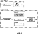
- Figure 2 shows a simplified block diagram of MUST receiver processing for a case with two superposed UEs. Since the two UEs are allocated different power levels, the near UE can attempt to cancel the interference emanating from the data transmission intended to the far UE.
- the far UE uses a normal receiver and need not even be aware that there is a superposed transmission to a near UE.
- the interference cancellation for the near UE can be done in two ways.
- a first option is that the codeword corresponding to the far UE is decoded at the near UE and then reconstructed and cancelled or removed from the received signal. This type of cancellation is referred to as codeword level interference cancellation, CWIC, in Figure 2 .
- a second option is that the near UE makes a symbol-wise hard demodulation decision of the symbols corresponding to the far UE and then cancels the interference. In Figure 2 , this type of interference cancellation is referred to as symbol level interference cancellation, SLIC.
- the near UE then decodes its own codeword(s).
- the near UE collects its own coded bits (i.e., discards the far UE coded bits) and then proceeds towards decoding its own codeword(s).
- the far UE Given that the far UE is allocated a higher transmit power level than the near UE, the far UE demodulates and decodes its own codeword without cancelling the interference emanating from the data transmission intended to the near UE.
- Non-Orthogonal Multiple Access (NOMA)
- the information bits corresponding to the far UE and the near UE are independently encoded and modulated.
- x N and x F denote the coded modulation symbols of near UE and far UE, respectively.
- the symbol x N is drawn from a near UE constellation
- the symbol x F is drawn from a far UE constellation .
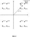
- An example of the superposed NOMA constellation for the case where both the near UE and far UE employ QPSK constellation is shown in Figure 3 . Since two QPSK constellations are used, the superposed constellation is similar to 16 QAM (depending on the value of ⁇ ).
- SOMA Semi-Orthogonal Multiple Access
- SOMA differs from the NOMA scheme in that SOMA uses Gray mapped superposed constellation.
- the coded modulation symbols of near UE and far UE are Gray mapped and then added together as in Equation 1.
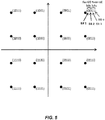
- An example of the superposed SOMA constellation for the case where both the near UE and far UE employ QPSK constellation is shown in Figure 4 .
- REMA is similar to SOMA with one restriction that the resulting superposed constellation should be a regular QAM constellation having equal horizontal and vertical spacing between constellation points (as is used in e.g. LTE).
- the bits with the higher bit-level capacities are allocated for the far UE and the bits with the lower bit-level capacities are allocated for the near UE.
- the power sharing parameter ⁇ should also be set appropriately so that the resulting superposed constellation is a regular QAM constellation.
- Table 1 There are six different ways (shown in Table 1) of realizing REMA that has LTE standard constellations as superposed constellations. Table 1.
- a transmit precoder v
- v a transmit precoder that defines how a symbol is transmitted from each of the multiple transmit antennas.
- a precoder thus contains the amplitude scaling and phase adjustment of the symbol at each of the transmit antennas. Precoding implies that beamforming gain can be achieved.
- the application of different precoders implies that the near UE has to acquire knowledge of the precoder applied to the far UE either via blind detection or explicit signalling.
- the generalized received signal model is derived for MUST schemes. It is assumed the radio access network node or eNodeB is equipped with N Tx transmit antennas and each UE has N Rx receive antennas. Assuming P to be the total transmit power per sub-carrier, let ⁇ P and (1 - ⁇ )P respectively denote the transmit powers allocated to the near UE and the far UE.
- each UE receives a rank-1 transmission stream.
- x N ( k ) and x F ( k ) denote the coded modulation symbols of near and far UEs at the k th RE, respectively.
- v ( k ) represents the N Tx -element rank-1 precoder corresponding to the transmitted stream (note that the same precoder is applied to both UEs).
- the N Rx ⁇ N Tx physical channel of the near UE is represented as H N (k)
- the near UE can try to cancel the interference component 1 ⁇ ⁇ P g N k x F k , since ⁇ ⁇ 0.5.
- the near UE can use either the CWIC or the SLIC receiver for this interference cancelation as shown in Figure 2 . Due to the regular QAM structure of REMA's superposed constellation, the near UE in the REMA case can simply use its own coded bits to decode its own codeword (see Figure 2 ).
- the N Rx ⁇ N Tx physical channel of the far UE is represented as H F ( k )
- the far UE does not cancel the interference component ⁇ P g F k x N k owing to the fact that ⁇ ⁇ 0.5.
- the far UE's total interference and noise term is given by ⁇ P g F k x N k + w F k .
- the far UE receiver processing is depicted in Figure 2 .
- the existing implicit channel state information, CSI, with a single CQI report per UE is used in MUST scheduling.
- OFDMA Orthogonal Frequency-Division Multiple Access
- SU-MIMO Single-User-Multiple Input Multiple Output
- MU-MIMO Multi-User-Multiple Input Multiple Output
- each UE within a cell reports a single channel quality information, CQI, assuming full transmission power is allocated to that UE during data transmission.
- CQI channel quality information
- the single CQI report from each UE assumes OMA operation.
- 3GPP draft R1-153332 "Evaluation methodologies for downlink multiuser superposition transmissions" relates to transmission power allocation and multi-user scheduling methodologies for NOMA.
- US 2011/032839 A1 discloses single user and multiuser MIMO transmission in a cellular network where a base station (eNB) transmits either one, two or more transmission layers and where a user equipment (UE) provides feedback to the eNB comprising one or more feedback CQI.
- eNB base station
- UE user equipment
- the existing approach Another related problem with the existing approach is the issue of CQI mismatch whenever there is rank mismatch between the OMA mode and the MUST mode.
- the MUST scheduling SINRs for the near UE is derived via the simple scaling operation of Equation 10 using the reported OMA CQI. Assuming ideal interference cancellation at the near UE, such scaling is accurate only if there is no rank mismatch between the OMA mode and the MUST mode.
- Equation 10 if there is a rank mismatch between the OMA and MUST mode, using the approach in Equation 10 will result in a CQI mismatch.
- the OMA mode has a rank of two and the MUST mode has a rank of one.
- the existing approach will result in a CQI mismatch because the rank-2 CQI report (obtained from the single OMA CQI) takes into account inter-layer interference and this is not compensated for in the simple scaling operation of Equation 10.
- a third problem with the existing scheme is that whenever there is rank mismatch between the OMA mode and the MUST mode, there will also likely be PMI mismatch. This could result in missed MUST pairing opportunities for MUST schemes that apply the same precoder to both the near and far UEs.
- various embodiments are provided for allowing multiple CSI reports to be sent by the UE for the purpose of MUST.
- the multiple CSI reports may correspond to different data transmission power levels, different rank restrictions, or different precoders with the best and the second best measured quality CQI values.
- the embodiments describe different ways of using the multiple CQI reports to identify valid MUST UE pairs.
- a method in a radio access network node configured to support the transmission of multi-user superposition transmissions, where multi-user superposition transmission comprises transmitting, in each of a plurality of time-frequency resource elements, a modulation symbol intended for a first user equipment, UE, and a modulation symbol intended for a second UE, using the same antennas and the same antenna precoding, includes receiving multiple channel-state information, CSI, reports from the first UE for a first reporting instance. One or more of the received multiple CSI reports correspond to one or more respective multi-user superposition transmission states. The method also includes determining whether to use multi-user superposition transmission or an orthogonal multiple access transmission for scheduling the first UE in a first scheduling interval, based on the received multiple CSI reports.
- a method in a first UE configured to support the transmission of multi-user superposition transmissions, where multi-user superposition transmission comprises transmitting, in each of a plurality of time-frequency resource elements, a modulation symbol intended for the first UE and a modulation symbol intended for a second UE, using the same antennas and the same antenna precoding, includes sending multiple CSI reports for a first reporting instance.
- One or more of the received multiple CSI reports correspond to one or more respective multi-user superposition transmission states.
- a method is performed by a radio access network node configured to support the transmission of multi-user superposition transmissions, where multi-user superposition transmission comprises transmitting, in each of a plurality of time-frequency resource elements, a modulation symbol intended for a first UE and a modulation symbol intended for a second UE, using the same antennas and the same antenna precoding.
- This method comprises receiving a CSI report from the first UE, the received CSI report being based on an assumption that a transmission power for a physical channel is lower than a minimum transmission power that is assumed when multi-user superposition transmission is not used.
- the method further comprises transmitting a multi-user superposition transmission to the UE, where said transmitting is based on the received CSI report.
- a method is performed in a UE configured to support the transmission of multi-user superposition transmissions, again where multi-user superposition transmission comprises transmitting, in each of a plurality of time-frequency resource elements, a modulation symbol intended for the first UE and a modulation symbol intended for a second UE, using the same antennas and the same antenna precoding.
- This method comprises receiving one or more configuration messages from a radio access network node, the one or more configuration messages directing the UE to transmit a CSI report, the one or more configuration messages comprising at least one of (a) a selected parameter indicating a ratio of a Physical Downlink Shared Channel (PDSCH) energy per resource element to a CSI reference symbol (CSI-RS) energy per resource element, wherein the selected parameter is selected from a range having a minimum value corresponding to a ratio below -8 dB, or (b) a selected parameter indicating a ratio of a PDSCH energy per resource element to a cell-specific reference symbol (CRS) energy per resource element, wherein the selected parameter is selected from an extended range having a minimum value corresponding to a ratio below -6 dB.
- PDSCH Physical Downlink Shared Channel
- CSI-RS CSI reference symbol
- the method further includes transmitting a CSI report, in accordance with the one or more configuration messages, and receiving a multi-user superposition transmission from the radio access network node.
- Still other embodiments include a radio access network node configured to support the transmission of multi-user superposition transmissions, where the radio access network node comprises a transceiver circuit configured to send and receive transmissions; a receiving module for receiving a CSI report from the first UE, the received CSI report being based on an assumption that a transmission power for a physical channel is lower than a minimum transmission power that is assumed when multi-user superposition transmission is not used, where the transceiver circuit is configured to transmit a multi-user superposition transmission to the UE, based on the received CSI report.
- a UE configured to support the transmission of multi-user superposition transmissions
- the UE comprising a transceiver circuit configured to send and receive transmissions, including a configured to receive a multi-user superposition transmission from a radio access network node, and a receiving module for receiving one or more configuration messages from the radio access network node, the one or more configuration messages directing the UE to transmit a CSI report, the one or more configuration messages comprising at least one of (a) a selected parameter indicating a ratio of a PDSCH energy per resource element to a CSI-RS energy per resource element, wherein the selected parameter is selected from a range having a minimum value corresponding to a ratio below -8 dB, or (b) a selected parameter indicating a ratio of a PDSCH energy per resource element to a CRS energy per resource element, where the selected parameter is selected from an extended range having a minimum value corresponding to a ratio below -6 dB.
- the UE further comprises a sending module for sending,
- a radio access network node is configured to support the transmission of multi-user superposition transmissions, where multi-user superposition transmission comprises transmitting, in each of a plurality of time-frequency resource elements, a modulation symbol intended for a first UE and a modulation symbol intended for a second UE, using the same antennas and the same antenna precoding.
- the radio access network node includes a transceiver circuit configured to send and receive transmissions, and a processing circuit.
- the processing circuit is configured to receive, via the transceiver circuit, multiple CSI reports from the first UE for a first reporting instance. One or more of the received multiple CSI reports correspond to one or more respective multi-user superposition transmission states.
- the processing circuit is configured to determine whether to use multi-user superposition transmission or an orthogonal multiple access transmission for scheduling the first UE in a first scheduling interval, based on the received multiple CSI reports.
- a first UE is configured to support the transmission of multi-user superposition transmissions, where multi-user superposition transmission comprises transmitting, in each of a plurality of time-frequency resource elements, a modulation symbol intended for the first UE and a modulation symbol intended for a second UE, using the same antennas and the same antenna precoding.
- the UE includes a transceiver circuit configured to send and receive transmissions, and a processing circuit.
- the processing circuit is configured to send, via the transceiver circuit, multiple CSI reports for a first reporting instance. One or more of the received multiple CSI reports correspond to one or more respective multi-user superposition transmission states.
- computer readable storage medium and computer programs may be executed on processing circuitry to perform one or more of the above methods.
- Embodiments of the present invention provide for allowing multiple CSI reports to be sent by the UE for the purpose of MUST.
- the multiple CSI reports may correspond to different data transmission power levels, different rank restrictions, or different precoders with the best and the second best measured quality CQI values.
- a radio access network node such as an LTE eNodeB, or eNB, is configured to support the transmission of multi-user superposition transmissions, where multi-user superposition transmission comprises transmitting, in each of a plurality of time-frequency resource elements, a modulation symbol intended for a first UE and a modulation symbol intended for a second UE, using the same antennas and the same antenna precoding.
- the radio access network node receives multiple CSI reports from the first UE for a first reporting instance.
- One or more of the received multiple CSI reports correspond to different possible multi-user superposition transmission states, where a multi-user superposition transmission state is a particular combination of allocated transmission power and transmit antenna precoding.
- the different possible multi-user superposition transmission states may foe example be one or more respective multi-user superposition transmission states corresponding to the one or more of the received multiple CSI reports.
- the radio access network node is also configured to determine whether to use multi-user superposition transmission or orthogonal multiple access transmission for scheduling the first UE in a first scheduling interval, based on the received multiple CSI reports.
- Reporting instances can be considered to be associated with one another, in that they generally correspond to the same interval of time and/or the same radio channel measurements.
- Reporting instances may be periodic, according to configuration instructions provided to the UE, but in some embodiments may also or instead be aperiodic, in response to a request from the radio access network node or another node.
- Example methods of receiving multiple CSI reports include where the precoding matrix indicators, PMIs, of the multiple CSI reports from one UE that correspond to different data transmission power levels, different rank restrictions, or different qualities are compared to a PMI of another CSI report from another UE for the purpose of identifying valid MUST UE pairs.
- the first UE can be configured to send CSIs when the UE is configured to receive multi-user superposition transmissions.
- This can include, for example, providing a power ratio value selected from a first set of power ratio values, where the first set of power ratio values contains smaller power ratios than a second set of power ratio values, and where the second set of power ratio values may be used for UEs that are not configured to receive multi-user superposition transmissions, and where the power ratios are ratios of PDSCH energy to reference signal energy.
- Physical Downlink Shared Channel, PDSCH can be extended to a reference signal energy per resource element, RS EPRE, ratio range in CSI reports.
- the first UE can be configured to report multiple CSIs when the UE is configured to receive multi-user superposition transmissions, where multi-user superposition transmission comprises transmitting a modulation symbol intended for a second UE using the same precoding and on the same antennas as a modulation symbol intended for the UE.
- multi-user superposition transmission comprises transmitting a modulation symbol intended for a second UE using the same precoding and on the same antennas as a modulation symbol intended for the UE.
- a plurality of parameters corresponding to different potential multi-user superposition transmission states can be provided, the plurality of parameters comprising a set of transmission powers, a set of transmission rank restrictions, and/or a set of precoder restrictions.
- one of the CSI reports is not specific to MUST, perhaps to support dynamic switching between MUST and non-MUST transmissions.
- the UE may not receive an explicit configuration message specific to MUST.
- the existing signaling, not specific to MUST can be used to realize rank restricted multiple CSI reports.
- superposition hypotheses may only include serving PDSCH parameters, where superposition is defined as using the same precoding. All of the parameters may indicate one or more potential states of a transmission intended for the UE.
- the UE is configured to send the multiple CSI reports aperiodically when requested by the eNodeB. Each CSI report may correspond to different data transmission power levels.
- Additional examples include methods where one of the CSI reports corresponds to full data transmission power level (this corresponds to OMA CQI, which is important for dynamic switching between OMA and MUST).
- the UE may assume ideal interference cancellation for the CSI reports corresponding to non-full data transmission power levels.
- Each CSI report may correspond to different rank restrictions or CSI measurements of different quality.
- Methods may include indicating a configuration of multiple CSI reports to a UE for the purposes of MUST where each configuration indication may contain one or more of a power ratio parameter with extended range to support MUST (radio resource control, RRC, signaling), a list of power ratio parameters with extended range to support MUST (RRC signaling), and/or a bit string indicating the restricted set of precoders to be considered during CSI measurements and feedback.
- MUST radio resource control
- RRC signaling radio resource control, RRC signaling
- RRC signaling resource control parameters with extended range to support MUST
- bit string indicating the restricted set of precoders to be considered during CSI measurements and feedback.
- a signal corresponding to the interference from a first UE to a second UE is transmitted on the interference measurement resource of the second UE where the first UE is configured to receive multi-user superposition transmissions.
- the interference component is transmitted using the same precoding and on the same antennas as the modulation symbols intended for the first and second UEs.
- multi-user superposition is distinct from multi-user multiple-input and multiple-output, MIMO, as used in LTE in that for multi-user superposition transmissions, the same antenna patterns and precoding (or "same effective antenna") are used for the transmissions intended for the different UEs.
- Multi-user MIMO relies on spatial multiplexing between the users, which is achieved by using different antennas and/or antenna precoding. To facilitate multi-user superposition transmissions, the CSI feedback should accurately predict the needed transmission parameters to obtain good downlink throughput given this same effective antenna behavior.
- CSI feedback comprises at least channel quality information, CQI, indicating a modulation and coding rate that could be used for a PDSCH transmitted to the UE providing the feedback at a predetermined block error rate.
- CQI channel quality information
- a CSI report may also comprise additional feedback such as precoding matrix indications, rank indications, etc. Therefore, in some cases, a UE is configured to send multiple CSI reports for the purpose of multi-user superposition transmission.
- the CSI reports may comprise at least a channel quality indication.
- a plurality of parameters corresponding to different potential multi-user superposition transmission states are hypothesized in CSI feedback.
- the amount of feedback overhead and UE computational complexity grows in proportion to the number of parameters and multi-user transmission states for which the UE provides CSI feedback. Therefore, it is generally desirable to provide a small number of parameters that provides as much performance gain as possible.
- N parameter settings are jointly and independently hypothesized for M users in a multi-user transmission
- the number of parameter settings is on the order of N M .
- One approach to avoiding this exponential growth of the number of parameter hypotheses is to provide parameters corresponding only to hypotheses of the PDSCH intended for the UE, rather than those for both the intended and interfering PDSCHs, and to have the UE assume that single user transmission is used. In this case, it is still possible to have accurate CSI feedback when an interfering PDSCH is transmitted, so long as it is transmitted in the same way (i.e., using the precoding, etc.) as the desired PDSCH. This allows dynamic switching between multi-user superposition and single-user transmission.
- the UE should calculate the CSI assuming that a superposed far UE PDSCH does not interfere with the received near UE PDSCH. Therefore, in some embodiments, when calculating the MUST specific CQIs, a UE that employs interference cancellation (i.e., a 'near' UE, UE 1 ) may assume that the interference component in Equation 6 can be completely cancelled.
- an eNodeB generally configures the UE(s) to send multiple CSI reports where one of the CSI reports corresponds to the OMA mode and one or more other CSI reports correspond to the MUST mode. Having one CSI report for OMA and one or more CSI report(s) for MUST ensures that the proposed solution supports dynamic switching between OMA and MUST modes. That is, the scheduler in the proposed scheme can more accurately decide whether OMA or MUST should be employed in a given scheduling band depending on which scheme provides the highest PF rate.
- the eNodeB may configure only the near UE(s) to send multiple CSI reports for the purposes of MUST; the far UE(s) may be configured to send only a single OMA CSI report.
- the eNodeB may use Reference Signal Received Power, RSRP, reports and/or uplink pathloss measurements to distinguish between the near and far UEs.
- the eNodeB configures the OMA CSI report such that full transmission power allocation is assumed when the UE measures CQI.
- the eNodeB configures the UE(s) such that each of the MUST specific CQIs corresponds to a different power share value.
- Step 1 The eNodeB configures a near UE UE 1 to send Q > 1 CSI reports.
- One of the reports contains a CQI denoted by CQI UE 1 0 that corresponds to the OMA CQI (i.e., assumes full transmission power).
- the remaining Q - 1 CSI reports contain CQIs denoted by CQI UE 1 1 , CQI UE 1 2 , ... , CQI UE 1 Q ⁇ 1 that respectively correspond to Q - 1 different MUST power share values ⁇ 1 , ⁇ 2 , ..., ⁇ Q- 1 (note that ⁇ 1 , ⁇ 2 , ..., ⁇ Q- 1 are assumed to be in non-decreasing order here).
- the eNodeB configures a far UE UE 2 to send a single OMA CSI report containing a CQI that is denoted by CQI UE 2 0 .
- Step 2 UE 1 calculates the CSI reports (including the CQIs) according to the power share hypotheses, and then sends the Q CSI reports to the eNodeB. Similarly, UE 2 sends the OMA CSI report to the eNodeB. When calculating the MUST specific CSIs, UE 1 may assume that the interference component in Equation 6 can be completely cancelled.
- Step 3 For each scheduling band, the eNodeB scheduler first checks if CQI UE 1 0 is sufficiently higher than CQI UE 2 0 . Additionally, the scheduler checks the combination of precoders among these UEs when deciding whether UE 1 and UE 2 can be valid MUST pairs. This is done by comparing the PMI corresponding to CQI UE 2 0 with the PMIs corresponding to CQI UE 1 1 , CQI UE 1 2 , ... , CQI UE 1 Q ⁇ 1 .
- Step 4 If UE 1 and UE 2 are deemed a valid MUST pair, then the eNodeB scheduler can select a near UE power share parameter ⁇ close to ⁇ q .
- the parameter ⁇ is selected from a set A of predetermined power share parameter values (i.e., ⁇ ⁇ A ) .
- Step 5 For the selected ⁇ value, calculate the scheduling SINRs for MUST using SINR UE 1 and SINR UE 2 , corresponding to CQI reports CQI UE 1 q and CQI UE 2 q with the following approximations:
- Step 6 The scheduler then calculates the MUST PF metric corresponding to the MUST UE pair under consideration as ⁇ UE i ⁇ U R i
- U , ⁇ , ⁇ q ) is a function of MUST scheduling SINRs computed in Equation 13-Equation 14, and hence R(i
- the candidate user set U contains the MUST UE pair under consideration.
- Step 7 The steps 3-6 are repeated for all valid MUST UE pairs with all ⁇ q that yield matching PMIs and all ⁇ values in the set A. Additionally, the OMA PF metrics corresponding to each UE belonging to the serving cell are also calculated using the reported OMA CQIs (i.e., CQI UE 1 0 and CQI UE 2 0 ) as is currently done in LTE.
- Step 8 From Step 7, the scheduler decides whether OMA or MUST should be employed in the current scheduling band depending on which scheme provides the highest PF rate.
- the UE(s) corresponding to the highest PF metric are scheduled.
- the power share parameter pair ( ⁇ , ⁇ q ) that yields the highest PF rate is chosen.
- the eNodeB in Step 1, may configure a far UE UE 2 using LTE transmission mode 10 to send a single CSI report containing a CQI while at the same time transmitting the interference term ⁇ P g F k x N k (see Equation 9) in UE 2 's interference measurement resource (IMR).
- the far UE UE 2 may not be aware of the superposed interference from UE 1 and may not be configured to receive multi-user superposition transmission. Since transmitting the interference term on the IMR improves a UE's interference estimate without requiring any a-priori knowledge of the interference characteristics, the CSI feedback from a far UE served by multi-user superposition transmission can be improved without any additional UE complexity.
- the far UE may not need to be aware that its power share value of (1 - ⁇ ) is for the purpose of MUST transmission.
- MUST specific CSI i.e., CQI UE 1 q
- CQI UE 1 q MUST specific CSI
- Step 3 calculating near UE's MUST scheduling SINR
- Step 5 calculating near UE's MUST scheduling SINR
- Step 6 MUST PF metrics
- the solution of Embodiment 1 also supports dynamic switching between OMA and MUST modes. That is, the scheduler in the proposed scheme can more accurately decide whether OMA or MUST should be employed in a given scheduling band depending on which scheme provides the highest PF rate.
- a parameter P c is signaled by the eNodeB to the UE to indicate the ratio of the PDSCH energy per resource element ('EPRE') to CSI-RS EPRE.
- the P c parameter indicates the ratio of the downlink data transmitted power per resource element to the channel state information reference symbol power per resource element.
- the UE uses the P c parameter to determine the reference data transmission power during CSI feedback.
- P c takes values in the range of [-8, 15] dB with 1 dB step size.
- the range of P c should be extended to cover the desired near UE power share ⁇ values in dB.
- the range of near UE power share values in Table 1 should be covered. So if the range of P c is extended to [-19, 15] dB then all the possible REMA cases in Table 1 should be covered. However, if extending the range of P c value to -19 dB is an overkill, then a more reasonable range extension for P c would be [-13, 15] dB which covers a majority of superposed REMA constellations in Table 1.
- p-C-r11 An example using RRC signaling of the CSI-Process information element with the range-extended P c parameter (which is denoted as p-C-r11 ) is shown in Table 2.
- subframe patterns for CSI (CQI/PMI/PTI/RI) reporting are configured (i.e. csi-SubframePatternConfig is configured)
- the UE can be configured to send two CSI reports per CSI process in the two CSI measurement subframe sets currently supported in LTE.
- the eNodeB it is possible for the eNodeB to configure a near UE to report up to 5 MUST specific CSIs and 1 OMA CSI.
- CSI-Process information element This sequence will contain a configurable number (for instance, say Q ) of entries of type P c .
- the eNodeB will configure the UE to report Q CSI measurements from the same CSI process (thus, reducing the CSI-RS overhead from having to use multiple CSI processes).
- Each of the Q CSI reports will correspond to one of P c values contained in p-C-List.
- Embodiment 1 can be realized in LTE TM10 with a flexibly configurable number Q of CSI reports.
- CSI-Process field descriptions are as follows.
- EUTRAN may configure the field only if the number of CSI-RS ports for non-zero power transmission CSI-RS configuration is 4.
- csi-MeasSubframeSets-r12 is configured for the same frequency as the CSI process, cqi-ReportAperiodicProc applies for CSI subframe set 1. If csi-MeasSubframeSet1-r10 or csi-MeasSubframeSet2-r10 are configured for the same frequency as the CSI process, cqi-ReportAperiodicProc applies for CSI subframe set 1 or CSI subframe set 2. Otherwise, cqi-ReportAperiodicProc applies for all subframes
- cqi-ReportAperiodicProc2 is configured only if csi-MeasSubframeSets-r12 is configured for the same frequency as the CSI process. cqi-ReportAperiodicProc2 is for CSI subframe set 2. E-UTRAN shall set cqi-ReportModeAperiodic-r11 in cqi-ReportAperiodicProc2 the same as in cqi-ReportAperiodicProc.
- E-UTRAN configures the field if and only if cqi-ReportPeriodicProcId is included and/ or if cqi-ReportAperiodicProc is included.
- Value 0 refers to the set of parameters defined by the REL-10 CQI reporting configuration fields, while the other values refer to the additional configurations E-UTRAN assigns by CQI-ReportPeriodicProcExt-r11 (and as covered by CQI-ReportPeriodicProcExtId ) .
- csi-IM-ConfigIdList can include 2 entries only if csi-MeasSubframeSets-r12 is configured for the same frequency as the CSI process.
- UE shall ignore csi-IM-ConfigId-r11 if csi-IM-ConfigldList-r12 is configured.
- a p-C-AndCBSRList including 2 entries indicates that the subframe patterns configured for CSI (CQI/PMI/PTI/RI) reporting (i.e. as defined by field csi-MeasSubframeSet1 and csi-MeasSubframeSet2 , or as defined by csi-MeasSubframeSets-r12 ) are to be used for this CSI process, while a single entry indicates that the subframe patterns are not to be used for this CSI process.
- E-UTRAN does not include 2 entries in p-C-AndCBSRList with csi-MeasSubframeSet1 and csi-MeasSubframeSet2 for CSI processes concerning a secondary frequency.
- E-UTRAN includes 2 entries in p-C-AndCBSRList when configuring both cqi-pmi-Configlndex and cqi-pmi-ConfigIndex2.
- the RRC signaling required to support the solution of Embodiment 1 in LTE transmission mode 9, TM9, can be realized in a few different ways.
- An example RRC signaling of the CSI-RS-Config information element is shown in Table.
- a new optional integer p-C2 is introduced in the CSI-RS-Config information element with range [-13, 15] dB which covers a majority of the superposed REMA constellations in Table 1. If subframe patterns for CSI (CQI/PMI/PTI/RI) reporting are configured (i.e.
- the existing integer p-C-r10 is only used in the first CSI-MeasSubframeSet (i.e., CSI-MeasSubframeSet1 ) and the newly introduced integer p-C2 is only used in the second CSI-MeasSubframeSet (i.e., CSI-MeasSubframeSet2 ) .
- the eNodeB can configure a near UE in TM9 to send one OMA CSI report on the first CSI-MeasSubframeSet and one MUST CSI report on the second CSI-MeasSubframeSet.
- An alternative RRC signaling approach is to introduce a new sequence called p-C-List in the CSI-RS-Config information element.
- This sequence will contain a configurable number (for instance, say Q ) of entries of type P c .
- the range of values for P c will be extended to cover the MUST near UE power share values of interest (for instance, this range can be set to [-13, 15] dB as discussed above).
- the eNodeB will configure the UE to report Q CSI measurements per CSI-RS-Config.
- Each of the Q CSI reports will correspond to one of P c values contained in p-C-List.
- Embodiment 1 can be realized in LTE TM9 with a flexibly configurable number Q of CSI reports.
- CSI-RS-Config field descriptions will be provided.
- Parameter for additional zeroTxPowerCSI-RS for a serving cell concerning the CSI-RS included in discovery signals.
- E-UTRAN configures the field only if csi-MeasSubframeSets-r12 and TM 1 - 9 are configured for the serving cell.
- Additional P c parameter only signalled when subframe patterns for CSI (CQI/PMI/PTI/RI) reporting are configured and when multiple CQI reports for the purposes of MUST are desired. If signalled, p-C is only used in the first CSI-MeasSubframeSet (i.e., CSI-MeasSubframeSet1 ) and p-C2 is only used in the second CSI-MeasSubframeSet (i.e., CSI-MeasSubftameSet2 ).
- I CSI-RS see TS 36.211 (See Tables 6.10.5.3-1).
- I CSI-RS see TS 36.211 (See Table 6.10.5.3-1).
- TM4 The RRC signaling required to support the solution of Embodiment 1 in LTE transmission mode 4, TM4, can be realized in a few different ways.
- a parameter P A is signaled by the eNodeB to the UE which is used to define the ratio of the PDSCH EPRE to cell specific RS ('CRS') EPRE.
- the UE uses the P A parameter to determine the reference data transmission power during CSI feedback.
- P A can take on values of ⁇ -6 dB, -4.77 dB, -3 dB, -1.77 dB, 0 dB , 1 dB , 2 dB, 3 dB ⁇ .
- the range of P A should be extended to cover the desired near UE power share ⁇ values in dB.
- the range of near UE power share values in Table 1 should be covered. So if additional values of -19.21 dB, -13.19 dB, -12.29 dB, and -6.9867 dB can be added to the list of possible P A values then all the possible REMA cases in Table 1 should be covered. If this is overkill, a subset of these additional values can be added to the list of possible P A values so that most of the superposed REMA constellations in Table 1 can be supported.
- One alternative is to define a new information element, IE, called MUST-AssistanceInfo as shown in Table 4.
- This new IE will be part of the dedicated RRC signaling.
- the IE contains a sequence servCellp-aList of size maxP-a-PerServCell-r13 (containing P A values) to be signaled when multiple CSI reports for the purposes of MUST are desired.
- the eNodeB will configure the UE to report Q CSI measurements where Q is equal to maxP-a-PerServCell-r13.
- Each of the Q CQIs in the CSI reports will correspond to one of P A values contained in servCellp-aList.
- Embodiment 1 can be realized in LTE TM4 with a flexibly configurable number Q of CSI reports.
- the size of servCellp-aList in Table 4 can be set to 2. If subframe patterns for CSI (CQI/PMI/PTI/RI) reporting are configured (i.e. csi-SubframePatternConfig is configured), then the first P A value in servCellp-aList is only used in the first CSI-MeasSubframeSet (i.e., CSI-MeasSubframeSet1 ) and the second P A value in servCellp-aList is only used in the second CSI-MeasSubframeSet (i.e., CSI-MeasSubframeSet2 ) .
- MUST-AssistanceInfo field descriptions are defined as the following.
- the eNodeB may configure only the near UE(s) to send multiple CQI reports for the purposes of MUST; the far UE(s) may be configured to send only a single OMA CSI report.
- the eNodeB may use RSRP reports and/or uplink pathloss measurements to distinguish between the near and far UEs.
- Step 1 The eNodeB configures a near UE UE 1 to send R max > 1 CSI reports.
- the r th CSI report with CQI UE 1 r of UE 1 is restricted to rank r where 1 ⁇ r ⁇ R max .
- the eNodeB configures a far UE UE 2 to send a single OMA CSI report that contains a CQI denoted by CQI UE 2 .
- Step 2 UE 1 sends the R max CSI reports to the eNodeB. Similarly, UE 2 sends the OMA CSI report to the eNodeB. When measuring the R max CSIs, UE 1 will assume full data transmission power is allocated to itself.
- Step 3 For each scheduling band, the eNodeB scheduler first determines the OMA CSI (containing a CQI denoted by CQI UE 1 ) corresponding to UE 1 . This is done by choosing the CQI from the CSI reports that provides the best instantaneous throughput among CQI UE 1 1 , CQI UE 1 2 , ... , CQI UE 1 R max .
- Step 4 For each scheduling band, the eNodeB scheduler checks if CQI UE 1 is sufficiently higher than CQI UE 2 . Additionally, the scheduler checks the combination of precoders among these UEs when deciding whether UE 1 and UE 2 can be valid MUST pairs. This is done by comparing the PMI corresponding to CQI UE 2 with the PMIs corresponding to CQI UE 1 1 , CQI UE 1 2 , ... , CQI UE 1 R max . If the PMI of CQI UE 2 matches the PMI of CQI UE 1 r where 1 ⁇ r ⁇ R max , then UE 1 and UE 2 can be valid MUST pairs.
- Step 5 If UE 1 and UE 2 are deemed a valid MUST pair, then the eNodeB scheduler can select a near UE power share parameter ⁇ .
- the parameter ⁇ is selected from a set A of predetermined power share parameter values (i.e., ⁇ ⁇ A ) .
- Step 6 For the selected ⁇ value, calculate the scheduling SINRs for MUST using SINR UE 1 and SINR UE 2 , corresponding to CQI reports CQI UE 1 r and CQI UE 2 with the following approximations:
- Step 7 The scheduler then calculates the MUST PF metric corresponding to the MUST UE pair under consideration as ⁇ UE i ⁇ U R i
- U , ⁇ ) is a function of MUST scheduling SINRs computed in Equation 17-Equation 18, and hence R(i
- the candidate user set U contains the MUST UE pair under consideration.
- Step 8 The steps 3-7 are repeated for all valid MUST UE pairs with all rank (i.e., all r) values that yield matching PMIs and all ⁇ values in the set A. Additionally, the OMA PF metrics corresponding to each UE belonging to the serving cell are also calculated using the reported OMA CQIs (i.e., CQI UE 1 and CQI UE2 ) as is currently done in LTE.
- Step 9 From Step 8, the scheduler decides whether OMA or MUST should be employed in the current scheduling band depending on which scheme provides the highest PF rate.
- the UE(s) corresponding to the highest PF metric are scheduled.
- the MUST scheme is scheduled in the scheduling band, the power share parameter ⁇ and the rank value r that yield the highest PF rate are chosen.
- Embodiment 2 also supports dynamic switching between OMA and MUST modes. That is, the scheduler in the proposed scheme can more accurately decide whether OMA or MUST should be employed in a given scheduling band depending on which scheme provides the highest PF rate. If very high ranks are unlikely due to the channel conditions, this embodiment can also be used with a rank R ⁇ R max .
- the RRC signaling required to support the solution of Embodiment 2 in LTE TM10 can be realized in a few different ways.
- a parameter codebookSubsetRestriction is signaled by the eNodeB to the UE to indicate the restricted set of precoders to be considered during CSI measurements/feedback.
- the eNodeB could use this parameter to implement different rank restrictions of Embodiment 2 on different CSI reports.
- the existing RRC signaling of the CSI-Process information element is shown in Table 5.
- subframe patterns for CSI (CQI/PMI/PTI/RI) reporting are configured (i.e. csi-SubframePatternConfig is configured)
- the UE can be configured to send two CSI reports per CSI process in the two CSI measurement subframe sets currently supported in LTE.
- PTI stands for precoding type indicator.
- R max 6 CSI reports in LTE TM10 (i.e., 2 CQI reports per CSI process ⁇ 3 CSI processes).
- CBSR-List in the CSI-Process information element.
- This sequence will contain a configurable number (for instance, say R max ) of entries of type codebookSubsetRestriction.
- the eNodeB will configure the UE to report R max CSI measurements from the same CSI process (thus, reducing the CSI-RS overhead from having to use multiple CSI processes).
- Each of the R max CSI reports will correspond to a different rank restriction indicated by one of the codebookSubsetRestriction bit strings contained in CBSR-List.
- Embodiment 2 can be realized in LTE TM10 with a flexibly configurable number R max of CSI reports.
- the RRC signaling required to support the solution of Embodiment 2 in LTE TM4 and TM9 can be realized in a few different ways.
- One alternative is to define a new IE called MUST-Assistancelnfo as shown in Table 6. This new IE will be part of the dedicated RRC signaling.
- the IE contains a sequence CBSRList of size maxCBSR-r13 (containing codebookSubsetRestriction values) to be signaled when multiple CSI reports for the purposes of MUST are desired.
- the eNodeB will configure the UE to report R max CSI measurements where R max is equal to maxCBSR-r13.
- Embodiment 2 can be realized in LTE TM4 and TM9 with a flexibly configurable number R max of CSI reports.
- the size of CBSRList in Table 6 can be set to 2. If subframe patterns for CSI (CQI/PMI/PTI/RI) reporting are configured (i.e. csi-SubframePatternConfig is configured), then the rank restriction indicated by the first codebookSubsetRestriction bit string in CBSRList is only used in the first CSI-MeasSubframeSet (i.e., CSI-MeasSubframeSet1 ) and the rank restriction indicated by the second codebookSubsetRestriction bit string in CBSRList is only used in the second CSI-MeasSubframeSet (i.e., CSI-MeasSubframeSet2 ) .
- MUST-AssistanceInfo field descriptions are described as follows.
- codebookSubsetRestriction see TS 36.213 (see Section 7.2) and TS 36.211 (see Section 6.3.4.2.3).
- the number of bits in the codebookSubsetRestriction for applicable transmission modes is defined in TS 36.213 (see Table 7.2-1b).
- E-UTRAN configures the field codebookSubsetRestriction if PMI/RI reporting is configured.
- transmissionMode tm9 E-UTRAN configures the field codebookSubsetRestriction if PMI/RI reporting is configured and if the number of CSI-RS ports is greater than 1.
- E-UTRAN does not configure the field codebookSubsetRestriction in other cases where the UE is configured with transmissionMode tm8 or tm9.
- the UE may be desirable to configure the UE so that it provides a mixed-rank CSI in addition to one or more rank-restricted CSIs, particularly when the maximum supportable rank is high. For instance, if there are there three CSI processes and up to four ranks, then the UE might be configured, using the above techniques, to report a rank-1 CSI for the first CSI process, a rank-2 CSI for the second CSI process, and a joint rank3-rank4 restriction on the third process (meaning that the third CSI process can consider both rank-3 and rank-4). This way embodiment 2 can be supported for higher rank cases without increasing the number of CSI processes.
- the eNodeB configures the UE(s) to send Z > 1 CSI reports for the purposes of MUST wherein the z th CSI report contains the z th best CQI (the corresponding PMI and RI are also included in the report).
- the UE will assume full data transmission power is allocated to the UE during CSI measurement corresponding to all CSI reports.
- the eNodeB may configure only the near UE(s) to send multiple CSI reports for the purposes of MUST; the far UE(s) may be configured to send only a single OMA CSI report.
- the eNodeB may use RSRP reports and/or uplink pathloss measurements to distinguish between the near and far UEs.
- the steps involved in this embodiment are summarized below. Although these steps are described using one near UE and one far UE, the solution proposed in this embodiment is applicable to a plurality of near and far UEs.
- Step 1 The eNodeB configures a near UE UE 1 to send Z > 1 CSI reports.
- One of the CQIs in the reports denoted by CQI UE 1 0 corresponds to the OMA CQI (i.e., the best CQI).
- the remaining Z - 1 CQIs in the reports are denoted by CQI UE 1 1 , CQI UE 1 2 , ... , CQI UE 1 Z ⁇ 1 , where the z th CSI report with CQI UE 1 z contains the z th best CQI.
- the eNodeB configures a far UE UE 2 to report a single OMA CSI report that contains a CQI that is denoted by CQI UE 2 0 .
- Step 2 UE 1 sends the Z CSI reports to the eNodeB. Similarly, UE 2 sends the OMA CSI report to the eNodeB. When measuring the Z CSIs, UE 1 will assume full data transmission power is allocated to itself.
- Step 3 For each scheduling band, the eNodeB scheduler first checks if CQI UE 1 0 is sufficiently higher than CQI UE 2 0 . Additionally, the scheduler checks the combination of precoders among these UEs when deciding whether UE 1 and UE 2 can be valid MUST pairs. This is done by comparing the PMI corresponding to CQI UE 2 0 with the PMIs corresponding to CQI UE 1 0 , CQI UE 1 2 , ... , CQI UE 1 Z ⁇ 1 . If the PMI of CQI UE 2 0 matches the PMI of CQI UE 1 z where 0 ⁇ z ⁇ (Z - 1), then UE 1 and UE 2 can be valid MUST pairs.
- Step 4 If UE 1 and UE 2 are deemed a valid MUST pair, then the eNodeB scheduler can select a near UE power share parameter ⁇ .
- the parameter ⁇ is selected from a set A of predetermined power share parameter values (i.e., ⁇ ⁇ A ) .
- Step 5 For the selected ⁇ value, calculate the scheduling SINRs for MUST using SINR UE 1 and SINR UE 2 , corresponding to CQI reports CQI UE 1 z and CQI UE 2 0 with the following approximations:
- Step 6 The scheduler then calculates the MUST PF metric corresponding to the MUST UE pair under consideration as ⁇ UE i ⁇ U R i
- U , ⁇ ) is a function of MUST scheduling SINRs computed in Equation 20-Equation 21, and hence R(i
- the candidate user set U contains the MUST UE pair under consideration.
- Step 7 The steps 3-6 are repeated for all valid MUST UE pairs with all possible z values that yield matching PMIs and all ⁇ values in the set A . Additionally, the OMA PF metrics corresponding to each UE belonging to the serving cell are also calculated using the reported OMA CQIs (i.e., CQI UE 1 0 and CQI UE 2 0 ) as is currently done in LTE.
- Step 8 From Step 7, the scheduler decides whether OMA or MUST should be employed in the current scheduling band depending on which scheme provides the highest PF rate.
- the UE(s) corresponding to the highest PF metric are scheduled.
- the power share parameter ⁇ and the z value that yield the highest PF rate are chosen.
- Embodiment 3 also supports dynamic switching between OMA and MUST modes. That is, the scheduler in the proposed scheme can more accurately decide whether OMA or MUST should be employed in a given scheduling band depending on which scheme provides the highest PF rate.
- Reporting multiple RI/PMI/CQIs periodically for a UE means increased uplink feedback overhead.
- One solution to reduce the feedback overhead is to only feedback/report the multiple configured RI/PMI/CQI when requested.
- a UE only reports multiple RI/PMI/CQIs when it is requested by the serving eNodeB or a network node.
- the request can be dynamically indicated to the UE by the eNodeB.
- a UE may be configured with one RI/PMI/CQI hypothesis assuming full transmit power (existing LTE CQI configuration) and with additional RI/PMI/CQI hypothesis as discussed in the previous embodiments using RRC signaling.
- a UE only report a new RI/PMI/CQI based on one of the additional hypothesis when requested by the eNodeB as shown in Figure 6 .
- the request can be triggered in a subframe by subframe basis. For example, when a potential UE pair is identified for MUST transmission, the eNodeB may send a request to the near UE for a CQI report based on a reduced transmit power to get better CQI (and/or RI) estimation for MUST transmission.
- the requests from the eNodeB may only be sent to near UEs and the feedback may be restricted to rank 1 PMI/CQI reports.
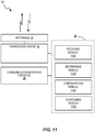
- FIG. 7 illustrates a diagram of a radio access network node 30, such as a base station or a base station operating in coordination with a base station controller, according to some embodiments.
- the radio access network node 30 includes one or more communication interface circuits 38 in order to communicate with network nodes or peer nodes.
- the radio access network node 30 provides an air interface to wireless devices, which is implemented via one or more antennas 34 and a transceiver circuit 36.
- the transceiver circuit 36 may include transmitter circuits, receiver circuits, and associated control circuits that are collectively configured to transmit and receive signals according to a radio access technology for the purposes of providing communication services.
- the radio access network node 30 can communicate with one or more peer nodes or core network nodes.
- the transceiver circuit 36 is configured to communicate using cellular communication services operated according to wireless communication standards (e.g. Global System for Mobile communication (GSM), General Packet Radio Services (GPRS), Wideband Code Division Multiple Access (WCDMA), High Speed Downlink Packet Access (HSDPA), LTE and LTE-Advanced).
- GSM Global System for Mobile communication
- GPRS General Packet Radio Services
- WCDMA Wideband Code Division Multiple Access
- HSDPA High Speed Downlink Packet Access
- LTE Long Term Evolution
- LTE-Advanced Long Term Evolution
- GSM Global System for Mobile communication
- GPRS General Packet Radio Services
- WCDMA Wideband Code Division Multiple Access
- HSDPA High Speed Downlink Packet Access
- LTE Long Term Evolution
- LTE Long Term Evolution-Advanced
- the radio access network node 30 also includes one or more processing circuits 32 that are operatively associated with the communication interface circuit(s) 38 and/or the transceiver circuit 36.
- the processing circuit 32 comprises one or more digital processors 42, e.g., one or more microprocessors, microcontrollers, Digital Signal Processors or DSPs, Field Programmable Gate Arrays or FPGAs, Complex Programmable Logic Devices or CPLDs, Application Specific Integrated Circuits or ASICs, or any combination thereof. More generally, the processing circuit 32 may comprise fixed circuitry, or programmable circuitry that is specially configured via the execution of program instructions implementing the functionality taught herein, or may comprise some combination of fixed and programmable circuitry.
- the processor(s) 42 may be multi-core.
- the processing circuit 32 also includes a memory 44.
- the memory 44 stores one or more computer programs 46 and, optionally, configuration data 48.
- the memory 44 provides non-transitory storage for the computer program 46 and it may comprise one or more types of computer-readable media, such as disk storage, solid-state memory storage, or any combination thereof.
- the memory 44 may comprise any one or more of Static Random-Access Memory (SRAM), Dynamic Random-Access Memory (DRAM), Electrically Erasable Programmable Read-Only Memory (EEPROM), and FLASH memory, which may be in the processing circuit 32 and/or separate from the processing circuit 32.
- the memory 44 comprises one or more types of computer-readable storage media providing non-transitory storage of the computer program 46 and any configuration data 48 used by the node 30.
- the radio access network node 30 is configured to support the transmission of multi-user superposition transmissions, where multi-user superposition transmission comprises transmitting, in each of a plurality of time-frequency resource elements, a modulation symbol intended for a first UE and a modulation symbol intended for a second UE, using the same antennas and the same antenna precoding.
- the processing circuit 32 is configured to receive multiple CSI reports from the first UE for a first reporting instance, wherein one or more of the received multiple CSI reports correspond to different possible multi-user superposition transmission states.
- the processing circuit 32 is configured to determine whether to use multi-user superposition transmission or an orthogonal multiple access transmission for scheduling the first UE in a first scheduling interval, based on the received multiple CSI reports.
- the processing circuit 32 is configured to perform any of the operations described in the embodiments above for the radio access network node. This functionality may be represented or carried out by scheduling circuitry 40.
- the processing circuit 32 is configured to perform operations, as described in the above embodiments.
- the processing circuit 32 is configured to perform method 800 illustrated by the flowchart in Figure 8 .
- the method 800 operates in a radio access network node 30 configured to support the transmission of multi-user superposition transmissions, where multi-user superposition transmission comprises transmitting, in each of a plurality of time-frequency resource elements, a modulation symbol intended for a first UE and a modulation symbol intended for a second UE, using the same antennas and the same antenna precoding.
- the method 800 includes receiving multiple CSI reports from the first UE for a first reporting instance, wherein one or more of the received multiple CSI reports correspond to different possible multi-user superposition transmission states (block 802).
- the method 800 also includes determining whether to use multi-user superposition transmission or an orthogonal multiple access transmission for scheduling the first UE in a first scheduling interval, based on the received multiple CSI reports (block 804).
- the first UE is sent scheduling messages or configuration messages, the configuration messages directing the first UE to provide multiple CSI reports for at least the first reporting instance.
- a first one of the received multiple CSI reports may include a CQI corresponding to a full-power or substantially full-power data transmission to the first UE. Note that "first” does not limit the embodiment or the claims to any type of order or sequence of receiving CQI reports.
- the radio access network node 30 determines whether to use multi-user superposition transmission or an orthogonal multiple access transmission. According to some embodiments, this determination is made by obtaining a CSI report from a second UE, the CSI report from the second UE comprising a CQI corresponding to a full-power or substantially full-power data transmission to the second UE, determining that multi-user superposition transmission to the first and second UEs is feasible, in that transmission to both UEs can be performed using the same antennas and antenna precoding and with a power allocation such that the signal can be successfully received and decoded by both UEs.
- This feasibility determination is made by determining that said CQI for the first UE is greater than said CQI for the second UE by a predetermined factor or threshold, and determining that a precoder matrix indicator, PMI, corresponding to the CSI report from the second UE matches at least one PMI corresponding to one of the received multiple CSI reports from the first UE other than said first one of the received multiple CSI reports.
- Obtaining the CSI report from the second UE may include transmitting, in an interference measurement resource, IMR, for the second UE, an interference component corresponding to a potential power share allocated to the first UE in a multi-user superposition transmission to the first and second UEs.
- the interference component is transmitted using the same antennas and the same antenna precoding intended for the multi-user superposition transmission to the first and second UEs.
- An antenna precoding is as a mapping of one or more signals to multiple antennas, according to precoding weights.
- Obtaining the CSI report may further include receiving, from the second UE, the CQI corresponding to a full-power or substantially full-power data transmission to the second UE, wherein said CQI reflects the interference component transmitted in the IMR for the second UE.
- the multiple CSI reports may correspond to different power-sharing hypotheses for multi-user superposition transmission to the first UE, and/or different ranks for data transmission to the first UE.
- configuration messages may indicate different power-sharing hypotheses, and/or a number of CQIs to be reported by the first UE, each CQI corresponding to a different rank for data transmission to the first UE.
- the configuration messages may signal, for each desired CSI report, a corresponding transmission rank by indicating a set of precoders that are restricted to the corresponding transmission rank. Restricted precoders can mean that a precoder is for use with only one rank.
- the UE may be desirable to configure the UE so that it provides a mixed-rank CSI in addition to one or more rank-restricted CSIs, particularly when the maximum supportable rank is high. For instance, if there are there three CSI processes and up to four ranks, then the UE might be configured, using the above techniques, to report a rank-1 CSI for the first CSI process, a rank-2 CSI for the second CSI process, and a joint rank3-rank4 restriction on the third process.
- the multiple CSI reports from the first UE may also include N CSI reports, the N CSI reports comprising the N best channel quality indicators, CQIs, and wherein each of the N CSI reports includes a corresponding precoding matrix indicator, PMI, and rank indicator, RI.
- signaling may indicate whether one or more of the CSI reports are for Coordinated MultiPoint, CoMP, transmissions and/or MUST transmissions.
- FIG. 9 illustrates a diagram of a wireless device, such as UE 50, according to some embodiments.
- the user equipment 50 may also be considered to represent any wireless devices that may operate in a network.
- the UE 50 herein can be any type of wireless device capable of communicating with a network node or another UE over radio signals.
- the UE 50 may also be radio communication device, target device, device to device- (D2D), UE, machine type UE or UE capable of machine to machine communication (M2M), a sensor equipped with UE, personal digital assistant (PDA), Tablet, mobile terminal, smart phone, laptop embedded equipped (LEE), laptop mounted equipment (LME), Universal Serial Bus (USB) dongles, Customer Premises Equipment (CPE), etc.
- D2D device to device-
- M2M machine to machine communication
- PDA personal digital assistant
- Tablet mobile terminal
- smart phone laptop embedded equipped (LEE)
- LME laptop mounted equipment
- USB Universal Serial Bus
- CPE Customer Premises Equipment
- the UE 50 communicates with a radio node or base station, such as the radio access network node 30, via antennas 54 and a transceiver circuit 56.
- the transceiver circuit 56 may include transmitter circuits, receiver circuits, and associated control circuits that are collectively configured to transmit and receive signals according to a radio access technology, for the purposes of providing cellular communication services.
- the UE 50 also includes one or more processing circuits 52 that are operatively associated with the transceiver circuit 56.
- the processing circuit 52 comprises one or more digital processing circuits, e.g., one or more microprocessors, microcontrollers, Digital Signal Processors or DSPs, Field Programmable Gate Arrays or FPGAs, Complex Programmable Logic Devices or CPLDs, Application Specific Integrated Circuits or ASICs, or any mix thereof. More generally, the processing circuit 52 may comprise fixed circuitry, or programmable circuitry that is specially adapted via the execution of program instructions implementing the functionality taught herein, or may comprise some mix of fixed and programmed circuitry.
- the processing circuit 52 may be multi-core.
- the processing circuit 52 also includes a memory 64.
- the memory 64 stores one or more computer programs 66 and, optionally, configuration data 68.
- the memory 64 provides non-transitory storage for the computer program 66 and it may comprise one or more types of computer-readable media, such as disk storage, solid-state memory storage, or any mix thereof.
- the memory 64 comprises any one or more of SRAM, DRAM, EEPROM, and FLASH memory, which may be in the processing circuit 52 and/or separate from processing circuit 52.
- the memory 64 comprises one or more types of computer-readable storage media providing non-transitory storage of the computer program 66 and any configuration data 68 used by the user equipment 50.
- the UE 50 is configured to perform at least the modulation and demodulation techniques described above.
- the processor 62 of the processing circuit 52 may execute a computer program 66 stored in the memory 64 that configures the processor 62 to operate as a first UE 50 configured to support the transmission of multi-user superposition transmissions, where multi-user superposition transmission comprises transmitting, in each of a plurality of time-frequency resource elements, a modulation symbol intended for the first UE 50 and a modulation symbol intended for a second UE, using the same antennas and the same antenna precoding.
- the processing circuit 52 is configured to send multiple CSI reports for a first reporting instance, wherein one or more of the received multiple CSI reports correspond to different possible multi-user superposition transmission states.
- the processing circuit 52 is configured to perform any of the operations described in the embodiments above for the UE. Such functionality is represented by or carried out by reporting circuitry 60.
- the processing circuit 52 of the UE 50 is configured to perform a method, such as method 1000 of Figure 10 .
- the method 1000 operates in a first UE, such as the UE 50, that is configured to support the transmission of multi-user superposition transmissions, where multi-user superposition transmission comprises transmitting, in each of a plurality of time-frequency resource elements, a modulation symbol intended for the first UE 50 and a modulation symbol intended for a second UE, using the same antennas and the same antenna precoding.
- the method 1000 includes sending multiple CSI reports for a first reporting instance, wherein one or more of the received multiple CSI reports correspond to different possible multi-user superposition transmission states (block 1002).
- Figure 11 illustrates an example functional module or circuit architecture as may be implemented in the radio access network node 30, e.g., based on the scheduling circuitry 40.
- the illustrated embodiment at least functionally includes a receiving module 1102 for receiving multiple CSI reports from the first UE for a first reporting instance, wherein one or more of the received multiple CSI reports correspond to different possible multi-user superposition transmission states.
- the implementation also includes a determining module 1104 for determining whether to use multi-user superposition transmission or an orthogonal multiple access transmission for scheduling the first UE in a first scheduling interval, based on the received multiple CSI reports.
- the scheduling circuitry 40 also includes a configuration module 1106 for sending one or more configuration messages, via the transceiver circuit 36, to the first UE.
- the one or more configuration messages direct the first UE to provide multiple CSI reports for at least the first reporting instance such that one or more of the multiple CSI reports correspond to different possible multi-user superposition transmission states for a transmission to the first UE.
- the scheduling circuitry still further includes a scheduling module 1108 for scheduling the first UE, based on the determination of whether to use multi-user superposition transmission or an orthogonal multiple access transmission. The scheduling module 1108 thus sends a scheduling message, via the transceiver circuit 36, to the first UE.
- Figure 12 illustrates an example functional module or circuit architecture as may be implemented in UE 50, e.g., based on the reporting circuitry 60.
- the illustrated embodiment at least functionally includes a sending module 1202 for sending multiple CSI reports for a first reporting instance, wherein one or more of the received multiple CSI reports correspond to different possible multi-user superposition transmission states.
- the illustrated embodiment further comprises a configuration module 1204, which in some embodiments is for receiving one or more configuration messages, the one or more configuration messages directing the first UE to provide multiple CSI reports for at least the first reporting instance such that one or more of the multiple CSI reports correspond to different possible multi-user superposition transmission states for a transmission to the first UE.
- the illustrated embodiment still further comprise a receiving module 1206 for receiving a scheduling message based on the sent multiple CSI reports, the scheduling message scheduling a multi-user superposition transmission to the first UE.
- multiple CSI reports are used in various embodiments of the disclosed techniques and apparatus for identifying valid MUST pairs, calculating near UE's MUST scheduling SINR, and computing the MUST proportional fair scheduling metrics.
- the proposed solution also supports dynamic switching between OMA and MUST modes.
- some embodiments of the proposed solution can be implemented in an LTE standard transparent manner.
- a single CSI report is also conceivable, for example in form of a method, in a radio access network node configured to support the transmission of multi-user superposition transmissions, where multi-user superposition transmission comprises transmitting, in each of a plurality of time-frequency resource elements, a modulation symbol intended for a first user equipment, UE, and a second modulation symbol intended for a second UE, using the same antennas and the same antenna precoding.
- the method comprises receiving a CSI report from the first UE, wherein the received CSI report assumes a transmission power for a physical channel, the transmission power being lower than a minimum transmission power that is assumed when multi-user superposition transmission is not used.
- Figure 13 illustrates a process flow 1300 according to this additional or alternative embodiment.
- the illustrated method comprises receiving a CSI report from the first UE, the received CSI report being based on an assumption that a transmission power for a physical channel is lower than a minimum transmission power that is assumed when multi-user superposition transmission is not used.
- the method further comprises transmitting a multi-user superposition transmission to the UE, where the transmitting is based on the received CSI report.
- CSI reporting according to the techniques described herein may be facilitated by providing for an extended range for one or more parameters provided to the UE in configuration messages, where the range is extended compared to conventional signaling ranges.
- some embodiments of the method shown in Figure 13 comprise configuring the UE to send the CSI report, where said configuring comprises signaling a selected parameter indicating a ratio of a PDSCH energy per resource element to a CSI reference symbol (CSI-RS) energy per resource element, wherein the selected parameter is selected from a range having a minimum value corresponding to a ratio below -8 dB, e.g., somewhere between -8 dB and -19 dB, such as -13 dB.
- CSI-RS CSI reference symbol
- the configuring may comprise signaling a selected parameter indicating a ratio of a PDSCH energy per resource element to a cell-specific reference symbol (CRS) energy per resource element, where the selected parameter is selected from an extended range having a minimum value corresponding to a ratio below -6 dB, e.g., corresponding to a ratio of about -19.21 dB.
- CRS cell-specific reference symbol
- the method shown in Figure 13 may be carried out by the radio access network node 30 illustrated in Figures 7 and 11 , for example, and more specifically using at least the transceiver circuit 36, receiving module 1102, and configuration module 1106.
- Figure 14 illustrates a corresponding method 1400 as implemented in a UE configured to support the transmission of multi-user superposition transmissions.
- the illustrated method comprises receiving one or more configuration messages from a radio access network node, the one or more configuration messages directing the UE to transmit a CSI report.
- These one or more configuration messages comprise at least one of (a) a selected parameter indicating a ratio of a PDSCH energy per resource element to a CSI-RS energy per resource element, where the selected parameter is selected from a range having a minimum value corresponding to a ratio below -8 dB, such as somewhere between -8 dB and -19 dB or (b) a selected parameter indicating a ratio of a PDSCH energy per resource element to a CRS energy per resource element, where the selected parameter is selected from an extended range having a minimum value corresponding to a ratio below -6 dB, e.g., about -19.2 dB.
- the illustrated method further comprises transmitting a CSI report, in accordance with the one or more configuration messages, as shown at block 1404, and receiving a multi-user superposition transmission from the radio access network node, as shown at block 1406.
- the method shown in Figure 14 may be carried out by the UE 50 illustrated in Figures 9 and 12 , for example, and more specifically using at least the transceiver circuit 56, receiving module 1206, and configuration module 1204.
Description
- The present disclosure generally relates to communication networks, and more particularly relates to channel state information, CSI, reports for multi-user superposition transmission, or MUST.
- Multi-user superposition transmission, or MUST, schemes with different flavors are being studied in the context of Long Term Evolution, LTE, Release 13. In general, MUST can be realized by superposing the data intended for different UEs at different transmit power levels in the same time-frequency resources, such as Orthogonal Frequency Division Multiplexing, OFDM, resource elements. The total power is split among the UEs served in the same time-frequency resources, where the transmit power level allocated to a given UE (or 'power share values') is generally determined by the channel condition (i.e., path loss) experienced by the UEs. For instance, UEs having higher path loss (i.e., cell edge UEs) can be allocated higher transmit power levels while UEs having lower path loss (i.e., cell center UEs) can be allocated lower transmit power share values.
-
Figure 1 shows a simplified block diagram of a MUST transmitter configured to superpose transmitted symbols for two UEs. As shown in the figure, the information bits corresponding to the near UE (i.e., the cell-center UE) and those corresponding to the far UE (i.e., the cell-edge UE) are first separately channel encoded. The two sets of channel encoded bits are then jointly modulated and precoded with the appropriate transmit power level settings to produce the MUST signal. Generally, a higher transmit power level is allocated to the far UE and a lower transmit power level is allocated to the near UE. The total transmit power is kept unchanged compared to the case where all the transmit power available within a data transmission resource in a single subframe is allocated to a single UE. -
Figure 2 shows a simplified block diagram of MUST receiver processing for a case with two superposed UEs. Since the two UEs are allocated different power levels, the near UE can attempt to cancel the interference emanating from the data transmission intended to the far UE. - Typically, the far UE uses a normal receiver and need not even be aware that there is a superposed transmission to a near UE. The interference cancellation for the near UE can be done in two ways. A first option is that the codeword corresponding to the far UE is decoded at the near UE and then reconstructed and cancelled or removed from the received signal. This type of cancellation is referred to as codeword level interference cancellation, CWIC, in
Figure 2 . A second option is that the near UE makes a symbol-wise hard demodulation decision of the symbols corresponding to the far UE and then cancels the interference. InFigure 2 , this type of interference cancellation is referred to as symbol level interference cancellation, SLIC. - Following the steps of interference cancellation, the near UE then decodes its own codeword(s). For certain flavors of MUST schemes, a third option is also possible where the near UE collects its own coded bits (i.e., discards the far UE coded bits) and then proceeds towards decoding its own codeword(s).
- Given that the far UE is allocated a higher transmit power level than the near UE, the far UE demodulates and decodes its own codeword without cancelling the interference emanating from the data transmission intended to the near UE.
- Three variants of MUST schemes are being considered in the Release 13 study item on MUST. Brief descriptions of these schemes are given below.
- In the NOMA scheme, the information bits corresponding to the far UE and the near UE are independently encoded and modulated. Let xN and xF denote the coded modulation symbols of near UE and far UE, respectively. The symbol xN is drawn from a near UE constellation, and the symbol xF is drawn from a far UE constellation
 . Then the superposed symbol xS in the NOMA scheme is given by
 is labeled as
 | is the number of bits/symbol in the near UE constellation; n and f respectively represent the labels of the near and far constellations. An example of the superposed NOMA constellation for the case where both the near UE and far UE employ QPSK constellation is shown in
Figure 3 . Since two QPSK constellations are used, the superposed constellation is similar to 16 QAM (depending on the value of α). - SOMA differs from the NOMA scheme in that SOMA uses Gray mapped superposed constellation. The coded modulation symbols of near UE and far UE are Gray mapped and then added together as in
Equation 1. An example of the superposed SOMA constellation for the case where both the near UE and far UE employ QPSK constellation is shown inFigure 4 . - REMA is similar to SOMA with one restriction that the resulting superposed constellationshould be a regular QAM constellation having equal horizontal and vertical spacing between constellation points (as is used in e.g. LTE). In REMA, the bits with the higher bit-level capacities are allocated for the far UE and the bits with the lower bit-level capacities are allocated for the near UE. In addition, the power sharing parameter α should also be set appropriately so that the resulting superposed constellation is a regular QAM constellation. There are six different ways (shown in Table 1) of realizing REMA that has LTE standard constellations as superposed constellations.
Table 1. REMA Superposed Constellations Superposed Constellation Far UE Constellation Near UE Constellation Near UE Power Share α in dB 16-QAM QPSK QPSK -6.9867 dB 64-QAM QPSK 16-QAM -6.2342 dB 64-QAM 16-QAM QPSK -13.1876 dB 256-QAM QPSK 64-QAM -6.0730 dB 256-QAM 16-QAM 16-QAM -12.2915 dB 256-QAM 64-QAM QPSK -19.2082 dB - When multiple antennas are used on the transmitter side, a transmit precoder, v, must be used, that defines how a symbol is transmitted from each of the multiple transmit antennas. A precoder thus contains the amplitude scaling and phase adjustment of the symbol at each of the transmit antennas. Precoding implies that beamforming gain can be achieved.
- Generally, it is possible to apply different precoders to the near and far UEs in the NOMA scheme. However, in the receiver processing of the near UE in
Figure 2 , the application of different precoders implies that the near UE has to acquire knowledge of the precoder applied to the far UE either via blind detection or explicit signalling. To simplify the near UE receiver processing, it is desirable to apply the same precoder to both the near and far UE. - Now assuming the application of the same precoder to both the near and far UEs, the generalized received signal model is derived for MUST schemes. It is assumed the radio access network node or eNodeB is equipped with NTx transmit antennas and each UE has NRx receive antennas. Assuming P to be the total transmit power per sub-carrier, let αP and (1 - α)P respectively denote the transmit powers allocated to the near UE and the far UE.
- For simplicity of presentation, it is assumed that each UE receives a rank-1 transmission stream. Then, the transmitted signal corresponding to the kth resource element, RE, can be written as

- If the NRx × NTx physical channel of the near UE is represented as HN(k), then the combined channel perceived by the near UE can be written as

- The NRx -dimensional received signal vector corresponding to the near UE is given by


- In MUST schemes, the near UE can try to cancel the
interference component 
Figure 2 . Due to the regular QAM structure of REMA's superposed constellation, the near UE in the REMA case can simply use its own coded bits to decode its own codeword (seeFigure 2 ). - Similarly, if the NRx × NTx physical channel of the far UE is represented as HF (k), then the combined channel perceived by the far UE can be written as

- The NRx -dimensional received signal vector corresponding to the far UE is given by

Equation 3 and Equation 7 in Equation 8, the received signal vector of the far UE can be given as
- In MUST schemes, the far UE does not cancel the interference component


Figure 2 . - In one scheme, the existing implicit channel state information, CSI, with a single CQI report per UE is used in MUST scheduling. The terminology orthogonal multiple access, OMA, is used in this scheme to refer to Orthogonal Frequency-Division Multiple Access, OFDMA, which is used in current LTE (i.e., OMA refers to both Single-User-Multiple Input Multiple Output, SU-MIMO, and Multi-User-Multiple Input Multiple Output, MU-MIMO, as currently defined in LTE). In this scheme, each UE within a cell reports a single channel quality information, CQI, assuming full transmission power is allocated to that UE during data transmission. In other words, the single CQI report from each UE assumes OMA operation. The scheduling methodology of this scheme for each scheduling band (either wideband or subband) can be summarized as follows:
- Step 1: The scheduler first selects two UEs (UE 1 and UE 2) belonging to the serving cell with corresponding single CQI reports CQI UE1 and CQI UE2. If CQI UE1 is sufficiently higher than CQI UE2, then UE 1 is designated as the near UE and UE 2 is designated as the far UE. In this step, it may also be important to check the combination of precoders among these UEs when deciding that UE 1 and UE 2 can be valid MUST pairs (i.e., if UE 1 and UE 2 have reported the same precoder). This is done by comparing the two PMIs corresponding to CQI UE1 and CQI UE2 reported by the two UEs.
- Step 2: If UE 1 and UE 2 are deemed a valid MUST pair, select a near UE power share parameter α from a set A of predetermined power share parameter values (i.e., α ∈ A ).
- Step 3: For the selected α value, calculate the scheduling Signal to Interference-plus-Noise Ratios, SINRs, for MUST, SINR UE
1 and SINR UE2 , using CQI reports CQI UE1 and CQI UE2 with the following approximations:- ∘ UE 1's scheduling SINR for MUST is calculated as

- ∘ UE 2's scheduling SINR for MUST is calculated as

- ∘ UE 1's scheduling SINR for MUST is calculated as
- Step 4: The scheduler then calculates the MUST proportional fair (PF) metric corresponding to the MUST UE pair under consideration as

- Step 5: The steps 1-4 are repeated for all valid MUST UE pairs with all power share parameter α values in the set A . Additionally, the OMA PF metrics corresponding to each UE belonging to the serving cell are also calculated as currently done in LTE.
- Step 6: From Step 5, the scheduler decides whether OMA or MUST should be employed in the current scheduling band depending on which scheme provides the highest PF rate. The UE(s) corresponding to the highest PF metric are scheduled. In case the MUST scheme is scheduled in the scheduling band, the power share parameter value that yields the highest PF rate is chosen.
- 3GPP draft R1-153332 "Evaluation methodologies for downlink multiuser superposition transmissions" relates to transmission power allocation and multi-user scheduling methodologies for NOMA.
- 3GPP draft R1-152926 "On the supported transmission modes in MUST" discusses aspects related to the transmission mode applicability in MUST.
-
US 2011/032839 A1 discloses single user and multiuser MIMO transmission in a cellular network where a base station (eNB) transmits either one, two or more transmission layers and where a user equipment (UE) provides feedback to the eNB comprising one or more feedback CQI. - One of the problems with the existing approach of relying on a single OMA CQI report per UE for MUST is the rank mismatch that could arise due to the difference in the power allocated to the UE in MUST mode when compared to the OMA mode. This problem is particularly prominent in near UEs since the near UE power share α is typically chosen to be lower than 0.5.
- Consider an example near UE with good channel conditions that is allocated a power share of α = 0.1 for MUST. Due to the good channel conditions, the near UE will most likely recommend a rank-2 transmission (i.e., two spatial layers) with the corresponding CQI and Precoding Matrix Indicator, PMI, in its OMA CQI report. However, in MUST mode, where the near UE is only allocated 10% of the power it gets in the OMA mode, the near UE may not be able to successfully receive a rank-2 transmission. In this case, it would have been better to schedule this near UE in MUST mode with a rank-1 transmission. The existing approach described above does not address this issue of rank mismatch.
- Another related problem with the existing approach is the issue of CQI mismatch whenever there is rank mismatch between the OMA mode and the MUST mode. In the existing approach, the MUST scheduling SINRs for the near UE is derived via the simple scaling operation of Equation 10 using the reported OMA CQI. Assuming ideal interference cancellation at the near UE, such scaling is accurate only if there is no rank mismatch between the OMA mode and the MUST mode. However, if there is a rank mismatch between the OMA and MUST mode, using the approach in Equation 10 will result in a CQI mismatch. For instance, revisiting the above mentioned rank mismatch example, the OMA mode has a rank of two and the MUST mode has a rank of one. In this case, the existing approach will result in a CQI mismatch because the rank-2 CQI report (obtained from the single OMA CQI) takes into account inter-layer interference and this is not compensated for in the simple scaling operation of Equation 10.
- A third problem with the existing scheme is that whenever there is rank mismatch between the OMA mode and the MUST mode, there will also likely be PMI mismatch. This could result in missed MUST pairing opportunities for MUST schemes that apply the same precoder to both the near and far UEs.
- Some of the above problems are solved by the invention as defined by the features of the independent claims. Embodiments that do not fall within the scope of the independent claims are provided for illustrative purposes only. Advantageous embodiments of the present invention are subject matter of the dependent claims.
- Hence, in accordance with the principles of the present invention, various embodiments are provided for allowing multiple CSI reports to be sent by the UE for the purpose of MUST. The multiple CSI reports may correspond to different data transmission power levels, different rank restrictions, or different precoders with the best and the second best measured quality CQI values. In addition, the embodiments describe different ways of using the multiple CQI reports to identify valid MUST UE pairs.
- According to some embodiments, a method, in a radio access network node configured to support the transmission of multi-user superposition transmissions, where multi-user superposition transmission comprises transmitting, in each of a plurality of time-frequency resource elements, a modulation symbol intended for a first user equipment, UE, and a modulation symbol intended for a second UE, using the same antennas and the same antenna precoding, includes receiving multiple channel-state information, CSI, reports from the first UE for a first reporting instance. One or more of the received multiple CSI reports correspond to one or more respective multi-user superposition transmission states. The method also includes determining whether to use multi-user superposition transmission or an orthogonal multiple access transmission for scheduling the first UE in a first scheduling interval, based on the received multiple CSI reports.
- According to some embodiments, a method, in a first UE configured to support the transmission of multi-user superposition transmissions, where multi-user superposition transmission comprises transmitting, in each of a plurality of time-frequency resource elements, a modulation symbol intended for the first UE and a modulation symbol intended for a second UE, using the same antennas and the same antenna precoding, includes sending multiple CSI reports for a first reporting instance. One or more of the received multiple CSI reports correspond to one or more respective multi-user superposition transmission states.
- According to other embodiments, a method is performed by a radio access network node configured to support the transmission of multi-user superposition transmissions, where multi-user superposition transmission comprises transmitting, in each of a plurality of time-frequency resource elements, a modulation symbol intended for a first UE and a modulation symbol intended for a second UE, using the same antennas and the same antenna precoding. This method comprises receiving a CSI report from the first UE, the received CSI report being based on an assumption that a transmission power for a physical channel is lower than a minimum transmission power that is assumed when multi-user superposition transmission is not used. The method further comprises transmitting a multi-user superposition transmission to the UE, where said transmitting is based on the received CSI report.
- Correspondingly, according to other embodiments, a method is performed in a UE configured to support the transmission of multi-user superposition transmissions, again where multi-user superposition transmission comprises transmitting, in each of a plurality of time-frequency resource elements, a modulation symbol intended for the first UE and a modulation symbol intended for a second UE, using the same antennas and the same antenna precoding. This method comprises receiving one or more configuration messages from a radio access network node, the one or more configuration messages directing the UE to transmit a CSI report, the one or more configuration messages comprising at least one of (a) a selected parameter indicating a ratio of a Physical Downlink Shared Channel (PDSCH) energy per resource element to a CSI reference symbol (CSI-RS) energy per resource element, wherein the selected parameter is selected from a range having a minimum value corresponding to a ratio below -8 dB, or (b) a selected parameter indicating a ratio of a PDSCH energy per resource element to a cell-specific reference symbol (CRS) energy per resource element, wherein the selected parameter is selected from an extended range having a minimum value corresponding to a ratio below -6 dB. The method further includes transmitting a CSI report, in accordance with the one or more configuration messages, and receiving a multi-user superposition transmission from the radio access network node.
Still other embodiments include a radio access network node configured to support the transmission of multi-user superposition transmissions, where the radio access network node comprises a transceiver circuit configured to send and receive transmissions; a receiving module for receiving a CSI report from the first UE, the received CSI report being based on an assumption that a transmission power for a physical channel is lower than a minimum transmission power that is assumed when multi-user superposition transmission is not used, where the transceiver circuit is configured to transmit a multi-user superposition transmission to the UE, based on the received CSI report. Likewise, other embodiments include a UE configured to support the transmission of multi-user superposition transmissions, the UE comprising a transceiver circuit configured to send and receive transmissions, including a configured to receive a multi-user superposition transmission from a radio access network node, and a receiving module for receiving one or more configuration messages from the radio access network node, the one or more configuration messages directing the UE to transmit a CSI report, the one or more configuration messages comprising at least one of (a) a selected parameter indicating a ratio of a PDSCH energy per resource element to a CSI-RS energy per resource element, wherein the selected parameter is selected from a range having a minimum value corresponding to a ratio below -8 dB, or (b) a selected parameter indicating a ratio of a PDSCH energy per resource element to a CRS energy per resource element, where the selected parameter is selected from an extended range having a minimum value corresponding to a ratio below -6 dB. The UE further comprises a sending module for sending, using the transceiver circuit, a CSI report, in accordance with the one or more configuration messages. - According to some embodiments, a radio access network node is configured to support the transmission of multi-user superposition transmissions, where multi-user superposition transmission comprises transmitting, in each of a plurality of time-frequency resource elements, a modulation symbol intended for a first UE and a modulation symbol intended for a second UE, using the same antennas and the same antenna precoding. The radio access network node includes a transceiver circuit configured to send and receive transmissions, and a processing circuit. The processing circuit is configured to receive, via the transceiver circuit, multiple CSI reports from the first UE for a first reporting instance. One or more of the received multiple CSI reports correspond to one or more respective multi-user superposition transmission states. The processing circuit is configured to determine whether to use multi-user superposition transmission or an orthogonal multiple access transmission for scheduling the first UE in a first scheduling interval, based on the received multiple CSI reports.
- According to some embodiments, a first UE is configured to support the transmission of multi-user superposition transmissions, where multi-user superposition transmission comprises transmitting, in each of a plurality of time-frequency resource elements, a modulation symbol intended for the first UE and a modulation symbol intended for a second UE, using the same antennas and the same antenna precoding. The UE includes a transceiver circuit configured to send and receive transmissions, and a processing circuit. The processing circuit is configured to send, via the transceiver circuit, multiple CSI reports for a first reporting instance. One or more of the received multiple CSI reports correspond to one or more respective multi-user superposition transmission states.
- According to some embodiments, computer readable storage medium and computer programs may be executed on processing circuitry to perform one or more of the above methods.
- Of course, the present invention is not limited to the above features and advantages. Indeed, those skilled in the art will recognize additional features and advantages upon reading the following detailed description, and upon viewing the accompanying drawings.
-
-
Figure 1 is a generalized illustration of a MUST transmitter with two superposed UEs. -
Figure 2 is a generalized illustration of MUST receiver processing with two superposed information streams intended for two UEs respectively. -
Figure 3 illustrates an example of superposed NOMA constellation. -
Figure 4 illustrates another example of superposed SOMA constellation. -
Figure 5 illustrates an example of 16-QAM superposed REMA constellation. -
Figure 6 illustrates a request-based CQI reporting by a UE with multiple RI/PMI/CQI configurations for MUST transmission, according to some embodiments. -
Figure 7 illustrates a block diagram of a radio access network node, according to some embodiments. -
Figure 8 illustrates a method of receiving multiple CSI reports for determining whether to use multi-user superposition transmission or an orthogonal multiple access transmission, according to some embodiments. -
Figure 9 illustrates a block diagram of a UE, according to some embodiments. -
Figure 10 illustrates a method of sending multiple CSI reports, according to some embodiments. -
Figure 11 illustrates an example functional implementation of a radio access network node, according to some embodiments. -
Figure 12 illustrates an example functional implementation of a UE, according to some embodiments. -
Figure 13 is a process flow diagram illustrating an example method according to some embodiments. -
Figure 14 is a process flow diagram illustrating another example method according to some embodiments. - Reference may be made below to specific elements, numbered in accordance with the attached figures. The discussion below should be taken to be exemplary in nature, and not as limiting of the scope of the present invention. The scope of the present invention is defined in the claims, and should not be considered as limited by the implementation details described below, which as one skilled in the art will appreciate, can be modified by replacing elements with equivalent functional elements.
- Embodiments of the present invention provide for allowing multiple CSI reports to be sent by the UE for the purpose of MUST. The multiple CSI reports may correspond to different data transmission power levels, different rank restrictions, or different precoders with the best and the second best measured quality CQI values.
- For example, a radio access network node, such as an LTE eNodeB, or eNB, is configured to support the transmission of multi-user superposition transmissions, where multi-user superposition transmission comprises transmitting, in each of a plurality of time-frequency resource elements, a modulation symbol intended for a first UE and a modulation symbol intended for a second UE, using the same antennas and the same antenna precoding. The radio access network node receives multiple CSI reports from the first UE for a first reporting instance. One or more of the received multiple CSI reports correspond to different possible multi-user superposition transmission states, where a multi-user superposition transmission state is a particular combination of allocated transmission power and transmit antenna precoding. The different possible multi-user superposition transmission states may foe example be one or more respective multi-user superposition transmission states corresponding to the one or more of the received multiple CSI reports. The radio access network node is also configured to determine whether to use multi-user superposition transmission or orthogonal multiple access transmission for scheduling the first UE in a first scheduling interval, based on the received multiple CSI reports.
- Multiple CSI reports of a reporting instance can be considered to be associated with one another, in that they generally correspond to the same interval of time and/or the same radio channel measurements. Reporting instances may be periodic, according to configuration instructions provided to the UE, but in some embodiments may also or instead be aperiodic, in response to a request from the radio access network node or another node.
- Example methods of receiving multiple CSI reports include where the precoding matrix indicators, PMIs, of the multiple CSI reports from one UE that correspond to different data transmission power levels, different rank restrictions, or different qualities are compared to a PMI of another CSI report from another UE for the purpose of identifying valid MUST UE pairs.
- In some cases, the first UE can be configured to send CSIs when the UE is configured to receive multi-user superposition transmissions. This can include, for example, providing a power ratio value selected from a first set of power ratio values, where the first set of power ratio values contains smaller power ratios than a second set of power ratio values, and where the second set of power ratio values may be used for UEs that are not configured to receive multi-user superposition transmissions, and where the power ratios are ratios of PDSCH energy to reference signal energy. In this case, Physical Downlink Shared Channel, PDSCH, can be extended to a reference signal energy per resource element, RS EPRE, ratio range in CSI reports.
- In another example, the first UE can be configured to report multiple CSIs when the UE is configured to receive multi-user superposition transmissions, where multi-user superposition transmission comprises transmitting a modulation symbol intended for a second UE using the same precoding and on the same antennas as a modulation symbol intended for the UE. A plurality of parameters corresponding to different potential multi-user superposition transmission states can be provided, the plurality of parameters comprising a set of transmission powers, a set of transmission rank restrictions, and/or a set of precoder restrictions.
- It is noted that for some cases one of the CSI reports is not specific to MUST, perhaps to support dynamic switching between MUST and non-MUST transmissions. In other cases, the UE may not receive an explicit configuration message specific to MUST. In such cases, the existing signaling, not specific to MUST, can be used to realize rank restricted multiple CSI reports.
- Continuing with the example of configuring the UE, in some cases, superposition hypotheses may only include serving PDSCH parameters, where superposition is defined as using the same precoding. All of the parameters may indicate one or more potential states of a transmission intended for the UE. In other examples, the UE is configured to send the multiple CSI reports aperiodically when requested by the eNodeB. Each CSI report may correspond to different data transmission power levels.
- Additional examples include methods where one of the CSI reports corresponds to full data transmission power level (this corresponds to OMA CQI, which is important for dynamic switching between OMA and MUST). The UE may assume ideal interference cancellation for the CSI reports corresponding to non-full data transmission power levels. Each CSI report may correspond to different rank restrictions or CSI measurements of different quality.
- Methods may include indicating a configuration of multiple CSI reports to a UE for the purposes of MUST where each configuration indication may contain one or more of a power ratio parameter with extended range to support MUST (radio resource control, RRC, signaling), a list of power ratio parameters with extended range to support MUST (RRC signaling), and/or a bit string indicating the restricted set of precoders to be considered during CSI measurements and feedback.
- In some embodiments, a signal corresponding to the interference from a first UE to a second UE is transmitted on the interference measurement resource of the second UE where the first UE is configured to receive multi-user superposition transmissions. The interference component is transmitted using the same precoding and on the same antennas as the modulation symbols intended for the first and second UEs.
- Three embodiments will be described in more detail below, but in general, it should be understood that multi-user superposition is distinct from multi-user multiple-input and multiple-output, MIMO, as used in LTE in that for multi-user superposition transmissions, the same antenna patterns and precoding (or "same effective antenna") are used for the transmissions intended for the different UEs. Multi-user MIMO, on the other hand, relies on spatial multiplexing between the users, which is achieved by using different antennas and/or antenna precoding. To facilitate multi-user superposition transmissions, the CSI feedback should accurately predict the needed transmission parameters to obtain good downlink throughput given this same effective antenna behavior.
- CSI feedback comprises at least channel quality information, CQI, indicating a modulation and coding rate that could be used for a PDSCH transmitted to the UE providing the feedback at a predetermined block error rate. A CSI report may also comprise additional feedback such as precoding matrix indications, rank indications, etc. Therefore, in some cases, a UE is configured to send multiple CSI reports for the purpose of multi-user superposition transmission. The CSI reports may comprise at least a channel quality indication.
- In some instances, a plurality of parameters corresponding to different potential multi-user superposition transmission states are hypothesized in CSI feedback. In general, the amount of feedback overhead and UE computational complexity grows in proportion to the number of parameters and multi-user transmission states for which the UE provides CSI feedback. Therefore, it is generally desirable to provide a small number of parameters that provides as much performance gain as possible.
- If N parameter settings are jointly and independently hypothesized for M users in a multi-user transmission, the number of parameter settings is on the order of NM. One approach to avoiding this exponential growth of the number of parameter hypotheses is to provide parameters corresponding only to hypotheses of the PDSCH intended for the UE, rather than those for both the intended and interfering PDSCHs, and to have the UE assume that single user transmission is used. In this case, it is still possible to have accurate CSI feedback when an interfering PDSCH is transmitted, so long as it is transmitted in the same way (i.e., using the precoding, etc.) as the desired PDSCH. This allows dynamic switching between multi-user superposition and single-user transmission.
- Because parameters or the presence of the interfering far UE transmission are not part of the hypotheses, the UE should calculate the CSI assuming that a superposed far UE PDSCH does not interfere with the received near UE PDSCH. Therefore, in some embodiments, when calculating the MUST specific CQIs, a UE that employs interference cancellation (i.e., a 'near' UE, UE1) may assume that the interference component in Equation 6 can be completely cancelled.
- A first embodiment will now be described in more detail. In this embodiment, an eNodeB generally configures the UE(s) to send multiple CSI reports where one of the CSI reports corresponds to the OMA mode and one or more other CSI reports correspond to the MUST mode. Having one CSI report for OMA and one or more CSI report(s) for MUST ensures that the proposed solution supports dynamic switching between OMA and MUST modes. That is, the scheduler in the proposed scheme can more accurately decide whether OMA or MUST should be employed in a given scheduling band depending on which scheme provides the highest PF rate. To reduce uplink feedback overhead, the eNodeB may configure only the near UE(s) to send multiple CSI reports for the purposes of MUST; the far UE(s) may be configured to send only a single OMA CSI report. The eNodeB may use Reference Signal Received Power, RSRP, reports and/or uplink pathloss measurements to distinguish between the near and far UEs.
- The eNodeB configures the OMA CSI report such that full transmission power allocation is assumed when the UE measures CQI. In the CSI report(s) configured specifically for MUST, the eNodeB configures the UE(s) such that each of the MUST specific CQIs corresponds to a different power share value. The steps involved in this embodiment are summarized below. Although these steps are described using one near UE and one far UE, the solution proposed in this embodiment is applicable to a plurality of near and far UEs.
- Step 1: The eNodeB configures a near UE UE 1 to send Q > 1 CSI reports. One of the reports contains a CQI denoted by


- Step 2: UE 1 calculates the CSI reports (including the CQIs) according to the power share hypotheses, and then sends the Q CSI reports to the eNodeB. Similarly, UE 2 sends the OMA CSI report to the eNodeB. When calculating the MUST specific CSIs, UE 1 may assume that the interference component in Equation 6 can be completely cancelled.
- Step 3: For each scheduling band, the eNodeB scheduler first checks if


- Step 4: If UE 1 and UE 2 are deemed a valid MUST pair, then the eNodeB scheduler can select a near UE power share parameter α̃ close to αq. The parameter α̃ is selected from a set A of predetermined power share parameter values (i.e., α̃ ∈ A ).
- Step 5: For the selected α̃ value, calculate the scheduling SINRs for MUST using SINRUE
1 and SINRUE2 , corresponding to CQI reports

- ∘ UE 1's scheduling SINR for MUST is calculated as

- ∘ UE 2 's scheduling SINR for MUST is calculated as

- Step 6: The scheduler then calculates the MUST PF metric corresponding to the MUST UE pair under consideration as

- Step 7: The steps 3-6 are repeated for all valid MUST UE pairs with all αq that yield matching PMIs and all α̃ values in the set A. Additionally, the OMA PF metrics corresponding to each UE belonging to the serving cell are also calculated using the reported OMA CQIs (i.e.,


- Step 8: From Step 7, the scheduler decides whether OMA or MUST should be employed in the current scheduling band depending on which scheme provides the highest PF rate. The UE(s) corresponding to the highest PF metric are scheduled. In case the MUST scheme is scheduled in the scheduling band, the power share parameter pair (α̃, αq ) that yields the highest PF rate is chosen.
- In one variant of this embodiment, the eNodeB, in
Step 1, may configure a far UE UE 2 using LTE transmission mode 10 to send a single CSI report containing a CQI while at the same time transmitting the interference term
- It should be noted that MUST specific CSI (i.e.,

Embodiment 1 also supports dynamic switching between OMA and MUST modes. That is, the scheduler in the proposed scheme can more accurately decide whether OMA or MUST should be employed in a given scheduling band depending on which scheme provides the highest PF rate. - The RRC signaling required to support the solution of
Embodiment 1 in LTE transmission mode 10, TM10, can be realized in a few different ways. In current LTE, a parameter Pc is signaled by the eNodeB to the UE to indicate the ratio of the PDSCH energy per resource element ('EPRE') to CSI-RS EPRE. In other words, the Pc parameter indicates the ratio of the downlink data transmitted power per resource element to the channel state information reference symbol power per resource element. The UE uses the Pc parameter to determine the reference data transmission power during CSI feedback. Currently, Pc takes values in the range of [-8, 15] dB with 1 dB step size. However, to support the solution ofEmbodiment 1, the range of Pc should be extended to cover the desired near UE power share α̃ values in dB. For instance, the range of near UE power share values in Table 1 should be covered. So if the range of Pc is extended to [-19, 15] dB then all the possible REMA cases in Table 1 should be covered. However, if extending the range of Pc value to -19 dB is an overkill, then a more reasonable range extension for Pc would be [-13, 15] dB which covers a majority of superposed REMA constellations in Table 1. - An example using RRC signaling of the CSI-Process information element with the range-extended Pc parameter (which is denoted as p-C-r11) is shown in Table 2. With the CSI-Process information element of Table 2, an eNodeB can currently configure a UE to report 2 MUST specific CQIs and 1 OMA CQI (a total of Q = 3 CSI reports). This is because in current LTE it is possible to configure a maximum of 3 CSI-RS processes per UE in TM10 (i.e., the maxCQI-ProcExt-r11 parameter can be currently set to 3, for example). However, if maxCQI-ProcExt-r11 is further increased, it is possible to have more than 2 MUST specific CQIs (i.e., Q > 3).
- Alternatively, if subframe patterns for CSI (CQI/PMI/PTI/RI) reporting are configured (i.e. csi-SubframePatternConfig is configured), then the UE can be configured to send two CSI reports per CSI process in the two CSI measurement subframe sets currently supported in LTE. In each CSI process, two different Pc values can be set in the two CSI measurement subframe sets by having two entries in p-C-AndCBSRList-r11. This can be exploited to configure up to Q = 6 CSI reports in LTE TM10 (i.e., 2 CSI reports per CSI process × 3 CSI processes). Hence, by configuring subframe patterns for CSI reporting, it is possible for the eNodeB to configure a near UE to report up to 5 MUST specific CSIs and 1 OMA CSI.
- Yet another alternative is to introduce a new sequence called p-C-List in the CSI-Process information element. This sequence will contain a configurable number (for instance, say Q) of entries of type Pc. In this alternative, the eNodeB will configure the UE to report Q CSI measurements from the same CSI process (thus, reducing the CSI-RS overhead from having to use multiple CSI processes). Each of the Q CSI reports will correspond to one of Pc values contained in p-C-List. Thus, with this alternative,
Embodiment 1 can be realized in LTE TM10 with a flexibly configurable number Q of CSI reports.
- Indicates whether code book in TS 36.213 Table 7.2.4-0A to Table 7.2.4-0D is being used for deriving CSI feedback and reporting for a CSI process. EUTRAN may configure the field only if the number of CSI-RS ports for non-zero power transmission CSI-RS configuration is 4.
- If csi-MeasSubframeSets-r12 is configured for the same frequency as the CSI process, cqi-ReportAperiodicProc
applies for CSI subframe set 1. If csi-MeasSubframeSet1-r10 or csi-MeasSubframeSet2-r10 are configured for the same frequency as the CSI process, cqi-ReportAperiodicProc applies for CSI subframe set 1 or CSI subframe set 2. Otherwise, cqi-ReportAperiodicProc applies for all subframes - cqi-ReportAperiodicProc2 is configured only if csi-MeasSubframeSets-r12 is configured for the same frequency as the CSI process. cqi-ReportAperiodicProc2 is for CSI subframe set 2. E-UTRAN shall set cqi-ReportModeAperiodic-r11 in cqi-ReportAperiodicProc2 the same as in cqi-ReportAperiodicProc.
- Includes CQI configuration parameters applicable for both aperiodic and periodic CSI reporting, for which CSI process specific values may be configured. E-UTRAN configures the field if and only if cqi-ReportPeriodicProcId is included and/ or if cqi-ReportAperiodicProc is included.
- Refers to a periodic CQI reporting configuration that is configured for the same frequency as the CSI process. Value 0 refers to the set of parameters defined by the REL-10 CQI reporting configuration fields, while the other values refer to the additional configurations E-UTRAN assigns by CQI-ReportPeriodicProcExt-r11 (and as covered by CQI-ReportPeriodicProcExtId).
- Refers to a CSI-IM configuration that is configured for the same frequency as the CSI process.
- Refers to one or two CSI-IM configurations that are configured for the same frequency as the CSI process. csi-IM-ConfigIdList can include 2 entries only if csi-MeasSubframeSets-r12 is configured for the same frequency as the CSI process. UE shall ignore csi-IM-ConfigId-r11 if csi-IM-ConfigldList-r12 is configured.
- Refers to a CSI RS configuration using non-zero power transmission that is configured for the same frequency as the CSI process.
- Parameter: Pc , see TS 36.213.
- A p-C-AndCBSRList including 2 entries indicates that the subframe patterns configured for CSI (CQI/PMI/PTI/RI) reporting (i.e. as defined by field csi-MeasSubframeSet1 and csi-MeasSubframeSet2, or as defined by csi-MeasSubframeSets-r12) are to be used for this CSI process, while a single entry indicates that the subframe patterns are not to be used for this CSI process. E-UTRAN does not include 2 entries in p-C-AndCBSRList with csi-MeasSubframeSet1 and csi-MeasSubframeSet2 for CSI processes concerning a secondary frequency. E-UTRAN includes 2 entries in p-C-AndCBSRList when configuring both cqi-pmi-Configlndex and cqi-pmi-ConfigIndex2.
- The RRC signaling required to support the solution of
Embodiment 1 in LTE transmission mode 9, TM9, can be realized in a few different ways. An example RRC signaling of the CSI-RS-Config information element is shown in Table. Here, a new optional integer p-C2 is introduced in the CSI-RS-Config information element with range [-13, 15] dB which covers a majority of the superposed REMA constellations in Table 1. If subframe patterns for CSI (CQI/PMI/PTI/RI) reporting are configured (i.e. csi-SubframePatternConfig is configured), then the existing integer p-C-r10 is only used in the first CSI-MeasSubframeSet (i.e., CSI-MeasSubframeSet1) and the newly introduced integer p-C2 is only used in the second CSI-MeasSubframeSet (i.e., CSI-MeasSubframeSet2). This way the eNodeB can configure a near UE in TM9 to send one OMA CSI report on the first CSI-MeasSubframeSet and one MUST CSI report on the second CSI-MeasSubframeSet. Note that the parameter p-C2 is only signaled if the eNodeB wants to enable multiple CSI reports for the purposes of MUST. Hence, with this RRC signaling approach, the solution ofEmbodiment 1 can be supported in LTE TM9 with Q = 2. - An alternative RRC signaling approach is to introduce a new sequence called p-C-List in the CSI-RS-Config information element. This sequence will contain a configurable number (for instance, say Q) of entries of type Pc. The range of values for Pc will be extended to cover the MUST near UE power share values of interest (for instance, this range can be set to [-13, 15] dB as discussed above). In this alternative, the eNodeB will configure the UE to report Q CSI measurements per CSI-RS-Config. Each of the Q CSI reports will correspond to one of Pc values contained in p-C-List. Thus, with this alternative,
Embodiment 1 can be realized in LTE TM9 with a flexibly configurable number Q of CSI reports.
- Parameter for additional zeroTxPowerCSI-RS for a serving cell, concerning the CSI-RS included in discovery signals.
- Parameter for additional zeroTxPowerCSI-RS for a serving cell. E-UTRAN configures the field only if csi-MeasSubframeSets-r12 and TM 1 - 9 are configured for the serving cell.
- Parameter: Pc , see TS 36.213 (See Section 7.2.5).
- Additional Pc parameter (see Section 7.2.5) only signalled when subframe patterns for CSI (CQI/PMI/PTI/RI) reporting are configured and when multiple CQI reports for the purposes of MUST are desired. If signalled, p-C is only used in the first CSI-MeasSubframeSet (i.e., CSI-MeasSubframeSet1) and p-C2 is only used in the second CSI-MeasSubframeSet (i.e., CSI-MeasSubftameSet2).
- Parameter: CSI reference signal configuration, see TS 36.211(See Tables 6.10.5.2-1 and 6.10.5.2-2).
- Parameter: I CSI-RS, see TS 36.211 (See Tables 6.10.5.3-1).
- Parameter: ZeroPowerCSI-RS, see TS 36.213 (See Section 7.2.7).
- Parameter: I CSI-RS, see TS 36.211 (See Table 6.10.5.3-1).
- The RRC signaling required to support the solution of
Embodiment 1 in LTE transmission mode 4, TM4, can be realized in a few different ways. In current LTE, a parameter PA is signaled by the eNodeB to the UE which is used to define the ratio of the PDSCH EPRE to cell specific RS ('CRS') EPRE. In TM4, the UE uses the PA parameter to determine the reference data transmission power during CSI feedback. Currently, PA can take on values of {-6 dB, -4.77 dB, -3 dB, -1.77 dB, 0 dB, 1 dB, 2 dB, 3 dB}. However, to support the solution ofEmbodiment 1, the range of PA should be extended to cover the desired near UE power share α̃ values in dB. For instance, the range of near UE power share values in Table 1 should be covered. So if additional values of -19.21 dB, -13.19 dB, -12.29 dB, and -6.9867 dB can be added to the list of possible PA values then all the possible REMA cases in Table 1 should be covered. If this is overkill, a subset of these additional values can be added to the list of possible PA values so that most of the superposed REMA constellations in Table 1 can be supported. - One alternative is to define a new information element, IE, called MUST-AssistanceInfo as shown in Table 4. This new IE will be part of the dedicated RRC signaling. The IE contains a sequence servCellp-aList of size maxP-a-PerServCell-r13 (containing PA values) to be signaled when multiple CSI reports for the purposes of MUST are desired. In this alternative, the eNodeB will configure the UE to report Q CSI measurements where Q is equal to maxP-a-PerServCell-r13. Each of the Q CQIs in the CSI reports will correspond to one of PA values contained in servCellp-aList. Thus, with this alternative,
Embodiment 1 can be realized in LTE TM4 with a flexibly configurable number Q of CSI reports. - In another alternative, the size of servCellp-aList in Table 4 can be set to 2. If subframe patterns for CSI (CQI/PMI/PTI/RI) reporting are configured (i.e. csi-SubframePatternConfig is configured), then the first PA value in servCellp-aList is only used in the first CSI-MeasSubframeSet (i.e., CSI-MeasSubframeSet1) and the second PA value in servCellp-aList is only used in the second CSI-MeasSubframeSet (i.e., CSI-MeasSubframeSet2). This way the eNodeB can configure a near UE in TM4 to send one OMA CSI report on the first CSI-MeasSubframeSet and one MUST CSI report on the second CSI-MeasSubframeSet. Hence, with this RRC signaling approach, the solution of
Embodiment 1 can be supported in LTE TM4 with Q = 2.
- Parameter: PA , see TS 36.213 (see Section 5.2). Value dB-6 corresponds to -6 dB, dB-4dot77 corresponds to -4.77 dB etc.
- Indicates the list of PA parameters to be only signalled when multiple CSI reports for the purposes of MUST are desired.
- In this embodiment, the eNodeB generally configures the UE(s) to send multiple CSIs for the purposes of MUST wherein each of several CQIs among the CSI reports corresponds to different rank restrictions. If the eNodeB is equipped with NTx transmit antennas and each UE has NRx receive antennas, then the maximum transmission rank possible is given by

- Hence, in this embodiment, the eNodeB may configure the UE to report Rmax CQIs. For instance, when Rmax = 2, the UE will report 2 CQIs where the first CQI will be restricted to rank 1 and the second CQI will be restricted to
rank 2. The UE will assume full data transmission power is allocated to the UE when calculating CSI feedback. Furthermore, the eNodeB can easily determine the OMA CSI by choosing the CSI report with the CQI that provides the best instantaneous throughput among the Rmax CSI reports. To reduce uplink feedback overhead, the eNodeB may configure only the near UE(s) to send multiple CQI reports for the purposes of MUST; the far UE(s) may be configured to send only a single OMA CSI report. The eNodeB may use RSRP reports and/or uplink pathloss measurements to distinguish between the near and far UEs. The steps involved in this embodiment are summarized below. Although these steps are described using one near UE and one far UE, the solution proposed in this embodiment is applicable to a plurality of near and far UEs. - Step 1: The eNodeB configures a near UE UE 1 to send Rmax > 1 CSI reports. The rth CSI report with

- Step 2: UE 1 sends the Rmax CSI reports to the eNodeB. Similarly, UE 2 sends the OMA CSI report to the eNodeB. When measuring the Rmax CSIs, UE 1 will assume full data transmission power is allocated to itself.
- Step 3: For each scheduling band, the eNodeB scheduler first determines the OMA CSI (containing a CQI denoted by CQI UE1) corresponding to UE 1 . This is done by choosing the CQI from the CSI reports that provides the best instantaneous throughput among

- Step 4: For each scheduling band, the eNodeB scheduler checks if CQI UE1 is sufficiently higher than CQI UE2 . Additionally, the scheduler checks the combination of precoders among these UEs when deciding whether UE 1 and UE 2 can be valid MUST pairs. This is done by comparing the PMI corresponding to CQI UE2 with the PMIs corresponding to


- Step 5: If UE 1 and UE 2 are deemed a valid MUST pair, then the eNodeB scheduler can select a near UE power share parameter α̃. The parameter α̃ is selected from a set A of predetermined power share parameter values (i.e., α̃ ∈ A ).
- Step 6: For the selected α̃ value, calculate the scheduling SINRs for MUST using SINRUE
1 and SINRUE2 , corresponding to CQI reports
- ∘ UE 1's scheduling SINR for MUST is calculated as

- ∘ UE 2 's scheduling SINR for MUST is calculated as

- Step 7: The scheduler then calculates the MUST PF metric corresponding to the MUST UE pair under consideration as

- Step 8: The steps 3-7 are repeated for all valid MUST UE pairs with all rank (i.e., all r) values that yield matching PMIs and all α̃ values in the set A. Additionally, the OMA PF metrics corresponding to each UE belonging to the serving cell are also calculated using the reported OMA CQIs (i.e., CQI UE1 and CQIUE2 ) as is currently done in LTE.
- Step 9: From Step 8, the scheduler decides whether OMA or MUST should be employed in the current scheduling band depending on which scheme provides the highest PF rate. The UE(s) corresponding to the highest PF metric are scheduled. In case the MUST scheme is scheduled in the scheduling band, the power share parameter α̃ and the rank value r that yield the highest PF rate are chosen.
- It should be noted that since the best CQI corresponding to all possible ranks (i.e., all r) are taken into account in this embodiment, the problems of rank mismatch, CQI mismatch, and PMI mismatch are alleviated. In addition, the solution of
Embodiment 2 also supports dynamic switching between OMA and MUST modes. That is, the scheduler in the proposed scheme can more accurately decide whether OMA or MUST should be employed in a given scheduling band depending on which scheme provides the highest PF rate. If very high ranks are unlikely due to the channel conditions, this embodiment can also be used with a rank R < Rmax. - The RRC signaling required to support the solution of
Embodiment 2 in LTE TM10 can be realized in a few different ways. In current LTE, a parameter codebookSubsetRestriction is signaled by the eNodeB to the UE to indicate the restricted set of precoders to be considered during CSI measurements/feedback. The eNodeB could use this parameter to implement different rank restrictions ofEmbodiment 2 on different CSI reports. - The existing RRC signaling of the CSI-Process information element is shown in Table 5. With the CSI-Process information element of Table 5, an eNodeB can currently configure a UE to send up to Rmax = 3 CSI reports each with different rank restrictions. This is because in current LTE it is possible to configure a maximum of 3 CSI-RS processes per UE in TM10 (i.e., the maxCQI-ProcExt-r11 parameter can currently be set to 3, for example). However, if maxCQI-ProcExt-r11 is further increased, it is possible to have more than 3 rank restricted CSI reports (i.e., Rmax > 3).
- Alternatively, if subframe patterns for CSI (CQI/PMI/PTI/RI) reporting are configured (i.e. csi-SubframePatternConfig is configured), then the UE can be configured to send two CSI reports per CSI process in the two CSI measurement subframe sets currently supported in LTE. (Note that PTI stands for precoding type indicator.) In each CSI process, two different rank restrictions can be set in the two CSI measurement subframe sets by having two entries in p-C-AndCBSRList-r11 with appropriate codebookSubsetRestriction bit strings. This can be exploited to configure up to Rmax = 6 CSI reports in LTE TM10 (i.e., 2 CQI reports per CSI process × 3 CSI processes). Hence, by configuring subframe patterns for CSI reporting, it is possible for the eNodeB to configure a near UE to send up to 6 rank restricted CSI reports.
- Yet another alternative is to introduce a new sequence called CBSR-List in the CSI-Process information element. This sequence will contain a configurable number (for instance, say Rmax ) of entries of type codebookSubsetRestriction. In this alternative, the eNodeB will configure the UE to report Rmax CSI measurements from the same CSI process (thus, reducing the CSI-RS overhead from having to use multiple CSI processes). Each of the Rmax CSI reports will correspond to a different rank restriction indicated by one of the codebookSubsetRestriction bit strings contained in CBSR-List. Thus, with this alternative,
Embodiment 2 can be realized in LTE TM10 with a flexibly configurable number Rmax of CSI reports.
- The RRC signaling required to support the solution of
Embodiment 2 in LTE TM4 and TM9 can be realized in a few different ways. One alternative is to define a new IE called MUST-Assistancelnfo as shown in Table 6. This new IE will be part of the dedicated RRC signaling. The IE contains a sequence CBSRList of size maxCBSR-r13 (containing codebookSubsetRestriction values) to be signaled when multiple CSI reports for the purposes of MUST are desired. In this alternative, the eNodeB will configure the UE to report Rmax CSI measurements where Rmax is equal to maxCBSR-r13. Each of the Rmax CSI reports will correspond to a different rank restriction indicated by one of the codebookSubsetRestriction bit strings contained in CBSRList. Thus, with this alternative,Embodiment 2 can be realized in LTE TM4 and TM9 with a flexibly configurable number Rmax of CSI reports. - In another alternative, the size of CBSRList in Table 6 can be set to 2. If subframe patterns for CSI (CQI/PMI/PTI/RI) reporting are configured (i.e. csi-SubframePatternConfig is configured), then the rank restriction indicated by the first codebookSubsetRestriction bit string in CBSRList is only used in the first CSI-MeasSubframeSet (i.e., CSI-MeasSubframeSet1) and the rank restriction indicated by the second codebookSubsetRestriction bit string in CBSRList is only used in the second CSI-MeasSubframeSet (i.e., CSI-MeasSubframeSet2). This way the eNodeB can configure a near UE in TM4 or TM9 to report one rank-1 CQI on the first CSI-MeasSubframeSet and one rank-2 CQI on the second CSI-MeasSubframeSet. Hence, with this RRC signaling approach, the solution of
Embodiment 2 can be supported in LTE TM4 and TM9 with Rmax = 2.
- Parameter: codebookSubsetRestriction, see TS 36.213 (see Section 7.2) and TS 36.211 (see Section 6.3.4.2.3). The number of bits in the codebookSubsetRestriction for applicable transmission modes is defined in TS 36.213 (see Table 7.2-1b). If the UE is configured with transmissionMode tm8, E-UTRAN configures the field codebookSubsetRestriction if PMI/RI reporting is configured. If the UE is configured with transmissionMode tm9, E-UTRAN configures the field codebookSubsetRestriction if PMI/RI reporting is configured and if the number of CSI-RS ports is greater than 1. E-UTRAN does not configure the field codebookSubsetRestriction in other cases where the UE is configured with transmissionMode tm8 or tm9.
- Indicates the list of codebookSubsetRestriction parameters to be only signalled when multiple CSI reports for the purposes of MUST are desired.
- In some cases, it may be desirable to configure the UE so that it provides a mixed-rank CSI in addition to one or more rank-restricted CSIs, particularly when the maximum supportable rank is high. For instance, if there are there three CSI processes and up to four ranks, then the UE might be configured, using the above techniques, to report a rank-1 CSI for the first CSI process, a rank-2 CSI for the second CSI process, and a joint rank3-rank4 restriction on the third process (meaning that the third CSI process can consider both rank-3 and rank-4). This
way embodiment 2 can be supported for higher rank cases without increasing the number of CSI processes. - In this embodiment, the eNodeB configures the UE(s) to send Z > 1 CSI reports for the purposes of MUST wherein the zth CSI report contains the zth best CQI (the corresponding PMI and RI are also included in the report). The UE will assume full data transmission power is allocated to the UE during CSI measurement corresponding to all CSI reports. To reduce uplink feedback overhead, the eNodeB may configure only the near UE(s) to send multiple CSI reports for the purposes of MUST; the far UE(s) may be configured to send only a single OMA CSI report. The eNodeB may use RSRP reports and/or uplink pathloss measurements to distinguish between the near and far UEs. The steps involved in this embodiment are summarized below. Although these steps are described using one near UE and one far UE, the solution proposed in this embodiment is applicable to a plurality of near and far UEs.
- Step 1: The eNodeB configures a near UE UE 1 to send Z > 1 CSI reports. One of the CQIs in the reports denoted by


- Step 2: UE 1 sends the Z CSI reports to the eNodeB. Similarly, UE 2 sends the OMA CSI report to the eNodeB. When measuring the Z CSIs, UE 1 will assume full data transmission power is allocated to itself.
- Step 3: For each scheduling band, the eNodeB scheduler first checks if


- Step 4: If UE 1 and UE 2 are deemed a valid MUST pair, then the eNodeB scheduler can select a near UE power share parameter α̃. The parameter α̃ is selected from a set A of predetermined power share parameter values (i.e., α̃ ∈ A ).
- Step 5: For the selected α̃ value, calculate the scheduling SINRs for MUST using SINRUE
1 and SINRUE2 , corresponding to CQI reports

- ∘ UE 1's scheduling SINR for MUST is calculated as

- ∘ UE 2 's scheduling SINR for MUST is calculated as

- Step 6: The scheduler then calculates the MUST PF metric corresponding to the MUST UE pair under consideration as

- Step 7: The steps 3-6 are repeated for all valid MUST UE pairs with all possible z values that yield matching PMIs and all α̃ values in the set A . Additionally, the OMA PF metrics corresponding to each UE belonging to the serving cell are also calculated using the reported OMA CQIs (i.e.,


- Step 8: From Step 7, the scheduler decides whether OMA or MUST should be employed in the current scheduling band depending on which scheme provides the highest PF rate. The UE(s) corresponding to the highest PF metric are scheduled. In case the MUST scheme is scheduled in the scheduling band, the power share parameter α̃ and the z value that yield the highest PF rate are chosen.
- It should be noted that since Z best CQIs corresponding to the near UE are taken into account in this embodiment, the problems of rank mismatch, CQI mismatch, and PMI mismatch are alleviated. In addition, the solution of
Embodiment 3 also supports dynamic switching between OMA and MUST modes. That is, the scheduler in the proposed scheme can more accurately decide whether OMA or MUST should be employed in a given scheduling band depending on which scheme provides the highest PF rate. - Reporting multiple RI/PMI/CQIs periodically for a UE means increased uplink feedback overhead. One solution to reduce the feedback overhead is to only feedback/report the multiple configured RI/PMI/CQI when requested. In other words, a UE only reports multiple RI/PMI/CQIs when it is requested by the serving eNodeB or a network node. The request can be dynamically indicated to the UE by the eNodeB. A UE may be configured with one RI/PMI/CQI hypothesis assuming full transmit power (existing LTE CQI configuration) and with additional RI/PMI/CQI hypothesis as discussed in the previous embodiments using RRC signaling. A UE only report a new RI/PMI/CQI based on one of the additional hypothesis when requested by the eNodeB as shown in
Figure 6 . The request can be triggered in a subframe by subframe basis. For example, when a potential UE pair is identified for MUST transmission, the eNodeB may send a request to the near UE for a CQI report based on a reduced transmit power to get better CQI (and/or RI) estimation for MUST transmission. - Since the CQI mismatch during MUST scheduling mainly occurs to near UEs with large transmit power reduction (i.e., the UEs that feedback higher rank CSI when assuming full transmit power allocation), the requests from the eNodeB may only be sent to near UEs and the feedback may be restricted to rank 1 PMI/CQI reports.
-
Figure 7 illustrates a diagram of a radioaccess network node 30, such as a base station or a base station operating in coordination with a base station controller, according to some embodiments. The radioaccess network node 30 includes one or morecommunication interface circuits 38 in order to communicate with network nodes or peer nodes. The radioaccess network node 30 provides an air interface to wireless devices, which is implemented via one ormore antennas 34 and atransceiver circuit 36. Thetransceiver circuit 36 may include transmitter circuits, receiver circuits, and associated control circuits that are collectively configured to transmit and receive signals according to a radio access technology for the purposes of providing communication services. According to various embodiments, the radioaccess network node 30 can communicate with one or more peer nodes or core network nodes. Thetransceiver circuit 36 is configured to communicate using cellular communication services operated according to wireless communication standards (e.g. Global System for Mobile communication (GSM), General Packet Radio Services (GPRS), Wideband Code Division Multiple Access (WCDMA), High Speed Downlink Packet Access (HSDPA), LTE and LTE-Advanced). - The radio
access network node 30 also includes one ormore processing circuits 32 that are operatively associated with the communication interface circuit(s) 38 and/or thetransceiver circuit 36. Theprocessing circuit 32 comprises one or moredigital processors 42, e.g., one or more microprocessors, microcontrollers, Digital Signal Processors or DSPs, Field Programmable Gate Arrays or FPGAs, Complex Programmable Logic Devices or CPLDs, Application Specific Integrated Circuits or ASICs, or any combination thereof. More generally, theprocessing circuit 32 may comprise fixed circuitry, or programmable circuitry that is specially configured via the execution of program instructions implementing the functionality taught herein, or may comprise some combination of fixed and programmable circuitry. The processor(s) 42 may be multi-core. - The
processing circuit 32 also includes amemory 44. Thememory 44, in some embodiments, stores one ormore computer programs 46 and, optionally, configuration data 48. Thememory 44 provides non-transitory storage for thecomputer program 46 and it may comprise one or more types of computer-readable media, such as disk storage, solid-state memory storage, or any combination thereof. By way of non-limiting example, thememory 44 may comprise any one or more of Static Random-Access Memory (SRAM), Dynamic Random-Access Memory (DRAM), Electrically Erasable Programmable Read-Only Memory (EEPROM), and FLASH memory, which may be in theprocessing circuit 32 and/or separate from theprocessing circuit 32. In general, thememory 44 comprises one or more types of computer-readable storage media providing non-transitory storage of thecomputer program 46 and any configuration data 48 used by thenode 30. - The radio
access network node 30 is configured to support the transmission of multi-user superposition transmissions, where multi-user superposition transmission comprises transmitting, in each of a plurality of time-frequency resource elements, a modulation symbol intended for a first UE and a modulation symbol intended for a second UE, using the same antennas and the same antenna precoding. Theprocessing circuit 32 is configured to receive multiple CSI reports from the first UE for a first reporting instance, wherein one or more of the received multiple CSI reports correspond to different possible multi-user superposition transmission states. Theprocessing circuit 32 is configured to determine whether to use multi-user superposition transmission or an orthogonal multiple access transmission for scheduling the first UE in a first scheduling interval, based on the received multiple CSI reports. Furthermore, theprocessing circuit 32 is configured to perform any of the operations described in the embodiments above for the radio access network node. This functionality may be represented or carried out by schedulingcircuitry 40. - Regardless of the implementation, the
processing circuit 32 is configured to perform operations, as described in the above embodiments. For example, theprocessing circuit 32 is configured to performmethod 800 illustrated by the flowchart inFigure 8 . Themethod 800 operates in a radioaccess network node 30 configured to support the transmission of multi-user superposition transmissions, where multi-user superposition transmission comprises transmitting, in each of a plurality of time-frequency resource elements, a modulation symbol intended for a first UE and a modulation symbol intended for a second UE, using the same antennas and the same antenna precoding. Themethod 800 includes receiving multiple CSI reports from the first UE for a first reporting instance, wherein one or more of the received multiple CSI reports correspond to different possible multi-user superposition transmission states (block 802). Themethod 800 also includes determining whether to use multi-user superposition transmission or an orthogonal multiple access transmission for scheduling the first UE in a first scheduling interval, based on the received multiple CSI reports (block 804). - In some cases, the first UE is sent scheduling messages or configuration messages, the configuration messages directing the first UE to provide multiple CSI reports for at least the first reporting instance.
- A first one of the received multiple CSI reports may include a CQI corresponding to a full-power or substantially full-power data transmission to the first UE. Note that "first" does not limit the embodiment or the claims to any type of order or sequence of receiving CQI reports.
- The radio
access network node 30 then determines whether to use multi-user superposition transmission or an orthogonal multiple access transmission. According to some embodiments, this determination is made by obtaining a CSI report from a second UE, the CSI report from the second UE comprising a CQI corresponding to a full-power or substantially full-power data transmission to the second UE, determining that multi-user superposition transmission to the first and second UEs is feasible, in that transmission to both UEs can be performed using the same antennas and antenna precoding and with a power allocation such that the signal can be successfully received and decoded by both UEs. - This feasibility determination is made by determining that said CQI for the first UE is greater than said CQI for the second UE by a predetermined factor or threshold, and determining that a precoder matrix indicator, PMI, corresponding to the CSI report from the second UE matches at least one PMI corresponding to one of the received multiple CSI reports from the first UE other than said first one of the received multiple CSI reports.
- Obtaining the CSI report from the second UE may include transmitting, in an interference measurement resource, IMR, for the second UE, an interference component corresponding to a potential power share allocated to the first UE in a multi-user superposition transmission to the first and second UEs. The interference component is transmitted using the same antennas and the same antenna precoding intended for the multi-user superposition transmission to the first and second UEs. An antenna precoding is as a mapping of one or more signals to multiple antennas, according to precoding weights. Obtaining the CSI report may further include receiving, from the second UE, the CQI corresponding to a full-power or substantially full-power data transmission to the second UE, wherein said CQI reflects the interference component transmitted in the IMR for the second UE.
- The multiple CSI reports may correspond to different power-sharing hypotheses for multi-user superposition transmission to the first UE, and/or different ranks for data transmission to the first UE. Likewise, configuration messages may indicate different power-sharing hypotheses, and/or a number of CQIs to be reported by the first UE, each CQI corresponding to a different rank for data transmission to the first UE. In further instances, the configuration messages may signal, for each desired CSI report, a corresponding transmission rank by indicating a set of precoders that are restricted to the corresponding transmission rank. Restricted precoders can mean that a precoder is for use with only one rank. Thus, if three indicated precoders are all rank-1 precoders, then it can be inferred by the UE that a CSI is wanted that is specific to rank 1. Likewise, if three indicated precoders are all rank-2 precoders, then the UE knows that a CSI specific to rank 2 is desired.
- In some cases, it may be desirable to configure the UE so that it provides a mixed-rank CSI in addition to one or more rank-restricted CSIs, particularly when the maximum supportable rank is high. For instance, if there are there three CSI processes and up to four ranks, then the UE might be configured, using the above techniques, to report a rank-1 CSI for the first CSI process, a rank-2 CSI for the second CSI process, and a joint rank3-rank4 restriction on the third process.
- In some embodiments, the multiple CSI reports from the first UE may also include N CSI reports, the N CSI reports comprising the N best channel quality indicators, CQIs, and wherein each of the N CSI reports includes a corresponding precoding matrix indicator, PMI, and rank indicator, RI. In some cases, signaling may indicate whether one or more of the CSI reports are for Coordinated MultiPoint, CoMP, transmissions and/or MUST transmissions.
-
Figure 9 illustrates a diagram of a wireless device, such asUE 50, according to some embodiments. To ease explanation, theuser equipment 50 may also be considered to represent any wireless devices that may operate in a network. TheUE 50 herein can be any type of wireless device capable of communicating with a network node or another UE over radio signals. TheUE 50 may also be radio communication device, target device, device to device- (D2D), UE, machine type UE or UE capable of machine to machine communication (M2M), a sensor equipped with UE, personal digital assistant (PDA), Tablet, mobile terminal, smart phone, laptop embedded equipped (LEE), laptop mounted equipment (LME), Universal Serial Bus (USB) dongles, Customer Premises Equipment (CPE), etc. - The
UE 50 communicates with a radio node or base station, such as the radioaccess network node 30, viaantennas 54 and atransceiver circuit 56. Thetransceiver circuit 56 may include transmitter circuits, receiver circuits, and associated control circuits that are collectively configured to transmit and receive signals according to a radio access technology, for the purposes of providing cellular communication services. - The
UE 50 also includes one ormore processing circuits 52 that are operatively associated with thetransceiver circuit 56. Theprocessing circuit 52 comprises one or more digital processing circuits, e.g., one or more microprocessors, microcontrollers, Digital Signal Processors or DSPs, Field Programmable Gate Arrays or FPGAs, Complex Programmable Logic Devices or CPLDs, Application Specific Integrated Circuits or ASICs, or any mix thereof. More generally, theprocessing circuit 52 may comprise fixed circuitry, or programmable circuitry that is specially adapted via the execution of program instructions implementing the functionality taught herein, or may comprise some mix of fixed and programmed circuitry. Theprocessing circuit 52 may be multi-core. - The
processing circuit 52 also includes amemory 64. Thememory 64, in some embodiments, stores one ormore computer programs 66 and, optionally, configuration data 68. Thememory 64 provides non-transitory storage for thecomputer program 66 and it may comprise one or more types of computer-readable media, such as disk storage, solid-state memory storage, or any mix thereof. By way of non-limiting example, thememory 64 comprises any one or more of SRAM, DRAM, EEPROM, and FLASH memory, which may be in theprocessing circuit 52 and/or separate from processingcircuit 52. In general, thememory 64 comprises one or more types of computer-readable storage media providing non-transitory storage of thecomputer program 66 and any configuration data 68 used by theuser equipment 50. - The
UE 50 is configured to perform at least the modulation and demodulation techniques described above. For example, theprocessor 62 of theprocessing circuit 52 may execute acomputer program 66 stored in thememory 64 that configures theprocessor 62 to operate as afirst UE 50 configured to support the transmission of multi-user superposition transmissions, where multi-user superposition transmission comprises transmitting, in each of a plurality of time-frequency resource elements, a modulation symbol intended for thefirst UE 50 and a modulation symbol intended for a second UE, using the same antennas and the same antenna precoding. Theprocessing circuit 52 is configured to send multiple CSI reports for a first reporting instance, wherein one or more of the received multiple CSI reports correspond to different possible multi-user superposition transmission states. Furthermore, theprocessing circuit 52 is configured to perform any of the operations described in the embodiments above for the UE. Such functionality is represented by or carried out by reportingcircuitry 60. - The
processing circuit 52 of theUE 50 is configured to perform a method, such asmethod 1000 ofFigure 10 . Themethod 1000 operates in a first UE, such as theUE 50, that is configured to support the transmission of multi-user superposition transmissions, where multi-user superposition transmission comprises transmitting, in each of a plurality of time-frequency resource elements, a modulation symbol intended for thefirst UE 50 and a modulation symbol intended for a second UE, using the same antennas and the same antenna precoding. Themethod 1000 includes sending multiple CSI reports for a first reporting instance, wherein one or more of the received multiple CSI reports correspond to different possible multi-user superposition transmission states (block 1002). -
Figure 11 illustrates an example functional module or circuit architecture as may be implemented in the radioaccess network node 30, e.g., based on thescheduling circuitry 40. The illustrated embodiment at least functionally includes areceiving module 1102 for receiving multiple CSI reports from the first UE for a first reporting instance, wherein one or more of the received multiple CSI reports correspond to different possible multi-user superposition transmission states. The implementation also includes a determining module 1104 for determining whether to use multi-user superposition transmission or an orthogonal multiple access transmission for scheduling the first UE in a first scheduling interval, based on the received multiple CSI reports. - The
scheduling circuitry 40 also includes a configuration module 1106 for sending one or more configuration messages, via thetransceiver circuit 36, to the first UE. In some embodiments, the one or more configuration messages direct the first UE to provide multiple CSI reports for at least the first reporting instance such that one or more of the multiple CSI reports correspond to different possible multi-user superposition transmission states for a transmission to the first UE. The scheduling circuitry still further includes ascheduling module 1108 for scheduling the first UE, based on the determination of whether to use multi-user superposition transmission or an orthogonal multiple access transmission. Thescheduling module 1108 thus sends a scheduling message, via thetransceiver circuit 36, to the first UE. -
Figure 12 illustrates an example functional module or circuit architecture as may be implemented inUE 50, e.g., based on the reportingcircuitry 60. The illustrated embodiment at least functionally includes asending module 1202 for sending multiple CSI reports for a first reporting instance, wherein one or more of the received multiple CSI reports correspond to different possible multi-user superposition transmission states. The illustrated embodiment further comprises a configuration module 1204, which in some embodiments is for receiving one or more configuration messages, the one or more configuration messages directing the first UE to provide multiple CSI reports for at least the first reporting instance such that one or more of the multiple CSI reports correspond to different possible multi-user superposition transmission states for a transmission to the first UE. The illustrated embodiment still further comprise areceiving module 1206 for receiving a scheduling message based on the sent multiple CSI reports, the scheduling message scheduling a multi-user superposition transmission to the first UE. - As described in detail above, multiple CSI reports are used in various embodiments of the disclosed techniques and apparatus for identifying valid MUST pairs, calculating near UE's MUST scheduling SINR, and computing the MUST proportional fair scheduling metrics. As a result, the problems of rank mismatch, CQI mismatch, and PMI mismatch are alleviated in this solution. In addition, the proposed solution also supports dynamic switching between OMA and MUST modes. Additionally, some embodiments of the proposed solution can be implemented in an LTE standard transparent manner.
- In additional or alternative embodiments, a single CSI report is also conceivable, for example in form of a method, in a radio access network node configured to support the transmission of multi-user superposition transmissions, where multi-user superposition transmission comprises transmitting, in each of a plurality of time-frequency resource elements, a modulation symbol intended for a first user equipment, UE, and a second modulation symbol intended for a second UE, using the same antennas and the same antenna precoding. The method comprises receiving a CSI report from the first UE, wherein the received CSI report assumes a transmission power for a physical channel, the transmission power being lower than a minimum transmission power that is assumed when multi-user superposition transmission is not used.
-
Figure 13 illustrates a process flow 1300 according to this additional or alternative embodiment. As shown atblock 1304, the illustrated method comprises receiving a CSI report from the first UE, the received CSI report being based on an assumption that a transmission power for a physical channel is lower than a minimum transmission power that is assumed when multi-user superposition transmission is not used. As shown at block 1306, the method further comprises transmitting a multi-user superposition transmission to the UE, where the transmitting is based on the received CSI report. As discussed above, CSI reporting according to the techniques described herein may be facilitated by providing for an extended range for one or more parameters provided to the UE in configuration messages, where the range is extended compared to conventional signaling ranges. Thus, some embodiments of the method shown inFigure 13 comprise configuring the UE to send the CSI report, where said configuring comprises signaling a selected parameter indicating a ratio of a PDSCH energy per resource element to a CSI reference symbol (CSI-RS) energy per resource element, wherein the selected parameter is selected from a range having a minimum value corresponding to a ratio below -8 dB, e.g., somewhere between -8 dB and -19 dB, such as -13 dB. Alternatively or additionally, the configuring may comprise signaling a selected parameter indicating a ratio of a PDSCH energy per resource element to a cell-specific reference symbol (CRS) energy per resource element, where the selected parameter is selected from an extended range having a minimum value corresponding to a ratio below -6 dB, e.g., corresponding to a ratio of about -19.21 dB. This configuration step is illustrated at block 1302 ofFigure 13 . - It will be appreciated that the method shown in
Figure 13 may be carried out by the radioaccess network node 30 illustrated inFigures 7 and11 , for example, and more specifically using at least thetransceiver circuit 36, receivingmodule 1102, and configuration module 1106. -
Figure 14 illustrates a corresponding method 1400 as implemented in a UE configured to support the transmission of multi-user superposition transmissions. As shown at block 1402, the illustrated method comprises receiving one or more configuration messages from a radio access network node, the one or more configuration messages directing the UE to transmit a CSI report. These one or more configuration messages comprise at least one of (a) a selected parameter indicating a ratio of a PDSCH energy per resource element to a CSI-RS energy per resource element, where the selected parameter is selected from a range having a minimum value corresponding to a ratio below -8 dB, such as somewhere between -8 dB and -19 dB or (b) a selected parameter indicating a ratio of a PDSCH energy per resource element to a CRS energy per resource element, where the selected parameter is selected from an extended range having a minimum value corresponding to a ratio below -6 dB, e.g., about -19.2 dB. - The illustrated method further comprises transmitting a CSI report, in accordance with the one or more configuration messages, as shown at
block 1404, and receiving a multi-user superposition transmission from the radio access network node, as shown at block 1406. Once again, it will be appreciated that the method shown inFigure 14 may be carried out by theUE 50 illustrated inFigures 9 and12 , for example, and more specifically using at least thetransceiver circuit 56, receivingmodule 1206, and configuration module 1204. - Notably, modifications and other embodiments of the disclosed invention(s) will come to mind to one skilled in the art having the benefit of the teachings presented in the foregoing descriptions and the associated drawings. Therefore, it is to be understood that the invention(s) is/are not to be limited to the specific embodiments disclosed and that modifications and other embodiments are intended to be included within the scope of this disclosure. Although specific terms may be employed herein, they are used in a generic and descriptive sense only and not for purposes of limitation.
Claims (8)
- A method (800), in a radio access network node (30) configured to support the transmission of multi-user superposition transmissions, where multi-user superposition transmission comprises transmitting, in each of a plurality of time-frequency resource elements, a modulation symbol intended for a first user equipment, UE, (50) and a modulation symbol intended for a second UE, using the same antennas and the same antenna precoding, the method (800) comprising:receiving (802) multiple channel-state information, CSI, reports from the first UE (50) for a first reporting instance, wherein the received multiple CSI reports from the first UE (50) comprise multiple precoding matrix indicators, PMIs, and correspond to different ranks for data transmission to the first UE (50) and wherein one or more of the received multiple CSI reports correspond to one or more respective multi-user superposition transmission states, the one or more multi-user superposition transmission states being particular combinations of allocated transmission power and transmit antenna precoding; anddetermining (804) whether to use multi-user superposition transmission or an orthogonal multiple access transmission for scheduling the first UE (50) in a first scheduling interval, based on a comparison of the PMIs of the received multiple CSI reports from the first UE to a PMI of a CSI report obtained from the second UE.
- The method (800) of claim 1, wherein one or more configuration messages sent to the first UE (50) indicate a number of channel quality indicators, CQIs, to be reported by the first UE (50), each CQI corresponding to a different rank for data transmission to the first UE (50).
- The method (800) of claim 2, wherein one or more configuration messages sent to the first UE (50) indicate the number of CQIs to be reported by the first UE (50) by indicating, for each desired CSI report, a corresponding transmission rank by indicating a set of precoders that are restricted to the corresponding transmission rank.
- A radio access network node (30) configured to support the transmission of multi-user superposition transmissions, where multi-user superposition transmission comprises transmitting, in each of a plurality of time-frequency resource elements, a modulation symbol intended for a first user equipment, UE, (50) and a modulation symbol intended for a second UE, using the same antennas and the same antenna precoding, the radio access network node (30) comprising:a transceiver circuit (36) configured to send and receive transmissions; anda processing circuit (32) configured to:receive, using the transceiver circuit (36), multiple channel-state information, CSI, reports from the first UE (50) for a first reporting instance, wherein the received multiple CSI reports from the first UE (50) comprise multiple precoding matrix indicators, PMIs, and correspond to different ranks for data transmission to the first UE (50) and wherein one or more of the received multiple CSI reports correspond to one or more respective multi-user superposition transmission states, the one or more multi-user superposition transmission states being particular combinations of allocated transmission power and transmit antenna precoding; anddetermine whether to use multi-user superposition transmission or an orthogonal multiple access transmission for scheduling the first UE (50) in a first scheduling interval, based on a comparison of the PMIs of the received multiple CSI reports from the first UE to a PMI of a CSI report obtained from the second UE.
- The radio access network node (30) of claim 4, wherein one or more configuration messages sent to the first UE (50) indicate a number of channel quality indicators, CQIs, to be reported by the first UE (50), each CQI corresponding to a different rank for data transmission to the first UE (50).
- The radio access network node (30) of claim 5, wherein one or more configuration messages sent to the first UE (50) indicate the number of CQIs to be reported by the first UE (50) by indicating, for each desired CSI report, a corresponding transmission rank by indicating a set of precoders that are restricted to the corresponding transmission rank.
- A computer program (46), comprising instructions that, when executed on a processing circuit (32), cause the processing circuit (32) to carry out the method (800) according to any one of claims 1 to 3.
- A carrier containing the computer program (46) of claim 7, wherein the carrier is one of an electronic signal, optical signal, radio signal, or computer readable storage medium.
Applications Claiming Priority (2)
| Application Number | Priority Date | Filing Date | Title |
|---|---|---|---|
| CN2015087073 | 2015-08-14 | ||
| PCT/SE2016/050756 WO2017030490A2 (en) | 2015-08-14 | 2016-08-15 | Multiple csi reports for multi-user superposition transmission |
Publications (2)
| Publication Number | Publication Date |
|---|---|
| EP3335344A2 EP3335344A2 (en) | 2018-06-20 |
| EP3335344B1 true EP3335344B1 (en) | 2020-03-11 |
Family
ID=56802648
Family Applications (1)
| Application Number | Title | Priority Date | Filing Date |
|---|---|---|---|
| EP16757739.4A Active EP3335344B1 (en) | 2015-08-14 | 2016-08-15 | Multiple csi reports for multi-user superposition transmission |
Country Status (4)
| Country | Link |
|---|---|
| US (1) | US10880059B2 (en) |
| EP (1) | EP3335344B1 (en) |
| CN (1) | CN108141317B (en) |
| WO (1) | WO2017030490A2 (en) |
Families Citing this family (19)
| Publication number | Priority date | Publication date | Assignee | Title |
|---|---|---|---|---|
| CN106464645B (en) * | 2014-03-28 | 2019-11-12 | 华为技术有限公司 | Sending device and receiving device and its method |
| GB2541390B (en) * | 2015-08-14 | 2021-10-20 | Tcl Communication Ltd | Systems and methods for multi-user communication |
| ES2959212T3 (en) * | 2015-08-20 | 2024-02-21 | Ericsson Telefon Ab L M | A network node, a wireless device, and methods therein for performing and managing overlay transmissions in a wireless communications network |
| WO2017133000A1 (en) * | 2016-02-05 | 2017-08-10 | 广东欧珀移动通信有限公司 | Peer-to-peer data transmission method, apparatus, and system |
| CN107294583B (en) * | 2016-03-31 | 2020-10-16 | 华为技术有限公司 | Channel state measuring method, device and storage medium |
| JP2019091964A (en) * | 2016-03-31 | 2019-06-13 | シャープ株式会社 | Base station apparatus, terminal apparatus, and communication method of the same |
| US10756932B2 (en) * | 2016-08-22 | 2020-08-25 | Lg Electronics Inc. | Method for transmitting/detecting data on the basis of non-orthogonal multiple access method, and device therefor |
| WO2019100257A1 (en) * | 2017-11-22 | 2019-05-31 | Qualcomm Incorporated | Configuration of non-zero power interference management resource (nzp-imr) based channel state information (csi) reporting |
| EP3753344A1 (en) * | 2018-02-14 | 2020-12-23 | Telefonaktiebolaget Lm Ericsson (Publ) | Apparatuses, methods and computer programs for implementing fairness and complexity-constrained a non-orthogonal multiple access (noma) scheme |
| EP3547589B1 (en) * | 2018-03-28 | 2022-02-09 | Institut Mines-Telecom | Method and system for user distribution to sub-bands in multiple access communications systems |
| CN110635827B (en) * | 2018-06-22 | 2021-06-01 | 华为技术有限公司 | Channel estimation method, device and communication system |
| US11438041B2 (en) | 2018-08-03 | 2022-09-06 | Nec Corporation | Methods and devices for reducing channel state information feedback overhead |
| WO2020237612A1 (en) * | 2019-05-31 | 2020-12-03 | Qualcomm Incorporated | Csi report configuration for full-duplex communications |
| WO2020252767A1 (en) | 2019-06-21 | 2020-12-24 | Qualcomm Incorporated | Codebook subset restriction (cbsr) on per spatial domain amplitude |
| CN113115320B (en) * | 2020-01-09 | 2021-11-30 | 大唐移动通信设备有限公司 | Spectrum resource sharing method and device |
| US11785637B2 (en) | 2020-04-29 | 2023-10-10 | Qualcomm Incorporated | Multiple channel state feedback reports for MU-MIMO scheduling assistance |
| EP4189843A1 (en) * | 2020-07-28 | 2023-06-07 | Telefonaktiebolaget LM Ericsson (publ) | On subband configuration for reduced csi computation time |
| CN112019463A (en) * | 2020-09-04 | 2020-12-01 | 中兴通讯股份有限公司 | Channel state sending, receiving and signaling information transmission method, node and medium |
| WO2023207764A1 (en) * | 2022-04-25 | 2023-11-02 | Mediatek Inc. | Method and apparatus for reporting channel state information in mobile communications |
Family Cites Families (8)
| Publication number | Priority date | Publication date | Assignee | Title |
|---|---|---|---|---|
| CN102202357A (en) * | 2004-11-05 | 2011-09-28 | 松下电器产业株式会社 | Communication system, mobile communication terminal device and base station |
| KR101349825B1 (en) * | 2007-04-25 | 2014-01-10 | 엘지전자 주식회사 | A method for transmitting feedback information in multiple input multiple output system |
| US8750205B2 (en) * | 2009-08-07 | 2014-06-10 | Texas Instruments Incorporated | Multiple rank CQI feedback for cellular networks |
| CN101969363B (en) * | 2010-09-30 | 2016-03-30 | 中兴通讯股份有限公司 | Channel state information feedback method and terminal |
| US9007972B2 (en) * | 2011-07-01 | 2015-04-14 | Intel Corporation | Communication state transitioning control |
| US9681425B2 (en) * | 2012-05-11 | 2017-06-13 | Qualcomm Incorporated | Rank-specific feedback for improved MIMO support |
| US9985700B2 (en) | 2015-05-12 | 2018-05-29 | Mediatek Inc. | Channel state feedback enhancement in downlink multiuser superposition transmission |
| WO2017023230A1 (en) * | 2015-07-31 | 2017-02-09 | Intel Corporation | Channel quality index (cqi) reporting for superposition transmissions schemes |
-
2016
- 2016-08-15 US US15/752,519 patent/US10880059B2/en active Active
- 2016-08-15 EP EP16757739.4A patent/EP3335344B1/en active Active
- 2016-08-15 CN CN201680060128.4A patent/CN108141317B/en active Active
- 2016-08-15 WO PCT/SE2016/050756 patent/WO2017030490A2/en active Application Filing
Non-Patent Citations (1)
| Title |
|---|
| None * |
Also Published As
| Publication number | Publication date |
|---|---|
| EP3335344A2 (en) | 2018-06-20 |
| US10880059B2 (en) | 2020-12-29 |
| CN108141317A (en) | 2018-06-08 |
| WO2017030490A3 (en) | 2017-05-26 |
| CN108141317B (en) | 2021-03-12 |
| WO2017030490A2 (en) | 2017-02-23 |
| US20190013911A1 (en) | 2019-01-10 |
Similar Documents
| Publication | Publication Date | Title |
|---|---|---|
| EP3335344B1 (en) | Multiple csi reports for multi-user superposition transmission | |
| US11563548B2 (en) | Methods and arrangements for CSI reporting | |
| US10313912B2 (en) | Configuration of coordinated multipoint transmission hypotheses for channel state information reporting | |
| US10075265B2 (en) | Enhanced node B and methods for network assisted interference cancellation with reduced signaling | |
| EP3338394B1 (en) | A network node, a wireless device and methods therein for performing and handling superposed transmissions in a wireless communications network | |
| US9509426B2 (en) | Interference estimation resource definition and usage for enhanced receivers | |
| EP3286862B1 (en) | Channel state feedback enhancement in downlink multiuser superposition transmission | |
| EP2681853B1 (en) | Coordinated multiple point transmission and reception | |
| US8750205B2 (en) | Multiple rank CQI feedback for cellular networks | |
| KR20150031242A (en) | Method for cqi feedback without spatial feedback (pmi/ri) for tdd coordinated multi-point and carrier aggregation scenarios | |
| US10660078B2 (en) | Control information sending method and receiving method, sender and receiver | |
| US20140314166A1 (en) | Adaptive Signaling and Feedback for Multi-User Multiple input Multiple output (MU-MIMO) | |
| US9615280B2 (en) | Calculating and reporting channel characteristics | |
| US20190044590A1 (en) | Reporting Of Radio Channel Quality | |
| US20160254894A1 (en) | Communication system, base station apparatus, and terminal apparatus | |
| EP3544201B1 (en) | Methods for transmitting and receiving signals, base station and user equipment | |
| Kaltenberger et al. | Experimental analysis of network-aided interference-aware receiver for LTE MU-MIMO |
Legal Events
| Date | Code | Title | Description |
|---|---|---|---|
| STAA | Information on the status of an ep patent application or granted ep patent |
Free format text: STATUS: THE INTERNATIONAL PUBLICATION HAS BEEN MADE |
|
| PUAI | Public reference made under article 153(3) epc to a published international application that has entered the european phase |
Free format text: ORIGINAL CODE: 0009012 |
|
| STAA | Information on the status of an ep patent application or granted ep patent |
Free format text: STATUS: REQUEST FOR EXAMINATION WAS MADE |
|
| 17P | Request for examination filed |
Effective date: 20180313 |
|
| AK | Designated contracting states |
Kind code of ref document: A2 Designated state(s): AL AT BE BG CH CY CZ DE DK EE ES FI FR GB GR HR HU IE IS IT LI LT LU LV MC MK MT NL NO PL PT RO RS SE SI SK SM TR |
|
| AX | Request for extension of the european patent |
Extension state: BA ME |
|
| DAV | Request for validation of the european patent (deleted) | ||
| DAX | Request for extension of the european patent (deleted) | ||
| GRAP | Despatch of communication of intention to grant a patent |
Free format text: ORIGINAL CODE: EPIDOSNIGR1 |
|
| STAA | Information on the status of an ep patent application or granted ep patent |
Free format text: STATUS: GRANT OF PATENT IS INTENDED |
|
| INTG | Intention to grant announced |
Effective date: 20190520 |
|
| GRAJ | Information related to disapproval of communication of intention to grant by the applicant or resumption of examination proceedings by the epo deleted |
Free format text: ORIGINAL CODE: EPIDOSDIGR1 |
|
| STAA | Information on the status of an ep patent application or granted ep patent |
Free format text: STATUS: REQUEST FOR EXAMINATION WAS MADE |
|
| GRAP | Despatch of communication of intention to grant a patent |
Free format text: ORIGINAL CODE: EPIDOSNIGR1 |
|
| STAA | Information on the status of an ep patent application or granted ep patent |
Free format text: STATUS: GRANT OF PATENT IS INTENDED |
|
| INTC | Intention to grant announced (deleted) | ||
| INTG | Intention to grant announced |
Effective date: 20190823 |
|
| GRAJ | Information related to disapproval of communication of intention to grant by the applicant or resumption of examination proceedings by the epo deleted |
Free format text: ORIGINAL CODE: EPIDOSDIGR1 |
|
| STAA | Information on the status of an ep patent application or granted ep patent |
Free format text: STATUS: REQUEST FOR EXAMINATION WAS MADE |
|
| GRAP | Despatch of communication of intention to grant a patent |
Free format text: ORIGINAL CODE: EPIDOSNIGR1 |
|
| STAA | Information on the status of an ep patent application or granted ep patent |
Free format text: STATUS: GRANT OF PATENT IS INTENDED |
|
| INTC | Intention to grant announced (deleted) | ||
| INTG | Intention to grant announced |
Effective date: 20191030 |
|
| GRAJ | Information related to disapproval of communication of intention to grant by the applicant or resumption of examination proceedings by the epo deleted |
Free format text: ORIGINAL CODE: EPIDOSDIGR1 |
|
| STAA | Information on the status of an ep patent application or granted ep patent |
Free format text: STATUS: REQUEST FOR EXAMINATION WAS MADE |
|
| INTC | Intention to grant announced (deleted) | ||
| GRAS | Grant fee paid |
Free format text: ORIGINAL CODE: EPIDOSNIGR3 |
|
| STAA | Information on the status of an ep patent application or granted ep patent |
Free format text: STATUS: GRANT OF PATENT IS INTENDED |
|
| GRAA | (expected) grant |
Free format text: ORIGINAL CODE: 0009210 |
|
| STAA | Information on the status of an ep patent application or granted ep patent |
Free format text: STATUS: THE PATENT HAS BEEN GRANTED |
|
| AK | Designated contracting states |
Kind code of ref document: B1 Designated state(s): AL AT BE BG CH CY CZ DE DK EE ES FI FR GB GR HR HU IE IS IT LI LT LU LV MC MK MT NL NO PL PT RO RS SE SI SK SM TR |
|
| REG | Reference to a national code |
Ref country code: GB Ref legal event code: FG4D |
|
| REG | Reference to a national code |
Ref country code: CH Ref legal event code: EP |
|
| REG | Reference to a national code |
Ref country code: AT Ref legal event code: REF Ref document number: 1244487 Country of ref document: AT Kind code of ref document: T Effective date: 20200315 |
|
| REG | Reference to a national code |
Ref country code: IE Ref legal event code: FG4D |
|
| REG | Reference to a national code |
Ref country code: DE Ref legal event code: R096 Ref document number: 602016031569 Country of ref document: DE |
|
| PG25 | Lapsed in a contracting state [announced via postgrant information from national office to epo] |
Ref country code: NO Free format text: LAPSE BECAUSE OF FAILURE TO SUBMIT A TRANSLATION OF THE DESCRIPTION OR TO PAY THE FEE WITHIN THE PRESCRIBED TIME-LIMIT Effective date: 20200611 Ref country code: FI Free format text: LAPSE BECAUSE OF FAILURE TO SUBMIT A TRANSLATION OF THE DESCRIPTION OR TO PAY THE FEE WITHIN THE PRESCRIBED TIME-LIMIT Effective date: 20200311 Ref country code: RS Free format text: LAPSE BECAUSE OF FAILURE TO SUBMIT A TRANSLATION OF THE DESCRIPTION OR TO PAY THE FEE WITHIN THE PRESCRIBED TIME-LIMIT Effective date: 20200311 |
|
| REG | Reference to a national code |
Ref country code: NL Ref legal event code: MP Effective date: 20200311 |
|
| PG25 | Lapsed in a contracting state [announced via postgrant information from national office to epo] |
Ref country code: SE Free format text: LAPSE BECAUSE OF FAILURE TO SUBMIT A TRANSLATION OF THE DESCRIPTION OR TO PAY THE FEE WITHIN THE PRESCRIBED TIME-LIMIT Effective date: 20200311 Ref country code: LV Free format text: LAPSE BECAUSE OF FAILURE TO SUBMIT A TRANSLATION OF THE DESCRIPTION OR TO PAY THE FEE WITHIN THE PRESCRIBED TIME-LIMIT Effective date: 20200311 Ref country code: HR Free format text: LAPSE BECAUSE OF FAILURE TO SUBMIT A TRANSLATION OF THE DESCRIPTION OR TO PAY THE FEE WITHIN THE PRESCRIBED TIME-LIMIT Effective date: 20200311 Ref country code: GR Free format text: LAPSE BECAUSE OF FAILURE TO SUBMIT A TRANSLATION OF THE DESCRIPTION OR TO PAY THE FEE WITHIN THE PRESCRIBED TIME-LIMIT Effective date: 20200612 Ref country code: BG Free format text: LAPSE BECAUSE OF FAILURE TO SUBMIT A TRANSLATION OF THE DESCRIPTION OR TO PAY THE FEE WITHIN THE PRESCRIBED TIME-LIMIT Effective date: 20200611 |
|
| REG | Reference to a national code |
Ref country code: LT Ref legal event code: MG4D |
|
| PG25 | Lapsed in a contracting state [announced via postgrant information from national office to epo] |
Ref country code: NL Free format text: LAPSE BECAUSE OF FAILURE TO SUBMIT A TRANSLATION OF THE DESCRIPTION OR TO PAY THE FEE WITHIN THE PRESCRIBED TIME-LIMIT Effective date: 20200311 |
|
| PG25 | Lapsed in a contracting state [announced via postgrant information from national office to epo] |
Ref country code: PT Free format text: LAPSE BECAUSE OF FAILURE TO SUBMIT A TRANSLATION OF THE DESCRIPTION OR TO PAY THE FEE WITHIN THE PRESCRIBED TIME-LIMIT Effective date: 20200805 Ref country code: RO Free format text: LAPSE BECAUSE OF FAILURE TO SUBMIT A TRANSLATION OF THE DESCRIPTION OR TO PAY THE FEE WITHIN THE PRESCRIBED TIME-LIMIT Effective date: 20200311 Ref country code: CZ Free format text: LAPSE BECAUSE OF FAILURE TO SUBMIT A TRANSLATION OF THE DESCRIPTION OR TO PAY THE FEE WITHIN THE PRESCRIBED TIME-LIMIT Effective date: 20200311 Ref country code: LT Free format text: LAPSE BECAUSE OF FAILURE TO SUBMIT A TRANSLATION OF THE DESCRIPTION OR TO PAY THE FEE WITHIN THE PRESCRIBED TIME-LIMIT Effective date: 20200311 Ref country code: EE Free format text: LAPSE BECAUSE OF FAILURE TO SUBMIT A TRANSLATION OF THE DESCRIPTION OR TO PAY THE FEE WITHIN THE PRESCRIBED TIME-LIMIT Effective date: 20200311 Ref country code: SM Free format text: LAPSE BECAUSE OF FAILURE TO SUBMIT A TRANSLATION OF THE DESCRIPTION OR TO PAY THE FEE WITHIN THE PRESCRIBED TIME-LIMIT Effective date: 20200311 Ref country code: SK Free format text: LAPSE BECAUSE OF FAILURE TO SUBMIT A TRANSLATION OF THE DESCRIPTION OR TO PAY THE FEE WITHIN THE PRESCRIBED TIME-LIMIT Effective date: 20200311 Ref country code: IS Free format text: LAPSE BECAUSE OF FAILURE TO SUBMIT A TRANSLATION OF THE DESCRIPTION OR TO PAY THE FEE WITHIN THE PRESCRIBED TIME-LIMIT Effective date: 20200711 |
|
| REG | Reference to a national code |
Ref country code: AT Ref legal event code: MK05 Ref document number: 1244487 Country of ref document: AT Kind code of ref document: T Effective date: 20200311 |
|
| REG | Reference to a national code |
Ref country code: DE Ref legal event code: R097 Ref document number: 602016031569 Country of ref document: DE |
|
| PLBE | No opposition filed within time limit |
Free format text: ORIGINAL CODE: 0009261 |
|
| STAA | Information on the status of an ep patent application or granted ep patent |
Free format text: STATUS: NO OPPOSITION FILED WITHIN TIME LIMIT |
|
| PG25 | Lapsed in a contracting state [announced via postgrant information from national office to epo] |
Ref country code: ES Free format text: LAPSE BECAUSE OF FAILURE TO SUBMIT A TRANSLATION OF THE DESCRIPTION OR TO PAY THE FEE WITHIN THE PRESCRIBED TIME-LIMIT Effective date: 20200311 Ref country code: IT Free format text: LAPSE BECAUSE OF FAILURE TO SUBMIT A TRANSLATION OF THE DESCRIPTION OR TO PAY THE FEE WITHIN THE PRESCRIBED TIME-LIMIT Effective date: 20200311 Ref country code: AT Free format text: LAPSE BECAUSE OF FAILURE TO SUBMIT A TRANSLATION OF THE DESCRIPTION OR TO PAY THE FEE WITHIN THE PRESCRIBED TIME-LIMIT Effective date: 20200311 Ref country code: DK Free format text: LAPSE BECAUSE OF FAILURE TO SUBMIT A TRANSLATION OF THE DESCRIPTION OR TO PAY THE FEE WITHIN THE PRESCRIBED TIME-LIMIT Effective date: 20200311 |
|
| 26N | No opposition filed |
Effective date: 20201214 |
|
| PG25 | Lapsed in a contracting state [announced via postgrant information from national office to epo] |
Ref country code: SI Free format text: LAPSE BECAUSE OF FAILURE TO SUBMIT A TRANSLATION OF THE DESCRIPTION OR TO PAY THE FEE WITHIN THE PRESCRIBED TIME-LIMIT Effective date: 20200311 Ref country code: PL Free format text: LAPSE BECAUSE OF FAILURE TO SUBMIT A TRANSLATION OF THE DESCRIPTION OR TO PAY THE FEE WITHIN THE PRESCRIBED TIME-LIMIT Effective date: 20200311 |
|
| PG25 | Lapsed in a contracting state [announced via postgrant information from national office to epo] |
Ref country code: MC Free format text: LAPSE BECAUSE OF FAILURE TO SUBMIT A TRANSLATION OF THE DESCRIPTION OR TO PAY THE FEE WITHIN THE PRESCRIBED TIME-LIMIT Effective date: 20200311 |
|
| REG | Reference to a national code |
Ref country code: CH Ref legal event code: PL |
|
| PG25 | Lapsed in a contracting state [announced via postgrant information from national office to epo] |
Ref country code: CH Free format text: LAPSE BECAUSE OF NON-PAYMENT OF DUE FEES Effective date: 20200831 Ref country code: LI Free format text: LAPSE BECAUSE OF NON-PAYMENT OF DUE FEES Effective date: 20200831 Ref country code: LU Free format text: LAPSE BECAUSE OF NON-PAYMENT OF DUE FEES Effective date: 20200815 |
|
| REG | Reference to a national code |
Ref country code: BE Ref legal event code: MM Effective date: 20200831 |
|
| PG25 | Lapsed in a contracting state [announced via postgrant information from national office to epo] |
Ref country code: FR Free format text: LAPSE BECAUSE OF NON-PAYMENT OF DUE FEES Effective date: 20200831 |
|
| PG25 | Lapsed in a contracting state [announced via postgrant information from national office to epo] |
Ref country code: BE Free format text: LAPSE BECAUSE OF NON-PAYMENT OF DUE FEES Effective date: 20200831 Ref country code: IE Free format text: LAPSE BECAUSE OF NON-PAYMENT OF DUE FEES Effective date: 20200815 |
|
| PG25 | Lapsed in a contracting state [announced via postgrant information from national office to epo] |
Ref country code: TR Free format text: LAPSE BECAUSE OF FAILURE TO SUBMIT A TRANSLATION OF THE DESCRIPTION OR TO PAY THE FEE WITHIN THE PRESCRIBED TIME-LIMIT Effective date: 20200311 Ref country code: MT Free format text: LAPSE BECAUSE OF FAILURE TO SUBMIT A TRANSLATION OF THE DESCRIPTION OR TO PAY THE FEE WITHIN THE PRESCRIBED TIME-LIMIT Effective date: 20200311 Ref country code: CY Free format text: LAPSE BECAUSE OF FAILURE TO SUBMIT A TRANSLATION OF THE DESCRIPTION OR TO PAY THE FEE WITHIN THE PRESCRIBED TIME-LIMIT Effective date: 20200311 |
|
| PG25 | Lapsed in a contracting state [announced via postgrant information from national office to epo] |
Ref country code: MK Free format text: LAPSE BECAUSE OF FAILURE TO SUBMIT A TRANSLATION OF THE DESCRIPTION OR TO PAY THE FEE WITHIN THE PRESCRIBED TIME-LIMIT Effective date: 20200311 Ref country code: AL Free format text: LAPSE BECAUSE OF FAILURE TO SUBMIT A TRANSLATION OF THE DESCRIPTION OR TO PAY THE FEE WITHIN THE PRESCRIBED TIME-LIMIT Effective date: 20200311 |
|
| PGFP | Annual fee paid to national office [announced via postgrant information from national office to epo] |
Ref country code: GB Payment date: 20230828 Year of fee payment: 8 |
|
| PGFP | Annual fee paid to national office [announced via postgrant information from national office to epo] |
Ref country code: DE Payment date: 20230829 Year of fee payment: 8 |