WO2015141702A1 - Coiler device provided with chute roller - Google Patents
Coiler device provided with chute roller Download PDFInfo
- Publication number
- WO2015141702A1 WO2015141702A1 PCT/JP2015/057976 JP2015057976W WO2015141702A1 WO 2015141702 A1 WO2015141702 A1 WO 2015141702A1 JP 2015057976 W JP2015057976 W JP 2015057976W WO 2015141702 A1 WO2015141702 A1 WO 2015141702A1
- Authority
- WO
- WIPO (PCT)
- Prior art keywords
- roll
- metal plate
- chute
- mandrel
- line
- Prior art date
Links
Images


Classifications
-
- B—PERFORMING OPERATIONS; TRANSPORTING
- B21—MECHANICAL METAL-WORKING WITHOUT ESSENTIALLY REMOVING MATERIAL; PUNCHING METAL
- B21C—MANUFACTURE OF METAL SHEETS, WIRE, RODS, TUBES OR PROFILES, OTHERWISE THAN BY ROLLING; AUXILIARY OPERATIONS USED IN CONNECTION WITH METAL-WORKING WITHOUT ESSENTIALLY REMOVING MATERIAL
- B21C47/00—Winding-up, coiling or winding-off metal wire, metal band or other flexible metal material characterised by features relevant to metal processing only
- B21C47/34—Feeding or guiding devices not specially adapted to a particular type of apparatus
- B21C47/3433—Feeding or guiding devices not specially adapted to a particular type of apparatus for guiding the leading end of the material, e.g. from or to a coiler
- B21C47/3441—Diverting the leading end, e.g. from main flow to a coiling device
-
- B—PERFORMING OPERATIONS; TRANSPORTING
- B21—MECHANICAL METAL-WORKING WITHOUT ESSENTIALLY REMOVING MATERIAL; PUNCHING METAL
- B21C—MANUFACTURE OF METAL SHEETS, WIRE, RODS, TUBES OR PROFILES, OTHERWISE THAN BY ROLLING; AUXILIARY OPERATIONS USED IN CONNECTION WITH METAL-WORKING WITHOUT ESSENTIALLY REMOVING MATERIAL
- B21C47/00—Winding-up, coiling or winding-off metal wire, metal band or other flexible metal material characterised by features relevant to metal processing only
- B21C47/02—Winding-up or coiling
- B21C47/04—Winding-up or coiling on or in reels or drums, without using a moving guide
- B21C47/06—Winding-up or coiling on or in reels or drums, without using a moving guide with loaded rollers, bolts, or equivalent means holding the material on the reel or drum
-
- B—PERFORMING OPERATIONS; TRANSPORTING
- B21—MECHANICAL METAL-WORKING WITHOUT ESSENTIALLY REMOVING MATERIAL; PUNCHING METAL
- B21C—MANUFACTURE OF METAL SHEETS, WIRE, RODS, TUBES OR PROFILES, OTHERWISE THAN BY ROLLING; AUXILIARY OPERATIONS USED IN CONNECTION WITH METAL-WORKING WITHOUT ESSENTIALLY REMOVING MATERIAL
- B21C47/00—Winding-up, coiling or winding-off metal wire, metal band or other flexible metal material characterised by features relevant to metal processing only
- B21C47/34—Feeding or guiding devices not specially adapted to a particular type of apparatus
- B21C47/3433—Feeding or guiding devices not specially adapted to a particular type of apparatus for guiding the leading end of the material, e.g. from or to a coiler
-
- B—PERFORMING OPERATIONS; TRANSPORTING
- B21—MECHANICAL METAL-WORKING WITHOUT ESSENTIALLY REMOVING MATERIAL; PUNCHING METAL
- B21B—ROLLING OF METAL
- B21B15/00—Arrangements for performing additional metal-working operations specially combined with or arranged in, or specially adapted for use in connection with, metal-rolling mills
- B21B2015/0057—Coiling the rolled product
Definitions
- the present invention relates to a coiler device provided with a chute roll.
- a coiler device (winding machine) is provided on the exit side of the rolling equipment, and a metal plate (strip) that is rolled by the rolling machine and continuously supplied from between the rolls is wound in a coil shape. Yes.
- This coiler device is provided with a pinch roll in the pass line of the metal plate, and the pinch roll guides the metal plate to a winding line that is bent obliquely downward from the pass line, the tip of which is bitten into the mandrel, and the metal plate is It winds up (refer patent document 1).
- Patent Document 1 discloses a strip winding method and apparatus for winding a rolled strip around a mandrel via a pinch roll.
- This coiler device includes a plurality of wrapper rolls and a wrapper apron around a mandrel, and the metal plate is wound around the mandrel by the wrapper roll while leading the tip of the metal plate with the wrapper apron.
- the metal plate After passing through the pinch roll, the metal plate is led to the mandrel by changing the sheet passing angle obliquely downward, but when the metal plate is a high-strength thick material, the metal plate is wound between the pinch roll and the mandrel. There is a case where it is greatly curved toward the upper surface of the cutting line. Then, the approach angle between the mandrel at the tip of the metal plate and the wrapper roll changes, the tip of the metal plate cannot be read well in the wrapper apron, the metal plate becomes excessively swollen, and the metal plate is wound around the mandrel. May not be possible.
- the present invention has been made in view of the above problems, and an object of the present invention is to provide a coiler device including a chute roll that can be stably wound around a mandrel even when the metal plate is a high-strength thick material.
- the present invention provides a pinch roll that guides a metal plate conveyed along a pass line to a winding line bent from the pass line, and is disposed at the tip of the winding line.
- a coiler device having a chute roll is employed.
- the chute roll rotates due to the contact friction with the metal plate, and converts the force to swell the metal plate into a pressing force in the traveling direction.
- the tip of the metal plate does not stick to the wrapper apron or the like, and the metal plate can be stably wound around the mandrel.
- shoot roll contacts the top part of the curved surface of the said metal plate, and the structure of suppressing the deformation
- a configuration is adopted in which the chute roll is disposed at a position corresponding to an intermediate position of a tangential path connecting the peripheral surface of the pinch roll and the peripheral surface of the mandrel.
- route which connects the surrounding surface of the said pinch roll and the surrounding surface of the said mandrel is employ
- a configuration is adopted in which a bending roll driving device is provided in proximity to the pass line.
- the chute roll is provided so as to be able to protrude and retract with respect to the winding line, and the chute for retracting the chute roll from the winding line after the tip of the metal plate is wound around the mandrel.
- a configuration of having a roll driving device is employed.
- a coiler device having a chute roll that can be stably wound around a mandrel even when the metal plate is a high-strength thick material is obtained.
- FIG. 1 is a configuration diagram showing a coiler device 1 according to a first embodiment of the present invention.
- the coiler device 1 of this embodiment is disposed on the downstream side of a rolling mill (not shown), and winds a metal plate 2 (see FIGS. 2 and 3 described later) that passes through the rolling mill and is conveyed along the pass line L1. It is introduced into the take-up line L2 and wound up.
- the pass line L1 is formed by a plurality of transport rolls 3 arranged horizontally.
- the coiler device 1 includes pinch rolls 10a and 10b.
- the pinch rolls 10a and 10b guide the metal plate 2 conveyed along the pass line L1 to a winding line L2 bent from the pass line L1.
- the winding line L2 extends obliquely downward from the pass line L1.
- the upper pinch roll 10a is configured to be close to and away from the lower pinch roll 10b.
- the upper pinch roll 10a is separated from the lower pinch roll 10b except when the metal plate 2 is wound around a mandrel 20 described later.
- the coiler device 1 includes a mandrel 20.
- the mandrel 20 is disposed at the end of the winding line L2 and winds up the metal plate 2.
- a plurality of wrapper rolls 21 and wrapper aprons 22 are provided around the mandrel 20.
- the wrapper roll 21 is for winding the metal plate 2 around the mandrel 20.
- the wrapper rolls 21 are arranged at intervals in the circumferential direction of the mandrel 20.
- the wrapper roll 21 is configured to be close to and away from the mandrel 20.
- the wrapper roll 21 moves according to the diameter of the metal plate 2 wound around the mandrel 20.
- the wrapper apron 22 leads the tip when the metal plate 2 is wound around the mandrel 20.
- the wrapper apron 22 has a guide surface 22 a that faces the peripheral surface of the mandrel 20 and contacts the tip of the metal plate 2.
- the guide surface 22 a is curved along the peripheral surface of the mandrel 20.
- the wrapper apron 22 is disposed between the adjacent wrapper rolls 21 in the circumferential direction of the mandrel 20.
- the wrapper apron 22 is configured to be able to approach and separate from the mandrel 20.
- the wrapper apron 22 is separated when the metal plate 2 is wound around the mandrel 20.
- the coiler device 1 includes a gate 30.
- the gate 30 opens and closes the winding line L2 (shown in the open state in FIG. 1).
- the gate 30 is disposed on the exit side of the pinch rolls 10a and 10b.
- the gate 30 has a first guide surface 31 that forms a pass line L1 and a second guide surface 32 that forms a winding line L2.
- the first guide surface 31 is a horizontal plane along the pass line L1.
- the second guide surface 32 is an inclined surface along the winding line L2.
- the gate 30 has a configuration in which a substantially V-shaped tip is directed to the upstream side of the pass line L1.
- the gate 30 forms a winding line L2 in cooperation with the chute guides 40a and 40b.
- the chute guides 40a and 40b guide the tip of the metal plate 2 to the biting port between the mandrel 20 and the wrapper roll 21.
- the chute guides 40a and 40b are provided in an inverted C shape such that the interval becomes narrower toward the biting port between the mandrel 20 and the wrapper roll 21.
- the chute guides 40a and 40b are disposed on the downstream side of the gate 30 in the winding line L2.
- the lower chute guide 40 b is provided integrally with one of the wrapper apron 22.
- the coiler device 1 includes a chute roll 50.
- the chute roll 50 is exposed to the winding line L2 when at least the tip of the metal plate 2 winds around the mandrel 20, and is deformed to bend toward the upward surface side of the metal plate 2 (see FIGS. 2 and 3 to be described later). It is to suppress.
- the chute roll 50 is disposed downstream of the gate 30 in the winding line L2 and at a position where the gate 30 and the upper chute guide 40a are connected.
- the chute roll 50 is rotatably provided, and the circumferential surface thereof protrudes from the second guide surface 32.
- the chute roll 50 is disposed at a position corresponding to an intermediate position of a tangential path t connecting the peripheral surface of the pinch roll 10b and the peripheral surface of the mandrel 20. In other words, the distance Y1 from the biting opening of the pinch rolls 10a and 10b to the chute roll 50 and the distance Y2 from the biting opening of the mandrel 20 and wrapper roll 21 to the chute roll 50 are arranged to be equal. Yes.
- the chute roll 50 is disposed away from a tangential path t connecting the peripheral surface of the pinch roll 10 b and the peripheral surface of the mandrel 20. In other words, the chute roll 50 is disposed so as not to contact the metal plate 2 when the metal plate 2 is appropriately wound around the mandrel 20 and conveyed along the tangential path t.
- the coiler device 1 includes a bending roll 60.
- the bending roll 60 is disposed on the upstream side of the pinch rolls 10a and 10b, and is configured to be able to approach and separate from the pass line L1 by the bending roll driving device 61.
- the bending roll 60 is mainly close to the pass line L1 in order to prevent the trailing end from jumping up when the metal plate 2 finishes winding, but in the present embodiment, the bending roll driving device 61 performs at least When the tip of the metal plate 2 is wound around the mandrel 20, the metal plate 2 comes close to the pass line L1.
- the bending roll driving device 61 is composed of, for example, a cylinder device.
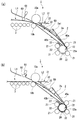
- FIG.2 and FIG.3 is a figure for demonstrating winding operation
- the metal plate 2 that has passed through a rolling mill (not shown) is conveyed along the pass line L1 and reaches the pinch rolls 10a and 10b.
- the metal plate 2 is guided to the winding line L2 bent from the pass line L1 after passing through the pinch rolls 10a and 10b and changing the sheet passing angle obliquely downward.
- the tip of the metal plate 2 is curved so as to draw an arc without being extremely bent.
- the upstream side of the pinch rolls 10a and 10b is also curved and rises with respect to the pass line L1.
- the bending roll driving device 61 brings the bending roll 60 disposed on the upstream side of the pinch rolls 10a and 10b closer to the pass line L1, and lifts the metal plate 2 on the upstream side of the pinch rolls 10a and 10b. suppress.
- the tip of the metal plate 2 is brought close to the side where the second guide surface 32 of the gate 30 and the upper chute guide 40a are arranged, and the curved surface 2a curved upward is contacted below the chute roll 50. Pressure can be applied.
- the metal plate 2 passes between the chute guides 40 a and 40 b while being reduced in friction by the rotation of the chute roll 50, and is guided to the biting opening of the mandrel 20 and the wrapper roll 21. .
- the tip of the metal plate 2 that has passed between the mandrel 20 and the wrapper roll 21 comes into contact with the curved guide surface 22 a of the wrapper apron 22.
- the tip of the metal plate 2 does not bend very much only by the biting of only one wrapper roll 21, so that the static friction between the tip of the metal plate 2 and the wrapper apron 22 is achieved.
- a pushing force in the advancing direction is required to remove the constraint by force.
- the metal plate 2 When the tip of the metal plate 2 comes into contact with the wrapper apron 22, the metal plate 2 is sequentially conveyed, so that the metal plate 2 tends to bulge upward (shown by a dotted line in FIG. 3A).
- the chute roll 50 is exposed to the winding line L ⁇ b> 2 when the tip of the metal plate 2 is wound around the mandrel 20, and suppresses deformation of the metal plate 2 that curves toward the upward surface side.
- the chute roll 50 rotates due to contact friction with the metal plate 2 and converts the force to swell the metal plate 2 into a pushing force in the traveling direction.
- the chute roll 50 Due to the action of the chute roll 50, a pressing force for releasing the restraint due to the static friction force between the metal plate 2 and the wrapper apron 22 is obtained, and the tip of the metal plate 2 slides on the guide surface 22a of the wrapper apron 22 Then, it is bitten by the next wrapper roll 21 arranged on the downstream side thereof.
- the metal plate 2 is stabilized to the mandrel 20 as shown in FIG. 3B without the tip of the metal plate 2 striking the wrapper apron 22. Can be rolled up.
- the chute roll 50 is disposed at a position corresponding to the intermediate position of the tangential path t connecting the peripheral surface of the pinch roll 10b and the peripheral surface of the mandrel 20.
- the top portion 2a1 of the curved surface 2a of the metal plate 2 often occurs at an intermediate position between the pinch rolls 10a and 10b and the mandrel 20, as shown in FIG.
- the chute roll 50 is brought into contact with the top portion 2a1 of the curved surface 2a of the metal plate 2, and the deformation of bending the metal plate 2 toward the upward surface side is effective. Can be suppressed.
- the chute roll 50 is disposed away from the tangential path t connecting the peripheral surfaces of the pinch rolls 10 a and 10 b and the peripheral surface of the mandrel 20.
- the metal plate 2 cannot bulge upward, and the force to swell can be converted into a pressing force in the traveling direction.
- the metal plate 2 may be deformed unexpectedly, for example, the metal plate 2 may be bent to the opposite downward surface side. For this reason, in the present embodiment, the chute roll 50 is separated from the tangential path t, and the force for expanding the metal plate 2 is easily converted into the pressing force in the traveling direction.
- the pinch rolls 10a and 10b that guide the metal plate 2 conveyed along the pass line L1 to the winding line L2 bent from the pass line L1, and the winding line L2.
- a coiler device 1 having a mandrel 20 that winds up the metal plate 2 disposed at the tip of the metal plate 2, and is exposed to the winding line L 2 when at least the tip of the metal plate 2 winds around the mandrel 20.
- FIG. 4 is a configuration diagram showing the coiler device 1 according to the second embodiment of the present invention.
- the second embodiment is different from the above-described embodiment in that a chute roll driving device 51 is provided.
- the chute roll 50 of the second embodiment is supported by the chute roll driving device 51 and is provided so as to be able to appear and retract with respect to the winding line L2.
- the chute roll driving device 51 has a chute roll 50 that protrudes from the second guide surface 32 of the gate 30 (shown by a dotted line in FIG. 4) and a retracted position that retreats from the second guide surface 32 of the gate 30. (Indicated by a solid line in FIG. 4).
- the chute roll driving device 51 moves the chute roll 50 to the protruding position when the tip of the metal plate 2 winds around the mandrel 20, and moves the chute roll 50 to the retracted position after the tip of the metal plate 2 winds around the mandrel 20. It is supposed to let you.
- the chute roll driving device 51 is composed of, for example, a cylinder device.
- the chute roll driving device 51 can retract the chute roll 50 from the winding line L ⁇ b> 2 after the tip of the metal plate 2 is wound around the mandrel 20. it can. After the tip of the metal plate 2 is wound around the mandrel 20, no guide by the chute roll 50 is required. Therefore, the chute roll 50 and the metal plate 2 are prevented from contacting each other by retracting the chute roll 50 from the winding line L2. To. Thereby, abrasion of the chute
- the configuration in which the chute roll is rotatably provided has been described, but the present invention is not limited to this configuration.
- shoot roll by connecting with a motor apparatus etc. may be sufficient. Since the chute roll rotates, a further pressing force can be applied to the metal plate, so that the metal plate can be wound around the mandrel more smoothly.
- the present invention is not limited to this configuration, and for example, the diameter A configuration in which a plurality of thin chute rolls are provided may be employed.
- the present invention is not limited to this configuration, and for example, the wrapper around the mandrel.
- a configuration in which a belt is provided may be employed.
Abstract
Description
この構成を採用することによって、本発明では、少なくとも金属板の先端がマンドレルに巻き付くときに巻取ラインに露出するシュートロールによって、金属板のその上向き面側に湾曲する変形を抑制する。金属板の膨らみがシュートロールによって阻まれると、シュートロールが金属板との接触摩擦により回転し、金属板の膨らもうとする力を進行方向の押力に変換する。これにより、金属板の先端がラッパーエプロン等に突っかかることがなくなり、金属板をマンドレルに安定して巻き取ることができる。 In order to solve the above problems, the present invention provides a pinch roll that guides a metal plate conveyed along a pass line to a winding line bent from the pass line, and is disposed at the tip of the winding line. A mandrel that winds up the metal plate, and a chute roll that suppresses deformation that is exposed to the winding line when at least the tip of the metal plate winds around the mandrel and curves upward on the metal plate. A coiler device having a chute roll is employed.
By adopting this configuration, in the present invention, at least when the tip of the metal plate is wound around the mandrel, the chute roll exposed to the winding line suppresses deformation of the metal plate that curves toward the upward surface side. When the swelling of the metal plate is blocked by the chute roll, the chute roll rotates due to the contact friction with the metal plate, and converts the force to swell the metal plate into a pressing force in the traveling direction. As a result, the tip of the metal plate does not stick to the wrapper apron or the like, and the metal plate can be stably wound around the mandrel.
この構成を採用することによって、本発明では、シュートロールを金属板の湾曲面の頂部に接触させることにより、金属板の膨らみを効果的に抑えることができる。 Moreover, in this invention, the said chute | shoot roll contacts the top part of the curved surface of the said metal plate, and the structure of suppressing the deformation | transformation which curves to the upward surface side of the said metal plate is employ | adopted.
By adopting this configuration, in the present invention, the bulge of the metal plate can be effectively suppressed by bringing the chute roll into contact with the top of the curved surface of the metal plate.
この構成を採用することによって、本発明では、金属板が高強度厚み材の場合、金属板の湾曲面の頂部は、ピンチロールの周面とマンドレルの周面とを結ぶ接線経路の中間位置に生じる場合が多いため、この中間位置に対応する位置にシュートロールを配置することにより、金属板の膨らみを効果的に抑えることができる。 In the present invention, a configuration is adopted in which the chute roll is disposed at a position corresponding to an intermediate position of a tangential path connecting the peripheral surface of the pinch roll and the peripheral surface of the mandrel.
By adopting this configuration, in the present invention, when the metal plate is a high-strength thick material, the top of the curved surface of the metal plate is at an intermediate position of the tangential path connecting the peripheral surface of the pinch roll and the peripheral surface of the mandrel. Since this often occurs, the bulge of the metal plate can be effectively suppressed by arranging the chute roll at a position corresponding to the intermediate position.
この構成を採用することによって、本発明では、ピンチロールの周面とマンドレルの周面とを結ぶ接線経路から離間してシュートロールを配置することにより、金属板の膨らもうとする力を進行方向の押力に変換させ易くすることができる。 Moreover, in this invention, the structure that the said chute | shoot roll is spaced apart from the tangent path | route which connects the surrounding surface of the said pinch roll and the surrounding surface of the said mandrel is employ | adopted.
By adopting this configuration, in the present invention, by placing the chute roll away from the tangential path connecting the peripheral surface of the pinch roll and the peripheral surface of the mandrel, the force to expand the metal plate is advanced. It is possible to facilitate conversion into a direction pressing force.
この構成を採用することによって、本発明では、少なくとも金属板の先端がマンドレルに巻き付くときに、ピンチロールよりも上流側に配置されたベンディングロールをパスラインに近接させ、ピンチロールよりも上流側における金属板の浮き上がりを抑えることで、金属板がシュートロールの下方に接触するよう圧力を加えることができる。 Further, in the present invention, a bending roll disposed upstream of the pinch roll and capable of approaching and separating from the pass line, and the bending roll at least when the tip of the metal plate winds around the mandrel. A configuration is adopted in which a bending roll driving device is provided in proximity to the pass line.
By adopting this configuration, in the present invention, when at least the tip of the metal plate is wound around the mandrel, the bending roll disposed upstream of the pinch roll is brought close to the pass line, and the upstream side of the pinch roll. By suppressing the lifting of the metal plate at, pressure can be applied so that the metal plate contacts the lower side of the chute roll.
この構成を採用することによって、本発明では、金属板の先端がマンドレルに巻き付いた後はシュートロールによるガイドが不要となるため、シュートロールを巻取ラインから退避させる。これにより、シュートロールの摩耗を抑制することができる。 Further, in the present invention, the chute roll is provided so as to be able to protrude and retract with respect to the winding line, and the chute for retracting the chute roll from the winding line after the tip of the metal plate is wound around the mandrel. A configuration of having a roll driving device is employed.
By adopting this configuration, in the present invention, after the tip of the metal plate is wound around the mandrel, the guide by the shoot roll becomes unnecessary, and therefore the shoot roll is retracted from the winding line. Thereby, wear of the chute roll can be suppressed.
図1は、本発明の第1実施形態におけるコイラー装置1を示す構成図である。
本実施形態のコイラー装置1は、不図示の圧延機の下流側に配置され、圧延機を通過しパスラインL1に沿って搬送される金属板2(後述する図2及び図3参照)を巻取ラインL2に導入して巻き取るものである。パスラインL1は、水平に並んだ複数の搬送ロール3によって形成されている。 (First embodiment)
FIG. 1 is a configuration diagram showing a
The
図2及び図3は、本発明の第1実施形態におけるコイラー装置1の巻き取り動作を説明するための図である。 Next, the winding operation of the
FIG.2 and FIG.3 is a figure for demonstrating winding operation | movement of the
金属板2は、図2(b)に示すように、ピンチロール10a,10bを通過した後、通板角度を斜め下方に変えて、パスラインL1から曲がった巻取ラインL2に導かれる。ここで、金属板2が高強度厚み材の場合、その先端が極端に曲がらずに、弧を描くように湾曲する。 As shown in FIG. 2A, the
As shown in FIG. 2 (b), the
以上により、コイラー装置1による金属板2の巻き取り動作が完了する。 As shown in FIG. 3B, when the tip of the
Thus, the winding operation of the
次に、本発明の第2実施形態について説明する。以下の説明において、上述の実施形態と同一又は同等の構成部分については同一の符号を付し、その説明を簡略若しくは省略する。 (Second Embodiment)
Next, a second embodiment of the present invention will be described. In the following description, the same or equivalent components as those of the above-described embodiment are denoted by the same reference numerals, and the description thereof is simplified or omitted.
図4に示すように、第2実施形態では、シュートロール駆動装置51が設けられている点で、上記実施形態と異なる。
第2実施形態のシュートロール50は、シュートロール駆動装置51に支持されており、巻取ラインL2に対し出没可能に設けられている。 FIG. 4 is a configuration diagram showing the
As shown in FIG. 4, the second embodiment is different from the above-described embodiment in that a chute
The
2 金属板
2a 湾曲面
2a1 頂部
10a,10b ピンチロール
20 マンドレル
50 シュートロール
51 シュートロール駆動装置
60 ベンディングロール
61 ベンディングロール駆動装置
L1 パスライン
L2 巻取ライン
t 接線経路 DESCRIPTION OF
Claims (6)
- パスラインに沿って搬送される金属板を該パスラインから曲がった巻取ラインに導くピンチロールと、
前記巻取ラインの先に配置されて前記金属板を巻き取るマンドレルと、
少なくとも前記金属板の先端が前記マンドレルに巻き付くときに前記巻取ラインに露出し、前記金属板のその上向き面側に湾曲する変形を抑制するシュートロールと、を有する、ことを特徴とするシュートロールを備えたコイラー装置。 A pinch roll that guides a metal plate conveyed along the pass line to a winding line bent from the pass line;
A mandrel disposed at the end of the winding line to wind up the metal plate;
A chute roll that is exposed to the winding line when at least the tip of the metal plate winds around the mandrel and suppresses deformation of the metal plate that curves toward the upward surface side thereof. A coiler device with a roll. - 前記シュートロールは、前記金属板の湾曲面の頂部と接触して、前記金属板のその上向き面側に湾曲する変形を抑制する、ことを特徴とする請求項1に記載のシュートロールを備えたコイラー装置。 The chute roll according to claim 1, wherein the chute roll is in contact with a top portion of the curved surface of the metal plate and suppresses deformation of the metal plate that curves toward the upward surface side thereof. Coiler equipment.
- 前記シュートロールは、前記ピンチロールの周面と前記マンドレルの周面とを結ぶ接線経路の中間位置に対応する位置に配置されている、ことを特徴とする請求項1または2に記載のシュートロールを備えたコイラー装置。 The chute roll according to claim 1, wherein the chute roll is disposed at a position corresponding to an intermediate position of a tangential path connecting a peripheral surface of the pinch roll and a peripheral surface of the mandrel. Coiler device with
- 前記シュートロールは、前記ピンチロールの周面と前記マンドレルの周面とを結ぶ接線経路から離間して配置されている、ことを特徴とする請求項1~3のいずれか一項に記載のシュートロールを備えたコイラー装置。 The chute according to any one of claims 1 to 3, wherein the chute roll is disposed apart from a tangential path connecting a peripheral surface of the pinch roll and a peripheral surface of the mandrel. A coiler device with a roll.
- 前記ピンチロールよりも上流側に配置され、前記パスラインに対して近接離間可能なベンディングロールと、
少なくとも前記金属板の先端が前記マンドレルに巻き付くときに前記ベンディングロールを前記パスラインに近接させるベンディングロール駆動装置と、を有する、ことを特徴とすることを特徴とする請求項1~4のいずれか一項に記載のシュートロールを備えたコイラー装置。 A bending roll that is disposed upstream of the pinch roll and is capable of approaching and separating from the pass line;
5. A bending roll driving device for bringing the bending roll close to the pass line when at least a tip of the metal plate is wound around the mandrel. A coiler device comprising the chute roll according to claim 1. - 前記シュートロールは、前記巻取ラインに対し出没可能に設けられており、
前記金属板の先端が前記マンドレルに巻き付いた後に前記シュートロールを前記巻取ラインから退避させるシュートロール駆動装置を有する、ことを特徴とする請求項1~5のいずれか一項に記載のシュートロールを備えたコイラー装置。 The chute roll is provided so as to be able to appear and retract with respect to the winding line,
The chute roll according to any one of claims 1 to 5, further comprising a chute roll driving device that retracts the chute roll from the take-up line after the tip of the metal plate is wound around the mandrel. Coiler device with
Priority Applications (4)
| Application Number | Priority Date | Filing Date | Title |
|---|---|---|---|
| CN201580014811.XA CN106255558B (en) | 2014-03-20 | 2015-03-18 | The winding device for having sliding slot roller |
| EP15764398.2A EP3120945B1 (en) | 2014-03-20 | 2015-03-18 | Coiler device provided with chute roller and bending roller |
| US15/127,233 US10406578B2 (en) | 2014-03-20 | 2015-03-18 | Coiler device provided with chute roller |
| KR1020167025459A KR102080971B1 (en) | 2014-03-20 | 2015-03-18 | Coiler device provided with chute roller |
Applications Claiming Priority (2)
| Application Number | Priority Date | Filing Date | Title |
|---|---|---|---|
| JP2014-059065 | 2014-03-20 | ||
| JP2014059065A JP6298331B2 (en) | 2014-03-20 | 2014-03-20 | Coiler device with chute roll |
Publications (1)
| Publication Number | Publication Date |
|---|---|
| WO2015141702A1 true WO2015141702A1 (en) | 2015-09-24 |
Family
ID=54144666
Family Applications (1)
| Application Number | Title | Priority Date | Filing Date |
|---|---|---|---|
| PCT/JP2015/057976 WO2015141702A1 (en) | 2014-03-20 | 2015-03-18 | Coiler device provided with chute roller |
Country Status (6)
| Country | Link |
|---|---|
| US (1) | US10406578B2 (en) |
| EP (1) | EP3120945B1 (en) |
| JP (1) | JP6298331B2 (en) |
| KR (1) | KR102080971B1 (en) |
| CN (1) | CN106255558B (en) |
| WO (1) | WO2015141702A1 (en) |
Families Citing this family (2)
| Publication number | Priority date | Publication date | Assignee | Title |
|---|---|---|---|---|
| EP4019158B1 (en) * | 2020-12-23 | 2023-11-01 | Primetals Technologies Austria GmbH | Reel device for large thickness range of metal strips |
| EP4101556A1 (en) * | 2021-06-10 | 2022-12-14 | Primetals Technologies Austria GmbH | Roller conveyor section for large thickness range of metal strips |
Citations (4)
| Publication number | Priority date | Publication date | Assignee | Title |
|---|---|---|---|---|
| JPS5868423A (en) * | 1981-10-20 | 1983-04-23 | Kawasaki Steel Corp | Coiling method for material to be rolled |
| JPH02133114A (en) * | 1988-11-15 | 1990-05-22 | Kawasaki Steel Corp | Coiling equipment for hot rolled steel tape |
| JPH04228217A (en) * | 1990-05-16 | 1992-08-18 | Sumitomo Metal Ind Ltd | Device for switching transporting direction of hot rolled steel strip and device for coiling |
| JP2012250283A (en) * | 2011-06-07 | 2012-12-20 | Jfe Steel Corp | Apparatus and method for winding hot-rolled steel strip |
Family Cites Families (16)
| Publication number | Priority date | Publication date | Assignee | Title |
|---|---|---|---|---|
| US2937821A (en) * | 1955-09-12 | 1960-05-24 | United Eng Foundry Co | Apparatus for coiling strip material |
| US2918226A (en) * | 1956-09-04 | 1959-12-22 | United Eng Foundry Co | Apparatus for coiling strip material |
| GB952449A (en) | 1959-10-20 | 1964-03-18 | Davy & United Eng Co Ltd | Improvements in or relating to strip mills |
| GB1204817A (en) * | 1967-11-18 | 1970-09-09 | Siemag Siegener Masch Bau | Strip coiler |
| JPS5625326B2 (en) | 1973-03-29 | 1981-06-11 | ||
| JPS5028464A (en) | 1973-07-18 | 1975-03-24 | ||
| JPS57156832A (en) * | 1981-03-25 | 1982-09-28 | Sumitomo Metal Ind Ltd | Coiling method for hot strip |
| JPS59168209U (en) * | 1983-04-25 | 1984-11-10 | シャープ株式会社 | Hair removal liquid heating device |
| JP2537299B2 (en) * | 1990-07-25 | 1996-09-25 | 川崎製鉄株式会社 | Winding auxiliary device with fluid guiding device |
| JP4358673B2 (en) | 2004-04-16 | 2009-11-04 | 新日本製鐵株式会社 | Strip winding method and apparatus |
| FR2876365B1 (en) * | 2004-10-12 | 2011-08-26 | Vai Clecim | METHOD AND APPARATUS FOR COIL WINDING OF A BAND |
| DE102007045698A1 (en) * | 2006-09-25 | 2008-04-03 | Sms Demag Ag | Method for winding metal strip on to spindle to form reel uses swiveling tension sensor to measure tension of strip during winding which is pivoted on reel frame |
| AT506331B1 (en) * | 2008-02-08 | 2010-03-15 | Siemens Vai Metals Tech Gmbh | METHOD AND BENDING DEVICE FOR PROGRESSIVELY BENDING A METAL STRIP IN THE MOUNTING AREA OF A THINNESS BELT HASPING DEVICE |
| CN101623720B (en) * | 2008-07-09 | 2011-11-16 | 上海格林赛高新材料有限公司 | Coiling apparatus for controlling strip type of special metal strip |
| CN103191956B (en) * | 2012-01-05 | 2015-05-06 | 鞍钢股份有限公司 | Coiler guide and guard device |
| US9566626B2 (en) * | 2013-12-04 | 2017-02-14 | Sms Group Gmbh | Apparatus for and method of winding-up a metal strip, and plant for producing a metal strip windable into a coil |
-
2014
- 2014-03-20 JP JP2014059065A patent/JP6298331B2/en active Active
-
2015
- 2015-03-18 CN CN201580014811.XA patent/CN106255558B/en active Active
- 2015-03-18 EP EP15764398.2A patent/EP3120945B1/en active Active
- 2015-03-18 WO PCT/JP2015/057976 patent/WO2015141702A1/en active Application Filing
- 2015-03-18 US US15/127,233 patent/US10406578B2/en active Active
- 2015-03-18 KR KR1020167025459A patent/KR102080971B1/en active IP Right Grant
Patent Citations (4)
| Publication number | Priority date | Publication date | Assignee | Title |
|---|---|---|---|---|
| JPS5868423A (en) * | 1981-10-20 | 1983-04-23 | Kawasaki Steel Corp | Coiling method for material to be rolled |
| JPH02133114A (en) * | 1988-11-15 | 1990-05-22 | Kawasaki Steel Corp | Coiling equipment for hot rolled steel tape |
| JPH04228217A (en) * | 1990-05-16 | 1992-08-18 | Sumitomo Metal Ind Ltd | Device for switching transporting direction of hot rolled steel strip and device for coiling |
| JP2012250283A (en) * | 2011-06-07 | 2012-12-20 | Jfe Steel Corp | Apparatus and method for winding hot-rolled steel strip |
Also Published As
| Publication number | Publication date |
|---|---|
| KR102080971B1 (en) | 2020-02-24 |
| US20170106422A1 (en) | 2017-04-20 |
| CN106255558B (en) | 2019-05-14 |
| KR20160120768A (en) | 2016-10-18 |
| US10406578B2 (en) | 2019-09-10 |
| JP6298331B2 (en) | 2018-03-20 |
| EP3120945A4 (en) | 2017-12-06 |
| EP3120945A1 (en) | 2017-01-25 |
| CN106255558A (en) | 2016-12-21 |
| EP3120945B1 (en) | 2020-07-22 |
| JP2015182089A (en) | 2015-10-22 |
Similar Documents
| Publication | Publication Date | Title |
|---|---|---|
| US8096157B2 (en) | Method and device for rolling up a metal strip | |
| WO2015141702A1 (en) | Coiler device provided with chute roller | |
| JP6171532B2 (en) | Guide plate device for hot rolling line | |
| JP5353260B2 (en) | Winding equipment and winding method for high-strength thick hot-rolled steel sheet | |
| KR101368259B1 (en) | Winding apparatus for material | |
| KR100807147B1 (en) | Apparatus for adjusting the angle for binder | |
| JP2012250283A (en) | Apparatus and method for winding hot-rolled steel strip | |
| JP2016107296A (en) | Separator device, apparatus and method for manufacturing coil product | |
| KR102074554B1 (en) | Coiler device and gate device provided with guide unit | |
| JP6035847B2 (en) | Metal strip winding equipment | |
| US2207832A (en) | Coiler | |
| JP2013006187A (en) | Apparatus and method for rolling short size material | |
| JP2006281248A (en) | Side guide | |
| WO2015141701A1 (en) | Coiler device provided with wrapper aprons | |
| JP2011240396A (en) | Method for straightening metal strip | |
| JP6399960B2 (en) | Metal strip winding device and metal strip winding method | |
| JP6409610B2 (en) | Material flutter suppression device | |
| US1657309A (en) | Uncoiler and method of operating the same | |
| JP5353258B2 (en) | Winding method and winding device for high strength thick hot rolled steel sheet | |
| JP2010264493A (en) | Device and method for winding high-strength thick hot-rolled steel sheet | |
| JP5311182B2 (en) | Tape sticking device | |
| JP2012045609A (en) | Equipment for side guide and guide method for metal strip | |
| KR101428195B1 (en) | Separation preventing apparatus for chain | |
| JP7077755B2 (en) | Rolling bending equipment | |
| JP5353257B2 (en) | Winding method of high-strength thick-walled hot-rolled steel sheet |
Legal Events
| Date | Code | Title | Description |
|---|---|---|---|
| 121 | Ep: the epo has been informed by wipo that ep was designated in this application |
Ref document number: 15764398 Country of ref document: EP Kind code of ref document: A1 |
|
| ENP | Entry into the national phase |
Ref document number: 20167025459 Country of ref document: KR Kind code of ref document: A |
|
| REEP | Request for entry into the european phase |
Ref document number: 2015764398 Country of ref document: EP |
|
| WWE | Wipo information: entry into national phase |
Ref document number: 2015764398 Country of ref document: EP |
|
| WWE | Wipo information: entry into national phase |
Ref document number: 15127233 Country of ref document: US |
|
| NENP | Non-entry into the national phase |
Ref country code: DE |