WO2015141529A1 - 入力装置および入力制御プログラム - Google Patents
入力装置および入力制御プログラム Download PDFInfo
- Publication number
- WO2015141529A1 WO2015141529A1 PCT/JP2015/057043 JP2015057043W WO2015141529A1 WO 2015141529 A1 WO2015141529 A1 WO 2015141529A1 JP 2015057043 W JP2015057043 W JP 2015057043W WO 2015141529 A1 WO2015141529 A1 WO 2015141529A1
- Authority
- WO
- WIPO (PCT)
- Prior art keywords
- input
- user
- user input
- dominant hand
- hand
- Prior art date
- Legal status (The legal status is an assumption and is not a legal conclusion. Google has not performed a legal analysis and makes no representation as to the accuracy of the status listed.)
- Ceased
Links
Images




Classifications
-
- G—PHYSICS
- G06—COMPUTING OR CALCULATING; COUNTING
- G06F—ELECTRIC DIGITAL DATA PROCESSING
- G06F3/00—Input arrangements for transferring data to be processed into a form capable of being handled by the computer; Output arrangements for transferring data from processing unit to output unit, e.g. interface arrangements
- G06F3/01—Input arrangements or combined input and output arrangements for interaction between user and computer
- G06F3/048—Interaction techniques based on graphical user interfaces [GUI]
- G06F3/0487—Interaction techniques based on graphical user interfaces [GUI] using specific features provided by the input device, e.g. functions controlled by the rotation of a mouse with dual sensing arrangements, or of the nature of the input device, e.g. tap gestures based on pressure sensed by a digitiser
- G06F3/0488—Interaction techniques based on graphical user interfaces [GUI] using specific features provided by the input device, e.g. functions controlled by the rotation of a mouse with dual sensing arrangements, or of the nature of the input device, e.g. tap gestures based on pressure sensed by a digitiser using a touch-screen or digitiser, e.g. input of commands through traced gestures
- G06F3/04886—Interaction techniques based on graphical user interfaces [GUI] using specific features provided by the input device, e.g. functions controlled by the rotation of a mouse with dual sensing arrangements, or of the nature of the input device, e.g. tap gestures based on pressure sensed by a digitiser using a touch-screen or digitiser, e.g. input of commands through traced gestures by partitioning the display area of the touch-screen or the surface of the digitising tablet into independently controllable areas, e.g. virtual keyboards or menus
-
- G—PHYSICS
- G06—COMPUTING OR CALCULATING; COUNTING
- G06F—ELECTRIC DIGITAL DATA PROCESSING
- G06F2203/00—Indexing scheme relating to G06F3/00 - G06F3/048
- G06F2203/048—Indexing scheme relating to G06F3/048
- G06F2203/04803—Split screen, i.e. subdividing the display area or the window area into separate subareas
Definitions
- the present invention relates to an input device that can simultaneously acquire a plurality of user inputs.
- an input device that accepts handwritten input using an indicator such as a stylus pen, a mouse, or a user's fingertip, and recognizes a character or a figure written (drawn) by a user from a locus (handwriting) of the handwritten input.
- an input device that invalidates user input other than the locus of handwritten input is also known.
- An example of such an input device is disclosed in Patent Documents 1 to 3, for example.
- Patent Document 1 discloses a technique for rejecting contact caused by a palm when the palm is placed on a detection area. That is, in the technique of Patent Document 1, when user input by a stylus pen and user input by finger contact are detected, the former input is preferentially received.
- Patent Document 2 discloses a technique in which a handwritten area that accepts handwriting input and a touchable area that is not accepted as handwritten input even when touching the touch panel is disclosed.
- Patent Document 3 discloses a technique for setting an invalid input area for invalidating an erroneous input performed because a hand holding a pen touches a tablet for each handwriting input frame.
- Japanese Patent Publication Japanese Unexamined Patent Publication No. 2011-108276 (published on June 2, 2011)” Japanese Patent Publication “JP 2013-196283 A (published on September 30, 2013)” Japanese Patent Publication “Japanese Patent Laid-Open No. 9-44393 (published on Feb. 14, 1997)”
- Patent Document 1 does not reject contact caused by a palm or preferentially obtain user input by a stylus pen according to the user's dominant hand. Further, in the techniques of Patent Documents 2 and 3, user input by a dominant hand that touches the screen is invalidated on the assumption that a hand-able area or an input invalid area is set. That is, in these techniques, the user input to be invalidated is not determined from the plurality of acquired user inputs without setting the area.
- the present application has been made in view of the above problems, and an object thereof is to provide an input device or the like that can acquire user input intended by the user according to the dominant hand.
- an input device including a planar member capable of simultaneously acquiring a plurality of user inputs, and determines a dominant hand of a user. And an effective area changing unit that changes an area to be extracted as an effective user input out of a plurality of user inputs by the dominant hand acquired by the planar member according to the dominant hand determined by the dominant hand determination unit. It is equipped with.
- the user input intended by the user can be acquired according to the dominant hand.
- FIG. 2 is a diagram illustrating a schematic configuration of the input device 1.
- the input device 1 is a plate-like housing including a display unit 2 and a touch panel (planar member) 3, for example, a tablet terminal.
- the display unit 2 displays, for example, various images such as images resulting from the execution of various functions (application software) installed in the input device 1.
- an LCD Liquid crystal display
- the touch panel 3 detects the contact (or approach) of the stylus pen 20 as shown in FIG. 2A or the user's finger (for example, index finger) as shown in FIG. Get the input.
- the touch panel 3 can simultaneously acquire a plurality of user inputs (multi-point detection).
- the touch panel 3 is, for example, a capacitive touch panel stacked on the display unit 2.
- the camera unit 6 is an imaging unit that images a subject. These display unit 2, touch panel 3 and camera unit 6 are controlled by a control unit 4 which will be described later.
- the input device 1 acquires (detects) the locus of the stylus pen 20 or the finger as user input by the touch panel 3 and displays an image in which the locus can be visually recognized along the acquired locus on the display unit 2. .
- the function of handwriting input is realized. That is, in the input device 1, for example, handwriting input software is executed as application software.
- the input device 1 may be a portable information terminal such as a smartphone. Moreover, it may not be a portable information terminal, but can be realized by various information terminals including at least the display unit 2 and the touch panel 3.
- the input device 1 can be effectively applied to an information terminal such as an information terminal that can be used by being placed on a desk or the like, which may input a part of a dominant hand on the display surface of the display unit 2 at the time of user input.
- the touch panel 3 may not be a capacitive type, and an optical sensor may be used instead of the touch panel 3. In other words, the touch panel 3 may be configured to be capable of multipoint detection of the detection target.
- FIG. 1 is a block diagram showing a specific configuration of the input device 1.
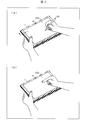
- FIGS. 3A and 3B are diagrams for explaining extraction of effective user input.
- FIG. 3A shows a case where the dominant hand is the right hand and
- FIG. 3B shows a case where the dominant hand is the left hand.
- the input device 1 includes a display unit 2, a touch panel 3, a control unit 4, and a storage unit 5.
- the control unit 4 comprehensively controls the input device 1 and mainly includes a dominant hand setting unit 41, a dominant hand determination unit 42, a touch position detection unit 43, a touch position comparison unit (effective region changing unit) 44, an invalid region.
- a setting / confirming unit (invalid setting unit) 45 and a display control unit 46 are provided.
- the storage unit 5 stores various control programs executed by the control unit 4.
- the storage unit 5 is configured by a nonvolatile storage device such as a hard disk or a flash memory.
- the dominant hand setting unit 41 sets the user's dominant hand.
- the input device 1 or an application of the input device 1 that requires the dominant hand setting (for example, the hand of the stylus pen 20) is used to determine which hand is a user input that should be acquired as valid user input (for example, Set to (Handwriting input software).
- the dominant hand information indicating the set dominant hand is transmitted to the dominant hand determination unit 42.
- the dominant hand setting unit 41 transmits, for example, a display instruction of a dominant hand selection screen for allowing the user to perform dominant hand setting to the display control unit 46.
- the display control unit 46 reads the dominant hand selection screen from the storage unit 5 and causes the display unit 2 to display it.
- the user selects his / her dominant hand (right hand or left hand).
- the dominant hand setting unit 41 receives the touch position (detection result) of the user input acquired by the touch panel 3 from the touch position detection unit 43, the dominant hand setting unit 41 determines which hand is selected as the dominant hand from the touch position, Set the selected hand as the dominant hand.
- the dominant hand determination unit 42 determines the user's dominant hand based on the dominant hand information received from the dominant hand setting unit 41, and transmits the determination result to the touch position comparison unit 44 and the invalid area setting / confirmation unit 45.
- the touch position detection unit 43 detects the touch position of the user input acquired by the touch panel 3. When a plurality of user inputs are acquired simultaneously, the touch position of each user input is detected.
- the detection result acquired at the time of dominant hand setting is transmitted to the dominant hand setting unit 41, and the detection result acquired at other times (for example, at the time of handwriting input) is transmitted to the touch position comparison unit 44 and the invalid area setting / confirmation unit 45, respectively. .
- the touch position comparison unit 44 changes the effective region (region) C to be extracted as an effective user input among the plurality of user inputs obtained by the dominant hand, which the touch panel 3 has acquired, according to the dominant hand determined by the dominant hand determination unit 42. (Switch).
- the dominant hand is the right hand
- the display surface includes the vicinity of the little finger of the right hand and the stylus pen 20.
- the pen tip comes into contact.
- the touch panel 3 acquires a plurality of user inputs by the dominant hand in a contact area C (an overall contact area by the dominant hand) that is an area in which they touch.
- the touch position comparison unit 44 determines a part thereof as an effective area E to be extracted as an effective user input.
- the touch position comparison unit 44 compares the touch positions of a plurality of user inputs with the right hand. . Then, among the plurality of user inputs, at least one of the user inputs acquired relatively on the left side when viewing the touch panel 3 is extracted as an effective user input. In (a) of FIG. 3, it determines as the effective area
- the touch position comparison unit 44 is relatively on the right side when viewing the touch panel 3 among a plurality of user inputs by the left hand. At least one of the acquired user inputs is extracted as a valid user input. In (b) of FIG. 3, it determines as the effective area
- the tip of the stylus pen 20 or the index finger of the dominant hand moves the touch panel 3 more than the vicinity of the little finger.
- the display surface In the left region when viewed (on the side of the handle (the user's finger that does not perform user input, the non-dominant hand)), the display surface is touched.
- the tip of the pen tip or the index finger comes into contact with the display surface in the right side region (the handle side) when the touch panel 3 is viewed from the vicinity of the little finger.
- the dominant hand when the dominant hand is the right hand, the user input on the left side when viewing the touch panel 3 is effective, and when the dominant hand is the left hand, the user input on the right side when viewing the touch panel 3 is the effective user.
- the dominant hand By acquiring as input, it is possible to appropriately acquire user input by the stylus pen 20 or the index finger of the dominant hand. That is, according to the dominant hand, the user input intended by the user can be appropriately acquired as an effective user input.
- the dominant hand if the dominant hand is the right hand, the leftmost user input when viewing the touch panel 3, and if the dominant hand is the left hand, the rightmost user when viewing the touch panel 3 is displayed.
- Each input may be a valid user input.
- the contact area including the right side is the effective area E, and all the plurality of user inputs in the effective area E are extracted as effective user inputs. Thereby, the drawing state corresponding to various input modes can be faithfully displayed on the display unit 2.
- the size of the effective area E does not necessarily coincide with the contact area, and may be set so that the drawing intended by the user (image display along the locus of the pen tip or the finger) can be performed.
- region is simplified and illustrated for description.
- the contact area C the contact area in the vicinity of the little finger is illustrated in a rectangular shape in consideration of ease of viewing.
- the contact area of the pen tip (effective area E) is also illustrated in a circular shape larger than the pen tip.
- the invalid area setting / confirming unit 45 sets an invalid input area (insensitive area) that invalidates the user input acquired by the touch panel 3. Further, it is confirmed whether or not there is a user input in the input invalid area, and whether the user input is valid or invalid is determined.
- the invalid area setting / confirming unit 45 sets an input invalid area for the touch panel 3 in accordance with the determination result received from the dominant hand determination unit 42. That is, when the input invalid area is set, the user input as a touch or a tap acquired by the electrode of the touch panel 3 included in the input invalid area is invalidated. If the stylus pen 20 is used, it can be said that the input device 1 does not recognize the user input (pen input) by the stylus pen 20 in the set input invalid area.
- the invalid area setting / confirming unit 45 displays the left side area L of the touch panel 3 when the touch panel 3 is viewed as the input invalid area, for example, as shown in FIG. Set the invalid area AL.
- the dominant hand is the left hand, for example, as shown in FIG. 3B
- the right invalid area AR is set as the input invalid area in the right end area R of the touch panel 3 when the touch panel 3 is visually recognized. That is, at least a part of the area near the edge (screen edge) of the display surface opposite to the dominant hand of the display unit 2 is set as an input invalid area.
- the touch position comparison unit 44 extracts a relatively left user input as a valid user input if the dominant hand is the right hand, and a relatively left user input if the dominant hand is the left hand. .
- the user input by the part may be erroneously detected as an effective user input. Therefore, such an erroneous detection can be prevented in advance by setting the input invalid area by the invalid area setting / confirming unit 45. In other words, user input by the stylus pen 20 can be appropriately acquired.
- setting the input invalid area is particularly effective when the input device 1 is gripped and used. That is, even when handwriting input is performed while holding the input device 1 by hand, user input intended by the user (for example, user input by the stylus pen 20) can be acquired.
- the number of pixels in the longitudinal direction of the display surface of the display unit 2 is 1280 pixels (the length of the input device 1 in the longitudinal direction is about 10 inches).
- the widths of the left invalid area AL and right invalid area AR at that time are each 5 pixels wide (about 0.4% of the screen width (length in the longitudinal direction) of the display surface). Is set. For example, the width may be set to about 1% of the screen width.
- the above width also depends on the casing width (bezel width) W of the input device 1 (see FIG. 2A). That is, if the housing width W is wide, the possibility that the handle is in contact with the display surface of the display unit 2 is low, and even if the handle is touched, there is a high possibility that only a part of the handle is touched. Therefore, when the housing width W is wide, the width may be narrow. On the other hand, if the housing width W is narrow (for example, in the case of an input device with a narrow frame), it is highly likely that the handle touches the display surface and the contact area becomes large. Therefore, when the housing width W is narrow, the width is preferably set to be wide so as to include a range that is assumed to be touched by the handle.
- the width may be set so as to prevent a user input by the handle from being erroneously detected.
- the invalid area setting / confirming unit 45 determines the width according to the initial setting value stored in advance in the storage unit 5 and sets the invalid input area, but changes the initial setting value according to a user instruction. May be. Further, whether or not to set an input invalid area may be determined by a user instruction.
- the display control unit 46 displays various images on the display unit 2. For example, the display unit 2 displays the dominant hand selection screen or an image indicating the stylus pen 20 or the trajectory of the finger acquired during handwriting input.
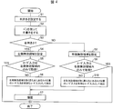
- FIG. 4 is a flowchart showing processing of the input device 1.
- FIG. 4 an example of processing when handwritten input is performed using the stylus pen 20 will be described.
- the dominant hand setting unit 41 sets the dominant hand of the user according to the user's instruction (S1).
- the display control unit 46 causes the display unit 2 to display a handwriting input screen capable of executing handwriting input. Then, the user starts handwriting using the stylus pen 20 on the handwriting input screen (S2).
- the dominant hand determination unit 42 determines whether the user's dominant hand is a right hand or a left hand (whether the user is a right hand or a left hand) (S3).
- the invalid area setting / confirming unit 45 sets the left invalid area AL (S4), and the user input acquired in the process of S2 is the left invalid area AL. It is confirmed whether it was acquired only within (S5). That is, it is confirmed whether or not the touch position from which the user input is acquired exists only in the left invalid area AL.
- the invalid area setting / confirming unit 45 determines that the user input is not acquired only in the left invalid area AL (NO in S5), the invalid area setting / confirming unit 45 notifies the touch position comparing unit 44 to that effect.
- the touch position comparison unit 44 compares the touch positions of a plurality of user inputs, and when viewing the touch panel 3, the user acquired at the touch position existing on the leftmost side excluding the left invalid area AL.
- the input is extracted as a valid user input (S6). That is, the effective area E from which a valid user input is extracted is determined.
- the display control unit 46 reflects the effective user input extracted by the touch position comparison unit 44 (the user input in the effective area E determined by the touch position comparison unit 44) on the handwriting input screen, and displays it on the display unit 2. Let Thereby, drawing (handwriting input) by the stylus pen 20 is started (S7). Then, the display control unit 46 displays the locus of the effective area E on the display unit 2.
- the invalid area setting / confirming unit 45 sets the right invalid area AR (S8), and the user input acquired in the process of S2 is Then, it is confirmed whether or not it is acquired only in the right invalid area AR (S9). If it is determined that the user input is not acquired only in the right invalid area AR (NO in S9), the touch position comparison unit 44 is notified accordingly. Upon receiving the notification, the touch position comparison unit 44, when viewing the touch panel 3 among the touch positions corresponding to a plurality of user inputs, receives the user input at the rightmost touch position excluding the right invalid area AR, Extracted as valid user input (S10). Then, after the process of S10, drawing with the stylus pen 20 is started (S7).
- the determination of S3 may not be performed after the process of S2, but may be performed after the process of S1 (immediately after the dominant hand is set). Further, although the user input at the leftmost touch position in S6 and the user input at the rightmost touch position in S10 (that is, user input at one coordinate) are determined as valid user inputs, as described above, the stylus pen is used.
- a contact area where a detection object such as 20 is in contact may be set as an effective area E, and a plurality of user inputs in the effective area E may be set as effective user inputs.
- the capacitance value obtained by detection of the stylus pen 20 and the capacitance value obtained by detection of the finger are different from those acquired by the touch panel 3.
- the dominant hand is set according to the user input on the dominant hand selection screen.
- the present invention is not limited to this.
- the dominant hand is set by determining which hand is the hand. May be. This example will be described in Embodiment 3.
- the input device 1 extracts an effective user input from among a plurality of user inputs obtained by the dominant hand according to the dominant hand determined by the dominant hand determination unit 42 from the plurality of user inputs acquired by the dominant hand. Change area E.
- the input device 1 can use the pen of the stylus pen 20 regardless of whether the palm of the dominant hand is placed on the display surface of the display unit 2 (when the hand is placed flat) or when a part of the dominant hand such as the little finger is attached. It is possible to draw along the trajectory of the tip portion or the tip portion of the index finger of the dominant hand. That is, when handwritten input is performed while putting a dominant hand on the display surface of the display unit 2, it is possible to prevent a user input not intended by the user from being acquired and a drawing not intended by the user from being performed.
- the inventor of the present application also examined a configuration for acquiring user input with a stylus pen without setting the dominant hand. This is because in consideration of user convenience, it is preferable that the user input can be appropriately acquired without setting a dominant hand for the user.
- the user input acquired on the upper side of the touch panel when viewing the touch panel (the position close to the camera unit 6 in FIG. 2A) is used as the user input by the stylus pen.
- the structure to judge is mentioned. That is, in this configuration, the dominant hand setting is not performed, and the touch position of the user input is determined by the Y coordinate of the touch panel (the coordinate in the short direction of the input device 1 in FIG. 2A).
- the handwriting input method using a stylus pen differs depending on the user. For example, the user who performs handwriting input so that the pen tip of the stylus pen contacts the display surface below the contact position near the little finger (position far from the camera unit 6 in FIG. 2A). Is also present. In this case, since the contact position near the little finger is above the contact position of the pen tip of the stylus pen, user input by the stylus pen cannot be acquired.
- the pen tip touches the display surface on the left side of the touch panel when the touch panel is visually recognized, rather than near the little finger of the right hand, regardless of the user.
- the dominant hand is the left hand
- the pen tip contacts the display surface on the right side of the touch panel when the touch panel is visually recognized, rather than near the little finger of the left hand, regardless of the user. Therefore, the inventor of the present application uses the judgment result of the user's dominant hand in order to appropriately extract user input (valid user input) with the stylus pen, and improves user convenience in handwriting input. I came to the conclusion that That is, the inventor of the present application has found that it is necessary to make a user's dominant hand judgment in the input device and extract effective user input based on the judgment result in order to improve user convenience. .
- the technique of Patent Document 1 does not acquire user input using a stylus pen corresponding to the dominant hand. Further, in the technique of Patent Document 1, when a user input with a wide contact area such as a palm is detected, the contact is regarded as “touched” and ignored, thereby eliminating erroneous input due to “touched”. Therefore, according to the technique, when a user input having a contact area smaller than a contact area that can be recognized as a palm is acquired (for example, only with a little finger), the user input may not be removed. As a result, when drawing is performed using a touch event, there is a possibility that drawing is performed on a contact portion other than the stylus pen.
- the contact area is “with hand”, for example, when only the little finger of the hand holding the stylus pen touches the display surface, the input with “hand” and the input with the stylus pen are performed. There is a possibility that it cannot be distinguished.
- a handleable area is manually set, and in the technique of Patent Document 3, an input invalid area is set along with a handwritten input frame.
- the user input intended by the user can be acquired without setting a handleable area or an input invalid area.
- the input invalid area is set to the screen edge of the display unit 2 and is not set for each handwriting input frame as in the technique of Patent Document 3.
- a band-like input invalid area (left invalid area AL or right invalid area AR) is set at the end of the touch panel 3 according to the dominant hand, and when the touch position exists within the input invalid area, the touch is performed. The position input is disabled.
- a process different from the input invalid area setting process or the user input invalidity determination process in the input invalid area in the first embodiment will be described.
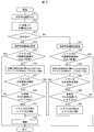
- FIG. 5 is a flowchart showing processing of the input apparatus 1 according to the present embodiment.
- (A) of FIG. 7 is a figure for demonstrating regarding the input invalid area
- the invalid area setting / confirming unit 45 further confirms whether the user input acquired by the touch panel 3 is acquired in the left invalid area AL (S17).
- the invalid area setting / confirming unit 45 determines that the user input acquired in the left invalid area AL is It is confirmed whether or not the user input is continuous from another area different from the left invalid area AL (S18).
- This “other area” refers to an input effective area where a valid user input can be acquired, and the touch position comparison unit 44 can change the effective area E according to the dominant hand. The same applies to “another area different from the right invalid area AR” described later.
- the invalid area setting / confirming unit 45 uses the user input acquired in the left invalid area AL as a valid user in the left invalid area AL. It is determined as an input, and is set as a drawing process target (S19). On the other hand, if it is determined that the user input is not continuous (NO in S18), it is determined that the user input acquired in the left invalid area AL is an invalid user input, and the touch position comparison unit 44 determines that the left side The user input acquired at the leftmost touch position excluding the invalid area AL is extracted as a valid user input. On the other hand, the invalid area setting / confirming unit 45 processes that there is no valid user input when only the information acquired in the left invalid area AL is obtained. Then, the process shown in FIG. 5 ends. In the case of NO in S17, drawing by the stylus pen 20 is started based on the valid user input extracted in the process of S16 (S20).
- the contact area P of the stylus pen 20 is determined as the effective area E through the process of S16. Subsequently, it is assumed that continuous user input using the stylus pen 20 is performed, the stylus pen 20 moves from the contact area P to the contact area Q, and a part of the contact area Q enters the left invalid area AL. In this case, since the user input in the contact area Q is determined as a continuous user input from the contact area P, it is determined as an effective user input. That is, the contact area Q is also maintained as the effective area E. In this case, the locus from the contact area P to the contact area Q is displayed on the display unit 2.
- the processing from S24 to S26 is the same as the processing from S17 to S19. That is, after the processing of S23, the invalid area setting / confirming unit 45 further confirms whether the user input acquired by the touch panel 3 is acquired in the right invalid area AR (S24). When the user input is acquired in the right invalid area AR (YES in S24), the invalid area setting / confirming unit 45 receives the user input acquired in the right invalid area AR from the input valid area. It is confirmed whether or not it is a continuous user input (S25). If it is a continuous user input (YES in S25), it is determined that the user input acquired in the right invalid area AR is also a valid user input in the right invalid area AR (S26).
- the touch position comparison unit 44 determines that the right invalid area AR The user input acquired at the rightmost touch position excluding is extracted as a valid user input.
- the invalid area setting / confirming unit 45 is only acquired in the right invalid area AR, the invalid area setting / confirming unit 45 processes that there is no valid user input. If NO in S24, drawing with the stylus pen 20 is started based on the valid user input extracted in the process of S23 (S20).
- the invalid area setting / confirming unit 45 receives the user input acquired in the set invalid input area as a continuous user input from another area (input valid area) different from the invalid input area. If acquired, the user input in the input invalid area is maintained as a valid user input. Therefore, user input that has a high probability of being valid user input even in the invalid input area (for example, user input indicating the continuation of handwritten input) can be acquired as valid user input, further improving user convenience. it can.
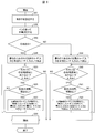
- FIG. 6 is a flowchart showing processing of the input device 1 according to the modification.
- FIG. 7B is a diagram for explaining the input invalid area at the time of the processing. Note that the processing of S31 to S34, S38 and S39 in FIG. 6 is the same as S1 to S3, S6, S7 and S10 of FIG. In the process of FIG. 6, since an invalid input area having a width according to the initial setting value is not set, effective user input is extracted for the entire touch panel 3 based on the determination result in S33.
- the invalid area setting / confirming unit 45 determines whether or not the touch position of the user input determined as the valid user input in S34 exists in the left end area L of the touch panel 3 when the touch panel 3 is visually recognized.
- the “left end area L” of the present embodiment may be an area having the same size as the input invalid area described above, for example. The same applies to a “right end region R” to be described later. If it is determined that the touch position of the user input exists in the left end area L (YES in S35), the invalid area setting / confirming unit 45 is at a position where the touch positions of the user input are considered to be the same for a predetermined time. It is confirmed whether or not there is no movement at the touch position (S36).
- the touch position hardly moves near the left end region (when gripping with the left hand) or near the right end region (when gripping with the right hand) of the input device. For this reason, it is possible to determine whether the user input is from the stylus pen 20 or the dominant hand or the handle by checking whether or not the touch position has been moved for a predetermined time.
- the predetermined time may be a time when the determination is possible.
- the stylus pen 20 is in contact with the display surface of the display unit 2 and the contact position is determined as the initial position of handwriting input. It is sufficient that the time is set to be larger than the time required for.
- the invalid area setting / confirmation unit 45 invalidates the user input of the left end area L and confirms that there has been no movement for a predetermined time.
- the touch position comparison unit 44 is notified. As shown in FIG. 7B, the invalid area setting / confirming unit 45 invalidates the user input in the contact area DA of the thumb of the handle (left hand), for example.
- the touch position comparison unit 44 when viewing the touch panel 3 among a plurality of user inputs other than the user input invalidated by the invalid area setting / confirmation unit 45, the touch position present on the leftmost side
- the user input is extracted again as a valid user input (S37). This is because the valid user input extracted before this processing is the user input by the hand (left hand), and the invalid area setting / confirming unit 45 invalidates the user input. Then, the process returns to S35.
- the processing after S39 is the same as the processing from S35 to S37. That is, the invalid area setting / confirming unit 45 confirms whether or not the touch position of the user input determined as the valid user input in S39 exists in the right end area R of the touch panel 3 when the touch panel 3 is visually recognized. (S40). When the touch position of the user input exists in the right end region R (YES in S40), the invalid region setting / confirming unit 45 confirms whether or not there is no movement at the touch position for a predetermined time (S41). . When there is no movement for a predetermined time (YES in S41), the invalid area setting / confirming unit 45 invalidates the user input of the right end area R, and the touch position comparing unit 44 is invalidated by the user. Among the plurality of user inputs other than the input, when the touch panel 3 is visually recognized, the user input existing on the rightmost side is extracted again as an effective user input (S42). Then, the process returns to S39.
- the invalid area setting / confirming unit 45 invalidates the user input when the touch panel 3 acquires the user input from the position considered to be the same for a predetermined time in the left end area L or the right end area R. I have to. That is, in view of the general usage of the input device, when a user input that does not move for a predetermined time is acquired in the left end region L, it is determined that the user is holding with the left hand (the left hand is the handle). . Similarly, in the right end region R, when a user input that has not moved for a predetermined time is acquired, it is determined that the user is holding with the right hand. Then, the user input by the handle is invalidated so that the user input by the dominant hand can be appropriately acquired as a valid user input. Thereby, it is possible to prevent the input device 1 from erroneously detecting a user input by the handle, that is, a user input not intended by the user. In addition, the input invalid area can be dynamically determined according to the contact position of the hand.
- the input device 1 is a case where the user input is present in the left end region L or the right end region R in addition to the case where there is no user input determined to be valid in the left end region L or the right end region R.
- the touch detection surface of the touch panel 3 other than the contact area of the hand can be used effectively. Further, it is determined whether or not the input is a user input by a handle, and the user input is invalidated based on the determination result.
- the contact area DA shown in FIG. 7B is not necessarily an input invalid area.
- the above-described initial setting value may be changed so as to include the contact area DA. That is, an input invalid area having a predetermined width from the left end or the right end of the touch panel 3 including the contact area DA may be set.
- the dominant hand setting unit 41 performs the dominant hand setting according to the user's instruction (S1 in FIG. 4, S11 in FIG. 5, and S31 in FIG. 6).
- the dominant hand setting unit 41 sets the dominant hand based on the touch position of the holding hand. More specifically, when the dominant hand setting unit 41 obtains a user input from a position regarded as the same for a predetermined time in the left end region L or the right end region R of the touch panel 3 when the touch panel 3 is visually recognized, It is determined that the detection target (for example, the user's finger) of the touch panel 3 that has performed the user input is the user's handle that holds the input device 1.
- the dominant hand setting unit 41 sets the user's dominant hand based on the determination result (whether the handle is the right hand or the left hand). For example, in the left end region L, when a user input is acquired from a position regarded as the same for a predetermined time, it is determined that the hand is the left hand and the dominant hand is the right hand. Similarly, in the right end region R, when a user input is acquired from a position regarded as the same for a predetermined time, it is determined that the holding hand is the right hand and the dominant hand is the left hand.
- FIG. 8 is a flowchart showing processing of the input apparatus 1 according to the present embodiment.
- the touch panel 3 acquires a user input by the hand, and the touch position detection unit 43 detects the acquisition position (touch position). Then, the dominant hand setting unit 41 checks whether or not the touch position exists in the left end region L (S51). If it is determined that it exists in the left end region L (YES in S51), the dominant hand setting unit 41 is in a position where the touch position of the user input is considered to be the same for a predetermined time (that is, the touch position moves). (S52). The definition of the predetermined time is the same as in the second embodiment. If it is determined that there is no movement at the touch position for a predetermined time (YES in S52), the dominant hand determination unit 42 determines that the hand is the left hand. That is, it is determined that the dominant hand is the right hand, and the right hand is set as the dominant hand (S53).
- the dominant hand setting unit 41 checks whether or not there is no movement at the touch position for a predetermined time (S55). When it is determined that there is no movement at the touch position for a predetermined time (YES in S55), the dominant hand determination unit 42 determines that the hand is the right hand and the dominant hand is the left hand, and sets the left hand as the dominant hand (S56). ).
- the dominant hand setting unit 41 requests the user to set the dominant hand by displaying the dominant hand selection screen as in the first embodiment (S57). Through this process, even if the dominant hand setting based on the hand holding determination cannot be performed, the user can perform the dominant hand setting. In addition, you may return to the process of S51 instead of the process of S57.
- the input device 1 determines the grip state and sets the user's dominant hand based on the determination result. it can. Therefore, even if the user does not intentionally set the dominant hand, the dominant hand is automatically set, so that the convenience for the user can be further improved. Especially in situations where the input device 1 is often held and used, user convenience can be improved.
- the control block of the input device 1 may be realized by a logic circuit (hardware) formed in an integrated circuit (IC chip) or the like, or using a CPU (Central Processing Unit). It may be realized by software.
- the input device 1 includes a CPU that executes instructions of a program that is software that implements each function, a ROM (Read Only Memory) in which the program and various data are recorded so as to be readable by a computer (or CPU), or A storage device (these are referred to as “recording media”), a RAM (Random Access Memory) for expanding the program, and the like are provided.
- recording media these are referred to as “recording media”
- RAM Random Access Memory
- the objective of this invention is achieved when a computer (or CPU) reads the said program from the said recording medium and runs it.
- the recording medium a “non-temporary tangible medium” such as a tape, a disk, a card, a semiconductor memory, a programmable logic circuit, or the like can be used.
- the program may be supplied to the computer via an arbitrary transmission medium (such as a communication network or a broadcast wave) that can transmit the program.
- a transmission medium such as a communication network or a broadcast wave
- the present invention can also be realized in the form of a data signal embedded in a carrier wave in which the program is embodied by electronic transmission.
- the input device (1) is an input device including a planar member (touch panel 3) that can simultaneously acquire a plurality of user inputs, and a dominant hand determination unit that determines a user's dominant hand ( 42) and an area (effective area E) to be extracted as an effective user input among a plurality of user inputs obtained by the dominant hand acquired by the planar member according to the dominant hand determined by the dominant hand determination unit. And an effective area changing unit (touch position comparing unit 44).
- the input device can acquire user input intended by the user according to the dominant hand, and can invalidate user input not intended by the user. Therefore, for example, it is possible to avoid erroneous detection of user input (input by so-called “hand”) that should not be acquired as handwritten input, and to appropriately acquire user input necessary as handwritten input. Become.
- the effective area changing unit has determined that the dominant hand is a right hand by the dominant hand determining unit (42).
- the planar member In the case, among the plurality of user inputs by the dominant hand acquired by the planar member (touch panel 3), at least one of the user inputs acquired relatively on the left side when the planar member is viewed,
- the dominant hand is extracted as the effective user input and the dominant hand determination unit determines that the dominant hand is a left hand
- the planar member of the plurality of user inputs obtained by the dominant hand is acquired by the planar member. It is preferable to extract at least one of the user inputs acquired on the relatively right side when visually recognized as the effective user input.
- the input device validates at least one of the user inputs acquired on the relatively left side among the plurality of user inputs by the right hand. As user input.
- the determined dominant hand is the left hand
- at least one of the user inputs acquired on the relatively right side among the plurality of user inputs by the left hand is extracted as an effective user input.
- the user places the vicinity of the little finger of the right hand on the planar member, and performs handwriting input using the stylus pen gripped by the right hand or the index finger of the right hand.
- the stylus pen or index finger is the user input acquired on the relatively left side.
- the stylus pen or the index finger is the user input acquired on the relatively right side. Therefore, in any case, the stylus pen or the index finger can be extracted as an effective user input.
- the user input intended by the user can be appropriately acquired as an effective user input.
- the input device (1) according to aspect 3 of the present invention is the aspect 1 or 2, in which the left end region (L) of the planar member when the planar member (touch panel 3) is visually recognized, or the planar member. It is preferable that an input invalid area (left invalid area AL, right invalid area AR) that invalidates the user input acquired by the planar member is set in the right end area (R).
- the input device may erroneously detect a user input (a user input not intended by the user) by a handle that is not a dominant hand as a valid user input.
- the above-described erroneous detection can be prevented.
- the input device (1) according to aspect 4 of the present invention is the aspect 1 or 2, in which the left end region (L) of the planar member when the planar member (touch panel 3) is visually recognized, or the planar member.
- an invalid setting unit invalid region setting / confirming unit that invalidates the user input 45).
- the input device invalidates the user input when acquiring the user input from the position considered to be the same for a predetermined time in the left end region or the right end region.
- the input device invalidates the user input when acquiring the user input from the position considered to be the same for a predetermined time in the left end region or the right end region.
- the input device (1) may be realized by a computer.
- an input that causes the input device to be realized by the computer by operating the computer as each unit included in the input device.
- An apparatus input control program and a computer-readable recording medium on which the apparatus input control program is recorded also fall within the scope of the present invention.
- a recording apparatus can be realized on a computer by realizing the above-described units with a computer.
- the input control program read from the recording medium can be realized on a general-purpose computer.
- the present invention is used for an input device including a planar member that can simultaneously acquire a plurality of user inputs, and can be suitably used particularly for an input device including a touch panel that can acquire handwritten input with a stylus pen or the like.
- Input device 3 Touch panel (planar member) 42 Handedness determination unit 44 Touch position comparison unit (effective area change unit) 45 Invalid area setting / confirmation part (invalid setting part) E Effective area (area) L Left end area R Right end area AL Left invalid area (input invalid area) AR Right invalid area (input invalid area)
Landscapes
- Engineering & Computer Science (AREA)
- General Engineering & Computer Science (AREA)
- Theoretical Computer Science (AREA)
- Human Computer Interaction (AREA)
- Physics & Mathematics (AREA)
- General Physics & Mathematics (AREA)
- User Interface Of Digital Computer (AREA)
Abstract
利き手に応じて、ユーザが意図する入力を取得可能な入力装置等を提供する。タッチパネル(3)を備えている入力装置(1)は、ユーザの利き手を判断する利き手判断部(42)と、判断された利き手に応じて、タッチパネル(3)が取得した当該利き手による複数のユーザ入力のうち、有効なユーザ入力として抽出する有効領域(E)を変更するタッチ位置比較部(44)と、を備えている。
Description
本発明は、複数のユーザ入力を同時に取得可能な入力装置に関する。
従来から、スタイラスペンやマウス、ユーザの指先などの指示体を用いた手書き入力を受け付け、当該手書き入力の軌跡(筆跡)から、ユーザが書いた(描いた)文字または図形を認識する入力装置が知られている。また、手書き入力の軌跡以外のユーザ入力を無効とする入力装置が知られている。そのような入力装置の一例が、例えば特許文献1~3に開示されている。
特許文献1では、検出領域上に掌を置いた場合には、当該掌に起因した接触を拒絶する技術が開示されている。すなわち、特許文献1の技術では、スタイラスペンによるユーザ入力と、指接触によるユーザ入力とが検出した場合には、前者の入力を優先的に受け付けている。また、特許文献2では、手書き入力を受け付ける手書き領域と、タッチパネルへのタッチが行われても手書き入力として受け付けないお手付き可能領域とが設定される技術が開示されている。また、特許文献3には、手書き入力枠ごとに、ペンを持つ手がタブレットに接触するために行われる誤入力を無効とする入力無効領域を設定する技術が開示されている。
しかしながら、特許文献1では、ユーザの利き手に応じて、掌に起因した接触を拒絶したり、スタイラスペンによるユーザ入力を優先的に取得したりするものではない。また、特許文献2および3の技術では、お手付き可能領域または入力無効領域の設定を前提として、画面上に接触した利き手によるユーザ入力を無効にしている。すなわち、これらの技術では、当該領域を設定することなく、取得した複数のユーザ入力の中から、無効にするユーザ入力を決定するものではない。
したがって、特許文献1~3の技術では、複数のユーザ入力を取得したときに、上記領域を設定することなく、ユーザの利き手に応じて、その複数のユーザ入力のうちのどのユーザ入力を無効とするか(または、有効とするか)を決定しているわけではない。そのため、上記領域を設定しない場合には、ユーザの利き手に応じて、ユーザが意図するユーザ入力を取得できない可能性があった。
本願は、上記問題に鑑みてなされたものであり、その目的は、利き手に応じて、ユーザが意図するユーザ入力を取得可能な入力装置等を提供することを目的とする。
上記の課題を解決するために、本発明の一態様に係る入力装置は、複数のユーザ入力を同時に取得可能な面状部材を備えている入力装置であって、ユーザの利き手を判断する利き手判断部と、上記利き手判断部によって判断された上記利き手に応じて、上記面状部材が取得した当該利き手による複数のユーザ入力のうち、有効なユーザ入力として抽出する領域を変更する有効領域変更部と、を備えている。
本発明の一態様によれば、利き手に応じて、ユーザが意図するユーザ入力を取得することができるという効果を奏する。
〔実施形態1〕
以下、本発明の一実施形態について、図1~図4を参照しながら、詳細に説明する。まず、図2を用いて、入力装置(入力端末)1の概略構成について説明する。図2は、入力装置1の概略構成を示す図である。
以下、本発明の一実施形態について、図1~図4を参照しながら、詳細に説明する。まず、図2を用いて、入力装置(入力端末)1の概略構成について説明する。図2は、入力装置1の概略構成を示す図である。
図2に示すように、入力装置1は、表示部2およびタッチパネル(面状部材)3を備えた板状の筐体であり、例えばタブレット端末である。表示部2は、例えば、入力装置1に装備されている各種機能(アプリケーションソフト)が実行されることに起因した画像等の各種画像を表示するものである。表示部2としては、例えばLCD(Liquid crystal display:液晶ディスプレイ)が用いられる。タッチパネル3は、図2の(a)に示すようにスタイラスペン20や、図2の(b)に示すようにユーザの指(例えば人差し指)等の接触(または接近)を検知することにより、ユーザ入力を取得するものである。また、タッチパネル3は、複数のユーザ入力を同時に取得(多点検知)可能である。タッチパネル3は、例えば、表示部2に積層された静電容量方式のタッチパネルである。カメラ部6は、被写体を撮像する撮像部である。これらの表示部2、タッチパネル3およびカメラ部6は、後述の制御部4によって制御される。
入力装置1は、例えば、スタイラスペン20または指の軌跡を、ユーザ入力としてタッチパネル3が取得(検知)し、その取得した軌跡に沿って、当該軌跡を視認可能な画像を表示部2に表示させる。これにより、手書き入力の機能が実現する。すなわち、入力装置1では、アプリケーションソフトとして、例えば手書き入力ソフトが実行される。
なお、入力装置1は、例えばスマートフォン等の携帯型情報端末であってもよい。また、携帯型情報端末でなくてもよく、少なくとも表示部2とタッチパネル3とを備えている種々の情報端末により実現可能である。入力装置1は、机等の上に置いて使用可能な情報端末等、ユーザ入力時に利き手の一部を表示部2の表示面上に付いて入力する可能性がある情報端末に有効に適用できる。また、タッチパネル3は静電容量方式でなくてもよく、タッチパネル3の代わりに光学式センサを用いてもよい。すなわち、タッチパネル3は、検知対象物の多点検知が可能な構成であればよい。
次に、図1および図3を用いて、入力装置1の具体的構成について説明する。図1は、入力装置1の具体的構成を示すブロック図である。図3は、有効なユーザ入力の抽出について説明するための図であり、(a)は利き手が右手の場合、(b)は利き手が左手の場合である。
図1に示すように、入力装置1は、表示部2、タッチパネル3、制御部4および記憶部5を備える。制御部4は、入力装置1を統括的に制御するものであり、主として、利き手設定部41、利き手判断部42、タッチ位置検出部43、タッチ位置比較部(有効領域変更部)44、無効領域設定/確認部(無効設定部)45、および表示制御部46を備えている。また、記憶部5は、制御部4が実行する各種の制御プログラム等を記憶するものである。記憶部5は、例えばハードディスク、フラッシュメモリなどの不揮発性の記憶装置によって構成される。
利き手設定部41は、ユーザの利き手を設定する。例えばスタイラスペン20の持ち手など、有効なユーザ入力として取得すべきユーザ入力を行う利き手がいずれの手であるのかを、入力装置1、または、入力装置1の、利き手設定が必要なアプリケーション(例えば手書き入力ソフト)に設定する。そして、設定された利き手を示す利き手情報を利き手判断部42に送信する。本実施形態では、利き手設定部41は、例えば、利き手設定をユーザに行わせるための利き手選択画面の表示指示を、表示制御部46に送信する。表示制御部46は、当該表示指示を受けると、利き手選択画面を記憶部5から読み出し、表示部2に表示させる。ユーザは、自身の利き手(右手か左手か)を選択する。利き手設定部41は、タッチ位置検出部43から、タッチパネル3が取得したユーザ入力のタッチ位置(検出結果)を受信すると、そのタッチ位置から、利き手としていずれの手が選択されたのかを判断し、選択された手を利き手として設定する。
利き手判断部42は、利き手設定部41から受信した利き手情報に基づき、ユーザの利き手を判断し、判断結果をタッチ位置比較部44および無効領域設定/確認部45に送信する。
タッチ位置検出部43は、タッチパネル3が取得したユーザ入力のタッチ位置を検出する。複数のユーザ入力を同時に取得した場合には、各ユーザ入力のタッチ位置をそれぞれ検出する。そして、利き手設定時に取得した検出結果については利き手設定部41へ、それ以外(例えば手書き入力時)に取得した検出結果についてはタッチ位置比較部44および無効領域設定/確認部45へ、それぞれ送信する。
タッチ位置比較部44は、利き手判断部42によって判断された利き手に応じて、タッチパネル3が取得した当該利き手による複数のユーザ入力のうち、有効なユーザ入力として抽出する有効領域(領域)Cを変更する(切り替える)。表示部2の表示面に手を付いて手書き入力を行う場合、図3の(a)に示すように、利き手が右手であれば、当該表示面には、右手の小指付近とスタイラスペン20のペン先とが接触する。タッチパネル3は、これらが接触した領域である接触領域C(利き手による全体的な接触領域)において、上記利き手による複数のユーザ入力を取得する。タッチ位置比較部44は、そのうちの一部を、有効なユーザ入力として抽出する有効領域Eとして決定する。
より具体的には、タッチ位置比較部44は、利き手判断部42から受信した判断結果が、利き手が右手であることを示している場合には、右手による複数のユーザ入力のタッチ位置を比較する。そして、当該複数のユーザ入力のうち、タッチパネル3を視認したときの相対的に左側において取得されたユーザ入力の少なくとも1つを、有効なユーザ入力として抽出する。図3の(a)では、複数のユーザ入力を取得する接触領域Cのうち、相対的に左側において取得されたユーザ入力を含む有効領域Eとして決定する。すなわち、有効領域E内のユーザ入力を、有効なユーザ入力として抽出する。同様に、タッチ位置比較部44は、上記判断結果が、利き手が左手であることを示している場合には、左手による複数のユーザ入力のうち、タッチパネル3を視認したときの相対的に右側において取得されたユーザ入力の少なくとも1つを、有効なユーザ入力として抽出する。図3の(b)では、複数のユーザ入力を取得する接触領域Cのうち、相対的に右側において取得されたユーザ入力を含む有効領域Eとして決定する。
一般には、表示部2の表示面に手を付いてユーザ入力を行う場合、利き手が右手であれば、スタイラスペン20のペン先、または利き手の人差し指の先端は、小指付近よりも、タッチパネル3を視認したときの左側の領域(持ち手(ユーザ入力を行わない、利き手でない方の手指)側)において、当該表示面と接触する。一方、利き手が左手であれば、上記ペン先または人差し指の先端は、小指付近よりも、タッチパネル3を視認したときの右側の領域(持ち手側)において、上記表示面と接触する。したがって、利き手が右手のときには、タッチパネル3を視認したときの相対的に左側のユーザ入力を、利き手が左手のときには、タッチパネル3を視認したときの相対的に右側のユーザ入力を、それぞれ有効なユーザ入力として取得することにより、スタイラスペン20または利き手の人差し指によるユーザ入力を適切に取得することが可能となる。すなわち、利き手に応じて、ユーザが意図するユーザ入力を、有効なユーザ入力として適切に取得できる。
なお、利き手による複数のユーザ入力のうち、利き手が右手であれば、タッチパネル3を視認したときの最も左側のユーザ入力を、利き手が左手であれば、タッチパネル3を視認したときの最も右側のユーザ入力を、それぞれ有効なユーザ入力としてもよい。ただし、スタイラスペン20のペン先が太い場合、または指入力の場合で、かつ、そのペン先および指が接触する接触領域に合わせた太い軌跡の描画を可能とする場合には、最も左側または最も右側を含む接触領域を有効領域Eとして、当該有効領域E内の複数のユーザ入力を全て有効なユーザ入力として抽出することが好ましい。これにより、様々な入力態様に対応した描画状態を、忠実に表示部2に表示させることができる。この有効領域Eの大きさは、接触領域と必ずしも一致している必要はなく、ユーザが意図する描画(ペン先または指の軌跡に沿った画像表示)が行えるように設定されていればよい。また、図3において、各領域は、説明のために簡略化して図示されている。例えば、接触領域Cのうち、小指付近の接触領域は、見やすさを考慮して、矩形状に図示されている。また、接触領域Cのうち、ペン先の接触領域(有効領域E)も同様に、ペン先よりも大きな円形状に図示されている。
無効領域設定/確認部45は、タッチパネル3が取得したユーザ入力を無効とする入力無効領域(不感領域)を設定する。また、その入力無効領域にユーザ入力があったか否かを確認し、当該ユーザ入力の有効/無効を判断する。無効領域設定/確認部45は、利き手判断部42から受信した判断結果に応じて、タッチパネル3に対して入力無効領域を設定する。すなわち、入力無効領域を設定した場合、当該入力無効領域に含まれるタッチパネル3の電極で取得された、タッチまたはタップとしてのユーザ入力を無効にする。スタイラスペン20を使用している場合であれば、入力装置1は、設定した入力無効領域においては、スタイラスペン20によるユーザ入力(ペン入力)とは認識しないともいえる。
無効領域設定/確認部45は、利き手が右手である場合には、例えば図3の(a)に示すように、タッチパネル3を視認したときのタッチパネル3の左端領域Lに、入力無効領域として左側無効領域ALを設定する。一方、利き手が左手である場合には、例えば図3の(b)に示すように、タッチパネル3を視認したときのタッチパネル3の右端領域Rに、入力無効領域として右側無効領域ARを設定する。すなわち、表示部2の、利き手と反対側の表示面の端部(画面端)近傍の少なくとも一部の領域を、入力無効領域として設定する。入力無効領域が存在しない場合には、利き手が右手であれば、持ち手となる左手の一部(例えば親指)が表示部2の表示面(左端領域L付近)に接触する可能性がある。同様に、利き手が左手であれば、持ち手となる右手の一部が上記表示面(右端領域R付近)に接触する可能性がある。タッチ位置比較部44は、上述のように、利き手が右手であれば相対的に左側のユーザ入力を、利き手が左手であれば相対的に左側のユーザ入力を、それぞれ有効なユーザ入力として抽出する。そのため、持ち手の一部が上記表示面に接触している場合には、当該一部によるユーザ入力を有効なユーザ入力として誤検出してしまう可能性がある。そこで、無効領域設定/確認部45が入力無効領域を設定することにより、このような誤検出を未然に防ぐことができる。換言すれば、スタイラスペン20によるユーザ入力を適切に取得できる。また、入力無効領域を設定することにより、特に、入力装置1を把持して使用する場合に有効である。すなわち、入力装置1を手で持ちながら、手書き入力を行う場合でも、ユーザの意図するユーザ入力(例えば、スタイラスペン20によるユーザ入力)を取得できる。
本実施形態では、表示部2の表示面(またはタッチパネル3のタッチ検出面)の長手方向における画素数が1280ピクセル(入力装置1の長手方向の長さが約10インチ)である。そして、そのときの左側無効領域ALおよび右側無効領域ARの幅は、それぞれ5ピクセル分の幅(表示面の画面幅(長手方向の長さ)に対して約0.4%程度の幅)に設定されている。これに限らず、例えば、この幅は、上記画面幅の1%程度の長さに設定されていてもよい。
なお、上記幅は、入力装置1の筐体幅(ベゼル幅)W(図2の(a)参照)にも依存する。すなわち、筐体幅Wが広ければ、持ち手が表示部2の表示面に触れる可能性が低く、触れても持ち手のほんの一部が触れる程度である可能性が高い。そのため、筐体幅Wが広い場合には、上記幅は狭くてもよい。一方、筐体幅Wが狭ければ(例えば、狭額縁の入力装置の場合)、持ち手が上記表示面に触れ、その接触領域も大きくなる可能性が高い。そのため、筐体幅Wが狭い場合には、上記幅は、持ち手が触れると想定される範囲を含むように広めに設定されていることが好ましい。すなわち、上記幅は、持ち手によるユーザ入力が誤って検知されることを防ぐことが可能なように設定されていればよい。また、無効領域設定/確認部45は、記憶部5に予め記憶された初期設定値に従って上記幅を決定し、入力無効領域を設定しているが、ユーザの指示により上記初期設定値を変更してもよい。また、ユーザ指示により、入力無効領域を設定するか否かを決定してもよい。
表示制御部46は、表示部2に各種画像を表示させる。例えば、上記利き手選択画面や、手書き入力時に取得した、スタイラスペン20または指の軌跡を示す画像を、表示部2に表示させる。
次に、図3および図4を用いて、入力装置1における処理の流れについて説明する。図4は、入力装置1の処理を示すフローチャートである。図4では、スタイラスペン20を用いて手書き入力が行われる場合の処理の一例について説明する。
利き手設定部41は、ユーザの指示に従って、当該ユーザの利き手を設定する(S1)。ユーザの利き手設定が完了すると、表示制御部46は、手書き入力の実行が可能な手書き入力画面を、表示部2に表示させる。そして、ユーザは、手書き入力画面に対して、スタイラスペン20を用いた手書きを開始する(S2)。
S2の処理において、タッチパネル3がユーザ入力を取得したときに、利き手判断部42は、ユーザの利き手が右手か左手か(ユーザが右利きか左利きか)を判断する(S3)。利き手が右手であると判断された場合(S3でYES)、無効領域設定/確認部45は、左側無効領域ALを設定し(S4)、S2の処理において取得したユーザ入力が、左側無効領域AL内のみで取得されたものか否かを確認する(S5)。すなわち、そのユーザ入力を取得したタッチ位置が左側無効領域AL内のみに存在するか否かを確認する。そして、無効領域設定/確認部45は、そのユーザ入力が左側無効領域AL内のみで取得されたものではないと判断した場合(S5でNO)、その旨をタッチ位置比較部44に通知する。タッチ位置比較部44は、当該通知を受けると、複数のユーザ入力のタッチ位置をそれぞれ比較し、タッチパネル3を視認したとき、左側無効領域ALを除く最も左に存在するタッチ位置において取得されたユーザ入力を、有効なユーザ入力として抽出する(S6)。すなわち、有効なユーザ入力を抽出する有効領域Eを決定する。そして、表示制御部46は、タッチ位置比較部44が抽出した有効なユーザ入力(タッチ位置比較部44が決定した有効領域E内のユーザ入力)を手書き入力画面に反映させ、表示部2に表示させる。これにより、スタイラスペン20による描画(手書き入力)が開始される(S7)。そして、表示制御部46は、有効領域Eの軌跡を表示部2に表示させる。
一方、S3において、利き手が左手であると判断された場合(S3でNO)、無効領域設定/確認部45は、右側無効領域ARを設定し(S8)、S2の処理において取得したユーザ入力が、右側無効領域AR内のみで取得されたものか否かを確認する(S9)。そして、そのユーザ入力が右側無効領域AR内のみで取得されたものではないと判断した場合(S9でNO)、その旨をタッチ位置比較部44に通知する。タッチ位置比較部44は、当該通知を受けると、複数のユーザ入力に対応するタッチ位置のうち、タッチパネル3を視認したとき、右側無効領域ARを除く最も右に存在するタッチ位置におけるユーザ入力を、有効なユーザ入力として抽出する(S10)。そして、S10の処理後、スタイラスペン20による描画が開始される(S7)。
また、S5でYES、またはS9でYESの場合、即ち検出されたユーザ入力が入力無効領域内で取得されたもののみである場合には、有効なユーザ入力がないものとして、図4に示す処理が終了する。これは、タッチまたはタップとしてのユーザ入力を入力無効領域にて取得した場合、持ち手によるユーザ入力の可能性があるためである。
なお、S3の判断は、S2の処理後でなくてもよく、S1の処理後(利き手が設定された直後)に行われてもよい。また、S6では最も左のタッチ位置、S10では最も右のタッチ位置におけるユーザ入力(すなわち、1座標におけるユーザ入力)を、それぞれ有効なユーザ入力と判断しているが、上述したように、スタイラスペン20等の検知対象物が接触している接触領域を有効領域Eとし、その有効領域E内の複数のユーザ入力を有効なユーザ入力としてもよい。また、一般に、タッチパネル3が取得する、スタイラスペン20の検出による静電容量値と、指の検出による静電容量値は異なる。そこで、その違いを利用して、スタイラスペン20によるユーザ入力の場合には、左側無効領域AL内または右側無効領域AR内でのタッチまたはタップであっても、ユーザ入力を有効と判断してもよい。また、S1の処理では、例えば利き手選択画面に対するユーザ入力に従って、利き手が設定されているが、これに限らず、例えば、持ち手がいずれの手であるかを判断することで、利き手が設定されてもよい。当該例については、実施形態3にて説明する。
以上のように、本実施形態の入力装置1は、利き手判断部42によって判断された利き手に応じて、タッチパネル3が取得した当該利き手による複数のユーザ入力のうち、有効なユーザ入力として抽出する有効領域Eを変更する。これにより、利き手に応じて、ユーザが意図するユーザ入力を取得することが可能となるとともに、ユーザが意図しないユーザ入力を無効にすることができる。例えば、入力装置1は、表示部2の表示面に利き手の掌全体を置いた場合(手をべた置きした場合)でも、小指付近等の利き手の一部分が付いた場合でも、スタイラスペン20のペン先部分、または利き手の人差し指の先端部分の軌跡に沿って描画できる。すなわち、表示部2の表示面に利き手を付けながら手書き入力を行うときに、ユーザが意図しないユーザ入力を取得してしまい、ユーザが意図しない描画がなされてしまうことを防止できる。
ここで、本願の発明者は、利き手設定を行わずに、スタイラスペンによるユーザ入力を取得する構成についても検討した。ユーザの利便性を考慮すれば、ユーザに利き手設定を行わせずに、上記ユーザ入力を適切に取得できる方が好ましいためである。例えば、複数のユーザ入力のうち、タッチパネルを視認したときの、タッチパネルの上側(図2の(a)でいえばカメラ部6に近い位置側)において取得したユーザ入力を、スタイラスペンによるユーザ入力として判断する構成が挙げられる。すなわち、この構成では、利き手設定を行わず、上記ユーザ入力のタッチ位置をタッチパネルのY座標(図2の(a)でいえば、入力装置1の短手方向の座標)で判断する。この構成の場合、利き手の小指付近の接触位置よりも上側において、スタイラスペンのペン先が表示面に接触している場合には、スタイラスペンによるユーザ入力を取得できる。しかし、スタイラスペンを用いた手書き入力方法は、ユーザによって異なる。例えば、小指付近の接触位置よりも下側(図2の(a)でいえばカメラ部6から遠い位置側)において、スタイラスペンのペン先が表示面に接触するように、手書き入力を行うユーザも存在する。この場合、小指付近の接触位置がスタイラスペンのペン先の接触位置よりも上側にあるため、スタイラスペンによるユーザ入力を取得できない。
一方、例えば利き手が右手の場合には、ユーザによらず、右手の小指付近よりも、タッチパネルを視認したときのタッチパネルの左側において、ペン先が表示面に接触する。利き手が左手の場合も同様、ユーザによらず、左手の小指付近よりも、タッチパネルを視認したときのタッチパネルの右側においてペン先が表示面に接触する。そのため、本願の発明者は、スタイラスペンによるユーザ入力(有効なユーザ入力)を適切に抽出するために、ユーザの利き手の判断結果を用いた方が、手書き入力においてユーザの利便性を向上させることができるという結論に至った。すなわち、本願の発明者は、ユーザの利便性を向上させるために、入力装置において、あえてユーザの利き手判断を行い、その判断結果に基づいて有効なユーザ入力を抽出する必要があることを見出した。
なお、特許文献1の技術は、上述したように、利き手に応じたスタイラスペンによるユーザ入力の取得を行うものではない。また、特許文献1の技術では、掌等の接触面積が広いユーザ入力を検知した場合に、その接触を「お手付き」とみなし無視することにより、「お手付き」による入力誤検出を除去している。したがって、当該技術では、掌と認識できる程度の接触面積よりも小さい接触面積を有するユーザ入力を取得した場合には(小指のみの場合等)、当該ユーザ入力を除去できない可能性がある。その結果、タッチイベントを用いて描画する場合、スタイラスペン以外の接触部分に対する描画も行われてしまう可能性がある。すなわち、当該技術では、接触面積が狭い「お手付き」の場合、例えばスタイラスペンを把持した手の小指だけが表示面に接触するような場合には、「お手付き」による入力とスタイラスペンによる入力とを区別できない可能性がある。また、特許文献2の技術ではお手付き可能領域が手動で設定され、特許文献3の技術では、手書き入力枠に付随して入力無効領域が設定される。しかし、本実施形態では、お手付き可能領域または入力無効領域を設定することなく、ユーザが意図するユーザ入力を取得できる。なお、本実施形態において入力無効領域として設定されるのは表示部2の画面端であり、特許文献3の技術のように手書き入力枠ごとに設定されるものではない。
〔実施形態2〕
本発明の他の実施形態について、図5~図7に基づいて説明すれば、以下のとおりである。なお、説明の便宜上、前記実施形態にて説明した部材と同じ機能を有する部材については、同じ符号を付記し、その説明を省略する。
本発明の他の実施形態について、図5~図7に基づいて説明すれば、以下のとおりである。なお、説明の便宜上、前記実施形態にて説明した部材と同じ機能を有する部材については、同じ符号を付記し、その説明を省略する。
実施形態1では、利き手に応じて、タッチパネル3の端部に帯状の入力無効領域(左側無効領域ALまたは右側無効領域AR)を設定し、タッチ位置が入力無効領域内に存在する場合、当該タッチ位置での入力を無効にしている。本実施形態では、実施形態1における入力無効領域の設定処理、または入力無効領域におけるユーザ入力の無効判断処理とは異なる処理について説明する。
まず、実施形態1のように、入力無効領域内のユーザ入力の全てを無効と判断する必要は必ずしもない。図5および図7を用いて、入力無効領域内のユーザ入力の全てを無効と判断しない場合の、入力装置1の処理の流れについて説明する。図5は、本実施形態に係る入力装置1の処理を示すフローチャートである。図7の(a)は、当該処理時の入力無効領域に関して説明するための図である。なお、図5のS11~S16、S20~S23の処理は、それぞれ図4のS1~S10と同様の処理であるため、その説明を省略する。
図5のS16の処理後、無効領域設定/確認部45は、さらにタッチパネル3が取得したユーザ入力が、左側無効領域AL内で取得されたものか否かを確認する(S17)。そして、そのユーザ入力が左側無効領域AL内で取得されたものであると判断した場合(S17でYES)、無効領域設定/確認部45は、左側無効領域AL内において取得されたユーザ入力が、左側無効領域ALとは異なる他の領域からの連続的なユーザ入力であるか否かを確認する(S18)。この「他の領域」とは、有効なユーザ入力を取得可能な入力有効領域であって、タッチ位置比較部44が、利き手に応じて、有効領域Eを変更可能な領域を指す。後述の「右側無効領域ARとは異なる他の領域」も同様である。連続的なユーザ入力であると判断した場合には(S18でYES)、無効領域設定/確認部45は、左側無効領域ALで取得されたユーザ入力を、当該左側無効領域ALにおいても有効なユーザ入力と判断し、描画処理の対象とする(S19)。一方、連続的なユーザ入力でないと判断した場合には(S18でNO)、左側無効領域ALで取得されたユーザ入力を無効なユーザ入力であると判断するとともに、タッチ位置比較部44は、左側無効領域ALを除く最も左に存在するタッチ位置において取得されたユーザ入力を有効なユーザ入力として抽出する。一方、無効領域設定/確認部45は、左側無効領域AL内で取得されたもののみである場合には、有効なユーザ入力がないとものとして処理する。そして、図5に示す処理が終了する。なお、S17でNOの場合には、S16の処理で抽出した有効なユーザ入力に基づいて、スタイラスペン20による描画が開始される(S20)。
例えば、図7の(a)の場合、S16の処理を経て、スタイラスペン20の接触領域Pが有効領域Eとして決定される。その後、スタイラスペン20を用いた連続的なユーザ入力が行われ、スタイラスペン20が接触領域Pから接触領域Qまで移動し、接触領域Qの一部が左側無効領域AL内に入り込んだとする。この場合、接触領域Qにおけるユーザ入力は、接触領域Pからの連続的なユーザ入力と判断されるため、有効なユーザ入力と判断される。すなわち、接触領域Qも有効領域Eとして維持される。そして、この場合、接触領域Pから接触領域Qまでの軌跡が表示部2に表示される。
S24~S26の処理も、S17~S19の処理と同様である。すなわち、S23の処理後、無効領域設定/確認部45は、さらにタッチパネル3が取得したユーザ入力が、右側無効領域AR内で取得されたものか否かを確認する(S24)。そして、そのユーザ入力が右側無効領域AR内で取得されたものである場合(S24でYES)、無効領域設定/確認部45は、右側無効領域AR内において取得されたユーザ入力が入力有効領域からの連続的なユーザ入力であるか否かを確認する(S25)。連続的なユーザ入力である場合には(S25でYES)、右側無効領域ARで取得されたユーザ入力を、当該右側無効領域ARにおいても有効なユーザ入力と判断する(S26)。一方、連続的なユーザ入力でない場合には(S25でNO)、右側無効領域ARで取得されたユーザ入力を無効なユーザ入力であると判断するとともに、タッチ位置比較部44は、右側無効領域ARを除く最も右に存在するタッチ位置において取得されたユーザ入力を有効なユーザ入力として抽出する。一方、無効領域設定/確認部45は、右側無効領域AR内で取得されたもののみである場合には、有効なユーザ入力がないものとして処理する。なお、S24でNOの場合には、S23の処理で抽出した有効なユーザ入力に基づいて、スタイラスペン20による描画が開始される(S20)。
このように、無効領域設定/確認部45は、設定した入力無効領域内において取得されたユーザ入力が、当該入力無効領域とは異なる他の領域(入力有効領域)からの連続的なユーザ入力として取得されている場合には、当該入力無効領域におけるユーザ入力を有効なユーザ入力として維持する。それゆえ、入力無効領域においても有効なユーザ入力である蓋然性が高いユーザ入力(例えば、手書き入力の続きを示すユーザ入力)については、有効なユーザ入力として取得できるので、ユーザの利便性をさらに向上できる。
次に、実施形態1のように、初期設定値に従った幅を有する入力無効領域が、利き手に応じて設定される必要は必ずしもない。図6および図7を用いて、初期設定値に従った幅を有する入力無効領域が設定されない場合の、入力装置1の処理の流れについて説明する。図6は、変形例に係る入力装置1の処理を示すフローチャートである。図7の(b)は、当該処理時の入力無効領域に関して説明するための図である。なお、図6のS31~S34、S38およびS39の処理は、それぞれ図4のS1~S3、S6、S7およびS10と同様の処理であるため、その説明を省略する。なお、図6の処理では、初期設定値に従った幅を有する入力無効領域が設定されないので、S33での判断結果に基づいて、タッチパネル3全体に対して有効なユーザ入力の抽出が行われる。
図6のS35では、無効領域設定/確認部45は、S34において有効なユーザ入力として判断されたユーザ入力のタッチ位置が、タッチパネル3を視認したときのタッチパネル3の左端領域Lに存在するか否かを確認する。本実施形態の「左端領域L」は、例えば、上述の入力無効領域と同じ大きさの領域であってもよい。後述の「右端領域R」についても同様である。上記ユーザ入力のタッチ位置が左端領域Lに存在すると判断した場合(S35でYES)、無効領域設定/確認部45は、所定の時間、当該ユーザ入力のタッチ位置が同一とみなされる位置にあるか(すなわち、当該タッチ位置に動きがないか)否かを確認する(S36)。一般に、持ち手による入力の場合、入力装置の左端領域付近(左手で把持の場合)、または右端領域付近(右手で把持の場合)において、そのタッチ位置が動くことはほとんどない。そのため、そのタッチ位置に所定の時間動きがないか否かを確認することにより、ユーザ入力が、スタイラスペン20または利き手の指によるものか、持ち手によるものか、を判断することが可能となる。なお、所定の時間は、当該判断が可能な時間であればよく、例えば、スタイラスペン20が表示部2の表示面に接触し、当該接触位置が手書き入力の初期位置であると判断されるのに必要な時間よりも大きく設定されていればよい。そして、所定の時間動きがないと判断した場合には(S36でYES)、無効領域設定/確認部45は、左端領域Lのユーザ入力を無効とするとともに、所定の時間動きがなかったことをタッチ位置比較部44に通知する。図7の(b)に示すように、無効領域設定/確認部45は、例えば、持ち手(左手)の親指の接触領域DA内におけるユーザ入力を無効とする。タッチ位置比較部44は、当該通知を受けると、無効領域設定/確認部45によって無効とされたユーザ入力以外の複数のユーザ入力のうち、タッチパネル3を視認したとき、最も左に存在するタッチ位置におけるユーザ入力を、有効なユーザ入力として再度抽出する(S37)。これは、この処理の前に抽出された有効なユーザ入力が持ち手(左手)によるユーザ入力であり、無効領域設定/確認部45により当該ユーザ入力が無効とされているためである。そして、S35の処理に戻る。
S39以降の処理も、S35~S37の処理と同様である。すなわち、無効領域設定/確認部45は、S39において有効なユーザ入力として判断されたユーザ入力のタッチ位置が、タッチパネル3を視認したときのタッチパネル3の右端領域Rに存在するか否かを確認する(S40)。上記ユーザ入力のタッチ位置が上記右端領域Rに存在する場合(S40でYES)、無効領域設定/確認部45は、所定の時間、当該タッチ位置に動きがないか否かを確認する(S41)。そして、所定の時間動きがない場合には(S41でYES)、無効領域設定/確認部45が、右端領域Rのユーザ入力を無効とするとともに、タッチ位置比較部44が、無効とされたユーザ入力以外の複数のユーザ入力のうち、タッチパネル3を視認したとき、最も右に存在するユーザ入力を、有効なユーザ入力として再度抽出する(S42)。そして、S39の処理に戻る。
このように、無効領域設定/確認部45は、左端領域Lまたは右端領域Rにおいて、タッチパネル3が、所定の時間、同一とみなされる位置からユーザ入力を取得した場合には、当該ユーザ入力を無効にしている。すなわち、入力装置の一般的な使用態様を鑑み、左端領域Lにおいて、所定の時間移動がないユーザ入力を取得した場合には、ユーザが左手で把持している(左手が持ち手)と判断する。同様に、右端領域Rにおいて、所定の時間移動がないユーザ入力を取得した場合には、ユーザが右手で把持していると判断する。そして、利き手によるユーザ入力を有効なユーザ入力として適切に取得可能なように、持ち手によるユーザ入力を無効にする。これにより、持ち手によるユーザ入力を、すなわちユーザが意図しないユーザ入力を、入力装置1が誤検出することを防止できる。また、入力無効領域を、持ち手の接触位置に応じて動的に決定できる。
なお、S35でNO、S36でNO、S40でNO、S41でNOの場合には、スタイラスペン20による描画が開始される(S38)。したがって、入力装置1は、左端領域Lまたは右端領域Rに有効であると判断されたユーザ入力が存在しない場合に加えて、左端領域Lまたは右端領域Rに当該ユーザ入力が存在する場合であっても、所定の時間内にそのユーザ入力に動きがあった場合には、手書き入力と認識することになる。それゆえ、持ち手の接触領域以外のタッチパネル3のタッチ検出面を有効に利用できる。また、持ち手によるユーザ入力であるか否かを判断し、その判断結果に基づいて当該ユーザ入力を無効にしている。そのため、入力装置1の筐体幅W(図2の(a)参照)の長さにかかわらず(すなわち、狭額縁の入力装置1であるか否かにかかわらず)、持ち手によるユーザ入力を適切に無効とすることが可能となる。なお、図7の(b)に示す接触領域DAを入力無効領域とする必要は必ずしもなく、例えば、接触領域DAを含むように、上述の初期設定値を変更してもよい。すなわち、接触領域DAを含む、タッチパネル3の左端または右端から所定の幅を有する入力無効領域が設定されてもよい。
〔実施形態3〕
本発明の他の実施形態について、図8に基づいて説明すれば、以下のとおりである。なお、説明の便宜上、前記実施形態にて説明した部材と同じ機能を有する部材については、同じ符号を付記し、その説明を省略する。
本発明の他の実施形態について、図8に基づいて説明すれば、以下のとおりである。なお、説明の便宜上、前記実施形態にて説明した部材と同じ機能を有する部材については、同じ符号を付記し、その説明を省略する。
実施形態1および2では、利き手設定部41は、ユーザの指示に従って利き手の設定を行っている(図4のS1、図5のS11、図6のS31)。一方、本実施形態では、利き手設定部41は、持ち手のタッチ位置に基づいて利き手の設定を行う。より具体的には、利き手設定部41は、タッチパネル3を視認したときのタッチパネル3の左端領域Lまたは右端領域Rにおいて、所定の時間、同一とみなされる位置からユーザ入力を取得した場合には、当該ユーザ入力を行った、タッチパネル3の検知対象物(例えばユーザの手指)を、入力装置1を把持するユーザの持ち手であると判断する。そして、利き手設定部41は、その判断結果(持ち手が右手か左手か)に基づいて、ユーザの利き手を設定する。例えば、左端領域Lにおいて、所定の時間、同一とみなされる位置からユーザ入力を取得した場合には、持ち手が左手、利き手が右手であると判断する。同様に、右端領域Rにおいて、所定の時間、同一とみなされる位置からユーザ入力を取得した場合には、持ち手が右手、利き手が左手であると判断する。以下、本実施形態に係る利き手設定処理の一例について、図8を用いて説明する。図8は、本実施形態に係る入力装置1の処理を示すフローチャートである。
ユーザが入力装置1を把持すると、タッチパネル3が持ち手によるユーザ入力を取得し、タッチ位置検出部43によりその取得位置(タッチ位置)が検出される。そして、利き手設定部41は、そのタッチ位置が左端領域L内に存在するか否かを確認する(S51)。左端領域L内に存在すると判断した場合(S51でYES)、利き手設定部41は、所定の時間、当該ユーザ入力のタッチ位置が同一とみなされる位置にあるか(すなわち、当該タッチ位置に動きがないか)否かを確認する(S52)。所定の時間の定義等については、実施形態2と同様である。所定の時間、タッチ位置に動きがないと判断した場合(S52でYES)、利き手判断部42は、持ち手が左手であると判断する。すなわち、利き手が右手であると判断し、利き手として右手を設定する(S53)。
上記タッチ位置が左端領域L内に存在しない場合(S51でNO)、そのタッチ位置が右端領域R内に存在するか否かを確認する(S54)。右端領域R内に存在する場合(S54でYES)、S52と同様、利き手設定部41は、所定の時間、当該タッチ位置に動きがないか否かを確認する(S55)。所定の時間、タッチ位置に動きがないと判断した場合(S55でYES)、利き手判断部42は、持ち手が右手であり、利き手が左手であると判断し、利き手として左手を設定する(S56)。
また、S52でNO、S54でNO、S55でNOの場合には、ユーザ入力が持ち手によるものか判断できない。そのため、この場合には、利き手設定部41は、実施形態1と同様、利き手選択画面の表示により、ユーザに対して利き手の設定要求を行う(S57)。この処理のより、たとえ持ち手判断に基づく利き手設定が行えない場合であっても、ユーザに利き手設定を行わせることができる。なお、S57の処理の代わりに、S51の処理に戻ってもよい。
以上の構成および処理によれば、ユーザが入力装置1を把持してユーザ入力を行う場合には、入力装置1は、その把持状態を判断し、その判断結果に基づいて、ユーザの利き手を設定できる。そのため、ユーザが利き手設定を意図的に行わなくても自動的に当該利き手が設定されるので、ユーザの利便性をさらに向上できる。特に入力装置1を把持して使用することが多い状況において、ユーザの利便性を向上できる。
〔ソフトウェアによる実現例〕
入力装置1の制御ブロック(特に制御部4の各部)は、集積回路(ICチップ)等に形成された論理回路(ハードウェア)によって実現してもよいし、CPU(Central Processing Unit)を用いてソフトウェアによって実現してもよい。
入力装置1の制御ブロック(特に制御部4の各部)は、集積回路(ICチップ)等に形成された論理回路(ハードウェア)によって実現してもよいし、CPU(Central Processing Unit)を用いてソフトウェアによって実現してもよい。
後者の場合、入力装置1は、各機能を実現するソフトウェアであるプログラムの命令を実行するCPU、上記プログラムおよび各種データがコンピュータ(またはCPU)で読み取り可能に記録されたROM(Read Only Memory)または記憶装置(これらを「記録媒体」と称する)、上記プログラムを展開するRAM(Random Access Memory)などを備えている。そして、コンピュータ(またはCPU)が上記プログラムを上記記録媒体から読み取って実行することにより、本発明の目的が達成される。上記記録媒体としては、「一時的でない有形の媒体」、例えば、テープ、ディスク、カード、半導体メモリ、プログラマブルな論理回路などを用いることができる。また、上記プログラムは、該プログラムを伝送可能な任意の伝送媒体(通信ネットワークや放送波等)を介して上記コンピュータに供給されてもよい。なお、本発明は、上記プログラムが電子的な伝送によって具現化された、搬送波に埋め込まれたデータ信号の形態でも実現され得る。
〔まとめ〕
本発明の態様1に係る入力装置(1)は、複数のユーザ入力を同時に取得可能な面状部材(タッチパネル3)を備えている入力装置であって、ユーザの利き手を判断する利き手判断部(42)と、上記利き手判断部によって判断された上記利き手に応じて、上記面状部材が取得した当該利き手による複数のユーザ入力のうち、有効なユーザ入力として抽出する領域(有効領域E)を変更する有効領域変更部(タッチ位置比較部44)と、を備えている。
本発明の態様1に係る入力装置(1)は、複数のユーザ入力を同時に取得可能な面状部材(タッチパネル3)を備えている入力装置であって、ユーザの利き手を判断する利き手判断部(42)と、上記利き手判断部によって判断された上記利き手に応じて、上記面状部材が取得した当該利き手による複数のユーザ入力のうち、有効なユーザ入力として抽出する領域(有効領域E)を変更する有効領域変更部(タッチ位置比較部44)と、を備えている。
上記構成によれば、判断された利き手に応じて、当該利き手による複数のユーザ入力のうち、有効なユーザ入力として抽出する領域を変更するので、利き手に応じたユーザ入力を取得することが可能となる。それゆえ、上記入力装置は、利き手に応じて、ユーザが意図するユーザ入力を取得することが可能となるとともに、ユーザが意図しないユーザ入力を無効にすることができる。そのため、例えば、手書き入力として取得すべきでない、利き手の小指等によるユーザ入力(いわゆる「お手付き」による入力)の誤検出を回避でき、手書き入力として必要なユーザ入力を適切に取得することが可能となる。
本発明の態様2に係る入力装置(1)は、態様1において、上記有効領域変更部(タッチ位置比較部44)は、上記利き手判断部(42)によって上記利き手が右手であると判断された場合には、上記面状部材(タッチパネル3)が取得した当該利き手による複数のユーザ入力のうち、上記面状部材を視認したときの相対的に左側において取得されたユーザ入力の少なくとも1つを、上記有効なユーザ入力として抽出し、上記利き手判断部によって上記利き手が左手であると判断された場合には、上記面状部材が取得した当該利き手による複数のユーザ入力のうち、上記面状部材を視認したときの相対的に右側において取得されたユーザ入力の少なくとも1つを、上記有効なユーザ入力として抽出することが好ましい。
上記構成によれば、上記入力装置は、判断された利き手が右手である場合には、右手による複数のユーザ入力のうち、上記相対的に左側において取得されたユーザ入力の少なくとも1つを、有効なユーザ入力として抽出する。一方、判断された利き手が左手である場合には、左手による複数のユーザ入力のうち、上記相対的に右側において取得されたユーザ入力の少なくとも1つを、有効なユーザ入力として抽出する。
例えば、利き手が右手である場合、ユーザは、右手の小指付近を面状部材に置き、右手で把持したスタイラスペンか、または右手の人差し指を用いて、手書き入力を行う。この場合、スタイラスペンまたは人差し指が、上記相対的に左側において取得されたユーザ入力となる。一方、利き手が左手である場合も同様、スタイラスペンまたは人差し指が、上記相対的に右側において取得されたユーザ入力となる。そのため、いずれの場合も、スタイラスペンまたは人差し指を有効なユーザ入力として抽出できる。
それゆえ、利き手に応じて、ユーザが意図するユーザ入力を、有効なユーザ入力として適切に取得できる。
本発明の態様3に係る入力装置(1)は、態様1または2において、上記面状部材(タッチパネル3)を視認したときの当該面状部材の左端領域(L)、または、当該面状部材の右端領域(R)には、上記面状部材が取得したユーザ入力を無効とする入力無効領域(左側無効領域AL、右側無効領域AR)が設定されていることが好ましい。
一般に、入力装置を把持してユーザ入力を行う場合、面状部材を視認したときの、入力装置の左端または右端を把持することになる。この場合、当該左端または右端を把持した手(持ち手)が、面状部材によってユーザ入力として取得される可能性がある。したがって、入力装置は、この利き手ではない持ち手によるユーザ入力(ユーザが意図しないユーザ入力)を、有効なユーザ入力として誤検出してしまう可能性がある。
上記構成によれば、ユーザが入力装置を把持したときに触れる可能性が高い上記左端領域または上記右端領域に、入力無効領域が設定されているので、上記のような誤検出を防止できる。
本発明の態様4に係る入力装置(1)は、態様1または2において、上記面状部材(タッチパネル3)を視認したときの当該面状部材の左端領域(L)、または、当該面状部材の右端領域(R)において、上記面状部材が、所定の時間、同一とみなされる位置からユーザ入力を取得した場合には、当該ユーザ入力を無効とする無効設定部(無効領域設定/確認部45)をさらに備えていることが好ましい。
上記構成によれば、上記入力装置は、上記左端領域または上記右端領域において、所定の時間、同一とみなされる位置からユーザ入力を取得した場合には、当該ユーザ入力を無効にする。これにより、上記左端領域または上記右端領域において移動がないとみなされた検知対象物、すなわち入力装置を把持した手によるユーザ入力を、有効なユーザ入力として誤検出することを防止できる。
本発明の各態様に係る入力装置(1)は、コンピュータによって実現してもよく、この場合には、コンピュータを上記入力装置が備える各部として動作させることにより上記入力装置をコンピュータにて実現させる入力装置の入力制御プログラム、およびそれを記録したコンピュータ読み取り可能な記録媒体も、本発明の範疇に入る。
上記入力制御プログラムによれば、コンピュータで上記各部を実現することにより、コンピュータ上で記録装置を実現することができる。また、上記記録媒体によれば、記録媒体から読み出される入力制御プログラムを、汎用のコンピュータ上で実現することができる。
本発明は上述した各実施形態に限定されるものではなく、請求項に示した範囲で種々の変更が可能であり、異なる実施形態にそれぞれ開示された技術的手段を適宜組み合わせて得られる実施形態についても本発明の技術的範囲に含まれる。さらに、各実施形態にそれぞれ開示された技術的手段を組み合わせることにより、新しい技術的特徴を形成することができる。
本発明は、複数のユーザ入力を同時に取得可能な面状部材を備えた入力装置に用いられ、特に、スタイラスペン等での手書き入力を取得可能なタッチパネルを備えた入力装置に好適に利用できる。
1 入力装置
3 タッチパネル(面状部材)
42 利き手判断部
44 タッチ位置比較部(有効領域変更部)
45 無効領域設定/確認部(無効設定部)
E 有効領域(領域)
L 左端領域
R 右端領域
AL 左側無効領域(入力無効領域)
AR 右側無効領域(入力無効領域)
3 タッチパネル(面状部材)
42 利き手判断部
44 タッチ位置比較部(有効領域変更部)
45 無効領域設定/確認部(無効設定部)
E 有効領域(領域)
L 左端領域
R 右端領域
AL 左側無効領域(入力無効領域)
AR 右側無効領域(入力無効領域)
Claims (5)
- 複数のユーザ入力を同時に取得可能な面状部材を備えている入力装置であって、
ユーザの利き手を判断する利き手判断部と、
上記利き手判断部によって判断された上記利き手に応じて、上記面状部材が取得した当該利き手による複数のユーザ入力のうち、有効なユーザ入力として抽出する領域を変更する有効領域変更部と、を備えていることを特徴とする入力装置。 - 上記有効領域変更部は、
上記利き手判断部によって上記利き手が右手であると判断された場合には、上記面状部材が取得した当該利き手による複数のユーザ入力のうち、上記面状部材を視認したときの相対的に左側において取得されたユーザ入力の少なくとも1つを、上記有効なユーザ入力として抽出し、
上記利き手判断部によって上記利き手が左手であると判断された場合には、上記面状部材が取得した当該利き手による複数のユーザ入力のうち、上記面状部材を視認したときの相対的に右側において取得されたユーザ入力の少なくとも1つを、上記有効なユーザ入力として抽出することを特徴とする請求項1に記載の入力装置。 - 上記面状部材を視認したときの当該面状部材の左端領域、または、当該面状部材の右端領域には、上記面状部材が取得したユーザ入力を無効とする入力無効領域が設定されていることを特徴とする請求項1または2に記載の入力装置。
- 上記面状部材を視認したときの当該面状部材の左端領域、または、当該面状部材の右端領域において、上記面状部材が、所定の時間、同一とみなされる位置からユーザ入力を取得した場合には、当該ユーザ入力を無効とする無効設定部をさらに備えていることを特徴とする請求項1または2に記載の入力装置。
- 請求項1から4のいずれか1項に記載の入力装置としてコンピュータを機能させるための入力制御プログラムであって、コンピュータを上記各部として機能させるための入力制御プログラム。
Applications Claiming Priority (2)
| Application Number | Priority Date | Filing Date | Title |
|---|---|---|---|
| JP2014-058979 | 2014-03-20 | ||
| JP2014058979 | 2014-03-20 |
Publications (1)
| Publication Number | Publication Date |
|---|---|
| WO2015141529A1 true WO2015141529A1 (ja) | 2015-09-24 |
Family
ID=54144500
Family Applications (1)
| Application Number | Title | Priority Date | Filing Date |
|---|---|---|---|
| PCT/JP2015/057043 Ceased WO2015141529A1 (ja) | 2014-03-20 | 2015-03-10 | 入力装置および入力制御プログラム |
Country Status (1)
| Country | Link |
|---|---|
| WO (1) | WO2015141529A1 (ja) |
Cited By (1)
| Publication number | Priority date | Publication date | Assignee | Title |
|---|---|---|---|---|
| JP2023531109A (ja) * | 2020-02-04 | 2023-07-21 | ペラテック ホールドコ リミテッド | 圧力入力の分類 |
Citations (5)
| Publication number | Priority date | Publication date | Assignee | Title |
|---|---|---|---|---|
| JP2000172441A (ja) * | 1998-12-01 | 2000-06-23 | Fuji Xerox Co Ltd | 座標入力装置 |
| JP2011028603A (ja) * | 2009-07-28 | 2011-02-10 | Nec Casio Mobile Communications Ltd | 端末装置及びプログラム |
| JP2011164746A (ja) * | 2010-02-05 | 2011-08-25 | Seiko Epson Corp | 端末装置、持ち手検出方法、及びプログラム |
| JP2013142922A (ja) * | 2012-01-06 | 2013-07-22 | Sharp Corp | タッチパネルシステムおよび電子機器 |
| US20130328805A1 (en) * | 2012-06-11 | 2013-12-12 | Samsung Electronics Co. Ltd. | Method and apparatus for controlling touch input of terminal |
-
2015
- 2015-03-10 WO PCT/JP2015/057043 patent/WO2015141529A1/ja not_active Ceased
Patent Citations (5)
| Publication number | Priority date | Publication date | Assignee | Title |
|---|---|---|---|---|
| JP2000172441A (ja) * | 1998-12-01 | 2000-06-23 | Fuji Xerox Co Ltd | 座標入力装置 |
| JP2011028603A (ja) * | 2009-07-28 | 2011-02-10 | Nec Casio Mobile Communications Ltd | 端末装置及びプログラム |
| JP2011164746A (ja) * | 2010-02-05 | 2011-08-25 | Seiko Epson Corp | 端末装置、持ち手検出方法、及びプログラム |
| JP2013142922A (ja) * | 2012-01-06 | 2013-07-22 | Sharp Corp | タッチパネルシステムおよび電子機器 |
| US20130328805A1 (en) * | 2012-06-11 | 2013-12-12 | Samsung Electronics Co. Ltd. | Method and apparatus for controlling touch input of terminal |
Cited By (2)
| Publication number | Priority date | Publication date | Assignee | Title |
|---|---|---|---|---|
| JP2023531109A (ja) * | 2020-02-04 | 2023-07-21 | ペラテック ホールドコ リミテッド | 圧力入力の分類 |
| JP7733662B2 (ja) | 2020-02-04 | 2025-09-03 | ペラテック アイピー リミテッド | 圧力入力の分類 |
Similar Documents
| Publication | Publication Date | Title |
|---|---|---|
| US20120299856A1 (en) | Mobile terminal and control method thereof | |
| JP6847127B2 (ja) | タッチスクリーントラック認識方法及び装置 | |
| US9671893B2 (en) | Information processing device having touch screen with varying sensitivity regions | |
| US8633909B2 (en) | Information processing apparatus, input operation determination method, and input operation determination program | |
| US8514188B2 (en) | Hand posture mode constraints on touch input | |
| US20120062489A1 (en) | Gesture-based object manipulation methods and devices | |
| KR20160149262A (ko) | 터치 포인트 인식 방법 및 장치 | |
| CN105045384A (zh) | 一种信息处理方法及电子设备 | |
| CN109753179B (zh) | 用户操作指令的处理方法及手写阅读设备 | |
| TW201339917A (zh) | 用於電子裝置中的操控方法及系統 | |
| US20150286283A1 (en) | Method, system, mobile terminal, and storage medium for processing sliding event | |
| CN105094654A (zh) | 一种屏幕控制方法及装置 | |
| CN107533394A (zh) | 触摸屏装置及其方法 | |
| US20130234997A1 (en) | Input processing apparatus, input processing program, and input processing method | |
| CN113515228B (zh) | 一种虚拟标尺显示方法以及相关设备 | |
| US20150212725A1 (en) | Information processing apparatus, information processing method, and program | |
| JP2014186401A (ja) | 情報表示装置 | |
| US10318047B2 (en) | User interface for electronic device, input processing method, and electronic device | |
| US20150091803A1 (en) | Multi-touch input method for touch input device | |
| JP2016066311A (ja) | 情報処理装置、情報処理装置における入力制御方法及び情報処理装置に用いるコンピュータプログラム | |
| WO2015141529A1 (ja) | 入力装置および入力制御プログラム | |
| JP2014235582A (ja) | 操作制御プログラム及び操作制御方法並びに手書き入力装置 | |
| US20160342280A1 (en) | Information processing apparatus, information processing method, and program | |
| WO2017215211A1 (zh) | 一种基于具有触摸屏的智能终端的显示图片方法和电子设备 | |
| CN103294378B (zh) | 电子设备编辑工具变更方法及系统 |
Legal Events
| Date | Code | Title | Description |
|---|---|---|---|
| 121 | Ep: the epo has been informed by wipo that ep was designated in this application |
Ref document number: 15765709 Country of ref document: EP Kind code of ref document: A1 |
|
| NENP | Non-entry into the national phase |
Ref country code: DE |
|
| 122 | Ep: pct application non-entry in european phase |
Ref document number: 15765709 Country of ref document: EP Kind code of ref document: A1 |
|
| NENP | Non-entry into the national phase |
Ref country code: JP |