WO2015141168A1 - Dispositif d'affichage d'image - Google Patents
Dispositif d'affichage d'image Download PDFInfo
- Publication number
- WO2015141168A1 WO2015141168A1 PCT/JP2015/001201 JP2015001201W WO2015141168A1 WO 2015141168 A1 WO2015141168 A1 WO 2015141168A1 JP 2015001201 W JP2015001201 W JP 2015001201W WO 2015141168 A1 WO2015141168 A1 WO 2015141168A1
- Authority
- WO
- WIPO (PCT)
- Prior art keywords
- plane
- light
- image
- optical system
- image light
- Prior art date
Links
Images


Classifications
-
- G—PHYSICS
- G02—OPTICS
- G02B—OPTICAL ELEMENTS, SYSTEMS OR APPARATUS
- G02B27/00—Optical systems or apparatus not provided for by any of the groups G02B1/00 - G02B26/00, G02B30/00
- G02B27/0081—Optical systems or apparatus not provided for by any of the groups G02B1/00 - G02B26/00, G02B30/00 with means for altering, e.g. enlarging, the entrance or exit pupil
-
- G—PHYSICS
- G02—OPTICS
- G02B—OPTICAL ELEMENTS, SYSTEMS OR APPARATUS
- G02B27/00—Optical systems or apparatus not provided for by any of the groups G02B1/00 - G02B26/00, G02B30/00
- G02B27/01—Head-up displays
- G02B27/017—Head mounted
- G02B27/0172—Head mounted characterised by optical features
-
- G—PHYSICS
- G02—OPTICS
- G02B—OPTICAL ELEMENTS, SYSTEMS OR APPARATUS
- G02B5/00—Optical elements other than lenses
- G02B5/18—Diffraction gratings
- G02B5/1861—Reflection gratings characterised by their structure, e.g. step profile, contours of substrate or grooves, pitch variations, materials
-
- G—PHYSICS
- G02—OPTICS
- G02B—OPTICAL ELEMENTS, SYSTEMS OR APPARATUS
- G02B6/00—Light guides; Structural details of arrangements comprising light guides and other optical elements, e.g. couplings
- G02B6/0001—Light guides; Structural details of arrangements comprising light guides and other optical elements, e.g. couplings specially adapted for lighting devices or systems
- G02B6/0011—Light guides; Structural details of arrangements comprising light guides and other optical elements, e.g. couplings specially adapted for lighting devices or systems the light guides being planar or of plate-like form
- G02B6/0013—Means for improving the coupling-in of light from the light source into the light guide
- G02B6/0023—Means for improving the coupling-in of light from the light source into the light guide provided by one optical element, or plurality thereof, placed between the light guide and the light source, or around the light source
- G02B6/0031—Reflecting element, sheet or layer
-
- G—PHYSICS
- G02—OPTICS
- G02B—OPTICAL ELEMENTS, SYSTEMS OR APPARATUS
- G02B6/00—Light guides; Structural details of arrangements comprising light guides and other optical elements, e.g. couplings
- G02B6/0001—Light guides; Structural details of arrangements comprising light guides and other optical elements, e.g. couplings specially adapted for lighting devices or systems
- G02B6/0011—Light guides; Structural details of arrangements comprising light guides and other optical elements, e.g. couplings specially adapted for lighting devices or systems the light guides being planar or of plate-like form
- G02B6/0033—Means for improving the coupling-out of light from the light guide
- G02B6/005—Means for improving the coupling-out of light from the light guide provided by one optical element, or plurality thereof, placed on the light output side of the light guide
- G02B6/0055—Reflecting element, sheet or layer
-
- G—PHYSICS
- G02—OPTICS
- G02B—OPTICAL ELEMENTS, SYSTEMS OR APPARATUS
- G02B6/00—Light guides; Structural details of arrangements comprising light guides and other optical elements, e.g. couplings
- G02B6/0001—Light guides; Structural details of arrangements comprising light guides and other optical elements, e.g. couplings specially adapted for lighting devices or systems
- G02B6/0011—Light guides; Structural details of arrangements comprising light guides and other optical elements, e.g. couplings specially adapted for lighting devices or systems the light guides being planar or of plate-like form
- G02B6/0033—Means for improving the coupling-out of light from the light guide
- G02B6/0056—Means for improving the coupling-out of light from the light guide for producing polarisation effects, e.g. by a surface with polarizing properties or by an additional polarizing elements
-
- G—PHYSICS
- G02—OPTICS
- G02B—OPTICAL ELEMENTS, SYSTEMS OR APPARATUS
- G02B27/00—Optical systems or apparatus not provided for by any of the groups G02B1/00 - G02B26/00, G02B30/00
- G02B27/01—Head-up displays
- G02B27/0101—Head-up displays characterised by optical features
- G02B2027/0123—Head-up displays characterised by optical features comprising devices increasing the field of view
- G02B2027/0125—Field-of-view increase by wavefront division
-
- G—PHYSICS
- G02—OPTICS
- G02B—OPTICAL ELEMENTS, SYSTEMS OR APPARATUS
- G02B27/00—Optical systems or apparatus not provided for by any of the groups G02B1/00 - G02B26/00, G02B30/00
- G02B27/01—Head-up displays
- G02B27/017—Head mounted
- G02B27/0172—Head mounted characterised by optical features
- G02B2027/0174—Head mounted characterised by optical features holographic
-
- G—PHYSICS
- G02—OPTICS
- G02B—OPTICAL ELEMENTS, SYSTEMS OR APPARATUS
- G02B27/00—Optical systems or apparatus not provided for by any of the groups G02B1/00 - G02B26/00, G02B30/00
- G02B27/01—Head-up displays
- G02B2027/0192—Supplementary details
- G02B2027/0196—Supplementary details having transparent supporting structure for display mounting, e.g. to a window or a windshield
Definitions
- the present invention relates to a display device that projects an image by enlarging an exit pupil.
- the image light is propagated while being repeatedly reflected in the light guide plate, and part of the image light is deflected toward the observer on one side of the light guide plate
- Various image display devices are known which enlarge the exit pupil by emitting light.
- a method of deflecting the image light in the light guide plate a method of utilizing a diffractive action is known (see, for example, Patent Document 1).
- a polarization beam split for controlling the extraction efficiency to the diffraction grating side of the light guide plate A functional film such as a film is attached, and a thin adhesive layer is provided and connected between the surface of the light guide plate to which the functional film is attached and the diffraction grating.
- the image light component propagating in the adhesive layer causes deterioration in image quality such as bleeding and light and dark of the image to be displayed. The reason why the image deterioration occurs will be described below.
- FIG. 13 is a side view schematically showing a configuration example of a pupil expansion optical system 110 of an image display apparatus including a diffraction grating.
- the pupil expansion optical system 110 is configured to include the light guide plate 111, the functional film 112, the incident deflection unit 113, and the diffraction plate 114.
- the light guide plate 111 has a first plane S101 and a second plane S102 facing each other, and the image light propagates while being repeatedly reflected between the first plane S101 and the second plane S102. .
- the incident deflection unit 113 is joined to the image light incident side end of the light guide plate 111, and the image light incident from one end of the second plane S102 of the light guide plate 111 is transmitted through the first plane S101.
- the light is reflected by the slope S103 of the light incident / deflecting portion 113, and obliquely incident on the light guide plate 111 from the first plane S101 again.
- a functional film 112 for controlling reflection and transmittance of image light is vapor deposited at a position where the incident deflection part 113 of the first plane S101 of the light guide plate 111 is not joined.
- the diffraction plate 114 is bonded to the light guide plate 111 by a transparent adhesive layer 115, and a diffractive surface S104 is formed on the bonding surface. Respective diffraction grooves of the diffraction plate 114 extend in a direction orthogonal to the traveling direction of the image light in the light guide plate 111 (left direction in the drawing).
- the advancing angle of the image light propagating in the light guide plate 111 satisfies the total reflection condition with the second plane S102.
- part of the image light incident on the first plane 101 is transmitted through the functional film 112 and diffracted by the diffractive surface of the diffraction grating 114 in a direction substantially perpendicular to the first plane S101.
- the diffracted light again enters the light guide plate 111 from the first plane S101, and is emitted from the second plane S102 toward the eyeballs of the observer.
- the image light enters the pupil magnification optical system 110 as a light flux having a width, and is emitted from each position of the second plane S 102 of the light guide plate 111.
- the second plane S102 forms an enlarged exit pupil.
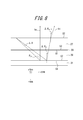
- FIG. 14 is an enlarged view of a portion surrounded by a two-dot chain line in FIG.
- the adhesive layer 115 is usually only about 10 ⁇ m thick and much thinner than the light guide plate 111 with a thickness of several millimeters (mm)
- FIG. 14 shows this in an enlarged manner for explanation.
- FIG. 14 when the image light b11 propagating through the light guide plate 111 passes through the functional film 112 and is incident on the diffraction surface S104 of the diffraction grating 114, zero-order diffracted light b12 is generated in addition to first-order diffracted light.
- the functional film 112 is designed to reflect most of the image light
- the zero-order diffracted light b12 is multi-reflected inside the adhesive layer 115 and is incident on the diffractive surface S104 every time it is incident thereon.
- a part becomes first-order diffracted light b13, passes through the light guide plate 111, and is emitted from the second plane S102.
- a plurality of first-order diffracted lights b13 parallel to each other are generated, and they interfere with each other on the retina of the observer to cause light and dark and unevenness of the image. Note that among the plurality of arrows of the first-order diffracted light b13 in the figure, the light ray at the right end that is first diffracted is the image light that contributes to normal imaging, and the other arrows are unnecessary light.
- an object of the present invention made in view of the above problems is to provide an image display apparatus in which image deterioration due to unnecessary light generated when diffracting image light is reduced.
- the invention of an image display apparatus which achieves the above object is: An image projection optical system which projects image light corresponding to an arbitrary image at infinity; Transmission of the part of the image light projected from the image projection optical system in the first plane and the image light formed in a plate shape having a first plane and a second plane which are parallel and opposite to each other A first light guide section for propagating in the x direction perpendicular to the direction of the optical axis of the image projection optical system while repeating the reflection between the remaining first plane and the second plane; A first spacer plate formed in a plate shape having a third plane and a fourth plane which are parallel and opposed to each other, and the third plane is joined to the first plane; A first output deflection unit formed or joined in the fourth plane, which diffracts a part of the image light transmitted through the first plane in a direction substantially perpendicular to the first plane; It is characterized by having.
- the first output deflection unit includes a reflective diffraction surface.
- a propagation angle of the image light in the first space plate, where the image light is diffracted perpendicularly to the fourth plane by the first output deflection unit, ⁇ c1 , of the first space plate Assuming that the thickness is t 1 , the wavelength of the image light is ⁇ , the refractive index of the first spacer is n s1 , and the refractive index of the first light guide is n w1 . It is preferable to satisfy Alternatively, the first output deflection unit includes a transmissive diffraction surface.
- a propagation angle of the image light in the first space plate, where the image light is diffracted perpendicularly to the fourth plane by the first output deflection unit, ⁇ c1 , of the first space plate Assuming that the thickness is t 1 , the wavelength of the image light is ⁇ , and the refractive index of the first spacer is n s1 . May be satisfied.
- T v1 abs (n (n s1 t 1 ) -m (n w1 T 1 ))
- the above-described image display device is formed in a plate shape having fifth and sixth planes parallel and opposite to each other, and the image of the part diffracted by the first output deflection unit
- a second spacer plate formed in a plate shape having a seventh plane and an eighth plane which are parallel and opposed to each other, and the seventh plane is joined to the fifth plane;
- a second output deflection unit formed or joined in the eighth plane and diffracting part of the image light transmitted from the fifth plane in a direction substantially perpendicular to the fifth plane.
- the second output deflection unit comprises a reflective diffraction surface.
- the propagation angle of the image light in the spacer in which the image light is diffracted perpendicularly to the eighth plane by the second output deflector is ⁇ c2 , and the thickness of the second spacer is t 2, the wavelength of the image light lambda, the second refractive index n s2 of spacers, when the refractive index of the second light guide section and n w2, Shall meet
- the second output deflection unit includes a transmissive diffraction surface.
- the propagation angle of the image light in the second spacer plate where the image light is diffracted perpendicularly to the eighth plane by the second output deflector is ⁇ c2 of the second spacer plate Assuming that the thickness is t 2 , the wavelength of the image light is ⁇ , and the refractive index of the second spacer is n s2 May be satisfied.
- T v2 abs (n (n s2 t 2 ) -m (n w2 T 2 ))
- the image display apparatus configured as described above, it is possible to reduce image deterioration due to unnecessary light generated when diffracting the image light.
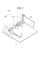
- FIG. 1 is a perspective view of an image display device according to a first embodiment of the present invention. It is a block diagram which shows roughly the structure of the imaging
- FIG. 1 is a perspective view of a display device according to a first embodiment of the present invention.
- the image display device 10 is configured to include an image projection optical system 11 and a pupil expansion optical system 12.
- a direction along the optical axis of the image projection optical system 11 is z direction, and two directions perpendicular to the z direction and perpendicular to each other are x direction (first direction) and y direction (second direction).
- the upper direction is the x direction.
- the lower right direction is the y direction, and the lower left direction is the z direction.
- the image projection optical system 11 projects image light corresponding to an arbitrary image at infinity.
- the pupil expansion optical system 12 receives the image light projected by the image projection optical system 11, expands the exit pupil, and emits the light. By looking at any part of the enlarged projection area PA of the exit pupil, the observer can observe the image.
- the image projection optical system 11 includes a light source 13, an illumination optical system 14, a transmission type chart 15, and a projection optical system 16.
- the light source 13 is driven by a light source driver (not shown), and uses a power supplied from a battery (not shown) to emit a laser as illumination light.
- the wavelength of the laser is, for example, 532 nm.
- the illumination optical system 14 includes a collimator lens 17, a first lenticular lens 18, a second lenticular lens 19, a first lens 20, a diffusion plate 21, and It is configured to include two lenses 22.
- the collimator lens 17, the first lenticular lens 18, the second lenticular lens 19, the first lens 20, the diffusion plate 21, and the second lens 22 are optically coupled.
- the collimator lens 17 converts the illumination light emitted from the light source 13 into parallel light.
- the first lenticular lens 18 has a lens pitch shorter than the width of the luminous flux of the illumination light emitted from the collimating lens 17, for example, 0.1 to 0.5 mm, and has a plurality of lens elements, and the incident parallel luminous flux has a plurality of lenses Configured to be illuminated across elements.
- the first lenticular lens 18 has a refractive power in the x direction, and diverges the illumination light converted into the parallel light beam along the x direction.
- the second lenticular lens 19 has a shorter focal length than the first lenticular lens 18.
- the focal lengths of the first lenticular lens 18 and the second lenticular lens 19 are 1.6 mm and 0.8 mm.
- the second lenticular lens 19 is disposed such that the back focal positions of the first lenticular lens 18 and the second lenticular lens 19 substantially coincide with each other.
- the second lenticular lens 19 has a lens pitch shorter than the width of the luminous flux of the illumination light emitted from the collimating lens 17, for example, 0.1 to 0.5 mm, and has a plurality of lens elements, and a plurality of incident parallel luminous fluxes Configured to be illuminated across the lens elements of The second lenticular lens 19 has a refractive power in the y direction, and diverges the illumination light diverged in the x direction along the y direction.
- a lenticular lens having a divergence angle in the y direction larger than that in the x direction of the first lenticular lens 18 is used as the second lenticular lens 19.
- the first lens 20 is arranged such that the front focal position of the first lens 20 substantially matches the back focal position of the first lenticular lens 18 and the second lenticular lens 19.
- the focal length of the first lens 20 is, for example, 50 mm. Therefore, the first lens 20 converts each of the illumination light components emitted from the plurality of lens elements of the second lenticular lens 19 into parallel light beams with different emission angles, and emits them.
- the diffuser plate 21 is arranged to substantially coincide with the back focal position of the first lens 20. Therefore, the plurality of parallel light beams emitted from the first lens 20 are irradiated in a manner to be folded on the diffusion plate 21. As a result, on the diffusion plate 21, a rectangular illumination light having a Gaussian intensity distribution and a substantially uniform intensity distribution, and having a light beam width longer in the y direction than in the x direction, is emitted.
- the diffusion plate 21 is driven by a diffusion plate drive mechanism (not shown), vibrates along a plane perpendicular to the optical axis OX, and reduces the visibility of speckle.
- the diffusion plate 21 is, for example, a holographic diffuser whose diffusion angle is designed to be rectangular, and irradiates the illumination light emitted from the diffusion plate 21 to the entire region of the rectangular transmission type chart 15 described later with uniform intensity and without excess or deficiency. Do.
- the second lens 22 is arranged such that the front focal position of the second lens 22 substantially coincides with the position of the diffusion plate 21.
- the focal length of the second lens 22 is, for example, 26 mm.
- the second lens 22 condenses illumination light incident at various angles at each angle.
- the transmission chart 15 is disposed at the back focal position of the second lens 22.
- the transmission chart 15 is, for example, a rectangle having a length of 5.6 mm in the x direction and 4.5 mm in the y direction.
- the transmission chart 15 is driven by a chart drive unit (not shown) to form an arbitrary image to be displayed on the image display device 10.
- a chart drive unit not shown
- Each parallel light flux collected at each angle is irradiated to each pixel constituting the image of the transmission type chart 15. Therefore, the light transmitted through each pixel constitutes the image light.
- the projection optical system 16 is arranged such that the exit pupil of the projection optical system 16 and the diffusion plate 21 are optically conjugate. Therefore, the shape of the exit pupil is a rectangle longer in the y direction than in the x direction.
- the projection optical system 16 has a focal length of 28 mm, for example, and projects the image light on which the transmission type chart 15 is projected at infinity.
- the projection optical system 16 is a group of parallel light beams having angular components in the x and y directions according to the height of the object from the optical axis OX in the x and y directions of each pixel of the transmission chart 15. Emit as image light.
- the light is emitted in an angular range of ⁇ 4.6 ° in the x direction and ⁇ 5.7 ° in the y direction.
- the image light projected by the projection optical system 16 is incident on the pupil magnification optical system 12.
- the pupil expansion optical system 12 includes a polarizer 23, a first propagation optical system 24, a half wave plate 25, and a second propagation optical system 26.
- the polarizer 23, the first propagation optical system 24, the half-wave plate 25, and the second propagation optical system 26 are displayed with a large distance for the sake of explanation. Are placed close to each other as shown in FIG.
- the polarizer 23 is disposed between the exit pupil of the projection optical system 16 and the projection optical system 16, receives image light emitted from the projection optical system 16, and emits S-polarized light.
- the first propagation optical system 24 includes an incident area (not shown in FIG. 3) of a second plane (not shown in FIG. 3) of a first light guide (not shown in FIG. 3) to be described later.
- the exit pupils of the projection optical system 16 are arranged so as to be aligned, and the exit pupil projected as S-polarized light by the polarizer 23 is enlarged in the x direction and emitted (see the reference “Ex”).
- the half-wave plate 25 rotates the polarization plane of the image light expanded in the x direction by 90 °.
- the second propagation optical system 26 expands the image light whose polarization plane has been rotated by the half-wave plate 25 in the y direction and emits the light (see reference numeral “Ey”).
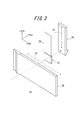
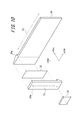
- the first propagation optical system 24 includes a first light guide 27, a first polarization beam split film 28, a first spacer 29, a first input deflection unit 30, and a first light deflector 27. It is configured to include one output deflection unit 31.
- the first polarization beam split film 28 is vapor-deposited on the first light guide 27 as described later, and can not be separated from each other, but in FIG. 4, it is schematically separated and described.
- the first light guide 27 is a transparent flat plate having a first plane S1 and a second plane S2 which are parallel and opposite to each other.
- the first spacing plate 29 is formed in a plate shape having a third plane S3 and a fourth plane S4 which are parallel and opposed to each other, and the third plane S3 is a first plane of the first light guide 27.
- the first polarization beam split film 28 is bonded to S1.
- the first input deflection unit 30 is a prism, and has a flat input side bonding surface S5 and an inclined surface S6 inclined with respect to the input side bonding surface S5.
- the first output deflection unit 31 is a plate-like reflective diffraction grating whose surface on the first space plate 29 side is a diffractive surface S7.
- the third plane S3, the fourth plane S4, and the diffraction plane of the first output deflection unit 31 of the first spacing plate 29 are provided.
- a first polarized beam split film 28 having substantially the same size as S7 is formed by vapor deposition.
- the area of the first plane S1 where the first polarized beam split film 28 is formed is bonded to the third plane S3 of the first spacer 29 by a transparent adhesive.
- the diffractive surface S7 of the first output deflection unit 31 is joined to the fourth plane S4 of the first spacing plate 29.
- the first input deflection unit 30 is bonded to the area on the input side bonding surface S5 with a transparent adhesive in a region other than the region where the first polarization beam split film 28 is formed in the first plane S1.
- the first Propagation optical system 24 is integrated.
- the region where the first input deflection unit 30 is provided is the incident region
- the region where the first output deflection unit 31 is provided is the It is called an exit area (see FIG. 5).
- the first polarization beam splitting film 28 is formed so as to slightly protrude toward the incident area side.
- the integrated first propagation optical system 24 is flat and has a length direction ("x direction" in Fig. 4) and a width direction (Fig. 4) of the first propagation optical system 24 and the first light guide 27.
- the lengths Wx1 and Wy1 of “y direction” in 4 are, for example, 60 mm and 20 mm.
- the length Wx1e in the longitudinal direction of the first polarization beam splitting film 28 is, for example, 50 mm.
- the length Wx1i of the first input deflection unit 30 in the longitudinal direction is, for example, 7 mm.
- the first input deflection unit 30 may include a portion having a surface other than the inclined surface S6 as a surface facing the input side bonding surface S5.
- the longitudinal length Wx1i of the above is a length along the longitudinal direction of the inclined surface S6.
- the first polarization beam splitting film 28 is a multilayer film designed to transmit light incident from a substantially perpendicular direction and to reflect most of the light incident from an oblique direction.
- a thin film having low-pass or band-pass spectral reflection characteristics can have such characteristics.
- the first polarization beam splitting film 28 has a transmittance for obliquely incident light, which varies according to the position along the x direction.
- the first polarization may be such that the transmittance is increased in a geometric progression according to the distance from one end of the first polarization beam splitting film 28 on the first input deflection unit 30 side (see FIG. 6).
- a beam split film 28 is formed.
- the distance from the vapor deposition source is arranged to change according to the planar distance from the first input deflection unit 30, and the difference in the distance It is possible to form a film by designing in advance to have a desired reflection characteristic at each position according to the difference in film thickness).
- quartz transparent medium having a thickness of 3 mm, that is, a length in the z direction is used (see FIG. 4).
- quartz transparent medium
- it has heat resistance against heating when depositing the first polarization beam split film 28, and it is hard so that it is difficult to warp against film stress Have.
- An AR film 32 is formed on the second plane S2 of the first light guide 27.
- the AR film 32 suppresses the reflection of image light incident from the vertical direction.
- the AR film 32 is designed and formed so that the film stress is balanced with the film stress of the first polarization beam split film 28. By balancing the film stress, distortion of the first propagation optical system 24 can be suppressed, which can contribute to good propagation of the image light.
- a plate-like member made of, for example, quartz is used as the first spacer 29.
- the first spacing plate 29 is bonded to the first plane S1 of the first light guide 27 on which the first polarization beam splitting film 28 is formed by a transparent adhesive.
- the first spacer 29 has a refractive index substantially equal to that of the transparent adhesive, and the refractive index is, for example, 1.5. By setting the refractive index substantially equal to that of the transparent adhesive, it is possible to prevent the occurrence of multiple reflections of image light in the transparent adhesive.
- the thickness of the first spacer i.e., the length in the z direction, may be, for example, 1.9 mm.
- the first input deflection unit 30 is formed of, for example, quartz. By forming the first input deflection unit 30 using quartz which is the same material as the first light guide unit 27, the reflection at the interface between the input side joint surface S5 and the first plane S1 is ideal. Can be reduced to
- Aluminum is vapor-deposited on the inclined surface S6 of the first input deflection unit 30, and functions as a reflective film. As shown in FIG. 5, the normal to the inclined surface S6 extends to the emission area side of the first light guide 27. Therefore, a light flux vertically incident on the second plane S2 of the first light guide portion 27 in the incident region is reflected by the inclined surface S6 inside the first input deflection portion 30, and is propagated toward the emission region Ru.
- the apex angle formed by the input side joint surface S5 and the inclined surface S6 will be described later. Further, the interface between the first input deflection unit 30 and the first spacing plate 29 and the first output deflection unit 31 is colored in black, and absorbs the incident light without reflecting it.
- the first output deflection unit 31 is a reflective diffraction grating whose surface in contact with the first spacing plate 29 is a diffractive surface S7.
- the lengths in the length direction (x direction) and the width direction (y direction) of the first output deflection unit 31 are the same as those of the first polarization beam splitting film 28, that is, 50 mm and 20 mm, respectively.
- the thickness, i.e., the length in the z direction can be, for example, 2 mm or 3 mm.
- the diffractive surface S7 is provided with a large number of diffractive grooves extending in the y direction orthogonal to the direction in which the image light propagates.
- the grating density of the diffractive surface S7 is, for example, 2150 [l / mm], and the first-order diffracted light of the image light incident on the diffractive surface S7 according to the wavelength ⁇ of the image light in vacuum is substantially perpendicular to the diffractive surface S7. It is designed to be in the direction. Further, the diffraction grooves of the diffraction surface S7 are shaped and arranged such that the diffraction efficiency of the first-order diffracted light is maximized. It is also possible to form a diffractive surface directly on the fourth surface S4 of the first spacing plate instead of the first output deflection section 31 and use it as the first output deflection section.
- the apex angle formed by the input-side joint surface S5 and the inclined surface S6 of the first input deflection unit 30 is determined based on the critical angle in the second plane S2 of the first light guide 27 as described below.
- the first propagation optical system 24 is disposed so that the light beam Lx parallel to the optical axis OX of the image projection optical system 11 is perpendicularly incident from the outside on the incident area on the second plane S2.
- the light flux Lx vertically incident on the incident region enters the first input deflection unit 30 from the first light guide 27 and is obliquely reflected by the inclined surface S6.
- the obliquely reflected light flux Lx is transmitted through the first light guide 27 into the second plane S2.
- the apex angle formed by the input side joint surface S5 of the first input deflection unit 30 and the inclined surface S6 is determined so that the light beam Lx incident on the second plane S2 in the first light guide 27 is totally reflected.
- the first light guide 27 is formed of quartz, so the critical angle is 43.6 °.
- the incident angle ⁇ to the second plane S 2 in the first light guide 27 with respect to the luminous flux of the object height vertically incident from the image projection optical system 11 is the input side joint surface of the first input deflection unit 30 Because the angle of inclination of the inclined surface S6 with respect to S5 is a double angle, the angle of inclination needs to be 21.8 ° or more. In the present embodiment, the inclination angle is, for example, 25.8 ° and 21.8 ° or more.
- the angle of a ray incident on the incident area of the second plane S2 for example, the angle of the incident ray On the air side, ⁇ 4.6 ° in the x direction, ⁇ 5.7 ° in the y direction, ⁇ 3.1 ° in the x direction, and y direction in the medium of the first light guide 27 formed of quartz It is possible to limit the angle of the image light according to all object heights in the first propagation optical system 24 described above.
- the luminous flux can be totally reflected in the first light guide 27 at the second plane S2.
- the light beam Lx vertically incident on the incident region of the second plane S2 is reflected by the inclined surface S6 of the first input deflection unit 30,
- the light is obliquely incident on the emission area of the second plane S2 inside the first light guide portion 27.
- the light beam Lx incident from an oblique direction is incident on the second plane S2 at an angle exceeding the critical angle, and is totally reflected.
- the totally reflected light beam Lx obliquely enters the first polarization beam splitting film 28, transmits only a predetermined amount of light, and reflects the remaining light.
- the light beam Lx reflected by the first polarization beam splitting film 28 again enters the second plane S2 at an angle exceeding the critical angle, and is totally reflected. Thereafter, the light beam Lx is propagated in the x direction of the first light guide 27 while repeating partial reflection in the first polarization beam split film 28 and total reflection in the second plane S2. However, each time the light is incident on the first polarization beam split film 28, the light is transmitted at a predetermined rate and emitted to the first spacer 29.
- the light beam Lx incident from the third plane S3 of the first space plate 29 is diffracted by the diffractive surface S7 of the first output deflection unit 30 joined to the fourth plane S4, and is perpendicular to the diffractive surface S7. It is deflected in the direction.
- the light beam Lx deflected in the direction perpendicular to the diffractive surface S7 is transmitted through the first spacing plate 29, vertically incident on the first polarization beam splitting film 28, and transmitted at a transmittance of substantially 100%. Further, the light is perpendicularly incident on the second plane S2 and emitted from the second plane S2 to the outside.
- the half-wave plate 25 (see FIG. 3) is formed in a shape substantially the same size as the emission area of the second plane S2.
- the half-wave plate 25 is disposed with an air gap at a position facing the emission region of the second plane S2. Therefore, a light beam obliquely incident on the second plane S2 at an angle larger than the critical angle in the first light guide portion 27 does not pass through the second plane S2, and total reflection is ensured.
- the half-wave plate 25 rotates the polarization plane of the light beam emitted from the first propagation optical system 24 by 90 degrees.
- the second propagation optical system 26 includes a second light guide 33, a second polarization beam split film 34, a second spacer 35, a second input deflection unit 36, and It comprises the output deflection part 37 of two. Similar to the first propagation optical system 24, these constituent members are in the form of an integrated flat plate, and the width direction of the second propagation optical system 26 and the second light guide portion 33 (the "x direction in FIG. The lengths Wx2 and Wy2 of the length direction (the “y direction” in FIG. 7) are, for example, 50 mm and 110 mm.
- the longitudinal length Wy2e of the second polarization beam splitting film 34, the second spacer plate 35 and the second output deflection unit 37 in the second propagation optical system 26 is, for example, 100 mm.
- the length Wy2i of the second input deflection unit 36 in the longitudinal direction is, for example, 10 mm.
- the functions of the second light guide 33, the second polarization beam split film 34, the second spacer 35, the second input deflection unit 36, and the second output deflection unit 37 are respectively the first light guide Similar to the unit 27, the first polarization beam split film 28, the first spacer 29, the first input deflection unit 30, and the first output deflection unit 31.
- the second light guide 33 has a fifth plane S8 on which the second polarization beam split film 34 is deposited and a sixth plane S9 opposed to the fifth plane S8.
- the emission area of the second plane S2 of the first propagation optical system 24 and the incident area of the sixth plane S9 of the second propagation optical system 26 face each other.
- the propagation optical system 26 is disposed in a posture rotated 90 ° around a straight line parallel to the z direction with respect to the first propagation optical system 24 (see FIG. 3). Therefore, the second propagation optical system 26 enlarges the image light emitted from the first propagation optical system 24 in the y direction and emits it.
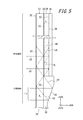
- the configuration of the first propagation optical system 24 including the first space plate 29 it is possible to reduce the image deterioration caused by the zeroth-order diffracted light generated in the diffractive surface S7 of the first output deflection unit 31. explain.
- the first one is most along the x direction.
- the light beam from the output deflection unit 31 is referred to as a first light beam b1
- the light beam from the first input deflection unit 30 is referred to as a second light beam b2.
- the following description describes the second ray b2, but the same applies to the first ray b1 and other rays in the luminous flux Lx.
- the second light ray b2 is incident on the first light guide 27 from the second plane S2, is reflected by the inclined surface S6 of the first input deflection unit 20, and is incident on the first light guide 27. , And propagate in the first light guide 27.
- a first polarization beam split film a part of which is deposited on the first plane S1
- the light passes through the third plane S3 and enters the first spacing plate 29 from the third plane S3
- a part of the second light beam b2 travels in the first spacing plate 29 to the fourth plane S4, and
- the light is incident on the diffractive surface S7 of the first output deflection unit 31 joined to the plane S4 of FIG.
- the incident second light beam b2 is emitted in the direction perpendicular to the diffractive surface S7 as a third light beam b3 which is first-order diffracted light.
- the third light beam b3 passes through the first spacing plate 29 and the first light guide 27 and exits from the second plane S2.
- a portion of the second beam b2 in the diffraction plane S7, and a fourth light beam b4 is a zero-order diffracted light
- First polarization beam splitter film 28 disposed between the first spacers 29 and the first light guide portion 27 reflects a large portion of the image light of a wavelength ⁇ incident at the incident angle theta 1 Characteristics
- the fourth ray b4 of the zeroth-order diffracted light is specularly reflected, propagates again in the second spacer plate 20, and is incident on the fourth plane S4.
- a part of the fourth light beam b4 emitted from the fourth plane S4 is first-order diffracted by the diffractive surface S7 of the first output deflection unit 31 and emitted as the fifth light beam b5 in the direction perpendicular to the diffractive surface S7 .
- the fifth light ray b5 passes through the first spacing plate 29 and the first light guide 27 and exits from the second plane S2. Also, the remaining part of the fourth light beam b4 propagates in the first spacing plate 29 again in the regular reflection direction.
- the occurrence of the zeroth-order diffracted light causes the third light beam b3 and the fifth light beam b5 parallel to each other based on the second light beam b2 to be emitted toward the observer's eye.
- the third light beam b3 and the fifth light beam b5 are focused at the same point on the retina of the observer's eye to cause interference.
- Such interference causes bright and dark stripes to form on the retina in the eye and affects the quality of the observed image.
- the thickness of the first spacer plate is t 1
- the optical path difference due to one reflection in the first spacer plate 29 is 2t 1 / cos ⁇ 1.
- the refractive index of the first spacers 29 n s1 the wavelength of the image light in the first spacers and lambda ', satisfy the following equation.
- a ray b p indicates a ray which is diffracted by the diffractive surface S ⁇ b> 7 of the first output deflection unit 31 and is reflected perpendicularly to the diffractive surface S ⁇ b> 7.
- the propagation angle in the first spacer 29 is assumed to be ⁇ c1 .
- the light beam b i is a light beam whose propagation angle differs from the light beam b p in the first spacing plate 29 in the xz in-plane direction by the pitch ⁇ 1 of light and dark of the interference fringes.
- the light ray b i is converted into a bright and dark pitch ⁇ air1 of interference fringes observed from the outside of the image display device 10 by refraction when exiting from the first light guide 27.
- the refractive index of the first light guide 27 is n w1 and ⁇ d1 and ⁇ air1 are minute, the approximation similar to that described above is performed. It becomes.
- ⁇ air1 decreases as t 1 increases. That is, by providing the first spacers 29 having a thickness t 1, fringe spacing [Delta] [theta] Air1 interference fringes compared with the case without the first spacing plate 29 is reduced. By reducing the stripe interval ⁇ air1 , the visibility of the image is improved. Therefore, the first spacer 29 can reduce image deterioration due to interference fringes caused by the zeroth-order diffracted light.
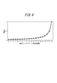
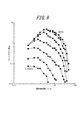
- the spatial contrast sensitivity function corresponds to the transfer function of the visual system, the value of which depends on the spatial frequency and the brightness of the object to be observed.
- Fig. 9 (Asakura Shoten quoted from the structure and initial function of visual system I visual system (P 209).
- the source is Van Nes FL, Bouman MA: Spatial modulation transfer in the human eye. Journal of the Optical Society of America, 57: 401 Experimental results as shown in -406, 1967.) are widely known.
- a plurality of lines on the graph of FIG. 9 correspond to differences in brightness, and the graph on the upper right has values in a bright environment.
- the horizontal axis indicates the repetition period of the structure per degree of angle. According to this, it can be seen that at spatial frequencies of 30 c / d and above, even when a bright object is viewed, the contrast appears to be lower than in the low frequency region. Therefore, setting the period of the interference fringes to 30 c / d or more is one indication of the present invention.
- the period 30c / d of the interference fringes corresponds to a two-point resolution of 0.0006 [rad] of the human eye, and this spatial frequency is equivalent to a frequency that can be resolved by a person with visual acuity of 0.5.
- the contrast of the interference fringes is low, and it is hard to be recognized by the human eye.
- the two-point resolution of 0.0003 [rad] corresponds to 60 c / d as a spatial frequency, which corresponds to a limit of 1.0 for human vision when it is converted to visual acuity. Also from the graph of FIG. 9, it can be seen that the contrast sensitivity is greatly reduced at 60 c / d.
- the interference fringes are not visually recognized if the fringe spacing ⁇ is smaller than this. That is, It is more preferable if
- the thickness t1 of the first spacing plate 29 satisfies the equation (5), more preferably the equation (6), the brightness and darkness of the image caused by the zeroth-order diffracted light is visually recognized by human eyes It disappears.
- the thickness t1 of the first spacer may be 0.14 mm or more. Furthermore, in order to satisfy Formula (6), the thickness t1 of the first spacer may be 0.28 mm or more.
- the portion of the second light beam b2 transmitted through the first surface S1 becomes zeroth-order diffracted light in the fourth plane S4, and the third light beam in the first spacer 29 is produced.
- a fourth ray b4 reciprocated between the plane S3 and the fourth plane one or more times, and a portion reflected by the first plane S1 of the second ray b2 are the first plane S1 and the second plane S1.
- Interference with the plane S2 may occur between the fourth ray b4 and the sixth ray b6 when coming close to the sixth ray b6 transmitting the first plane S1 by reciprocating back and forth one or more times. .
- T v1 abs (n (n s1 t 1 ) -m (n w1 T 1 ))
- abs (X) is a function that represents the absolute value of X.
- the second propagation optical system 26 by providing the second spacing plate 35, it is possible to suppress the generation of interference fringes due to the influence of zero-order diffracted light of the image light. If there is no first spacer 29 or its thickness is narrow, interference fringes generated in the first propagation optics 24 appear as light and dark in the x direction. On the other hand, in the second propagation optical system 26, since the image light propagates in the y direction, light and dark in the y direction may occur for the same reason as the first propagation optical system 24. By providing the second spacer 35, the distance between the interference fringes becomes narrow, so that the interference fringes become difficult to be recognized visually. Thus, the image quality can be improved.
- T v2 abs (n (n s2 t 2 ) -m (n w2 T 2 ))
- a fifth spacing plate 29 provided with a first spacer 29 between the first output deflecting portion 31a and the second polarization beam splitting film 34 of the second propagation optical system 26. Since the second spacing plate 35 is provided between S8 and the diffractive surface S14 of the second output deflection unit 37, even if interference fringes are generated due to the generation of zero-order diffracted light, the light-dark spacing is By narrowing it so as not to be visible to the human eye, degradation of the observed image is reduced. In particular, with the settings that satisfy Equations (6) and (9), image deterioration can be completely prevented since light and dark are not visually recognized at all in the two-point resolution of a normal human eye.
- the first propagation optical system 24 and the second propagation optical system 26 have a first output deflection unit 31 and a second output deflection having reflection type diffractive surfaces S7 and S14, respectively. Part 37 was used.
- the first propagation optical system 24 and the second propagation optical system 26 instead of the first propagation optical system 24 and the second propagation optical system 26, the first propagation optical system 24a and the second propagation optical system 26a having the transmission type diffractive surface are arranged as shown in FIG. It is also possible to configure the pupil magnification optical system 12.
- the polarizer 23 and the half wave plate 25 have the same functions as those of the first embodiment.
- the first propagation optical system 24a and the second propagation optical system 26a are different from the first embodiment in that image light is emitted from the surface opposite to the incident side.
- FIG. 11 is a view for explaining the diffraction of image light in the first propagation optical system 24a, and shows a first light guiding portion 27 for transmitting the image light, a first polarization beam splitting film 28, and a first spacing plate. 29 and a part of the first output deflection unit 31a are shown in an enlarged manner.
- the first output deflection unit 31a differs from the first output deflection unit 31 of the first embodiment in that the diffractive surface S7 is a transmissive diffraction grating.
- the first output deflection unit 31a is a plate-like member made of a material that transmits light at the wavelength of image light, and the surface facing the diffractive surface S7 is a flat light transmission surface. .
- the other configuration is the same as that of the first propagation optical system 24 of the first embodiment.
- the image light transmitted through the first beam splitting film 28 is transmitted through the first spacing plate 29 and is diffracted by the diffractive surface S7 of the first output deflecting unit 31 to be approximately the same as the diffractive surface S7. Ejected in the orthogonal direction.
- the second propagation optical system 26a is similarly configured.
- the observer can observe the image from the + z direction side (upper right side in FIG. 10) of the second propagation optical system 26a.
- the same effect as that of the first embodiment is obtained.
- light b p receives the diffracted by the diffraction surface S7 in the first output deflecting unit 31a, shows a light ray which passes perpendicularly to the diffraction plane S7.
- the ray b i is a ray different from the ray b p in propagation angle in the xz plane direction by the pitch ⁇ of interference fringes.
- Equation (2) the pitch ⁇ 1 of the light and dark of the interference fringes can be expressed by Equation (2).
- an angle at which the light ray b p is diffracted by the diffractive surface S7 of the first output deflection unit 31 and transmitted in the direction perpendicular to the diffractive surface S7 is ⁇ c1
- the light ray b i makes the first output deflection portion 31 a
- the propagation angle ⁇ air1 that permeates and is emitted into the air can be expressed by the following equation. However, the same approximation as in the first embodiment is performed.
- equation (5) is changed to If so, the contrast of the interference fringes can be low and it can be difficult to view.
- the interference fringes are almost invisible to human eyes.
- the contrast of the interference fringes can be lowered and it can be made difficult to see.
- the interference fringes are not visually recognized by satisfying the following equation.
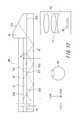
- FIG. 12 is a side view schematically showing an optical system of the image display device according to the second embodiment.
- the image display apparatus according to the second embodiment has a propagation optical system in only the x direction, unlike the first embodiment.
- the propagation optical system 44 guides the image light from the image projection optical system 41 mounted on the head and arranged on the side of the head in front of the user's eyes while the propagation optical system 44 Project the image towards the
- the image projection optical system 41 includes a display element 42 such as an LCD or an organic EL display, and a projection optical system 43 for projecting image light from the display element.
- the projection optical system 43 is disposed such that the exit pupil is aligned with the incident surface of the propagation optical system 44 (the second plane S22 of the light guide 45).
- the propagation optical system 44 further includes a light guide 45, a polarization beam split film 46, a spacer 47, an input deflection unit 48, and an output deflection unit 49.
- Each component of the propagation optical system 44 is the first light guiding portion of the first propagation optical system 24 shown in FIG. 4 and FIG. 5 of the first embodiment except for differences in size and fine shape.
- the first polarization beam split film 28, the first spacing plate 29, the first input deflection unit 30, and the first output deflection unit 31 are configured in the same manner.
- the first plane S21, the second plane S22, the third plane S23, the fourth plane S24, the input-side joint surface S25, the inclined surface S26, and the diffractive surface S27 are also the first embodiment of the first embodiment.
- Each of these components propagates the image light incident from the image projection optical system 41 in the same manner as the first propagation optical system 24 of the first embodiment, so in the present embodiment the configuration and operation of each component I omit explanation.
- the spacer 47 is provided between the light guide 45 and the output deflector 49 as in the first embodiment, the interference due to the zero-order diffracted light is the same as in the first embodiment. Since it becomes difficult to visually recognize light and dark, it is possible to reduce the deterioration of the observed image. Further, by satisfying the equation (4), the light and dark due to the interference fringes will not be visible to the human eye. Furthermore, it is also the same as in the first embodiment that it is preferable to satisfy the relationship of the formula (5).
- the dimensions, shapes, arrangements, and the like of the components described in the first embodiment are merely examples, and various dimensions, shapes, arrangements, and the like can be taken within the scope of the present invention.
- the image projection optical system 11 may have various configurations as long as the exit pupil for projecting the display image coincides with the incident area of the pupil expansion optical system 12.
- the first output deflection unit 31 is not a reflective diffraction grating but a transmissive diffraction grating, and projected image light is emitted from the surface facing the diffractive surface S7 of the first output deflection unit 31. You may do so.
- a diffractive surface is directly formed on the fourth surface S4 of the first spacing plate 29, and this is used as the first output deflection. It is also possible to use a department. The same applies to the second propagation optical system 26 and the second embodiment.
Abstract
L'invention concerne un dispositif d'affichage d'image comprenant : un système optique de projection d'image qui projette une lumière d'image à une distance infinie ; une première unité de guidage de lumière (27) formée dans une forme de plaque ayant une première surface plate (S1) et une deuxième surface plate (S2) et propageant la lumière d'image dans une direction x, tout en répétant la transmission dans la première surface plate (S1) d'une partie de la lumière d'image projetée par le système optique de projection d'image, et la réflexion entre la première surface plate (S1) et la deuxième surface plate (S2) de la lumière d'image restante ; une première plaque d'espacement (29) formée dans une forme de plaque ayant une troisième surface plate (S3) et une quatrième surface plate (S4) de telle sorte que la troisième surface plate (S3) est reliée à la première surface plate (S1) ; et une première unité de déviation de sortie (31) formée sur la quatrième surface plate (S4) ou reliée à cette dernière de telle sorte que la partie de la lumière d'image transmise à travers la première surface plate (S1) est diffractée dans une direction sensiblement orthogonale à la première surface plate (S1).
Priority Applications (1)
| Application Number | Priority Date | Filing Date | Title |
|---|---|---|---|
| US15/257,155 US10108009B2 (en) | 2014-03-20 | 2016-09-06 | Image display device |
Applications Claiming Priority (2)
| Application Number | Priority Date | Filing Date | Title |
|---|---|---|---|
| JP2014059021A JP6265805B2 (ja) | 2014-03-20 | 2014-03-20 | 画像表示装置 |
| JP2014-059021 | 2014-03-20 |
Related Child Applications (1)
| Application Number | Title | Priority Date | Filing Date |
|---|---|---|---|
| US15/257,155 Continuation US10108009B2 (en) | 2014-03-20 | 2016-09-06 | Image display device |
Publications (1)
| Publication Number | Publication Date |
|---|---|
| WO2015141168A1 true WO2015141168A1 (fr) | 2015-09-24 |
Family
ID=54144155
Family Applications (1)
| Application Number | Title | Priority Date | Filing Date |
|---|---|---|---|
| PCT/JP2015/001201 WO2015141168A1 (fr) | 2014-03-20 | 2015-03-05 | Dispositif d'affichage d'image |
Country Status (3)
| Country | Link |
|---|---|
| US (1) | US10108009B2 (fr) |
| JP (1) | JP6265805B2 (fr) |
| WO (1) | WO2015141168A1 (fr) |
Families Citing this family (8)
| Publication number | Priority date | Publication date | Assignee | Title |
|---|---|---|---|---|
| JP6477051B2 (ja) | 2015-03-09 | 2019-03-06 | セイコーエプソン株式会社 | 画像表示装置 |
| JP6597197B2 (ja) * | 2015-11-05 | 2019-10-30 | セイコーエプソン株式会社 | 光束径拡大素子および表示装置 |
| GB2550958B (en) | 2016-06-03 | 2022-02-23 | Bae Systems Plc | Waveguide structure |
| EP3660551B1 (fr) * | 2017-10-24 | 2022-11-30 | LG Chem, Ltd. | Plaque de guidage de lumière diffractée et procédé de fabrication d'une plaque de guidage de lumière diffractée |
| FI129167B (en) | 2017-12-22 | 2021-08-31 | Dispelix Oy | Interference-free waveguide display |
| CN110082907B (zh) * | 2018-01-26 | 2021-02-23 | 华为技术有限公司 | 一种光波导结构及显示装置 |
| JP6984752B2 (ja) * | 2018-07-10 | 2021-12-22 | 株式会社島津製作所 | 画像表示装置 |
| CN109683317A (zh) * | 2018-12-28 | 2019-04-26 | 北京灵犀微光科技有限公司 | 增强现实目镜装置和增强现实显示装置 |
Citations (5)
| Publication number | Priority date | Publication date | Assignee | Title |
|---|---|---|---|---|
| WO2006025317A1 (fr) * | 2004-08-31 | 2006-03-09 | Nikon Corporation | Système optique de dilatation de flux lumineux et unité d'affichage d'image |
| JP2008535032A (ja) * | 2005-04-04 | 2008-08-28 | ミラージュ イノヴェイションズ リミテッド | 多平面光学装置 |
| JP2010282231A (ja) * | 2004-03-29 | 2010-12-16 | Sony Corp | 画像表示装置 |
| US20120127577A1 (en) * | 2009-07-31 | 2012-05-24 | Horiba Jobin Yvon Sas | Planar optical system for wide field-of-view polychromatic imaging |
| JP2013061480A (ja) * | 2011-09-13 | 2013-04-04 | Olympus Corp | 光学素子及び光学機構 |
Family Cites Families (2)
| Publication number | Priority date | Publication date | Assignee | Title |
|---|---|---|---|---|
| EP1748305A4 (fr) * | 2004-05-17 | 2009-01-14 | Nikon Corp | Élément optique, système optique combinateur et unite d'affichage d'image |
| GB201212270D0 (en) * | 2012-07-10 | 2012-08-22 | Light Blue Optics Ltd | Head up displays |
-
2014
- 2014-03-20 JP JP2014059021A patent/JP6265805B2/ja not_active Expired - Fee Related
-
2015
- 2015-03-05 WO PCT/JP2015/001201 patent/WO2015141168A1/fr active Application Filing
-
2016
- 2016-09-06 US US15/257,155 patent/US10108009B2/en active Active
Patent Citations (5)
| Publication number | Priority date | Publication date | Assignee | Title |
|---|---|---|---|---|
| JP2010282231A (ja) * | 2004-03-29 | 2010-12-16 | Sony Corp | 画像表示装置 |
| WO2006025317A1 (fr) * | 2004-08-31 | 2006-03-09 | Nikon Corporation | Système optique de dilatation de flux lumineux et unité d'affichage d'image |
| JP2008535032A (ja) * | 2005-04-04 | 2008-08-28 | ミラージュ イノヴェイションズ リミテッド | 多平面光学装置 |
| US20120127577A1 (en) * | 2009-07-31 | 2012-05-24 | Horiba Jobin Yvon Sas | Planar optical system for wide field-of-view polychromatic imaging |
| JP2013061480A (ja) * | 2011-09-13 | 2013-04-04 | Olympus Corp | 光学素子及び光学機構 |
Also Published As
| Publication number | Publication date |
|---|---|
| JP2015184385A (ja) | 2015-10-22 |
| US20160370582A1 (en) | 2016-12-22 |
| JP6265805B2 (ja) | 2018-01-24 |
| US10108009B2 (en) | 2018-10-23 |
Similar Documents
| Publication | Publication Date | Title |
|---|---|---|
| WO2015141168A1 (fr) | Dispositif d'affichage d'image | |
| EP3583351B1 (fr) | Structure de guide d'onde | |
| US10409069B2 (en) | Display device and light guide device | |
| CN105929535B (zh) | 图像显示装置 | |
| JP7232182B2 (ja) | 高分解能のデジタル化された表示のための方法及びシステム | |
| TWI653478B (zh) | 使用矩形波導的孔徑倍增器 | |
| JP6867999B2 (ja) | 反射型転換アレイを有する結像光ガイド | |
| JP6992251B2 (ja) | 映像表示装置、および導光装置 | |
| US20160370693A1 (en) | Image display device | |
| US9885877B2 (en) | Image display apparatus having an optical scanner | |
| US20200183079A1 (en) | Display device comprising a light guide | |
| CN107076986B (zh) | 成像光学器件和数据眼镜 | |
| CN107861243B (zh) | 光学元件和显示装置 | |
| EP3236305A1 (fr) | Élément optique, dispositif d'affichage et procédé de fabrication d'un élément optique | |
| US10012833B2 (en) | Displaying apparatus including optical image projection system and two plate-shaped optical propagation systems | |
| WO2019187332A1 (fr) | Plaque de guidage de lumière, procédé de fabrication de plaque de guidage de lumière, et dispositif d'affichage vidéo | |
| EP3361147A1 (fr) | Structure de guide d'onde | |
| JP2017161564A (ja) | 導光装置及び虚像表示装置 | |
| JP6296841B2 (ja) | 表示装置 | |
| US20220413283A1 (en) | Waveguide structure | |
| JP2017161563A (ja) | 導光装置及び虚像表示装置 | |
| GB2561944A (en) | Waveguide structure |
Legal Events
| Date | Code | Title | Description |
|---|---|---|---|
| 121 | Ep: the epo has been informed by wipo that ep was designated in this application |
Ref document number: 15764420 Country of ref document: EP Kind code of ref document: A1 |
|
| NENP | Non-entry into the national phase |
Ref country code: DE |
|
| 122 | Ep: pct application non-entry in european phase |
Ref document number: 15764420 Country of ref document: EP Kind code of ref document: A1 |