WO2015140609A1 - Method for the remote detection of leakages in hydraulic circuits, and apparatus thereof - Google Patents
Method for the remote detection of leakages in hydraulic circuits, and apparatus thereof Download PDFInfo
- Publication number
- WO2015140609A1 WO2015140609A1 PCT/IB2014/066386 IB2014066386W WO2015140609A1 WO 2015140609 A1 WO2015140609 A1 WO 2015140609A1 IB 2014066386 W IB2014066386 W IB 2014066386W WO 2015140609 A1 WO2015140609 A1 WO 2015140609A1
- Authority
- WO
- WIPO (PCT)
- Prior art keywords
- leakages
- hydraulic circuit
- pressure
- leakage
- remote detection
- Prior art date
Links
Classifications
-
- G—PHYSICS
- G01—MEASURING; TESTING
- G01M—TESTING STATIC OR DYNAMIC BALANCE OF MACHINES OR STRUCTURES; TESTING OF STRUCTURES OR APPARATUS, NOT OTHERWISE PROVIDED FOR
- G01M3/00—Investigating fluid-tightness of structures
- G01M3/02—Investigating fluid-tightness of structures by using fluid or vacuum
- G01M3/26—Investigating fluid-tightness of structures by using fluid or vacuum by measuring rate of loss or gain of fluid, e.g. by pressure-responsive devices, by flow detectors
- G01M3/28—Investigating fluid-tightness of structures by using fluid or vacuum by measuring rate of loss or gain of fluid, e.g. by pressure-responsive devices, by flow detectors for pipes, cables or tubes; for pipe joints or seals; for valves ; for welds
- G01M3/2807—Investigating fluid-tightness of structures by using fluid or vacuum by measuring rate of loss or gain of fluid, e.g. by pressure-responsive devices, by flow detectors for pipes, cables or tubes; for pipe joints or seals; for valves ; for welds for pipes
- G01M3/2815—Investigating fluid-tightness of structures by using fluid or vacuum by measuring rate of loss or gain of fluid, e.g. by pressure-responsive devices, by flow detectors for pipes, cables or tubes; for pipe joints or seals; for valves ; for welds for pipes using pressure measurements
Definitions
- the present invention relates to a method, and to the relevant apparatus, for the remote detection of leakages in hydraulic circuits.
- the present invention relates to a method, and to the relevant apparatus, for the remote detection of leakages in hydraulic circuits of automation lines.
- the present invention relates to a method, and to the relevant apparatus, for the remote detection of leakages in hydraulic circuits, specifically of automation lines, that use pressurized fluids.
- the present invention relates to a method, and to the relevant apparatus, for the remote detection of leakages in hydraulic circuits, specifically of automation lines, in cases where such leakages consist in very small quantities.
- the present invention relates to a method, and to the relevant apparatus, to automatically replenish the detected leakages.
- the present invention is preferably, but not exclusively, aimed at identifying both the internal leakages and the external leakages of the users that are part of the aforesaid hydraulic circuits.
- leakages may be due to internal leakages, caused by the degradation of the sealing elements of the various actuators and components, and to external leakages, caused by the loosening of the closures on the circuits of these actuators and components, and/or micro- porosity thereof, and, more generally, to failures or breakages in the hydraulic circuits.
- the oil supply system to these users could be very oversized compared to the real operating needs, in order to compensate losses due to leakages and to ensure continuity of operation of the automation lines or, more generally, of the plant. In extreme cases, if failing to adequately compensate the oil leakages, the plant stop could occur, this resulting in significant economic damages.
- a method for detecting leakages in oil pipelines is known, which is described in the European Patent No. EP 1 007 931 Bl, such method exploiting the corresponding acoustic losses; the teaching of this document, applied in oil pipelines, i.e. in pipelines of indefinite length, can not however be applied in hydraulic circuits, specifically of automation lines, because the leakages therein produced do not have a significant, and therefore detectable, acoustic component.
- the present invention intends mainly to solve and eliminate the problems of the disposal of large amounts of oil and of the consequent manual replenishing in the plant, with a considerable reduction of the management costs.
- the present invention intends in general to solve and eliminate the problem of oil leakages in the hydraulic circuits.
- the present invention intends in particular to solve and eliminate the problem of both internal and external leakages of the users inserted in hydraulic circuits, specifically of automation lines.
- the present invention intends then to solve and eliminate the problems of localization and quantification of the detected hydraulic leakages.
- the present invention intends to solve and eliminate the problem of having to perform manuals maintenance interventions aimed at replenishing amounts of oil to compensate the detected leakages.
- the present invention intends, therefore, to provide:
- the main object of the invention to provide a method, and the relevant apparatus, that, providing to intercept a portion of a hydraulic circuit, specifically of an automation line, to be subjected to the remote detection operations of leakages through two pressure plugs, to connect said portion of hydraulic circuit to the apparatus suitable for the remote detection of said leakages, to start said apparatus, to remove possible air present in said portion of hydraulic circuit by feeding into it an hydraulic fluid, to increase the pressure in said portion of hydraulic circuit up to the operating reference value typical of said hydraulic circuit, specifically of an automation line, subjected to check, to monitor that the pressure level has been stabilized at said typical operating reference value for a predetermined period of time, to measure the pressure values at said two pressure plugs, to determine the pressure gradient and to generate an alarm signal in the event that said pressure gradient exceeds a
- the present invention provides a method, and the relevant apparatus, that provides the possibility to detect leakages due to both internal and external leakages to the users that are part of a hydraulic circuit.
- a not last object of the present invention is to provide a method, and the relevant apparatus, that are cheap, easy to be realized, precisely operable, highly reliable and accurate.
- the present invention provides a method, and the relevant apparatus, having the features of the appended claims 1 and 11, respectively, to which reference is made for sake of brevity.
- a first object of the present invention in case independent and autonomously usable with respect to the other aspects of the invention, a method, and the relevant apparatus for the remote detection of leakages in a hydraulic circuit by determining a pressure gradient at the interception points of a portion of said hydraulic circuit.
- the method and the relevant apparatus according to the present invention have important advantages; in particular, the method and the relevant apparatus according to the present invention allow to achieve a considerable reduction of the management costs together with a significantly lower environmental pollution.
- FIG. 1 is a flow diagram showing the method for the remote detection of leakages in a hydraulic circuit according to the present invention
- FIG. 2 is a schematic representation of the system comprising the apparatus for the remote detection of leakages in a hydraulic circuit according to the present invention in combination with an intercepted portion of said circuit to be subjected to the detection operations;
- FIG. 3 is a schematic representation of the system comprising the apparatus for the remote detection of leakages in a hydraulic circuit according to the present invention in combination with a portion of said circuit comprising an actuator to be subjected to the detection operations, specifically of internal leakages;
- FIG. 4 is a schematic representation of the system comprising the apparatus for the remote detection of leakages in a hydraulic circuit according to the present invention in combination with a portion of said circuit comprising an actuator to be subjected to the detection operations, specifically of external leakages;
- FIG. 5 is a schematic representation of a variant of the system of Fig. 2 further comprising the system for automatically replenishing the detected leakages;
- FIG. 6 is a schematic representation of the apparatus for the remote detection of leakages in a hydraulic circuit according to the present invention in which the fundamental components of the apparatus itself are visible;
- Fig. 7 is a schematic representation of a variant of the apparatus of Fig. 6 further comprising the system for automatically replenishing the detected leakages.
- the method and the relevant apparatus according to the present invention are aimed at reducing the management costs of the plants and the environmental pollution; the achieved result is the almost total recognition of the leakages in the hydraulic circuits subjected to detection, in order to ensure a reduction thereof of 90% or higher.
- the detection is performed in detail on all the plant users, checking in particular both the internal leakages and the external leakages.
- the method and the relevant apparatus according to the present invention allow to precisely identify the leakages sources on the plants, in order to allow prompt maintenance interventions (at least where the leakages of greater amount occur) and to verify afterwards the actual elimination thereof.
- the method and the relevant apparatus according to the present invention also allow to perform the automatic replenishing of the detected leakages.
- the method and the relevant apparatus according to the present invention provide to carry out the detection operations of possible leakages in static conditions, i.e. when the plant is off operation.
- the method and the relevant apparatus according to the present invention use a hydraulic fluid, precisely a hydraulic oil, with properties similar to those of the fluid used in the circuit to be detected, in order to avoid any kind of fouling of the circuit; moreover, the used operating pressure will be the same set on the circuit and/or on the users, in order to avoid any possible damage of the circuit and of the components.
- the apparatus according to the present invention can be conveniently connected to an electronic terminal suitable to realize the graphic representation of the result of the detection operations as well as the comparison with the situation before said detection operations.
- Figure 1 the method according to the present invention for the remote detection of leakages L in a hydraulic circuit C (specifically, in a hydraulic circuit of an automation line) is shown, whose steps listed hereinafter can be fully understood with the help of Figure 2, which schematically shows the system comprising the apparatus 20 for the remote detection of said leakages L in said hydraulic circuit C in combination with a portion 10 of said circuit: intercepting a portion 10 of said hydraulic circuit C, to be subjected to the detection operations, by means of a first 1 and a second 2 pressure plug (step 201),
- step 202 connecting said portion of hydraulic circuit 10, specifically said first 1 and said second 2 pressure plug, to corresponding first 5 and second 6 end of an apparatus 20 suitable for the remote detection of said leakages L, by means of corresponding first 3 and second 4 duct (step 202),
- AV is the volume gradient due to a leakage L in a hydraulic circuit C
- ⁇ is the compressibility coefficient of the hydraulic fluid F present in the hydraulic circuit
- V is the volume of the portion of the hydraulic circuit 10 to be subjected to the detection operations
- ⁇ (PI - P2) is the pressure gradient measured upstream and downstream the portion of hydraulic circuit 10 to be subjected to the detection operations.
- the value of the pressure variation due to a loss or leakage is comparable to the decompression value; in other words, the energy itself undergoing compression in the portion of the circuit, according to the "Pascal principle", generates the thrust and the resulting leakage in the critical areas.
- V ⁇ * (d/2) 2 * 1 (II)
- the temperature parameter is constant (if the measurement is made in a short time, namely 0 to 5 minutes, the temperature parameter can be disregarded since it does not affect the result) and with an operating pressure between 20 and 60 bar (i.e., from 2 to 6 MPa ).
- the method for the remote detection of said leakage L may further comprise the step of:
- the automatic replenishing of the leakage L can occur thanks to having determined the flow rate thereof through the equation III:
- AV volume gradient corresponding to the leakage L and At is the duration of the detection operations.
- the method for the remote detection of said leakages L according to the present invention may further comprise the steps of:
- the predetermined period of time for the stabilization of the pressure level is equal to 2 minutes.
- the predetermined value of pressure gradient ⁇ , ⁇ ', ⁇ " is equal to 0.5 bar, i.e. is equal to 50 kPa according to the international system of units.
- the flow rate of said leakage L is lower than 0.05 ml.
- the method for the remote detection of leakages L provides that the detection operations are carried out in static conditions, i.e. when the automation line is stopped and, more in general, when the hydraulic circuit C is under non-operative conditions.
- the apparatus 20 suitable for the remote detection of leakages L in a hydraulic circuit C, precisely in a hydraulic circuit of an automation line comprises:
- first 5 and a second 6 end suitable to be connected, by means of corresponding first 3 and second 4 duct, to a first 1 and a second 2 pressure plug that intercept a portion 10 of said hydraulic circuit C, to be subjected to the detection operations,
- a compression system 24 for removing possible air A present in said portion of hydraulic circuit 10 and for increasing the pressure of said hydraulic fluid F in said portion of hydraulic circuit 10 up to the operating reference value typical of said hydraulic circuit C to be checked,
- control unit 23 for monitoring, for a predetermined period of time, that the pressure level is stabilized at said typical operating reference value
- an alarm device 27 suitable to be activated in the event that said pressure gradient ⁇ is higher than a predetermined value, preferably is higher than zero, this denoting the presence of a leakage L.
- said casing 21 is made of steel.
- said first 5 and second 6 end comprise tightly sealed couplings with threaded caps or microflexible pipes with threaded end fittings.
- said tank 30 is made of aluminum.
- said hydraulic fluid F is a hydraulic oil of the type HTF 32 having the properties defined according to the ISO 6743-4 and DIN 51524 part HH 1°HL standard rules.
- said feeding system 22 comprises hydraulic/oleodynamic distribution valves, for example AWE sealed valves.
- said compression system 24 comprises pumps and distribution valves.
- said operating reference value typical of said hydraulic circuit C to be checked ranges between 58 and 60 bar, i.e. between 5.8 and 6 MPa according to the international system of units.
- said control unit 23 is a PLC.
- said system for measuring pressure 25 comprises at least a precision pressure gauge, for example of the KELLER type, to detect minimal variations of pressure, of the order of 0.01 bar (1 kPa), in the portion 10.
- a precision pressure gauge for example of the KELLER type, to detect minimal variations of pressure, of the order of 0.01 bar (1 kPa), in the portion 10.
- said alarm device 27 comprises at least one among an acoustic signal (for example, a siren) or a visual signal (for example, a flashing light) or a digital and analogical pressure transducer for signaling the pressure drops through graphs.
- an acoustic signal for example, a siren
- a visual signal for example, a flashing light
- a digital and analogical pressure transducer for signaling the pressure drops through graphs.
- Said apparatus 20 may further comprise:
- said system for measuring pressure 25' comprises at least a precision pressure gauge, for example of the KELLER type, to detect minimal variations of pressure, of the order of 0.01 bar (1 kPa), in the sections 3 and 41.
- a precision pressure gauge for example of the KELLER type, to detect minimal variations of pressure, of the order of 0.01 bar (1 kPa), in the sections 3 and 41.
- Said apparatus 20 may further comprise:
- said system for measuring pressure 25" comprises at least a precision pressure gauge, for example of the KELLER type, to detect minimal variations of pressure, of the order of 0.01 bar (1 kPa), in sections 4 and 42.
- a precision pressure gauge for example of the KELLER type, to detect minimal variations of pressure, of the order of 0.01 bar (1 kPa), in sections 4 and 42.
- Said apparatus 20 may further comprise: - a system for determining flow rate 26 for determining the value of the flow rate of said leakage L detected in said portion of hydraulic circuit 10.
- said system for determining flow rate 26 comprises at least one digital flow switch.
- Said apparatus 20 may further comprise:
- said system 28 for draining said hydraulic fluid F comprises at least one valve for the automatic discharge in tank.
- the apparatus 20 suitable for the remote detection of leakages L in a hydraulic circuit C, precisely in a hydraulic circuit of an automation line, further comprises a drive system 39 for the system of automatic replenishing 29 of the detected leakages L.
- Said system of automatic replenishing 29 receives, through said drive system 39, the value of the flow rate of said leakage L detected in said portion of hydraulic circuit 10 and transmits it to an injector, included in said system of automatic replenishing 29, that, so activated, automatically provides to replenish said portion of hydraulic circuit 10 with a quantity of hydraulic fluid F equal to the value of the flow rate of said leakage L, or anyhow sufficient to compensate said leakage L.
- said injector is of the type supplying a variable flow rate and it allows to automatically replenish values of the variable flow rate L lower than 0.05 ml.
- said injector guarantees an instantaneous, precise and repeatable compensation of the leakages L.
- the embodiment of the present invention as hereinabove described has the further advantage to annul all the possible errors of determination, such as those due to a different operating temperature of the hydraulic fluid compared to the reference one.
- some check tests of the method for the remote detection of leakages in hydraulic circuits, and of the relevant apparatus, subject-matter of the present invention have been carried out, check tests that are reported hereinafter.
- the operating conditions under which the check tests have been carried out have been: Types of pipes taken into account (internal diameter - thickness - length; measurement unit: cm):
- the detection is performed in very short times, lower than 5 minutes, whereby the temperature parameter can be neglected since it does not affect the result.
Landscapes
- Physics & Mathematics (AREA)
- General Physics & Mathematics (AREA)
- Examining Or Testing Airtightness (AREA)
Abstract
The present invention relates to a method, and to the relevant apparatus (20), for the remote detection of leakages (L) in a hydraulic circuit, specifically of an automation line, (C) that uses a pressurized hydraulic fluid (F), said method providing to intercept a portion (10) of said hydraulic circuit (C) to be subjected to the detection operations by means of a first (1) and a second (2) pressure plug, to connect said portion of hydraulic circuit (10) to an apparatus (20) suitable for the remote detection of said leakages (L), to start said apparatus (20), to remove possible air (A) present in said portion of hydraulic circuit (10) by feeding into it said hydraulic fluid (F), to increase the pressure in said portion of hydraulic circuit (10) up to the operating reference value typical of said hydraulic circuit (C) to be checked, to monitor that the pressure level is stabilized at said typical operating reference value for a predetermined period of time, to measure the pressure values (PI, P2) in correspondence of said first (1) and said second (2) pressure plug and to determine the pressure gradient (ΔΡ), and to generate an alarm signal in the event that said pressure gradient (ΔΡ) is higher than a predetermined value, preferably is higher than zero, this denoting the presence of a leakage (L); the method, and the relevant apparatus, according to the present invention may also provide to automatically replenish the detected leakages (L). The present invention is preferably, but not exclusively, aimed at identifying both the internal leakages and the external leakages of the users (40) that are part of the aforesaid hydraulic circuits (C), even if such leakages consist in very small quantities.
Description
Method for the remote detection of leakages in hydraulic circuits, and apparatus thereof
DESCRIPTION
Technical Field
The present invention relates to a method, and to the relevant apparatus, for the remote detection of leakages in hydraulic circuits.
Precisely, the present invention relates to a method, and to the relevant apparatus, for the remote detection of leakages in hydraulic circuits of automation lines.
More precisely, the present invention relates to a method, and to the relevant apparatus, for the remote detection of leakages in hydraulic circuits, specifically of automation lines, that use pressurized fluids.
Even more precisely, the present invention relates to a method, and to the relevant apparatus, for the remote detection of leakages in hydraulic circuits, specifically of automation lines, in cases where such leakages consist in very small quantities.
Moreover, the present invention relates to a method, and to the relevant apparatus, to automatically replenish the detected leakages.
The present invention is preferably, but not exclusively, aimed at identifying both the internal leakages and the external leakages of the users that are part of the aforesaid hydraulic circuits.
Known Prior Art
When managing automated industrial plants that use pressurized fluids, particularly in the automotive, hot moulding, steel making, shipbuilding, earth-moving, military and aerospace sectors, leakages of hydraulic fluids, specifically oil, usually occur.
These leakages may be due to internal leakages, caused by the degradation of the sealing elements of the various actuators and components, and to external leakages, caused by the loosening of the closures on the circuits of these actuators and components, and/or micro- porosity thereof, and, more generally, to failures or breakages in the hydraulic circuits. In some cases, for example where several users are present, the oil supply system to these users could be very oversized compared to the real operating needs, in order to compensate losses due to leakages and to ensure continuity of operation of the automation lines or, more generally, of the plant.
In extreme cases, if failing to adequately compensate the oil leakages, the plant stop could occur, this resulting in significant economic damages.
In the today's industrial scenario, once the presence of leakages is ascertained, just not to interrupt the plant operation, specifically of the automation lines, the manual oil replenishing has in fact to be carried out; this solution, of course, involves a significant operating cost and a considerable environmental impact since the amounts of oil used, for example in a system of automation lines for an automotive plant, may be of the order of 5 - 10 m3/year.
Up to the present time, to the Applicant's knowledge, there are no solutions suitable to detect the aforesaid oil leakages so as to locate them and, then, to carry out prompt maintenance interventions aimed at removing the cause of such leakages and/or at providing for automatically replenishing amounts of oil sufficient to compensate the detected leakages.
A method for detecting leakages in oil pipelines is known, which is described in the European Patent No. EP 1 007 931 Bl, such method exploiting the corresponding acoustic losses; the teaching of this document, applied in oil pipelines, i.e. in pipelines of indefinite length, can not however be applied in hydraulic circuits, specifically of automation lines, because the leakages therein produced do not have a significant, and therefore detectable, acoustic component.
Objects and Brief Description of the Invention
The present invention, therefore, starting from the notion of the drawbacks and deficiencies of the prior art, intends to overcome them.
The present invention intends mainly to solve and eliminate the problems of the disposal of large amounts of oil and of the consequent manual replenishing in the plant, with a considerable reduction of the management costs.
The present invention intends in general to solve and eliminate the problem of oil leakages in the hydraulic circuits.
The present invention intends in particular to solve and eliminate the problem of both internal and external leakages of the users inserted in hydraulic circuits, specifically of automation lines.
The present invention intends then to solve and eliminate the problems of localization and quantification of the detected hydraulic leakages.
In addition, the present invention intends to solve and eliminate the problem of having to perform manuals maintenance interventions aimed at replenishing amounts of oil to compensate the detected leakages.
The present invention intends, therefore, to provide:
- an accurate method for the remote detection of leakages, their localization and quantification also in cases wherein such leakages consist in very small quantities; a method also able to automatically provide for replenishing the detected leakages; a method that allows to detect oil leakages in hydraulic circuits;
a method that, in particular, allows to detect both internal and external leakages of the users inserted in hydraulic circuits, specifically of automation lines;
a method reliable and free from false detections of leakages since it identifies the location of each detected leakage, thus also allowing prompt and accurate maintenance interventions;
a fast and non-destructive method;
- a method cheap and simply usable on any type of hydraulic circuit, even in positions not easily accessible,
and the relevant apparatus, which in turn is simple to use, cheap to construct, operate and maintain, and also easily implementable to be operated in a semi-automatic or fully automatic mode, and also in a mode programmable by software for the remote operation. It is, therefore, the main object of the invention to provide a method, and the relevant apparatus, that, providing to intercept a portion of a hydraulic circuit, specifically of an automation line, to be subjected to the remote detection operations of leakages through two pressure plugs, to connect said portion of hydraulic circuit to the apparatus suitable for the remote detection of said leakages, to start said apparatus, to remove possible air present in said portion of hydraulic circuit by feeding into it an hydraulic fluid, to increase the pressure in said portion of hydraulic circuit up to the operating reference value typical of said hydraulic circuit, specifically of an automation line, subjected to check, to monitor that the pressure level has been stabilized at said typical operating reference value for a predetermined period of time, to measure the pressure values at said two pressure plugs, to determine the pressure gradient and to generate an alarm signal in the event that said pressure gradient exceeds a predetermined value - this denoting the presence of a leakage, allows to achieve the above-referred objects.
It is a further object of the invention to provide a method, and the relevant apparatus, that provides the possibility to detect leakages even if they consist in very small quantities. It is a further object of the invention to provide a method, and the relevant apparatus, that provides the possibility to quantify the amount of the detected leakages.
It is a further object of the invention to provide a method, and the relevant apparatus, that provides the possibility to automatically replenish the detected leakages.
More precisely, the present invention provides a method, and the relevant apparatus, that provides the possibility to detect leakages due to both internal and external leakages to the users that are part of a hydraulic circuit.
A not last object of the present invention is to provide a method, and the relevant apparatus, that are cheap, easy to be realized, precisely operable, highly reliable and accurate.
In view of these objects, the present invention provides a method, and the relevant apparatus, having the features of the appended claims 1 and 11, respectively, to which reference is made for sake of brevity.
It is, therefore, a first object of the present invention, in case independent and autonomously usable with respect to the other aspects of the invention, a method, and the relevant apparatus for the remote detection of leakages in a hydraulic circuit by determining a pressure gradient at the interception points of a portion of said hydraulic circuit.
It is, therefore, another object of the present invention, in case independent and autonomously usable with respect to the other aspects of the invention, a method, and the relevant apparatus, for the remote detection of leakages in a hydraulic circuit comprising at least one actuator, said leakages being caused by internal leakages between the two chambers of said actuator, by determining a pressure gradient in the two chambers of said actuator.
It is, therefore, another object of the present invention, in case independent and autonomously usable with respect to the other aspects of the invention, a method, and the relevant apparatus, for the remote detection of leakages in a hydraulic circuit comprising at least one actuator, said leakages being caused by leakages external to said actuator, by determining a pressure gradient in one of the two chambers of said actuator and in one of the two interception points of a portion of said hydraulic circuit.
It is, therefore, another object of the present invention, in case independent and autonomously usable with respect to the other aspects of the invention, a method, and the relevant apparatus, for the remote detection of leakages in hydraulic circuits of automation lines.
It is, furthermore, another object of the present invention, in case independent and autonomously usable with respect to the other aspects of the invention, a method, and the relevant apparatus, for the quantification of the detected leakages.
It is, finally, another object of the present invention, in case independent and autonomously usable with respect to the other aspects of the invention, a method, and the relevant apparatus, for the automatic replenishing of the detected leakages.
Further detailed advantageous technical features of the method and of the relevant apparatus, as well as of the specific application thereof for hydraulic circuits of automation lines, according to the present invention, are described in the corresponding dependent claims.
The aforesaid claims, hereinafter defined, are intended to be as an integral part of the present description.
As it will result evident from the following detailed description, the method and the relevant apparatus according to the present invention have important advantages; in particular, the method and the relevant apparatus according to the present invention allow to achieve a considerable reduction of the management costs together with a significantly lower environmental pollution.
Description of the Figures
The present invention, together with its objects and advantages, will be more evident from the following detailed description, related to preferred embodiments of the method and of the relevant apparatus herein exclusively claimed, given by way of indicative and illustrative, but not-limiting, example with reference to the enclosed drawings, which are also provided only by way of example, in which:
- Fig. 1 is a flow diagram showing the method for the remote detection of leakages in a hydraulic circuit according to the present invention;
- Fig. 2 is a schematic representation of the system comprising the apparatus for the remote detection of leakages in a hydraulic circuit according to the present invention in
combination with an intercepted portion of said circuit to be subjected to the detection operations;
- Fig. 3 is a schematic representation of the system comprising the apparatus for the remote detection of leakages in a hydraulic circuit according to the present invention in combination with a portion of said circuit comprising an actuator to be subjected to the detection operations, specifically of internal leakages;
- Fig. 4 is a schematic representation of the system comprising the apparatus for the remote detection of leakages in a hydraulic circuit according to the present invention in combination with a portion of said circuit comprising an actuator to be subjected to the detection operations, specifically of external leakages;
- Fig. 5 is a schematic representation of a variant of the system of Fig. 2 further comprising the system for automatically replenishing the detected leakages;
- Fig. 6 is a schematic representation of the apparatus for the remote detection of leakages in a hydraulic circuit according to the present invention in which the fundamental components of the apparatus itself are visible; and
- Fig. 7 is a schematic representation of a variant of the apparatus of Fig. 6 further comprising the system for automatically replenishing the detected leakages.
These drawings illustrate various aspects and embodiments of the present invention and, if appropriate, similar structures, components, materials and/or elements in different figures are denoted by the same reference numbers.
Detailed Description of the Invention
While the invention is susceptible of various modifications and alternative constructions, some embodiments thereof will be described in detail hereinbelow, in particular through some illustrative examples.
It should be understood, however, that there is no intention to limit the present invention to the described specific embodiments but, on the contrary, the invention intends to cover all the modifications, alternative constructions and equivalents that fall within the scope of the invention as defined in the appended claims.
In the following description, therefore, the use of "for example", "etc." and "or" denotes non-exclusive alternatives without limitation, unless otherwise indicated; the use of "also" means "among, but not limited to", unless otherwise indicated; the use of
"includes / comprises" means "includes / comprises, but not limited to", unless otherwise indicated.
The method and the relevant apparatus according to the present invention, as aforesaid, are aimed at reducing the management costs of the plants and the environmental pollution; the achieved result is the almost total recognition of the leakages in the hydraulic circuits subjected to detection, in order to ensure a reduction thereof of 90% or higher.
The detection is performed in detail on all the plant users, checking in particular both the internal leakages and the external leakages.
The method and the relevant apparatus according to the present invention, as aforesaid, allow to precisely identify the leakages sources on the plants, in order to allow prompt maintenance interventions (at least where the leakages of greater amount occur) and to verify afterwards the actual elimination thereof.
The method and the relevant apparatus according to the present invention, as aforesaid, also allow to perform the automatic replenishing of the detected leakages.
The method and the relevant apparatus according to the present invention, as aforesaid, provide to carry out the detection operations of possible leakages in static conditions, i.e. when the plant is off operation.
The method and the relevant apparatus according to the present invention, as aforesaid, use a hydraulic fluid, precisely a hydraulic oil, with properties similar to those of the fluid used in the circuit to be detected, in order to avoid any kind of fouling of the circuit; moreover, the used operating pressure will be the same set on the circuit and/or on the users, in order to avoid any possible damage of the circuit and of the components.
At the end of detection operations, it is possible to draw up a report identifying all the points in which leakages have been detected and on which an intervention is needed and/or all the leakages items degraded and/or malfunctioning (such as connection ferrules, rigid and flexible pipes, etc.) to be replaced; for this purpose, the apparatus according to the present invention can be conveniently connected to an electronic terminal suitable to realize the graphic representation of the result of the detection operations as well as the comparison with the situation before said detection operations.
With reference to Figures 1 and 2 the general embodiment of the present invention applied to a generic hydraulic circuit C is described; more precisely, in Figure 1 the
method according to the present invention for the remote detection of leakages L in a hydraulic circuit C (specifically, in a hydraulic circuit of an automation line) is shown, whose steps listed hereinafter can be fully understood with the help of Figure 2, which schematically shows the system comprising the apparatus 20 for the remote detection of said leakages L in said hydraulic circuit C in combination with a portion 10 of said circuit: intercepting a portion 10 of said hydraulic circuit C, to be subjected to the detection operations, by means of a first 1 and a second 2 pressure plug (step 201),
connecting said portion of hydraulic circuit 10, specifically said first 1 and said second 2 pressure plug, to corresponding first 5 and second 6 end of an apparatus 20 suitable for the remote detection of said leakages L, by means of corresponding first 3 and second 4 duct (step 202),
starting said apparatus 20 (step 203),
removing possible air A present in said portion of hydraulic circuit 10 by feeding into it a hydraulic fluid F and compressing said hydraulic fluid F (step 204),
increasing the pressure of said hydraulic fluid F in said portion of hydraulic circuit 10 up to the operating reference value typical of said hydraulic circuit C to be checked (step 205),
monitoring, for a predetermined period of time, that the pressure level is stabilized at said typical operating reference value (step 206),
measuring the pressure values PI, P2 in correspondence of said first 1 and said second 2 pressure plug, and determining the pressure gradient ΔΡ (step 207),
generating an alarm signal in the event that said pressure gradient ΔΡ is higher than a predetermined value, preferably is higher than zero, this denoting the presence of a leakage L (step 208).
From the theoretical point of view, a pressure gradient and a hydraulic leakage are related by the following equation I:
wherein:
AV is the volume gradient due to a leakage L in a hydraulic circuit C,
βν is the compressibility coefficient of the hydraulic fluid F present in the hydraulic circuit
C,
V is the volume of the portion of the hydraulic circuit 10 to be subjected to the detection operations, and
ΔΡ = (PI - P2) is the pressure gradient measured upstream and downstream the portion of hydraulic circuit 10 to be subjected to the detection operations.
In fact, dealing with circuits that are pressurized by an external source (according to step 206 described above), the value of the pressure variation due to a loss or leakage is comparable to the decompression value; in other words, the energy itself undergoing compression in the portion of the circuit, according to the "Pascal principle", generates the thrust and the resulting leakage in the critical areas.
If, by way of example, we consider:
- a cylindrical pipe with a diameter d (measurement unit: cm) and a length 1 (measurement unit: cm), whereby the volume (measurement unit: cm3) results from the following equation II:
V = π * (d/2)2 * 1 (II)
- as hydraulic fluid, a mineral oil with a compressibility coefficient (dimensionless amount) equal to:
a pressure gradient of 1 bar (i.e., 100 kPa)
the volume gradient AV, a loss or a leakage being present, will result to be:
AV = 49 * lO-o * [n * (d/2)2 * 1] * 1
assuming that the temperature is constant (if the measurement is made in a short time, namely 0 to 5 minutes, the temperature parameter can be disregarded since it does not affect the result) and with an operating pressure between 20 and 60 bar (i.e., from 2 to 6 MPa ).
Dividing, then, the obtained value of the volume gradient AV (measurement unit: cm3) by the time range At (measurement unit: minutes) representing the duration of the detection operations according to steps 203 to 208 described above, the value of the flow rate Q (measurement unit: cm3/min) of the leakage L is determined:
AV / At = Q (III)
this allowing to arrange for the possible automatic replenishing of the detected leakages L, as it will be illustrated later on in detail.
Referring now to Figure 3, in which the system comprising the apparatus 20 for the remote detection of said leakages L in said hydraulic circuit C in combination with a portion 10 of said circuit comprising an actuator 40 is schematically shown, said actuator 40 comprising in turn a first 41 and a second 42 chamber, subject to internal leakages (it is to be noted that in this figure, which shows a variant of the general embodiment illustrated in Fig. 2, where appropriate, reference numbers denoting identical structures, components and/or elements are indicated by the same reference numbers in the two different figures), the method for the remote detection of said leakages L comprises the steps of:
- measuring the pressure values PI', P2' in correspondence of said first 41 and said second 42 chamber of said actuator 40, and determining the pressure gradient ΔΡ' (step 207'),
- generating an alarm signal in the event that said pressure gradient ΔΡ' is higher than a predetermined value, preferably is higher than zero, this denoting the presence of a localized internal loss L, or internal leakage, between said two said chambers 41, 42 (step 208').
Referring now to Figure 4, in which the system comprising the apparatus 20 for the remote detection of said leakages L in said hydraulic circuit C in combination with a portion 10 of said circuit comprising an actuator 40 is schematically shown, said actuator 40 comprising in turn a first 41 and a second 42 chamber, subject to external leakages (it is to be noted that in this figure, which shows a further variant of the general embodiment illustrated in Fig. 2, where appropriate, reference numbers denoting identical structures, components and/or elements are indicated by the same reference numbers in the two different figures), the method for the remote detection of said leakages L comprises the steps of:
- measuring the pressure values PI", P2" in correspondence of said second chamber 42 of said actuator 40 and of said second pressure plug 2, and determining the pressure gradient ΔΡ" (step 207"),
- generating an alarm signal in the event that said pressure gradient ΔΡ" is higher than a predetermined value, preferably is higher than zero, this denoting the presence of a localized external loss L, or external leakage, between said second chamber 42 of said actuator 40 and said portion 10 of said hydraulic circuit C (step 208").
The method for the remote detection of said leakage L according to the present invention may further comprise the step of:
- in the event that the presence of a leakage L has been detected in said portion of hydraulic circuit 10, determining the value of the flow rate of said leakage L (step 209). Referring now to Figure 5, in which the system comprising the apparatus 20 for the remote detection of said leakages L in said hydraulic circuit C in combination with a portion 10 of said circuit comprising a system for the automatic replenishing 29 of the detected leakages is schematically shown (it is to be noted that in this figure, which shows a further variant of the general embodiment illustrated in Fig. 2, where appropriate, reference numbers denoting identical structures, components and/or elements are indicated by the same reference numbers in the two different figures), the method for the remote detection of said leakages L according to the present invention comprises the step of:
- automatically replenishing said leakage L in said portion of hydraulic circuit 10, by injecting in said portion of hydraulic circuit 10 a quantity of hydraulic fluid F equal to the value of the flow rate of said leakage L, or anyhow sufficient to compensate said leakage L (step 210).
As aforesaid, the automatic replenishing of the leakage L can occur thanks to having determined the flow rate thereof through the equation III:
Q = AV / At (III)
wherein AV is volume gradient corresponding to the leakage L and At is the duration of the detection operations.
The method for the remote detection of said leakages L according to the present invention may further comprise the steps of:
- draining said hydraulic fluid F by reducing the pressure in said portion of hydraulic circuit 10 (step 211),
- removing said pressure plugs 1, 2, thus restoring the operative condition of said hydraulic circuit C (step 212).
Preferably, the predetermined period of time for the stabilization of the pressure level is equal to 2 minutes.
Preferably, the predetermined value of pressure gradient ΔΡ, ΔΡ', ΔΡ" is equal to 0.5 bar, i.e. is equal to 50 kPa according to the international system of units.
Preferably, the flow rate of said leakage L is lower than 0.05 ml.
As already previously explained, it is worthy to note that the method for the remote detection of leakages L according to the present invention provides that the detection operations are carried out in static conditions, i.e. when the automation line is stopped and, more in general, when the hydraulic circuit C is under non-operative conditions.
With reference to Figure 6, it is observed that the apparatus 20 suitable for the remote detection of leakages L in a hydraulic circuit C, precisely in a hydraulic circuit of an automation line, comprises:
- a casing 21,
- a first 5 and a second 6 end suitable to be connected, by means of corresponding first 3 and second 4 duct, to a first 1 and a second 2 pressure plug that intercept a portion 10 of said hydraulic circuit C, to be subjected to the detection operations,
- a tank 30 for a hydraulic fluid F,
- a feeding system 22 for feeding said hydraulic fluid F into said portion of hydraulic circuit 10,
- a compression system 24 for removing possible air A present in said portion of hydraulic circuit 10 and for increasing the pressure of said hydraulic fluid F in said portion of hydraulic circuit 10 up to the operating reference value typical of said hydraulic circuit C to be checked,
- a control unit 23 for monitoring, for a predetermined period of time, that the pressure level is stabilized at said typical operating reference value,
- a system for measuring pressure 25 for measuring the pressure values PI, P2 in correspondence of said first 1 and said second 2 pressure plug, and for determining the pressure gradient ΔΡ,
- an alarm device 27 suitable to be activated in the event that said pressure gradient ΔΡ is higher than a predetermined value, preferably is higher than zero, this denoting the presence of a leakage L.
Preferably, said casing 21 is made of steel.
Preferably, said first 5 and second 6 end comprise tightly sealed couplings with threaded caps or microflexible pipes with threaded end fittings.
Preferably, said tank 30 is made of aluminum.
Preferably, said hydraulic fluid F is a hydraulic oil of the type HTF 32 having the properties defined according to the ISO 6743-4 and DIN 51524 part HH 1°HL standard rules.
Preferably, said feeding system 22 comprises hydraulic/oleodynamic distribution valves, for example AWE sealed valves.
Preferably, said compression system 24 comprises pumps and distribution valves.
Preferably, said operating reference value typical of said hydraulic circuit C to be checked ranges between 58 and 60 bar, i.e. between 5.8 and 6 MPa according to the international system of units.
Preferably, said control unit 23 is a PLC.
Preferably, said system for measuring pressure 25 comprises at least a precision pressure gauge, for example of the KELLER type, to detect minimal variations of pressure, of the order of 0.01 bar (1 kPa), in the portion 10.
Preferably, said alarm device 27 comprises at least one among an acoustic signal (for example, a siren) or a visual signal (for example, a flashing light) or a digital and analogical pressure transducer for signaling the pressure drops through graphs.
Said apparatus 20 may further comprise:
- a system for measuring pressure 25' for measuring the pressure values PI', P2' in correspondence of said first 41 and said second 42 chamber of said actuator 40, and for determining the pressure gradient ΔΡ'.
Preferably, said system for measuring pressure 25' comprises at least a precision pressure gauge, for example of the KELLER type, to detect minimal variations of pressure, of the order of 0.01 bar (1 kPa), in the sections 3 and 41.
Said apparatus 20 may further comprise:
- a system for measuring pressure 25" for measuring the pressure values PI", P2" in correspondence of said second chamber 42 of said actuator 40 and said second pressure plug 2, and for determining the pressure gradient ΔΡ".
Preferably, said system for measuring pressure 25" comprises at least a precision pressure gauge, for example of the KELLER type, to detect minimal variations of pressure, of the order of 0.01 bar (1 kPa), in sections 4 and 42.
Said apparatus 20 may further comprise:
- a system for determining flow rate 26 for determining the value of the flow rate of said leakage L detected in said portion of hydraulic circuit 10.
Preferably, said system for determining flow rate 26 comprises at least one digital flow switch.
It is to be noted that said system for determining flow rate 26 may be replaced, for example in case of a fully automated plant, by a computerized loop based on the above indicated equation III.
Said apparatus 20 may further comprise:
- a system 28 for draining said hydraulic fluid F from said portion of hydraulic circuit 10. Preferably, said system 28 for draining said hydraulic fluid F comprises at least one valve for the automatic discharge in tank.
With reference to Figure 7, it is observed that the apparatus 20 suitable for the remote detection of leakages L in a hydraulic circuit C, precisely in a hydraulic circuit of an automation line, further comprises a drive system 39 for the system of automatic replenishing 29 of the detected leakages L.
Said system of automatic replenishing 29 receives, through said drive system 39, the value of the flow rate of said leakage L detected in said portion of hydraulic circuit 10 and transmits it to an injector, included in said system of automatic replenishing 29, that, so activated, automatically provides to replenish said portion of hydraulic circuit 10 with a quantity of hydraulic fluid F equal to the value of the flow rate of said leakage L, or anyhow sufficient to compensate said leakage L.
Preferably, said injector is of the type supplying a variable flow rate and it allows to automatically replenish values of the variable flow rate L lower than 0.05 ml.
Even more preferably, said injector guarantees an instantaneous, precise and repeatable compensation of the leakages L.
The embodiment of the present invention as hereinabove described has the further advantage to annul all the possible errors of determination, such as those due to a different operating temperature of the hydraulic fluid compared to the reference one. In order to prove the achievement of the objects and the realization of the advantages previously mentioned, some check tests of the method for the remote detection of leakages in hydraulic circuits, and of the relevant apparatus, subject-matter of the present invention have been carried out, check tests that are reported hereinafter.
The operating conditions under which the check tests have been carried out have been: Types of pipes taken into account (internal diameter - thickness - length; measurement unit: cm):
a: 0.8 - 0.1 - 2,000
b: 1.2 - 0.1 - 2,000
c: 18 - 1.5 - 2,000
d: 22 - 2 - 2,000
Operating pressure:
20 ÷ 60 bar (2 ÷ 6 MPa); the pressurization of the considered pipe takes place after having isolated the section under examination using valves with a perfect seal and after a purge cycle of the air possibly present.
Temperature effect:
the detection is performed in very short times, lower than 5 minutes, whereby the temperature parameter can be neglected since it does not affect the result.
Hydraulic fluid:
a mineral oil is used as hydraulic fluid, whose compressibility coefficient is equal to βν = 49 * 10-6; 1 drop of mineral oil has a volume of 33 mm3 (0.033 cm3).
The results of the tests are shown in the following table:
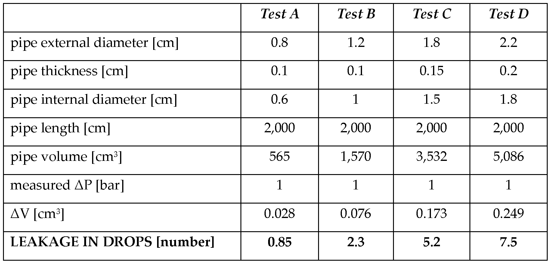
Further distinctive features of technical improvement compared with the known solutions concern the cheapness, the simplicity of construction, the operative precision, the high reliability and accuracy of the method and of the relevant apparatus according to the present invention.
In short, the advantages of the method and of the relevant apparatus according to the present invention reside in:
1) the abatement of costs originating from the oil leakages of the hydraulic circuits,
2) the reduction of the regeneration costs of the emulsion baths,
3) the reduction of the disposal costs of the waste oils,
4) the lifetime lengthening of the hydraulic circuits and of the users inserted therein,
5) the reduction of the number of machine stops, thanks to the possibility of timely scheduling preventive maintenance interventions,
6) the decrease of the fluids operating temperature due to the reduction of leakages, and 7) the greater availability of hydraulic power with improvement of the equipment performance.
On the basis of the foregoing, it is understood therefore that the method, and the relevant apparatus, for the remote detection of leakages in a hydraulic circuit, according to the present invention achieve the objects and accomplishes the advantages mentioned hereinabove.
It is finally clear that many other variants may be made to the method, and to the relevant apparatus, for the remote detection of leakages in a hydraulic circuit of the invention, without falling outside the novelty principles inherent in the inventive idea, as well as it is clear that in the practical implementation of the invention, the materials, the shapes and the dimensions of the illustrated details can be of any type, depending on requirements, and may be replaced with technically equivalent others.
Where the construction characteristics and the techniques mentioned in the following claims are followed by signs or reference numbers, these signs or reference numbers have been introduced with the sole purpose of increasing the intelligibility of the claims themselves and, consequently, they do not have any limiting effect on the interpretation of each element identified, by way of mere example, by such signs or reference numbers.
Claims
1. A method for the remote detection of leakages (L) in a hydraulic circuit (C) comprising the steps of:
- intercepting a portion (10) of said hydraulic circuit (C), to be subjected to the detection operations, by means of a first (1) and a second (2) pressure plug (step 201),
- connecting said portion of hydraulic circuit (10), specifically said first (1) and said second (2) pressure plug, to corresponding first (5) and second (6) end of an apparatus (20) suitable for the remote detection of said leakages (L), by means of corresponding first (3) and second (4) duct (step 202),
- starting said apparatus (20) (step 203),
- removing possible air (A) present in said portion of hydraulic circuit (10) by feeding into it a hydraulic fluid (F) and compressing said hydraulic fluid (F) (step 204),
- increasing the pressure of said hydraulic fluid (F) in said portion of hydraulic circuit (10) up to the operating reference value typical of said hydraulic circuit (C) to be checked (step 205),
- monitoring, for a predetermined period of time, that the pressure level is stabilized at said typical operating reference value (step 206),
- measuring the pressure values (PI, P2) in correspondence of said first (1) and said second (2) pressure plug, and determining the pressure gradient (ΔΡ) (step 207), generating an alarm signal in the event that said pressure gradient (ΔΡ) is higher than a predetermined value, preferably is higher than zero, this denoting the presence of a leakage (L) (step 208).
2. A method for the remote detection of leakages (L) according to claim 1, wherein said portion of hydraulic circuit (10) comprises an actuator (40), comprising in turn a first (41) and a second (42) chamber, said method comprising the steps of:
- measuring the pressure values (Ρ , P2') in correspondence of said first (41) and said second (42) chamber of said actuator (40), and determining the pressure gradient (ΔΡ') (step 207'),
- generating an alarm signal in the event that said pressure gradient (ΔΡ') is higher than a predetermined value, preferably is higher than zero, this denoting the presence
of a localized internal leakage (L), or internal leakage, between said two chambers (41, 42) (step 208')·
3. A method for the remote detection of leakages (L) according to claim 1 or 2, wherein said portion of hydraulic circuit (10) comprises an actuator (40), comprising in turn a first (41) and a second (42) chamber, said method comprising the steps of:
- measuring the pressure values (PI", P2") in correspondence of said second chamber (42) of said actuator (40) and said second pressure plug (2), and determining the pressure gradient (ΔΡ") (step 207"),
- generating an alarm signal in the event that said pressure gradient (ΔΡ") is higher than a predetermined value, preferably is higher than zero, this denoting the presence of a localized external leakage (L), or external leakage, between said second chamber (42) of said actuator (40) and said portion (10) of said hydraulic circuit (C) (step 208").
4. A method for the remote detection of leakages (L) according to claim 1 or 2 or 3, further comprising the step of:
- in the event that the presence of a leakage (L) has been detected in said portion of hydraulic circuit (10), determining the value of the flow rate of said leakage (L) (step 209).
5. A method for the remote detection of leakages (L) according to any of the preceding claims, further comprising the step of:
- automatically replenishing said leakage (L) in said portion of hydraulic circuit (10), by injecting in said portion of hydraulic circuit (10) a quantity of hydraulic fluid (F) equal to the value of the flow rate of said leakage (L), or anyhow sufficient to compensate said leakage (L) (step 210).
6. A method for the remote detection of leakages (L) according to any of the preceding claims, further comprising the steps of:
- draining said hydraulic fluid (F) by reducing the pressure in said portion of hydraulic circuit (10) (step 211),
- removing said pressure plugs (1, 2), thus restoring the operative condition of said hydraulic circuit (C) (step 212).
7. A method for the remote detection of leakages (L) according to any of the preceding claims, wherein said predetermined period of time for the stabilization of the pressure level is equal to 2 minutes.
8. A method for the remote detection of leakages (L) according to any of the preceding claims, wherein said predetermined value of pressure gradient (ΔΡ, ΔΡ', ΔΡ") is equal to 0.5 bar, i.e. 50 kPa.
9. A method for the remote detection of leakages (L) according to any of the preceding claims, wherein said flow rate of said leakage (L) is lower than 0.05 ml.
10. A method for the remote detection of leakages (L) according to any of the preceding claims, wherein said detection operations are carried out in static conditions, i.e. the hydraulic circuit (C) being under non-operative conditions.
11. An apparatus (20) for the remote detection of leakages (L) in a hydraulic circuit (C) comprising:
- a casing (21),
- a first (5) and a second (6) end suitable to be connected, by means of corresponding first (3) and second (4) duct, to a first (1) and a second (2) pressure plug that intercept a portion (10) of said hydraulic circuit (C), to be subjected to the detection operations,
- a tank (30) for a hydraulic fluid (F),
- a feeding system (22) for feeding said hydraulic fluid (F) into said portion of hydraulic circuit (10),
- a compression system (24) for removing possible air (A) present in said portion of hydraulic circuit (10) and for increasing the pressure of said hydraulic fluid (F) in said portion of hydraulic circuit (10) up to the operating reference value typical of said hydraulic circuit (C) to be checked,
- a control unit (23) for monitoring, for a predetermined period of time, that the pressure level is stabilized at said typical operating reference value,
- a system for measuring pressure (25) for measuring the pressure values (PI, P2) in correspondence of said first (1) and said second (2) pressure plug, and for determining the pressure gradient (ΔΡ),
- an alarm device (27) suitable to be activated in the event that said pressure gradient (ΔΡ) is higher than a predetermined value, preferably is higher than zero, this denoting the presence of a leakage (L).
12. An apparatus (20) for the remote detection of leakages (L) according to claim 11, wherein said portion of hydraulic circuit (10) comprises an actuator (40), comprising in turn a first (41) and a second (42) chamber, said apparatus (20) further comprising:
- a system for measuring pressure (25') for measuring the pressure values (Ρ , P2') in correspondence of said first (41) and said second (42) chamber of said actuator (40), and for determining the pressure gradient (ΔΡ').
13. An apparatus (20) for the remote detection of leakages (L) according to claim 11 or 12, wherein said portion of hydraulic circuit (10) comprises an actuator (40), comprising in turn a first (41) and a second ( 42) chamber, said apparatus (20) further comprising:
- a system for measuring pressure (25") for measuring the pressure values (PI", P2") in correspondence of said second chamber (42) of said actuator (40) and said second pressure plug (2), and for determining the pressure gradient (ΔΡ").
14. An apparatus (20) for the remote detection of leakages (L) according to claim 11 or 12 or 13, further comprising:
- a system for determining a flow rate (26) for determining the value of the flow rate of the leakage (L) detected in said portion of hydraulic circuit (10).
15. An apparatus (20) for the remote detection of leakages (L) according to any claim 11 to 14, further comprising:
- a system for automatically replenishing (29) the detected leakages (L) suitable to receive, through a drive system (39), the value of the flow rate of said leakage (L) detected in said portion of hydraulic circuit (10) and to transmit said value to an injector, included in said system for automatically replenishing (29), that, so activated, automatically replenishes said portion of hydraulic circuit (10) with a quantity of hydraulic fluid (F) equal to the value of the flow rate of said leakage (L), or anyhow sufficient to compensate said leakage (L).
16. An apparatus (20) for the remote detection of leakages (L) according to any claim 11 to 15, further comprising:
- a system (28) for draining said hydraulic fluid (F) from said portion of hydraulic circuit (10).
Applications Claiming Priority (2)
| Application Number | Priority Date | Filing Date | Title |
|---|---|---|---|
| ITTO20140237 | 2014-03-21 | ||
| ITTO2014A000237 | 2014-03-21 |
Publications (1)
| Publication Number | Publication Date |
|---|---|
| WO2015140609A1 true WO2015140609A1 (en) | 2015-09-24 |
Family
ID=50943479
Family Applications (1)
| Application Number | Title | Priority Date | Filing Date |
|---|---|---|---|
| PCT/IB2014/066386 WO2015140609A1 (en) | 2014-03-21 | 2014-11-27 | Method for the remote detection of leakages in hydraulic circuits, and apparatus thereof |
Country Status (1)
| Country | Link |
|---|---|
| WO (1) | WO2015140609A1 (en) |
Citations (3)
| Publication number | Priority date | Publication date | Assignee | Title |
|---|---|---|---|---|
| DE2603715A1 (en) * | 1976-01-31 | 1977-08-11 | Rolf Prof Dr Ing Isermann | Pipeline leakage detection and location - by measuring pressure gradients on section ends and pressure differential using stated formula |
| JPS5879133A (en) * | 1981-11-05 | 1983-05-12 | Kubota Ltd | Water pressure testing method |
| EP1007931B1 (en) | 1997-05-06 | 2003-07-30 | Paul Lander | Improved method for detecting leaks in pipelines |
-
2014
- 2014-11-27 WO PCT/IB2014/066386 patent/WO2015140609A1/en active Application Filing
Patent Citations (3)
| Publication number | Priority date | Publication date | Assignee | Title |
|---|---|---|---|---|
| DE2603715A1 (en) * | 1976-01-31 | 1977-08-11 | Rolf Prof Dr Ing Isermann | Pipeline leakage detection and location - by measuring pressure gradients on section ends and pressure differential using stated formula |
| JPS5879133A (en) * | 1981-11-05 | 1983-05-12 | Kubota Ltd | Water pressure testing method |
| EP1007931B1 (en) | 1997-05-06 | 2003-07-30 | Paul Lander | Improved method for detecting leaks in pipelines |
Similar Documents
| Publication | Publication Date | Title |
|---|---|---|
| CN103807607A (en) | Novel device and method for detecting leakage of fluids in pipelines | |
| NO20150004A1 (en) | Method and apparatus for detecting fluid leakage between two pipe sections | |
| CN101349608A (en) | Method and apparatus for detecting pressure vessel air tightness | |
| CN107884008B (en) | Method for testing sealing performance of metal hose under axial tension and corrosion state | |
| EP1846742A2 (en) | Fluid containment element leak detection apparatus and method | |
| CN105181271A (en) | Relief device for pipeline leakage monitoring system performance test and testing method | |
| CN207074106U (en) | A kind of double-piston valve leakage detection apparatus | |
| US20170082517A1 (en) | Leak detection system | |
| WO2015140609A1 (en) | Method for the remote detection of leakages in hydraulic circuits, and apparatus thereof | |
| US11326978B2 (en) | Leak indicating clamp | |
| CN205173992U (en) | Relief valve dismouting replacement detection device | |
| GB2517411A (en) | Monitoring pipelines | |
| CN105387558A (en) | Chilled water tail end system and fault detection method thereof | |
| Xu et al. | Leak detection methods overview and summary | |
| US11359748B2 (en) | Connection system between a distribution member and a receiving member and leak detection method | |
| Zhang et al. | Development of low-cost air-based hydraulic leakage detection system through real-time pressure decay data acquisition technology | |
| KR20160001307U (en) | Apparatus for detectiing leak gas of heating medium system | |
| CN108368808B (en) | Leak detection device | |
| CN205388531U (en) | Large -scale aqueous vapor solenoid valve detecting system that synthesizes | |
| CN204085808U (en) | A kind of air-tightness detection device | |
| JP2002333381A (en) | Detection method for leak of hydrogen gas | |
| US9684293B2 (en) | Refrigerant relief valve monitoring system and method | |
| CN204405274U (en) | A kind of device suppressing instrument for the connection of multiple spot stagnation pressure tube | |
| CN202469496U (en) | Beam tube leak detector | |
| KR102368572B1 (en) | Gas leak detection system and gas leak detection method |
Legal Events
| Date | Code | Title | Description |
|---|---|---|---|
| 121 | Ep: the epo has been informed by wipo that ep was designated in this application |
Ref document number: 14821847 Country of ref document: EP Kind code of ref document: A1 |
|
| NENP | Non-entry into the national phase |
Ref country code: DE |
|
| 122 | Ep: pct application non-entry in european phase |
Ref document number: 14821847 Country of ref document: EP Kind code of ref document: A1 |