WO2015137341A1 - Light projection device and light projection method - Google Patents
Light projection device and light projection method Download PDFInfo
- Publication number
- WO2015137341A1 WO2015137341A1 PCT/JP2015/057018 JP2015057018W WO2015137341A1 WO 2015137341 A1 WO2015137341 A1 WO 2015137341A1 JP 2015057018 W JP2015057018 W JP 2015057018W WO 2015137341 A1 WO2015137341 A1 WO 2015137341A1
- Authority
- WO
- WIPO (PCT)
- Prior art keywords
- light projecting
- light
- unit
- projection
- shape
- Prior art date
Links
Images


Classifications
-
- G—PHYSICS
- G03—PHOTOGRAPHY; CINEMATOGRAPHY; ANALOGOUS TECHNIQUES USING WAVES OTHER THAN OPTICAL WAVES; ELECTROGRAPHY; HOLOGRAPHY
- G03B—APPARATUS OR ARRANGEMENTS FOR TAKING PHOTOGRAPHS OR FOR PROJECTING OR VIEWING THEM; APPARATUS OR ARRANGEMENTS EMPLOYING ANALOGOUS TECHNIQUES USING WAVES OTHER THAN OPTICAL WAVES; ACCESSORIES THEREFOR
- G03B21/00—Projectors or projection-type viewers; Accessories therefor
- G03B21/14—Details
- G03B21/147—Optical correction of image distortions, e.g. keystone
-
- G—PHYSICS
- G03—PHOTOGRAPHY; CINEMATOGRAPHY; ANALOGOUS TECHNIQUES USING WAVES OTHER THAN OPTICAL WAVES; ELECTROGRAPHY; HOLOGRAPHY
- G03B—APPARATUS OR ARRANGEMENTS FOR TAKING PHOTOGRAPHS OR FOR PROJECTING OR VIEWING THEM; APPARATUS OR ARRANGEMENTS EMPLOYING ANALOGOUS TECHNIQUES USING WAVES OTHER THAN OPTICAL WAVES; ACCESSORIES THEREFOR
- G03B17/00—Details of cameras or camera bodies; Accessories therefor
- G03B17/48—Details of cameras or camera bodies; Accessories therefor adapted for combination with other photographic or optical apparatus
- G03B17/54—Details of cameras or camera bodies; Accessories therefor adapted for combination with other photographic or optical apparatus with projector
-
- G—PHYSICS
- G03—PHOTOGRAPHY; CINEMATOGRAPHY; ANALOGOUS TECHNIQUES USING WAVES OTHER THAN OPTICAL WAVES; ELECTROGRAPHY; HOLOGRAPHY
- G03B—APPARATUS OR ARRANGEMENTS FOR TAKING PHOTOGRAPHS OR FOR PROJECTING OR VIEWING THEM; APPARATUS OR ARRANGEMENTS EMPLOYING ANALOGOUS TECHNIQUES USING WAVES OTHER THAN OPTICAL WAVES; ACCESSORIES THEREFOR
- G03B21/00—Projectors or projection-type viewers; Accessories therefor
- G03B21/54—Accessories
-
- H—ELECTRICITY
- H04—ELECTRIC COMMUNICATION TECHNIQUE
- H04N—PICTORIAL COMMUNICATION, e.g. TELEVISION
- H04N9/00—Details of colour television systems
- H04N9/12—Picture reproducers
- H04N9/31—Projection devices for colour picture display, e.g. using electronic spatial light modulators [ESLM]
- H04N9/3179—Video signal processing therefor
- H04N9/3185—Geometric adjustment, e.g. keystone or convergence
Abstract
A light projection device according to the present invention is equipped with: a light projection unit provided with a light projection optical system for projecting light, the light projection unit projecting light of a prescribed shape to an object to which light is to be projected; a position detection unit for detecting the three-dimensional position of the object to which light is to be projected; a light projection direction change unit for changing the direction of the light projected by the light projection unit; a light projection direction control unit for making the light projection direction change unit change the direction of the projected light and having the light projected to the object to which light is to be projected at a position detected by the position detection unit; a shape calculation unit for calculating the shape of the light projected to the surface of the object to which light is to be projected at a position detected by the position detection unit; and a shape control unit for making the light projection unit project light of the shape calculated by the shape calculation unit.
Description
本発明は、物体表面に所定形状の光を投影する投光装置に関するものである。
The present invention relates to a light projecting device that projects light of a predetermined shape onto the surface of an object.
近年、建築物や家具などの立体物、又は、凹凸のある面に、映像やコンピュータグラフィックス等を投影する、いわゆる、プロジェクションマッピングが行われている。プロジェクションマッピングは、実物と映像とをシンクロさせる映像手法であることから、実物と映像との融合が生み出す魅力的な世界観がある。
In recent years, so-called projection mapping has been performed in which images, computer graphics, and the like are projected onto a three-dimensional object such as a building or furniture, or an uneven surface. Projection mapping is a video technique that synchronizes the real and the video, so there is an attractive world view created by the fusion of the real and the video.
プロジェクションマッピングでは、映像を投影した際に、投影した映像が投影対象物である立体物にぴたりと重なる映像となるように、投影対象物である立体物の表面形状等に応じて、投影する映像が変更される。投影対象物である立体物と重なっている映像に動きや変化が生じることで、その立体物が動いたり、変形したり、又は、自ら光を放つように見る者に感じさせる、幻想的で錯覚的な映像が表現される。
In projection mapping, a projected image is projected according to the surface shape of the three-dimensional object that is the projection target so that when the image is projected, the projected image is exactly superimposed on the three-dimensional object that is the projection target Is changed. Fantastic and illusion that makes the viewer feel as if the three-dimensional object moves, deforms, or emits light by moving or changing the image that overlaps the three-dimensional object that is the projection target. Realistic images are expressed.
ここで、投影対象物として、建築物や家具等の、いわゆる静的な物体にとどまらず、動的な(移動する)物体にも、プロジェクションマッピングを行いたいという要望が出てきており、様々な技術が提案されている。例えば、投影対象物からカメラに入射する光の光軸とプロジェクタから投影される光の光軸とを一致させ、カメラによる撮像画像内の投影対象物の位置が予め定められている位置から離れている場合は、その予め定められている位置に近づくように、プロジェクタの投影方向を制御する技術がある(特許文献1参照)。
Here, there is a demand for performing projection mapping not only on so-called static objects such as buildings and furniture but also on dynamic (moving) objects as projection objects. Technology has been proposed. For example, the optical axis of light incident on the camera from the projection object is matched with the optical axis of light projected from the projector, and the position of the projection object in the image captured by the camera is separated from a predetermined position. If it is, there is a technique for controlling the projection direction of the projector so as to approach the predetermined position (see Patent Document 1).
しかし、上記特許文献1の技術は、カメラとプロジェクタの各光軸を互いに一致させる必要がある。また、上記特許文献1の技術は、投影対象物の移動速度が速く、カメラの撮像画像内に写っていない場合には、プロジェクタの投光方向を制御することができない。
However, the technique disclosed in Patent Document 1 requires that the optical axes of the camera and the projector coincide with each other. Further, the technique disclosed in Patent Document 1 cannot control the light projecting direction of the projector when the moving speed of the projection target is fast and is not captured in the captured image of the camera.
また、プロジェクションマッピングでは、投影対象物の表面形状に応じて、投影する映像が変更される必要があり、この処理に時間がかかる場合には、対象物の移動に映像の変更が追い付かずに映像が対象物にマッピングされなくなる可能性がある。
Also, in projection mapping, the projected image needs to be changed according to the surface shape of the projection object. If this process takes time, the image will not catch up with the movement of the object. May not be mapped to the object.
本発明は、上述の事情に鑑みて為された発明であり、本発明は、移動する対象物に、所定形状の光(映像)を投光することができる投光装置及び該方法を提供することを目的とする。
The present invention is an invention made in view of the above-described circumstances, and the present invention provides a light projecting apparatus and a method capable of projecting light (video) having a predetermined shape onto a moving object. For the purpose.
本発明に係る投光装置は、光を投光する投光光学系を有し、投光対象物に所定形状の光を投光する投光部と、前記投光対象物の3次元位置を検出する位置検出部と、前記投光部の前記投光方向を変更する投光方向変更部と、前記投光方向変更部に前記投光方向を変更させて、前記位置検出部が検出した位置の前記投光対象物に光を投光させる投光方向制御部と、前記位置検出部が検出した位置の前記投光対象物の表面に投光する光の形状を算出する形状算出部と、前記形状算出部が算出した形状の光を、前記投光部に投光させる形状制御部とを備える。そのため、投光対象物が移動した場合に、迅速に、投光対象物に投光することが可能となる。
The light projecting device according to the present invention includes a light projecting optical system that projects light, a light projecting unit that projects light of a predetermined shape onto the light projecting object, and a three-dimensional position of the light projecting object. A position detecting unit to detect, a light projecting direction changing unit for changing the light projecting direction of the light projecting unit, and a position detected by the position detecting unit by causing the light projecting direction changing unit to change the light projecting direction. A projection direction control unit that projects light onto the projection target object, a shape calculation unit that calculates the shape of light projected onto the surface of the projection target object at the position detected by the position detection unit, A shape control unit that causes the light projecting unit to project light having the shape calculated by the shape calculating unit. Therefore, when the light projecting object moves, it is possible to quickly project the light projecting object.
上記並びにその他の本発明の目的、特徴及び利点は、以下の詳細な記載と添付図面から明らかになるであろう。
The above and other objects, features and advantages of the present invention will become apparent from the following detailed description and the accompanying drawings.
<実施形態1>
以下、本発明の一実施の形態における投光装置について説明する。尚、各図において同一の符号を付した構成は、同一の構成であることを示し、適宜、その説明を省略する。本明細書において、総称する場合には添え字を省略した参照符号で示し、個別の構成を指す場合には添え字を付した参照符号で示す。 <Embodiment 1>
Hereinafter, a projector according to an embodiment of the present invention will be described. In addition, the structure which attached | subjected the same code | symbol in each figure shows that it is the same structure, The description is abbreviate | omitted suitably. In this specification, when referring generically, it shows with the reference symbol which abbreviate | omitted the suffix, and when referring to an individual structure, it shows with the reference symbol which attached the suffix.
以下、本発明の一実施の形態における投光装置について説明する。尚、各図において同一の符号を付した構成は、同一の構成であることを示し、適宜、その説明を省略する。本明細書において、総称する場合には添え字を省略した参照符号で示し、個別の構成を指す場合には添え字を付した参照符号で示す。 <
Hereinafter, a projector according to an embodiment of the present invention will be described. In addition, the structure which attached | subjected the same code | symbol in each figure shows that it is the same structure, The description is abbreviate | omitted suitably. In this specification, when referring generically, it shows with the reference symbol which abbreviate | omitted the suffix, and when referring to an individual structure, it shows with the reference symbol which attached the suffix.
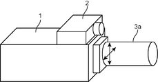
図1は、本発明の実施の形態による投光装置100の機能ブロックの例を示す図である。図2は、投光装置100の外観図を示し、図3、4は、後述する投光部3の例を示し、図5は、投光方向変更部4の一例を示す。
FIG. 1 is a diagram illustrating an example of functional blocks of a light projecting device 100 according to an embodiment of the present invention. 2 shows an external view of the light projecting device 100, FIGS. 3 and 4 show an example of a light projecting unit 3 to be described later, and FIG. 5 shows an example of a light projecting direction changing unit 4.
投光装置100は、投光本体部1、位置検出部2、投光部3、投光方向変更部4、及び、インタフェース部5を備える。投光装置100は、外部の映像コンテンツ記憶部6から映像を取得して、投光対象物Obに対して、取得した映像に基づく映像を投光する装置である。
The light projecting device 100 includes a light projecting main body unit 1, a position detecting unit 2, a light projecting unit 3, a light projecting direction changing unit 4, and an interface unit 5. The light projecting device 100 is a device that acquires a video from the external video content storage unit 6 and projects a video based on the acquired video to the projection target object Ob.
投光本体部1は、投光装置100の全体制御を行うものであり、映像コンテンツ取得部11、画像処理部12(形状算出部)、映像表示制御部13(形状制御部)、投光方向制御部14を備える。
The light projecting body unit 1 performs overall control of the light projecting device 100, and includes a video content acquisition unit 11, an image processing unit 12 (shape calculation unit), a video display control unit 13 (shape control unit), and a light projection direction. A control unit 14 is provided.
映像コンテンツ取得部11は、映像コンテンツ記憶部6から映像を取得する。映像コンテンツ記憶部6は、例えば、USB(Universal Serial Bus)メモリ等の可搬性の記録媒体であり、映像コンテンツ取得部11は、その記録媒体に応じた接続部を含み、読み書き機能を実現するドライバである。
The video content acquisition unit 11 acquires video from the video content storage unit 6. The video content storage unit 6 is a portable recording medium such as a USB (Universal Serial Bus) memory, for example, and the video content acquisition unit 11 includes a connection unit corresponding to the recording medium and implements a read / write function. It is.
画像処理部12は、映像コンテンツ取得部11が取得した映像から、映像表示制御部13の指示に応じて変更した映像を生成する。画像処理部12は、例えば、投光対象物Obの形状の変化(例えば、回転)に合わせて映像の形状を変形したり、投光対象物Obまでの距離に応じて映像の大きさを変更したり、台形補正、輝度補正等の必要な算出処理を行う。画像処理部12は、形状変形処理部121を備える。形状変形処理部121は、画像処理部12が行う画像処理の一部の処理、例えば、投光対象物Obの見た目の形状に合わせて映像の形状を変更する処理を行う。尚、実施形態では、形状変形処理部121は、画像処理の一部の処理として映像の形状を変形するように構成されているが、一部の処理であればよく、画像処理によって光の形状を変更する場合は、その一部の処理として、例えば、回転を行わない等の大まかな形状変更を行うように構成されてもよい。
The image processing unit 12 generates a video that has been changed according to an instruction from the video display control unit 13 from the video acquired by the video content acquisition unit 11. For example, the image processing unit 12 changes the shape of the image in accordance with a change (for example, rotation) of the shape of the projection object Ob, or changes the size of the image according to the distance to the projection object Ob. Or perform necessary calculation processing such as keystone correction and luminance correction. The image processing unit 12 includes a shape deformation processing unit 121. The shape transformation processing unit 121 performs a part of the image processing performed by the image processing unit 12, for example, a process of changing the shape of the video in accordance with the appearance of the projected object Ob. In the embodiment, the shape deformation processing unit 121 is configured to deform the shape of the video as a part of the image processing. In the case of changing, for example, a rough shape change such as no rotation may be performed as part of the processing.
映像表示制御部13は、位置検出部2が検出した投光対象物Obの位置座標(x,y,z)に応じた画像処理を画像処理部12に指示し、画像処理部12による画像処理後の映像を、投光部3に投光させる。例えば、映像表示制御部13は、透過型の液晶パネルと光源を有し、液晶パネルに映像を表示し、光源からの照射光を透過させ、透過光を投光部3に出力する。映像表示制御部13は、インタフェース部5を介してユーザから同期処理を指示されている場合は、映像表示制御部13による画像処理の終了を投光方向制御部14に対して通知する。同期処理は、<追従処理>の項で説明される。
The video display control unit 13 instructs the image processing unit 12 to perform image processing according to the position coordinates (x, y, z) of the projection object Ob detected by the position detection unit 2, and image processing by the image processing unit 12 is performed. The subsequent image is projected to the light projecting unit 3. For example, the video display control unit 13 includes a transmissive liquid crystal panel and a light source, displays video on the liquid crystal panel, transmits irradiation light from the light source, and outputs the transmitted light to the light projecting unit 3. The video display control unit 13 notifies the projection direction control unit 14 of the end of the image processing by the video display control unit 13 when the synchronization processing is instructed by the user via the interface unit 5. The synchronization process is described in the section <Follow-up process>.
投光方向制御部14は、位置検出部2が検出した投光対象物Obの位置に、投光部3の投光方向を向けるよう、投光方向変更部4に指示する。
The light projecting direction control unit 14 instructs the light projecting direction changing unit 4 to direct the light projecting direction of the light projecting unit 3 to the position of the light projecting object Ob detected by the position detecting unit 2.
位置検出部2は、所定の周期で、投光対象物Obの位置座標(例えば、ワールド座標系の座標)を繰り返し検出し、映像表示制御部13及び投光方向制御部14に出力する。位置検出部2は、例えば、IR(赤外線)カメラであり、光源とイメージセンサを有し、光源からの照射光が投光対象物Obにより反射されて戻ってくるまでの時間を測定し、投光対象物Obの距離画像を作成する。位置検出部2は、IRカメラに限らず、例えば、ステレオカメラであり、ステレオ画像の視差を用いた測距方法により、投光対象物Obの位置座標を検出してもよい。尚、実施形態では、図2に示すように、IRカメラ(位置検出部2)は、プロジェクタ本体(投光本体部1)の上面に設置されているものとするが、この位置に限らず、内蔵されてもよく、また、プロジェクタ本体とは離れた場所に設置されてもよい。IRカメラ(位置検出部2)は、投光対象物Obの位置が検出できる場所に設置されればよい。この場合、IRカメラ(位置検出部2)とプロジェクタ本体(投光本体部1)とは、位置検出部2が検出した位置座標を送受信する機能を有する。尚、位置検出部2を投光装置100に搭載することにより、持ち運び等の操作性が向上し、位置検出部2と投光部3の投光方向をあわせておくこと、つまり、位置検出部2であるカメラを、投光対象物Obの方向に向けておくことが可能となる。
The position detection unit 2 repeatedly detects the position coordinates (for example, coordinates in the world coordinate system) of the projection object Ob at a predetermined cycle, and outputs the position coordinates to the video display control unit 13 and the projection direction control unit 14. The position detection unit 2 is, for example, an IR (infrared) camera, and includes a light source and an image sensor. The position detection unit 2 measures the time until the irradiation light from the light source is reflected by the projection object Ob and returns. A distance image of the light object Ob is created. The position detection unit 2 is not limited to the IR camera, and may be a stereo camera, for example, and may detect the position coordinates of the projection object Ob by a distance measuring method using parallax of a stereo image. In the embodiment, as shown in FIG. 2, the IR camera (position detecting unit 2) is installed on the upper surface of the projector main body (projecting main body unit 1). It may be built in or may be installed at a location away from the projector body. The IR camera (position detection unit 2) may be installed in a place where the position of the projection object Ob can be detected. In this case, the IR camera (position detecting unit 2) and the projector main body (light projecting main unit 1) have a function of transmitting and receiving position coordinates detected by the position detecting unit 2. Incidentally, by mounting the position detection unit 2 on the light projecting device 100, the operability such as carrying is improved, and the light projection directions of the position detection unit 2 and the light projection unit 3 are matched, that is, the position detection unit. 2 can be directed toward the light projecting object Ob.
投光部3は、投光光学系31を有し、映像表示制御部13から入力した映像を投光対象物Obに投影する。投光光学系31は、光軸に沿って1又は複数の光学レンズであるレンズ群を、1又は複数備えて構成され、更に、必要に応じて、ミラー等を有してもよい。
The light projecting unit 3 has a light projecting optical system 31 and projects the video input from the video display control unit 13 onto the light projecting object Ob. The light projecting optical system 31 includes one or a plurality of lens groups that are one or a plurality of optical lenses along the optical axis, and may further include a mirror or the like as necessary.
投光方向変更部4は、投光部3の投光方向を、投光方向制御部14の指示に応じて変更(補正)する。実施形態では、次の4つの方法で投光方向を変更する。
The light projecting direction changing unit 4 changes (corrects) the light projecting direction of the light projecting unit 3 in accordance with an instruction from the light projecting direction control unit 14. In the embodiment, the light projection direction is changed by the following four methods.
1つは、図2に示すように、投光部3の一例である鏡胴3a自体が、矢印方向(投光部3の光軸に対し直交するとともに互いに直交する2方向の水平方向又は垂直方向)にシフトされることで投光方向が変更される。この場合の投光方向変更部4は、鏡胴をシフトさせるための、圧電素子を用いたアクチュエータやボイスコイルを用いたアクチュエータ等の駆動装置である。尚、鏡胴3aのシフト方向は、矢印方向に限られず、投光部3の光軸に対し直交する方向であればよい。
First, as shown in FIG. 2, the lens barrel 3a itself, which is an example of the light projecting unit 3, has two horizontal directions or vertical directions in the direction of the arrows (perpendicular to the optical axis of the light projecting unit 3 and perpendicular to each other. The projection direction is changed by shifting to (direction). The light projecting direction changing unit 4 in this case is a drive device such as an actuator using a piezoelectric element or an actuator using a voice coil for shifting the lens barrel. The shift direction of the lens barrel 3a is not limited to the arrow direction, and may be a direction orthogonal to the optical axis of the light projecting unit 3.
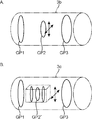
2つ目は、図3に示すように、鏡胴(投光部3)内のレンズ群(投光光学系31)が、矢印方向(投光光学系31の光軸に対し直交するとともに互いに直交する2方向の水平方向又は垂直方向)にシフトされることで投光方向が変更される。図3Aの鏡胴3bは、投光光学系31として、それぞれ1つの光学レンズから成る3つのレンズ群GP1、GP2、GP3を備え、レンズ群GP2が必要に応じてシフトされる。また、図3Bの鏡胴3cは、3つのレンズ群のうちレンズ群GP1、G3は、1つの光学レンズから成り、レンズ群GP2´は、複数の光学レンズから成り、レンズ群GP2´は、レンズ群ごとシフトされる。この場合の投光方向変更部4は、レンズ群をシフトさせるための駆動装置である。尚、レンズ群GP2、GP2´のシフト方向は、矢印方向に限られず、投光光学系31の光軸に対し直交する方向であればよい。
Second, as shown in FIG. 3, the lens group (projecting optical system 31) in the lens barrel (projecting unit 3) is perpendicular to the optical axis of the projecting optical system 31 and is mutually orthogonal. The light projection direction is changed by shifting in two orthogonal directions (horizontal direction or vertical direction). The lens barrel 3b of FIG. 3A includes three lens groups GP1, GP2, and GP3 each including one optical lens as the light projecting optical system 31, and the lens group GP2 is shifted as necessary. The lens barrel 3c in FIG. 3B includes lens groups GP1 and G3 among the three lens groups, each including one optical lens, the lens group GP2 ′ including a plurality of optical lenses, and the lens group GP2 ′ including the lens group GP2 ′. Shifted by group. The light projecting direction changing unit 4 in this case is a driving device for shifting the lens group. The shift direction of the lens groups GP2 and GP2 ′ is not limited to the arrow direction, and may be a direction orthogonal to the optical axis of the light projecting optical system 31.
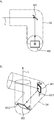
3つ目は、図4に示すように、鏡胴(投光部3)内のミラー(投光光学系31)が回転されることで投光方向が変更される。図4Aは、投光光学系31として、ミラーM1とミラーM2とを備える鏡胴3dを、投光対象物Ob側から見た正面図である。図4Bは、鏡胴3dの斜視図である。
Third, as shown in FIG. 4, the light projection direction is changed by rotating the mirror (light projection optical system 31) in the lens barrel (light projection unit 3). FIG. 4A is a front view of the lens barrel 3d including the mirror M1 and the mirror M2 as the light projecting optical system 31 as viewed from the light projecting object Ob side. FIG. 4B is a perspective view of the lens barrel 3d.
鏡胴3dは、第1円筒部、第2円筒部、第3円筒部の3つの円筒部が連結して成る。第1円筒部の他方端と第2円筒部の一方端とが、各円筒部の中心軸が直交するように第1連結部で連結される。第2円筒部の他方端と第3円筒部の一方端とが、各円筒部の中心軸が直交し、かつ、第3円筒部の中心軸が、第1円筒部の中心軸と第2円筒部の中心軸とで構成される平面の法線と一致するように、第2連結部で連結される。第1連結部には、第1円筒部の中心軸と第2円筒部の中心軸とで構成される平面の法線と一致する方向の回転軸AX1を持つミラーM1が設置され、第2連結部には、第2円筒部の中心軸と第3円筒部の中心軸とで構成される平面の法線と一致する方向の回転軸AX2を持つミラーM2が設置される。光束Lは、第1円筒部の一方端から入射し、ミラーM1で反射されてミラーM2に入射し、ミラー2で反射されて、第3円筒部の他方端から出射する。ミラーM1、M2が、それぞれの回転軸AX1、AX2を中心として所定角度で回転されることで、光束Lの出射方向が変更される。この場合の投光方向変更部4は、ミラーを回転させる駆動装置である。
The lens barrel 3d is formed by connecting three cylindrical portions, a first cylindrical portion, a second cylindrical portion, and a third cylindrical portion. The other end of the first cylindrical portion and the one end of the second cylindrical portion are connected by the first connecting portion so that the central axes of the respective cylindrical portions are orthogonal to each other. The other end of the second cylindrical portion and the one end of the third cylindrical portion are perpendicular to the central axis of each cylindrical portion, and the central axis of the third cylindrical portion is the central axis of the first cylindrical portion and the second cylinder. They are connected by the second connecting part so as to coincide with the normal line of the plane constituted by the central axis of the part. The first connecting portion is provided with a mirror M1 having a rotation axis AX1 in a direction coinciding with a normal line of a plane formed by the central axis of the first cylindrical portion and the central axis of the second cylindrical portion, and the second connecting portion. A mirror M2 having a rotation axis AX2 in a direction coinciding with a normal line of a plane constituted by the central axis of the second cylindrical part and the central axis of the third cylindrical part is installed in the part. The light beam L is incident from one end of the first cylindrical portion, is reflected by the mirror M1, is incident on the mirror M2, is reflected by the mirror 2, and is emitted from the other end of the third cylindrical portion. As the mirrors M1 and M2 are rotated by a predetermined angle about the respective rotation axes AX1 and AX2, the emission direction of the light beam L is changed. The light projecting direction changing unit 4 in this case is a drive device that rotates the mirror.
4つ目は、図5に示すように、位置検出部2を備えた投光本体部1が、パンチルト雲台に搭載され、パンチルト雲台のパン駆動及びチルト駆動が行われることで、投光方向が変更される。パンチルト雲台は、パン駆動部41とチルト駆動部42とから成る。パン駆動部41は、パン回転軸AX41を軸中心としてパン方向(矢印参照)に回動する。チルト駆動部42は、パン回転軸AX41に直交するチルト回転軸42を軸中心としてチルト方向(矢印参照)に回動する。この場合の投光方向変更部4は、パンチルト雲台である。
Fourth, as shown in FIG. 5, the light projecting main body 1 having the position detection unit 2 is mounted on the pan / tilt head, and the pan / tilt head is driven to perform light projection. The direction is changed. The pan / tilt head includes a pan driving unit 41 and a tilt driving unit 42. The pan drive unit 41 rotates in the pan direction (see an arrow) about the pan rotation axis AX41. The tilt drive unit 42 rotates in the tilt direction (see an arrow) about the tilt rotation shaft 42 orthogonal to the pan rotation axis AX41. The light projecting direction changing unit 4 in this case is a pan / tilt head.
尚、図4、5で示した鏡胴(投光部)3b、3c、3dに、それぞれの投光方向変更部4(駆動装置)を内蔵することとすれば、投光装置100の鏡胴(投光部3)のみを交換することで、投光対象物Obまでの距離や環境、投光する映像等に応じた投光装置100とすることが可能となる。
4 and 5, if the respective light projecting direction changing units 4 (drive devices) are incorporated in the lens barrels (light projecting units) 3b, 3c, and 3d shown in FIGS. By exchanging only the (light projection unit 3), it is possible to obtain the light projection device 100 according to the distance to the light projection object Ob, the environment, the image to be projected, and the like.
インタフェース部5は、ユーザからの指示を投光装置100に入力する入力部と、投光装置100からのメッセージ等をユーザに通知する出力部とを有する。インタフェース部5は、例えば、タッチパネルである。タッチパネルにおいて、入力部は、例えば抵抗膜方式や静電容量方式等の操作位置を検出して入力する位置入力装置であり、出力部は、表示装置である。このタッチパネルでは、表示装置の表示面上には、ボタン等の入力可能な1または複数の入力内容の候補が表示され、ユーザが、入力したい入力内容を表示したボタンに触れると、そのボタンに表示された表示内容がユーザの操作入力内容として投光装置100に入力される。実施形態では、投光装置100は、<追従方法>の項で説明するように、移動体への投光方法(以下、「追従方法」ともいう。)として、2つの方法を備える。ユーザは、インタフェース部5を介して、いずれの追従方法を用いるかを投光装置100に指示する。
The interface unit 5 includes an input unit that inputs an instruction from the user to the light projecting device 100, and an output unit that notifies the user of a message or the like from the light projecting device 100. The interface unit 5 is, for example, a touch panel. In the touch panel, the input unit is a position input device that detects and inputs an operation position such as a resistance film method or a capacitance method, and the output unit is a display device. In this touch panel, one or a plurality of input content candidates that can be input such as buttons are displayed on the display surface of the display device, and when the user touches a button that displays the input content that the user wants to input, the button displays the input content. The displayed contents are input to the light projecting device 100 as user operation input contents. In the embodiment, the light projecting device 100 includes two methods as a light projecting method (hereinafter also referred to as “following method”) to the moving body, as described in the section <Following method>. The user instructs the light projecting device 100 through the interface unit 5 which tracking method to use.
尚、投光本体部1は、例えば、マイクロプロセッサ、メモリおよびその周辺回路を備えるマイクロコンピュータによって構成され、メモリには、画像処理を行うためのプログラムや、投光装置100全体を制御するための制御プログラム等の各種のプログラム、プログラムの実行に必要なデータ等の各種のデータが記憶され、いわゆるCPU(Central Processing Unit)等であるマイクロプロセッサが、メモリに記憶されているプログラムを実行することにより、各機能部の全部又は一部を実現する。
The light projecting main unit 1 is constituted by, for example, a microcomputer including a microprocessor, a memory, and peripheral circuits thereof. The memory is used for controlling a program for performing image processing and the entire light projecting device 100. Various programs such as control programs and various data such as data necessary for program execution are stored, and a microprocessor such as a so-called CPU (Central Processing Unit) executes a program stored in the memory. All or part of each functional unit is realized.
<追従処理>
投光装置100は、2つの追従方法を実行することができる。1つ目の方法は、位置検出部2が投光対象物Obの位置を検出する都度、投光部3の投光方向を投光対象物Obに向けることで、移動体を追従する方法である。2つ目の方法は、画像処理のうちの形状変形処理のみが終了した時点と、画像処理が完了した時点とで、投光部3の投光方向を投光対象物Obに向けることで移動体を追従する方法である。以下、1つ目の方法は「非同期方法」と呼称され、2つ目の方法は「同期方法」と呼称される。投光部3の投光方向を投光対象物Obに向けることは「光学補正」と呼称される。 <Follow-up processing>
The light projectingdevice 100 can execute two following methods. The first method is a method of following the moving body by directing the light projecting direction of the light projecting unit 3 toward the light projecting object Ob every time the position detecting unit 2 detects the position of the light projecting object Ob. is there. The second method is to move the light projecting direction of the light projecting unit 3 toward the light projecting object Ob between the time when only the shape deformation process of the image process is completed and the time when the image process is completed. It is a method of following the body. Hereinafter, the first method is referred to as “asynchronous method”, and the second method is referred to as “synchronous method”. Directing the light projecting direction of the light projecting unit 3 toward the light projecting object Ob is called “optical correction”.
投光装置100は、2つの追従方法を実行することができる。1つ目の方法は、位置検出部2が投光対象物Obの位置を検出する都度、投光部3の投光方向を投光対象物Obに向けることで、移動体を追従する方法である。2つ目の方法は、画像処理のうちの形状変形処理のみが終了した時点と、画像処理が完了した時点とで、投光部3の投光方向を投光対象物Obに向けることで移動体を追従する方法である。以下、1つ目の方法は「非同期方法」と呼称され、2つ目の方法は「同期方法」と呼称される。投光部3の投光方向を投光対象物Obに向けることは「光学補正」と呼称される。 <Follow-up processing>
The light projecting
まず、「非同期方法」について、説明する。
First, the “asynchronous method” will be described.
従来の方法、つまり、光学補正を行わず、画像処理を行って映像を変化させることで移動体に追従する場合を、図6、7を用いて説明し、本願の投光装置100の「非同期方法」を用いて移動体に追従する場合を、図8、9を用いて説明する。
A conventional method, that is, a case of following a moving object by performing image processing and changing an image without performing optical correction will be described with reference to FIGS. The case of following the moving object using the “method” will be described with reference to FIGS.
従来の方法は、投光対象物に投光する映像は、画像処理によってのみ加工して作成されている。例えば、従来の方法では、まず、投光対象物の位置がカメラ等で検出され、検出された位置に応じて投光される画像の修正等を行う画像処理、例えば、投影される画像内のある所定の画像を切り出して、その位置を変更した画像を作成する等の処理が行なわれて投光する映像が作成され、作成された映像が投光される。画像処理時間は、投光される映像が複雑になればなるほど、また、投光対象物の表面形状が複雑になればなるほど、長くなる傾向にある。従って、このような画像処理に時間がかかると、投光対象物が移動体である場合には、投光された映像が、投光対象物に投影されない場合、つまり、投光された映像が投光対象物Obから外れてしまうことが生じる。また、複数のフレームバッファを用いるプロジェクタにより映像(動画像)が投光される場合には、その遅延時間も発生することから、投光対象物に映像が投影されない場合がより多くなることになる。
In the conventional method, the image projected on the projection object is created only by image processing. For example, in the conventional method, first, the position of the projection object is detected by a camera or the like, and image processing for correcting the projected image according to the detected position, for example, in the projected image A predetermined image is cut out, and an image to be projected is created by performing processing such as creating an image whose position is changed, and the created image is projected. The image processing time tends to become longer as the projected image becomes more complicated and as the surface shape of the projection object becomes more complicated. Therefore, when such image processing takes time, if the projection target is a moving object, the projected video is not projected onto the projection target, that is, the projected video is It may be removed from the projection object Ob. In addition, when a video (moving image) is projected by a projector using a plurality of frame buffers, the delay time also occurs, so that there are more cases where the video is not projected onto the projection target. .
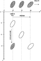
図6には、従来の方法で、移動体に映像を投光した場合の例が示されている。横軸が、投光対象物の位置を示し、縦軸が、時刻を示す。投光対象物は、楕円で示され、投光された映像は、枠無しの格子模様で示される。最上段に、理想とするプロジェクトマッチングの結果、つまり、移動する投光対象物に映像がぴたりと合った格子模様の楕円が示される。
FIG. 6 shows an example in which an image is projected onto a moving body by a conventional method. The horizontal axis indicates the position of the projection object, and the vertical axis indicates the time. The projection object is indicated by an ellipse, and the projected image is indicated by a lattice pattern without a frame. At the top, the result of the ideal project matching, that is, an ellipse with a lattice pattern in which the image fits perfectly with the moving projection object is shown.
時刻t2において、位置d2にある投光対象物の位置が検出された場合を考える。画像処理時間として、時刻t2からt4の時間を要した場合、時刻t4において、場所d2の位置に、画像処理後の映像が投光される。しかし、時刻t4には、投光対象物は位置d4まで移動しており、投光された映像は、投光対象物に投影されないことになる。
Consider a case where the position of the projection object at position d2 is detected at time t2. When the time from the time t2 to the time t4 is required as the image processing time, the video after the image processing is projected at the position d2 at the time t4. However, at time t4, the projection object has moved to the position d4, and the projected image is not projected onto the projection object.
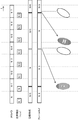
図7は、従来の方法による投光処理のタイミングチャートである。図7において、最上段「IRカメラ」は、位置検出部2のIR(赤外線)カメラ(距離画像カメラ)による位置検出処理を示し、矩形が、距離画像の検出周期を示す。2段目「位置検出」は、IRカメラが検出した距離画像から、投光対象物の位置座標(x,y,z)を算出する処理を示し、矩形が算出時間を示す。矩形内の「N」、「N+1」等は、IRカメラの検出した投光対象物Obの位置の識別子を示す(以下、「位置「N」」等というものとする。)。3段目「画像形成」は、画像処理部12が行う投光対象物の位置座標に合わせる画像処理を示し、矩形が処理時間を示す。矩形内の「N」等は、位置「N」等に応じた画像処理であることを示す。4段目「フレームBuf」は、フレームバッファに記憶されている画像を示す。矩形内の「N」等は、位置「N」に応じて画像処理がなされた映像が記憶されていることを示す。尚、ここでは、説明の便宜上、フレームバッファは1枚とする。最下段は、投光された映像、及び、投光対象物を示す。
FIG. 7 is a timing chart of the light projection processing by the conventional method. In FIG. 7, the uppermost “IR camera” indicates position detection processing by an IR (infrared) camera (distance image camera) of the position detection unit 2, and a rectangle indicates a distance image detection cycle. The second stage “position detection” indicates a process for calculating the position coordinates (x, y, z) of the projection object from the distance image detected by the IR camera, and the rectangle indicates the calculation time. “N”, “N + 1”, etc. in the rectangle indicate identifiers of the positions of the projection objects Ob detected by the IR camera (hereinafter referred to as “positions“ N ””, etc.). The third level “image formation” indicates image processing performed by the image processing unit 12 according to the position coordinates of the projection object, and the rectangle indicates the processing time. “N” or the like in the rectangle indicates image processing according to the position “N” or the like. The fourth “frame Buf” indicates an image stored in the frame buffer. “N” or the like in the rectangle indicates that an image processed according to the position “N” is stored. Here, for convenience of explanation, it is assumed that there is one frame buffer. The bottom row shows the projected image and the projection object.
図7の最下段に示すように、例えば、位置「N」における投光対象物Obに応じた映像は、投光対象物Obが位置「N+4」にいるにも関わらず、位置「N」に投光されることになる。尚、図7の最下段の図は、投光した映像が、移動した投光対象物からずれることを模式的に示している。
As shown at the bottom of FIG. 7, for example, an image corresponding to the projection object Ob at the position “N” is displayed at the position “N” even though the projection object Ob is at the position “N + 4”. It will be flooded. Note that the lowermost diagram in FIG. 7 schematically shows that the projected image is deviated from the moved projection object.
次に、図8に、投光装置100の「非同期方法」で、移動体に投光した場合の例を示す。図6に示した場合と同様に、時刻t2において、位置d2にある投光対象物の位置が検出された場合を考える。画像処理時間として、時刻t2からt4の時間を要した場合、時刻t4において、画像処理後の映像が、位置d4まで移動している投光対象物に投影される。
Next, FIG. 8 shows an example in which light is projected onto a moving body by the “asynchronous method” of the light projecting device 100. As in the case shown in FIG. 6, consider a case where the position of the projection target at position d2 is detected at time t2. When the time from time t2 to t4 is required as the image processing time, the image-processed video is projected onto the light projecting object moving to the position d4 at time t4.
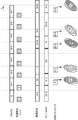
図9は、投光装置100の「非同期方法」による投光処理のタイミングチャートである。図9の、1段目から4段目のチャートは、図7における1段目から4段目のチャートと同じである。5段目の「光学トラッキング」は、光学補正を行うタイミングを示している。矩形内の「N」等は、IRカメラの検出した投光対象物Obの位置、つまり、投光部3の投光方向の変更方向を示す。最下段は、投光された映像、及び、投光対象物Obを示す。最下段の楕円は、光学補正された投光対象物Obを示し、枠無しの格子模様は、投光された映像を示し、その中の「N」等は、位置「N」の投光対象物Obに応じて画像処理された映像を示す。
FIG. 9 is a timing chart of the light projection processing by the “asynchronous method” of the light projector 100. The first to fourth charts in FIG. 9 are the same as the first to fourth charts in FIG. The fifth stage “optical tracking” indicates the timing of optical correction. “N” or the like in the rectangle indicates the position of the projection object Ob detected by the IR camera, that is, the direction in which the projection direction of the projection unit 3 is changed. The bottom row shows the projected image and the projection object Ob. The ellipse at the bottom indicates the optically corrected projection object Ob, the lattice pattern without a frame indicates the projected image, and “N” and the like therein indicate the projection target at the position “N”. The video image-processed according to the object Ob is shown.
図9に示すように、「非同期方法」において、投光装置100は、画像処理と非同期に、光学補正を行う。つまり、投光装置100は、画像処理の終了を待つことなく、IRカメラ(位置検出部2)によって位置が検出されると、すぐに光学補正を行う。また、プロジェクタのフレームバッファによる遅延時間の影響も受けない。従って、高速に移動する投光対象物Obに映像を投影することが可能となる。ただし、投光装置100は、画像処理が完了する前に、光学補正により映像を投光対象物Obに投影するため、投光対象物Obの位置に応じた完璧な映像を投影することはできないが、図9の最下段に示すように、若干前の映像を、投光対象物Obから映像を外すことなく投影することが可能となる。つまり、投光対象物Obは、光学補正によって高速でトラッキングされながら、少し遅れて画像処理により加工された映像が投光対象物Obに投影される。
As shown in FIG. 9, in the “asynchronous method”, the light projecting device 100 performs optical correction asynchronously with image processing. That is, the light projecting device 100 performs optical correction as soon as the position is detected by the IR camera (position detection unit 2) without waiting for the end of the image processing. Further, it is not affected by the delay time due to the frame buffer of the projector. Accordingly, it is possible to project an image on the projection object Ob that moves at high speed. However, since the light projecting device 100 projects an image on the light projecting object Ob by optical correction before the image processing is completed, it cannot project a perfect image corresponding to the position of the light projecting object Ob. However, as shown at the bottom of FIG. 9, it is possible to project a slightly previous image without removing the image from the projection object Ob. That is, the projected object Ob is projected on the projected object Ob with a slight delay while being tracked at high speed by optical correction.
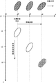
次に、図10は、投光装置100の「同期方法」で、移動体に投光した場合の例である。図6に示した場合と同様に、時刻t2において、位置d2にある投光対象物の位置が検出された場合を考える。画像処理のうち、形状変形処理の時間として、時刻t2からt3の時間を要した場合、時刻t3において、形状変形処理後の映像が、位置d3まで移動している投光対象物に投影される。そして、画像処理が時刻t4に終了すると、時刻t4において、画像処理後の映像が、位置d4まで移動している投光対象物に投影される。形状処理のみが終了した映像が、枠無しのドット模様で示され、画像処理が完了した映像が、枠無しの格子模様で示される。
Next, FIG. 10 shows an example in which light is projected onto a moving body by the “synchronization method” of the light projecting device 100. As in the case shown in FIG. 6, consider a case where the position of the projection target at position d2 is detected at time t2. In the image processing, when the time from the time t2 to the time t3 is required as the time for the shape deformation process, the image after the shape deformation process is projected onto the light projecting object moving to the position d3 at the time t3. . Then, when the image processing ends at time t4, at time t4, the image-processed video is projected onto the projection object that has moved to the position d4. An image for which only shape processing has been completed is indicated by a dot pattern without a frame, and an image for which image processing has been completed is indicated by a lattice pattern without a frame.
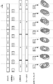
図11は、投光装置100の「同期方法」による投光処理のタイミングチャートである。図11の、1段目から5段目のチャートは、図9における1段目から5段目のチャートと同じである。尚、3段目「画像形成」の矩形のうち、「(N)」等は、位置「N」の画像処理のうちの形状処理を示し、4段目「フレームBuf」の「(N)」等は、形状処理のみが終了した映像が記憶されていることを示す。
FIG. 11 is a timing chart of the light projecting process by the “synchronization method” of the light projecting device 100. The first to fifth charts in FIG. 11 are the same as the first to fifth charts in FIG. In the third-stage “image formation” rectangle, “(N)” and the like indicate shape processing in the image processing at the position “N”, and “(N)” in the fourth-stage “frame Buf”. Etc. indicate that an image for which only shape processing has been completed is stored.
図11に示すように、投光装置100は、「同期方法」では、画像処理と同期をとって光学補正を行う。つまり、投光装置100は、画像処理のうち形状処理が終了した時点で、直近に検出された投光対象物Obの位置に投光方向を向けるように光学補正を行い、画像処理の終了した時点で、更に、直近に検出された投光対象物Obの位置に投光方向を向けるように光学補正を行う。形状処理のみであるならば比較的短時間で終了するため、投光対象物Obの移動速度が比較的低速である場合には、光学補正と形状処理との同期をとることで、投光装置100は、投光対象物Obにぴったりと合った映像を投影することが可能となる。
As shown in FIG. 11, in the “synchronization method”, the light projecting device 100 performs optical correction in synchronization with image processing. That is, the light projecting device 100 performs the optical correction so that the light projecting direction is directed to the position of the most recently detected light projecting object Ob at the time when the shape processing is completed in the image processing, and the image processing is completed. At the time, further, optical correction is performed so that the light projection direction is directed to the position of the light projection object Ob detected most recently. Since only the shape processing is completed in a relatively short time, when the moving speed of the projection object Ob is relatively low, the light projection device is obtained by synchronizing the optical correction and the shape processing. 100 can project an image that exactly matches the projection object Ob.
画像処理のみで移動体の追従処理に対応する場合、移動対象に投影する所定画像を1フレームの画像内から切り出して、位置検出部2が検出した位置に所定画像を移動させた1フレームの画像を作り出すための時間が必要であるが、投光装置100は、光学補正を行うことで、その処理が不要となる。更に、1フレームの画像内で所定画像の移動を行わせることから、所定画像の画素数は、少なくせざるを得ないが、光学補正を行う場合には、所定画像により多くの画素を割り当てることが可能となり、解像度が上がり、投光装置100は、より鮮明な画像を投影することが可能となる。
When corresponding to the tracking process of a moving object only by image processing, a predetermined image projected on a moving object is cut out from one frame image, and the predetermined image is moved to the position detected by the position detection unit 2. However, the light projecting device 100 does not need to perform this process by performing optical correction. Furthermore, since the predetermined image is moved within one frame image, the number of pixels of the predetermined image must be reduced. However, when performing optical correction, more pixels are allocated to the predetermined image. Thus, the resolution is improved, and the light projecting device 100 can project a clearer image.
尚、図11では、3段目の「画像形成」において、投光装置100は、形状処理を含む画像処理が完了してから、次の画像処理を行うこととしているが、形状処理を前の画像処理と並行して行うこととしてもよい。例えば、投光装置100は、「(N)」の処理を、「N-3」の処理と並行して行う等である。並行処理を行うための資源等が必要になるが、より短時間で画像処理を行うことができるので、投光装置100は、より高速に移動する投光対象物Obに映像を投光することが可能となる。
In FIG. 11, in the “image formation” in the third stage, the light projecting device 100 performs the next image processing after the image processing including the shape processing is completed. It may be performed in parallel with image processing. For example, the light projecting device 100 performs the process “(N)” in parallel with the process “N-3”. Although resources and the like for performing parallel processing are required, image processing can be performed in a shorter time. Therefore, the light projecting device 100 projects an image on the light projecting object Ob that moves faster. Is possible.
<動作>
実施形態の投光装置100が行う、投光処理について説明する。図12は投光処理のフローチャートである。図12の左側のフローチャートは、映像表示制御部13が行う処理であり、右側のフローチャートは、投光方向制御部14が行う処理である。 <Operation>
A light projection process performed by thelight projection device 100 according to the embodiment will be described. FIG. 12 is a flowchart of the light projection process. The flowchart on the left side of FIG. 12 is a process performed by the video display control unit 13, and the flowchart on the right side is a process performed by the light projection direction control unit 14.
実施形態の投光装置100が行う、投光処理について説明する。図12は投光処理のフローチャートである。図12の左側のフローチャートは、映像表示制御部13が行う処理であり、右側のフローチャートは、投光方向制御部14が行う処理である。 <Operation>
A light projection process performed by the
上述したように、「非同期方法」による追尾を行う場合には、映像表示制御部13と投光方向制御部14とは、それぞれ同期を取らずに単独で動作し、「同期方法」による追尾を行う場合には、同期を取って動作する。
As described above, when tracking by the “asynchronous method” is performed, the video display control unit 13 and the light projecting direction control unit 14 operate independently without synchronizing, and perform tracking by the “synchronous method”. When performing, it operates in synchronization.
まず、ユーザは、インタフェース部5を操作して、「同期方法」、又は、「非同期方法」のいずれかの追従方法を指示する。そして、ユーザは、投光処理の開始を指示するコマンドを入力する。
First, the user operates the interface unit 5 to instruct a follow-up method of either “synchronization method” or “asynchronous method”. And a user inputs the command which instruct | indicates the start of a light projection process.
インタフェース部5を介して、投光処理の開始を指示するコマンドが入力されたことを検知した投光本体部1は、まず、映像コンテンツ取得部11に対して映像コンテンツ記憶部6から映像の読み込みの開始を指示し、位置検出部2、投光部3、投光方向変更部4に対して、動作開始を指示する。また、投光本体部1は、画像処理部12、映像表示制御部13、及び、投光方向制御部14に対して、ユーザが指示した追従方法、つまり、「同期方法」、又は、「非同期方法」のいずれかを通知する。
The light projecting main body unit 1 that has detected that a command for instructing the start of the light projection process is input via the interface unit 5 first reads the video content from the video content storage unit 6 to the video content acquisition unit 11. The start of operation is instructed to the position detection unit 2, the light projecting unit 3, and the light projecting direction changing unit 4. In addition, the light projecting main body unit 1 follows the user-instructed tracking method, that is, the “synchronizing method” or “asynchronous” to the image processing unit 12, the video display control unit 13, and the light projection direction control unit 14. One of "method" is notified.
指示を受けた映像コンテンツ取得部11は、映像コンテンツ記憶部6から映像データを読み出し、画像処理部12に出力を開始する。また、位置検出部2は、投光対象物Obの位置の検出を開始し、所定の周期で検出した投光対象物Obの位置座標を、周期的に映像表示制御部13及び投光方向制御部14に出力する。
Upon receiving the instruction, the video content acquisition unit 11 reads the video data from the video content storage unit 6 and starts output to the image processing unit 12. In addition, the position detection unit 2 starts detecting the position of the projection object Ob, and periodically detects the position coordinates of the projection object Ob detected at a predetermined period, and the image display control unit 13 and the projection direction control. To the unit 14.
まず、映像表示制御部13が行う処理(左側のフローチャート)を説明する。
First, processing (left flowchart) performed by the video display control unit 13 will be described.
位置検出部2から、投光対象物Obの位置座標を入力した映像表示制御部13は(ステップS10)、入力した位置座標を画像処理部12に出力する。
The video display control unit 13 that has input the position coordinates of the projection object Ob from the position detection unit 2 (step S10) outputs the input position coordinates to the image processing unit 12.
映像コンテンツ取得部11から映像データを入力した画像処理部12は、前の画像処理が終了している場合(ステップS11:Yes)は、映像表示制御部13から入力した最新の投光対象物Obの位置座標を用いた画像処理を開始する。投光本体部1から、追従方法として「非同期方法」を通知されている場合(ステップS12:No)、画像処理部12は、映像データに対して、投光対象物Obの位置座標に応じた画像処理を行う。そして、画像処理部12は、画像処理を行った映像をフレームバッファに記憶させる(ステップS13)。
When the previous image processing has been completed (step S11: Yes), the image processing unit 12 that has input the video data from the video content acquisition unit 11 has the latest projection object Ob input from the video display control unit 13. Image processing using the position coordinates is started. When the “asynchronous method” is notified as the follow-up method from the light projecting body unit 1 (step S12: No), the image processing unit 12 responds to the position coordinates of the light projecting object Ob with respect to the video data. Perform image processing. Then, the image processing unit 12 stores the image-processed video in the frame buffer (step S13).
映像表示制御部13は、フレームバッファから映像を読み出し、所定のフレームレートで表示を行う(ステップS16)。尚、図12のフローチャートでは、説明の便宜上、ステップS16において映像の表示を行うように記載しているが、映像表示制御部13は、常に、フレームバッファから映像を読み出し、所定のフレームレートで表示を行っているものとする。
The video display control unit 13 reads the video from the frame buffer and displays it at a predetermined frame rate (step S16). In the flowchart of FIG. 12, for convenience of explanation, it is described that video is displayed in step S16. However, the video display control unit 13 always reads video from the frame buffer and displays it at a predetermined frame rate. It is assumed that
一方、ステップS12において、投光本体部1から、追従方法として「同期方法」を通知されている場合(ステップS12:Yes)、画像処理部12は、画像処理のうち、形状変形処理を映像データに行い、フレームバッファに記憶させる(ステップS14)。そして、画像処理部12は、形状変形処理が終了した旨を映像表示制御部13に通知する。通知を受けた映像表示制御部13は、投光方向制御部14に対して、同期信号を出力する。
On the other hand, when “synchronization method” is notified as the follow-up method from the light projecting main body unit 1 in step S12 (step S12: Yes), the image processing unit 12 performs the shape transformation process in the video data. And stored in the frame buffer (step S14). Then, the image processing unit 12 notifies the video display control unit 13 that the shape deformation process has been completed. Upon receiving the notification, the video display control unit 13 outputs a synchronization signal to the light projection direction control unit 14.
また、画像処理部12は、形状変形処理以外の画像処理を映像データに行い、フレームバッファに記憶させる(ステップS15)。そして、画像処理部12は、形状変形処理が終了した旨を映像表示制御部13に通知する。通知を受けた映像表示制御部13は、投光方向制御部14に対して、同期信号を出力する。
Further, the image processing unit 12 performs image processing other than the shape deformation processing on the video data and stores it in the frame buffer (step S15). Then, the image processing unit 12 notifies the video display control unit 13 that the shape deformation process has been completed. Upon receiving the notification, the video display control unit 13 outputs a synchronization signal to the light projection direction control unit 14.
映像表示制御部13は、フレームバッファから映像を読み出し、所定のフレームレートで表示を行う(ステップS16)。映像表示制御部13は、フレームバッファに形状変形処理を行った映像が記憶されている場合は、形状変形処理後の映像を表示し、フレームバッファに全ての画像処理を行った映像が記憶されている場合は、その映像を表示する。
The video display control unit 13 reads the video from the frame buffer and displays it at a predetermined frame rate (step S16). The video display control unit 13 displays the video after the shape transformation process when the video subjected to the shape transformation process is stored in the frame buffer, and the video after the whole image processing is stored in the frame buffer. If so, display the video.
次に、投光方向制御部14が行う処理(右側のフローチャート)について説明する。
Next, the process (the flowchart on the right side) performed by the light projection direction control unit 14 will be described.
位置検出部2から、投光対象物Obの位置座標を入力した投光方向制御部14は(ステップS20)、投光本体部1から、追従方法として「非同期方法」を通知されている場合(ステップS21:No)、位置検出部2から入力した投光対象物Obの位置座標に、投光部3の投光方向を向けるような指示データを、投光方向変更部4に応じて作成し、投光方向変更部4に出力する。例えば、投光方向変更部4が、図5に示すようなパンチルト雲台である場合は、パンの角度情報、及び、チルトの角度情報を算出し、投光方向変更部4に出力する。
The projection direction control unit 14 that has input the position coordinates of the projection object Ob from the position detection unit 2 (step S20) is notified of the “asynchronous method” as the follow-up method from the projection main unit 1 ( Step S21: No), in accordance with the light projection direction changing unit 4, the instruction data for directing the light projection direction of the light projecting unit 3 to the position coordinates of the light projection object Ob input from the position detection unit 2 is created. And output to the light projecting direction changing unit 4. For example, when the light projecting direction changing unit 4 is a pan / tilt head as shown in FIG. 5, pan angle information and tilt angle information are calculated and output to the light projecting direction changing unit 4.
指示を受けた投光方向変更部4は、投光方向制御部14から入力した指示データに基づいて動作し、投光部3の投光方向を変更する(ステップS23)。
Upon receiving the instruction, the light projecting direction changing unit 4 operates based on the instruction data input from the light projecting direction control unit 14, and changes the light projecting direction of the light projecting unit 3 (step S23).
一方、ステップS21において、投光本体部1から、追従方法として「同期方法」を通知されている場合(ステップS21:Yes)、投光方向制御部14は、映像表示制御部13からの同期信号が入力されるのを待ち(ステップS22:No)、同期信号が入力されると(ステップS22:Yes)、位置検出部2から入力した最新の投光対象物Obの位置座標に、投光部3の投光方向を向けるような指示データを、投光方向変更部4に応じて作成し、投光方向変更部4に出力する。指示を受けた投光方向変更部4は、投光方向制御部14から入力した指示データに基づいて動作し、投光部3の投光方向を変更する(ステップS23)。ただし、最新の位置座標がそれ以前の位置座標と所定閾値以下の差しかない場合、投光方向は維持される。
On the other hand, when “synchronization method” is notified as the follow-up method from the light projecting main body unit 1 in step S21 (step S21: Yes), the light projection direction control unit 14 receives the synchronization signal from the video display control unit 13. Is input (step S22: No), and when a synchronization signal is input (step S22: Yes), the light projecting unit is set to the position coordinates of the latest projecting object Ob input from the position detecting unit 2. 3 is generated in accordance with the light projecting direction changing unit 4 and is output to the light projecting direction changing unit 4. Upon receiving the instruction, the light projecting direction changing unit 4 operates based on the instruction data input from the light projecting direction control unit 14, and changes the light projecting direction of the light projecting unit 3 (step S23). However, if the latest position coordinates are not different from the previous position coordinates by a predetermined threshold value or less, the light projection direction is maintained.
<実施形態2>
実施形態1では、鏡胴(投光部)3の投光方向を変更する機能を持たせることで、投光装置100は、移動体の追従処理を行った。実施形態2では、鏡胴(投光部)3は、投光方向を変更する機能だけでなく、ズーム機能とフォーカス機能とを付加される。 <Embodiment 2>
In the first embodiment, thelight projecting device 100 performs the tracking process of the moving body by providing a function of changing the light projecting direction of the lens barrel (light projecting unit) 3. In the second embodiment, the lens barrel (light projecting unit) 3 is provided with not only a function of changing the light projecting direction but also a zoom function and a focus function.
実施形態1では、鏡胴(投光部)3の投光方向を変更する機能を持たせることで、投光装置100は、移動体の追従処理を行った。実施形態2では、鏡胴(投光部)3は、投光方向を変更する機能だけでなく、ズーム機能とフォーカス機能とを付加される。 <
In the first embodiment, the
投光対象物Obが、投光装置100に対して、近づいたり遠ざかったりすると、投光装置100から見て、投光対象物Obの見かけ上の大きさが変化する。図13に、投光対象物Obが投光装置100に近づいた場合の例を示す。図13に示すように、時刻t4では、時刻t2のときと比べて投光対象物Obが投光装置100に近づいているので、投光対象物Ob(楕円)は大きくなる。しかし、映像(枠無しの格子模様)は時刻t2の時の投光対象物Obの大きさであるので、投光対象物Obに対して小さく、また、ぼけた映像となる。
When the light projecting object Ob approaches or moves away from the light projecting device 100, the apparent size of the light projecting object Ob changes as viewed from the light projecting device 100. FIG. 13 shows an example when the light projecting object Ob approaches the light projecting device 100. As shown in FIG. 13, at time t4, since the light projection object Ob is closer to the light projection device 100 than at time t2, the light projection object Ob (ellipse) becomes larger. However, since the image (lattice pattern without a frame) is the size of the light projecting object Ob at the time t2, it is smaller than the light projecting object Ob and becomes a blurred image.
鏡胴(投光部)3に、ズーム機能とフォーカス機能とを付加した場合の例が、図14に示されている。時刻t4において、時刻t2の時よりも見かけ上大きくなった投光対象物Obに対し、投光対象物Obのサイズに合わせた映像が表示される。ズーム機能によって、投光光学系31が広角側に変更され、大きな映像が投光対象物Obに投影される。また、フォーカス機能により、投光対象物Obと投光装置100との距離の変化によるピントのずれが補正される。
An example in which a zoom function and a focus function are added to the lens barrel (light projecting unit) 3 is shown in FIG. At time t4, an image that matches the size of the projection object Ob is displayed for the projection object Ob that is apparently larger than that at time t2. The projection optical system 31 is changed to the wide angle side by the zoom function, and a large image is projected onto the projection object Ob. Further, the focus function corrects a focus shift due to a change in the distance between the light projecting object Ob and the light projecting device 100.
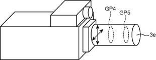
図15は、実施形態2の鏡胴(投光部)3eの例を示す図である。鏡胴(投光部)3eは、レンズ群GP4、GP5の2群の構成を備え、レンズ群GP4及びGP5を移動させることで変倍を行い、また、焦点位置を変更する。
FIG. 15 is a diagram illustrating an example of a lens barrel (light projecting unit) 3e according to the second embodiment. The lens barrel (light projecting unit) 3e has two groups of lens groups GP4 and GP5, and performs zooming by moving the lens groups GP4 and GP5, and changes the focal position.
この場合、投光方向制御部14は、投光対象物Obまでの距離に応じて、投光方向の変更に加えて、画角及び焦点距離の変更を、投光方向変更部4に指示し、投光部3が投光する映像の大きさを変更し、ピントを合わせさせることになる。
In this case, the light projecting direction control unit 14 instructs the light projecting direction changing unit 4 to change the angle of view and the focal length in addition to the change of the light projecting direction according to the distance to the light projecting object Ob. Then, the size of the image projected by the light projecting unit 3 is changed, and the focus is adjusted.
投光対象物Obと投光装置100との距離の変化に伴う映像の大きさの変更は、画像処理によっても可能である。例えば、画像処理部12が、所定の画像を切り出して、投光対象物Obの見た目上の大きさの応じたサイズに変換する。しかし、投光部3にズーム機能を持たせて、光学的にズームを行う方が、移動体の移動に対して高速に対応することができる。尚、焦点距離を合わせることは、画像処理では不可能であるので、フォーカス機能は光学的に行われる必要がある。
The change in the size of the video accompanying the change in the distance between the light projecting object Ob and the light projecting device 100 can also be performed by image processing. For example, the image processing unit 12 cuts out a predetermined image and converts it into a size corresponding to the apparent size of the projection object Ob. However, when the light projection unit 3 is provided with a zoom function and optically zooms, the moving body can be moved at high speed. Since it is impossible to adjust the focal length by image processing, the focus function needs to be performed optically.
尚、実施形態では、追従方法として、「同期方法」、「非同期方法」のいずれの方法を用いるかの選択は、ユーザがインタフェース部5を介して投光装置100に指示することとしているが、投光本体部1(切替部)は、位置検出部2が周期的に検出する投光対象物Obの位置座標に基づいて、投光対象物Obの移動速度を算出し、移動速度が所定の閾値以上である場合は「非同期方法」を用い、算出した移動速度が閾値を下回る場合は「同期方法」を用いることとしてもよい。所定の閾値は、位置検出部2の検出周期、投光部3の投光方向を変更するのに必要な時間等の、様々な条件から決定する。
In the embodiment, the user selects to use the “synchronizing method” or “asynchronous method” as the follow-up method, and the user instructs the light projecting device 100 via the interface unit 5. The light projecting body unit 1 (switching unit) calculates the moving speed of the light projecting object Ob based on the position coordinates of the light projecting object Ob periodically detected by the position detecting unit 2, and the moving speed is predetermined. The “asynchronous method” may be used when the threshold is equal to or higher than the threshold, and the “synchronous method” may be used when the calculated moving speed is lower than the threshold. The predetermined threshold is determined from various conditions such as the detection period of the position detection unit 2 and the time required to change the light projection direction of the light projection unit 3.
本明細書は、上記のように様々な態様の技術を開示しているが、そのうち主な技術を以下に纏める。
This specification discloses various modes of technology as described above, and the main technologies are summarized below.
一態様に係る投光装置は、光を投光する投光光学系を有し、投光対象物に所定形状の光を投光する投光部と、前記投光対象物の3次元位置を検出する位置検出部と、前記投光部の前記投光方向を変更する投光方向変更部と、前記投光方向変更部に前記投光方向を変更させて、前記位置検出部が検出した位置の前記投光対象物に光を投光させる投光方向制御部と、前記位置検出部が検出した位置の前記投光対象物の表面に投光する光の形状を算出する形状算出部と、前記形状算出部が算出した形状の光を、前記投光部に投光させる形状制御部とを備える。
A light projecting device according to an aspect includes a light projecting optical system that projects light, a light projecting unit that projects light of a predetermined shape onto a light projecting object, and a three-dimensional position of the light projecting object. A position detecting unit to detect, a light projecting direction changing unit for changing the light projecting direction of the light projecting unit, and a position detected by the position detecting unit by causing the light projecting direction changing unit to change the light projecting direction. A projection direction control unit that projects light onto the projection target object, a shape calculation unit that calculates the shape of light projected onto the surface of the projection target object at the position detected by the position detection unit, A shape control unit that causes the light projecting unit to project light having the shape calculated by the shape calculating unit.
他の一態様に係る投光方法は、光を投光する投光光学系を有し、投光対象物に所定形状の光を投光する投光部を備える投光装置で用いられる投光方法であって、前記投光対象物の3次元位置を検出する位置検出ステップと、前記投光部の前記投光方向を変更する投光方向変更ステップと、前記投光方向変更ステップで前記投光方向を変更させて、前記位置検出ステップで検出した位置の前記投光対象物に光を投光させる投光方向制御ステップと、前記位置検出ステップで検出した位置の前記投光対象物の表面に投光する光の形状を算出する形状算出ステップと、前記形状算出ステップで算出した形状の光を、前記投光部に投光させる形状制御ステップとを備える。
A light projecting method according to another aspect includes a light projecting optical system that projects light, and a light projecting device that includes a light projecting unit that projects light of a predetermined shape onto a light projecting target. The method includes a position detecting step of detecting a three-dimensional position of the light projecting object, a light projecting direction changing step of changing the light projecting direction of the light projecting unit, and a light projecting direction changing step. A light projection direction control step of changing the light direction to project light onto the light projection object at the position detected in the position detection step, and a surface of the light projection object at the position detected in the position detection step A shape calculating step for calculating the shape of the light to be projected onto the light source, and a shape control step for causing the light projecting unit to project the light having the shape calculated in the shape calculating step.
この構成によれば、投光装置は、投光部の投光方向を変更して、投光対象物に投光するので、投光対象物が移動した場合に、迅速に、投光対象物に投光することが可能となる。
According to this configuration, the light projecting device changes the light projecting direction of the light projecting unit and projects light onto the light projecting object. Therefore, when the light projecting object moves, the light projecting object quickly Can be projected.
上述の投光装置において、前記形状制御部が前記投光部に投光させるタイミングと非同期で、前記投光方向制御部が、前記投光方向変更部に前記投光方向を変更させる非同期モードを備える。
In the above-described light projecting device, an asynchronous mode in which the light projecting direction control unit causes the light projecting direction changing unit to change the light projecting direction is asynchronous with the timing at which the shape control unit projects light onto the light projecting unit. Prepare.
非同期モードによれば、投光対象物に投光するタイミングと同期せずに、すなわち映像処理の終了に依らずに投光部の投光方向を変更するので、投光対象物が移動した場合に、投光装置は、迅速に、投光対象物に投光することが可能となる。
According to the asynchronous mode, the light projecting direction of the light projecting unit is changed without synchronizing with the timing of projecting the light projecting object, that is, without depending on the end of the video processing. In addition, the light projecting device can quickly project the light projecting object.
また、上述の投光装置において、前記形状制御部が前記投光部に投光させるタイミングと同期して、前記投光方向制御部が、前記投光方向変更部に前記投光方向を変更させる同期モードを備え、前記形状制御部は、前記形状算出部が行う処理の一部の処理を終了したときに、当該一部の処理による光を前記投光部に投光させ、全ての処理を終了したときに、当該全ての処理による光を前記投光部に投光させる。
Moreover, in the above-described light projecting device, the light projecting direction control unit causes the light projecting direction changing unit to change the light projecting direction in synchronization with the timing at which the shape control unit projects light onto the light projecting unit. A synchronization mode, and when the shape control unit finishes a part of the process performed by the shape calculation unit, the shape control unit projects light from the part of the process to the light projecting unit, and performs all the processes. When the process is completed, the light from all the processes is projected onto the light projecting unit.
同期モードによれば、投光対象物に投光するタイミングと同期を取って、すなわち映像処理の終了に応じて投光部の投光方向を変更するので、投光対象物が低速で移動する場合には、投光装置は、形状算出部の一部の処理による光と全ての処理による光とを投光対象物に投光することが可能となる。
According to the synchronous mode, the projection object moves at a low speed because it synchronizes with the timing of projecting the projection object, that is, the projection direction of the projection unit is changed according to the end of the video processing. In this case, the light projecting device can project the light obtained by part of the processing of the shape calculating unit and the light obtained by the entire process onto the light projecting object.
上述の投光装置において、前記投光対象物の移動速度に応じて、前記同期モードと前記非同期モードとを切り替える切替部を、更に備え、前記同期モードに切り替えられた場合には、前記投光方向制御部は、前記形状制御部が前記投光部に投光させるタイミングと同期して、前記投光方向変更部に前記投光方向を変更させ、前記非同期モードに切り替えられた場合には、前記投光方向制御部は、前記形状制御部が前記投光部に投光させるタイミングと非同期で、前記位置検出部が位置を検出する毎に、前記投光方向変更部に前記投光方向を変更させる。
In the above-described light projecting device, the light projecting device further includes a switching unit that switches between the synchronous mode and the asynchronous mode according to a moving speed of the light projecting object, and when the mode is switched to the synchronous mode, When the direction control unit changes the projection direction to the projection direction change unit in synchronization with the timing at which the shape control unit projects the projection unit, and is switched to the asynchronous mode, The light projecting direction control unit is configured to set the light projecting direction to the light projecting direction changing unit every time the position detecting unit detects a position, asynchronously with the timing at which the shape control unit projects light onto the light projecting unit. Change it.
この構成によれば、投光装置は、投光対象物の移動速度に応じた適切なモードで、投光対象物に投光することが可能となる。つまり、投光対象物が高速で移動する場合は、光を外さないように、投光装置は、非同期モードで投光し、投光対象物が低速で移動する場合は、できるだけ所望する形状の光を投光対象物に投光するように、投光装置は、同期モードで投光する。
According to this configuration, the light projecting device can project the light projecting object in an appropriate mode according to the moving speed of the light projecting object. That is, when the light projecting object moves at high speed, the light projecting device projects light in the asynchronous mode so that the light is not removed. When the light projecting object moves at low speed, the light projecting object has a desired shape as much as possible. The light projecting device projects light in a synchronous mode so as to project light onto a light projecting object.
上述の投光装置において、前記位置検出部は、自装置に搭載されている。
In the above-described light projecting device, the position detection unit is mounted on the own device.
この構成によれば、投光装置に位置検出部を搭載するので、投光装置は、持ち運び等の操作性が向上し、投光部の投光方向、つまり、投光対象物の方向に、位置検出部を向けておくことが可能となる。
According to this configuration, since the position detection unit is mounted on the light projecting device, the operability such as carrying is improved, and the light projecting direction of the light projecting unit, that is, the direction of the light projecting object, The position detection unit can be directed.
上述の投光装置において、前記位置検出部は、自装置とは異なる装置に搭載されている。
In the light projecting device described above, the position detection unit is mounted on a device different from the own device.
この構成によれば、投光対象物の位置を検出しやすい場所で投光対象物の位置を検出することができるので、投光装置は、より正確な3次元の位置を検出することが可能となる。結果として、投光装置は、移動する投光対象物に追従して投光することが可能となる。
According to this configuration, since the position of the projection object can be detected at a place where the position of the projection object can be easily detected, the light projection device can detect a more accurate three-dimensional position. It becomes. As a result, the light projecting device can project light following the moving light projecting object.
上述の投光装置において、前記投光光学系は、1又は複数の光学レンズから成るレンズ群を、1又は複数有しており、前記投光方向変更部は、少なくとも1つの前記レンズ群を、前記投光光学系の光軸に対し直交する方向に移動させることで、前記投光部の前記投光方向を変更する。
In the above-described light projecting device, the light projecting optical system includes one or a plurality of lens groups including one or a plurality of optical lenses, and the light projecting direction changing unit includes at least one lens group, The projection direction of the projection unit is changed by moving the projection unit in a direction orthogonal to the optical axis of the projection optical system.
上述の投光装置において、前記投光光学系は、1又は複数のミラーを有しており、前記投光方向変更部は、前記ミラーを回転させることで、前記投光部の前記投光方向を変更する。
In the above-described light projecting device, the light projecting optical system includes one or a plurality of mirrors, and the light projecting direction changing unit rotates the mirror, thereby causing the light projecting direction of the light projecting unit to be the light projecting direction. To change.
上述の投光装置において、前記投光方向変更部は、前記投光部を、前記投光光学系の光軸に対し直交する方向に移動させることで、前記投光部の前記投光方向を変更する。
In the above-described light projecting device, the light projecting direction changing unit moves the light projecting unit in a direction orthogonal to the optical axis of the light projecting optical system, thereby changing the light projecting direction of the light projecting unit. change.
この構成によれば、投光装置は、投光部の投光方向を、容易に変更することが可能となる。
According to this configuration, the light projecting device can easily change the light projecting direction of the light projecting unit.
上述の投光装置において、前記投光部は鏡胴であり、前記投光方向変更部は、鏡胴に内蔵されている。
In the above-described light projecting device, the light projecting unit is a lens barrel, and the light projecting direction changing unit is built in the lens barrel.
この構成によれば、投光装置は、投光対象物に投光するのに適切な鏡胴に、容易に取り替えることが可能となる。
According to this configuration, the light projecting device can be easily replaced with a lens barrel that is suitable for projecting the light projecting object.
上述の投光装置において、前記投光方向変更部は、更に、前記投光部に、前記投光光学系の焦点距離を変更させるズーム機能と、前記投光部に、前記投光対象物の表面に投光された前記所定形状の光の焦点を合わせるフォーカス機能を備えている。
In the above-described light projecting device, the light projecting direction changing unit further includes a zoom function for causing the light projecting unit to change a focal length of the light projecting optical system, and a function for projecting the light projecting object to the light projecting unit. A focusing function for focusing the light of the predetermined shape projected on the surface is provided.
この構成によれば、投光対象物と投光装置との間の距離が変わった場合に、投光装置は、迅速に、移動する対象物に、対象物に応じたサイズの所定形状の光(映像)であって、ピントの合った光を投光することが可能となる。
According to this configuration, when the distance between the light projecting object and the light projecting device is changed, the light projecting device quickly transmits light of a predetermined shape having a size corresponding to the object to the moving object. It is possible to project in-focus light (video).
本発明によれば、移動する対象物に、所定形状の光(映像)を投光することができる。
According to the present invention, light (video) having a predetermined shape can be projected onto a moving object.
この出願は、2014年3月12日に出願された日本国特許出願特願2014-048823を基礎とするものであり、その内容は、本願に含まれるものである。
This application is based on Japanese Patent Application No. 2014-048823 filed on March 12, 2014, the contents of which are included in the present application.
本発明を表現するために、上述において図面を参照しながら実施形態を通して本発明を適切且つ十分に説明したが、当業者であれば上述の実施形態を変更および/または改良することは容易に為し得ることであると認識すべきである。したがって、当業者が実施する変更形態または改良形態が、請求の範囲に記載された請求項の権利範囲を離脱するレベルのものでない限り、当該変更形態または当該改良形態は、当該請求項の権利範囲に包括されると解釈される。
In order to express the present invention, the present invention has been properly and fully described through the embodiments with reference to the drawings. However, those skilled in the art can easily change and / or improve the above-described embodiments. It should be recognized that this is possible. Therefore, unless the modifications or improvements implemented by those skilled in the art are at a level that departs from the scope of the claims recited in the claims, the modifications or improvements are not covered by the claims. To be construed as inclusive.
本発明によれば、投光装置、及び、投光方法を提供することができる。
According to the present invention, it is possible to provide a light projecting device and a light projecting method.
Claims (12)
- 光を投光する投光光学系を有し、投光対象物に所定形状の光を投光する投光部と、
前記投光対象物の3次元位置を検出する位置検出部と、
前記投光部の前記投光方向を変更する投光方向変更部と、
前記投光方向変更部に前記投光方向を変更させて、前記位置検出部が検出した位置の前記投光対象物に光を投光させる投光方向制御部と、
前記位置検出部が検出した位置の前記投光対象物の表面に投光する光の形状を算出する形状算出部と、
前記形状算出部が算出した形状の光を、前記投光部に投光させる形状制御部とを備える、
投光装置。 A light projecting optical system that projects light, and a light projecting unit that projects light of a predetermined shape onto the projecting object;
A position detector for detecting a three-dimensional position of the projection object;
A light projecting direction changing unit that changes the light projecting direction of the light projecting unit;
A light projecting direction control unit that causes the light projecting direction changing unit to change the light projecting direction and projects light to the light projecting object at the position detected by the position detecting unit;
A shape calculation unit for calculating the shape of light projected on the surface of the projection object at the position detected by the position detection unit;
A shape control unit that causes the light projecting unit to project the light of the shape calculated by the shape calculating unit,
Floodlight device. - 前記形状制御部が前記投光部に投光させるタイミングと非同期で、前記投光方向制御部が、前記投光方向変更部に前記投光方向を変更させる非同期モードを備える、
請求項1に記載の投光装置。 Asynchronously with the timing at which the shape control unit causes the light projecting unit to project light, the light projecting direction control unit includes an asynchronous mode in which the light projecting direction changing unit changes the light projecting direction,
The light projecting device according to claim 1. - 前記形状制御部が前記投光部に投光させるタイミングと同期して、前記投光方向制御部が、前記投光方向変更部に前記投光方向を変更させる同期モードを備え、
前記形状制御部は、前記形状算出部が行う処理の一部の処理を終了したときに、当該一部の処理による光を前記投光部に投光させ、全ての処理を終了したときに、当該全ての処理による光を前記投光部に投光させる、
請求項1に記載の投光装置。 In synchronization with the timing when the shape control unit causes the light projecting unit to project light, the light projecting direction control unit includes a synchronization mode for causing the light projecting direction changing unit to change the light projecting direction,
When the shape control unit finishes a part of the process performed by the shape calculation unit, the light by the part process is projected to the light projecting unit, and when all the processes are finished, Projecting light from all the processes to the light projecting unit,
The light projecting device according to claim 1. - 前記投光対象物の移動速度に応じて、前記同期モードと前記非同期モードとを切り替える切替部を、更に備え、
前記同期モードに切り替えられた場合には、前記投光方向制御部は、前記形状制御部が前記投光部に投光させるタイミングと同期して、前記投光方向変更部に前記投光方向を変更させ、
前記非同期モードに切り替えられた場合には、前記投光方向制御部は、前記形状制御部が前記投光部に投光させるタイミングと非同期で、前記位置検出部が位置を検出する毎に、前記投光方向変更部に前記投光方向を変更させる、
請求項3に記載の投光装置。 A switching unit that switches between the synchronous mode and the asynchronous mode according to the moving speed of the light projecting object, further comprises:
When the mode is switched to the synchronization mode, the light projection direction control unit sets the light projection direction to the light projection direction changing unit in synchronization with the timing at which the shape control unit projects light to the light projection unit. Change
When the mode is switched to the asynchronous mode, the light projecting direction control unit is asynchronous with the timing at which the shape control unit projects light onto the light projecting unit, and each time the position detection unit detects the position, Causing the projection direction changing unit to change the projection direction;
The light projecting device according to claim 3. - 前記位置検出部は、自装置に搭載されている、
請求項1に記載の投光装置。 The position detection unit is mounted on its own device,
The light projecting device according to claim 1. - 前記位置検出部は、自装置とは異なる装置に搭載されている、
請求項1に記載の投光装置。 The position detection unit is mounted on a device different from the device itself,
The light projection device according to claim 1. - 前記投光光学系は、1又は複数の光学レンズから成るレンズ群を、1又は複数有しており、
前記投光方向変更部は、少なくとも1つの前記レンズ群を、前記投光光学系の光軸に対し直交する方向に移動させることで、前記投光部の前記投光方向を変更する、
請求項1に記載の投光装置。 The projection optical system has one or a plurality of lens groups each including one or a plurality of optical lenses,
The light projecting direction changing unit changes the light projecting direction of the light projecting unit by moving at least one lens group in a direction orthogonal to the optical axis of the light projecting optical system.
The light projecting device according to claim 1. - 前記投光光学系は、1又は複数のミラーを有しており、
前記投光方向変更部は、前記ミラーを回転させることで、前記投光部の前記投光方向を変更する、
請求項1に記載の投光装置。 The projection optical system has one or a plurality of mirrors,
The light projecting direction changing unit changes the light projecting direction of the light projecting unit by rotating the mirror.
The light projecting device according to claim 1. - 前記投光方向変更部は、前記投光部を、前記投光光学系の光軸に対し直交する方向に移動させることで、前記投光部の前記投光方向を変更する、
請求項1に記載の投光装置。 The light projecting direction changing unit changes the light projecting direction of the light projecting unit by moving the light projecting unit in a direction orthogonal to the optical axis of the light projecting optical system.
The light projecting device according to claim 1. - 前記投光部は鏡胴であり、前記投光方向変更部は、鏡胴に内蔵されている、
請求項1に記載の投光装置。 The light projecting unit is a lens barrel, and the light projecting direction changing unit is built in the lens barrel.
The light projection device according to claim 1. - 前記投光方向変更部は、更に、前記投光部に、前記投光光学系の焦点距離を変更させるズーム機能と、前記投光部に、前記投光対象物の表面に投光された前記所定形状の光の焦点を合わせるフォーカス機能を備えている、
請求項1に記載の投光装置。 The light projecting direction changing unit is further configured to cause the light projecting unit to change a focal length of the light projecting optical system, and the light projecting unit projects the surface of the light projecting object. It has a focus function to focus the light of a predetermined shape,
The light projecting device according to claim 1. - 光を投光する投光光学系を有し、投光対象物に所定形状の光を投光する投光部を備える投光装置で用いられる投光方法であって、
前記投光対象物の3次元位置を検出する位置検出ステップと、
前記投光部の前記投光方向を変更する投光方向変更ステップと、
前記投光方向変更ステップで前記投光方向を変更させて、前記位置検出ステップで検出した位置の前記投光対象物に光を投光させる投光方向制御ステップと、
前記位置検出ステップで検出した位置の前記投光対象物の表面に投光する光の形状を算出する形状算出ステップと、
前記形状算出ステップで算出した形状の光を、前記投光部に投光させる形状制御ステップとを備える、
投光方法。 A light projecting method used in a light projecting device having a light projecting optical system that projects light and having a light projecting unit that projects light of a predetermined shape onto a light projecting object,
A position detecting step for detecting a three-dimensional position of the projection object;
A light projecting direction changing step of changing the light projecting direction of the light projecting unit;
A light projecting direction control step of projecting light to the light projecting object at the position detected in the position detecting step by changing the light projecting direction in the light projecting direction changing step;
A shape calculating step for calculating the shape of light projected on the surface of the projection object at the position detected in the position detecting step;
A shape control step of causing the light projecting unit to project the light of the shape calculated in the shape calculating step,
Floodlight method.
Applications Claiming Priority (2)
| Application Number | Priority Date | Filing Date | Title |
|---|---|---|---|
| JP2014048823 | 2014-03-12 | ||
| JP2014-048823 | 2014-03-12 |
Publications (1)
| Publication Number | Publication Date |
|---|---|
| WO2015137341A1 true WO2015137341A1 (en) | 2015-09-17 |
Family
ID=54071784
Family Applications (1)
| Application Number | Title | Priority Date | Filing Date |
|---|---|---|---|
| PCT/JP2015/057018 WO2015137341A1 (en) | 2014-03-12 | 2015-03-10 | Light projection device and light projection method |
Country Status (1)
| Country | Link |
|---|---|
| WO (1) | WO2015137341A1 (en) |
Cited By (1)
| Publication number | Priority date | Publication date | Assignee | Title |
|---|---|---|---|---|
| FR3048786A1 (en) * | 2016-03-10 | 2017-09-15 | Julien Berta | DYNAMIC ADJUSTMENT OF THE SHARPNESS OF AT LEAST ONE IMAGE PROJECTED ON AN OBJECT |
Citations (4)
| Publication number | Priority date | Publication date | Assignee | Title |
|---|---|---|---|---|
| JPH0418613A (en) * | 1990-02-19 | 1992-01-22 | Dentsu Purotsukusu:Kk | Automatic tracking projector |
| JP2005189733A (en) * | 2003-12-26 | 2005-07-14 | Nikon Corp | Projector |
| JP2007312026A (en) * | 2006-05-17 | 2007-11-29 | Nippon Telegr & Teleph Corp <Ntt> | Moving body tracking photography and projection device |
| JP2009049007A (en) * | 2007-07-26 | 2009-03-05 | Panasonic Electric Works Co Ltd | Lighting device |
-
2015
- 2015-03-10 WO PCT/JP2015/057018 patent/WO2015137341A1/en active Application Filing
Patent Citations (4)
| Publication number | Priority date | Publication date | Assignee | Title |
|---|---|---|---|---|
| JPH0418613A (en) * | 1990-02-19 | 1992-01-22 | Dentsu Purotsukusu:Kk | Automatic tracking projector |
| JP2005189733A (en) * | 2003-12-26 | 2005-07-14 | Nikon Corp | Projector |
| JP2007312026A (en) * | 2006-05-17 | 2007-11-29 | Nippon Telegr & Teleph Corp <Ntt> | Moving body tracking photography and projection device |
| JP2009049007A (en) * | 2007-07-26 | 2009-03-05 | Panasonic Electric Works Co Ltd | Lighting device |
Cited By (1)
| Publication number | Priority date | Publication date | Assignee | Title |
|---|---|---|---|---|
| FR3048786A1 (en) * | 2016-03-10 | 2017-09-15 | Julien Berta | DYNAMIC ADJUSTMENT OF THE SHARPNESS OF AT LEAST ONE IMAGE PROJECTED ON AN OBJECT |
Similar Documents
| Publication | Publication Date | Title |
|---|---|---|
| US9033516B2 (en) | Determining motion of projection device | |
| US8310652B2 (en) | Image taking system and lens apparatus | |
| CN109302594B (en) | Projection display device comprising an eye tracker | |
| EP2957997B1 (en) | Image display device | |
| US20150271414A1 (en) | Display apparatus and display method | |
| JP2013246313A (en) | Camera and portable terminal apparatus | |
| US20120038592A1 (en) | Input/output device and human-machine interaction system and method thereof | |
| JP2016085379A (en) | Controller, control method, and program | |
| JP2016085380A (en) | Controller, control method, and program | |
| WO2013124901A1 (en) | Optical-projection-type display apparatus, portable terminal, and program | |
| JP2022501876A (en) | Reduced bandwidth stereo distortion compensation for fisheye lenses in head-mounted displays | |
| JP4930115B2 (en) | Image display system | |
| JP4199641B2 (en) | Projector device | |
| TWI768672B (en) | Projector focusing method and projector focusing system | |
| WO2015137341A1 (en) | Light projection device and light projection method | |
| WO2015136952A1 (en) | Gesture recognition device, head-mounted display, and portable terminal | |
| EP3547663B1 (en) | Panaoramic vision system with parallax mitigation | |
| WO2015146805A1 (en) | Light projection device and light projection method | |
| KR20130141104A (en) | An apparatus for correcting three dimensional display using sensor and a method thereof | |
| KR20050029172A (en) | Projector-camera system and focusing method for augmented reality environment | |
| JP2014115179A (en) | Measuring device, document camera and measuring method | |
| JP2006184569A (en) | Projection type display device and focusing method for the same | |
| US20130128007A1 (en) | Three-dimensional image pickup system | |
| CN105578163B (en) | Information processing method and electronic equipment | |
| JP6529160B2 (en) | AR information display device |
Legal Events
| Date | Code | Title | Description |
|---|---|---|---|
| 121 | Ep: the epo has been informed by wipo that ep was designated in this application |
Ref document number: 15760990 Country of ref document: EP Kind code of ref document: A1 |
|
| NENP | Non-entry into the national phase |
Ref country code: DE |
|
| 122 | Ep: pct application non-entry in european phase |
Ref document number: 15760990 Country of ref document: EP Kind code of ref document: A1 |
|
| NENP | Non-entry into the national phase |
Ref country code: JP |