EP3547663B1 - Panaoramic vision system with parallax mitigation - Google Patents
Panaoramic vision system with parallax mitigation Download PDFInfo
- Publication number
- EP3547663B1 EP3547663B1 EP19153163.1A EP19153163A EP3547663B1 EP 3547663 B1 EP3547663 B1 EP 3547663B1 EP 19153163 A EP19153163 A EP 19153163A EP 3547663 B1 EP3547663 B1 EP 3547663B1
- Authority
- EP
- European Patent Office
- Prior art keywords
- predetermined
- head
- image sensor
- display
- reference axis
- Prior art date
- Legal status (The legal status is an assumption and is not a legal conclusion. Google has not performed a legal analysis and makes no representation as to the accuracy of the status listed.)
- Active
Links
Images


Classifications
-
- H—ELECTRICITY
- H04—ELECTRIC COMMUNICATION TECHNIQUE
- H04N—PICTORIAL COMMUNICATION, e.g. TELEVISION
- H04N13/00—Stereoscopic video systems; Multi-view video systems; Details thereof
- H04N13/10—Processing, recording or transmission of stereoscopic or multi-view image signals
- H04N13/106—Processing image signals
- H04N13/128—Adjusting depth or disparity
-
- G—PHYSICS
- G03—PHOTOGRAPHY; CINEMATOGRAPHY; ANALOGOUS TECHNIQUES USING WAVES OTHER THAN OPTICAL WAVES; ELECTROGRAPHY; HOLOGRAPHY
- G03B—APPARATUS OR ARRANGEMENTS FOR TAKING PHOTOGRAPHS OR FOR PROJECTING OR VIEWING THEM; APPARATUS OR ARRANGEMENTS EMPLOYING ANALOGOUS TECHNIQUES USING WAVES OTHER THAN OPTICAL WAVES; ACCESSORIES THEREFOR
- G03B37/00—Panoramic or wide-screen photography; Photographing extended surfaces, e.g. for surveying; Photographing internal surfaces, e.g. of pipe
- G03B37/04—Panoramic or wide-screen photography; Photographing extended surfaces, e.g. for surveying; Photographing internal surfaces, e.g. of pipe with cameras or projectors providing touching or overlapping fields of view
-
- G—PHYSICS
- G02—OPTICS
- G02B—OPTICAL ELEMENTS, SYSTEMS OR APPARATUS
- G02B27/00—Optical systems or apparatus not provided for by any of the groups G02B1/00 - G02B26/00, G02B30/00
- G02B27/01—Head-up displays
- G02B27/017—Head mounted
-
- H—ELECTRICITY
- H04—ELECTRIC COMMUNICATION TECHNIQUE
- H04N—PICTORIAL COMMUNICATION, e.g. TELEVISION
- H04N13/00—Stereoscopic video systems; Multi-view video systems; Details thereof
- H04N13/20—Image signal generators
- H04N13/282—Image signal generators for generating image signals corresponding to three or more geometrical viewpoints, e.g. multi-view systems
-
- H—ELECTRICITY
- H04—ELECTRIC COMMUNICATION TECHNIQUE
- H04N—PICTORIAL COMMUNICATION, e.g. TELEVISION
- H04N13/00—Stereoscopic video systems; Multi-view video systems; Details thereof
- H04N13/30—Image reproducers
- H04N13/332—Displays for viewing with the aid of special glasses or head-mounted displays [HMD]
-
- H—ELECTRICITY
- H04—ELECTRIC COMMUNICATION TECHNIQUE
- H04N—PICTORIAL COMMUNICATION, e.g. TELEVISION
- H04N13/00—Stereoscopic video systems; Multi-view video systems; Details thereof
- H04N13/30—Image reproducers
- H04N13/366—Image reproducers using viewer tracking
- H04N13/371—Image reproducers using viewer tracking for tracking viewers with different interocular distances; for tracking rotational head movements around the vertical axis
-
- H—ELECTRICITY
- H04—ELECTRIC COMMUNICATION TECHNIQUE
- H04N—PICTORIAL COMMUNICATION, e.g. TELEVISION
- H04N13/00—Stereoscopic video systems; Multi-view video systems; Details thereof
- H04N13/30—Image reproducers
- H04N13/366—Image reproducers using viewer tracking
- H04N13/38—Image reproducers using viewer tracking for tracking vertical translational head movements
-
- H—ELECTRICITY
- H04—ELECTRIC COMMUNICATION TECHNIQUE
- H04N—PICTORIAL COMMUNICATION, e.g. TELEVISION
- H04N13/00—Stereoscopic video systems; Multi-view video systems; Details thereof
- H04N13/30—Image reproducers
- H04N13/398—Synchronisation thereof; Control thereof
-
- H—ELECTRICITY
- H04—ELECTRIC COMMUNICATION TECHNIQUE
- H04N—PICTORIAL COMMUNICATION, e.g. TELEVISION
- H04N23/00—Cameras or camera modules comprising electronic image sensors; Control thereof
- H04N23/60—Control of cameras or camera modules
- H04N23/698—Control of cameras or camera modules for achieving an enlarged field of view, e.g. panoramic image capture
-
- H—ELECTRICITY
- H04—ELECTRIC COMMUNICATION TECHNIQUE
- H04N—PICTORIAL COMMUNICATION, e.g. TELEVISION
- H04N23/00—Cameras or camera modules comprising electronic image sensors; Control thereof
- H04N23/90—Arrangement of cameras or camera modules, e.g. multiple cameras in TV studios or sports stadiums
-
- H—ELECTRICITY
- H04—ELECTRIC COMMUNICATION TECHNIQUE
- H04N—PICTORIAL COMMUNICATION, e.g. TELEVISION
- H04N2213/00—Details of stereoscopic systems
- H04N2213/001—Constructional or mechanical details
Definitions
- the present invention generally relates to panoramic vision systems, and more particularly relates to a panoramic vision system with parallax mitigation.
- a camera ring allows for a panoramic view with much less "fish-eye” distortion and higher resolution than a single camera.
- the individual cameras With a camera ring, the individual cameras each produce images that overlap, and the overlapping images are then stitched together to produce a single, expanded FOV image.
- the most accurate technique is to generate depth fields and then apply the video images captured by the cameras as textures overlaying the depth fields. Although this technique is fairly accurate, the processing time associated with generating the depth fields results in excessive latency for real-time applications, such as driving a vehicle with indirect vision.
- a technique is also used to transition between the cameras.
- One relatively simple technique is to simply switch between cameras at about the center of the angle between the two cameras. This has the advantage of low latency, but causes a rather pronounced "jump" in the scene due to parallax difference.
- WO2017168347A1 discloses a method, where a first and second stereoscopic image are formed comprising a left eye image and a right eye image, a first central image region and a first peripheral image region are determined in the first stereoscopic image, the first central image region comprising a first central scene feature and the first peripheral image region comprising a first peripheral scene feature, and in the second stereoscopic image a second central image region and a second peripheral image region in said second stereoscopic image are determined, and based on said determining that said second central image region comprises said first peripheral scene feature, encoding said first stereoscopic image such that said first peripheral image region is encoded with a reduced quality with respect to said first central image region.
- EP3065406A1 discloses a video streaming method, comprising receiving a panoramic video; receiving head-tracking data; determining a current field of view based on the head-tracking data.
- the resolution of the panoramic video may be adjusted based on the current field of view, wherein resolution of the current field of view is a first resolution and the resolution outside of the current field of view is a second resolution.
- the panoramic video with adjusted resolution may be provided, wherein the first resolution is higher than the second resolution.
- EP2631728A2 discloses a method and apparatus for transmitting sensory data over a bidirectional data link to reproduce an audiovisual environment for a physically displaced operator.
- the apparatus includes a stationary or mobile surveillance platform equipped with transducers for capturing local sensory information including audio, visual, haptic, thermal, and other metrics associated with human perception.
- the sensory data is processed, transmitted over the data link, and displayed to the operator to simulate a virtual presence.
- the system further includes ergonomic sensors for detecting head, body, limb, and/or eye related operator motion to allow the operator to remotely manipulate the sensory transducers to selectively configure the field of perception within the measured environment.
- EP3177010A1 discloses that first, an image rendering processor corrects the user's head posture angle using the camera posture angle and clips a display angle of view depending on the corrected user's head posture angle from the captured image to render a free viewpoint image. Then, an image processing device transmits the free viewpoint image rendered by the image rendering processor to a display device via a communication unit, and the image is displayed on the display device.
- a panoramic image system with parallax mitigation includes a plurality of image sensors, a head tracker, a display, and a processor.
- Each image sensor is fixedly mounted a predetermined linear distance from a first reference axis and is disposed adjacent to at least one other image sensor.
- Each image sensor is disposed to point in a direction that is offset from its adjacent image sensor by a predetermined angle.
- the head tracker is configured to sense at least the angular position and the movement direction of a viewer's head about a second reference axis and to supply an azimuth position signal representative thereof, where the second reference axis is parallel to the first reference axis.
- the display is configured to selectively display images sensed by each of the image sensors.
- the processor is in operable communication with each of the image sensors, with the head tracker, and with the display.
- the processor is configured, based at least on the azimuth position signal, to command the display to display images sensed by only one of the image sensors.
- a panoramic image system with parallax mitigation includes a first image sensor, a second image sensor, a third image sensor, a head tracker, a near-to-eye display, and a processor.
- the first image sensor is fixedly mounted a predetermined linear distance from a first reference axis and is disposed to point in a first direction.
- the second image sensor is fixedly mounted the predetermined linear distance from the first reference axis and is disposed to point in a second direction, where the second direction is a predetermined angular magnitude in a first rotational direction about the reference axis.
- the third image sensor is fixedly mounted the predetermined linear distance from the first reference axis and is disposed to point in a third direction, where the third direction is the predetermined angular magnitude in a second rotational direction about the reference axis.
- the head tracker is configured to sense at least the angular position and the movement direction of a viewer's head about a second reference axis and to supply an azimuth position signal representative thereof, where the second reference axis is parallel to the first reference axis.
- the near-to-eye display is configured to selectively display images sensed by each of the image sensors.
- the processor is in operable communication with each of the image sensors, with the head tracker, and with the near-to-eye display.
- the processor is configured, based at least on the azimuth position signal, to command the near-to-eye display to display images sensed by only one of the image sensors.
- a panoramic image system with parallax mitigation includes a first image sensor, a second image sensor, a third image sensor, a head tracker, a near-to-eye display, and a processor.
- the first image sensor is fixedly mounted a predetermined linear distance from a first reference axis and is disposed to point in a first direction.
- the second image sensor is fixedly mounted the predetermined linear distance from the first reference axis and is disposed to point in a second direction, where the second direction is a predetermined angular magnitude in a first rotational direction about the reference axis.
- the third image sensor is fixedly mounted the predetermined linear distance from the first reference axis and is disposed to point in a third direction, where the third direction is the predetermined angular magnitude in a second rotational direction about the reference axis.
- the head tracker is configured to sense at least the angular position and the movement direction of a viewer's head about a second reference axis and to supply an azimuth position signal representative thereof, where the second reference axis is parallel to the first reference axis.
- the near-to-eye display is configured to selectively display images sensed by each of the image sensors.
- the processor is in operable communication with each of the image sensors, with the head tracker, and with the near-to-eye display.
- the processor is configured, based at least on the azimuth position signal, to command the near-to-eye display to: (i) display images sensed by only the first image sensor at least when the angular position of the viewer's head, relative to the first direction, is between a first predetermined snap angle and a second predetermined snap angle, wherein the first and second predetermined snap angles are less than the predetermined angular magnitude, (ii) display images sensed by only the second image sensor at least when the angular position of the viewer's head is greater than the first predetermined snap angle, and (iii) display images sensed by only the third image sensor at least when the angular position of the viewer's head is greater than the second predetermined snap angle.
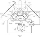
- a panoramic image system 100 with parallax mitigation includes at least a plurality of image sensors 102 (102-1, 102-2, 102-3 ... 102-N), a head tracker 104, a display 106, and a processor 108.
- Each image sensor 102 is fixedly mounted a predetermined linear distance from a first reference axis 110, and is disposed adjacent to at least one other image sensor 102.
- each image sensor 102 is fixedly mounted to a camera ring mount structure 114 that, at least in the depicted embodiment, is semi-circular in cross-section. It will be appreciated that in other embodiments, the camera ring mount structure 114 could be less than semi-circular in cross-section, circular in cross-section, or between semi-circular and circular in cross-section.
- each image sensor 102 is disposed to point in a direction that is offset from its adjacent image sensor 102 by a predetermined angular magnitude ( ⁇ ).
- ⁇ the predetermined angular magnitude
- the system 100 is implemented with three image sensors 102 - a first image sensor 102-1, a second image sensor 102-2, and a third image sensor 102-3.
- the first image sensor 102-1 is fixedly mounted a predetermined linear distance (di) from a first reference axis 110 and is disposed to point in a first direction 112.
- the second image sensor 102-2 and the third image sensor 102-3 are also fixedly mounted the predetermined linear distance from the first reference axis 110.
- the second image sensor 102-2 is disposed to point in a second direction 114 and the third image sensor 102-3 is disposed to point in a third direction 116.
- the second direction is the predetermined angular magnitude ( ⁇ ) in a first rotational direction 118 about the reference axis 110
- the third direction is the predetermined angular magnitude ( ⁇ ) in a second rotational direction 120 about the reference axis 110.
- the predetermined angular magnitude ( ⁇ ) is 45-degrees.
- each image sensor 102 may be variously configured and implemented.
- each image sensor 102 may be implemented using one, two, or three or more image sensing devices.
- each of the image sensors 102 comprise a pair of stereoscopic cameras 122 - a first camera 122-1 and a second camera 122-2.
- the first and second cameras in each pair 122 are identical, and have identically dimensioned, and partially overlapping, sensor field-of-views (FOVs).
- each first camera 122-1 has a first FOV 124-1
- each second camera 122-2 has a second FOV 124-2 that is equal to the first FOV 124-1.
- the first and second FOVs 124-1, 124-2 each have a horizontal FOV (HFOV) of 76-degrees and a vertical FOV (VFOV) of 61-degrees.
- HFOV horizontal FOV
- VFOV vertical FOV
- the horizontal and vertical FOVs can vary.
- the stereoscopic camera pairs 122 that comprise each image sensor 102 are separated by a predetermined separation distance (d), the first and second FOVs 124-1, 124-2 are not fully coextensive.
- the predetermined separation distance (d) may vary. In one particular embodiment, however, the predetermined separation distance (d) is about 2.5-inches (or 63.5 mm), which corresponds to around the mean interpupillary distance (IPD) for human males. It will be appreciated that the predetermined separation distance (d) may vary, and may, in some embodiments, be adjustable to a longer or shorter separation distance.
- the head tracker 104 is configured to sense at least the angular position and movement direction of a viewer's head 126 about a second reference axis 128 that is parallel to the first reference axis 110.
- the head tracker 104 is configured, in response to movement about the second reference axis 128, to supply an azimuth position signal representative thereof to the processor 108.
- the head tracker 104 may also be further configured, in at least some embodiments, to sense the angular position and movement direction of the viewer's head 126 about a third reference axis 132 that is perpendicular to both the first and second reference axes 110, 128.
- the head tracker 104 when configured to do so, is further configured, in response to movement about the third reference axis 132, to supply an elevation position signal representative thereof to the processor 108.
- the head tracker 104 may be implemented using any one of numerous known sensing devices for sensing the azimuthal and/or elevational position of a viewer's head 126. Some non-limiting examples include inertial measurement units (IMUs), magnetic head trackers, optical head trackers, and various combinations thereof.
- IMUs inertial measurement units
- magnetic head trackers magnetic head trackers
- optical head trackers and various combinations thereof.
- the display 106 is configured to selectively display images sensed by each of the image sensors 102. More specifically, and as will be described further below, the display is responsive to commands from the processor 108 to display images from only one of the image sensors 102.
- the display 106 may be implemented using any one of numerous known display types, such as a near-to-eye (NTE) display or a forward looking display that scans around a plurality of images using conventional controls. In one particular embodiment, the display 106 is implemented using a NTE display, such as a head-worn device that is configured similar to a pair of goggles or glasses.
- the display 106 also has a FOV. Although the FOV of the display 106 may vary, it is typically smaller and narrower than the FOV of the cameras 122.
- the first and second sensor FOVs 124-1, 124-2 each have a horizontal FOV (HFOV) of 76-degrees and a vertical FOV (VFOV) of 61-degrees
- this same implementation uses a NTE display 106 that has a HFOV of 20-degees and a VFOV of 27-degrees.
- the NTE display 106 implements a portrait type FOV. It will be appreciated that in other embodiments the cameras and NTE display 106 could both implement landscape or portrait type FOVs.
- the processor 108 is in operable communication with each of the image sensors 102, with the head tracker 104, and with the NTE display 106.
- the processor 108 receives at least the azimuth position signal from the head tracker 104, and is configured, based at least on the azimuth position signal, to command the NTE display 106 to display images sensed by only one of the image sensors 102.
- the processor 108 in response to at least on the azimuth position signal, commands the NTE display 106 to display images sensed by only the first image sensor 102-1, by only the second image sensor 102-2, or by only the third image sensor 102-3, based on the rotational angle/azimuthal position of the viewer's head relative to the first direction 112. That rotational angle is referred to herein as the nominal snap angle ( ⁇ nom ).
- the snap angle ( ⁇ nom ) is the angle at which the scene, displayed in the display 106, snaps from one sensor 102 (e.g., camera pair) to the next adjacent sensor (e.g., camera pair).
- the snap angle ( ⁇ nom ) occurs in the overlap region of adjacent sensor FOVs to provide a seamless imagery to the display 106 as the head is panned.
- the snap minimizes parallax errors associated with displaying images, simultaneously, from two different angles, and includes a predetermined amount of hysteresis.
- the system 100 is preferably implemented to include four predetermined snap angles - a first predetermined snap angle ( ⁇ 1 ), a second predetermined snap angle ( ⁇ 2 ), a third predetermined snap angle ( ⁇ 3 ), and a fourth predetermined snap angle ( ⁇ 4 ).
- the first predetermined snap angle ( ⁇ 1 ) is a rotational angle/azimuthal position of the viewer's head 126, relative to the first direction 112, in the first rotational direction 118.
- the second predetermined snap angle ( ⁇ 2 ) is a rotational angle/azimuthal position of the viewer's head 126, relative to the first direction 112, in the second rotational direction 120.
- the third predetermined snap angle ( ⁇ 3 ) is a rotational angle/azimuthal position of the viewer's head 126, relative to the first direction 112, in the first rotational direction 118.
- the fourth predetermined snap angle ( ⁇ 4 ) is a rotational angle/azimuthal position of the viewer's head 126, relative to the first direction 112, in the second rotational direction 120.
- the processor 108 is configured to command the NTE display 106 to display images sensed by only the first image sensor 102-1 at least when the rotational position of the viewer's head 126, relative to the first direction 112, is between the first predetermined snap angle ( ⁇ 1 ) and the second predetermined snap angle ( ⁇ 2 ).
- the processor 108 is additionally configured to command the NTE display 106 to display images sensed by only the second image sensor 102-2 at least when the angular position of the viewer's head 126 is greater than the first predetermined snap angle ( ⁇ 1 ), and to display images sensed by only the third image sensor 102-3 at least when the angular position of the viewer's head 126 is greater than the second predetermined snap angle ( ⁇ 2 ) in the second rotational direction 124.
- the processor 108 is configured to command the NTE display 106 to stop displaying images sensed by the second image sensor 102-2 and begin displaying images sensed by only the first image sensor 102-1 only after the angular position of the viewer's head 126 reaches the third predetermined snap angle ( ⁇ 3 ).
- the processor 108 is configured to command the NTE display 106 to stop displaying images sensed by the third image sensor 102-3 and begin displaying images sensed by the first image sensor 102-1 only after the angular position of the viewer's head 126 reaches the fourth predetermined snap angle ( ⁇ 4 ).
- each of the cameras 122 that comprise the image sensors 102 has a horizontal FOV (HFOV) of 76-degrees and a vertical FOV (VFOV) of 61-degrees.
- the predetermined angular magnitude ( ⁇ ) is 45-degrees, which results in a total HFOV of 166 degrees (90+76).
- the nominal snap angle ( ⁇ nom ) is +/-22.5-degrees, with +/-2-degrees of hysteresis.
- the first predetermined snap angle ( ⁇ 1 ) is 24.5 degrees in the first rotational direction 118
- the second predetermined snap angle ( ⁇ 2 ) is 24.5 degrees in the second rotational direction 120
- the third predetermined snap angle ( ⁇ 3 ) is 20.5 degrees in the first rotational direction 118
- the fourth predetermined snap angle ( ⁇ 4 ) is 20.5 degrees in the second rotational direction 120.
- the head tracker 104 is further configured to sense the angular position and movement direction of the viewer's head 126 about the third reference axis 132.
- the position about the third reference axis 132 is referred to as the elevation angle of the viewer's head 126, and is used to adjust the predetermined snap angles ( ⁇ ).
- the predetermined snap angles ( ⁇ ) can be optimized based on the distance to the object being viewed. However, the distance to various objects at a given azimuth angle may not (indeed, likely will not) be known.
- the approach implemented herein is to optimize the predetermined snap angles ( ⁇ ) at the horizon for 0-degree elevation, and at about 15 feet for -20-degree elevation (e.g., when looking down).
- the processor 108 then linearly interpolates between the two azimuth offsets between 0- and -20-degrees.
- the head tracker 104 is further configured to sense the angular position and movement direction of the viewer's head 126 about the third reference axis 132.
- the position about the third reference axis 132 is referred to as the elevation angle of the viewer's head 126, and is used to adjust the predetermined snap angles ( ⁇ ) with an offset angle. This offset is then applied to the target snap angle to which the processor is transitioning.
- the predetermined snap angle ( ⁇ ) offset can be optimized based on the distance to the object being viewed at the current elevation angle. However, the distance to various objects at a given azimuth angle may not (indeed, likely will not) be known.
- the approach implemented herein is to optimize the predetermined snap angles ( ⁇ ) offset at the horizon for 0-degree elevation, and at about 15 feet for -20-degree elevation (e.g., when looking down and where the distance at -20-degree elevation is based on the height of the sensors 102).
- the processor 108 then linearly interpolates between the two azimuth offsets between 0 and -20-degrees.
- the snap angle offsets are clamped at the two extremes (0-degree and -20-degree elevation).
- the elevation is effectively used as a first approximation to the distance.
- the snap will occur at 24.5-degrees, and the right sensor centroid rotation is set to -41.9-degrees instead of -45-degrees (3.1-degrees azimuth offset, which means the camera image rotates left by that angle or the head moved to the right by that amount).
- the right sensor centroid rotates by 46.2-degrees (-1.2 azimuth offset).
- the processor 108 configured to adjust the first, second, third, and fourth predetermined snap angles based on the elevation position signal, it is also configured, in a least some embodiments, to linearly reduce the adjustments to the first, second, third, and fourth predetermined snap angles based additionally on the azimuth position signal. This is because, even though the snaps between image sensors 102 at the predetermined snap angles was quite clean, there was an offset in the images supplied from the second and third image sensors 102-2, 102-3. It has been found that this offset can be mitigated by linearly bleeding off the offset such that it is dissipated at the center azimuth angle of each of the image sensors 102.
- bleed off may be dissipated at an arbitrary angle between the center azimuth and the snap angle, and not just the center azimuth, as in the described embodiment.
- FIG. 3 a more detailed description of the operation of the system 100 will be provided.
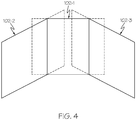
- the FOVs 124 of the first 102-1, second 102-2, and third 102-3 image sensors are depicted in FIG. 3 in two-dimensions, rather than in three-dimensions.
- a representation of the FOVs 124 of the first 102-1, second 102-2, and third 102-3 image sensors in three-dimensions is depicted, in simplified form, in FIG. 4 .
- the processor 108 commands the NTE display 106 to display images sensed by only the first image sensor 102-1 (i.e., only images within the FOV 124 of the first image sensor 102-1), and such image corresponds to an initial display FOV 302 within the FOV 124 of the first image sensor 102-1.
- the initial display FOV 302, and all other display FOVs described hereafter correspond to the display FOV of the NTE display 106.
- the processor 108 commands the NTE display 106 to display images sensed by only the second image sensor 102-2 (i.e., only images within the FOV 124 of the second image sensor 102-2), as represented by display FOV 306.
- the NTE display 106 will continue displaying images sensed by only the second image sensor 102-2.
- the processor 108 commands the NTE display 106 to switch to displaying images sensed by only the first image sensor 102-1 (i.e., only images within the FOV 124 of the second image sensor 102-1), as represented by display FOV 310.
- the NTE display 106 will continue displaying images sensed by only the first image sensor 102-1.
- the processor 108 commands the NTE display 106 to display images sensed by only the first image sensor 102-1. This again corresponds to the initial display FOV 302 within the FOV 124 of the first image sensor 102-1.
- the processor 108 commands the NTE display 106 to display images sensed by only the third image sensor 102-3 (i.e., only images within the FOV 124 of the third image sensor 102-3), as represented by display FOV 314.
- the NTE display 106 will continue displaying images sensed by only the third image sensor 102-3.
- the processor 108 commands the NTE display 106 to switch to displaying images sensed by only the first image sensor 102-1 (i.e., only images within the FOV 124 of the first image sensor 102-1), as represented by display FOV 318.
- the NTE display 106 will continue displaying images sensed by only the first image sensor 102-1.
- Two additional display FOVs 320, 322 are depicted in FIG. 3 and, for completeness, the functionality of the system 100 associated with these display FOVs will now be described. Specifically, one display FOV 320 is depicted approaching the lower-left boundary of the FOV of the second image sensor 102-2, and the other display FOV 322 is depicted approaching the upper-right boundary of the FOV of the third image sensor 102-3. If the azimuthal and/or elevation position of the viewer's head 126 moves beyond the boundaries of the image sensor FOVs 124, the size of the display FOVs 320, 322 (i.e., the FOV of the NTE display 106) is cropped (typically replaced with black).
- the system and method described herein provide a relatively dramatic improvement in parallax error mitigation.
- the system described herein was placed in a window-less vehicle and field tested on a desert course. During the field testing, none of the operators complained about optical discontinuity of the scene as the images transitioned between image sensors (i.e., camera pairs). It is noted that that if the distance to the object is different than the optimized distance, there may be a noticeable jump between two image sensors. That, however, has proven to be a minor issue to the operators.
- Skilled artisans may implement the described functionality in varying ways for each particular application, but such implementation decisions should not be interpreted as causing a departure from the scope of the present invention.
- an embodiment of a system or a component may employ various integrated circuit components, e.g., memory elements, digital signal processing elements, logic elements, look-up tables, or the like, which may carry out a variety of functions under the control of one or more microprocessors or other control devices.
- integrated circuit components e.g., memory elements, digital signal processing elements, logic elements, look-up tables, or the like, which may carry out a variety of functions under the control of one or more microprocessors or other control devices.
- DSP digital signal processor
- ASIC application specific integrated circuit
- FPGA field programmable gate array
- a general-purpose processor may be a microprocessor, but in the alternative, the processor may be any conventional processor, controller, microcontroller, or state machine.
- a processor may also be implemented as a combination of computing devices, e.g., a combination of a DSP and a microprocessor, a plurality of microprocessors, one or more microprocessors in conjunction with a DSP core, or any other such configuration.
- a software module may reside in RAM memory, flash memory, ROM memory, EPROM memory, EEPROM memory, registers, hard disk, a removable disk, a CD-ROM, or any other form of storage medium known in the art.
- An exemplary storage medium is coupled to the processor such that the processor can read information from, and write information to, the storage medium.
- the storage medium may be integral to the processor.
- the processor and the storage medium may reside in an ASIC.
- an embodiment of a system or a component may employ various integrated circuit components, e.g., memory elements, digital signal processing elements, logic elements, look-up tables, or the like, which may carry out a variety of functions under the control of one or more microprocessors or other control devices.
- integrated circuit components e.g., memory elements, digital signal processing elements, logic elements, look-up tables, or the like, which may carry out a variety of functions under the control of one or more microprocessors or other control devices.
- various elements of the systems described herein are essentially the code segments or instructions that perform the various tasks.
- the program or code segments can be stored in a processor-readable medium or transmitted by a computer data signal embodied in a carrier wave over a transmission medium or communication path.
- the "computer-readable medium”, “processor-readable medium”, or “machine-readable medium” may include any medium that can store or transfer information. Examples of the processor-readable medium include an electronic circuit, a semiconductor memory device, a ROM, a flash memory, an erasable ROM (EROM), a floppy diskette, a CD-ROM, an optical disk, a hard disk, a fiber optic medium, a radio frequency (RF) link, or the like.
- RF radio frequency
- the computer data signal may include any signal that can propagate over a transmission medium such as electronic network channels, optical fibers, air, electromagnetic paths, or RF links.
- the code segments may be downloaded via computer networks such as the Internet, an intranet, a LAN, or the like.
- modules Some of the functional units described in this specification have been referred to as "modules" in order to more particularly emphasize their implementation independence.
- functionality referred to herein as a module may be implemented wholly, or partially, as a hardware circuit comprising custom VLSI circuits or gate arrays, off-the-shelf semiconductors such as logic chips, transistors, or other discrete components.
- a module may also be implemented in programmable hardware devices such as field programmable gate arrays, programmable array logic, programmable logic devices, or the like. Modules may also be implemented in software for execution by various types of processors.
- An identified module of executable code may, for instance, comprise one or more physical or logical modules of computer instructions that may, for instance, be organized as an object, procedure, or function.
- the executables of an identified module need not be physically located together, but may comprise disparate instructions stored in different locations that, when joined logically together, comprise the module and achieve the stated purpose for the module.
- a module of executable code may be a single instruction, or many instructions, and may even be distributed over several different code segments, among different programs, and across several memory devices.
- operational data may be embodied in any suitable form and organized within any suitable type of data structure. The operational data may be collected as a single data set, or may be distributed over different locations including over different storage devices, and may exist, at least partially, merely as electronic signals on a system or network.
Description
- The present invention generally relates to panoramic vision systems, and more particularly relates to a panoramic vision system with parallax mitigation.
- Various techniques are known for extending the field of view (FOV) of a camera. One technique is to mount a plurality of cameras on circular or semi-circular mount structure to implement what is sometimes referred to as a camera ring. A camera ring allows for a panoramic view with much less "fish-eye" distortion and higher resolution than a single camera. With a camera ring, the individual cameras each produce images that overlap, and the overlapping images are then stitched together to produce a single, expanded FOV image.
- Various techniques are also used to implement the image stitching. The most accurate technique is to generate depth fields and then apply the video images captured by the cameras as textures overlaying the depth fields. Although this technique is fairly accurate, the processing time associated with generating the depth fields results in excessive latency for real-time applications, such as driving a vehicle with indirect vision.
- As may be appreciated, when implementing a camera ring, a technique is also used to transition between the cameras. One relatively simple technique is to simply switch between cameras at about the center of the angle between the two cameras. This has the advantage of low latency, but causes a rather pronounced "jump" in the scene due to parallax difference.
- Hence, there is a need for a system and method for transitioning between cameras on a camera ring that eliminates, or at least significantly mitigates, parallax differences, and that does not rely on processing techniques that exhibit relatively excessive latency. The present invention addresses at least these needs.
-
WO2017168347A1 discloses a method, where a first and second stereoscopic image are formed comprising a left eye image and a right eye image, a first central image region and a first peripheral image region are determined in the first stereoscopic image, the first central image region comprising a first central scene feature and the first peripheral image region comprising a first peripheral scene feature, and in the second stereoscopic image a second central image region and a second peripheral image region in said second stereoscopic image are determined, and based on said determining that said second central image region comprises said first peripheral scene feature, encoding said first stereoscopic image such that said first peripheral image region is encoded with a reduced quality with respect to said first central image region. -
EP3065406A1 discloses a video streaming method, comprising receiving a panoramic video; receiving head-tracking data; determining a current field of view based on the head-tracking data. The resolution of the panoramic video may be adjusted based on the current field of view, wherein resolution of the current field of view is a first resolution and the resolution outside of the current field of view is a second resolution. The panoramic video with adjusted resolution may be provided, wherein the first resolution is higher than the second resolution. -
EP2631728A2 discloses a method and apparatus for transmitting sensory data over a bidirectional data link to reproduce an audiovisual environment for a physically displaced operator. The apparatus includes a stationary or mobile surveillance platform equipped with transducers for capturing local sensory information including audio, visual, haptic, thermal, and other metrics associated with human perception. The sensory data is processed, transmitted over the data link, and displayed to the operator to simulate a virtual presence. The system further includes ergonomic sensors for detecting head, body, limb, and/or eye related operator motion to allow the operator to remotely manipulate the sensory transducers to selectively configure the field of perception within the measured environment. -
EP3177010A1 discloses that first, an image rendering processor corrects the user's head posture angle using the camera posture angle and clips a display angle of view depending on the corrected user's head posture angle from the captured image to render a free viewpoint image. Then, an image processing device transmits the free viewpoint image rendered by the image rendering processor to a display device via a communication unit, and the image is displayed on the display device. - The present invention in its various aspects is as set out in the appended claims. This summary is provided to describe select concepts in a simplified form that are further described in the Detailed Description. This summary is not intended to identify key or essential features of the claimed subject matter, nor is it intended to be used as an aid in determining the scope of the claimed subject matter.
- In one embodiment, a panoramic image system with parallax mitigation includes a plurality of image sensors, a head tracker, a display, and a processor. Each image sensor is fixedly mounted a predetermined linear distance from a first reference axis and is disposed adjacent to at least one other image sensor. Each image sensor is disposed to point in a direction that is offset from its adjacent image sensor by a predetermined angle. The head tracker is configured to sense at least the angular position and the movement direction of a viewer's head about a second reference axis and to supply an azimuth position signal representative thereof, where the second reference axis is parallel to the first reference axis. The display is configured to selectively display images sensed by each of the image sensors. The processor is in operable communication with each of the image sensors, with the head tracker, and with the display. The processor is configured, based at least on the azimuth position signal, to command the display to display images sensed by only one of the image sensors.
- In another embodiment, a panoramic image system with parallax mitigation includes a first image sensor, a second image sensor, a third image sensor, a head tracker, a near-to-eye display, and a processor. The first image sensor is fixedly mounted a predetermined linear distance from a first reference axis and is disposed to point in a first direction. The second image sensor is fixedly mounted the predetermined linear distance from the first reference axis and is disposed to point in a second direction, where the second direction is a predetermined angular magnitude in a first rotational direction about the reference axis. The third image sensor is fixedly mounted the predetermined linear distance from the first reference axis and is disposed to point in a third direction, where the third direction is the predetermined angular magnitude in a second rotational direction about the reference axis. The head tracker is configured to sense at least the angular position and the movement direction of a viewer's head about a second reference axis and to supply an azimuth position signal representative thereof, where the second reference axis is parallel to the first reference axis. The near-to-eye display is configured to selectively display images sensed by each of the image sensors. The processor is in operable communication with each of the image sensors, with the head tracker, and with the near-to-eye display. The processor is configured, based at least on the azimuth position signal, to command the near-to-eye display to display images sensed by only one of the image sensors.
- In yet another embodiment, a panoramic image system with parallax mitigation includes a first image sensor, a second image sensor, a third image sensor, a head tracker, a near-to-eye display, and a processor. The first image sensor is fixedly mounted a predetermined linear distance from a first reference axis and is disposed to point in a first direction. The second image sensor is fixedly mounted the predetermined linear distance from the first reference axis and is disposed to point in a second direction, where the second direction is a predetermined angular magnitude in a first rotational direction about the reference axis. The third image sensor is fixedly mounted the predetermined linear distance from the first reference axis and is disposed to point in a third direction, where the third direction is the predetermined angular magnitude in a second rotational direction about the reference axis. The head tracker is configured to sense at least the angular position and the movement direction of a viewer's head about a second reference axis and to supply an azimuth position signal representative thereof, where the second reference axis is parallel to the first reference axis. The near-to-eye display is configured to selectively display images sensed by each of the image sensors. The processor is in operable communication with each of the image sensors, with the head tracker, and with the near-to-eye display. The processor is configured, based at least on the azimuth position signal, to command the near-to-eye display to: (i) display images sensed by only the first image sensor at least when the angular position of the viewer's head, relative to the first direction, is between a first predetermined snap angle and a second predetermined snap angle, wherein the first and second predetermined snap angles are less than the predetermined angular magnitude, (ii) display images sensed by only the second image sensor at least when the angular position of the viewer's head is greater than the first predetermined snap angle, and (iii) display images sensed by only the third image sensor at least when the angular position of the viewer's head is greater than the second predetermined snap angle.
- Furthermore, other desirable features and characteristics of the panoramic image system and method will become apparent from the subsequent detailed description and the appended claims, taken in conjunction with the accompanying drawings and the preceding background.
- The present invention will hereinafter be described in conjunction with the following drawing figures, wherein like numerals denote like elements, and wherein:
-
FIG. 1 depicts a functional block diagram of a panoramic image system with parallax mitigation; -
FIG. 2 depicts a simplified representation of a viewer's head and various snap angles that are implemented in the system ofFIG. 1 ; -
FIG. 3 depicts the field-of-views (FOVs) of a plurality of image sensors in two dimensions; and -
FIG. 4 depicts the field-of-views (FOVs) of the plurality of image sensors in three dimensions. - The following detailed description is merely exemplary in nature and is not intended to limit the invention or the application and uses of the invention. As used herein, the word "exemplary" means "serving as an example, instance, or illustration." Thus, any embodiment described herein as "exemplary" is not necessarily to be construed as preferred or advantageous over other embodiments. All of the embodiments described herein are exemplary embodiments provided to enable persons skilled in the art to make or use the invention and not to limit the scope of the invention which is defined by the claims. Furthermore, there is no intention to be bound by any expressed or implied theory presented in the preceding technical field, background, brief summary, or the following detailed description.
- Referring to
FIG. 1 , apanoramic image system 100 with parallax mitigation is depicted and includes at least a plurality of image sensors 102 (102-1, 102-2, 102-3 ... 102-N), ahead tracker 104, adisplay 106, and aprocessor 108. Each image sensor 102 is fixedly mounted a predetermined linear distance from afirst reference axis 110, and is disposed adjacent to at least one other image sensor 102. In the depicted embodiment, each image sensor 102 is fixedly mounted to a camera ring mount structure 114 that, at least in the depicted embodiment, is semi-circular in cross-section. It will be appreciated that in other embodiments, the camera ring mount structure 114 could be less than semi-circular in cross-section, circular in cross-section, or between semi-circular and circular in cross-section. - Regardless of the specific cross-section shape of the camera ring mount structure 114, each image sensor 102 is disposed to point in a direction that is offset from its adjacent image sensor 102 by a predetermined angular magnitude (α). It will be appreciated that the predetermined angular magnitude (α) may vary, and may be determined based, for example, on the number of image sensors 102 included in the
system 100. In the depicted embodiment, thesystem 100 is implemented with three image sensors 102 - a first image sensor 102-1, a second image sensor 102-2, and a third image sensor 102-3. - The first image sensor 102-1 is fixedly mounted a predetermined linear distance (di) from a
first reference axis 110 and is disposed to point in afirst direction 112. The second image sensor 102-2 and the third image sensor 102-3 are also fixedly mounted the predetermined linear distance from thefirst reference axis 110. However, the second image sensor 102-2 is disposed to point in a second direction 114 and the third image sensor 102-3 is disposed to point in athird direction 116. AsFIG. 1 illustrates, the second direction is the predetermined angular magnitude (α) in a firstrotational direction 118 about thereference axis 110, and the third direction is the predetermined angular magnitude (α) in a secondrotational direction 120 about thereference axis 110. In one particular embodiment, the predetermined angular magnitude (α) is 45-degrees. - It will additionally be appreciated that the image sensors 102 may be variously configured and implemented. For example, each image sensor 102 may be implemented using one, two, or three or more image sensing devices. In the depicted embodiment, each of the image sensors 102 comprise a pair of stereoscopic cameras 122 - a first camera 122-1 and a second camera 122-2. Preferably, the first and second cameras in each
pair 122 are identical, and have identically dimensioned, and partially overlapping, sensor field-of-views (FOVs). For example, each first camera 122-1 has a first FOV 124-1, and each second camera 122-2 has a second FOV 124-2 that is equal to the first FOV 124-1. Although the FOV of each camera may vary, in one particular physical implementation, the first and second FOVs 124-1, 124-2 each have a horizontal FOV (HFOV) of 76-degrees and a vertical FOV (VFOV) of 61-degrees. As may be appreciated, the horizontal and vertical FOVs can vary. - As may be appreciated, because the stereoscopic camera pairs 122 that comprise each image sensor 102 are separated by a predetermined separation distance (d), the first and second FOVs 124-1, 124-2 are not fully coextensive. The predetermined separation distance (d) may vary. In one particular embodiment, however, the predetermined separation distance (d) is about 2.5-inches (or 63.5 mm), which corresponds to around the mean interpupillary distance (IPD) for human males. It will be appreciated that the predetermined separation distance (d) may vary, and may, in some embodiments, be adjustable to a longer or shorter separation distance.
- The
head tracker 104 is configured to sense at least the angular position and movement direction of a viewer'shead 126 about asecond reference axis 128 that is parallel to thefirst reference axis 110. Thehead tracker 104 is configured, in response to movement about thesecond reference axis 128, to supply an azimuth position signal representative thereof to theprocessor 108. Thehead tracker 104 may also be further configured, in at least some embodiments, to sense the angular position and movement direction of the viewer'shead 126 about athird reference axis 132 that is perpendicular to both the first and second reference axes 110, 128. Thehead tracker 104, when configured to do so, is further configured, in response to movement about thethird reference axis 132, to supply an elevation position signal representative thereof to theprocessor 108. Thehead tracker 104 may be implemented using any one of numerous known sensing devices for sensing the azimuthal and/or elevational position of a viewer'shead 126. Some non-limiting examples include inertial measurement units (IMUs), magnetic head trackers, optical head trackers, and various combinations thereof. - The
display 106 is configured to selectively display images sensed by each of the image sensors 102. More specifically, and as will be described further below, the display is responsive to commands from theprocessor 108 to display images from only one of the image sensors 102. Thedisplay 106 may be implemented using any one of numerous known display types, such as a near-to-eye (NTE) display or a forward looking display that scans around a plurality of images using conventional controls. In one particular embodiment, thedisplay 106 is implemented using a NTE display, such as a head-worn device that is configured similar to a pair of goggles or glasses. Thedisplay 106 also has a FOV. Although the FOV of thedisplay 106 may vary, it is typically smaller and narrower than the FOV of thecameras 122. For example, in the embodiment in which the first and second sensor FOVs 124-1, 124-2 each have a horizontal FOV (HFOV) of 76-degrees and a vertical FOV (VFOV) of 61-degrees, this same implementation uses aNTE display 106 that has a HFOV of 20-degees and a VFOV of 27-degrees. Thus, in this embodiment, while the cameras implement landscape type FOVs, theNTE display 106 implements a portrait type FOV. It will be appreciated that in other embodiments the cameras andNTE display 106 could both implement landscape or portrait type FOVs. - The
processor 108 is in operable communication with each of the image sensors 102, with thehead tracker 104, and with theNTE display 106. Theprocessor 108, as noted above, receives at least the azimuth position signal from thehead tracker 104, and is configured, based at least on the azimuth position signal, to command theNTE display 106 to display images sensed by only one of the image sensors 102. More specifically, when, as in the depicted embodiment, thesystem 100 is implemented with three image sensors 102-1, 102-2, 102-3, theprocessor 108, in response to at least on the azimuth position signal, commands theNTE display 106 to display images sensed by only the first image sensor 102-1, by only the second image sensor 102-2, or by only the third image sensor 102-3, based on the rotational angle/azimuthal position of the viewer's head relative to thefirst direction 112. That rotational angle is referred to herein as the nominal snap angle (βnom). - The snap angle (βnom) is the angle at which the scene, displayed in the
display 106, snaps from one sensor 102 (e.g., camera pair) to the next adjacent sensor (e.g., camera pair). The snap angle (βnom) occurs in the overlap region of adjacent sensor FOVs to provide a seamless imagery to thedisplay 106 as the head is panned. The snap minimizes parallax errors associated with displaying images, simultaneously, from two different angles, and includes a predetermined amount of hysteresis. Thus, as will now be described, thesystem 100 is preferably implemented to include four predetermined snap angles - a first predetermined snap angle (β1), a second predetermined snap angle (β2), a third predetermined snap angle (β3), and a fourth predetermined snap angle (β4). - Referring to
FIG. 2 , the first predetermined snap angle (β1) is a rotational angle/azimuthal position of the viewer'shead 126, relative to thefirst direction 112, in the firstrotational direction 118. The second predetermined snap angle (β2) is a rotational angle/azimuthal position of the viewer'shead 126, relative to thefirst direction 112, in the secondrotational direction 120. The third predetermined snap angle (β3) is a rotational angle/azimuthal position of the viewer'shead 126, relative to thefirst direction 112, in the firstrotational direction 118. The fourth predetermined snap angle (β4) is a rotational angle/azimuthal position of the viewer'shead 126, relative to thefirst direction 112, in the secondrotational direction 120. - In view of the foregoing description, the
processor 108 is configured to command theNTE display 106 to display images sensed by only the first image sensor 102-1 at least when the rotational position of the viewer'shead 126, relative to thefirst direction 112, is between the first predetermined snap angle (β1) and the second predetermined snap angle (β2). Theprocessor 108 is additionally configured to command theNTE display 106 to display images sensed by only the second image sensor 102-2 at least when the angular position of the viewer'shead 126 is greater than the first predetermined snap angle (β1), and to display images sensed by only the third image sensor 102-3 at least when the angular position of the viewer'shead 126 is greater than the second predetermined snap angle (β2) in the second rotational direction 124. - Because, as noted, the
system 100 is implemented to include hysteresis, when the angular position of the viewer'shead 126 is greater than the first predetermined snap angle (β1) and the viewer'shead 126 is rotating in the secondrotational direction 120, theprocessor 108 is configured to command theNTE display 106 to stop displaying images sensed by the second image sensor 102-2 and begin displaying images sensed by only the first image sensor 102-1 only after the angular position of the viewer'shead 126 reaches the third predetermined snap angle (β3). Similarly, when the angular position of the viewer'shead 126 is greater than the second predetermined snap angle (β2) and the viewer'shead 126 is rotating in the firstrotational direction 118, theprocessor 108 is configured to command theNTE display 106 to stop displaying images sensed by the third image sensor 102-3 and begin displaying images sensed by the first image sensor 102-1 only after the angular position of the viewer'shead 126 reaches the fourth predetermined snap angle (β4). - It will be appreciated that the relative magnitudes of the first, second, third, and fourth predetermined snap angles may vary. In one particular embodiment, however, the first and second predetermined snap angles (β1, β2) are equal in magnitude to each other, and are greater in magnitude than the nominal snap angle (βnom). The third and fourth predetermined snap angles (β3=β4) are equal in magnitude to each other, and are less in magnitude than nominal snap angle (βnom). Additionally, the first and second predetermined snap angles (β1, β2) are each greater in magnitude than the third and fourth predetermined magnitudes (β3, β4). It should additionally be noted that the first and second predetermined snap angles (β1, β2) are each less than the predetermined angular magnitude (α).
- As mentioned above, in one particular physical implementation, each of the
cameras 122 that comprise the image sensors 102 has a horizontal FOV (HFOV) of 76-degrees and a vertical FOV (VFOV) of 61-degrees. Moreover, as was also noted above, the predetermined angular magnitude (α) is 45-degrees, which results in a total HFOV of 166 degrees (90+76). With this configuration, the nominal snap angle (βnom) is +/-22.5-degrees, with +/-2-degrees of hysteresis. Thus, the first predetermined snap angle (β1) is 24.5 degrees in the firstrotational direction 118, the second predetermined snap angle (β2) is 24.5 degrees in the secondrotational direction 120, the third predetermined snap angle (β3) is 20.5 degrees in the firstrotational direction 118, and the fourth predetermined snap angle (β4) is 20.5 degrees in the secondrotational direction 120. - As was noted above, in some embodiments the
head tracker 104 is further configured to sense the angular position and movement direction of the viewer'shead 126 about thethird reference axis 132. The position about thethird reference axis 132 is referred to as the elevation angle of the viewer'shead 126, and is used to adjust the predetermined snap angles (β). Ideally, the predetermined snap angles (β) can be optimized based on the distance to the object being viewed. However, the distance to various objects at a given azimuth angle may not (indeed, likely will not) be known. Thus, the approach implemented herein is to optimize the predetermined snap angles (β) at the horizon for 0-degree elevation, and at about 15 feet for -20-degree elevation (e.g., when looking down). Theprocessor 108 then linearly interpolates between the two azimuth offsets between 0- and -20-degrees. - As was noted above, in some embodiments the
head tracker 104 is further configured to sense the angular position and movement direction of the viewer'shead 126 about thethird reference axis 132. The position about thethird reference axis 132 is referred to as the elevation angle of the viewer'shead 126, and is used to adjust the predetermined snap angles (β) with an offset angle. This offset is then applied to the target snap angle to which the processor is transitioning. Ideally, the predetermined snap angle (β) offset can be optimized based on the distance to the object being viewed at the current elevation angle. However, the distance to various objects at a given azimuth angle may not (indeed, likely will not) be known. Thus, the approach implemented herein is to optimize the predetermined snap angles (β) offset at the horizon for 0-degree elevation, and at about 15 feet for -20-degree elevation (e.g., when looking down and where the distance at -20-degree elevation is based on the height of the sensors 102). Theprocessor 108 then linearly interpolates between the two azimuth offsets between 0 and -20-degrees. The snap angle offsets are clamped at the two extremes (0-degree and -20-degree elevation). In this embodiment, the elevation is effectively used as a first approximation to the distance. - As a non-limiting example, given 0-degrees elevation, an azimuth transition at 24.5-degrees, and a center-to-right transition, the snap will occur at 24.5-degrees, and the right sensor centroid rotation is set to -41.9-degrees instead of -45-degrees (3.1-degrees azimuth offset, which means the camera image rotates left by that angle or the head moved to the right by that amount). For the same transition at -20-degrees of elevation, the right sensor centroid rotates by 46.2-degrees (-1.2 azimuth offset). When moving from the right camera to the center camera at 0-degrees of elevation, if the snap occurs at 20.5 degrees, then the right sensor centroid rotation is changed from 0-degrees to -3.1-degrees (sensor image moves to the right or head to the left). At -20-degrees of elevation, the rotation of the center sensor is 1.2-degrees.
- Not only is the
processor 108 configured to adjust the first, second, third, and fourth predetermined snap angles based on the elevation position signal, it is also configured, in a least some embodiments, to linearly reduce the adjustments to the first, second, third, and fourth predetermined snap angles based additionally on the azimuth position signal. This is because, even though the snaps between image sensors 102 at the predetermined snap angles was quite clean, there was an offset in the images supplied from the second and third image sensors 102-2, 102-3. It has been found that this offset can be mitigated by linearly bleeding off the offset such that it is dissipated at the center azimuth angle of each of the image sensors 102. If the viewer'shead 126 is rotated azimuthally back toward the associated predetermined snap angle without going to the bleed off limit, then the residual angle is adjusted out in the snap back to the other image sensor 102. It will be appreciated that bleed off may be dissipated at an arbitrary angle between the center azimuth and the snap angle, and not just the center azimuth, as in the described embodiment. - Turning now to
FIG. 3 , a more detailed description of the operation of thesystem 100 will be provided. In doing so, it is noted that, for ease of illustration and description, the FOVs 124 of the first 102-1, second 102-2, and third 102-3 image sensors are depicted inFIG. 3 in two-dimensions, rather than in three-dimensions. For completeness, a representation of the FOVs 124 of the first 102-1, second 102-2, and third 102-3 image sensors in three-dimensions is depicted, in simplified form, inFIG. 4 . - Returning now to
FIG. 3 , it is assumed that the azimuthal position of the viewer'shead 126 is initially positioned between the first and second predetermined snap angles (β1, β 2). Thus, theprocessor 108 commands theNTE display 106 to display images sensed by only the first image sensor 102-1 (i.e., only images within the FOV 124 of the first image sensor 102-1), and such image corresponds to aninitial display FOV 302 within the FOV 124 of the first image sensor 102-1. Before proceeding further, it is noted that theinitial display FOV 302, and all other display FOVs described hereafter, correspond to the display FOV of theNTE display 106. - With the above initial conditions in mind, if the viewer rotates their
head 126 from the initial position (i.e., between the first and second predetermined snap angles (β1, β2) in the firstrotational direction 118, and continues to do so, when the azimuthal position of viewer's head reaches the first predetermined snap angle (β1), as represented bydisplay FOV 304, theprocessor 108 commands theNTE display 106 to display images sensed by only the second image sensor 102-2 (i.e., only images within the FOV 124 of the second image sensor 102-2), as represented bydisplay FOV 306. As long as the azimuthal position of the user'shead 126 is greater than the first predetermined snap angle (β1), theNTE display 106 will continue displaying images sensed by only the second image sensor 102-2. - If, as depicted in phantom in
FIG. 3 , the viewer thereafter rotates theirhead 126 in the secondrotational direction 120, and continues to do so, when the azimuthal position of viewer'shead 126 reaches the third predetermined snap angle (β3), as represented bydisplay FOV 308, theprocessor 108 commands theNTE display 106 to switch to displaying images sensed by only the first image sensor 102-1 (i.e., only images within the FOV 124 of the second image sensor 102-1), as represented bydisplay FOV 310. Again, as long as the azimuthal position of the user'shead 126 is between the first and second predetermined snap angles (β1, β2), theNTE display 106 will continue displaying images sensed by only the first image sensor 102-1. - Now, it is assumed again that the azimuthal position of the viewer's
head 126 is positioned between the first and second predetermined snap angles (β1, β2), which means theprocessor 108 commands theNTE display 106 to display images sensed by only the first image sensor 102-1. This again corresponds to theinitial display FOV 302 within the FOV 124 of the first image sensor 102-1. If the viewer rotates theirhead 126 in the secondrotational direction 120, and continues to do so, when the azimuthal position of viewer'shead 126 reaches the second predetermined snap angle (β2), as represented bydisplay FOV 312, theprocessor 108 commands theNTE display 106 to display images sensed by only the third image sensor 102-3 (i.e., only images within the FOV 124 of the third image sensor 102-3), as represented bydisplay FOV 314. As long as the azimuthal position of the user'shead 126 is greater than the second predetermined snap angle (β2), theNTE display 106 will continue displaying images sensed by only the third image sensor 102-3. - If, as once again depicted in phantom in
FIG. 3 , the viewer thereafter rotates theirhead 126 in the firstrotational direction 118, and continues to do so, when the azimuthal position of viewer'shead 126 reaches the fourth predetermined snap angle (β4), as represented bydisplay FOV 316, theprocessor 108 commands theNTE display 106 to switch to displaying images sensed by only the first image sensor 102-1 (i.e., only images within the FOV 124 of the first image sensor 102-1), as represented bydisplay FOV 318. Again, as long as the azimuthal position of the user'shead 126 is between the first and second predetermined snap angles (β1, β2), theNTE display 106 will continue displaying images sensed by only the first image sensor 102-1. - Two
additional display FOVs FIG. 3 and, for completeness, the functionality of thesystem 100 associated with these display FOVs will now be described. Specifically, onedisplay FOV 320 is depicted approaching the lower-left boundary of the FOV of the second image sensor 102-2, and theother display FOV 322 is depicted approaching the upper-right boundary of the FOV of the third image sensor 102-3. If the azimuthal and/or elevation position of the viewer'shead 126 moves beyond the boundaries of the image sensor FOVs 124, the size of thedisplay FOVs 320, 322 (i.e., the FOV of the NTE display 106) is cropped (typically replaced with black). - The system and method described herein provide a relatively dramatic improvement in parallax error mitigation. The system described herein was placed in a window-less vehicle and field tested on a desert course. During the field testing, none of the operators complained about optical discontinuity of the scene as the images transitioned between image sensors (i.e., camera pairs). It is noted that that if the distance to the object is different than the optimized distance, there may be a noticeable jump between two image sensors. That, however, has proven to be a minor issue to the operators.
- Those of skill in the art will appreciate that the various illustrative logical blocks, modules, circuits, and algorithm steps described in connection with the embodiments disclosed herein may be implemented as electronic hardware, computer software, or combinations of both. Some of the embodiments and implementations are described above in terms of functional and/or logical block components (or modules) and various processing steps. However, it should be appreciated that such block components (or modules) may be realized by any number of hardware, software, and/or firmware components configured to perform the specified functions. To clearly illustrate this interchangeability of hardware and software, various illustrative components, blocks, modules, circuits, and steps have been described above generally in terms of their functionality. Whether such functionality is implemented as hardware or software depends upon the particular application and design constraints imposed on the overall system. Skilled artisans may implement the described functionality in varying ways for each particular application, but such implementation decisions should not be interpreted as causing a departure from the scope of the present invention. For example, an embodiment of a system or a component may employ various integrated circuit components, e.g., memory elements, digital signal processing elements, logic elements, look-up tables, or the like, which may carry out a variety of functions under the control of one or more microprocessors or other control devices. In addition, those skilled in the art will appreciate that embodiments described herein are merely exemplary implementations.
- The various illustrative logical blocks, modules, and circuits described in connection with the embodiments disclosed herein may be implemented or performed with a general-purpose processor, a digital signal processor (DSP), an application specific integrated circuit (ASIC), a field programmable gate array (FPGA) or other programmable logic device, discrete gate or transistor logic, discrete hardware components, or any combination thereof designed to perform the functions described herein. A general-purpose processor may be a microprocessor, but in the alternative, the processor may be any conventional processor, controller, microcontroller, or state machine. A processor may also be implemented as a combination of computing devices, e.g., a combination of a DSP and a microprocessor, a plurality of microprocessors, one or more microprocessors in conjunction with a DSP core, or any other such configuration.
- The steps of a method or algorithm described in connection with the embodiments disclosed herein may be embodied directly in hardware, in a software module executed by a processor, or in a combination of the two. A software module may reside in RAM memory, flash memory, ROM memory, EPROM memory, EEPROM memory, registers, hard disk, a removable disk, a CD-ROM, or any other form of storage medium known in the art. An exemplary storage medium is coupled to the processor such that the processor can read information from, and write information to, the storage medium. In the alternative, the storage medium may be integral to the processor. The processor and the storage medium may reside in an ASIC.
- Techniques and technologies may be described herein in terms of functional and/or logical block components, and with reference to symbolic representations of operations, processing tasks, and functions that may be performed by various computing components or devices. Such operations, tasks, and functions are sometimes referred to as being computer-executed, computerized, software-implemented, or computer-implemented. In practice, one or more processor devices can carry out the described operations, tasks, and functions by manipulating electrical signals representing data bits at memory locations in the system memory, as well as other processing of signals. The memory locations where data bits are maintained are physical locations that have particular electrical, magnetic, optical, or organic properties corresponding to the data bits. It should be appreciated that the various block components shown in the figures may be realized by any number of hardware, software, and/or firmware components configured to perform the specified functions. For example, an embodiment of a system or a component may employ various integrated circuit components, e.g., memory elements, digital signal processing elements, logic elements, look-up tables, or the like, which may carry out a variety of functions under the control of one or more microprocessors or other control devices.
- When implemented in software or firmware, various elements of the systems described herein are essentially the code segments or instructions that perform the various tasks. The program or code segments can be stored in a processor-readable medium or transmitted by a computer data signal embodied in a carrier wave over a transmission medium or communication path. The "computer-readable medium", "processor-readable medium", or "machine-readable medium" may include any medium that can store or transfer information. Examples of the processor-readable medium include an electronic circuit, a semiconductor memory device, a ROM, a flash memory, an erasable ROM (EROM), a floppy diskette, a CD-ROM, an optical disk, a hard disk, a fiber optic medium, a radio frequency (RF) link, or the like. The computer data signal may include any signal that can propagate over a transmission medium such as electronic network channels, optical fibers, air, electromagnetic paths, or RF links. The code segments may be downloaded via computer networks such as the Internet, an intranet, a LAN, or the like.
- Some of the functional units described in this specification have been referred to as "modules" in order to more particularly emphasize their implementation independence. For example, functionality referred to herein as a module may be implemented wholly, or partially, as a hardware circuit comprising custom VLSI circuits or gate arrays, off-the-shelf semiconductors such as logic chips, transistors, or other discrete components. A module may also be implemented in programmable hardware devices such as field programmable gate arrays, programmable array logic, programmable logic devices, or the like. Modules may also be implemented in software for execution by various types of processors. An identified module of executable code may, for instance, comprise one or more physical or logical modules of computer instructions that may, for instance, be organized as an object, procedure, or function. Nevertheless, the executables of an identified module need not be physically located together, but may comprise disparate instructions stored in different locations that, when joined logically together, comprise the module and achieve the stated purpose for the module. Indeed, a module of executable code may be a single instruction, or many instructions, and may even be distributed over several different code segments, among different programs, and across several memory devices. Similarly, operational data may be embodied in any suitable form and organized within any suitable type of data structure. The operational data may be collected as a single data set, or may be distributed over different locations including over different storage devices, and may exist, at least partially, merely as electronic signals on a system or network.
- In this document, relational terms such as first and second, and the like may be used solely to distinguish one entity or action from another entity or action without necessarily requiring or implying any actual such relationship or order between such entities or actions. Numerical ordinals such as "first," "second," "third," etc. simply denote different singles of a plurality and do not imply any order or sequence unless specifically defined by the claim language. The sequence of the text in any of the claims does not imply that process steps must be performed in a temporal or logical order according to such sequence unless it is specifically defined by the language of the claim. The process steps may be interchanged in any order without departing from the scope of the invention as long as such an interchange does not contradict the claim language and is not logically nonsensical.
- Furthermore, depending on the context, words such as "connect" or "coupled to" used in describing a relationship between different elements do not imply that a direct physical connection must be made between these elements. For example, two elements may be connected to each other physically, electronically, logically, or in any other manner, through one or more additional elements.
- While at least one exemplary embodiment has been presented in the foregoing detailed description of the invention, it should be appreciated that a vast number of variations exist. It should also be appreciated that the exemplary embodiment or exemplary embodiments are only examples, and are not intended to limit the scope, applicability, or configuration of the invention in any way. Rather, the foregoing detailed description will provide those skilled in the art with a convenient road map for implementing an exemplary embodiment of the invention. It being understood that various changes may be made in the function and arrangement of elements described in an exemplary embodiment without departing from the scope of the invention as set forth in the appended claims.
Claims (6)
- A panoramic image system (100) with parallax mitigation, the system comprising:a plurality of image sensors (102), each image sensor (102-1, 102-2, 102-3... 102-N) fixedly mounted a predetermined linear distance from a first reference axis and disposed adjacent to at least one other image sensor, each image sensor disposed to point in a direction that is offset from its adjacent image sensor by a predetermined angle;a head tracker (104) configured to sense at least angular position and movement direction of a viewer's head about a second reference axis (128) and to supply an azimuth position signal representative thereof, the second reference axis (128) parallel to the first reference axis (110);a display (106) configured to selectively display images sensed by each of the image sensors (102); anda processor (108) in operable communication with each of the image sensors (102), with the head tracker (104), and with the display (106), the processor (108) configured, based at least on the azimuth position signal, to command the display (106) to display images sensed by only one of the image sensors (102), wherein the plurality of image sensors (100) comprises:a first image sensor (102-1) fixedly mounted a predetermined linear distance from a first reference axis (110) and disposed to point in a first direction (112);a second image sensor (102-2) fixedly mounted the predetermined linear distance from the first reference axis (110) and disposed to point in a second direction (114), the second direction (114) being a predetermined angular magnitude in a first rotational direction (118) about the first reference axis (110); anda third image sensor (102-3) fixedly mounted the predetermined linear distance from the first reference axis (110) and disposed to point in a third direction (116), the third direction (116) being the predetermined angular magnitude in a second rotational direction (120) about the first reference axis (110);wherein the processor (108) is further configured to command the display (106) to:display images sensed by only the first image sensor (102-1) at least when the angular position of the viewer's head, relative to the first direction (112), is between a first predetermined snap angle and a second predetermined snap angle;display images sensed by only the second image sensor (102-2) at least when the angular position of the viewer's head is greater than the first predetermined snap angle; anddisplay images sensed by only the third image sensor (102-3) at least when the angular position of the viewer's head is greater than the second predetermined snap angle,wherein the first and second predetermined snap angles are less than the predetermined angular magnitude between the image sensors;wherein:when the angular position of the viewer's head is greater than the first predetermined snap angle and the viewer's head is rotating in the second rotational direction (120), the processor (108) commands the display (106) to stop displaying images sensed by the second image sensor(102-2) and begin displaying images sensed by the first image sensor (102-1) when the angular position of the viewer's head is at a third predetermined snap angle; andwhen the angular position of the viewer's head is greater than the second predetermined snap angle and the viewer's head is rotating in the first rotational direction (118), the processor (108) commands the display (100) to stop displaying images sensed by the third image sensor (102-3) and begin displaying images sensed by the first image sensor (102-1) when the angular position of the viewer's head is at a fourth predetermined snap angle;wherein the first and third predetermined snap angles are predetermined angular magnitudes in the first rotational direction (118) about the second reference axis (128) and the second and fourth predetermined snap angles are predetermined angular magnitudes in the second rotational direction (120) about the second reference axis (128);characterized in that;the head tracker (104) is further configured to sense angular position and movement direction of the viewer's head about a third reference axis (132) and supply elevation position signals representative thereof, the third reference axis (132) perpendicular to the first reference axis (110) and the second reference axis (128); andthe processor is further configured to adjust the first, second, third, and fourth predetermined snap angles based on the elevation position signal.
- The system (100) of claim 1, wherein:each of the image sensors (102) comprises one or more cameras; andthe display is configured as a near-to-eye display.
- The system (100) of claim 1, wherein the first predetermined snap angle is equal in magnitude to the second predetermined snap angle.
- The system (100) of claim 1, wherein:the third predetermined snap angle and the fourth predetermined snap angle are both less than the first predetermined snap angle; andthe third predetermined snap angle is equal in magnitude to the fourth predetermined snap angle.
- The system (100) of claim 1, wherein:the third predetermined snap angle and the fourth predetermined snap angle are both less than the first predetermined snap angle; andthe second predetermined snap angle and the third predetermined snap angle are unequal in magnitude.
- The system (100) of claim 1, wherein the processor (108) is further configured to reduce the adjustments to the first, second, third, and fourth predetermined snap angles based additionally on the elevation position signal.
Applications Claiming Priority (1)
| Application Number | Priority Date | Filing Date | Title |
|---|---|---|---|
| US15/936,533 US10582181B2 (en) | 2018-03-27 | 2018-03-27 | Panoramic vision system with parallax mitigation |
Publications (2)
| Publication Number | Publication Date |
|---|---|
| EP3547663A1 EP3547663A1 (en) | 2019-10-02 |
| EP3547663B1 true EP3547663B1 (en) | 2020-12-02 |
Family
ID=65363045
Family Applications (1)
| Application Number | Title | Priority Date | Filing Date |
|---|---|---|---|
| EP19153163.1A Active EP3547663B1 (en) | 2018-03-27 | 2019-01-22 | Panaoramic vision system with parallax mitigation |
Country Status (3)
| Country | Link |
|---|---|
| US (1) | US10582181B2 (en) |
| EP (1) | EP3547663B1 (en) |
| CN (1) | CN110312119B (en) |
Families Citing this family (2)
| Publication number | Priority date | Publication date | Assignee | Title |
|---|---|---|---|---|
| US11538214B2 (en) * | 2020-11-09 | 2022-12-27 | Meta Platforms Technologies, Llc | Systems and methods for displaying stereoscopic rendered image data captured from multiple perspectives |
| US11750930B1 (en) | 2022-03-17 | 2023-09-05 | Honeywell International Inc. | Panoramic vision system with parallax mitigation |
Family Cites Families (21)
| Publication number | Priority date | Publication date | Assignee | Title |
|---|---|---|---|---|
| US9270976B2 (en) * | 2005-11-02 | 2016-02-23 | Exelis Inc. | Multi-user stereoscopic 3-D panoramic vision system and method |
| WO2007055335A1 (en) | 2005-11-11 | 2007-05-18 | Sony Corporation | Image processing device, image processing method, program thereof, and recording medium containing the program |
| JP4836902B2 (en) * | 2007-09-06 | 2011-12-14 | 三洋電機株式会社 | Digital camera |
| JP5337170B2 (en) | 2008-02-08 | 2013-11-06 | グーグル インコーポレイテッド | Panorama camera with multiple image sensors using timed shutters |
| JP2010256534A (en) | 2009-04-23 | 2010-11-11 | Fujifilm Corp | Head-mounted display for omnidirectional image display |
| JP5621422B2 (en) * | 2010-09-07 | 2014-11-12 | ソニー株式会社 | Information processing apparatus, program, and control method |
| US20120154518A1 (en) * | 2010-12-17 | 2012-06-21 | Microsoft Corporation | System for capturing panoramic stereoscopic video |
| US20120154519A1 (en) * | 2010-12-17 | 2012-06-21 | Microsoft Corporation | Chassis assembly for 360-degree stereoscopic video capture |
| US8548269B2 (en) * | 2010-12-17 | 2013-10-01 | Microsoft Corporation | Seamless left/right views for 360-degree stereoscopic video |
| US20130222590A1 (en) | 2012-02-27 | 2013-08-29 | Honeywell International Inc. | Methods and apparatus for dynamically simulating a remote audiovisual environment |
| IL221863A (en) * | 2012-09-10 | 2014-01-30 | Elbit Systems Ltd | Digital system for surgical video capturing and display |
| TWI528232B (en) * | 2014-05-30 | 2016-04-01 | 緯創資通股份有限公司 | Electronic device using method, electronic device and electronic apparatus |
| US9819863B2 (en) | 2014-06-20 | 2017-11-14 | Qualcomm Incorporated | Wide field of view array camera for hemispheric and spherical imaging |
| JP6642432B2 (en) | 2014-07-31 | 2020-02-05 | ソニー株式会社 | Information processing apparatus, information processing method, and image display system |
| GB2536025B (en) | 2015-03-05 | 2021-03-03 | Nokia Technologies Oy | Video streaming method |
| EP3304897A1 (en) * | 2015-05-27 | 2018-04-11 | Google LLC | Capture and render of panoramic virtual reality content |
| JP6511386B2 (en) * | 2015-11-20 | 2019-05-15 | 株式会社ソニー・インタラクティブエンタテインメント | INFORMATION PROCESSING APPARATUS AND IMAGE GENERATION METHOD |
| KR101782582B1 (en) * | 2015-12-04 | 2017-09-28 | 카페24 주식회사 | Method, Apparatus and System for Transmitting Video Based on Eye Tracking |
| CN105654502B (en) * | 2016-03-30 | 2019-06-28 | 广州市盛光微电子有限公司 | A kind of panorama camera caliberating device and method based on more camera lens multisensors |
| GB2548860A (en) | 2016-03-31 | 2017-10-04 | Nokia Technologies Oy | Multi-camera image coding |
| US10165182B1 (en) * | 2016-12-29 | 2018-12-25 | Scott Zhihao Chen | Panoramic imaging systems based on two laterally-offset and vertically-overlap camera modules |
-
2018
- 2018-03-27 US US15/936,533 patent/US10582181B2/en active Active
-
2019
- 2019-01-22 EP EP19153163.1A patent/EP3547663B1/en active Active
- 2019-01-24 CN CN201910071517.2A patent/CN110312119B/en active Active
Non-Patent Citations (1)
| Title |
|---|
| None * |
Also Published As
| Publication number | Publication date |
|---|---|
| CN110312119B (en) | 2023-05-16 |
| EP3547663A1 (en) | 2019-10-02 |
| CN110312119A (en) | 2019-10-08 |
| US20190306484A1 (en) | 2019-10-03 |
| US10582181B2 (en) | 2020-03-03 |
Similar Documents
| Publication | Publication Date | Title |
|---|---|---|
| US10872395B2 (en) | Image processing device, imaging system provided therewith, and calibration method | |
| US9858643B2 (en) | Image generating device, image generating method, and program | |
| US9609290B2 (en) | Telepresence method and system for supporting out of range motion by aligning remote camera with user's head | |
| JP6099333B2 (en) | Image generation apparatus, image display system, parameter acquisition apparatus, image generation method, and parameter acquisition method | |
| US11178344B2 (en) | Head-mounted display apparatus, display system, and method of controlling head-mounted display apparatus | |
| US10012982B2 (en) | System and method for focus and context views for telepresence and robotic teleoperation | |
| JP6398472B2 (en) | Image display system, image display apparatus, image display method, and program | |
| JPWO2005124735A1 (en) | Image display system, image display method, and image display program | |
| JP2012134920A (en) | Camera device, image processing system and image processing method | |
| CN112655202B (en) | Reduced bandwidth stereoscopic distortion correction for fisheye lenses of head-mounted displays | |
| EP3547663B1 (en) | Panaoramic vision system with parallax mitigation | |
| US11647292B2 (en) | Image adjustment system, image adjustment device, and image adjustment | |
| CN110895676A (en) | Dynamic object tracking | |
| EP2544039A1 (en) | Display system | |
| KR101452342B1 (en) | Surveillance Camera Unit And Method of Operating The Same | |
| US9019348B2 (en) | Display device, image pickup device, and video display system | |
| US9787891B2 (en) | Focus control apparatus and focus control method | |
| US10778899B2 (en) | Camera control apparatus | |
| JP2010217984A (en) | Image detector and image detection method | |
| US20150015707A1 (en) | Telepresence method and system for tracking head movement of a user | |
| US20150281674A1 (en) | Stereo adapter and stereo imaging apparatus | |
| US11489998B2 (en) | Image capturing apparatus and method of controlling image capturing apparatus | |
| WO2021079636A1 (en) | Display control device, display control method and recording medium | |
| KR102298047B1 (en) | Method of recording digital contents and generating 3D images and apparatus using the same | |
| US11750930B1 (en) | Panoramic vision system with parallax mitigation |
Legal Events
| Date | Code | Title | Description |
|---|---|---|---|
| PUAI | Public reference made under article 153(3) epc to a published international application that has entered the european phase |
Free format text: ORIGINAL CODE: 0009012 |
|
| STAA | Information on the status of an ep patent application or granted ep patent |
Free format text: STATUS: THE APPLICATION HAS BEEN PUBLISHED |
|
| AK | Designated contracting states |
Kind code of ref document: A1 Designated state(s): AL AT BE BG CH CY CZ DE DK EE ES FI FR GB GR HR HU IE IS IT LI LT LU LV MC MK MT NL NO PL PT RO RS SE SI SK SM TR |
|
| AX | Request for extension of the european patent |
Extension state: BA ME |
|
| STAA | Information on the status of an ep patent application or granted ep patent |
Free format text: STATUS: REQUEST FOR EXAMINATION WAS MADE |
|
| 17P | Request for examination filed |
Effective date: 20191014 |
|
| RBV | Designated contracting states (corrected) |
Designated state(s): AL AT BE BG CH CY CZ DE DK EE ES FI FR GB GR HR HU IE IS IT LI LT LU LV MC MK MT NL NO PL PT RO RS SE SI SK SM TR |
|
| GRAP | Despatch of communication of intention to grant a patent |
Free format text: ORIGINAL CODE: EPIDOSNIGR1 |
|
| STAA | Information on the status of an ep patent application or granted ep patent |
Free format text: STATUS: GRANT OF PATENT IS INTENDED |
|
| INTG | Intention to grant announced |
Effective date: 20200728 |
|
| GRAS | Grant fee paid |
Free format text: ORIGINAL CODE: EPIDOSNIGR3 |
|
| GRAA | (expected) grant |
Free format text: ORIGINAL CODE: 0009210 |
|
| STAA | Information on the status of an ep patent application or granted ep patent |
Free format text: STATUS: THE PATENT HAS BEEN GRANTED |
|
| AK | Designated contracting states |
Kind code of ref document: B1 Designated state(s): AL AT BE BG CH CY CZ DE DK EE ES FI FR GB GR HR HU IE IS IT LI LT LU LV MC MK MT NL NO PL PT RO RS SE SI SK SM TR |
|
| REG | Reference to a national code |
Ref country code: GB Ref legal event code: FG4D |
|
| REG | Reference to a national code |
Ref country code: CH Ref legal event code: EP Ref country code: AT Ref legal event code: REF Ref document number: 1342211 Country of ref document: AT Kind code of ref document: T Effective date: 20201215 |
|
| REG | Reference to a national code |
Ref country code: DE Ref legal event code: R096 Ref document number: 602019001496 Country of ref document: DE |
|
| REG | Reference to a national code |
Ref country code: IE Ref legal event code: FG4D |
|
| PG25 | Lapsed in a contracting state [announced via postgrant information from national office to epo] |
Ref country code: NO Free format text: LAPSE BECAUSE OF FAILURE TO SUBMIT A TRANSLATION OF THE DESCRIPTION OR TO PAY THE FEE WITHIN THE PRESCRIBED TIME-LIMIT Effective date: 20210302 Ref country code: GR Free format text: LAPSE BECAUSE OF FAILURE TO SUBMIT A TRANSLATION OF THE DESCRIPTION OR TO PAY THE FEE WITHIN THE PRESCRIBED TIME-LIMIT Effective date: 20210303 Ref country code: RS Free format text: LAPSE BECAUSE OF FAILURE TO SUBMIT A TRANSLATION OF THE DESCRIPTION OR TO PAY THE FEE WITHIN THE PRESCRIBED TIME-LIMIT Effective date: 20201202 Ref country code: FI Free format text: LAPSE BECAUSE OF FAILURE TO SUBMIT A TRANSLATION OF THE DESCRIPTION OR TO PAY THE FEE WITHIN THE PRESCRIBED TIME-LIMIT Effective date: 20201202 |
|
| REG | Reference to a national code |
Ref country code: NL Ref legal event code: MP Effective date: 20201202 |
|
| REG | Reference to a national code |
Ref country code: AT Ref legal event code: MK05 Ref document number: 1342211 Country of ref document: AT Kind code of ref document: T Effective date: 20201202 |
|
| PG25 | Lapsed in a contracting state [announced via postgrant information from national office to epo] |
Ref country code: BG Free format text: LAPSE BECAUSE OF FAILURE TO SUBMIT A TRANSLATION OF THE DESCRIPTION OR TO PAY THE FEE WITHIN THE PRESCRIBED TIME-LIMIT Effective date: 20210302 Ref country code: SE Free format text: LAPSE BECAUSE OF FAILURE TO SUBMIT A TRANSLATION OF THE DESCRIPTION OR TO PAY THE FEE WITHIN THE PRESCRIBED TIME-LIMIT Effective date: 20201202 Ref country code: PL Free format text: LAPSE BECAUSE OF FAILURE TO SUBMIT A TRANSLATION OF THE DESCRIPTION OR TO PAY THE FEE WITHIN THE PRESCRIBED TIME-LIMIT Effective date: 20201202 Ref country code: LV Free format text: LAPSE BECAUSE OF FAILURE TO SUBMIT A TRANSLATION OF THE DESCRIPTION OR TO PAY THE FEE WITHIN THE PRESCRIBED TIME-LIMIT Effective date: 20201202 |
|
| PG25 | Lapsed in a contracting state [announced via postgrant information from national office to epo] |
Ref country code: HR Free format text: LAPSE BECAUSE OF FAILURE TO SUBMIT A TRANSLATION OF THE DESCRIPTION OR TO PAY THE FEE WITHIN THE PRESCRIBED TIME-LIMIT Effective date: 20201202 Ref country code: NL Free format text: LAPSE BECAUSE OF FAILURE TO SUBMIT A TRANSLATION OF THE DESCRIPTION OR TO PAY THE FEE WITHIN THE PRESCRIBED TIME-LIMIT Effective date: 20201202 |
|
| REG | Reference to a national code |
Ref country code: LT Ref legal event code: MG9D |
|
| PG25 | Lapsed in a contracting state [announced via postgrant information from national office to epo] |
Ref country code: RO Free format text: LAPSE BECAUSE OF FAILURE TO SUBMIT A TRANSLATION OF THE DESCRIPTION OR TO PAY THE FEE WITHIN THE PRESCRIBED TIME-LIMIT Effective date: 20201202 Ref country code: PT Free format text: LAPSE BECAUSE OF FAILURE TO SUBMIT A TRANSLATION OF THE DESCRIPTION OR TO PAY THE FEE WITHIN THE PRESCRIBED TIME-LIMIT Effective date: 20210405 Ref country code: LT Free format text: LAPSE BECAUSE OF FAILURE TO SUBMIT A TRANSLATION OF THE DESCRIPTION OR TO PAY THE FEE WITHIN THE PRESCRIBED TIME-LIMIT Effective date: 20201202 Ref country code: CZ Free format text: LAPSE BECAUSE OF FAILURE TO SUBMIT A TRANSLATION OF THE DESCRIPTION OR TO PAY THE FEE WITHIN THE PRESCRIBED TIME-LIMIT Effective date: 20201202 Ref country code: EE Free format text: LAPSE BECAUSE OF FAILURE TO SUBMIT A TRANSLATION OF THE DESCRIPTION OR TO PAY THE FEE WITHIN THE PRESCRIBED TIME-LIMIT Effective date: 20201202 Ref country code: SM Free format text: LAPSE BECAUSE OF FAILURE TO SUBMIT A TRANSLATION OF THE DESCRIPTION OR TO PAY THE FEE WITHIN THE PRESCRIBED TIME-LIMIT Effective date: 20201202 Ref country code: SK Free format text: LAPSE BECAUSE OF FAILURE TO SUBMIT A TRANSLATION OF THE DESCRIPTION OR TO PAY THE FEE WITHIN THE PRESCRIBED TIME-LIMIT Effective date: 20201202 |
|
| PG25 | Lapsed in a contracting state [announced via postgrant information from national office to epo] |
Ref country code: AT Free format text: LAPSE BECAUSE OF FAILURE TO SUBMIT A TRANSLATION OF THE DESCRIPTION OR TO PAY THE FEE WITHIN THE PRESCRIBED TIME-LIMIT Effective date: 20201202 |
|
| REG | Reference to a national code |
Ref country code: DE Ref legal event code: R097 Ref document number: 602019001496 Country of ref document: DE |
|
| PG25 | Lapsed in a contracting state [announced via postgrant information from national office to epo] |
Ref country code: IS Free format text: LAPSE BECAUSE OF FAILURE TO SUBMIT A TRANSLATION OF THE DESCRIPTION OR TO PAY THE FEE WITHIN THE PRESCRIBED TIME-LIMIT Effective date: 20210402 Ref country code: MC Free format text: LAPSE BECAUSE OF FAILURE TO SUBMIT A TRANSLATION OF THE DESCRIPTION OR TO PAY THE FEE WITHIN THE PRESCRIBED TIME-LIMIT Effective date: 20201202 Ref country code: LU Free format text: LAPSE BECAUSE OF NON-PAYMENT OF DUE FEES Effective date: 20210122 |
|
| REG | Reference to a national code |
Ref country code: BE Ref legal event code: MM Effective date: 20210131 |
|
| PLBE | No opposition filed within time limit |
Free format text: ORIGINAL CODE: 0009261 |
|
| STAA | Information on the status of an ep patent application or granted ep patent |
Free format text: STATUS: NO OPPOSITION FILED WITHIN TIME LIMIT |
|
| PG25 | Lapsed in a contracting state [announced via postgrant information from national office to epo] |
Ref country code: AL Free format text: LAPSE BECAUSE OF FAILURE TO SUBMIT A TRANSLATION OF THE DESCRIPTION OR TO PAY THE FEE WITHIN THE PRESCRIBED TIME-LIMIT Effective date: 20201202 Ref country code: IT Free format text: LAPSE BECAUSE OF FAILURE TO SUBMIT A TRANSLATION OF THE DESCRIPTION OR TO PAY THE FEE WITHIN THE PRESCRIBED TIME-LIMIT Effective date: 20201202 |
|
| 26N | No opposition filed |
Effective date: 20210903 |
|
| PG25 | Lapsed in a contracting state [announced via postgrant information from national office to epo] |
Ref country code: SI Free format text: LAPSE BECAUSE OF FAILURE TO SUBMIT A TRANSLATION OF THE DESCRIPTION OR TO PAY THE FEE WITHIN THE PRESCRIBED TIME-LIMIT Effective date: 20201202 Ref country code: DK Free format text: LAPSE BECAUSE OF FAILURE TO SUBMIT A TRANSLATION OF THE DESCRIPTION OR TO PAY THE FEE WITHIN THE PRESCRIBED TIME-LIMIT Effective date: 20201202 |
|
| PG25 | Lapsed in a contracting state [announced via postgrant information from national office to epo] |
Ref country code: ES Free format text: LAPSE BECAUSE OF FAILURE TO SUBMIT A TRANSLATION OF THE DESCRIPTION OR TO PAY THE FEE WITHIN THE PRESCRIBED TIME-LIMIT Effective date: 20201202 Ref country code: IE Free format text: LAPSE BECAUSE OF NON-PAYMENT OF DUE FEES Effective date: 20210122 |
|
| PG25 | Lapsed in a contracting state [announced via postgrant information from national office to epo] |
Ref country code: IS Free format text: LAPSE BECAUSE OF FAILURE TO SUBMIT A TRANSLATION OF THE DESCRIPTION OR TO PAY THE FEE WITHIN THE PRESCRIBED TIME-LIMIT Effective date: 20210402 |
|
| PG25 | Lapsed in a contracting state [announced via postgrant information from national office to epo] |
Ref country code: BE Free format text: LAPSE BECAUSE OF NON-PAYMENT OF DUE FEES Effective date: 20210131 |
|
| REG | Reference to a national code |
Ref country code: CH Ref legal event code: PL |
|
| REG | Reference to a national code |
Ref country code: DE Ref legal event code: R079 Ref document number: 602019001496 Country of ref document: DE Free format text: PREVIOUS MAIN CLASS: H04N0005232000 Ipc: H04N0023600000 |
|
| PG25 | Lapsed in a contracting state [announced via postgrant information from national office to epo] |
Ref country code: LI Free format text: LAPSE BECAUSE OF NON-PAYMENT OF DUE FEES Effective date: 20220131 Ref country code: CH Free format text: LAPSE BECAUSE OF NON-PAYMENT OF DUE FEES Effective date: 20220131 |
|
| PGFP | Annual fee paid to national office [announced via postgrant information from national office to epo] |
Ref country code: FR Payment date: 20230124 Year of fee payment: 5 |
|
| PGFP | Annual fee paid to national office [announced via postgrant information from national office to epo] |
Ref country code: GB Payment date: 20230124 Year of fee payment: 5 Ref country code: DE Payment date: 20230127 Year of fee payment: 5 |
|
| PG25 | Lapsed in a contracting state [announced via postgrant information from national office to epo] |
Ref country code: CY Free format text: LAPSE BECAUSE OF FAILURE TO SUBMIT A TRANSLATION OF THE DESCRIPTION OR TO PAY THE FEE WITHIN THE PRESCRIBED TIME-LIMIT Effective date: 20201202 |
|
| P01 | Opt-out of the competence of the unified patent court (upc) registered |
Effective date: 20230525 |
|
| PG25 | Lapsed in a contracting state [announced via postgrant information from national office to epo] |
Ref country code: HU Free format text: LAPSE BECAUSE OF FAILURE TO SUBMIT A TRANSLATION OF THE DESCRIPTION OR TO PAY THE FEE WITHIN THE PRESCRIBED TIME-LIMIT; INVALID AB INITIO Effective date: 20190122 |