WO2015136931A1 - 導電率分布導出方法および導電率分布導出装置 - Google Patents
導電率分布導出方法および導電率分布導出装置 Download PDFInfo
- Publication number
- WO2015136931A1 WO2015136931A1 PCT/JP2015/001344 JP2015001344W WO2015136931A1 WO 2015136931 A1 WO2015136931 A1 WO 2015136931A1 JP 2015001344 W JP2015001344 W JP 2015001344W WO 2015136931 A1 WO2015136931 A1 WO 2015136931A1
- Authority
- WO
- WIPO (PCT)
- Prior art keywords
- magnetic field
- conductivity distribution
- component
- distribution
- conductivity
- Prior art date
- Legal status (The legal status is an assumption and is not a legal conclusion. Google has not performed a legal analysis and makes no representation as to the accuracy of the status listed.)
- Ceased
Links
Images




Classifications
-
- G—PHYSICS
- G01—MEASURING; TESTING
- G01R—MEASURING ELECTRIC VARIABLES; MEASURING MAGNETIC VARIABLES
- G01R31/00—Arrangements for testing electric properties; Arrangements for locating electric faults; Arrangements for electrical testing characterised by what is being tested not provided for elsewhere
- G01R31/36—Arrangements for testing, measuring or monitoring the electrical condition of accumulators or electric batteries, e.g. capacity or state of charge [SoC]
- G01R31/389—Measuring internal impedance, internal conductance or related variables
-
- G—PHYSICS
- G01—MEASURING; TESTING
- G01N—INVESTIGATING OR ANALYSING MATERIALS BY DETERMINING THEIR CHEMICAL OR PHYSICAL PROPERTIES
- G01N27/00—Investigating or analysing materials by the use of electric, electrochemical, or magnetic means
- G01N27/72—Investigating or analysing materials by the use of electric, electrochemical, or magnetic means by investigating magnetic variables
-
- G—PHYSICS
- G01—MEASURING; TESTING
- G01R—MEASURING ELECTRIC VARIABLES; MEASURING MAGNETIC VARIABLES
- G01R31/00—Arrangements for testing electric properties; Arrangements for locating electric faults; Arrangements for electrical testing characterised by what is being tested not provided for elsewhere
- G01R31/36—Arrangements for testing, measuring or monitoring the electrical condition of accumulators or electric batteries, e.g. capacity or state of charge [SoC]
- G01R31/385—Arrangements for measuring battery or accumulator variables
-
- G—PHYSICS
- G01—MEASURING; TESTING
- G01R—MEASURING ELECTRIC VARIABLES; MEASURING MAGNETIC VARIABLES
- G01R31/00—Arrangements for testing electric properties; Arrangements for locating electric faults; Arrangements for electrical testing characterised by what is being tested not provided for elsewhere
- G01R31/36—Arrangements for testing, measuring or monitoring the electrical condition of accumulators or electric batteries, e.g. capacity or state of charge [SoC]
- G01R31/367—Software therefor, e.g. for battery testing using modelling or look-up tables
Definitions
- the present invention relates to a conductivity distribution deriving method and a conductivity distribution deriving device for deriving a conductivity distribution in a battery.
- Patent Document 1 discloses a method for inspecting the state of a battery using X-rays, visible light, ultrasonic waves, or the like.
- the present invention provides a conductivity distribution deriving method and a conductivity distribution deriving device capable of appropriately deriving a conductivity distribution effective for inspection of a short circuit in a battery.
- the conductivity distribution deriving method is a conductivity distribution deriving method for deriving the conductivity distribution in a battery having a planar electrode plate, and acquiring magnetic field information indicating a magnetic field.
- An x component that is a component of the magnetic field and is an x-direction component parallel to the electrode plate; and a y-component that is a component of the magnetic field and is a y-direction component parallel to the electrode plate and perpendicular to the x direction.
- the magnetic field information based on a plurality of relational expressions satisfying the conductivity distribution on a two-dimensional plane parallel to the electrode plate and the potential distribution on a two-dimensional plane parallel to the electrode plate. And deriving the conductivity distribution satisfying a plurality of relational expressions.
- the plurality of relational expressions include: (i) a first relational expression indicating a relation between the x component of the magnetic field, the conductivity distribution, and the potential distribution; (ii) a y component of the magnetic field; A second relational expression indicating the relationship between the conductivity distribution and the potential distribution; and (iii) a third relational expression indicating the relationship between the conductivity distribution and the potential distribution, and in the derivation step,
- the conductivity distribution may be derived based on the first relational expression, the second relational expression, and the third relational expression.
- the coordinate in the x direction is represented by x
- the coordinate in the y direction is represented by y
- the coordinate in the z direction perpendicular to the x direction and the y direction is represented by z
- the coordinate in the z direction of the electrode plate is z.
- the x component of the magnetic field is represented by H x
- the y component of the magnetic field is represented by Hy
- the z-direction thickness of the electrode plate is represented by h
- the distance between the pair of electrode plates is expressed by h T
- the conductivity of the electrode plate is expressed by ⁇ 0
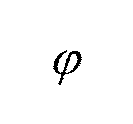
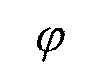
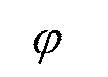
- the conductivity distribution is expressed by ⁇
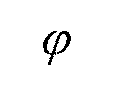
- the potential distribution is ,
- the delta function is represented by ⁇
- the derivative of the delta function is represented by ⁇ ′
- the partial derivative with respect to x is represented by ⁇ x
- the partial derivative with respect to y is represented by ⁇ y
- the conductivity distribution expressed by ⁇ may be derived based on the third relational expression expressed by
- the wave number in the x direction of the magnetic field is expressed by k x
- the wave number in the y direction of the magnetic field is expressed by k y
- the function after Fourier transform of the H x in the x direction and y direction is expressed by Q x
- the function after Fourier transform of H y in the x direction and y direction is expressed by Q y
- the function after Fourier transformation in the x and y directions of the derivation step the relational expression is based on the first relational expression, the second relational expression, and the third relational expression.
- the conductivity distribution may be derived based on a fifth relational expression which is a relational expression expressed by:
- the conductivity distribution may be derived based on the seventh relational expression expressed by:
- the x component of the magnetic field and the y component of the magnetic field are derived and derived based on the conductivity distribution candidate, the potential distribution candidate, and the plurality of relational expressions.
- the conductivity distribution is determined by determining the conductivity distribution candidate as the conductivity distribution. May be derived.
- the conductivity distribution may be derived using GPGPU (General Purpose Graphics Processing Unit) for using the image processing apparatus for a purpose different from the image processing.
- GPGPU General Purpose Graphics Processing Unit
- the conductivity distribution deriving device is a conductivity distribution deriving device that derives a conductivity distribution in a battery having a planar electrode plate, and acquires magnetic field information indicating a magnetic field. And an x component that is a component of the magnetic field and is in the x direction parallel to the electrode plate; and a y component that is a component of the magnetic field and is parallel to the electrode plate and perpendicular to the x direction.
- the magnetic field information based on a plurality of relational expressions satisfying the conductivity distribution on a two-dimensional plane parallel to the electrode plate and the potential distribution on a two-dimensional plane parallel to the electrode plate.
- non-transitory recording medium such as a system, apparatus, method, integrated circuit, computer program, or computer-readable CD-ROM.
- the present invention may be realized by any combination of a method, an integrated circuit, a computer program, and a recording medium.
- FIG. 1 is a diagram illustrating a reference example of a battery inspection method.
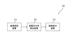
- FIG. 2 is a configuration diagram showing the battery inspection system according to the embodiment.
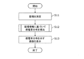
- FIG. 3 is a flowchart showing the operation of the battery inspection system according to the embodiment.
- FIG. 4 is a configuration diagram showing the conductivity distribution deriving device according to the embodiment.
- FIG. 5 is a flowchart showing the operation of the conductivity distribution deriving device according to the embodiment.
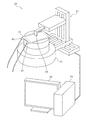
- FIG. 6 is a schematic diagram showing a battery inspection system according to the embodiment.
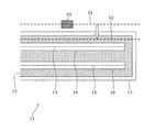
- FIG. 7 is a diagram illustrating a state in which the battery according to the embodiment is being inspected.
- FIG. 8 is a diagram illustrating a coordinate system according to the embodiment.
- FIG. 9 is a diagram for explaining the relationship among the magnetic field, the potential distribution, and the conductivity distribution used by the battery inspection system according to the embodiment.
- FIG. 1 is a diagram illustrating a reference example of a battery inspection method.
- the battery 11 shown in FIG. 1 includes an electrolyte 12, a current collector 13, a positive electrode active material 14, a negative electrode active material 15, a current collector 16, and a metal package 17.
- the electrolyte 12, current collector 13, positive electrode active material 14, negative electrode active material 15, and current collector 16 are covered with a metal package 17.
- Nondestructive inspection includes X-rays, visible light, electron beams, microwaves, and ultrasonic waves.
- X-rays since the transmittance of visible light, electron beam, and microwave is low with respect to the battery 11, it is difficult to inspect the battery 11 based on these in a nondestructive manner.
- the battery 11 can be inspected nondestructively based on X-rays. For example, by inspecting the battery 11 in a non-destructive manner based on X-rays, it is possible to detect that foreign matter is mixed in the battery 11.
- the battery inspection system uses magnetic field information for inspection of the battery 11.
- FIG. 2 is a configuration diagram showing the battery inspection system according to the present embodiment.
- the battery inspection system 20 shown in FIG. 2 includes a magnetic field measurement device 21, a conductivity distribution deriving device 22, and an image display device 23.
- the magnetic field measurement device 21 is a device that measures a magnetic field and includes a sensor and the like. Specifically, the magnetic field measuring device 21 measures the magnetic field around the battery 11.
- the conductivity distribution deriving device 22 is a device that acquires magnetic field information indicating a magnetic field and derives the conductivity distribution inside the battery 11 based on the magnetic field information.
- the conductivity distribution deriving device 22 may be an electronic computer (computer).
- the conductivity distribution derived by the conductivity distribution deriving device 22 is a conductivity distribution inside the battery 11 and a conductivity distribution on a two-dimensional plane parallel to the planar electrode plate included in the battery 11.
- the image display device 23 is a device that displays an image, and includes a display (display unit). Specifically, the image display device 23 displays an image indicating the conductivity distribution derived by the conductivity distribution deriving device 22. The image displayed by the image display device 23 may be generated by the image display device 23 or may be generated by the conductivity distribution deriving device 22.
- FIG. 3 is a flowchart showing the operation of the battery inspection system 20 shown in FIG.
- the magnetic field measuring device 21 measures a magnetic field (S11).
- the conductivity distribution deriving device 22 derives the conductivity distribution based on the magnetic field information (S12).
- the image display device 23 displays an image showing the conductivity distribution (S13).
- the battery inspection system 20 can display an image showing the conductivity distribution inside the battery 11 based on the above operation. An electrical abnormality of the battery 11 appears in the conductivity distribution. That is, the battery inspection system 20 can indicate an electrical abnormality of the battery 11 by displaying an image indicating the conductivity distribution.
- the conductivity distribution is information that directly indicates an electrical abnormality of the battery 11.
- the conductivity distribution is extremely effective for grasping the electrical abnormality of the battery 11.
- the conductivity distribution deriving device 22 for deriving such a conductivity distribution will be described.
- FIG. 4 is a block diagram showing the conductivity distribution deriving device 22 shown in FIG.
- the conductivity distribution deriving device 22 includes an acquisition unit 31 and a deriving unit 32 as shown in FIG.
- the conductivity distribution deriving device 22 may further include an analysis unit that analyzes the magnetic field, or may include a generation unit that generates an image indicating the conductivity distribution.
- Each of these components may be implemented by a dedicated or general purpose circuit. These may be implemented by a single circuit or a plurality of circuits.
- the acquisition unit 31 acquires magnetic field information indicating a magnetic field. For example, the acquisition unit 31 acquires magnetic field information from the magnetic field measurement device 21. The acquisition unit 31 may acquire more detailed magnetic field information by analyzing the magnetic field information acquired from the magnetic field measurement device 21.
- the deriving unit 32 derives the conductivity distribution inside the battery 11 based on the relationship between the magnetic field and the conductivity distribution. More specifically, the deriving unit 32 derives the conductivity distribution based on the relationship among the x-direction component of the magnetic field, the y-direction component of the magnetic field, the conductivity distribution, and the potential distribution. In particular, the deriving unit 32 derives the conductivity distribution based only on the x-direction component of the magnetic field and the y-direction component of the magnetic field, excluding the z-direction component of the magnetic field.
- the x direction and the y direction are two directions parallel to the planar electrode plate included in the battery 11, and are two directions perpendicular to each other.
- the z direction is a direction perpendicular to the x direction and the y direction.
- the conductivity distribution is a conductivity distribution on a two-dimensional plane parallel to the planar electrode plate included in the battery 11.
- the potential distribution is a potential distribution on a two-dimensional plane parallel to the planar electrode plate included in the battery 11.
- the x-direction component of the magnetic field, the y-direction component of the magnetic field, and the z-direction component of the magnetic field may be referred to as the x-component of the magnetic field, the y-component of the magnetic field, and the z-component of the magnetic field, respectively.
- FIG. 5 is a flowchart showing the operation of the conductivity distribution deriving device 22 shown in FIG.
- the acquisition unit 31 acquires magnetic field information (S21).
- the deriving unit 32 derives the conductivity distribution based on the relationship among the x-direction component of the magnetic field, the y-direction component of the magnetic field, the conductivity distribution, and the potential distribution (S22).
- the conductivity distribution deriving device 22 can derive the conductivity distribution based on the above operation.
- FIG. 6 is a schematic diagram showing the battery inspection system 20 shown in FIG. FIG. 6 shows a battery inspection system 20 including a magnetic field measuring device 21, a conductivity distribution deriving device 22, and an image display device 23.
- the magnetic field measuring device 21 has a TMR sensor (Tunneling Magneto Resistive Sensor) 43 as a magnetic sensor.
- the TMR sensor 43 is an example, and other types of sensors may be used.
- the magnetic field measurement device 21 has a slidable mechanism. Thereby, the magnetic field measuring apparatus 21 can scan the vicinity of the battery 11 using the TMR sensor 43.
- the magnetic field measuring device 21 includes a turntable 44.
- the turntable 44 is a stand for placing an inspection object (battery 11), and has a rotatable mechanism. Thereby, the magnetic field measuring device 21 can scan the vicinity of the battery 11 at various rotation angles.
- the conductivity distribution deriving device 22 acquires magnetic field information and derives the conductivity distribution inside the battery 11 based on the magnetic field information.
- the conductivity distribution deriving device 22 is an electronic computer (computer) as shown in FIG.
- the image display device 23 displays an image showing the conductivity distribution.
- the image display device 23 is a display device having a screen as shown in FIG.
- the battery 11 to be inspected by the battery inspection system 20 is a lithium battery or a lithium ion battery.
- the battery 11 has a pair of planar electrode plates.
- the battery 11 has a pair of electrode terminals 41 and 42.
- the magnetic field measuring device 21 measures the magnetic field around the battery 11 in a state where a conducting wire is connected to the electrode terminals 41 and 42 and a current flows.
- FIG. 7 is a diagram showing a state in which the battery 11 shown in FIG. 6 is being inspected. Similar to FIG. 1, the battery 11 shown in FIG. 7 includes an electrolyte 12, a current collector 13, a positive electrode active material 14, a negative electrode active material 15, a current collector 16, and a metal package 17. The electrolyte 12, current collector 13, positive electrode active material 14, negative electrode active material 15, and current collector 16 are covered with a metal package 17.
- the magnetic field measurement device 21 measures the magnetic field via the TMR sensor 43 on the scanning target surface 51 above the battery 11 placed on the turntable 44.
- the conductivity distribution deriving device 22 acquires information on the magnetic field of the reconstruction target surface 52 by acquiring information on the magnetic field measured on the scanning target surface 51 from the magnetic field measurement device 21 and analyzing the acquired information. You may get it. That is, the conductivity distribution deriving device 22 may acquire the magnetic field information of the reconstruction target surface 52 based on the magnetic field information of the scanning target surface 51.
- Patent Literature 2 and Patent Literature 3 describe a method of analyzing Maxwell's equations and analyzing magnetic field information.
- the conductivity distribution deriving device 22 may use the method described in Patent Document 2, Patent Document 3, or the like.
- the magnetic field measurement apparatus 21 may acquire information on the magnetic field of the reconstruction target surface 52 using the method described in Patent Document 2 or Patent Document 3 or the like.
- the conductivity distribution deriving device 22 may acquire information on the magnetic field of the reconstruction target surface 52 from the magnetic field measuring device 21.
- the conductivity distribution deriving device 22 may derive the conductivity distribution based on the magnetic field information of the scanning target surface 51 without acquiring the magnetic field information of the reconstruction target surface 52.
- FIG. 8 is a diagram showing a coordinate system used by the battery inspection system 20 shown in FIG. FIG. 8 shows the relationship between the battery 11 shown in FIG. 6 and the coordinate system.
- the x direction and the y direction are two directions parallel to the planar electrode plate included in the battery 11 and are two directions perpendicular to each other.
- the z direction is a direction perpendicular to the x direction and the y direction.
- the coordinates in the x direction may be expressed as x or x coordinates.
- the coordinates in the y direction may be expressed as y or y coordinates.
- the z-direction coordinate may be expressed as z or z-coordinate.
- the x direction corresponds to the x axis and is also called the x axis direction.
- the y direction corresponds to the y axis and is also called the y axis direction.
- the z direction corresponds to the z axis and is also referred to as the z axis direction.
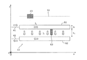
- FIG. 9 is a diagram for explaining the relationship among the magnetic field, the potential distribution, and the conductivity distribution used by the battery inspection system 20 shown in FIG.
- the battery 11 corresponds to a cell of a single-layer lithium ion battery and has a pair of planar electrode plates 61 and 62.
- the electrode plate 61 corresponds to the current collector 13 and the positive electrode active material 14.
- the electrode plate 62 corresponds to the negative electrode active material 15 and the current collector 16.
- the electrolyte 12 is present between the pair of electrode plates 61 and 62.
- the thickness of the electrode plate 61 is represented by h, the distance between the electrode plates 61 and 62 is represented by h T.
- the electrode plate 61 is connected to the electrode terminal 41, and the electrode plate 62 is connected to the electrode terminal 42.
- the magnetic field measurement device 21 measures the magnetic field via the TMR sensor 43 on the scanning target surface 51 above the battery 11 in a state where current is flowing.
- the current is represented by j.
- the current in the x direction is represented by j x
- the current in the y direction is represented by j y
- the current in the z direction is represented by j z .
- the conductivity distribution between the pair of electrode plates 61 and 62 is constant. However, the conductivity distribution changes due to the generation of the dendrite 63.
- the dendrite 63 is formed by depositing metal on the electrode plate 61 or the electrode plate 62.
- the conductivity of the dendrite 63 is higher than that of the electrolyte. For this reason, the dendrite 63 may cause a short circuit. Therefore, the battery inspection system 20 derives the conductivity distribution and inspects the state of the battery 11.
- the conductivity distribution ⁇ (x, y) indicates a conductivity distribution on a two-dimensional plane between the pair of electrode plates 61 and 62.
- Potential distribution Indicates a potential distribution on the two-dimensional plane of the surface of the electrode plate 61.
- the conductivity ⁇ 0 indicates the conductivity of the electrode plate 61.
- the conductivity ⁇ 0 is constant in the electrode plate 61 regardless of the x coordinate or the y coordinate.
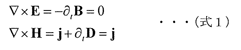
- Equation 1 the relationship of Equation 1 is established based on Maxwell's equation in the steady state.
- E indicates an electric field.
- B represents the magnetic flux density.
- H indicates a magnetic field.
- D indicates the electric flux density.
- t indicates time.
- ⁇ t indicates a partial differential with respect to t.
- the electric field E is expressed as Expression 2 based on the potential (potential).
- the current j in the electrode plate 61 is expressed as in Expression 3 based on the electric field E, the conductivity ⁇ 0 , and Expression 2.
- Expression 4 is established based on the second expression of Expression 1.
- ⁇ is an operator called a Laplace operator or Laplacian.
- Expression 5 is established on the surface of the electrode plate 61.
- H z represents the z component of the magnetic field.
- the current flowing through the electrode plate 61 does not generate the z component H z of the magnetic field.
- a current flowing in parallel in the z direction between the pair of electrode plates 61 and 62 does not generate a z component H z of the magnetic field. This is because the electrode plate 61 of the battery 11 does not have a hole or the like and has a constant conductivity ⁇ 0 unlike a printed board having a via hole.
- Expression 6 is established based on the current continuity expression in the electrode plate 61.
- Equation 6 shows the potential distribution Is expressed as shown in Equation 7.
- Expression 7 is expressed as Expression 8.
- the first term and the second term of the z component coincide. That is, the z component is zero. This means that the current of the battery 11 does not generate the z component H z of the magnetic field, as indicated above.
- the x component and the y component are not zero. Therefore, based on Equation 8 and Equation 10, the magnetic field x component H x , the magnetic field y component H y , the conductivity distribution ⁇ , and the potential distribution. Thus, simultaneous equations as shown in Equation 11 hold.
- the first equation of Equation 11 is the x component H x of the magnetic field, the conductivity distribution ⁇ , and the potential distribution. It is a relational expression which shows the relationship.
- the second equation of Formula 11, and y component H y of the magnetic field, the conductivity distribution sigma, the potential distribution It is a relational expression which shows the relationship.
- the third equation of Equation 11 is the conductivity distribution ⁇ and the potential distribution. It is a relational expression which shows the relationship.
- Equation 11 represents the x component H x of the magnetic field, the y component H y of the magnetic field, the conductivity distribution ⁇ , and the potential distribution.
- the first equation of Equation 11 is the x component H x of the magnetic field, the conductivity distribution ⁇ , and the potential distribution. Is a relational expression that satisfies.
- the second equation of Formula 11, and y component H y of the magnetic field, the conductivity distribution sigma, the potential distribution Is a relational expression that satisfies.
- the third equation of Equation 11 is the conductivity distribution ⁇ and the potential distribution. Is a relational expression that satisfies.
- derivation portion 32 of the conductivity distribution deriving unit 22 includes a x component H x of the magnetic field, the y component H y of the magnetic field, the conductivity distribution sigma, the potential distribution
- the conductivity distribution ⁇ is derived from the magnetic field information based on the equation 11 indicating the relationship between
- the conductivity distribution deriving device 22 can appropriately derive the conductivity distribution ⁇ . Based on the derived conductivity distribution ⁇ , it is possible to appropriately inspect the occurrence of an electrical failure.
- the expression of deriving the conductivity distribution ⁇ based on Expression 11 may include the meaning of deriving the conductivity distribution ⁇ based on an expression that is substantially equal to Expression 11.
- an expression substantially equal to Expression 11 may be an expression obtained by modifying Expression 11 or may be an expression similar to Expression 11.
- the conductivity distribution deriving device 22 is not limited to the equation 11, but the magnetic field x component H x , the magnetic field y component H y , the conductivity distribution ⁇ , and the potential distribution.
- the conductivity distribution ⁇ may be derived on the basis of another relational expression indicating the relation. For example, such a relational expression can be derived based on various physical laws.
- extension example 1 First, extension example 1 will be described.
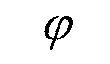
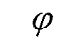
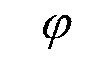
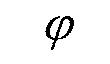
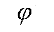
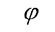
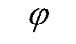
- the deriving unit 32 of the conductivity distribution deriving device 22 includes the model of the conductivity distribution ⁇ and the potential distribution. Model of conductivity distribution ⁇ model and potential distribution Based on the model, the x component H x and the y component H y of the magnetic field are derived. Here, the model is also expressed as a candidate.
- the deriving unit 32 determines the model of the conductivity distribution ⁇ and the potential distribution. Model of conductivity distribution ⁇ and potential distribution respectively And decide.
- the derivation unit 32 determines the conductivity distribution ⁇ model and the potential distribution.
- the model of the conductivity distribution ⁇ and the potential distribution so that the model of Determine the model.
- the model determined first is also expressed as an initial model.
- the initial model may be determined in advance or may be determined based on a user input of the battery inspection system 20. Further, the initial model may be determined based on the characteristics of the battery 11.
- the deriving unit 32 first determines a model of the conductivity distribution ⁇ , and then, based on the third expression of Expression 11, the potential distribution The model may be determined. Alternatively, the derivation unit 32 first determines the potential distribution. And then a model of the conductivity distribution ⁇ may be determined based on the third equation of Equation 11.
- the derivation unit 32 generates a model of the conductivity distribution ⁇ and the potential distribution.
- the x component H x of the magnetic field is derived on the basis of the above model and the first expression of Expression 11.
- the derivation unit 32 includes a model of the conductivity distribution ⁇ and the potential distribution.
- the y component H y of the magnetic field is derived based on the above model and the second equation of Equation 11.
- the derivation unit 32 determines the model of the conductivity distribution ⁇ as the conductivity distribution ⁇ . . In addition, the derivation unit 32 determines the potential distribution in this case. The potential distribution of the model And decide.
- the derivation unit 32 When the derived x component H x and y component H y do not match the magnetic field information acquired by the acquisition unit 31, the derivation unit 32 generates a new model of the conductivity distribution ⁇ , the potential distribution, Determine the new model.
- Deriving unit 32 includes a x component H x derived, the difference between the magnetic field of the x component H x indicated by the magnetic field information, and a y component H y derived, the magnetic field indicated by magnetic field information y component H These new models may be determined based on the difference from y .
- the deriving unit 32 derives the x component H x and the y component H y of the magnetic field based on the newly determined model.
- the deriving unit 32 converts these models into the conductivity distribution ⁇ and the potential distribution. And decide. If the derived x component H x and y component H y do not match the magnetic field information, the deriving unit 32 again determines a new model.
- the derivation unit 32 searches for a model from which the x component H x and the y component H y matching the magnetic field information are derived by repeating the above procedure. That is, the derivation unit 32 derives the x component H x and the y component H y of the magnetic field while changing the model, and the derived x component H x and y component H y are adapted to the magnetic field information.
- Such processing is also processing for searching for an appropriate model from a plurality of models.
- the deriving unit 32 may search for an appropriate model by performing parallel processing on a plurality of models. For example, in this case, the deriving unit 32 derives a plurality of magnetic fields corresponding to a plurality of models in parallel. Then, the deriving unit 32 identifies a magnetic field that matches the magnetic field information from the plurality of magnetic fields, and identifies a model used for deriving the identified magnetic field. Thereby, the deriving unit 32 can search for an appropriate model in a short time.
- the deriving unit 32 may perform such parallel processing by using GPGPU (General Purpose Graphics Processing Unit).
- GPGPU is a method for using an image processing apparatus (image processing unit) for a different purpose from image processing.
- GPGPU is suitable for parallel processing or iterative processing. Therefore, the deriving unit 32 can search for an appropriate model in a shorter time by using GPGPU.
- the deriving unit 32 or the conductivity distribution deriving device 22 may include an image processing device that can be used for the GPGPU.
- Such an image processing apparatus may be a GPGPU apparatus.
- the conductivity distribution deriving device 22 can derive a conductivity distribution that conforms to the relational expression based on repetition of the same kind of calculation. Furthermore, the conductivity distribution deriving device 22 can derive the conductivity distribution ⁇ at high speed by using GPGPU capable of performing the same kind of calculation at high speed.
- extension example 2 Next, extension example 2 will be described.
- the derivation unit 32 of the conductivity distribution deriving device 22 derives the conductivity distribution ⁇ based on a relational expression that can derive the conductivity distribution ⁇ directly from the magnetic field information.
- a relational expression capable of directly deriving the conductivity distribution ⁇ from the magnetic field information is derived from Expression 11.
- the relational expression derived from Expression 11 will be specifically described.
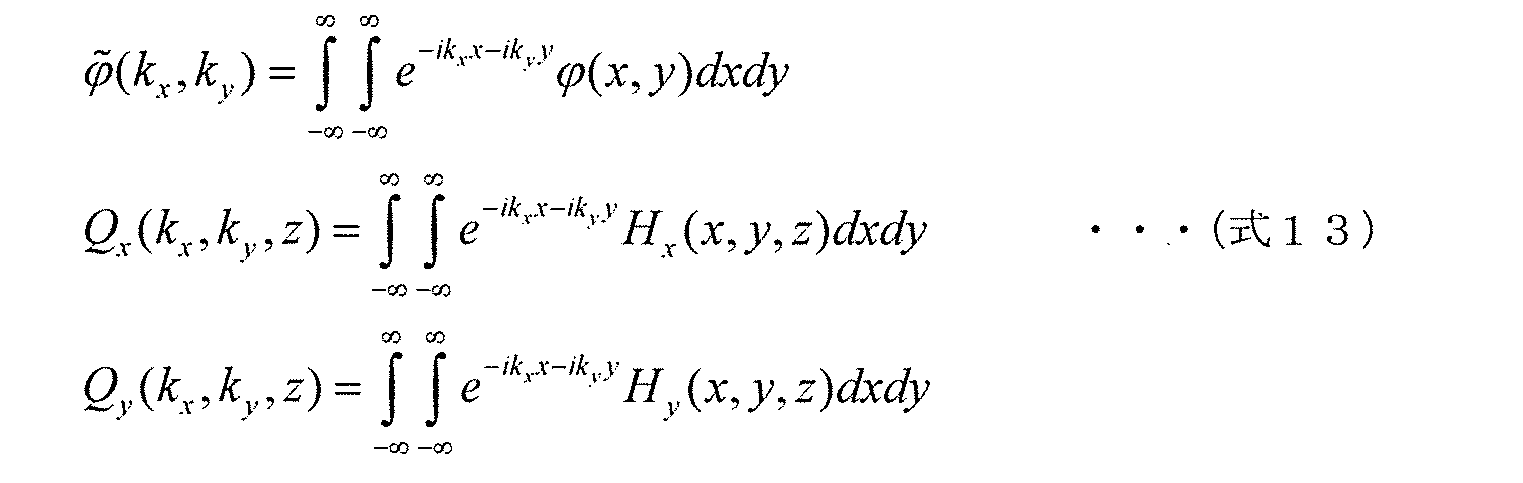
- Expression 14 is derived based on the Fourier transform in the x direction and y direction of Expression 12 and the symbol defined by Expression 13.
- the first expression of Expression 13 is the potential distribution.
- the Fourier-transform image about x direction and y direction is shown.
- the second expression of Expression 13 shows a Fourier transform image of the x component H x of the magnetic field in the x direction and the y direction.
- the third expression of Expression 13 shows a Fourier transform image of the y component H y of the magnetic field in the x direction and the y direction.
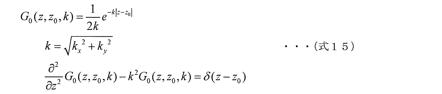
- Equation 19 is derived by combining the first and second equations of Equation 18.
- Equation 19 Based on Equation 19, the potential distribution Equation 20 representing the Fourier transform image of is obtained.
- Expression 20 is a relational expression derived from the first expression, the second expression, and the third expression of Expression 11 by the above procedure, and is a relational expression based on the first expression, the second expression, and the third expression of Expression 11. is there. Potential distribution is obtained by inverse Fourier transform of Equation 20. Is derived. Potential distribution The relational expression for deriving the conductivity distribution ⁇ from the above expression is expressed as Expression 21 based on the third expression of Expression 11.
- the deriving unit 32 of the conductivity distribution deriving device 22 can directly derive the conductivity distribution ⁇ from the magnetic field information based on the equations 20 and 21. That is, the deriving unit 32 can derive the conductivity distribution ⁇ by substituting the magnetic field information into a predetermined calculation formula without repeating the same type of calculation.
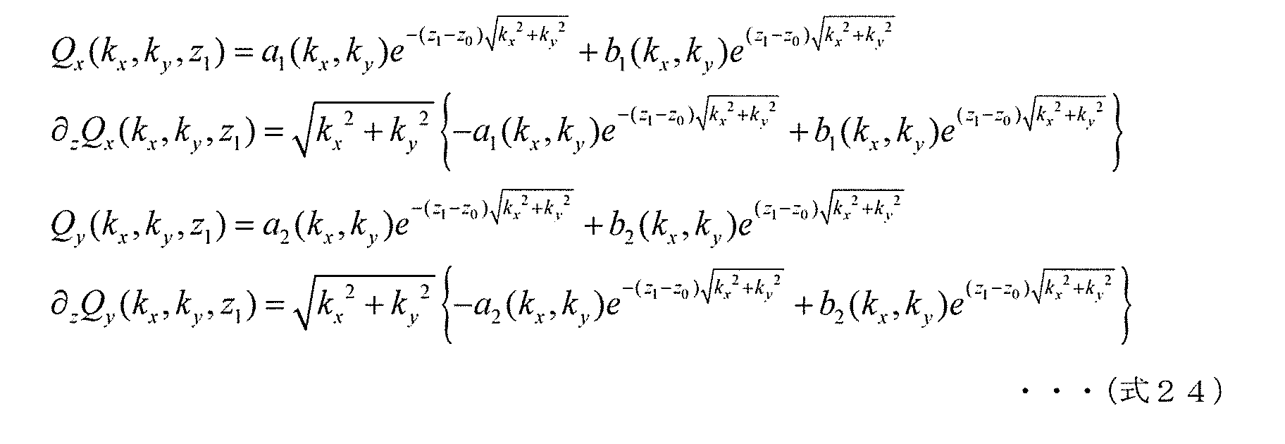
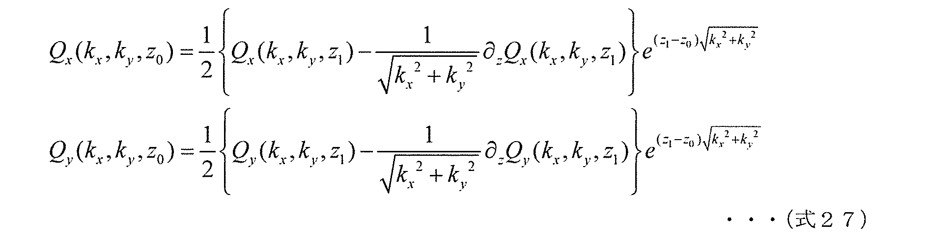
- Q x (k x , k y , z 0 ) and Q y (k x , k y , z 0 ) used in Expression 20 correspond to magnetic field information inside the battery 11. Therefore, next, an arithmetic expression using Q x (k x , k y , z 1 ) and Q y (k x , k y , z 1 ) corresponding to the magnetic field information of the scanning target surface outside the battery 11 will be described. To do. Note that z 1 is the z coordinate of the surface to be scanned and is larger than z 0 .
- Equation 22 the z> z 0, Equation 22 is established. That, z is in the region larger than z 0, Equation 22 is established.
- Equation 23 The general solution for Q x and Q y in the equation of Equation 22 is expressed as Equation 23.
- Equation 25 Solving the algebraic equation shown by Equation 24 for a 1 , b 1 , a 2 and b 2 yields Equation 25.
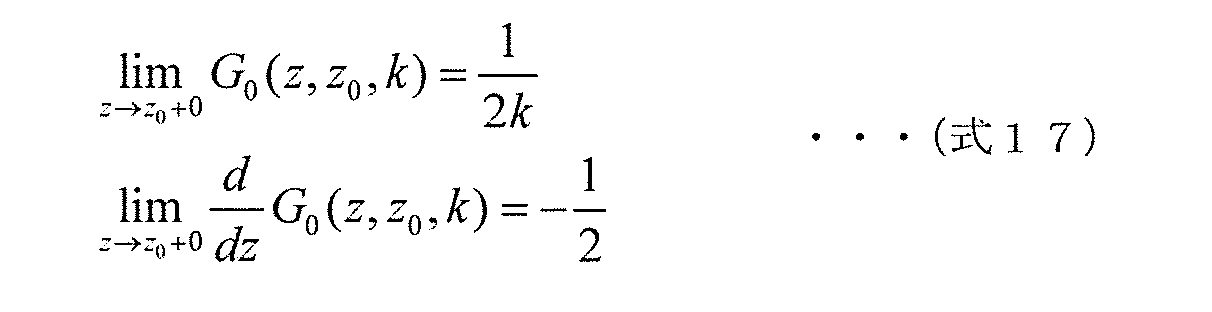
- Equation 26 Based on the consistency with Equations 15 and 16, by setting 0 to b1 and b2 in Equation 23, Equation 26 from which noise has been removed is obtained.
- Equation 27 is obtained. That is, Q x (k x , k y , z 0 ) and Q y (k x , k y , z 0 ), which are information on the magnetic field inside the battery 11, are information on the magnetic field outside the battery 11. Using x (k x , k y , z 1 ) and Q y (k x , k y , z 1 ), it is expressed as in Expression 27.
- the deriving unit 32 of the conductivity distribution deriving device 22 can directly derive the conductivity distribution ⁇ from the magnetic field information outside the battery 11 based on Expression 20, Expression 21, and Expression 27. That is, the derivation unit 32 can derive the conductivity distribution ⁇ by substituting magnetic field information outside the battery 11 into a predetermined calculation formula without repeating the same kind of calculation.
- the battery inspection system and the conductivity distribution deriving device according to the present invention have been described based on the embodiments and the like, but the present invention is not limited to the embodiments. Forms obtained by subjecting the embodiments and the like to modifications conceived by those skilled in the art, and other forms realized by arbitrarily combining a plurality of components in the embodiments and the like are also included in the present invention.
- another processing unit may execute a process executed by a specific processing unit.
- the order in which the processes are executed may be changed, or a plurality of processes may be executed in parallel.
- the battery to be inspected may be a secondary battery or a primary battery.
- the present invention can be realized not only as a battery inspection system or a conductivity distribution deriving device, but also as a method using a processing means constituting the battery inspection system or the conductivity distribution deriving device as a step. For example, these steps are performed by a computer.
- the present invention can be realized as a program for causing a computer to execute the steps included in these methods.
- the present invention can be realized as a non-transitory computer-readable recording medium such as a CD-ROM in which the program is recorded.
- each functional element of the present invention is executed by executing the program using hardware resources such as a CPU, a memory, and an input / output circuit of a computer. Is realized. That is, each functional element is realized by the CPU obtaining data to be processed from a memory or an input / output circuit or the like and calculating the data, or outputting the calculation result to the memory or the input / output circuit or the like.
- the plurality of components included in the battery inspection system or the conductivity distribution deriving device may be realized as an LSI (Large Scale Integration) that is an integrated circuit. These components may be individually made into one chip, or may be made into one chip so as to include a part or all of them. Although referred to here as an LSI, it may be referred to as an IC (Integrated Circuit), a system LSI, a super LSI, or an ultra LSI depending on the degree of integration.
- LSI Large Scale Integration
- the method of circuit integration is not limited to LSI, and implementation with a dedicated circuit or a general-purpose processor is also possible.
- An FPGA Field Programmable Gate Array
- a reconfigurable processor that can reconfigure the connection and setting of circuit cells inside the LSI may be used.
- the conductivity distribution deriving method and the conductivity distribution deriving device according to the present invention can be used for inspection of a short circuit in the battery, and can be used for a battery inspection system for inspecting the occurrence of an electrical failure of the battery. It is.
Landscapes
- General Physics & Mathematics (AREA)
- Physics & Mathematics (AREA)
- Chemical & Material Sciences (AREA)
- Immunology (AREA)
- Health & Medical Sciences (AREA)
- Life Sciences & Earth Sciences (AREA)
- General Health & Medical Sciences (AREA)
- Chemical Kinetics & Catalysis (AREA)
- Electrochemistry (AREA)
- Analytical Chemistry (AREA)
- Pathology (AREA)
- Biochemistry (AREA)
- Secondary Cells (AREA)
- Investigating Or Analyzing Materials By The Use Of Magnetic Means (AREA)
Abstract
Description










図1は、電池の検査方法の参考例を示す図である。図1に示された電池11は、電解質12、集電体13、正極活性物質14、負極活性物質15、集電体16、および、メタルパッケージ17を含む。電解質12、集電体13、正極活性物質14、負極活性物質15、および、集電体16は、メタルパッケージ17で覆われている。




















まず、拡張例1を説明する。拡張例1では、導電率分布導出装置22の導出部32は、導電率分布σのモデルおよび電位分布









次に、拡張例2を説明する。拡張例2では、導電率分布導出装置22の導出部32が、磁場情報から直接的に導電率分布σを導出することが可能な関係式に基づいて、導電率分布σを導出する。磁場情報から直接的に導電率分布σを導出することが可能な関係式は、式11から導出される。以下、式11から導出される関係式を具体的に説明する。













12 電解質
13、16 集電体
14 正極活性物質
15 負極活性物質
17 メタルパッケージ
20 電池検査システム
21 磁場測定装置
22 導電率分布導出装置
23 画像表示装置
31 取得部
32 導出部
41、42 電極端子
43 TMRセンサ(Tunneling Magneto Resistive Sensor)
44 回転台
51 走査対象面
52 再構成対象面
61、62 電極板
63 デンドライト
Claims (8)
- 平面状の電極板を有する電池内の導電率分布を導出する導電率分布導出方法であって、
磁場を示す磁場情報を取得する取得ステップと、
前記磁場の成分であり前記電極板に平行なx方向の成分であるx成分と、前記磁場の成分であり前記電極板に平行かつx方向に垂直なy方向の成分であるy成分と、前記電極板に平行な2次元平面上の前記導電率分布と、前記電極板に平行な2次元平面上の電位分布とが満たす複数の関係式に基づいて、前記磁場情報に対して前記複数の関係式を満たす前記導電率分布を導出する導出ステップとを含む
導電率分布導出方法。 - 前記複数の関係式は、(i)前記磁場のx成分と、前記導電率分布と、前記電位分布との関係を示す第1関係式と、(ii)前記磁場のy成分と、前記導電率分布と、前記電位分布との関係を示す第2関係式と、(iii)前記導電率分布と、前記電位分布との関係を示す第3関係式とを含み、
前記導出ステップでは、前記第1関係式と前記第2関係式と前記第3関係式とに基づいて、前記導電率分布を導出する
請求項1に記載の導電率分布導出方法。 - x方向の座標がxで表現され、y方向の座標がyで表現され、x方向およびy方向に垂直なz方向の座標がzで表現され、前記電極板のz方向の座標がz0で表現され、前記磁場のx成分がHxで表現され、前記磁場のy成分がHyで表現され、前記電極板のz方向の厚さがhで表現され、前記電極板を含む1対の電極板の間の距離がhTで表現され、前記電極板の導電率がσ0で表現され、前記導電率分布がσで表現され、前記電位分布が
前記導出ステップでは、



で表現される前記第3関係式とに基づいて、σで表現される前記導電率分布を導出する
請求項2に記載の導電率分布導出方法。 - 前記磁場のx方向の波数がkxで表現され、前記磁場のy方向の波数がkyで表現され、Hxのx方向およびy方向についてのフーリエ変換後の関数がQxで表現され、Hyのx方向およびy方向についてのフーリエ変換後の関数がQyで表現され、


前記導出ステップでは、前記第1関係式と前記第2関係式と前記第3関係式とに基づく関係式であり、


請求項3に記載の導電率分布導出方法。 - 前記電池の外部のz方向の座標がz1で表現され、zについての偏微分が∂zで表現される場合、
前記導出ステップでは、前記第4関係式と、前記第5関係式と、


請求項4に記載の導電率分布導出方法。 - 前記導出ステップでは、
前記導電率分布の候補と、前記電位分布の候補と、前記複数の関係式とに基づいて、前記磁場のx成分と、前記磁場のy成分とを導出し、
導出された前記x成分と、導出された前記y成分とが、前記磁場情報によって示される前記磁場に適合する場合、前記導電率分布の候補を前記導電率分布と決定することにより、前記導電率分布を導出する
請求項1~3のいずれか1項に記載の導電率分布導出方法。 - 前記導出ステップでは、画像処理装置を画像処理とは異なる用途に利用するためのGPGPU(General Purpose Graphics Processing Unit)を利用して、前記導電率分布を導出する
請求項6に記載の導電率分布導出方法。 - 平面状の電極板を有する電池内の導電率分布を導出する導電率分布導出装置であって、
磁場を示す磁場情報を取得する取得部と、
前記磁場の成分であり前記電極板に平行なx方向の成分であるx成分と、前記磁場の成分であり前記電極板に平行かつx方向に垂直なy方向の成分であるy成分と、前記電極板に平行な2次元平面上の前記導電率分布と、前記電極板に平行な2次元平面上の電位分布とが満たす複数の関係式に基づいて、前記磁場情報に対して前記複数の関係式を満たす前記導電率分布を導出する導出部とを備える
導電率分布導出装置。
Priority Applications (2)
| Application Number | Priority Date | Filing Date | Title |
|---|---|---|---|
| JP2016507363A JP6521261B2 (ja) | 2014-03-12 | 2015-03-11 | 導電率分布導出方法および導電率分布導出装置 |
| US15/124,874 US10254352B2 (en) | 2014-03-12 | 2015-03-11 | Conductivity distribution derivation method and conductivity distribution derivation device |
Applications Claiming Priority (2)
| Application Number | Priority Date | Filing Date | Title |
|---|---|---|---|
| JP2014049513 | 2014-03-12 | ||
| JP2014-049513 | 2014-03-12 |
Publications (1)
| Publication Number | Publication Date |
|---|---|
| WO2015136931A1 true WO2015136931A1 (ja) | 2015-09-17 |
Family
ID=54071388
Family Applications (1)
| Application Number | Title | Priority Date | Filing Date |
|---|---|---|---|
| PCT/JP2015/001344 Ceased WO2015136931A1 (ja) | 2014-03-12 | 2015-03-11 | 導電率分布導出方法および導電率分布導出装置 |
Country Status (3)
| Country | Link |
|---|---|
| US (1) | US10254352B2 (ja) |
| JP (1) | JP6521261B2 (ja) |
| WO (1) | WO2015136931A1 (ja) |
Cited By (7)
| Publication number | Priority date | Publication date | Assignee | Title |
|---|---|---|---|---|
| WO2017187791A1 (ja) * | 2016-04-28 | 2017-11-02 | 国立大学法人神戸大学 | 計測装置および計測方法 |
| JPWO2017086325A1 (ja) * | 2015-11-16 | 2018-09-06 | 国立大学法人神戸大学 | 観測方法および観測装置 |
| EP3644081A1 (en) | 2018-10-26 | 2020-04-29 | Sumida Corporation | Magnetic field source detecting apparatus and magnetic field source detecting method |
| US10969445B2 (en) | 2018-07-03 | 2021-04-06 | Sumida Corporation | Magnetic field measurement apparatus and magnetic field measurement method |
| US11417917B2 (en) | 2019-05-16 | 2022-08-16 | Toyota Jidosha Kabushiki Kaisha | Method of testing battery, battery testing apparatus, and battery |
| JPWO2024009894A1 (ja) * | 2022-07-07 | 2024-01-11 | ||
| WO2025004516A1 (ja) * | 2023-06-26 | 2025-01-02 | 株式会社 Integral Geometry Science | 蓄電池検査装置及び蓄電池検査方法 |
Citations (4)
| Publication number | Priority date | Publication date | Assignee | Title |
|---|---|---|---|---|
| JP2003222664A (ja) * | 2001-11-15 | 2003-08-08 | Chikayoshi Sumi | 電流密度ベクトル推定装置および電気導電率推定装置 |
| WO2006109382A1 (ja) * | 2005-03-14 | 2006-10-19 | National University Corporation Okayama University | 磁気的インピーダンス計測装置 |
| JP2009074953A (ja) * | 2007-09-21 | 2009-04-09 | Kyushu Univ | 電磁探査装置、電磁探査方法及びプログラム |
| JP2009229337A (ja) * | 2008-03-25 | 2009-10-08 | Hioki Ee Corp | 電極検査装置 |
Family Cites Families (6)
| Publication number | Priority date | Publication date | Assignee | Title |
|---|---|---|---|---|
| JP4103713B2 (ja) * | 2003-07-18 | 2008-06-18 | 株式会社デンソー | 電流検出器 |
| US6975108B2 (en) * | 2003-11-13 | 2005-12-13 | Yuli Bilik | Methods and devices for eddy current PCB inspection |
| US7250757B1 (en) * | 2004-09-16 | 2007-07-31 | Radiation Monitoring Devices, Inc. | Apparatus and method for circuit analysis using magnetic and electromagnetic stimulation of the circuit for dual magnetic field imaging |
| US8536862B2 (en) | 2007-03-30 | 2013-09-17 | Kyoto University | Apparatus and method of obtaining field by measurement |
| DE102009018079A1 (de) | 2009-04-20 | 2010-10-21 | Li-Tec Battery Gmbh | Verfahren zum Betrieb einer Batterie |
| WO2012153496A1 (ja) | 2011-05-09 | 2012-11-15 | 国立大学法人神戸大学 | 分布解析装置 |
-
2015
- 2015-03-11 US US15/124,874 patent/US10254352B2/en active Active
- 2015-03-11 JP JP2016507363A patent/JP6521261B2/ja active Active
- 2015-03-11 WO PCT/JP2015/001344 patent/WO2015136931A1/ja not_active Ceased
Patent Citations (4)
| Publication number | Priority date | Publication date | Assignee | Title |
|---|---|---|---|---|
| JP2003222664A (ja) * | 2001-11-15 | 2003-08-08 | Chikayoshi Sumi | 電流密度ベクトル推定装置および電気導電率推定装置 |
| WO2006109382A1 (ja) * | 2005-03-14 | 2006-10-19 | National University Corporation Okayama University | 磁気的インピーダンス計測装置 |
| JP2009074953A (ja) * | 2007-09-21 | 2009-04-09 | Kyushu Univ | 電磁探査装置、電磁探査方法及びプログラム |
| JP2009229337A (ja) * | 2008-03-25 | 2009-10-08 | Hioki Ee Corp | 電極検査装置 |
Non-Patent Citations (4)
| Title |
|---|
| BRADLEY J. ROTH ET AL.: "Using a magnetometer to image a two-dimensional current distribution", JOURNAL OF APPLIED PHYSICS, vol. 65, no. 1, 1989, pages 361 - 372, XP000093117, ISSN: 0021-8979 * |
| CHIKAYOSHI SUMI ET AL.: "Determination of the spatial distribution of a physical parameter from the distribution of another physical variable- a differential inverse problem", J.APPL.PHYS., vol. 80, no. 1, 1996, pages 1 - 7, XP055224431, ISSN: 0021-8979 * |
| KENJIRO KIMURA ET AL.: "Denjiba Saikoseiho to Sosagata Tunnel Jiki Teiko Koka Kenbikyo no Kaihatsu", ELECTRONIC PACKAGING TECHNOLOGY, vol. 28, no. 2, 20 January 2012 (2012-01-20), pages 16 - 20 * |
| YUKI MIMA ET AL.: "Denjiba Saikosei Tunnel Jiki Teiko Koka Kenbikyo no Kaihatsu to Denchi Naibu ni Okeru Denka Ido Kashika eno Oyo", DAI 54 KAI ABSTRACTS, BATTERY SYMPOSIUM IN JAPAN, 6 October 2013 (2013-10-06), pages 423 * |
Cited By (17)
| Publication number | Priority date | Publication date | Assignee | Title |
|---|---|---|---|---|
| JPWO2017086325A1 (ja) * | 2015-11-16 | 2018-09-06 | 国立大学法人神戸大学 | 観測方法および観測装置 |
| US11041826B2 (en) | 2015-11-16 | 2021-06-22 | National University Corporation Kobe University | Observation method and observation device |
| US11422110B2 (en) | 2015-11-16 | 2022-08-23 | National University Corporation Kobe University | Observation method and observation device |
| JPWO2017187791A1 (ja) * | 2016-04-28 | 2019-02-28 | 国立大学法人神戸大学 | 計測装置および計測方法 |
| US11366079B2 (en) | 2016-04-28 | 2022-06-21 | National University Corporation Kobe University | Measurement device and measurement method |
| WO2017187791A1 (ja) * | 2016-04-28 | 2017-11-02 | 国立大学法人神戸大学 | 計測装置および計測方法 |
| US11619687B2 (en) | 2018-07-03 | 2023-04-04 | Sumida Corporation | Magnetic field measurement apparatus and magnetic field measurement method |
| US10969445B2 (en) | 2018-07-03 | 2021-04-06 | Sumida Corporation | Magnetic field measurement apparatus and magnetic field measurement method |
| EP3644081A1 (en) | 2018-10-26 | 2020-04-29 | Sumida Corporation | Magnetic field source detecting apparatus and magnetic field source detecting method |
| US11067646B2 (en) | 2018-10-26 | 2021-07-20 | Sumida Corporation | Magnetic field source detecting apparatus and magnetic field source detecting method |
| US11543467B2 (en) | 2018-10-26 | 2023-01-03 | Sumida Corporation | Magnetic field source detecting apparatus and magnetic field source detecting method |
| US11417917B2 (en) | 2019-05-16 | 2022-08-16 | Toyota Jidosha Kabushiki Kaisha | Method of testing battery, battery testing apparatus, and battery |
| JPWO2024009894A1 (ja) * | 2022-07-07 | 2024-01-11 | ||
| WO2024009894A1 (ja) * | 2022-07-07 | 2024-01-11 | 株式会社 Integral Geometry Science | 測定装置および測定方法 |
| KR20240110827A (ko) | 2022-07-07 | 2024-07-16 | 가부시키가이샤 인테그랄 지오메트리 사이언스 | 측정 장치 및 측정 방법 |
| JP7616735B2 (ja) | 2022-07-07 | 2025-01-17 | 株式会社 Integral Geometry Science | 測定装置および測定方法 |
| WO2025004516A1 (ja) * | 2023-06-26 | 2025-01-02 | 株式会社 Integral Geometry Science | 蓄電池検査装置及び蓄電池検査方法 |
Also Published As
| Publication number | Publication date |
|---|---|
| US10254352B2 (en) | 2019-04-09 |
| JPWO2015136931A1 (ja) | 2017-04-06 |
| US20170016963A1 (en) | 2017-01-19 |
| JP6521261B2 (ja) | 2019-05-29 |
Similar Documents
| Publication | Publication Date | Title |
|---|---|---|
| JP6521261B2 (ja) | 導電率分布導出方法および導電率分布導出装置 | |
| US9739843B2 (en) | Arrangement and method for characterizing magnetic systems | |
| Barbato et al. | Solution and extension of a new benchmark problem for eddy-current nondestructive testing | |
| US11422110B2 (en) | Observation method and observation device | |
| Miorelli et al. | Efficient modeling of ECT signals for realistic cracks in layered half-space | |
| EP2708884B1 (en) | Distribution analysis device | |
| CN104182648B (zh) | 反演航天器内部多磁源分布的方法 | |
| KR101521190B1 (ko) | 제조 툴에 대한 레시피를 생성하는 방법 및 그 시스템 | |
| CN111458573A (zh) | 导线电力参数测量方法、装置、系统和计算机设备 | |
| WO2014129151A1 (ja) | 分布解析装置および分布解析方法 | |
| CN109298069B (zh) | 多层金属结构快速检测方法及其装置、设备和存储介质 | |
| Jayasudha et al. | Weld defect segmentation and feature extraction from the acquired phased array scan images | |
| JP6461095B2 (ja) | 電池検査装置および電池検査方法 | |
| CN117893513A (zh) | 一种基于视觉神经网络算法的pcb板检测方法及系统 | |
| CN112285435A (zh) | 一种大功率磁场辐射源的等效模拟方法 | |
| Zhang et al. | Mechanism study for directivity of TR probe when applying Eddy current testing to ferro-magnetic structural materials | |
| JPWO2017187791A1 (ja) | 計測装置および計測方法 | |
| KR101967044B1 (ko) | 블레이드 표면검사방법 및 표면검사장치 | |
| CN118348067B (zh) | 一种电力设备金属组件的缺陷检测方法及装置 | |
| Le Bihan et al. | Calculation of the ECT signal of a minute crack by a FEM-BIM hybrid method | |
| Efremov | Novel Simulation and Data Processing Algorithms for Eddy Current Inspection | |
| Jesenik et al. | Finding a Crack and Determining Depth in a Material | |
| CN111458403A (zh) | 阵列涡流检测方法及系统 | |
| Kovács et al. | Simulation of a developed magnetic flux leakage method | |
| Madathil | Modeling of Radiation Source Using an Equivalent Dipole Moment Model |
Legal Events
| Date | Code | Title | Description |
|---|---|---|---|
| 121 | Ep: the epo has been informed by wipo that ep was designated in this application |
Ref document number: 15761031 Country of ref document: EP Kind code of ref document: A1 |
|
| ENP | Entry into the national phase |
Ref document number: 2016507363 Country of ref document: JP Kind code of ref document: A |
|
| WWE | Wipo information: entry into national phase |
Ref document number: 15124874 Country of ref document: US |
|
| NENP | Non-entry into the national phase |
Ref country code: DE |
|
| 122 | Ep: pct application non-entry in european phase |
Ref document number: 15761031 Country of ref document: EP Kind code of ref document: A1 |