図1は、本発明が適用される建設機械の一例であるショベルを示す側面図である。ショベルの下部走行体1には、旋回機構2を介して上部旋回体3が搭載されている。上部旋回体3には、ブーム4が取り付けられている。ブーム4の先端にはアーム5が取り付けられ、アーム5の先端にはバケット6が取り付けられている。ブーム4、アーム5、及びバケット6は、作業アタッチメントの1例である掘削アタッチメントを構成し、ブームシリンダ7、アームシリンダ8、及びバケットシリンダ9によりそれぞれ油圧駆動される。上部旋回体3には、キャビン10が設けられ、且つエンジン等の動力源が搭載される。
FIG. 1 is a side view showing an excavator as an example of a construction machine to which the present invention is applied. An upper swing body 3 is mounted on the lower traveling body 1 of the excavator via a swing mechanism 2. A boom 4 is attached to the upper swing body 3. An arm 5 is attached to the tip of the boom 4, and a bucket 6 is attached to the tip of the arm 5. The boom 4, the arm 5, and the bucket 6 constitute an excavation attachment that is an example of a work attachment, and are hydraulically driven by a boom cylinder 7, an arm cylinder 8, and a bucket cylinder 9. The upper swing body 3 is provided with a cabin 10 and is mounted with a power source such as an engine.
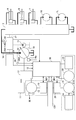
図2は、本発明の実施例に係るショベルの駆動系の構成例を示すブロック図である。図2において、機械的動力系は二重線、高圧油圧ラインは太実線、パイロットラインは破線、電気駆動・制御系は細実線でそれぞれ示されている。
FIG. 2 is a block diagram showing a configuration example of a drive system of the shovel according to the embodiment of the present invention. In FIG. 2, the mechanical power system is indicated by a double line, the high-pressure hydraulic line is indicated by a thick solid line, the pilot line is indicated by a broken line, and the electric drive / control system is indicated by a thin solid line.
機械式駆動部としてのエンジン11と、アシスト駆動部としての電動発電機12は、変速機13の2つの入力軸にそれぞれ接続されている。変速機13の出力軸には、油圧ポンプとしてメインポンプ14及びパイロットポンプ15が接続されている。メインポンプ14には、高圧油圧ライン16を介してコントロールバルブ17が接続されている。メインポンプ14とコントロールバルブ17内の各バルブとは並列接続されていてもよい。
The engine 11 as a mechanical drive unit and the motor generator 12 as an assist drive unit are connected to two input shafts of a transmission 13, respectively. A main pump 14 and a pilot pump 15 are connected to the output shaft of the transmission 13 as hydraulic pumps. A control valve 17 is connected to the main pump 14 via a high pressure hydraulic line 16. The main pump 14 and each valve in the control valve 17 may be connected in parallel.
メインポンプ14は、ショベルにおける油圧駆動系の構成要素であり、本実施例では斜板式可変容量型油圧ポンプである。
The main pump 14 is a component of a hydraulic drive system in the excavator, and is a swash plate type variable displacement hydraulic pump in this embodiment.
レギュレータ14aは、メインポンプ14の吐出量を制御する装置である。本実施例では、レギュレータ14aは、コントローラ30からの指令に応じてメインポンプ14の斜板傾転角を調整してメインポンプ14の吐出量を制御する。
The regulator 14 a is a device that controls the discharge amount of the main pump 14. In this embodiment, the regulator 14 a controls the discharge amount of the main pump 14 by adjusting the swash plate tilt angle of the main pump 14 in accordance with a command from the controller 30.
コントロールバルブ17は、ショベルにおける油圧系の制御を行う油圧制御装置である。右側走行用油圧モータ1R、左側走行用油圧モータ1L、ブームシリンダ7、アームシリンダ8、バケットシリンダ9等の油圧アクチュエータは、高圧油圧ラインを介してコントロールバルブ17に接続される。なお、油圧系は、右側走行用油圧モータ1R、左側走行用油圧モータ1L、ブームシリンダ7、アームシリンダ8、バケットシリンダ9、メインポンプ14、コントロールバルブ17を含む。
The control valve 17 is a hydraulic control device that controls a hydraulic system in the excavator. The hydraulic actuators such as the right traveling hydraulic motor 1R, the left traveling hydraulic motor 1L, the boom cylinder 7, the arm cylinder 8, and the bucket cylinder 9 are connected to the control valve 17 via a high pressure hydraulic line. The hydraulic system includes a right traveling hydraulic motor 1R, a left traveling hydraulic motor 1L, a boom cylinder 7, an arm cylinder 8, a bucket cylinder 9, a main pump 14, and a control valve 17.
電動発電機12には、電動発電機制御部としてのインバータ18を介して、蓄電器としてのキャパシタを含む蓄電系120が接続される。また、蓄電系120には、電動発電機制御部としてのインバータ20を介して電動作業要素としての旋回用電動機21が接続されている。旋回用電動機21の回転軸21Aには、レゾルバ22、メカニカルブレーキ23、及び旋回変速機24が接続される。また、パイロットポンプ15には、パイロットライン25を介して操作装置26が接続される。旋回用電動機21と、インバータ20と、レゾルバ22と、メカニカルブレーキ23と、旋回変速機24とで負荷駆動系としての電動旋回系が構成される。旋回用電動機21は旋回駆動の機能を有し上部旋回体3を回転させる。旋回系として油圧の駆動・ブレーキ系を備える構成でもよい。本実施例は特に旋回駆動に油圧を用いない構成で顕著な効果を発揮する。以下、旋回駆動に油圧を用いない構成について説明する。
The motor generator 12 is connected to a power storage system 120 including a capacitor as a capacitor via an inverter 18 as a motor generator control unit. The power storage system 120 is connected to a turning electric motor 21 as an electric working element via an inverter 20 as a motor generator control unit. A resolver 22, a mechanical brake 23, and a turning transmission 24 are connected to the rotating shaft 21 </ b> A of the turning electric motor 21. An operation device 26 is connected to the pilot pump 15 through a pilot line 25. The turning electric motor 21, the inverter 20, the resolver 22, the mechanical brake 23, and the turning transmission 24 constitute an electric turning system as a load drive system. The turning electric motor 21 has a turning drive function and rotates the upper turning body 3. A configuration including a hydraulic drive / brake system as a turning system may be used. This embodiment exhibits a remarkable effect particularly in a configuration in which no hydraulic pressure is used for turning driving. Hereinafter, a configuration in which hydraulic pressure is not used for turning driving will be described.
操作装置26は、操作量に関連した情報を生成する。情報はそのまま或いは変換されて駆動装置又はその他の装置に対して直接的に或いはコントローラ30等を介在させて間接的に供給され得る。操作装置26は、レバー26A、レバー26B、ペダル26Cを含む。レバー26A、レバー26B、及びペダル26Cは、油圧ライン27及び28を介して、コントロールバルブ17及び圧力センサ29にそれぞれ接続される。
The operation device 26 generates information related to the operation amount. The information can be supplied directly or converted to the drive device or other device directly or indirectly through the controller 30 or the like. The operating device 26 includes a lever 26A, a lever 26B, and a pedal 26C. The lever 26A, the lever 26B, and the pedal 26C are connected to the control valve 17 and the pressure sensor 29 via hydraulic lines 27 and 28, respectively.
圧力センサ29は、操作装置26の操作内容を圧力の形で検出するセンサであり、検出値をコントローラ30に対して出力する。
The pressure sensor 29 is a sensor that detects the operation content of the operation device 26 in the form of pressure, and outputs a detection value to the controller 30.
吐出圧センサ29Aは、メインポンプ14の吐出圧を検出するセンサであり、検出値をコントローラ30に対して出力する。
The discharge pressure sensor 29 </ b> A is a sensor that detects the discharge pressure of the main pump 14, and outputs a detection value to the controller 30.
温度センサM2、M3は、蓄電系120の温度を検出するセンサであり、検出値をコントローラ30に対して出力する。本実施例では、温度センサM2、M3は、サーミスタで構成され、検出値をコントローラ30に対して出力する。
Temperature sensors M2 and M3 are sensors that detect the temperature of the power storage system 120, and output detected values to the controller 30. In this embodiment, the temperature sensors M <b> 2 and M <b> 3 are composed of thermistors and output detection values to the controller 30.
コントローラ30は、ショベルの駆動制御を行う主制御部としての制御装置である。本実施例では、コントローラ30は、CPU及び内部メモリを含む演算処理装置で構成され、内部メモリに格納された駆動制御用のプログラムをCPUに実行させて各種機能を実現する。
The controller 30 is a control device as a main control unit that performs drive control of the excavator. In the present embodiment, the controller 30 is configured by an arithmetic processing unit including a CPU and an internal memory, and realizes various functions by causing the CPU to execute a drive control program stored in the internal memory.
また、コントローラ30は、例えば、圧力センサ29、吐出圧センサ29A、温度センサM2、及び温度センサM3からの検出値を受けて各種演算を実行し、エンジン11、レギュレータ14a、蓄電系120等に各種指令を出力する。例えば、コントローラ30は、温度センサM2の検出値に基づいて蓄電系120の温度が所定温度未満であると判断した場合に蓄電系120の暖機を開始させる。また、コントローラ30は、圧力センサ29及び吐出圧センサ29Aの検出値に基づいて油圧駆動系の暖機が開始されたと判断した場合であっても、蓄電系120の暖機を継続させる。なお、油圧駆動系の暖機及び蓄電系120の暖機に関する詳細な説明は後述される。
In addition, the controller 30 receives various detection values from the pressure sensor 29, the discharge pressure sensor 29A, the temperature sensor M2, and the temperature sensor M3, for example, and executes various calculations to apply various calculations to the engine 11, the regulator 14a, the power storage system 120, and the like. Output a command. For example, when controller 30 determines that the temperature of power storage system 120 is lower than a predetermined temperature based on the detected value of temperature sensor M2, warm-up of power storage system 120 is started. Further, the controller 30 continues warming up of the power storage system 120 even when it is determined that warming up of the hydraulic drive system has started based on the detection values of the pressure sensor 29 and the discharge pressure sensor 29A. A detailed description of the warm-up of the hydraulic drive system and the warm-up of the power storage system 120 will be described later.
図3は蓄電系120の構成を示すブロック図である。蓄電系120は、第1の蓄電器としてのキャパシタ19と、昇降圧コンバータ100と、バスラインとしてのDCバス110とを含む。なお、第1の蓄電器は、電力を充放電可能な装置であり、例えば、リチウムイオンキャパシタ、電気二重層キャパシタ、リチウムイオン電池等である。本実施例では、キャパシタ19は、リチウムイオンキャパシタである。
FIG. 3 is a block diagram showing the configuration of the power storage system 120. The power storage system 120 includes a capacitor 19 as a first battery, a buck-boost converter 100, and a DC bus 110 as a bus line. The first battery is a device that can charge and discharge electric power, such as a lithium ion capacitor, an electric double layer capacitor, and a lithium ion battery. In this embodiment, the capacitor 19 is a lithium ion capacitor.
蓄電系120には、キャパシタ電圧値を検出するためのキャパシタ電圧検出部112と、キャパシタ電流値を検出するためのキャパシタ電流検出部113が設けられている。キャパシタ電圧値とキャパシタ電流値は、コントローラ30に供給される。
The power storage system 120 is provided with a capacitor voltage detector 112 for detecting the capacitor voltage value and a capacitor current detector 113 for detecting the capacitor current value. The capacitor voltage value and the capacitor current value are supplied to the controller 30.
キャパシタ電圧値は、キャパシタ19の端子電圧に相当する。キャパシタ19の開放電圧をVc[V]とし、キャパシタ19の内部抵抗をR[Ω]とし、キャパシタ19から昇降圧コンバータ100に流れる放電電流の大きさをId[A]とすると、キャパシタ19の放電時の端子電圧V1は、V1=Vc-R×Idで表され、キャパシタ19の放電電力W1は、W1=V1×Idで表される。また、昇降圧コンバータ100からキャパシタ19に流れる充電電流の大きさをIcとすると、キャパシタ19の充電時の端子電圧V2は、V2=Vc+R×Icで表され、キャパシタ19の充電電力W2は、W2=V2×Icで表される。
The capacitor voltage value corresponds to the terminal voltage of the capacitor 19. When the open-circuit voltage of the capacitor 19 is Vc [V], the internal resistance of the capacitor 19 is R [Ω], and the magnitude of the discharge current flowing from the capacitor 19 to the buck-boost converter 100 is Id [A], the discharge of the capacitor 19 The terminal voltage V1 at that time is represented by V1 = Vc−R × Id, and the discharge power W1 of the capacitor 19 is represented by W1 = V1 × Id. Further, assuming that the charging current flowing from the buck-boost converter 100 to the capacitor 19 is Ic, the terminal voltage V2 at the time of charging the capacitor 19 is expressed by V2 = Vc + R × Ic, and the charging power W2 of the capacitor 19 is W2 = V2 × Ic.
また、キャパシタ19の放電時の発熱量Q1はId2×Rで表され、充電時の発熱量Q2はIc2×Rで表される。
Further, the calorific value Q1 during discharging of the capacitor 19 is represented by Id 2 × R, and the calorific value Q2 during charging is represented by Ic 2 × R.
また、キャパシタ19の充電率(SOC)は、キャパシタ19の最小電圧をVminとし、最大電圧をVmaxとすると、以下の式で表される。
Further, the charging rate (SOC) of the capacitor 19 is expressed by the following equation, where the minimum voltage of the capacitor 19 is Vmin and the maximum voltage is Vmax.
以上の関係から、キャパシタ19のSOCが高いことは開放電圧Vcが高いことを意味し、所定の放電電力W1を実現する場合の放電電流Idが小さくて済み、放電時の発熱量Q1も小さくなるため、放電効率が高い。同様に、所定の充電電力W2を実現する場合の充電電流Icが小さくて済み、充電時の発熱量Q2も小さくなるため、充電効率が高い。
From the above relationship, the high SOC of the capacitor 19 means that the open circuit voltage Vc is high, the discharge current Id when realizing the predetermined discharge power W1 can be small, and the heat generation amount Q1 during discharge is also small. Therefore, the discharge efficiency is high. Similarly, the charging current Ic for realizing the predetermined charging power W2 is small, and the heat generation amount Q2 at the time of charging is also small, so that the charging efficiency is high.
また、蓄電系120に設けられている温度センサM2は、キャパシタ19の温度(キャパシタ温度)を検出する。温度センサM3は、昇降圧コンバータ100の温度を検出する。キャパシタ温度は、キャパシタ19の温度の適当な基準に対する相対値が分かる態様で検出されればよく、通常は直接測定される。キャパシタ温度に関連する情報が用いられてもよい。例えば、キャパシタ19の冷却に用いられる冷却水の温度を検出することで間接的に検出されてもよい。また、キャパシタ19の温度に影響する冷却水以外の他の熱媒体の温度を検出することで間接的に検出されてもよい。気温等の環境温度でもよい。例えば、温度センサM2は、キャパシタセルの電極に取り付けられたサーミスタで構成され、キャパシタ温度を検出し、その検出値をコントローラ30に対して出力する。
The temperature sensor M2 provided in the power storage system 120 detects the temperature of the capacitor 19 (capacitor temperature). The temperature sensor M3 detects the temperature of the buck-boost converter 100. The capacitor temperature may be detected in such a manner that the relative value of the temperature of the capacitor 19 with respect to an appropriate reference is known, and is usually measured directly. Information related to the capacitor temperature may be used. For example, it may be detected indirectly by detecting the temperature of the cooling water used for cooling the capacitor 19. Alternatively, it may be detected indirectly by detecting the temperature of a heat medium other than the cooling water that affects the temperature of the capacitor 19. It may be an environmental temperature such as temperature. For example, the temperature sensor M2 includes a thermistor attached to the electrode of the capacitor cell, detects the capacitor temperature, and outputs the detected value to the controller 30.
昇降圧コンバータ100は、電動発電機12及び旋回用電動機21の運転状態に応じて、DCバス電圧値が一定の範囲内に収まるように昇圧動作と降圧動作を切り替える制御を行う。なお、DCバス110の電圧は、DCバス電圧検出部111によって検出される。DCバス110は、インバータ18及び20のそれぞれと昇降圧コンバータ100との間に配設されており、キャパシタ19、電動発電機12、及び旋回用電動機21の間での電力の授受を行う。
The step-up / step-down converter 100 performs control to switch between the step-up operation and the step-down operation so that the DC bus voltage value falls within a certain range according to the operating state of the motor generator 12 and the turning electric motor 21. The voltage of the DC bus 110 is detected by the DC bus voltage detection unit 111. The DC bus 110 is disposed between each of the inverters 18 and 20 and the step-up / down converter 100, and transfers power between the capacitor 19, the motor generator 12, and the turning electric motor 21.
コントローラ30は、圧力センサ29から供給される信号を速度指令に変換し、旋回用電動機21の駆動制御を行う。この場合、圧力センサ29から供給される信号は、旋回機構2を旋回させるために操作装置26を操作した場合の操作量を表す信号に相当する。
The controller 30 converts the signal supplied from the pressure sensor 29 into a speed command, and performs drive control of the turning electric motor 21. In this case, the signal supplied from the pressure sensor 29 corresponds to a signal representing an operation amount when the operation device 26 is operated to turn the turning mechanism 2.
また、コントローラ30は、電動発電機12の運転制御(電動(アシスト)運転又は発電運転の切り替え)を行うとともに、昇降圧コンバータ100を駆動制御することによるキャパシタ19の充放電制御を行う。具体的には、コントローラ30は、キャパシタ19の充電状態、電動発電機12の運転状態(アシスト運転又は発電運転)、及び旋回用電動機21の運転状態(力行運転又は回生運転)に対応してキャパシタ19の充放電制御を行う。
In addition, the controller 30 performs operation control of the motor generator 12 (switching between electric (assist) operation or power generation operation) and also performs charge / discharge control of the capacitor 19 by drivingly controlling the step-up / down converter 100. Specifically, the controller 30 corresponds to the charging state of the capacitor 19, the operation state of the motor generator 12 (assist operation or power generation operation), and the operation state of the turning motor 21 (power running operation or regenerative operation). 19 charge / discharge control is performed.
昇降圧コンバータ100の制御では、DCバス電圧値、キャパシタ電圧値、及びキャパシタ電流値が考慮される。
In the control of the buck-boost converter 100, a DC bus voltage value, a capacitor voltage value, and a capacitor current value are considered.
以上のような構成において、アシストモータである電動発電機12が発電した電力は、インバータ18を介してDCバス110に供給された後、昇降圧コンバータ100を介してキャパシタ19に供給され、或いは、インバータ20を介して旋回用電動機21に供給され得る。また、旋回用電動機21が回生運転して生成した回生電力は、インバータ20を介してDCバス110に供給された後、昇降圧コンバータ100を介してキャパシタ19に供給され、或いは、インバータ18を介して電動発電機12に供給され得る。また、キャパシタ19に蓄積された電力は、昇降圧コンバータ100及びDCバス110を介して電動発電機12及び旋回用電動機21の少なくとも一方に供給され得る。
In the configuration as described above, the electric power generated by the motor generator 12 which is an assist motor is supplied to the DC bus 110 via the inverter 18 and then supplied to the capacitor 19 via the buck-boost converter 100, or It can be supplied to the turning electric motor 21 via the inverter 20. The regenerative power generated by the regenerative operation of the turning electric motor 21 is supplied to the DC bus 110 via the inverter 20 and then supplied to the capacitor 19 via the step-up / down converter 100 or via the inverter 18. Can be supplied to the motor generator 12. Further, the electric power stored in the capacitor 19 can be supplied to at least one of the motor generator 12 and the turning electric motor 21 via the step-up / down converter 100 and the DC bus 110.
上述のような構成のショベルにおいて、コントローラ30は、キャパシタ19が所定の充電率(SOC)を維持できるように或いは維持され易いようにキャパシタ19を充放電させる。この所定のSOCは、キャパシタ19を取り巻く環境に応じて適切な範囲に変化させると後述するメリットがある。少なくとも、キャパシタ19が各種電気負荷との間で電力をやり取りしても受け入れたとしても過充電、過放電とならないような範囲に維持する。その上で、SOCの運用としてキャパシタ19のSOCを所定のSOCレベル(例えば70%)に維持してもよい。このレベルが高いほど高いエネルギを保持できる。但し、後述するように環境温度が低く、キャパシタ19の温度が低いような場合は比較的低いレベルの方が好ましいこともある。
In the excavator configured as described above, the controller 30 charges and discharges the capacitor 19 so that the capacitor 19 can maintain or be easily maintained at a predetermined charging rate (SOC). If the predetermined SOC is changed to an appropriate range according to the environment surrounding the capacitor 19, there is a merit described later. At least, even if the capacitor 19 exchanges power with various electric loads and accepts it, the capacitor 19 is maintained in a range that does not cause overcharge or overdischarge. In addition, the SOC of the capacitor 19 may be maintained at a predetermined SOC level (for example, 70%) as the SOC operation. The higher this level, the higher the energy that can be retained. However, as described later, when the environmental temperature is low and the temperature of the capacitor 19 is low, a relatively low level may be preferable.
なお、「キャパシタ19の充電以外の目的」は、エンジン11に意図的に負荷を掛けることを含む。また、任意のタイミングで電動発電機12を発電機として機能させることでエンジン11に意図的に負荷を掛けることにより、コントローラ30は、エンジン11の出力を任意のタイミングで増大させることができる。エンジン11は負荷が増大した場合に所定回転数を維持しようとして出力を増大させるためである。そのため、コントローラ30は、エンジン11に油圧負荷が掛かる前に、エンジン11の出力を瞬間的に増大させることによって、油圧負荷が実際に掛かったときに出力不足によってエンジン11の回転数が低下するのを防止できる。
Note that the “object other than charging the capacitor 19” includes intentionally applying a load to the engine 11. Moreover, the controller 30 can increase the output of the engine 11 at an arbitrary timing by intentionally applying a load to the engine 11 by causing the motor generator 12 to function as a generator at an arbitrary timing. This is because the engine 11 increases the output in an attempt to maintain a predetermined rotational speed when the load increases. Therefore, the controller 30 instantaneously increases the output of the engine 11 before the hydraulic load is applied to the engine 11, so that when the hydraulic load is actually applied, the rotational speed of the engine 11 is reduced due to insufficient output. Can be prevented.
キャパシタ19のSOCは、キャパシタ電圧値に基づいて算出される。キャパシタ19の内部抵抗を計測することによって導き出されてもよく、他の任意の公知の方法を用いて導き出されてよい。
The SOC of the capacitor 19 is calculated based on the capacitor voltage value. It may be derived by measuring the internal resistance of the capacitor 19 or may be derived using any other known method.
コントローラ30は、キャパシタ19のSOCの現在値に基づいて充電要求値及び放電要求値を決定し、キャパシタ19の充放電を制御する。コントローラ30は、電動発電機12に充電要求値に相当する電力(発電自体はそれ以上の電力を発電してもよい。)で発電させ、充電要求値に相当する電力でキャパシタ19を充電させる。充電要求値は、現在のSOC、電動機、発電機の状態によって変化する構成でもよい。充電要求値を値ゼロとした場合、キャパシタ19を充電させない。但し、他の目的のために電動発電機12を発電機として機能させることを禁止することはない。
The controller 30 determines a charge request value and a discharge request value based on the current SOC value of the capacitor 19 and controls charging and discharging of the capacitor 19. The controller 30 causes the motor generator 12 to generate power with the power corresponding to the charge request value (the power generation itself may generate more power), and charges the capacitor 19 with the power corresponding to the charge request value. The charge request value may be changed depending on the current SOC, electric motor, and generator state. When the charge request value is zero, the capacitor 19 is not charged. However, it does not prohibit the motor generator 12 from functioning as a generator for other purposes.
また、コントローラ30は、旋回用電動機21が力行運転している場合には、放電要求値に基づいてキャパシタ19の電力を放電させる(旋回やアシストに必要な電力が低ければ放電要求値以下の電力が放電されることもある。)。放電要求値は、現在のSOC、電動機、発電機の状態によって変化する構成でもよい。旋回用電動機21の駆動に要する出力[kW]が放電要求値に相当する電力より大きければ、電動発電機12を発電機として機能させる。電動発電機12が発電する電力とキャパシタ19が放電する電力とで旋回用電動機21を駆動させるためである。また、コントローラ30は、放電要求値を値ゼロとした場合、キャパシタ19を放電させない。
Further, when the turning electric motor 21 is in a power running operation, the controller 30 discharges the power of the capacitor 19 based on the required discharge value (if the power required for turning and assist is low, the electric power is equal to or lower than the required discharge value). May be discharged.) The required discharge value may be changed depending on the current SOC, electric motor, and generator state. If the output [kW] required for driving the turning electric motor 21 is larger than the electric power corresponding to the required discharge value, the motor generator 12 is caused to function as a generator. This is because the turning electric motor 21 is driven by the electric power generated by the motor generator 12 and the electric power discharged by the capacitor 19. Further, the controller 30 does not discharge the capacitor 19 when the required discharge value is zero.
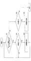
ここで、図4を参照し、コントローラ30がキャパシタ19のSOCに基づいて充電要求値及び放電要求値を導き出す処理(以下、「要求値導出処理」とする。)について説明する。なお、図4は、要求値導出処理の流れを示すフローチャートであり、コントローラ30は、所定の制御周期で繰り返しこの要求値導出処理を実行する。
Here, a process in which the controller 30 derives the charge request value and the discharge request value based on the SOC of the capacitor 19 (hereinafter referred to as “request value derivation process”) will be described with reference to FIG. FIG. 4 is a flowchart showing the flow of the required value derivation process, and the controller 30 repeatedly executes the required value derivation process at a predetermined control cycle.
最初に、コントローラ30は、キャパシタ19のSOCを取得する(ステップS1)。
First, the controller 30 acquires the SOC of the capacitor 19 (step S1).
また、コントローラ30は、旋回用電動機21の状態を検出する(ステップS2)。レゾルバ22の出力に基づいて算出される旋回速度から旋回用電動機21の運転状態と停止状態とを判別する。インバータ20を流れる電流に基づいて算出される旋回トルクと旋回速度から旋回用電動機21の力行運転状態と回生運転状態とを判別する。
Further, the controller 30 detects the state of the turning electric motor 21 (step S2). From the turning speed calculated based on the output of the resolver 22, the operating state and the stopped state of the turning electric motor 21 are determined. The power running operation state and the regenerative operation state of the turning electric motor 21 are discriminated from the turning torque and the turning speed calculated based on the current flowing through the inverter 20.
また、ステップS1及びステップS2は順不同であり、コントローラ30は、旋回用電動機21の状態を検出した後でキャパシタ19のSOCを取得してもよく、2つの処理を同時に実行してもよい。
Further, Step S1 and Step S2 are in no particular order, and the controller 30 may acquire the SOC of the capacitor 19 after detecting the state of the turning electric motor 21 or may execute two processes simultaneously.
その後、コントローラ30は、キャパシタ19のSOC及び旋回用電動機21の状態に基づいて充電要求値を導き出す(ステップS3)。このとき、内部メモリに格納されたSOC・要求値対応テーブルを参照してもよい。
Thereafter, the controller 30 derives a charge request value based on the SOC of the capacitor 19 and the state of the turning electric motor 21 (step S3). At this time, the SOC / request value correspondence table stored in the internal memory may be referred to.
また、キャパシタ19のSOC及び旋回用電動機21の状態に基づいて放電要求値を導き出す(ステップS4)。本実施例では、コントローラ30は、充電要求値を導出する場合に用いたSOC・要求値対応テーブルを参照してもよい。
Also, a required discharge value is derived based on the SOC of the capacitor 19 and the state of the turning electric motor 21 (step S4). In the present embodiment, the controller 30 may refer to the SOC / requested value correspondence table used when deriving the charge request value.
図5は、SOC・要求値対応テーブルの一例を説明する図である。図5は、キャパシタ19のSOCと放電要求値及び充電要求値との関係を示すグラフであり、横軸がSOC[%]に対応し、縦軸が要求値に対応する。なお、図5では、放電要求値を正値とし、充電要求値を負値とする。また、図5の充電要求値は、キャパシタ19の充電のために電動発電機12を発電機として機能させるためのものである。旋回用電動機21の回生電力は、充電要求値に応じた電動発電機12の発電電力による充電とは別にキャパシタ19に充電される。
FIG. 5 is a diagram for explaining an example of the SOC / required value correspondence table. FIG. 5 is a graph showing the relationship between the SOC of the capacitor 19, the required discharge value, and the required charge value. The horizontal axis corresponds to SOC [%], and the vertical axis corresponds to the required value. In FIG. 5, the required discharge value is a positive value and the required charge value is a negative value. The charge request value in FIG. 5 is for causing the motor generator 12 to function as a generator for charging the capacitor 19. The regenerative electric power of the turning electric motor 21 is charged in the capacitor 19 separately from the charging by the electric power generated by the motor generator 12 according to the charging request value.
図5の破線で示す充電要求線CL1は、旋回用電動機21が力行運転状態の場合に採用される充電要求値の推移を表す。また、SOCが40[%]以下の場合に充電要求値が値C1となり、さらにSOCが低下しても値C1で一定である。SOCが40[%]を超えて45[%]に至るまで徐々に値ゼロに近づき、SOCが45[%]以上の場合に値ゼロ(ゼロ付近を含む。以下同じ。)となることを表す。充電要求線CL1が採用された場合、SOCは、40[%]以下のときには40[%]を超えるときに比べて増大され易い。したがって、SOCが相対的に低い場合から充電率が増加し、40~45[%]の間で維持され易い。また、SOCがさらに低下しても値C1が比較的低めに設定されるため、発電量を低めに抑え、エンジン出力が油圧負荷、旋回負荷に振り向けられ易くする。
The charge request line CL1 indicated by a broken line in FIG. 5 represents a transition of the charge request value employed when the turning electric motor 21 is in the power running operation state. Further, when the SOC is 40 [%] or less, the charge request value becomes the value C1, and even when the SOC further decreases, the value C1 is constant. The value gradually approaches zero until the SOC exceeds 40 [%] and reaches 45 [%]. When the SOC is 45 [%] or more, the value becomes zero (including the vicinity of zero; the same applies hereinafter). . When the charge request line CL1 is employed, the SOC is more likely to be increased when it is 40 [%] or less than when it exceeds 40 [%]. Therefore, the charging rate increases from when the SOC is relatively low, and is easily maintained between 40% and 45%. Further, even if the SOC further decreases, the value C1 is set relatively low, so that the amount of power generation is kept low and the engine output is easily directed to the hydraulic load and the turning load.
また、図5の一点鎖線で示す充電要求線CL2は、旋回用電動機21が回生運転状態の場合に採用される充電要求値の推移を表す。また、SOCが40[%]以下の場合に充電要求値が値C2となり、さらにSOCが低下しても値C2で一定である。SOCが40[%]を超えて60[%]に至るまで徐々に値ゼロに近づき、SOCが60[%]以上の場合に値ゼロとなることを表す。充電要求線CL2が採用された場合、SOCは、40[%]以下のときには40[%]を超えるときに比べて増大され易い。また、SOCは45~60[%]付近で維持され易い。また、SOCがさらに低下しても値C2が比較的低めに設定されるため、発電量を低めに抑え、エンジン出力が油圧負荷、旋回負荷に振り向けられ易くする。値C1より値C2の場合のほうが充電され易いが、これは旋回が回生中であるため旋回負荷への発電量をあまり考慮しなくてもよいからである。
Further, a charging request line CL2 indicated by a one-dot chain line in FIG. 5 represents a transition of a charging request value adopted when the turning electric motor 21 is in a regenerative operation state. Further, when the SOC is 40 [%] or less, the charge request value becomes the value C2, and even if the SOC further decreases, the value C2 is constant. It represents that the value gradually approaches zero until the SOC exceeds 40 [%] and reaches 60 [%], and the value becomes zero when the SOC is 60 [%] or more. When the charge request line CL2 is employed, the SOC is more likely to be increased when it is 40 [%] or less than when it exceeds 40 [%]. Also, the SOC is easily maintained in the vicinity of 45 to 60 [%]. Further, even if the SOC further decreases, the value C2 is set to be relatively low, so that the amount of power generation is kept low and the engine output is easily directed to the hydraulic load and the turning load. The value C2 is more easily charged than the value C1, because the power generation amount to the turning load does not need to be considered much because the turning is being regenerated.
また、図5の二点鎖線で示す充電要求線CL3は、旋回用電動機21が停止状態の場合に採用される充電要求値の推移を表す。また、SOCが40[%]以下の場合に充電要求値が値C3となり、SOCが40[%]を超えて60[%]に至るまで徐々に値ゼロに近づき、SOCが60[%]以上の場合に値ゼロとなることを表す。充電要求線CL3が採用された場合、SOCは、40[%]以下のときには40[%]を超えるときに比べて増大され易い。したがって、45~60[%]の間で維持され易い。また、SOCがさらに低下しても値C3が比較的低めに設定されるため、発電量を低めに抑え、エンジン出力が油圧負荷、旋回負荷に振り向けられ易くする。値C3のレベルは値C2より低く、値C1より大きい。これは旋回停止中であることを考慮したものである。
Further, a charging request line CL3 indicated by a two-dot chain line in FIG. 5 represents a transition of a charging request value adopted when the turning electric motor 21 is stopped. Further, when the SOC is 40 [%] or less, the charge request value becomes the value C3, gradually approaches the value zero until the SOC exceeds 40 [%] and reaches 60 [%], and the SOC is 60 [%] or more. Indicates that the value is zero. When the charge request line CL3 is employed, the SOC is more likely to be increased when it is 40 [%] or less than when it exceeds 40 [%]. Therefore, it is easily maintained between 45 and 60 [%]. Further, even if the SOC further decreases, the value C3 is set relatively low, so that the amount of power generation is kept low, and the engine output is easily directed to the hydraulic load and the turning load. The level of the value C3 is lower than the value C2 and higher than the value C1. This is because the turning is stopped.
また、図5の破線で示す放電要求線DL1は、旋回用電動機21が力行運転状態の場合に採用される放電要求値の推移を表す。また、SOCが60[%]以下の場合に放電要求値が値ゼロとなり、SOCが60[%]を超えて100[%]に至るまで一定の割合で増加し、SOCが100[%]に達した場合に値D1となることを表す。放電要求線DL1が採用された場合、SOCは高いレベルのときほど多く放電することができ電動機(例えば旋回)の駆動力を大きくできる。その分、SOCは低減され易く、60[%]付近で維持され易い。
Further, a discharge request line DL1 indicated by a broken line in FIG. 5 represents a transition of a discharge request value adopted when the turning electric motor 21 is in a power running operation state. Further, when the SOC is 60 [%] or less, the required discharge value becomes zero, the SOC increases at a constant rate from 60 [%] to 100 [%], and the SOC reaches 100 [%]. When it reaches, it represents that the value becomes D1. When the discharge request line DL1 is employed, the SOC can be discharged as the level becomes higher, and the driving force of the electric motor (for example, turning) can be increased. Accordingly, the SOC is easily reduced and is easily maintained in the vicinity of 60 [%].
また、図5の一点鎖線で示す放電要求線DL2は、旋回用電動機21が回生運転状態の場合に採用される放電要求値の推移を表す。また、SOCが70[%]以下の場合に放電要求値が値ゼロとなり、SOCが70[%]を超えて80[%]に至るまで一定の割合で増加し、SOCが80[%]以上の場合に値D2となることを表す。放電要求線DL2が採用された場合、SOCは、80[%]以上のときには80[%]未満のときに比べて多く放電することができ電動機(例えばアシスト)の駆動力を大きくできる。その分、SOCは低減され易く、70~80[%]の間、特に70[%]付近で維持され易い。
Further, the discharge request line DL2 indicated by a one-dot chain line in FIG. 5 represents a transition of the discharge request value employed when the turning electric motor 21 is in the regenerative operation state. Further, when the SOC is 70 [%] or less, the required discharge value becomes zero, the SOC increases at a constant rate from 70 [%] to 80 [%], and the SOC is 80 [%] or more. In this case, the value D2 is represented. When the discharge request line DL2 is adopted, the SOC can be discharged more when it is 80 [%] or more than when it is less than 80 [%], and the driving force of the electric motor (for example, assist) can be increased. Accordingly, the SOC is easily reduced, and is easily maintained between 70 and 80 [%], particularly in the vicinity of 70 [%].
また、図5の二点鎖線で示す放電要求線DL3は、旋回用電動機21が停止状態の場合に採用される放電要求値の推移を表す。また、SOCが70[%]以下の場合に放電要求値が値ゼロとなり、SOCが70[%]を超えて85[%]に至るまで一定の割合で増加し、SOCが85[%]以上の場合に値D3となることを表す。放電要求線DL3が採用された場合、SOCは、85[%]以上のときには85[%]未満のときに比べて電動機の駆動力を大きくできるがその分SOCは低減され易い。したがって、70~85[%]の間、特に70[%]付近で維持され易い。
Further, a discharge request line DL3 indicated by a two-dot chain line in FIG. 5 represents a transition of the discharge request value that is adopted when the turning electric motor 21 is in a stopped state. Further, when the SOC is 70 [%] or less, the required discharge value becomes zero, the SOC increases at a constant rate from 70 [%] to 85 [%], and the SOC is 85 [%] or more. In this case, the value D3 is represented. When the discharge request line DL3 is employed, the SOC can be increased when the SOC is 85 [%] or more compared to when the SOC is less than 85 [%], but the SOC is easily reduced accordingly. Therefore, it is easily maintained between 70 and 85 [%], particularly in the vicinity of 70 [%].
図5のグラフは、キャパシタ19の現在のSOCが70[%]で且つ旋回用電動機21の現在の状態が力行運転状態であれば、充電要求値が値ゼロで且つ放電要求値がD4であることを表す。キャパシタ19の現在のSOCが30[%]で且つ旋回用電動機21の現在の状態が回生運転状態であれば、充電要求値がC2で且つ放電要求値が値ゼロであることを表す。このように、電動発電機12の発電及び旋回回生によるキャパシタ19の充電と、電動発電機12のアシスト及び旋回力行のためのキャパシタ19の放電とは、特定の放電要求線と充電要求線に基本的にしたがって実行される。放電に関してはSOCが大きいほど放電し易く、充電に関してはSOCが小さいほど充電され易い領域とSOCが小さくても一定の充電要求値とされている領域が設けられている。このように設定することにより、蓄電系120は放電により駆動力を出し易く、発電によりエンジン11の負荷の増大を抑えるようにされており、作業性が高い形態となっている。
The graph of FIG. 5 shows that when the current SOC of the capacitor 19 is 70 [%] and the current state of the turning electric motor 21 is a power running state, the charge request value is zero and the discharge request value is D4. Represents that. If the current SOC of the capacitor 19 is 30 [%] and the current state of the turning electric motor 21 is in the regenerative operation state, this indicates that the charge request value is C2 and the discharge request value is zero. Thus, the charging of the capacitor 19 by the power generation and turning regeneration of the motor generator 12 and the discharging of the capacitor 19 for assisting and turning the motor generator 12 are based on a specific discharge request line and a charge request line. Therefore, it is executed accordingly. As for discharging, the larger the SOC is, the easier it is to discharge, and as for charging, there are a region where charging is easier as the SOC is smaller and a region where a constant required charging value is provided even if the SOC is smaller. By setting in this way, the power storage system 120 can easily generate a driving force by discharging, suppresses an increase in the load of the engine 11 by power generation, and has a high workability.
次に、図6を参照し、旋回用電動機21が力行運転状態の場合に、コントローラ30が充電要求値及び放電要求値を利用してキャパシタ19の充放電を制御する処理(以下、「旋回力行時処理」とする。)について説明する。
Next, referring to FIG. 6, when the turning electric motor 21 is in the power running state, the controller 30 controls charging / discharging of the capacitor 19 using the charge request value and the discharge request value (hereinafter referred to as “turning power running”). "Time processing") will be described.
最初に、コントローラ30は、旋回用電動機21の旋回駆動に必要な出力(以下、「所要出力」とする。)が放電要求値以下であるか否かを判定する(ステップS11)。放電電力のみで旋回用電動機21を駆動できるか判断するためである。コントローラ30は、レゾルバ22の出力に基づいて算出される旋回速度と、インバータ20を流れる電流に基づいて算出される旋回トルクの積から所要出力を導き出す。そして、コントローラ30は、その所要出力と図4の要求値導出処理で導き出した放電要求値とを比較する。
First, the controller 30 determines whether or not an output (hereinafter referred to as “required output”) required for the turning drive of the turning electric motor 21 is equal to or less than a discharge request value (step S11). This is for determining whether or not the turning electric motor 21 can be driven only by the discharge power. The controller 30 derives a required output from the product of the turning speed calculated based on the output of the resolver 22 and the turning torque calculated based on the current flowing through the inverter 20. Then, the controller 30 compares the required output with the required discharge value derived by the required value derivation process of FIG.
所要出力が放電要求値以下であると判定した場合(ステップS11のYES)、コントローラ30は、キャパシタ19が放電する電力(放電電力)のみで旋回用電動機21を駆動させる(ステップS12)。
When it is determined that the required output is equal to or less than the required discharge value (YES in step S11), the controller 30 drives the turning electric motor 21 only with the electric power (discharge power) discharged from the capacitor 19 (step S12).
一方、所要出力が放電要求値より大きいと判定した場合(ステップS11のNO)、コントローラ30は、充電要求値が値ゼロであるか否かを判定する(ステップS13)。値ゼロの充電要求値は、用いられた充電要求線に基づいてSOCが所定値以上となっている場合に、これ以上充電しないように制御するために採用されることがある。この場合、キャパシタ19の充電が停止される。充電要求値がゼロでない場合は、発電電力の一部が充電に当てられる。
On the other hand, when it is determined that the required output is greater than the required discharge value (NO in step S11), the controller 30 determines whether the required charge value is zero (step S13). A charge request value of zero may be adopted to control so that no further charging is performed when the SOC is greater than or equal to a predetermined value based on the charge request line used. In this case, charging of the capacitor 19 is stopped. When the charge request value is not zero, a part of the generated power is used for charging.
充電要求値が値ゼロであると判定した場合(ステップS13のYES)、コントローラ30は、所要出力が放電要求値と発電制限値の合計以下であるか否かを判定する(ステップS14)。放電電力と発電電力のみで旋回用電動機21を駆動できるか判断するためである。なお、発電制限値は、電動発電機12が発電可能な電力の最大値を意味する。
When it is determined that the charge request value is zero (YES in step S13), the controller 30 determines whether the required output is equal to or less than the sum of the discharge request value and the power generation limit value (step S14). This is to determine whether or not the turning electric motor 21 can be driven only by the discharged power and the generated power. The power generation limit value means the maximum value of electric power that can be generated by the motor generator 12.
所要出力が放電要求値と発電制限値の合計以下であると判定した場合(ステップS14のYES)、コントローラ30は、放電要求値が値ゼロであるか否かを判定する(ステップS15)。値ゼロの放電要求値は、用いられた放電要求線に基づいてSOCが所定値以下となっている場合に、これ以上放電しないように制御するために採用されることがある。
When it is determined that the required output is less than or equal to the sum of the required discharge value and the power generation limit value (YES in step S14), the controller 30 determines whether the required discharge value is zero (step S15). A discharge request value of zero may be adopted to control so that no further discharge occurs when the SOC is below a predetermined value based on the used discharge request line.
放電要求値が値ゼロであると判定した場合(ステップS15のYES)、コントローラ30は、電動発電機12が発電する電力(発電電力)のみで旋回用電動機21を駆動させる(ステップS16)。
When it is determined that the required discharge value is zero (YES in step S15), the controller 30 drives the turning electric motor 21 only with electric power (generated electric power) generated by the motor generator 12 (step S16).
また、放電要求値が値ゼロでないと判定した場合(ステップS15のNO)、コントローラ30は、キャパシタ19が放電する放電電力と電動発電機12が発電する発電電力で旋回用電動機21を駆動させる(ステップS17)。
When it is determined that the required discharge value is not zero (NO in step S15), the controller 30 drives the turning electric motor 21 with the discharge electric power discharged from the capacitor 19 and the electric power generated by the motor generator 12 ( Step S17).
また、所要出力が放電要求値と発電制限値の合計より大きいと判定した場合(ステップS14のNO)、コントローラ30は、キャパシタ19が放電する放電要求値相当の放電電力より大きい放電電力と、電動発電機12が発電する発電制限値相当の発電電力で旋回用電動機21を駆動させる(ステップS19)。発電制限値相当の発電電力と放電要求値相当の放電電力とでは旋回用電動機21が必要とする所要出力を供給できないためである。但し、旋回出力を抑制するように制御してもよい。キャパシタ19からの放電を放電要求値相当に抑えることができる。
If it is determined that the required output is greater than the sum of the required discharge value and the power generation limit value (NO in step S14), the controller 30 is operated with a discharge power greater than the discharge power corresponding to the required discharge value discharged by the capacitor 19, and The turning electric motor 21 is driven with the generated electric power corresponding to the electric power generation limit value generated by the electric generator 12 (step S19). This is because the required output required by the turning electric motor 21 cannot be supplied with the generated power corresponding to the power generation limit value and the discharge power corresponding to the required discharge value. However, you may control so that turning output may be suppressed. The discharge from the capacitor 19 can be suppressed to a value equivalent to the required discharge value.
また、充電要求値が値ゼロでないと判定した場合(ステップS13のNO)、コントローラ30は、所要出力が発電制限値から充電要求値を差し引いた値以上であるか否かを判定する(ステップS18)。電動発電機12だけでは旋回用電動機21が必要とする所要出力を供給できないかを判断するためである。
If it is determined that the charge request value is not zero (NO in step S13), the controller 30 determines whether the required output is equal to or greater than the value obtained by subtracting the charge request value from the power generation limit value (step S18). ). This is for determining whether the required output required by the turning electric motor 21 cannot be supplied by the motor generator 12 alone.
所要出力が発電制限値から充電要求値を差し引いた値以上であると判定した場合(ステップS18のYES)、コントローラ30は、キャパシタ19が放電する放電要求値相当の放電電力より大きい放電電力と、電動発電機12が発電する発電制限値相当の発電電力とで旋回用電動機21を駆動させる(ステップS19)。電動発電機12が発電する充電要求値相当の発電電力でキャパシタ19を充電させた場合、キャパシタ19は放電できず、電動発電機12だけでは旋回用電動機21が必要とする所要出力を供給できないためである。但し、旋回出力を抑制するように制御してもよい。キャパシタ19からの放電を放電要求値相当に抑えることができる。
When it is determined that the required output is equal to or greater than the value obtained by subtracting the charge request value from the power generation limit value (YES in step S18), the controller 30 has a discharge power greater than the discharge power corresponding to the discharge request value discharged by the capacitor 19, The turning electric motor 21 is driven with the generated electric power corresponding to the electric power generation limit value generated by the motor generator 12 (step S19). When the capacitor 19 is charged with the generated power corresponding to the charge request value generated by the motor generator 12, the capacitor 19 cannot be discharged, and the motor generator 12 alone cannot supply the required output required for the turning motor 21. It is. However, you may control so that turning output may be suppressed. The discharge from the capacitor 19 can be suppressed to a value equivalent to the required discharge value.
一方、所要出力が発電制限値から充電要求値を差し引いた値未満であると判定した場合(ステップS18のNO)、コントローラ30は、電動発電機12が発電する発電電力のみで旋回用電動機21を駆動させ、且つ、電動発電機12が発電する充電要求値相当の発電電力でキャパシタ19を充電させる(ステップS20)。すなわち、電動発電機12は、所要出力に相当する電力の発電、及び、充電要求値に相当する電力の発電を行う。
On the other hand, when it is determined that the required output is less than the value obtained by subtracting the charge request value from the power generation limit value (NO in step S18), the controller 30 uses the generated power generated by the motor generator 12 only to turn the turning motor 21. The capacitor 19 is charged with the generated power corresponding to the charge request value generated by the motor generator 12 (step S20). That is, the motor generator 12 generates power corresponding to the required output and generates power corresponding to the charge request value.
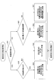
次に、図7を参照し、旋回用電動機21が回生運転状態の場合に、コントローラ30が充電要求値及び放電要求値を利用してキャパシタ19の充放電を制御する処理(以下、「旋回回生時処理」とする。)について説明する。
Next, referring to FIG. 7, when the turning electric motor 21 is in a regenerative operation state, the controller 30 uses the charge request value and the discharge request value to control charging / discharging of the capacitor 19 (hereinafter referred to as “turning regeneration”). "Time processing") will be described.
最初に、コントローラ30は、放電要求値が値ゼロであるか否かを判定する(ステップS21)。
First, the controller 30 determines whether or not the discharge request value is zero (step S21).
放電要求値が値ゼロであると判定した場合(ステップS21のYES)、すなわち、キャパシタ19の放電を停止している場合、コントローラ30は、充電要求値が値ゼロでないか否かを判定する(ステップS22)。キャパシタ19の充電を停止していないかを判断するためである。
When it is determined that the required discharge value is zero (YES in step S21), that is, when the discharge of the capacitor 19 is stopped, the controller 30 determines whether or not the required charge value is not zero ( Step S22). This is to determine whether charging of the capacitor 19 is stopped.
充電要求値が値ゼロでないと判定した場合(ステップS22のYES)、コントローラ30は、旋回用電動機21が回生する回生電力の全てと充電要求値に相当する発電電力をキャパシタ19に充電させる(ステップS23)。
If it is determined that the charge request value is not zero (YES in step S22), the controller 30 charges the capacitor 19 with all the regenerative power regenerated by the turning motor 21 and the generated power corresponding to the charge request value (step S22). S23).
なお、充電要求値が値ゼロであると判定した場合(ステップS22のNO)、発電電力はなく、コントローラ30は、旋回用電動機21が回生する回生電力の全てをキャパシタ19に充電させる(ステップS24)。
When it is determined that the charge request value is zero (NO in step S22), there is no generated power, and the controller 30 charges the capacitor 19 with all the regenerative power regenerated by the turning motor 21 (step S24). ).
また、放電要求値が値ゼロでないと判定した場合(ステップS21のNO)、コントローラ30は、回生電力が放電要求値より大きいか否かを判定する(ステップS25)。キャパシタ19の充電を行うかを判断するためである。なお、本実施例では、回生電力は負値で表され、放電要求値は正値で表される。そのため、厳密には、コントローラ30は、回生電力の絶対値が放電要求値より大きいか否かを判定する。
If it is determined that the required discharge value is not zero (NO in step S21), the controller 30 determines whether or not the regenerative power is greater than the required discharge value (step S25). This is to determine whether to charge the capacitor 19. In the present embodiment, the regenerative power is represented by a negative value, and the required discharge value is represented by a positive value. Therefore, strictly speaking, the controller 30 determines whether or not the absolute value of the regenerative power is larger than the required discharge value.
回生電力が放電要求値より大きいと判断した場合(ステップS25のYES)、コントローラ30は、回生電力と放電要求値に相当する電力の差の分だけ、キャパシタ19に充電させる(ステップS26)。本実施例では、コントローラ30は、放電要求値に相当する回生電力の一部を旋回用電動機21から電動発電機12に供給して電動発電機12を電動機として機能させ、回生電力の残りの部分をキャパシタ19に充電させる。
If it is determined that the regenerative power is greater than the required discharge value (YES in step S25), the controller 30 charges the capacitor 19 by the difference between the regenerative power and the required power value (step S26). In the present embodiment, the controller 30 supplies a part of the regenerative power corresponding to the required discharge value from the turning motor 21 to the motor generator 12 to cause the motor generator 12 to function as the motor, and the remaining part of the regenerative power. Is charged in the capacitor 19.
一方、回生電力が放電要求値以下であると判断した場合(ステップS25のNO)、コントローラ30は、回生電力と放電要求値に相当する電力との和を電動発電機12に向かわせる(ステップS27)。本実施例では、コントローラ30は、回生電力の全てを旋回用電動機21から電動発電機12に供給し、且つ、放電要求値に相当する電力をキャパシタ19から電動発電機12に供給して電動発電機12を電動機として機能させる。
On the other hand, when it is determined that the regenerative power is equal to or less than the required discharge value (NO in step S25), the controller 30 directs the sum of the regenerative power and the power corresponding to the required discharge value to the motor generator 12 (step S27). ). In the present embodiment, the controller 30 supplies all of the regenerative power from the turning motor 21 to the motor generator 12, and supplies power corresponding to the discharge required value from the capacitor 19 to the motor generator 12. The machine 12 is caused to function as an electric motor.
なお、本実施例では、電動機として機能する電動発電機12が受け入れ可能な電力は、所定のアシスト制限値によって制限される。この場合、アシスト制限値は、電動機として機能する電動発電機12が受け入れ可能な電力の最大値を意味する。アシスト出力が大きくなり過ぎてエンジン11が吹き上がってしまうのを防止するためである。したがって、回生電力と放電要求値に相当する電力との和がアシスト制限値に相当する電力を上回る場合、コントローラ30は、放電要求値に相当する電力を低減させることで、すなわちキャパシタ19から放電される電力を低減させることで電動発電機12に供給される電力がアシスト制限値に相当する電力と等しくなるようにする。
In this embodiment, the electric power that can be accepted by the motor generator 12 that functions as an electric motor is limited by a predetermined assist limit value. In this case, the assist limit value means the maximum value of electric power that can be accepted by the motor generator 12 functioning as an electric motor. This is to prevent the assist output from becoming too large and the engine 11 from blowing up. Therefore, when the sum of the regenerative power and the power corresponding to the discharge request value exceeds the power corresponding to the assist limit value, the controller 30 is discharged from the capacitor 19 by reducing the power corresponding to the discharge request value. The electric power supplied to the motor generator 12 is made equal to the electric power corresponding to the assist limit value.
上述の旋回回生時処理を繰り返し実行することにより、コントローラ30は、図5の充電要求線CL2で示すように、値ゼロの放電要求値に対応するSOC(例えば30%)をキャパシタ19が示す場合、回生電力の全てをキャパシタ19に供給してキャパシタ19を充電させ、且つ、充電要求値に相当する電力を電動発電機12で発電させ、その発電電力でキャパシタ19を充電させる。このようにして、コントローラ30は、キャパシタ19のSOCが低い状態にある場合には、旋回回生時であっても電動発電機12に発電させてキャパシタ19を充電させることで、SOCを高い状態に戻す。
By repeatedly executing the above-described turning regeneration processing, the controller 30 causes the capacitor 19 to indicate the SOC (for example, 30%) corresponding to the discharge request value of zero as indicated by the charge request line CL2 of FIG. Then, all of the regenerative power is supplied to the capacitor 19 to charge the capacitor 19, and the electric power corresponding to the charge request value is generated by the motor generator 12, and the capacitor 19 is charged with the generated power. In this way, when the SOC of the capacitor 19 is in a low state, the controller 30 causes the motor generator 12 to generate power and charge the capacitor 19 even during turning regeneration, thereby increasing the SOC. return.
また、コントローラ30は、図5の放電要求線DL2で示すように、キャパシタ19の過充電を防止する。例えば、値ゼロでない放電要求値に対応するSOC(例えば70%より大きい値)をキャパシタ19が示す場合、回生電力の大きさが放電要求値の大きさより大きければ、その差分電力でキャパシタ19を充電させる。そして、放電要求値に相当する電力を旋回用電動機21から電動発電機12に供給して電動発電機12を電動機として機能させる。このようにして、コントローラ30は、180度旋回等で大きな回生電力が発生する場合であっても、その回生電力の一部を電動発電機12で消費させることで、キャパシタ19の過充電を防止する。
Further, the controller 30 prevents the capacitor 19 from being overcharged as indicated by a discharge request line DL2 in FIG. For example, when the capacitor 19 indicates an SOC (for example, a value greater than 70%) corresponding to a discharge request value that is not zero, if the regenerative power is greater than the discharge request value, the capacitor 19 is charged with the differential power. Let Then, electric power corresponding to the required discharge value is supplied from the turning electric motor 21 to the motor generator 12 to cause the motor generator 12 to function as an electric motor. In this way, the controller 30 prevents overcharging of the capacitor 19 by consuming a part of the regenerative power by the motor generator 12 even when large regenerative power is generated by turning 180 degrees or the like. To do.
また、値ゼロでない放電要求値に対応するSOC(例えば70%より大きい値)をキャパシタ19が示す場合、回生電力の大きさが放電要求値の大きさ以下であれば、コントローラ30は電動発電機12を電動機として機能させる。例えば、値ゼロの放電要求値に対応するSOC(例えば70%)に達するまでは、回生電力と放電要求値に相当する電力との和を電動発電機12に向かわせ、電動発電機12を電動機として機能させる。このようにして、コントローラ30は、キャパシタ19の過充電を防止する。
Further, when the capacitor 19 indicates an SOC (for example, a value greater than 70%) corresponding to a discharge request value that is not zero, if the regenerative power is equal to or smaller than the discharge request value, the controller 30 12 is made to function as an electric motor. For example, the sum of the regenerative power and the power corresponding to the required discharge value is directed to the motor generator 12 until the SOC (for example, 70%) corresponding to the discharge required value of zero is reached, and the motor generator 12 is moved to the motor. To function as. In this way, the controller 30 prevents the capacitor 19 from being overcharged.
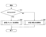
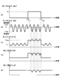
次に、図8を参照し、旋回用電動機21が停止状態の場合に、コントローラ30が充電要求値及び放電要求値を利用してキャパシタ19の充放電を制御する処理(以下、「旋回停止時処理」とする。)について説明する。なお、図8は、旋回停止時処理の流れを示すフローチャートであり、コントローラ30は、旋回用電動機21が停止状態の場合に、所定の制御周期で繰り返しこの旋回停止時処理を実行する。
Next, referring to FIG. 8, when the turning electric motor 21 is in a stopped state, the controller 30 controls charging / discharging of the capacitor 19 using the charge request value and the discharge request value (hereinafter referred to as “when turning is stopped”). Process ”) will be described. FIG. 8 is a flowchart showing the flow of the turning stop process, and the controller 30 repeatedly executes the turning stop process at a predetermined control cycle when the turning electric motor 21 is stopped.
最初に、コントローラ30は、放電要求値が値ゼロであるか否かを判定する(ステップS31)。キャパシタ19の放電を停止しているかを判断するためである。
First, the controller 30 determines whether or not the discharge request value is zero (step S31). This is to determine whether or not the discharge of the capacitor 19 is stopped.
放電要求値が値ゼロであると判定した場合(ステップS31のYES)、すなわち、キャパシタ19の放電を停止している場合、コントローラ30は、充電要求値が値ゼロでないか否かを判定する(ステップS32)。キャパシタ19の充電を停止していないかを判断するためである。
When it is determined that the required discharge value is zero (YES in step S31), that is, when discharging of the capacitor 19 is stopped, the controller 30 determines whether or not the required charge value is not zero ( Step S32). This is to determine whether charging of the capacitor 19 is stopped.
充電要求値が値ゼロでないと判定した場合(ステップS32のYES)、すなわち、キャパシタ19の充電を停止していない場合、コントローラ30は、電動発電機12を発電機として機能させ、電動発電機12が発電する発電電力でキャパシタ19を充電させる(ステップS33)。
When it is determined that the charge request value is not zero (YES in step S32), that is, when charging of the capacitor 19 is not stopped, the controller 30 causes the motor generator 12 to function as a generator, and the motor generator 12 The capacitor 19 is charged with the generated electric power generated by (step S33).
なお、充電要求値が値ゼロであると判定した場合(ステップS32のNO)、すなわち、キャパシタ19の充電を停止している場合、コントローラ30は、キャパシタ19を充電させない。そのため、キャパシタ19の充電のみのために電動発電機12を発電機として機能させることはない。但し、他の目的のために電動発電機12を発電機として機能させることを禁止することはない。
If it is determined that the charge request value is zero (NO in step S32), that is, if charging of the capacitor 19 is stopped, the controller 30 does not charge the capacitor 19. Therefore, the motor generator 12 is not allowed to function as a generator only for charging the capacitor 19. However, it does not prohibit the motor generator 12 from functioning as a generator for other purposes.
一方、放電要求値が値ゼロでないと判定した場合(ステップS31のNO)、すなわち、キャパシタ19の放電を停止していない場合、コントローラ30は、キャパシタ19が放電する電力で電動発電機12を駆動させる(ステップS34)。
On the other hand, when it is determined that the required discharge value is not zero (NO in step S31), that is, when the discharge of the capacitor 19 is not stopped, the controller 30 drives the motor generator 12 with the electric power discharged from the capacitor 19. (Step S34).
上述の旋回停止時処理を繰り返し実行することにより、コントローラ30は、図5の充電要求線CL3で示すように、キャパシタ19の過放電を防止する。例えば、値ゼロでない充電要求値に対応するSOC(例えば30%)を示すキャパシタ19を、値ゼロの充電要求値に対応するSOC(例えば60%)まで充電させる。このようにして、コントローラ30は、所定の場合には、旋回停止時であってもキャパシタ19を充電させることで、キャパシタ19の過放電を防止する。所定の場合は、例えば、エンジン11の負荷を一定にすべく電動発電機12を電動機として機能させるためのキャパシタ19の放電が増えてキャパシタ19のSOCが低い状態にある場合を含む。
By repeatedly executing the above-described turning stop process, the controller 30 prevents the capacitor 19 from being overdischarged, as indicated by the charge request line CL3 in FIG. For example, the capacitor 19 indicating the SOC (for example, 30%) corresponding to the charge request value that is not zero is charged to the SOC (for example, 60%) corresponding to the zero charge request value. In this way, the controller 30 prevents the capacitor 19 from being overdischarged by charging the capacitor 19 even when turning is stopped in a predetermined case. The predetermined case includes, for example, a case where the discharge of the capacitor 19 for causing the motor generator 12 to function as an electric motor to increase the load of the engine 11 increases and the SOC of the capacitor 19 is low.
また、コントローラ30は、図5の放電要求線DL3で示すように、値ゼロでない放電要求値に対応するSOC(例えば90%)を示すキャパシタ19を、値ゼロの放電要求値に対応するSOC(例えば70%)まで放電させる。このようにして、コントローラ30は、キャパシタ19が頻繁に充電される場合であっても、キャパシタ19のSOCが過度に高くなるのを防止できる。キャパシタ19は、例えば、エンジン11に意図的に負荷を掛けるために電動発電機12を発電機として機能させる機会、又は、エンジン11の負荷を一定にすべく電動発電機12を電動機として機能させる機会が増えることで頻繁に充電される。
Further, as indicated by the discharge request line DL3 in FIG. 5, the controller 30 replaces the capacitor 19 indicating the SOC (for example, 90%) corresponding to the discharge request value that is not zero with the SOC ( For example, 70%). In this way, the controller 30 can prevent the SOC of the capacitor 19 from becoming excessively high even when the capacitor 19 is frequently charged. The capacitor 19 is, for example, an opportunity for the motor generator 12 to function as a generator to intentionally apply a load to the engine 11, or an opportunity for the motor generator 12 to function as an electric motor in order to keep the load on the engine 11 constant. The battery is charged more frequently as the number increases.
また、コントローラ30は、充電要求値及び放電要求値が何れも値ゼロとなるSOC(例えば60%以上70%以下)をキャパシタ19が示す場合、キャパシタ19を充放電させないようにする。
Further, the controller 30 prevents the capacitor 19 from being charged / discharged when the capacitor 19 indicates an SOC (for example, 60% or more and 70% or less) in which both the charge request value and the discharge request value are zero.
以上の構成により、コントローラ30は、キャパシタ19の現在のSOCに対応する充電要求値及び放電要求値に基づいてキャパシタ19の充放電を制御する。そのため、キャパシタ19の充放電をより適切に制御できる。
With the above configuration, the controller 30 controls charging / discharging of the capacitor 19 based on the charge request value and the discharge request value corresponding to the current SOC of the capacitor 19. Therefore, charging / discharging of the capacitor 19 can be controlled more appropriately.
また、コントローラ30は、旋回用電動機21の状態に応じて充電要求値及び放電要求値を変化させる。そのため、キャパシタ19の充放電をより適切に制御できる。
Further, the controller 30 changes the charge request value and the discharge request value according to the state of the turning electric motor 21. Therefore, charging / discharging of the capacitor 19 can be controlled more appropriately.
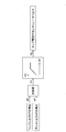
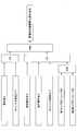
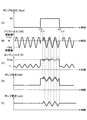
次に、図9を参照し、電動発電機12が発電機又は電動機として機能する場合に、コントローラ30がメインポンプ14のポンプ最大出力を増減させる処理(以下、「ポンプ最大出力増減処理」とする。)について説明する。なお、図9は、ポンプ最大出力増減処理を説明する概念図である。また、本実施例では、メインポンプ14の出力(吸収馬力)は、メインポンプ14の吐出量と吐出圧の積として算出される。
Next, referring to FIG. 9, when the motor generator 12 functions as a generator or a motor, the controller 30 increases or decreases the pump maximum output of the main pump 14 (hereinafter referred to as “pump maximum output increase / decrease process”). .). FIG. 9 is a conceptual diagram illustrating the pump maximum output increase / decrease process. In this embodiment, the output (absorption horsepower) of the main pump 14 is calculated as the product of the discharge amount and the discharge pressure of the main pump 14.
具体的には、コントローラ30は、エンジン出力EPを導き出す。本実施例では、コントローラ30は、エンジン回転数センサ(図示せず。)の検出値を受け、内部メモリに予め記憶されたエンジン回転数・エンジン出力対応マップを参照してエンジン出力EPを導き出す。
Specifically, the controller 30 derives the engine output EP. In this embodiment, the controller 30 receives a detection value of an engine speed sensor (not shown), and derives an engine output EP with reference to an engine speed / engine output correspondence map stored in advance in an internal memory.
また、コントローラ30は、アシスト出力APを導き出す。本実施例では、コントローラ30は、キャパシタ電圧検出部112及びキャパシタ電流検出部113の検出値に基づき、電動発電機12とキャパシタ19との間でやりとりされる電力をアシスト出力APとして導き出す。なお、本実施例では、アシスト出力APは、電動発電機12が電動機として機能する場合(キャパシタ19が放電を行う場合)に正値となり、電動発電機12が発電機として機能する場合(キャパシタ19が充電を行う場合)に負値となる。
Further, the controller 30 derives an assist output AP. In the present embodiment, the controller 30 derives the power exchanged between the motor generator 12 and the capacitor 19 as the assist output AP based on the detection values of the capacitor voltage detection unit 112 and the capacitor current detection unit 113. In the present embodiment, the assist output AP has a positive value when the motor generator 12 functions as a motor (when the capacitor 19 discharges), and when the motor generator 12 functions as a generator (the capacitor 19). Becomes negative when charging).
その後、コントローラ30は、エンジン出力EPとアシスト出力APとを加算して総出力TPを導き出す。総出力TPは、電動発電機12が電動機として機能する場合(キャパシタ19が放電を行う場合)にエンジン出力EPよりもアシスト出力AP分だけ大きい値となり、電動発電機12が発電機として機能する場合(キャパシタ19が充電を行う場合)にエンジン出力EPよりもアシスト出力AP分だけ小さい値となる。
Thereafter, the controller 30 adds the engine output EP and the assist output AP to derive the total output TP. When the motor generator 12 functions as a motor (when the capacitor 19 discharges), the total output TP becomes a value larger than the engine output EP by the assist output AP, and the motor generator 12 functions as a generator. When the capacitor 19 is charged, the value is smaller than the engine output EP by the assist output AP.
その後、コントローラ30は、ポンプ電流PCを導き出す。本実施例では、コントローラ30は、エンジン回転数センサの検出値を受け、内部メモリに予め記憶されているエンジン回転数に応じた総出力・ポンプ電流対応マップを参照してポンプ電流PCを導き出す。
Thereafter, the controller 30 derives the pump current PC. In this embodiment, the controller 30 receives the detection value of the engine speed sensor and derives the pump current PC by referring to the total output / pump current correspondence map corresponding to the engine speed stored in advance in the internal memory.
その後、コントローラ30は、ポンプ電流PCをメインポンプ14のレギュレータ(図示せず。)に対して出力する。なお、レギュレータは、コントローラ30からの指令に応じてメインポンプ14の斜板傾転角を調整してメインポンプ14の吐出量を制御する装置である。本実施例では、レギュレータは、ポンプ電流PCが小さいほどメインポンプ14の吐出量を低減させる。
Thereafter, the controller 30 outputs a pump current PC to a regulator (not shown) of the main pump 14. The regulator is a device that controls the discharge amount of the main pump 14 by adjusting the tilt angle of the swash plate of the main pump 14 in accordance with a command from the controller 30. In the present embodiment, the regulator reduces the discharge amount of the main pump 14 as the pump current PC is smaller.
そのため、コントローラ30は、エンジン出力EPが一定であれば、アシスト出力APが大きいほど、ポンプ電流PCを大きくしてメインポンプ14のポンプ最大出力を増大させる。すなわち、エンジン回転数が一定であれば、電動発電機12の電力消費量(キャパシタ19の放電量)が大きいほど、ポンプ電流PCを大きくしてメインポンプ14のポンプ最大出力を増大させることもできる。アシスト出力APが大きくなると総出力TPも大きくなり、総出力TPに余裕が生じるためであり、その余裕分をメインポンプ14が効率的に利用できるようにするためである。その結果、メインポンプ14の出力(吸収馬力)は、増大されたポンプ最大出力の範囲内で制御される。その一方で、エンジン11に急負荷が加わった場合にレギュレータを調整せずにアシスト力を増加させてメインポンプ14の負荷を吸収してもよい。
Therefore, if the engine output EP is constant, the controller 30 increases the pump current PC and increases the pump maximum output of the main pump 14 as the assist output AP increases. That is, if the engine speed is constant, the pump current PC can be increased and the pump maximum output of the main pump 14 can be increased as the power consumption of the motor generator 12 (discharge amount of the capacitor 19) is increased. . This is because when the assist output AP increases, the total output TP also increases and a margin is generated in the total output TP, so that the main pump 14 can efficiently use the margin. As a result, the output (absorption horsepower) of the main pump 14 is controlled within the range of the increased pump maximum output. On the other hand, when a sudden load is applied to the engine 11, the assist force may be increased without adjusting the regulator to absorb the load of the main pump 14.
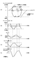
次に、図10を参照し、キャパシタ温度に応じてコントローラ30がSOC・要求値対応テーブルの内容を調整する処理について説明する。なお、ここではキャパシタ温度を採用するが、キャパシタ19に影響を与える環境又は機構等の温度であればよい。また、図10は、SOC・要求値対応テーブルの別の例を示す図であり、図5に対応する。具体的には、図10は、キャパシタ19のSOCと旋回用電動機21が力行運転状態の場合に採用される放電要求値及び充電要求値との関係を示すグラフであり、横軸がSOC[%]に対応し、縦軸が出力[kW]に対応する。
Next, a process in which the controller 30 adjusts the contents of the SOC / required value correspondence table according to the capacitor temperature will be described with reference to FIG. Here, the capacitor temperature is adopted, but any temperature or environment that affects the capacitor 19 may be used. FIG. 10 is a diagram showing another example of the SOC / required value correspondence table, which corresponds to FIG. Specifically, FIG. 10 is a graph showing a relationship between the SOC of the capacitor 19 and the required discharge value and the required charge value when the turning electric motor 21 is in a powering operation state, and the horizontal axis indicates the SOC [%. ], And the vertical axis corresponds to the output [kW].
また、図10の破線で示す放電要求線DL(20℃)は、旋回用電動機21が力行運転状態で且つキャパシタ温度が20℃の場合に採用される放電要求値の推移を表し、図5の放電要求線DL1に相当する。また、破線で示す放電要求線DL(0℃)はキャパシタ温度が0℃の場合に採用される放電要求値の推移を表す。同様に、破線で示す放電要求線DL(-10℃)はキャパシタ温度が-10℃の場合に採用される放電要求値の推移を表し、破線で示す放電要求線DL(-20℃)は、キャパシタ温度が-20℃の場合に採用される放電要求値の推移を表す。
Further, the discharge request line DL (20 ° C.) indicated by the broken line in FIG. 10 represents the transition of the discharge request value adopted when the turning electric motor 21 is in the power running state and the capacitor temperature is 20 ° C. This corresponds to the discharge request line DL1. Further, a discharge request line DL (0 ° C.) indicated by a broken line represents a transition of the discharge request value adopted when the capacitor temperature is 0 ° C. Similarly, a required discharge line DL (−10 ° C.) indicated by a broken line represents a change in required discharge value adopted when the capacitor temperature is −10 ° C., and a required discharge line DL (−20 ° C.) indicated by a broken line is It represents the transition of the required discharge value adopted when the capacitor temperature is −20 ° C.
また、図10の点線で示す充電要求線CL(20℃)は、旋回用電動機21が力行運転状態で且つキャパシタ温度が20℃の場合に採用される充電要求値の推移を表し、図5の充電要求線CL1に対応する。また、点線で示す充電要求線CL(0℃)はキャパシタ温度が0℃の場合に採用される充電要求値の推移を表す。同様に、点線で示す充電要求線CL(-10℃)はキャパシタ温度が-10℃の場合に採用される充電要求値の推移を表し、点線で示す充電要求線CL(-20℃)は、キャパシタ温度が-20℃の場合に採用される充電要求値の推移を表す。
Further, the charging request line CL (20 ° C.) indicated by the dotted line in FIG. 10 represents the transition of the charging request value adopted when the turning electric motor 21 is in the powering operation state and the capacitor temperature is 20 ° C. This corresponds to the charge request line CL1. Further, a charging request line CL (0 ° C.) indicated by a dotted line represents a transition of a charging request value adopted when the capacitor temperature is 0 ° C. Similarly, a charge request line CL (−10 ° C.) indicated by a dotted line represents a transition of a charge request value adopted when the capacitor temperature is −10 ° C., and a charge request line CL (−20 ° C.) indicated by a dotted line is It represents the transition of the required charging value adopted when the capacitor temperature is −20 ° C.
また、図10の実線で示す放電制限線UL(20℃)は、キャパシタ温度が20℃の場合の放電制限値の推移を表す。放電制限値は、キャパシタ19が放電可能な電力の最大値を意味し、キャパシタ19の過放電を防止するために用いられる。具体的には、キャパシタ19の端子電圧が所定の下限電圧を下回らないようにキャパシタ19の放電電力を制限する際に用いられる。図10ではSOCが30[%]の場合にキャパシタ19の放電電力が値D10で制限され、仮にキャパシタ19の放電電力が値D10を上回ると端子電圧が下限電圧を下回るおそれがあることを表す。また、実線で示す放電制限線UL(0℃)はキャパシタ温度が0℃の場合の放電制限値の推移を表す。同様に、実線で示す放電制限線UL(-10℃)は、キャパシタ温度が-10℃の場合の放電制限値の推移を表し、実線で示す放電制限線UL(-20℃)は、キャパシタ温度が-20℃の場合の放電制限値の推移を表す。
Also, the discharge limit line UL (20 ° C.) indicated by the solid line in FIG. 10 represents the transition of the discharge limit value when the capacitor temperature is 20 ° C. The discharge limit value means the maximum value of power that can be discharged by the capacitor 19 and is used to prevent the capacitor 19 from being overdischarged. Specifically, it is used when limiting the discharge power of the capacitor 19 so that the terminal voltage of the capacitor 19 does not fall below a predetermined lower limit voltage. In FIG. 10, when SOC is 30 [%], the discharge power of the capacitor 19 is limited by the value D10. If the discharge power of the capacitor 19 exceeds the value D10, the terminal voltage may fall below the lower limit voltage. A discharge limit line UL (0 ° C.) indicated by a solid line represents a transition of the discharge limit value when the capacitor temperature is 0 ° C. Similarly, the discharge limit line UL (−10 ° C.) indicated by the solid line represents the transition of the discharge limit value when the capacitor temperature is −10 ° C., and the discharge limit line UL (−20 ° C.) indicated by the solid line is the capacitor temperature. Represents the transition of the discharge limit value when -20 ° C.
また、図10の実線で示す充電制限線BL(20℃)は、キャパシタ温度が20℃の場合の充電制限値の推移を表す。充電制限値は、キャパシタ19が充電可能な電力の最大値を意味し、キャパシタ19の過充電を防止するために用いられる。具体的には、キャパシタ19の端子電圧が所定の上限電圧を上回らないようにキャパシタ19の充電電力を制限する際に用いられる。図10ではSOCが55[%]の場合にキャパシタ19の充電電力が値C10で制限され、仮にキャパシタ19の充電電力が値C10を上回ると端子電圧が上限電圧を上回るおそれがあることを表す。また、実線で示す充電制限線BL(0℃)はキャパシタ温度が0℃の場合の充電制限値の推移を表す。同様に、実線で示す充電制限線BL(-10℃)は、キャパシタ温度が-10℃の場合の充電制限値の推移を表し、実線で示す充電制限線BL(-20℃)は、キャパシタ温度が-20℃の場合の充電制限値の推移を表す。なお、以下では、充電制限値及び放電制限値を纏めて充放電制限値と称する場合もある。
In addition, a charging limit line BL (20 ° C.) indicated by a solid line in FIG. 10 represents a transition of the charging limit value when the capacitor temperature is 20 ° C. The charge limit value means a maximum value of power that can be charged by the capacitor 19 and is used to prevent the capacitor 19 from being overcharged. Specifically, it is used to limit the charging power of the capacitor 19 so that the terminal voltage of the capacitor 19 does not exceed a predetermined upper limit voltage. In FIG. 10, when the SOC is 55 [%], the charging power of the capacitor 19 is limited by the value C10. If the charging power of the capacitor 19 exceeds the value C10, the terminal voltage may exceed the upper limit voltage. A charging limit line BL (0 ° C.) indicated by a solid line represents a transition of the charging limit value when the capacitor temperature is 0 ° C. Similarly, the charging limit line BL (−10 ° C.) indicated by a solid line represents the transition of the charging limit value when the capacitor temperature is −10 ° C., and the charging limit line BL (−20 ° C.) indicated by the solid line is the capacitor temperature. Represents the transition of the charging limit value when -20 ° C. Hereinafter, the charge limit value and the discharge limit value may be collectively referred to as a charge / discharge limit value.
次に、キャパシタ温度に応じて採用すべき放電要求線を変更することの効果について説明する。
Next, the effect of changing the discharge request line to be adopted according to the capacitor temperature will be described.
図10の例では、放電要求線DL(20℃)は、SOCが60[%]以下の場合に値ゼロとなり、SOCが60[%]を超えて100[%]に至るまで変化率αで増加する。また、放電要求線DL(0℃)は、SOCが48[%]以下の場合に値ゼロとなり、SOCが48[%]を超えて100[%]に至るまで変化率αで増加する。また、放電要求線DL(-10℃)は、SOCが40[%]以下の場合に値ゼロとなり、SOCが40[%]を超えて放電制限線に至るまで変化率αで増加し、放電制限線UL(-10℃)のレベルに達した後は放電制限線UL(-10℃)に沿って増加する。また、放電要求線DL(-20℃)は、SOCが25[%]以下の場合に値ゼロとなり、SOCが25[%]を超えて100[%]に至るまで放電制限線UL(-20℃)に沿って増加する。なお、放電要求線DL(20℃)、放電要求線DL(0℃)、及び放電要求線DL(-10℃)のSOCに対する変化率αは、対応する放電制限線以下の領域で等しい。
In the example of FIG. 10, the discharge request line DL (20 ° C.) has a value of zero when the SOC is 60% or less, and has a change rate α until the SOC exceeds 60% and reaches 100%. To increase. Further, the discharge request line DL (0 ° C.) has a value of zero when the SOC is equal to or less than 48 [%], and increases at a change rate α until the SOC exceeds 48 [%] and reaches 100 [%]. The discharge request line DL (−10 ° C.) becomes zero when the SOC is 40% or less, and increases at a change rate α until the SOC exceeds 40% and reaches the discharge limit line. After reaching the level of the limit line UL (−10 ° C.), it increases along the discharge limit line UL (−10 ° C.). The discharge request line DL (−20 ° C.) is zero when the SOC is 25% or less, and the discharge limit line UL (−20 until the SOC exceeds 25% and reaches 100%. C). Note that the rate of change α with respect to the SOC of the discharge request line DL (20 ° C.), the discharge request line DL (0 ° C.), and the discharge request line DL (−10 ° C.) is equal in the region below the corresponding discharge limit line.
このように、キャパシタ温度が低下するにつれて、放電要求値が値ゼロより大きくなるときのSOC(放電開始充電率:放電開始SOC)を低くすることで、コントローラ30は、旋回用電動機21の力行運転及び回生運転が行われる際のSOCを低減させることができる。具体的には、キャパシタ温度が例えば20℃の場合、キャパシタ19のSOCは、放電要求線DL(20℃)が採用されることで力行運転及び回生運転が行われる際に60[%]~80[%]の範囲を推移する。一方で、キャパシタ温度が例えば-20℃の場合、キャパシタ19のSOCは、放電要求線DL(-20℃)が採用されることで力行運転及び回生運転が行われる際に25[%]~45[%]の範囲を推移する。そのため、コントローラ30は、旋回回生時に旋回用電動機21が生成する回生電力である充電電力が充電制限線を超えるのを抑制できる。具体的には、図10に示すように、回生運転が行われる際のSOCが55[%]の場合、キャパシタ温度が20℃であれば、キャパシタ19は、端子電圧が上限電圧を上回るのを防止しながら、値C10の充電電力を受け入れることができる。しかしながら、キャパシタ温度が0℃であれば、キャパシタ19は、端子電圧が上限電圧を上回るのを防止するため、値C11より大きい充電電力を受け入れることができない。さらに、キャパシタ温度が-10℃であれば、値C12より大きい充電電力を受け入れることができず、キャパシタ温度が-20℃であれば、値C13より大きい充電電力を受け入れることができない。このように、キャパシタ19が受け入れ可能な充電電力(受け入れ可能充電電力)は、キャパシタ温度が低い程小さくなる。一方で、受け入れ可能充電電力はSOCが小さい程大きくなる。この関係から、コントローラ30は、キャパシタ温度が低い程、放電開始SOCを低くして旋回用電動機21の力行運転及び回生運転が行われる際のSOCを低減させることで、旋回回生時の回生電力(充電電力)が充電制限線を超えるのを抑制できる。
As described above, the controller 30 reduces the SOC (discharge start charging rate: discharge start SOC) when the required discharge value becomes greater than the value zero as the capacitor temperature decreases, so that the controller 30 performs the power running operation of the turning electric motor 21. And SOC at the time of regenerative operation can be reduced. Specifically, when the capacitor temperature is 20 ° C., for example, the SOC of the capacitor 19 is 60% to 80% when the power running operation and the regenerative operation are performed by adopting the discharge request line DL (20 ° C.). The range of [%] changes. On the other hand, when the capacitor temperature is −20 ° C., for example, the SOC of the capacitor 19 is 25 [%] to 45 when the power running operation and the regenerative operation are performed by adopting the discharge request line DL (−20 ° C.). The range of [%] changes. Therefore, the controller 30 can suppress the charging power, which is the regenerative power generated by the turning electric motor 21 during turning regeneration, from exceeding the charge limit line. Specifically, as shown in FIG. 10, when the SOC when the regenerative operation is performed is 55 [%], if the capacitor temperature is 20 ° C., the capacitor 19 causes the terminal voltage to exceed the upper limit voltage. The charging power of value C10 can be accepted while preventing. However, if the capacitor temperature is 0 ° C., the capacitor 19 cannot accept the charging power larger than the value C11 in order to prevent the terminal voltage from exceeding the upper limit voltage. Furthermore, if the capacitor temperature is −10 ° C., charging power greater than the value C12 cannot be accepted, and if the capacitor temperature is −20 ° C., charging power greater than the value C13 cannot be accepted. Thus, the charging power that can be received by the capacitor 19 (acceptable charging power) decreases as the capacitor temperature decreases. On the other hand, the acceptable charging power increases as the SOC decreases. From this relationship, the controller 30 reduces the SOC at the time of the power running operation and the regenerative operation of the turning electric motor 21 by lowering the discharge start SOC as the capacitor temperature is lower. (Charging power) can be prevented from exceeding the charge limit line.
また、キャパシタ19の内部抵抗Rはキャパシタ温度が低い程大きい。さらに、コントローラ30は、キャパシタ温度が低い程、放電開始SOCを低くするため、充放電時のキャパシタ19の端子電圧も低くする。そのため、同じ放電電力を得るために流れる放電電流は大きくなり、また、同じ充電電力を得るために流れる充電電流は大きくなる。したがって、キャパシタ19の発熱量は、キャパシタ温度が低い程、内部抵抗Rの増大及び充放電電流の増大に起因して大きくなる。その結果、キャパシタ19の暖機を促進できる。なお、キャパシタ19の暖機は、キャパシタ温度が所定温度以下の場合に、キャパシタ19を充放電させることでキャパシタ温度を強制的に上昇させる処理である。本実施例では、ショベルが無操作状態であればエンジン11がアイドリング中であっても電動発電機12等を用いてキャパシタ19を充放電させることで実現される。
Also, the internal resistance R of the capacitor 19 increases as the capacitor temperature decreases. Furthermore, the controller 30 lowers the discharge start SOC as the capacitor temperature is lower, and therefore lowers the terminal voltage of the capacitor 19 during charging and discharging. Therefore, the discharge current that flows to obtain the same discharge power becomes large, and the charge current that flows to obtain the same charge power becomes large. Therefore, the calorific value of the capacitor 19 increases as the capacitor temperature decreases due to an increase in the internal resistance R and an increase in charge / discharge current. As a result, the warm-up of the capacitor 19 can be promoted. The warm-up of the capacitor 19 is a process for forcibly increasing the capacitor temperature by charging and discharging the capacitor 19 when the capacitor temperature is equal to or lower than a predetermined temperature. In the present embodiment, if the excavator is in the non-operating state, it is realized by charging and discharging the capacitor 19 using the motor generator 12 or the like even when the engine 11 is idling.
反対に、キャパシタ19の内部抵抗Rはキャパシタ温度が高い程小さい。さらに、コントローラ30は、キャパシタ温度が高い程、放電開始SOCを高くするため、充放電時のキャパシタ19の端子電圧も高くする。そのため、同じ放電電力を得るために流れる放電電流は小さくなり、また、同じ充電電力を得るために流れる充電電流は小さくなる。したがって、キャパシタ19の発熱量は、キャパシタ温度が高い程、内部抵抗Rの低下及び充放電電流の低下に応じて小さくなる。その結果、熱損失を減らし、キャパシタ19を高効率で利用できる。
Conversely, the internal resistance R of the capacitor 19 is smaller as the capacitor temperature is higher. Furthermore, the controller 30 increases the terminal voltage of the capacitor 19 during charging / discharging in order to increase the discharge start SOC as the capacitor temperature increases. Therefore, the discharge current that flows to obtain the same discharge power is reduced, and the charge current that flows to obtain the same charge power is reduced. Therefore, the heat generation amount of the capacitor 19 becomes smaller as the capacitor temperature is higher in accordance with the decrease in the internal resistance R and the decrease in the charge / discharge current. As a result, heat loss is reduced and the capacitor 19 can be used with high efficiency.
また、コントローラ30は、放電制限線以下の領域において、放電要求線DL(20℃)、放電要求線DL(0℃)、及び放電要求線DL(-10℃)のそれぞれのSOCに対する変化率αを等しくする。これは、キャパシタ温度にかかわらず、ショベルの操作感を維持できるという効果を有する。具体的には、変化率αが小さい程、旋回力行時の旋回用電動機21の所要出力が放電要求値を超えやすくなり、電動発電機12による発電がより早期に開始され、メインポンプ14のポンプ最大出力がより早期に制限される。例えば、ブーム上げ旋回が行われる場合、旋回力行時のより早い段階でブーム4の上昇速度が低下する。そのため、キャパシタ温度にかかわらず変化率αを維持することは、ブーム4の上昇速度が低下するタイミングを変えないようにすることを意味する。なお、変化率αは、キャパシタ温度にかかわらず、特にSOCが比較的高い領域では比較的大きくなるように設定されてもよい。旋回力行時にできるだけ放電電力を大きくしてその後の旋回回生時における過充電を防止するためである。一方で、変化率αは、キャパシタ19を保護するために、放電制限線の制限を受ける。例えば、キャパシタ温度が-20℃のときの放電要求線DL(-20℃)において変化率を大きくすると、放電開始SOCのところで放電電力が放電制限線UL(-20℃)を超えてしまい、過放電を引き起こしてしまうためである。そのため、変化率αは、放電制限線を考慮して適切に設定される必要がある。
Further, the controller 30 has a rate of change α with respect to each SOC of the discharge request line DL (20 ° C.), the discharge request line DL (0 ° C.), and the discharge request line DL (−10 ° C.) in the region below the discharge limit line. Are equal. This has the effect of maintaining the operational feeling of the shovel regardless of the capacitor temperature. Specifically, the smaller the rate of change α, the more easily the required output of the turning electric motor 21 during turning power running exceeds the required discharge value, and power generation by the motor generator 12 is started earlier, and the pump of the main pump 14 Maximum output is limited earlier. For example, when boom-up turning is performed, the ascending speed of the boom 4 decreases at an earlier stage during turning power running. Therefore, maintaining the change rate α regardless of the capacitor temperature means not changing the timing at which the boom 4 is lowered. Note that the rate of change α may be set to be relatively large regardless of the capacitor temperature, particularly in a region where the SOC is relatively high. This is because the discharge power is increased as much as possible during the turning power running to prevent overcharging during the subsequent turning regeneration. On the other hand, the change rate α is limited by the discharge limit line in order to protect the capacitor 19. For example, if the rate of change is increased in the discharge request line DL (−20 ° C.) when the capacitor temperature is −20 ° C., the discharge power exceeds the discharge limit line UL (−20 ° C.) at the discharge start SOC. This is to cause discharge. Therefore, the change rate α needs to be appropriately set in consideration of the discharge limit line.
なお、図10では、放電要求線DLは直線を描くように設定されるが、曲線を描くように設定されてもよく、折れ線を描くように設定されてもよい。
In FIG. 10, the discharge request line DL is set to draw a straight line, but may be set to draw a curved line or may be set to draw a broken line.
また、図10では、キャパシタ温度が20℃、0℃、-10℃、及び-20℃のときの放電要求線DL、放電制限線UL、及び充電制限線BLを示すが、実際には、所定温度刻みで放電要求線DL、放電制限線UL、及び充電制限線BLが存在する。
FIG. 10 shows the discharge request line DL, the discharge limit line UL, and the charge limit line BL when the capacitor temperatures are 20 ° C., 0 ° C., −10 ° C., and −20 ° C. The discharge request line DL, the discharge limit line UL, and the charge limit line BL exist in increments of temperature.
図11は、キャパシタ温度が-10℃のときの放電要求線の別の例を示す図である。なお、図11は、明瞭化のため、キャパシタ温度が-10℃のときの放電制限線UL(-10℃)及び放電要求線DLa(-10℃)、DLb(-10℃)のみを示し、他の温度のときの放電制限線及び放電要求線並びに充電要求線を省略する。
FIG. 11 is a diagram showing another example of the discharge request line when the capacitor temperature is −10 ° C. FIG. FIG. 11 shows only the discharge limit line UL (−10 ° C.) and the discharge request lines DLa (−10 ° C.) and DLb (−10 ° C.) when the capacitor temperature is −10 ° C. for the sake of clarity. The discharge limit line, the discharge request line, and the charge request line at other temperatures are omitted.
点線で示す放電要求線DLa(-10℃)は、折れ線を描くように設定される推移の例であり、SOCが30[%]から47[%]に至るまで比較的小さい変化率で増加する。そして、その後にSOCが55[%]に至るまで比較的大きい変化率で増加し、その後にSOCが100[%]に至るまで比較的小さい変化率で増加する。このような推移を採用することにより、コントローラ30は、SOCが47[%]から55[%]のときに、比較的大きな放電電力でキャパシタ19を放電させることで、その後の旋回回生時にキャパシタ19の端子電圧が上限電圧を上回るのを防止できる。
A discharge request line DLa (−10 ° C.) indicated by a dotted line is an example of a transition set to draw a broken line, and the SOC increases at a relatively small change rate from 30 [%] to 47 [%]. . Then, the SOC increases at a relatively large change rate until the SOC reaches 55 [%], and thereafter increases at a relatively small change rate until the SOC reaches 100 [%]. By adopting such transition, the controller 30 discharges the capacitor 19 with a relatively large discharge power when the SOC is 47 [%] to 55 [%]. Can be prevented from exceeding the upper limit voltage.
一点鎖線で示す放電要求線DLb(-10℃)は、放電制限線UL(-10℃)の制限を受けることなく直線を描くように設定される推移の例であり、SOCが30[%]から100[%]に至るまで変化率が不変である。このような推移を採用することにより、コントローラ30は、折れ線を描くように推移が設定される場合のように旋回力行中に放電要求値が急激に変化することがないため、ショベルの操作感が急変するのを防止できる。
The discharge request line DLb (−10 ° C.) indicated by the alternate long and short dash line is an example of a transition set to draw a straight line without being restricted by the discharge limit line UL (−10 ° C.), and the SOC is 30 [%]. The rate of change remains unchanged from 100% to 100%. By adopting such a transition, the controller 30 does not suddenly change the required discharge value during turning power running as in the case where the transition is set so as to draw a broken line. A sudden change can be prevented.
次に、図12を参照し、キャパシタ19のSOCが大きくなるにつれて且つキャパシタ温度が低下するにつれて減少する受け入れ可能充電電力に対処するために、コントローラ30が旋回力行時の旋回速度を制限する処理について説明する。なお、図12は、キャパシタ19のSOCと旋回速度制限値との関係を示す図であり、横軸がSOC[%]に対応し、縦軸が旋回速度制限値[rpm]に対応する。
Next, referring to FIG. 12, in order to cope with an acceptable charging power that decreases as the SOC of the capacitor 19 increases and the capacitor temperature decreases, a process in which the controller 30 limits the turning speed during the turning power running. explain. FIG. 12 is a diagram illustrating the relationship between the SOC of the capacitor 19 and the turning speed limit value, where the horizontal axis corresponds to the SOC [%] and the vertical axis corresponds to the turning speed limit value [rpm].
具体的には、キャパシタ19の受け入れ可能充電電力は、旋回開始時のキャパシタ19のSOC及びキャパシタ温度に応じて決まる。例えば、図10に示すように、キャパシタ温度が0℃で且つSOCが55[%]であれば、充電制限線BL(0℃)を参照すると、受け入れ可能充電電力は値C11となる。そして、受け入れ可能充電電力が決まれば、その受け入れ可能充電電力の範囲内で実現可能な最大制動トルクが決まり、その最大制動トルクが必要となるときの最大旋回速度(旋回速度制限値)が決まる。
Specifically, the acceptable charging power of the capacitor 19 is determined according to the SOC of the capacitor 19 and the capacitor temperature at the start of turning. For example, as shown in FIG. 10, if the capacitor temperature is 0 ° C. and the SOC is 55 [%], the acceptable charge power is a value C11 when the charge limit line BL (0 ° C.) is referred to. When the acceptable charging power is determined, the maximum braking torque that can be realized within the range of the acceptable charging power is determined, and the maximum turning speed (turning speed limit value) when the maximum braking torque is required is determined.
本実施例では、旋回速度制限値Nclは、充電制限値をWclとし、最大制動トルクをTmaxとし、アシスト制限値に相当する電力をWaとすると、
In this embodiment, the turning speed limit value Ncl is a charging limit value Wcl, a maximum braking torque Tmax, and an electric power corresponding to the assist limit value Wa.
で表される。なお、ξ1、ξ2は効率を表す。また、旋回開始時は、例えば、旋回操作レバーの操作量が所定値を超えた時点、旋回速度が所定速度に達した時点等を意味する。また、コントローラ30は、旋回開始時毎に旋回速度制限値を決定する。
It is represented by Note that ξ1 and ξ2 represent efficiency. Further, the start of turning means, for example, the time when the operation amount of the turning operation lever exceeds a predetermined value, the time when the turning speed reaches a predetermined speed, or the like. Further, the controller 30 determines a turning speed limit value every time the turning is started.
図12は、上述のようにして決定される旋回速度制限値のSOCに対する推移を示す。具体的には、点線で示す旋回速度制限線TL(20℃)は、キャパシタ温度が20℃のときの旋回速度制限値の推移を表し、点線で示す旋回速度制限線TL(0℃)は、キャパシタ温度が0℃のときの旋回速度制限値の推移を表す。また、点線で示す旋回速度制限線TL(-10℃)は、キャパシタ温度が-10℃のときの旋回速度制限値の推移を表し、点線で示す旋回速度制限線TL(-20℃)は、キャパシタ温度が-20℃のときの旋回速度制限値の推移を表す。
FIG. 12 shows the transition of the turning speed limit value determined as described above with respect to the SOC. Specifically, a turning speed limit line TL (20 ° C.) indicated by a dotted line represents a transition of the turning speed limit value when the capacitor temperature is 20 ° C., and a turning speed limit line TL (0 ° C.) indicated by a dotted line is It represents the transition of the turning speed limit value when the capacitor temperature is 0 ° C. Further, a turning speed limit line TL (−10 ° C.) indicated by a dotted line represents a transition of the turning speed limit value when the capacitor temperature is −10 ° C., and a turning speed limit line TL (−20 ° C.) indicated by a dotted line is It represents the transition of the turning speed limit value when the capacitor temperature is −20 ° C.
また、本実施例では、旋回速度は上限Rmaxで電気的に或いは機械的に制限される。また、旋回開始時のSOCが55[%]以下であり且つキャパシタ温度が0℃以下の場合には、SOCが55[%]のときの旋回速度制限値が採用される。旋回操作が行われる度に旋回速度制限値が変化して実際の最大旋回速度が変化するのを防止するためである。具体的には、旋回開始時のSOCが55[%]以下であり且つキャパシタ温度が-10℃の場合には、旋回速度制限値は値Rbに設定される。また、旋回開始時のSOCが55[%]以下であり且つキャパシタ温度が-20℃の場合には、旋回速度制限値は値Raに設定される。なお、図10に示すようなSOC・要求値対応テーブルを採用すれば、キャパシタ温度が0℃以下の場合、SOCが55[%]以下の範囲で旋回操作が行われるのが通常である。そのため、SOCが55[%]より大きい範囲で旋回速度制限値が旋回速度制限線に沿って変化するようにしたとしても、旋回操作が行われる度に実際の最大旋回速度が変化することはない。
Further, in this embodiment, the turning speed is electrically or mechanically limited by the upper limit Rmax. Further, when the SOC at the start of turning is 55 [%] or less and the capacitor temperature is 0 ° C. or less, the turning speed limit value when the SOC is 55 [%] is adopted. This is to prevent the actual maximum turning speed from changing due to the change in the turning speed limit value every time the turning operation is performed. Specifically, when the SOC at the start of turning is 55% or less and the capacitor temperature is −10 ° C., the turning speed limit value is set to the value Rb. When the SOC at the start of turning is 55% or less and the capacitor temperature is −20 ° C., the turning speed limit value is set to the value Ra. If the SOC / required value correspondence table as shown in FIG. 10 is employed, when the capacitor temperature is 0 ° C. or lower, the turning operation is usually performed in the range of SOC of 55% or lower. Therefore, even if the turning speed limit value is changed along the turning speed limit line in the range where the SOC is larger than 55%, the actual maximum turning speed does not change every time the turning operation is performed. .
このようにして、コントローラ30は、キャパシタ温度に応じて最大旋回速度を制限する。また、コントローラ30は、キャパシタ温度が上昇するにつれて最大旋回速度の制限を徐々に解除する。
In this way, the controller 30 limits the maximum turning speed according to the capacitor temperature. Further, the controller 30 gradually releases the restriction on the maximum turning speed as the capacitor temperature rises.
次に、図13を参照し、コントローラ30が最大旋回速度の制限に合わせて旋回力行時の最大旋回トルク及びメインポンプ14のポンプ最大出力を制限する処理について説明する。なお、図13(A)は、旋回速度制限値と旋回トルク制限値との関係を示す図であり、横軸が旋回速度制限値[rpm]に対応し、縦軸が旋回トルク制限値[%]に対応する。また、図13(B)は、旋回速度制限値とポンプ電流制限値との関係を示す図であり、横軸が旋回速度制限値[rpm]に対応し、縦軸がポンプ電流制限値[mA]に対応する。
Next, a process in which the controller 30 limits the maximum turning torque during turning power running and the pump maximum output of the main pump 14 in accordance with the restriction of the maximum turning speed will be described with reference to FIG. FIG. 13A is a diagram showing the relationship between the turning speed limit value and the turning torque limit value. The horizontal axis corresponds to the turning speed limit value [rpm], and the vertical axis represents the turning torque limit value [%. ]. FIG. 13B is a diagram showing the relationship between the swing speed limit value and the pump current limit value, where the horizontal axis corresponds to the swing speed limit value [rpm] and the vertical axis represents the pump current limit value [mA. ].
例えば、コントローラ30は、旋回開始時のSOCが55[%]以下であり且つキャパシタ温度が-10℃の場合には、旋回速度制限値を値Rbに制限する。この場合、コントローラ30は、図13(A)に示すような対応テーブルを参照し、旋回トルク制限値として値Sbを導き出す。また、コントローラ30は、図13(B)に示すような対応テーブルを参照し、ポンプ電流制限値として値Pbを導き出す。
For example, the controller 30 limits the turning speed limit value to the value Rb when the SOC at the start of turning is 55 [%] or less and the capacitor temperature is −10 ° C. In this case, the controller 30 refers to the correspondence table as shown in FIG. 13A and derives the value Sb as the turning torque limit value. Further, the controller 30 refers to the correspondence table as shown in FIG. 13B and derives the value Pb as the pump current limit value.
同様に、コントローラ30は、旋回開始時のSOCが55[%]以下であり且つキャパシタ温度が-20℃の場合には、旋回速度制限値を値Ra(<Rb)に制限する。この場合、コントローラ30は、旋回トルク制限値として値Sa(<Sb)を導き出し、ポンプ電流制限値として値Pa(<Pb)を導き出す。
Similarly, the controller 30 limits the turning speed limit value to the value Ra (<Rb) when the SOC at the start of turning is 55 [%] or less and the capacitor temperature is −20 ° C. In this case, the controller 30 derives the value Sa (<Sb) as the turning torque limit value and the value Pa (<Pb) as the pump current limit value.
なお、コントローラ30は、旋回速度制限値と同様、旋回開始時毎に旋回トルク制限値及びポンプ電流制限値を決定する。
The controller 30 determines the turning torque limit value and the pump current limit value every time the turn is started, as with the turning speed limit value.
旋回力行時の旋回トルクの制限は上部旋回体3の加速度の制限をもたらし、ポンプ電流の制限は油圧アクチュエータの動作速度の制限をもたらす。また、その後のキャパシタ温度の上昇による旋回トルクの制限の緩和は上部旋回体3の加速度の制限の緩和をもたらし、ポンプ電流の制限の緩和は油圧アクチュエータの動作速度の制限の緩和をもたらす。そのため、旋回速度制限値が最大値Rmax未満に制限されている場合にブーム上げ旋回が行われると、旋回速度の制限に合わせてブーム4の上昇速度も制限される。また、その後のキャパシタ温度の上昇により旋回速度制限値が最大値Rmaxに向かって増大するにつれて旋回速度の制限が緩和され、その旋回速度の制限の緩和に合わせてブーム4の上昇速度の制限も緩和される。その結果、コントローラ30は、旋回速度に合った油圧アクチュエータの動作速度を操作者に提供でき、操作感が損なわれるのを防止できる。
制 限 Limiting the turning torque during turning power running results in limiting the acceleration of the upper rotating body 3, and limiting the pump current results in limiting the operating speed of the hydraulic actuator. Further, the relaxation of the limit of the turning torque due to the subsequent rise in the capacitor temperature brings about the relaxation of the restriction of the acceleration of the upper swing body 3, and the relaxation of the restriction of the pump current brings about the restriction of the operating speed of the hydraulic actuator. Therefore, when the boom raising turn is performed when the turning speed limit value is restricted to less than the maximum value Rmax, the ascending speed of the boom 4 is also restricted in accordance with the turning speed restriction. Further, as the turning speed limit value increases toward the maximum value Rmax due to the subsequent rise in the capacitor temperature, the turning speed restriction is relaxed, and the rising speed restriction of the boom 4 is also eased in accordance with the relaxation of the turning speed restriction. Is done. As a result, the controller 30 can provide the operator with the operating speed of the hydraulic actuator that matches the turning speed, and can prevent the feeling of operation from being impaired.
なお、コントローラ30は、旋回速度制限値として最大値Rmaxを採用した場合には、旋回トルク制限値として値Smaxを導き出し、ポンプ電流制限値として値Pmaxを導き出す。すなわち、コントローラ30は、最大旋回速度を制限しない場合には、最大旋回トルク及びポンプ最大出力を制限しない。
When the maximum value Rmax is adopted as the turning speed limit value, the controller 30 derives the value Smax as the turning torque limit value and derives the value Pmax as the pump current limit value. That is, the controller 30 does not limit the maximum turning torque and the pump maximum output when the maximum turning speed is not limited.
以上の構成により、コントローラ30は、キャパシタ温度の低下に応じて充電制限値及び放電制限値を低減させ且つ放電要求値を変化させる。本実施例では、SOCの変化に対する充電制限値及び放電制限値のそれぞれの変化を低減させ、且つ、SOCの変化に対する放電要求値の変化を低減させる。具体的には、キャパシタ温度の低下に応じて放電制限線UL及び充電制限線BLのそれぞれの制限値を小さくする。また、キャパシタ温度の低下に応じて旋回力行時の放電要求線DLの傾きを小さくする。そのため、コントローラ30は、キャパシタ温度が低い状態で旋回用電動機21を駆動させた場合であっても、キャパシタ19の過充電及び過放電を防止できる。その結果、コントローラ30は、キャパシタ19の暖機が完了する前であっても、キャパシタ19に悪影響を与えることなく、旋回用電動機21を駆動させることができる。
With the above configuration, the controller 30 reduces the charge limit value and the discharge limit value and changes the required discharge value in accordance with a decrease in the capacitor temperature. In this embodiment, each change in the charge limit value and the discharge limit value with respect to the change in the SOC is reduced, and the change in the discharge request value with respect to the change in the SOC is reduced. Specifically, the limit values of the discharge limit line UL and the charge limit line BL are reduced according to the decrease in the capacitor temperature. Further, the slope of the discharge request line DL during turning power running is reduced according to the decrease in the capacitor temperature. Therefore, the controller 30 can prevent overcharging and overdischarging of the capacitor 19 even when the turning electric motor 21 is driven in a state where the capacitor temperature is low. As a result, the controller 30 can drive the turning electric motor 21 without adversely affecting the capacitor 19 even before the capacitor 19 is completely warmed up.
また、コントローラ30は、キャパシタ温度の低下に応じて、放電要求値を値ゼロより大きい値にするキャパシタ19の充電率の下限を低減させる。本実施例では、コントローラ30は、キャパシタ温度の低下に応じて放電開始SOCを低減させる。そのため、コントローラ30は、キャパシタ温度が低い程、キャパシタ19のSOCがより低い範囲で推移するように、旋回力行時及び旋回回生時のキャパシタ19の充放電を制御できる。その結果、キャパシタ温度が低い程、より発熱し易い条件でキャパシタ19を充放電させてキャパシタ19の暖機を促進できる。また、キャパシタ温度が低い程、旋回回生開始時のSOCを低めに誘導するため、旋回回生中にキャパシタ19の端子電圧が上限電圧に達するのを防止でき、キャパシタ19の過充電を防止できる。
Also, the controller 30 reduces the lower limit of the charging rate of the capacitor 19 that makes the required discharge value larger than zero as the capacitor temperature decreases. In the present embodiment, the controller 30 reduces the discharge start SOC in accordance with the decrease in the capacitor temperature. Therefore, the controller 30 can control charging / discharging of the capacitor 19 during turning power running and turning regeneration so that the SOC of the capacitor 19 changes in a lower range as the capacitor temperature is lower. As a result, as the capacitor temperature is lower, the capacitor 19 can be charged / discharged under conditions where heat is more easily generated, and warming up of the capacitor 19 can be promoted. In addition, the lower the capacitor temperature, the lower the SOC at the start of turning regeneration, so that the terminal voltage of the capacitor 19 can be prevented from reaching the upper limit voltage during turning regeneration, and the capacitor 19 can be prevented from being overcharged.
以上、本発明の好ましい実施例について詳説したが、本発明は、上述した実施例に制限されることはなく、本発明の範囲を逸脱することなしに上述した実施例に種々の変形及び置換を加えることができる。
Although the preferred embodiments of the present invention have been described in detail above, the present invention is not limited to the above-described embodiments, and various modifications and substitutions can be made to the above-described embodiments without departing from the scope of the present invention. Can be added.
例えば、上述の実施例では、コントローラ30は、旋回用電動機21が力行運転状態の場合にキャパシタ温度に応じてSOC・要求値対応テーブルの内容を調整する。しかしながら、コントローラ30は、旋回用電動機21が力行運転状態の場合に限ってSOC・要求値対応テーブルの内容を調整するのではなく、旋回用電動機21が回生運転状態及び停止状態の場合にもキャパシタ温度に応じてSOC・要求値対応テーブルの内容を調整してもよい。
For example, in the above-described embodiment, the controller 30 adjusts the content of the SOC / required value correspondence table according to the capacitor temperature when the turning electric motor 21 is in the power running state. However, the controller 30 does not adjust the contents of the SOC / required value correspondence table only when the turning electric motor 21 is in the power running operation state, but also when the turning electric motor 21 is in the regenerative operation state and the stopped state. The contents of the SOC / required value correspondence table may be adjusted according to the temperature.
図14は、SOC・要求値対応テーブルのさらに別の例を示す図であり、図5及び図10に対応する。具体的には、図14は、キャパシタ19のSOCと旋回用電動機21が回生運転状態の場合に採用される放電要求値及び充電要求値との関係を示すグラフである。
FIG. 14 is a diagram showing still another example of the SOC / required value correspondence table, and corresponds to FIG. 5 and FIG. Specifically, FIG. 14 is a graph showing a relationship between the SOC of the capacitor 19 and the required discharge value and the required charge value that are employed when the turning electric motor 21 is in the regenerative operation state.
図14に示すように、コントローラ30は、旋回力行時用のSOC・要求値対応テーブルばかりでなく、旋回回生時用のSOC・要求値対応テーブルを有する。そして、コントローラ30は、旋回力行時と同様、キャパシタ温度が低い程、キャパシタ19のSOCがより低い範囲で推移するように、旋回回生時のキャパシタ19の充放電を制御する。
As shown in FIG. 14, the controller 30 has an SOC / required value correspondence table for turning regeneration as well as an SOC / required value correspondence table for turning power running. Then, similarly to the turning power running, the controller 30 controls charging / discharging of the capacitor 19 at the time of turning regeneration so that the SOC of the capacitor 19 changes in a lower range as the capacitor temperature is lower.
なお、図示は省略するが、コントローラ30は、旋回停止時用のSOC・要求値対応テーブルを有し、旋回力行時及び旋回回生時と同様、キャパシタ温度が低い程、キャパシタ19のSOCがより低い範囲で推移するように、旋回停止時のキャパシタ19の充放電を制御する。
Although not shown, the controller 30 has a SOC / request value correspondence table for turning stop, and the lower the capacitor temperature, the lower the SOC of the capacitor 19, as in turning power running and turning regeneration. The charging / discharging of the capacitor 19 when the turning is stopped is controlled so as to change within the range.
次に、図15を参照し、油圧駆動系の暖機について説明する。図15は、図1のショベルに搭載される油圧回路の概略図である。高圧油路、パイロット油路、及び電気制御ラインをそれぞれ実線、破線、及び点線で示す。
Next, warming up of the hydraulic drive system will be described with reference to FIG. FIG. 15 is a schematic diagram of a hydraulic circuit mounted on the shovel of FIG. A high-pressure oil passage, a pilot oil passage, and an electric control line are shown by a solid line, a broken line, and a dotted line, respectively.
本実施例では、メインポンプ14は、2つのメインポンプ14L、14Rで構成され、レギュレータ14aは2つのレギュレータ14aL、14aRで構成される。また、レギュレータ14aLはメインポンプ14Lに対応し、レギュレータ14aRはメインポンプ14Rに対応する。
In this embodiment, the main pump 14 is composed of two main pumps 14L and 14R, and the regulator 14a is composed of two regulators 14aL and 14aR. The regulator 14aL corresponds to the main pump 14L, and the regulator 14aR corresponds to the main pump 14R.
油圧回路は、メインポンプ14L、14Rから、センターバイパス油路40L、40Rのそれぞれを経て作動油タンクまで作動油を循環させる。
The hydraulic circuit circulates hydraulic oil from the main pumps 14L and 14R to the hydraulic oil tank via the center bypass oil passages 40L and 40R.
センターバイパス油路40Lは、流量制御弁150~152を通る高圧油路である。流量制御弁150の上流にはリリーフ弁50Lが設置される。同様に、センターバイパス油路40Rは、流量制御弁153~156を通る高圧油路である。流量制御弁153の上流にはリリーフ弁50Rが設置される。
The center bypass oil passage 40L is a high-pressure oil passage that passes through the flow control valves 150 to 152. A relief valve 50L is installed upstream of the flow control valve 150. Similarly, the center bypass oil passage 40R is a high-pressure oil passage that passes through the flow control valves 153 to 156. A relief valve 50R is installed upstream of the flow control valve 153.
流量制御弁150は左側走行用油圧モータ1Lを流れる作動油の流量及び流れ方向を制御するスプール弁である。流量制御弁153は右側走行用油圧モータ1Rを流れる作動油の流量及び流れ方向を制御するスプール弁である。また、流量制御弁154はバケットシリンダ9を流れる作動油の流量及び流れ方向を制御するスプール弁である。流量制御弁151、155はブームシリンダ7を流れる作動油の流量及び流れ方向を制御するスプール弁である。流量制御弁152、156はアームシリンダ8を流れる作動油の流量及び流れ方向を制御するスプール弁である。
The flow control valve 150 is a spool valve that controls the flow rate and flow direction of the hydraulic oil flowing through the left-side traveling hydraulic motor 1L. The flow rate control valve 153 is a spool valve that controls the flow rate and flow direction of the hydraulic oil flowing through the right traveling hydraulic motor 1R. The flow control valve 154 is a spool valve that controls the flow rate and flow direction of the hydraulic oil flowing through the bucket cylinder 9. The flow control valves 151 and 155 are spool valves that control the flow rate and flow direction of the hydraulic oil flowing through the boom cylinder 7. The flow control valves 152 and 156 are spool valves that control the flow rate and flow direction of the hydraulic oil flowing through the arm cylinder 8.
リリーフ弁50L、50Rは、センターバイパス油路40L、40R内の作動油の圧力を所定圧力以下に抑える弁である。具体的には、リリーフ弁50L、50Rは、センターバイパス油路40L、40R内の作動油の圧力が所定圧力に達した場合に開いてその作動油を作動油タンクに放出する。
Relief valves 50L and 50R are valves that keep the pressure of hydraulic oil in the center bypass oil passages 40L and 40R below a predetermined pressure. Specifically, the relief valves 50L and 50R open when the pressure of the hydraulic oil in the center bypass oil passages 40L and 40R reaches a predetermined pressure, and release the hydraulic oil to the hydraulic oil tank.
油圧駆動系の暖機を行う場合、ショベルの操作者は、例えばバケット6を閉じきった状態でバケット6の閉じ操作を所定時間(例えば30秒)を超えない範囲で継続する。この場合、メインポンプ14Rが吐出する作動油は、バケットシリンダ9のボトム側油室に流入できないため、図15の太線で示すように、センターバイパス油路40R内の作動油の圧力を増大させる。そして、メインポンプ14Rが吐出する作動油は、リリーフ弁50Rを通じて作動油タンクに放出され、リリーフ弁50Rを通過する際の管路抵抗に起因する圧力損失に伴う熱を発生させる。その結果、油圧回路を循環する作動油が暖められる。その後、操作者は、バケット6を閉じきった場合と同様に、バケット6を開ききった状態でバケット6の開き操作を所定時間(例えば30秒)を超えない範囲で継続して作動油を暖める。このように、操作者は、バケット6の開閉を繰り返すことで、作動油の温度を上昇させることができる。なお、操作者は、例えばアーム5の開閉操作等、バケット6の開閉操作以外の操作を行うことで作動油の温度を上昇させてもよい。
When warming up the hydraulic drive system, the excavator operator continues the closing operation of the bucket 6 within a range not exceeding a predetermined time (for example, 30 seconds) with the bucket 6 fully closed, for example. In this case, since the hydraulic oil discharged from the main pump 14R cannot flow into the bottom side oil chamber of the bucket cylinder 9, the pressure of the hydraulic oil in the center bypass oil passage 40R is increased as shown by the thick line in FIG. Then, the hydraulic oil discharged from the main pump 14R is discharged to the hydraulic oil tank through the relief valve 50R, and generates heat due to pressure loss caused by the pipe resistance when passing through the relief valve 50R. As a result, the hydraulic oil circulating in the hydraulic circuit is warmed. Thereafter, the operator continues the opening operation of the bucket 6 within a range not exceeding a predetermined time (for example, 30 seconds) with the bucket 6 fully opened, as in the case where the bucket 6 is completely closed, and warms the hydraulic oil. . Thus, the operator can raise the temperature of hydraulic fluid by repeating opening and closing of the bucket 6. Note that the operator may raise the temperature of the hydraulic oil by performing an operation other than the opening / closing operation of the bucket 6, such as an opening / closing operation of the arm 5.
次に、図16~図24を参照し、蓄電系120の暖機について説明する。図16は、蓄電系120の暖機開始条件を説明する図である。なお、蓄電系120の暖機開始条件には、ショベルがアイドリング状態にあるときに蓄電系120の暖機を開始させる条件と、操作者が油圧駆動系を暖機しているときに蓄電系120の暖機を開始させる条件が含まれる。
Next, warming up of the power storage system 120 will be described with reference to FIGS. FIG. 16 is a diagram for explaining a warm-up start condition for the power storage system 120. The warming-up start condition of the power storage system 120 includes a condition for starting the warming-up of the power storage system 120 when the excavator is in an idling state and a power storage system 120 when the operator warms up the hydraulic drive system. The conditions for starting the warm-up of are included.
具体的には、コントローラ30は、所定時間にわたって操作者による操作装置26に対する操作がなく、且つ、キャパシタ温度が所定の暖機開始キャパシタ温度Ts以下の場合に蓄電系120の暖機を開始する。この条件は、ショベルがアイドリング状態にあるときに蓄電系120の暖機を開始させる条件に対応する。なお、キャパシタ温度は、例えば、所定時間における平均値、中間値、最小値等の統計値であってもよく、瞬間値であってもよい。また、キャパシタ温度は、キャパシタ19の冷却に用いられる冷却水の温度を検出することで間接的に検出されてもよい。或いは、コントローラ30は、所定時間にわたって操作者による操作装置26に対する操作がなく、且つ、冷却水温度センサ(図示せず。)が検出する冷却水温度が所定の暖機開始冷却水温度以下の場合に蓄電系120の暖機を開始してもよい。
Specifically, the controller 30 starts to warm up the power storage system 120 when the operator has not operated the operation device 26 for a predetermined time and the capacitor temperature is equal to or lower than the predetermined warm-up start capacitor temperature Ts. This condition corresponds to the condition for starting the warm-up of the power storage system 120 when the excavator is in the idling state. The capacitor temperature may be, for example, a statistical value such as an average value, an intermediate value, or a minimum value at a predetermined time, or may be an instantaneous value. Further, the capacitor temperature may be indirectly detected by detecting the temperature of the cooling water used for cooling the capacitor 19. Alternatively, the controller 30 does not operate the operation device 26 by the operator for a predetermined time, and the cooling water temperature detected by the cooling water temperature sensor (not shown) is equal to or lower than the predetermined warm-up start cooling water temperature. In addition, warm-up of the power storage system 120 may be started.
また、コントローラ30は、操作者による旋回操作及び走行操作がなく、キャパシタ温度がTs以下であり、且つ、吐出圧センサ29Aの検出値に基づいて油圧駆動系の暖機が行われていると判断した場合に、蓄電系120の暖機を開始する。この条件は、操作者が油圧駆動系を暖機しているときに蓄電系120の暖機を開始させる条件に対応する。なお、コントローラ30は、操作者による旋回操作及び走行操作がなく、冷却水温度が所定の暖機開始冷却水温度以下であり、且つ、吐出圧センサ29Aの検出値に基づいて油圧駆動系の暖機が行われていると判断した場合に、蓄電系120の暖機を開始してもよい。
Further, the controller 30 determines that there is no turning operation or traveling operation by the operator, the capacitor temperature is equal to or lower than Ts, and the hydraulic drive system is warmed up based on the detection value of the discharge pressure sensor 29A. In such a case, warm-up of the power storage system 120 is started. This condition corresponds to a condition for starting warming up of the power storage system 120 when the operator is warming up the hydraulic drive system. Note that the controller 30 has no turning operation or traveling operation by the operator, the cooling water temperature is equal to or lower than the predetermined warm-up start cooling water temperature, and the warming of the hydraulic drive system is based on the detection value of the discharge pressure sensor 29A. When it is determined that the power is being operated, the power storage system 120 may be warmed up.
具体的には、コントローラ30は、吐出圧センサ29AL(図15参照。)が検出するメインポンプ14Lの吐出圧(第1ポンプ圧)がほぼリリーフ圧となっているリリーフ状態、すなわちリリーフ弁50Lの開状態が所定時間trにわたって継続した場合に、油圧駆動系の暖機が行われていると判断する。或いは、コントローラ30は、吐出圧センサ29AR(図15参照。)が検出するメインポンプ14Rの吐出圧(第2ポンプ圧)がほぼリリーフ圧となっているリリーフ状態、すなわちリリーフ弁50Rの開状態が所定時間trにわたって継続した場合に、油圧駆動系の暖機が行われていると判断する。なお、所定時間trは、掘削操作等によるリリーフ状態と、油圧駆動系の暖機のためのリリーフ状態とを区別するために設定される。
Specifically, the controller 30 is in a relief state in which the discharge pressure (first pump pressure) of the main pump 14L detected by the discharge pressure sensor 29AL (see FIG. 15) is substantially the relief pressure, that is, the relief valve 50L. When the open state continues for a predetermined time tr, it is determined that the hydraulic drive system is warmed up. Alternatively, the controller 30 is in a relief state in which the discharge pressure (second pump pressure) of the main pump 14R detected by the discharge pressure sensor 29AR (see FIG. 15) is substantially the relief pressure, that is, the relief valve 50R is in an open state. If it continues for a predetermined time tr, it is determined that the hydraulic drive system has been warmed up. The predetermined time tr is set to distinguish a relief state due to excavation operation or the like and a relief state for warming up the hydraulic drive system.
次に、図17を参照し、コントローラ30が蓄電系120を暖機する処理(以下、「蓄電系暖機処理」とする。)について説明する。図17は、蓄電系暖機処理の流れを示すフローチャートである。コントローラ30は、蓄電系120の暖機開始条件が満たされた場合、蓄電系120の暖機停止条件(後述)が満たされるまで、この蓄電系暖機処理を所定の制御周期で繰り返し実行する。
Next, a process in which the controller 30 warms up the power storage system 120 (hereinafter referred to as “power storage system warm-up process”) will be described with reference to FIG. FIG. 17 is a flowchart showing the flow of the power storage system warm-up process. When the warm-up start condition for power storage system 120 is satisfied, controller 30 repeatedly executes this power storage system warm-up process at a predetermined control cycle until a warm-up stop condition (described later) for power storage system 120 is satisfied.
具体的には、コントローラ30は、公知の方法を用いてキャパシタ19の充電率(SOC)を導き出し、キャパシタ19のSOCが所定の放電(アシスト)/充電(発電)開始決定充電率(SOC0)以上であるか否かを判定する(ステップS41)。
Specifically, the controller 30 derives the charging rate (SOC) of the capacitor 19 using a known method, and the SOC of the capacitor 19 is equal to or higher than a predetermined discharging (assist) / charging (power generation) start charging rate (SOC0). It is determined whether or not (step S41).
SOCがSOC0以上であると判定した場合(ステップS41のYES)、コントローラ30は、放電(アシスト)処理を開始する(ステップS42)。
If it is determined that the SOC is SOC0 or higher (YES in step S41), the controller 30 starts a discharge (assist) process (step S42).
また、SOCがSOC0未満であると判定した場合(ステップS41のNO)、コントローラ30は、充電(発電)処理を開始する(ステップS43)。
If it is determined that the SOC is less than SOC0 (NO in step S41), the controller 30 starts a charging (power generation) process (step S43).
図18は、放電(アシスト)処理の流れを示すフローチャートである。放電(アシスト)処理を実行する際、コントローラ30は、キャパシタ19が放電する電力によって電動発電機12を電動機として作動させる。
FIG. 18 is a flowchart showing the flow of discharge (assist) processing. When executing the discharge (assist) process, the controller 30 operates the motor generator 12 as an electric motor by the electric power discharged from the capacitor 19.
具体的には、コントローラ30は、キャパシタ電圧が所定の下限電圧(Vmin)より高く、且つ、キャパシタ19のSOCが所定の充電移行開始充電率(SOC1)より高いかを判定する(ステップS51)。Vminは、キャパシタ19の過放電を防止するために予め設定される値である。SOC1は、放電状態から充電状態への移行を開始するのに適したSOCとして予め設定される値である。本実施例では、SOC1は、キャパシタ温度が低いほど高くなるように段階的に設定される。
Specifically, the controller 30 determines whether the capacitor voltage is higher than a predetermined lower limit voltage (Vmin) and the SOC of the capacitor 19 is higher than a predetermined charge transition start charging rate (SOC1) (step S51). Vmin is a value set in advance to prevent overdischarge of the capacitor 19. SOC1 is a value set in advance as an SOC suitable for starting the transition from the discharged state to the charged state. In the present embodiment, the SOC1 is set in a stepwise manner so as to increase as the capacitor temperature decreases.
キャパシタ電圧がVminより高く、且つ、SOCがSOC1より高いと判定した場合(ステップS51のYES)、コントローラ30は、放電量が所定の閾値TH1未満であるか否かを判定する(ステップS52)。放電量は、単位時間当たりに放電される電力量であり、本実施例では、電力[kW]で表される。また、本実施例では、コントローラ30は、キャパシタ電圧検出部112及びキャパシタ電流検出部113の検出値に基づいて放電量を導き出す。
When it is determined that the capacitor voltage is higher than Vmin and the SOC is higher than SOC1 (YES in step S51), the controller 30 determines whether or not the discharge amount is less than a predetermined threshold value TH1 (step S52). The amount of discharge is the amount of power discharged per unit time, and is represented by power [kW] in this embodiment. In this embodiment, the controller 30 derives the discharge amount based on the detection values of the capacitor voltage detection unit 112 and the capacitor current detection unit 113.
放電量が閾値TH1未満であると判定した場合(ステップS52のYES)、コントローラ30は、放電量を増大させる(ステップS53)。本実施例では、コントローラ30は、所定の増大レート[kW/s]で放電量を増大させた後、処理をステップS51に戻す。
If it is determined that the discharge amount is less than the threshold TH1 (YES in step S52), the controller 30 increases the discharge amount (step S53). In the present embodiment, the controller 30 increases the discharge amount at a predetermined increase rate [kW / s], and then returns the process to step S51.
また、放電量が閾値TH1以上であると判定した場合(ステップS52のNO)、コントローラ30は、放電量を増大させることなく、処理をステップS51に戻す。
If it is determined that the discharge amount is equal to or greater than the threshold value TH1 (NO in step S52), the controller 30 returns the process to step S51 without increasing the discharge amount.
一方、キャパシタ電圧がVmin以下である、或いは、SOCがSOC1以下であると判定した場合(ステップS51のNO)、コントローラ30は、放電量がゼロより大きいか否かを判定する(ステップS54)。
On the other hand, when it is determined that the capacitor voltage is equal to or lower than Vmin, or the SOC is equal to or lower than SOC1 (NO in step S51), the controller 30 determines whether or not the discharge amount is greater than zero (step S54).
放電量がゼロより大きいと判定した場合(ステップS54のYES)、すなわち、放電中であると判定した場合、コントローラ30は、放電量を低減させる(ステップS55)。本実施例では、コントローラ30は、所定の低減レートで放電量を低減させた後、処理をステップS51に戻す。
If it is determined that the discharge amount is greater than zero (YES in step S54), that is, if it is determined that the discharge is being performed, the controller 30 reduces the discharge amount (step S55). In the present embodiment, the controller 30 returns the process to step S51 after reducing the discharge amount at a predetermined reduction rate.
また、放電量がゼロであると判定した場合(ステップS54のNO)、すなわち放電が終了したと判定した場合、コントローラ30は、放電(アシスト)処理を終了させ、充電(発電)処理を開始させる。
If it is determined that the amount of discharge is zero (NO in step S54), that is, if it is determined that the discharge has ended, the controller 30 ends the discharge (assist) process and starts the charge (power generation) process. .
図19は、充電(発電)処理の流れを示すフローチャートである。充電(発電)処理を実行する際、コントローラ30は、エンジン11により発電機として駆動される電動発電機12が発電する電力を用いてキャパシタ19を充電させる。
FIG. 19 is a flowchart showing a flow of charging (power generation) processing. When executing the charging (power generation) process, the controller 30 charges the capacitor 19 using the electric power generated by the motor generator 12 driven as a generator by the engine 11.
具体的には、コントローラ30は、キャパシタ電圧が所定の上限電圧(Vmax)より低く、且つ、キャパシタ19のSOCが所定の放電移行開始充電率(SOC2)より低いかを判定する(ステップS61)。Vmaxは、キャパシタ19の過充電を防止するために予め設定される値である。SOC2は、充電状態から放電状態への移行を開始するのに適したSOCとして予め設定される値である。本実施例では、SOC2は、キャパシタ温度が低いほど低くなるように段階的に設定される。
Specifically, the controller 30 determines whether the capacitor voltage is lower than a predetermined upper limit voltage (Vmax) and the SOC of the capacitor 19 is lower than a predetermined discharge transition start charging rate (SOC2) (step S61). Vmax is a value set in advance to prevent the capacitor 19 from being overcharged. The SOC2 is a value set in advance as an SOC suitable for starting the transition from the charged state to the discharged state. In this embodiment, the SOC2 is set stepwise so that the lower the capacitor temperature, the lower the SOC2.
キャパシタ電圧がVmaxより低く、且つ、SOCがSOC2より低いと判定した場合(ステップS61のYES)、コントローラ30は、充電量が所定の閾値TH2未満であるか否かを判定する(ステップS62)。充電量は、単位時間当たりに充電される電力量であり、本実施例では、電力[kW]で表される。また、本実施例では、コントローラ30は、キャパシタ電圧検出部112及びキャパシタ電流検出部113の検出値に基づいて充電量を導き出す。
When it is determined that the capacitor voltage is lower than Vmax and the SOC is lower than SOC2 (YES in step S61), the controller 30 determines whether or not the charge amount is less than a predetermined threshold value TH2 (step S62). The amount of charge is the amount of power that is charged per unit time, and is represented by power [kW] in this embodiment. In this embodiment, the controller 30 derives the charge amount based on the detection values of the capacitor voltage detection unit 112 and the capacitor current detection unit 113.
充電量が閾値TH2未満であると判定した場合(ステップS62のYES)、コントローラ30は、充電量を増大させる(ステップS63)。本実施例では、コントローラ30は、所定の増大レートで充電量を増大させた後、処理をステップS61に戻す。
When it is determined that the charge amount is less than the threshold value TH2 (YES in step S62), the controller 30 increases the charge amount (step S63). In this embodiment, the controller 30 increases the amount of charge at a predetermined increase rate, and then returns the process to step S61.
また、充電量が閾値TH2以上であると判定した場合(ステップS62のNO)、コントローラ30は、充電量を増大させることなく、処理をステップS61に戻す。
If it is determined that the charge amount is equal to or greater than the threshold value TH2 (NO in step S62), the controller 30 returns the process to step S61 without increasing the charge amount.
一方、キャパシタ電圧がVmax以上である、或いは、SOCがSOC2以上であると判定した場合(ステップS61のNO)、コントローラ30は、充電量がゼロより大きいか否かを判定する(ステップS64)。
On the other hand, when it is determined that the capacitor voltage is equal to or higher than Vmax or the SOC is equal to or higher than SOC2 (NO in step S61), the controller 30 determines whether or not the charge amount is greater than zero (step S64).
充電量がゼロより大きいと判定した場合(ステップS64のYES)、すなわち、充電中であると判定した場合、コントローラ30は、充電量を低減させる(ステップS65)。本実施例では、コントローラ30は、所定の低減レートで充電量を低減させた後、処理をステップS61に戻す。
If it is determined that the charging amount is greater than zero (YES in step S64), that is, if it is determined that charging is in progress, the controller 30 reduces the charging amount (step S65). In the present embodiment, the controller 30 returns the process to step S61 after reducing the charge amount at a predetermined reduction rate.
また、充電量がゼロであると判定した場合(ステップS64のNO)、すなわち充電が終了したと判定した場合、コントローラ30は、充電(発電)処理を終了させ、放電(アシスト)処理を開始させる。
If it is determined that the amount of charge is zero (NO in step S64), that is, if it is determined that charging has ended, the controller 30 ends the charging (power generation) process and starts the discharging (assist) process. .
このようにして、コントローラ30は、蓄電系120の暖機停止条件(後述)が満たされるまで、充電(発電)処理と放電(アシスト)処理とを交互に繰り返し、電動発電機12と連動するキャパシタ19の充放電に伴うキャパシタ19の内部抵抗による自己発熱によってキャパシタ19を暖機する。
In this manner, the controller 30 alternately repeats the charging (power generation) process and the discharging (assist) process until a warm-up stop condition (described later) of the power storage system 120 is satisfied, and the capacitor interlocked with the motor generator 12 The capacitor 19 is warmed up by self-heating due to the internal resistance of the capacitor 19 accompanying the charging / discharging of the capacitor 19.
次に、図20を参照し、蓄電系暖機処理中の各種パラメータの推移について説明する。なお、図20は、キャパシタ入出力、SOC、キャパシタ電圧、及びキャパシタ電流の推移を示す図である。キャパシタ入出力は、単位時間当たりにキャパシタ19を出入りする電力量であり、本実施例では、電力[kW]で表される。また、キャパシタ入出力の正値はキャパシタ19の放電量に相当し、キャパシタ入出力の負値はキャパシタ19の充電量に相当する。
Next, transition of various parameters during the power storage system warm-up process will be described with reference to FIG. FIG. 20 is a diagram showing changes in capacitor input / output, SOC, capacitor voltage, and capacitor current. The capacitor input / output is the amount of electric power that enters and exits the capacitor 19 per unit time, and is represented by electric power [kW] in this embodiment. The positive value of the capacitor input / output corresponds to the discharge amount of the capacitor 19, and the negative value of the capacitor input / output corresponds to the charge amount of the capacitor 19.
具体的には、図20(A)はキャパシタ入出力とSOCとの関係を示す図であり、縦軸にキャパシタ入出力を配し、横軸にキャパシタ19のSOCを配する。また、図20(B)はキャパシタ入出力の時間的推移を示す図であり、図20(C)はSOCの時間的推移を示す図である。また、図20(D)はキャパシタ電圧の時間的推移を示す図であり、図20(E)はキャパシタ電流の時間的推移を示す図である。なお、図20(B)~図20(E)の時間軸は共通である。
Specifically, FIG. 20A is a diagram showing the relationship between the capacitor input / output and the SOC, with the capacitor input / output on the vertical axis and the SOC of the capacitor 19 on the horizontal axis. FIG. 20B is a diagram showing a time transition of capacitor input / output, and FIG. 20C is a diagram showing a time transition of SOC. FIG. 20D is a diagram showing a temporal transition of the capacitor voltage, and FIG. 20E is a diagram showing a temporal transition of the capacitor current. Note that the time axes of FIGS. 20B to 20E are common.
時刻t1において蓄電系暖機処理が開始されると、コントローラ30は、キャパシタ19のSOCがSOC0以上であると判定して放電(アシスト)処理を実行する。
When the power storage system warm-up process is started at time t1, the controller 30 determines that the SOC of the capacitor 19 is equal to or higher than SOC0, and executes a discharge (assist) process.
そして、コントローラ30は、キャパシタ電圧がVminより大きく、且つ、SOCがSOC1より大きいと判定し、さらに、放電量が閾値TH1より小さいと判定して放電量を所定の増大レートで増大させる。
Then, the controller 30 determines that the capacitor voltage is greater than Vmin and that the SOC is greater than SOC1, and further determines that the discharge amount is smaller than the threshold value TH1, and increases the discharge amount at a predetermined increase rate.
その後、時刻t2において放電量が閾値TH1に達すると、コントローラ30は、放電量の増大を止め、放電量をTH1で一定としたままキャパシタ19からの放電を継続させる。
Thereafter, when the discharge amount reaches the threshold value TH1 at time t2, the controller 30 stops increasing the discharge amount and continues the discharge from the capacitor 19 while keeping the discharge amount constant at TH1.
その後、時刻t3においてキャパシタ電圧がVminに達すると、コントローラ30は、放電から充電への移行を開始させる。具体的には、コントローラ30は、放電量を所定の低減レートで低減させる。
Thereafter, when the capacitor voltage reaches Vmin at time t3, the controller 30 starts the transition from discharging to charging. Specifically, the controller 30 reduces the discharge amount at a predetermined reduction rate.
その後、時刻t4において放電量がゼロに達すると、コントローラ30は、放電(アシスト)処理を終了させる。そして、コントローラ30は、キャパシタ19のSOCがSOC0未満であると判定して充電(発電)処理を実行する。
Thereafter, when the discharge amount reaches zero at time t4, the controller 30 ends the discharge (assist) process. Then, the controller 30 determines that the SOC of the capacitor 19 is less than SOC0 and executes a charging (power generation) process.
そして、コントローラ30は、キャパシタ電圧がVmaxより小さく、且つ、SOCがSOC2より小さいと判定し、さらに、充電量(絶対値)が閾値TH2(絶対値)より小さいと判定して充電量(絶対値)を所定の増大レートで増大させる。なお、以下では、充電量及び閾値TH2は絶対値を表す。
Then, the controller 30 determines that the capacitor voltage is smaller than Vmax and the SOC is smaller than SOC2, and further determines that the charge amount (absolute value) is smaller than the threshold value TH2 (absolute value), thereby determining the charge amount (absolute value). ) At a predetermined increase rate. In the following, the charge amount and the threshold value TH2 represent absolute values.
その後、時刻t5において充電量が閾値TH2に達すると、コントローラ30は、充電量の増大を止め、充電量をTH2で一定としたままキャパシタ19への充電を継続させる。
Thereafter, when the charge amount reaches the threshold value TH2 at time t5, the controller 30 stops increasing the charge amount, and continues charging the capacitor 19 while keeping the charge amount constant at TH2.
その後、時刻t6においてSOCがSOC2に達すると、コントローラ30は、充電から放電への移行を開始させる。具体的には、コントローラ30は、充電量を所定の低減レートで低減させる。
Thereafter, when the SOC reaches SOC2 at time t6, the controller 30 starts the transition from charging to discharging. Specifically, the controller 30 reduces the charge amount at a predetermined reduction rate.
その後、時刻t7において充電量がゼロに達すると、コントローラ30は、充電(発電)処理を終了させる。そして、コントローラ30は、キャパシタ19のSOCがSOC0以上であると判定して放電(アシスト)処理を再び実行する。
Thereafter, when the amount of charge reaches zero at time t7, the controller 30 ends the charging (power generation) process. Then, controller 30 determines that the SOC of capacitor 19 is equal to or higher than SOC0, and executes the discharge (assist) process again.
そして、コントローラ30は、キャパシタ電圧がVminより大きく、且つ、SOCがSOC1より大きいと判定し、さらに、放電量が閾値TH1より小さいと判定して放電量を所定の増大レートで増大させる。
Then, the controller 30 determines that the capacitor voltage is greater than Vmin and that the SOC is greater than SOC1, and further determines that the discharge amount is smaller than the threshold value TH1, and increases the discharge amount at a predetermined increase rate.
その後、時刻t8において放電量が閾値TH1に達すると、コントローラ30は、放電量の増大を止め、放電量をTH1で一定としたままキャパシタ19からの放電を継続させる。
Thereafter, when the discharge amount reaches the threshold value TH1 at time t8, the controller 30 stops increasing the discharge amount and continues the discharge from the capacitor 19 while keeping the discharge amount constant at TH1.
その後、時刻t9においてキャパシタ電圧がVminに達するか、或いは、SOCがSOC1に達すると、コントローラ30は、放電から充電への移行を開始させる。
Thereafter, when the capacitor voltage reaches Vmin at time t9 or the SOC reaches SOC1, the controller 30 starts the transition from discharging to charging.
このようにして、コントローラ30は、蓄電系120の暖機停止条件(後述)が満たされるまで、充電(発電)処理と放電(アシスト)処理とを交互に繰り返し、電動発電機12と連動するキャパシタ19の充放電に伴うキャパシタ19の内部抵抗による自己発熱によってキャパシタ19を暖機する。
In this manner, the controller 30 alternately repeats the charging (power generation) process and the discharging (assist) process until a warm-up stop condition (described later) of the power storage system 120 is satisfied, and the capacitor interlocked with the motor generator 12 The capacitor 19 is warmed up by self-heating due to the internal resistance of the capacitor 19 accompanying the charging / discharging of the capacitor 19.
次に、図21を参照し、蓄電系120の暖機停止条件について説明する。なお、蓄電系120の暖機停止条件には、暖機開始条件と同様、ショベルがアイドリング状態にあるときに蓄電系120の暖機を停止させる条件と、操作者が油圧駆動系を暖機しているときに蓄電系120の暖機を停止させる条件が含まれる。
Next, the warm-up stop condition of the power storage system 120 will be described with reference to FIG. The warm-up stop condition for the power storage system 120 is the same as the warm-up start condition, and the condition for stopping the warm-up of the power storage system 120 when the excavator is in the idling state, and the operator warms up the hydraulic drive system. The condition for stopping the warm-up of the power storage system 120 is included.
具体的には、コントローラ30は、操作者による操作装置26に対する操作があったか、或いは、キャパシタ温度が所定の暖機停止キャパシタ温度Tf以上となった場合に、蓄電系120の暖機を停止する。この条件は、ショベルがアイドリング状態にあるときに蓄電系120の暖機を停止させる条件に対応する。なお、油圧駆動系の暖機中にも蓄電系120の暖機を行おうとしているにもかかわらず、操作装置26に対する操作があった場合に蓄電系120の暖機を停止させるのは次の理由による。すなわち、操作装置26に対する操作があった時点では、その操作が油圧駆動系の暖機を開始させるための操作であるか掘削作業等のための通常の操作であるかを判別できないためである。また、キャパシタ温度は、キャパシタ19の冷却に用いられる冷却水の温度を検出することで間接的に検出されてもよい。或いは、ショベルがアイドリング状態にあるとき、コントローラ30は、冷却水温度が所定の暖機停止冷却水温度以上となった場合に蓄電系120の暖機を停止させてもよい。
Specifically, the controller 30 stops the warming-up of the power storage system 120 when the operator operates the operating device 26 or when the capacitor temperature becomes equal to or higher than a predetermined warm-up stop capacitor temperature Tf. This condition corresponds to a condition for stopping warming up of the power storage system 120 when the excavator is in an idling state. Note that the warm-up of the power storage system 120 is stopped when the operation device 26 is operated even though the power storage system 120 is being warmed up even during the warm-up of the hydraulic drive system. Depending on the reason. That is, when the operation device 26 is operated, it cannot be determined whether the operation is an operation for starting warm-up of the hydraulic drive system or a normal operation for excavation work. Further, the capacitor temperature may be indirectly detected by detecting the temperature of the cooling water used for cooling the capacitor 19. Alternatively, when the shovel is in the idling state, the controller 30 may stop the warming-up of the power storage system 120 when the coolant temperature becomes equal to or higher than a predetermined warm-up stop coolant temperature.
また、コントローラ30は、操作者による旋回操作若しくは走行操作があったか、キャパシタ温度がTf以上となったか、或いは、吐出圧センサ29Aの検出値に基づいて油圧駆動系の暖機が行われていないと判断した場合に、蓄電系120の暖機を停止する。この条件は、操作者が油圧駆動系を暖機しているときに蓄電系120の暖機を停止させる条件に対応する。なお、操作者が油圧駆動系を暖機しているときであっても、コントローラ30は、冷却水温度が所定の暖機停止冷却水温度以上となった場合に蓄電系120の暖機を停止させてもよい。
Further, the controller 30 determines that there has been a turning operation or a traveling operation by the operator, the capacitor temperature has become equal to or higher than Tf, or the hydraulic drive system has not been warmed up based on the detection value of the discharge pressure sensor 29A. When it is determined, the warm-up of the power storage system 120 is stopped. This condition corresponds to a condition for stopping warming up of the power storage system 120 when the operator warms up the hydraulic drive system. Even when the operator is warming up the hydraulic drive system, the controller 30 stops warming up the power storage system 120 when the coolant temperature becomes equal to or higher than a predetermined warm-up stop coolant temperature. You may let them.
具体的には、コントローラ30は、メインポンプ14Lの吐出圧(第1ポンプ圧)がリリーフ圧を下回る非リリーフ状態、すなわちリリーフ弁50Lが閉状態にある場合に、油圧駆動系の暖機が行われていないと判断する。或いは、コントローラ30は、メインポンプ14Rの吐出圧(第2ポンプ圧)がリリーフ圧を下回る非リリーフ状態、すなわちリリーフ弁50Rが閉状態にある場合に、油圧駆動系の暖機が行われていないと判断する。
Specifically, the controller 30 warms up the hydraulic drive system when the discharge pressure (first pump pressure) of the main pump 14L is lower than the relief pressure, that is, when the relief valve 50L is closed. Judge that it is not. Alternatively, the controller 30 does not warm up the hydraulic drive system when the discharge pressure (second pump pressure) of the main pump 14R is lower than the relief pressure, that is, when the relief valve 50R is closed. Judge.
なお、コントローラ30は、キャパシタ温度がTf以上となる前に蓄電系120の暖機を停止させた場合、キャパシタ温度に応じてショベル(例えば旋回用電動機21)の動きを制限してもよい。蓄電系120の暖機が不十分の状態で蓄電系120の充放電が無制限に行われてしまうのを防止するためである。これは、例えば、キャパシタ19を低温のまま使用すると、キャパシタ19の内部抵抗が大きいことに起因してキャパシタ電圧が上限電圧Vmaxを上回り或いは下限電圧Vminを下回り、キャパシタ19を劣化或いは破損するおそれがあるためである。
The controller 30 may limit the movement of the shovel (for example, the turning electric motor 21) according to the capacitor temperature when the warming-up of the power storage system 120 is stopped before the capacitor temperature becomes equal to or higher than Tf. This is to prevent the power storage system 120 from being charged and discharged indefinitely when the power storage system 120 is not sufficiently warmed up. For example, if the capacitor 19 is used at a low temperature, the capacitor 19 has a higher internal resistance than the upper limit voltage Vmax or lower than the lower limit voltage Vmin, and the capacitor 19 may be deteriorated or damaged. Because there is.
次に、図22を参照し、油圧駆動系の暖機が行われているときに蓄電系120の暖機を実行する場合にコントローラ30がメインポンプ14の吸収馬力を増減させる処理(以下、「吸収馬力増減処理」とする。)について説明する。なお、図22は、吸収馬力増減処理を説明する概念図である。また、本実施例では、メインポンプ14の吸収馬力は、メインポンプ14の吐出量と吐出圧の積として算出される。
Next, referring to FIG. 22, the controller 30 increases or decreases the absorption horsepower of the main pump 14 when the power storage system 120 is warmed up while the hydraulic drive system is warmed up (hereinafter, “ The absorption horsepower increase / decrease process ”) will be described. FIG. 22 is a conceptual diagram illustrating the absorption horsepower increase / decrease process. In this embodiment, the absorption horsepower of the main pump 14 is calculated as the product of the discharge amount and the discharge pressure of the main pump 14.
具体的には、コントローラ30は、エンジン出力EPを導き出す。本実施例では、コントローラ30は、エンジン回転数センサ(図示せず。)の検出値を受け、内部メモリに予め記憶されたエンジン回転数・エンジン出力対応マップを参照してエンジン出力EPを導き出す。
Specifically, the controller 30 derives the engine output EP. In this embodiment, the controller 30 receives a detection value of an engine speed sensor (not shown), and derives an engine output EP with reference to an engine speed / engine output correspondence map stored in advance in an internal memory.
また、コントローラ30は、アシスト出力APを導き出す。本実施例では、コントローラ30は、キャパシタ電圧検出部112及びキャパシタ電流検出部113の検出値に基づき、電動発電機12とキャパシタ19との間でやりとりされる電力をアシスト出力APとして導き出す。なお、アシスト出力APは、電動発電機12が電動機として機能する場合(キャパシタ19が放電を行う場合)に正値となり、電動発電機12が発電機として機能する場合(キャパシタ19が充電を行う場合)に負値となる。
Further, the controller 30 derives an assist output AP. In the present embodiment, the controller 30 derives the power exchanged between the motor generator 12 and the capacitor 19 as the assist output AP based on the detection values of the capacitor voltage detection unit 112 and the capacitor current detection unit 113. The assist output AP is a positive value when the motor generator 12 functions as a motor (when the capacitor 19 discharges), and when the motor generator 12 functions as a generator (when the capacitor 19 charges). ) Is negative.
その後、コントローラ30は、エンジン出力EPとアシスト出力APとを加算して総出力TPを導き出す。総出力TPは、電動発電機12が電動機として機能する場合(キャパシタ19が放電を行う場合)にエンジン出力EPよりもアシスト出力AP分だけ大きい値となり、電動発電機12が発電機として機能する場合(キャパシタ19が充電を行う場合)にエンジン出力EPよりもアシスト出力AP分だけ小さい値となる。
Thereafter, the controller 30 adds the engine output EP and the assist output AP to derive the total output TP. When the motor generator 12 functions as a motor (when the capacitor 19 discharges), the total output TP becomes a value larger than the engine output EP by the assist output AP, and the motor generator 12 functions as a generator. When the capacitor 19 is charged, the value is smaller than the engine output EP by the assist output AP.
その後、コントローラ30は、ポンプ電流PCを導き出す。本実施例では、コントローラ30は、エンジン回転数センサの検出値を受け、内部メモリに予め記憶されているエンジン回転数に応じた総出力・ポンプ電流対応マップを参照してポンプ電流PCを導き出す。
Thereafter, the controller 30 derives the pump current PC. In this embodiment, the controller 30 receives the detection value of the engine speed sensor and derives the pump current PC by referring to the total output / pump current correspondence map corresponding to the engine speed stored in advance in the internal memory.
その後、コントローラ30は、ポンプ電流PCをレギュレータ14aに対して出力する。本実施例では、レギュレータ14aは、ポンプ電流PCが小さいほどメインポンプ14の吐出量を低減させる。
Thereafter, the controller 30 outputs the pump current PC to the regulator 14a. In the present embodiment, the regulator 14a reduces the discharge amount of the main pump 14 as the pump current PC is smaller.
そのため、コントローラ30は、エンジン出力EPが一定であれば、アシスト出力APが小さいほど、ポンプ電流PCを小さくしてメインポンプ14の吸収馬力を低減させる。すなわち、エンジン回転数が一定であれば、電動発電機12の発電量(キャパシタ19の充電量)が大きいほど、ポンプ電流PCを小さくしてメインポンプ14の吸収馬力を低減させる。アシスト出力APが小さくなると総出力TPも小さくなり、メインポンプ14の吸収馬力を低減させなければ、その吸収馬力が総出力TPを上回るおそれがあるためである。
Therefore, if the engine output EP is constant, the controller 30 reduces the absorption horsepower of the main pump 14 by decreasing the pump current PC as the assist output AP is smaller. That is, if the engine speed is constant, the pump current PC is reduced and the absorption horsepower of the main pump 14 is reduced as the power generation amount of the motor generator 12 (charge amount of the capacitor 19) is larger. This is because if the assist output AP is reduced, the total output TP is also reduced, and if the absorption horsepower of the main pump 14 is not reduced, the absorption horsepower may exceed the total output TP.
反対に、コントローラ30は、エンジン出力EPが一定であれば、アシスト出力が大きいほど、ポンプ電流PCを大きくしてメインポンプ14の吸収馬力を増大させる。すなわち、エンジン回転数が一定であれば、電動発電機12の電力消費量(キャパシタ19の放電量)が大きいほど、ポンプ電流PCを大きくしてメインポンプ14の吸収馬力を増大させる。アシスト出力APが大きくなると総出力TPも大きくなり、総出力TPに余裕が生じるためであり、その余裕分をメインポンプ14が効率的に利用できるようにするためである。
On the other hand, if the engine output EP is constant, the controller 30 increases the absorption horsepower of the main pump 14 by increasing the pump current PC as the assist output increases. That is, if the engine speed is constant, the pump current PC is increased and the absorption horsepower of the main pump 14 is increased as the power consumption of the motor generator 12 (discharge amount of the capacitor 19) is increased. This is because when the assist output AP increases, the total output TP also increases and a margin is generated in the total output TP, so that the main pump 14 can efficiently use the margin.
次に、図23を参照し、蓄電系暖機処理中の各種パラメータの時間的推移について説明する。なお、図23(A)~図23(E)はそれぞれ、ポンプ吐出圧、アシスト出力、エンジントルク、ポンプ負荷、及びポンプ電流の時間的推移を示し、時間軸を共通とする。本実施例では、ポンプ吐出圧は、メインポンプ14Rの吐出圧である。また、アシスト出力は上述のアシスト出力APに対応する値であり、エンジントルクは上述のエンジン出力EPに対応する値である。また、ポンプ負荷は、メインポンプ14Rの吸収馬力であり、ポンプ電流はコントローラ30がレギュレータ14aR(図15参照。)に対して出力する値である。
Next, with reference to FIG. 23, time transition of various parameters during the power storage system warm-up process will be described. 23A to 23E show temporal transitions of the pump discharge pressure, the assist output, the engine torque, the pump load, and the pump current, respectively, and have a common time axis. In this embodiment, the pump discharge pressure is the discharge pressure of the main pump 14R. The assist output is a value corresponding to the above-described assist output AP, and the engine torque is a value corresponding to the above-described engine output EP. The pump load is the absorption horsepower of the main pump 14R, and the pump current is a value output from the controller 30 to the regulator 14aR (see FIG. 15).
ポンプ吐出圧は、図23(A)に示すように、時刻t10以前では油圧駆動系の暖機が行われていないため、比較的低い値で推移する。そして、時刻t10において油圧駆動系の暖機が開始されるとリリーフ圧Prまで上昇し、時刻t12において油圧駆動系の暖機が停止されるまで、リリーフ圧Prのまま推移する。そして、時刻t12において油圧駆動系の暖機が停止された後は、油圧駆動系の暖機が開始される前のレベルで推移する。
As shown in FIG. 23A, the pump discharge pressure changes at a relatively low value because the hydraulic drive system is not warmed up before time t10. Then, when warming up of the hydraulic drive system is started at time t10, the pressure rises to the relief pressure Pr, and remains at the relief pressure Pr until warming up of the hydraulic drive system is stopped at time t12. Then, after the warm-up of the hydraulic drive system is stopped at time t12, the level changes before the warm-up of the hydraulic drive system is started.
アシスト出力は、図23(B)に示すように、時刻t10以前では蓄電系120の暖機が行われているため、ゼロを跨いで増減を繰り返しながら推移する。そして、時刻t10において油圧駆動系の暖機が開始されるとゼロになる。これは、油圧駆動系の暖機を開始させるためにバケット6が操作された結果、蓄電系120の暖機停止条件が満たされたとしてコントローラ30が蓄電系120の暖機を停止させたためである。具体的には、キャパシタ19の充放電、及び、電動発電機12の電動機又は発電機としての作動をコントローラ30が停止させたためである。
As shown in FIG. 23 (B), the assist output changes while repeatedly increasing and decreasing across zero because the power storage system 120 is warmed up before time t10. Then, when the warm-up of the hydraulic drive system is started at time t10, it becomes zero. This is because, as a result of the operation of the bucket 6 to start warming up of the hydraulic drive system, the controller 30 stops warming up of the power storage system 120 on the assumption that the warm-up stop condition of the power storage system 120 is satisfied. . Specifically, this is because the controller 30 stops charging / discharging of the capacitor 19 and the operation of the motor generator 12 as a motor or a generator.
その後、時刻t11において、アシスト出力は、ゼロを跨いだ増減の繰り返しを再開させる。これは、ポンプ吐出圧がほぼリリーフ圧となっているリリーフ状態が所定時間trにわたって継続した結果、油圧駆動系の暖機が行われているとしてコントローラ30が蓄電系120の暖機を開始させたためである。具体的には、キャパシタ19の充放電、及び、電動発電機12の電動機又は発電機としての作動をコントローラ30が開始させたためである。
Then, at time t11, the assist output restarts repeating the increase / decrease across zero. This is because the controller 30 starts to warm up the power storage system 120 as a result of the warming up of the hydraulic drive system being performed as a result of the relief state in which the pump discharge pressure is substantially the relief pressure continuing for a predetermined time tr. It is. Specifically, this is because the controller 30 starts charging / discharging of the capacitor 19 and the operation of the motor generator 12 as a motor or a generator.
その後、時刻t12において、アシスト出力は再びゼロになる。これは、ポンプ吐出圧がリリーフ圧Pr未満となった結果、油圧駆動系の暖機が停止されたとしてコントローラ30が蓄電系120の暖機を停止させたためである。
After that, at time t12, the assist output becomes zero again. This is because, as a result of the pump discharge pressure becoming less than the relief pressure Pr, the controller 30 stops the warm-up of the power storage system 120 because the warm-up of the hydraulic drive system is stopped.
その後、時刻t13において、アシスト出力は、ゼロを跨いだ増減の繰り返しを再開させる。これは、所定時間にわたって操作装置26に対する操作がない状態が継続した結果、暖機開始条件が満たされたとしてコントローラ30が蓄電系120の暖機を開始させたためである。
After that, at time t13, the assist output restarts repeating the increase / decrease across zero. This is because the controller 30 starts to warm up the power storage system 120 as the warm-up start condition is satisfied as a result of the absence of operation on the controller device 26 for a predetermined time.
エンジントルクは、図23(C)に示すように、時刻t10以前では油圧駆動系の暖機が行われていないため、アシスト出力の増減に応じ、アイドリング時のトルクTiを中心として増減を繰り返しながら推移する。そして、時刻t10において油圧駆動系の暖機が開始されると許容最大トルクTmaxになる。これは、油圧駆動系の暖機のためにポンプ吐出圧がリリーフ圧に達した結果、ポンプ負荷が増大するためである。
As shown in FIG. 23C, since the hydraulic drive system is not warmed up before time t10 as shown in FIG. 23C, the engine torque repeatedly increases and decreases around the torque Ti during idling according to the increase and decrease of the assist output. Transition to. When the hydraulic drive system starts warming up at time t10, the maximum allowable torque Tmax is reached. This is because the pump load increases as a result of the pump discharge pressure reaching the relief pressure to warm up the hydraulic drive system.
その後、エンジントルクは、アシスト出力が正値となる期間を除き、Tmaxのまま推移する。アシスト出力が正値となる期間では、エンジントルクは、アシスト出力が増大するにつれて減少する。アシスト出力が正値となる期間でエンジントルクが減少するのは、電動機として機能する電動発電機12によってエンジン11がアシストされ、エンジン負荷が減少するためである。一方、アシスト出力が負値となる期間では、エンジントルクは、Tmaxのまま推移する。これは、電動発電機12を発電機として機能させることによるエンジン負荷(エンジントルク)の増加分が、ポンプ負荷を低減させることによるエンジン負荷(エンジントルク)の減少分で相殺されるためである。具体的には、アシスト出力(図23(B)参照。)の負値領域における変動に応じてコントローラ30がポンプ電流(図23(E)参照。)を低減させ、ひいてはそのポンプ電流の低減に応じてポンプ負荷(図23(D)参照。)を低減させるためである。
After that, the engine torque stays at Tmax except for the period when the assist output is a positive value. In a period in which the assist output is a positive value, the engine torque decreases as the assist output increases. The reason why the engine torque decreases during the period in which the assist output is a positive value is that the engine 11 is assisted by the motor generator 12 functioning as an electric motor, and the engine load decreases. On the other hand, during a period when the assist output is a negative value, the engine torque changes at Tmax. This is because the increase in engine load (engine torque) caused by causing the motor generator 12 to function as a generator is offset by the decrease in engine load (engine torque) caused by reducing the pump load. Specifically, the controller 30 reduces the pump current (see FIG. 23 (E)) in accordance with the fluctuation in the negative value region of the assist output (see FIG. 23 (B)), thereby reducing the pump current. Accordingly, the pump load (see FIG. 23D) is reduced accordingly.
なお、図23(C)における粗いドットパターンの領域は、仮にポンプ負荷の低減が行われなかった場合に電動発電機12を発電機として作動させるために必要とされたはずのエンジン負荷(エンジントルク)の増加分を表す。また、図23(B)における粗いドットパターンの領域は、油圧駆動系の暖機中における電動発電機12による発電量を表し、図23(C)における粗いドットパターンで表すエンジントルクの増加分に対応する。また、図23(D)における粗いドットパターンの領域はポンプ負荷の低減分を表し、図23(C)における粗いドットパターンで表すエンジントルクの増加分に対応する。
Note that the area of the coarse dot pattern in FIG. 23C indicates the engine load (engine torque) that would have been required to operate the motor generator 12 as a generator if the pump load was not reduced. ) Represents the increase. Also, the area of the coarse dot pattern in FIG. 23B represents the amount of power generated by the motor generator 12 during the warm-up of the hydraulic drive system, and the increase in engine torque represented by the coarse dot pattern in FIG. Correspond. Also, the coarse dot pattern region in FIG. 23D represents the reduction in pump load, and corresponds to the increase in engine torque represented by the coarse dot pattern in FIG.
次に、図24を参照し、蓄電系暖機処理中の各種パラメータの時間的推移の別の一例について説明する。なお、図24は、エンジントルク、ポンプ電流、及びポンプ負荷の時間的推移が図23の推移と相違するが、その他のパラメータの時間的推移は図23の推移と共通である。そのため、共通部分の説明を省略し、相違部分を詳細に説明する。
Next, another example of the temporal transition of various parameters during the power storage system warm-up process will be described with reference to FIG. In FIG. 24, the engine torque, pump current, and pump load change over time is different from the change shown in FIG. 23, but the other parameter changes over time are the same as those shown in FIG. Therefore, description of common parts is omitted, and different parts are described in detail.
図24(C)では、図23(C)とは異なり、油圧駆動系の暖機中、エンジントルクは、アシスト出力の推移にかかわらず、Tmaxのまま推移する。
In FIG. 24C, unlike FIG. 23C, the engine torque remains at Tmax regardless of the transition of the assist output during the warm-up of the hydraulic drive system.
これは、アシスト出力が正値となる期間では、電動発電機12を電動機として機能させることによるエンジン負荷(エンジントルク)の減少分が、ポンプ負荷を増大させることによるエンジン負荷(エンジントルク)の増加分で相殺されるためである。具体的には、アシスト出力(図24(B)参照。)の正値領域における変動に応じてコントローラ30がポンプ電流(図24(E)参照。)を増大させ、ひいてはそのポンプ電流の増大に応じてポンプ負荷(図24(D)参照。)を増大させるためである。
This is because, during the period when the assist output is a positive value, the decrease in engine load (engine torque) caused by causing the motor generator 12 to function as an electric motor increases the engine load (engine torque) due to the increase in pump load. This is because it is offset by minutes. Specifically, the controller 30 increases the pump current (see FIG. 24E) according to the fluctuation in the positive value region of the assist output (see FIG. 24B), and as a result, the pump current increases. This is because the pump load (see FIG. 24D) is increased accordingly.
また、アシスト出力が負値となる期間では、電動発電機12を発電機として機能させることによるエンジン負荷(エンジントルク)の増加分が、ポンプ負荷を低減させることによるエンジン負荷(エンジントルク)の減少分で相殺されるためである。具体的には、アシスト出力(図24(B)参照。)の負値領域における変動に応じてコントローラ30がポンプ電流(図24(E)参照。)を低減させ、ひいてはそのポンプ電流の低減に応じてポンプ負荷(図24(D)参照。)を低減させるためである。
Further, during the period when the assist output is a negative value, the increase in engine load (engine torque) caused by causing the motor generator 12 to function as a generator decreases the engine load (engine torque) caused by reducing the pump load. This is because it is offset by minutes. Specifically, the controller 30 reduces the pump current (see FIG. 24E) in accordance with the fluctuation in the negative value region of the assist output (see FIG. 24B), and as a result, the pump current is reduced. Accordingly, the pump load (see FIG. 24D) is reduced accordingly.
なお、図24(C)における細かいドットパターンの領域は、仮にポンプ負荷の増大が行われなかった場合に電動発電機12を電動機として作動させることによって軽減されていたはずのエンジン負荷(エンジントルク)の減少分を表す。また、図24(B)における細かいドットパターンの領域は、油圧駆動系の暖機中における電動発電機12による電力消費量を表し、図24(C)における細かいドットパターンで表すエンジントルクの減少分に対応する。また、図24(D)における細かいドットパターンの領域はポンプ負荷の増大分を表し、図24(C)における細かいドットパターンで表すエンジントルクの減少分に対応する。
Note that the fine dot pattern region in FIG. 24C is the engine load (engine torque) that should have been reduced by operating the motor generator 12 as an electric motor if the pump load is not increased. Represents the decrease in. Further, the fine dot pattern area in FIG. 24B represents the power consumption by the motor generator 12 during the warm-up of the hydraulic drive system, and the reduction amount of the engine torque represented by the fine dot pattern in FIG. Corresponding to Further, the fine dot pattern region in FIG. 24D represents the increase in pump load, and corresponds to the decrease in engine torque represented by the fine dot pattern in FIG.
また、図24(B)~図24(D)における粗いドットパターンの領域は、図23(B)~図23(D)における粗いドットパターンの領域と同様の意味を有する。
Also, the coarse dot pattern region in FIGS. 24B to 24D has the same meaning as the coarse dot pattern region in FIGS. 23B to 23D.
以上の構成により、コントローラ30は、油圧駆動系の暖機と蓄電系120の暖機を同時に実行できるようにする。その結果、コントローラ30は、蓄電系120の暖機と油圧駆動系の暖機を効率的に実行することができ、全体的な暖機時間を短縮できる。なお、コントローラ30は、エンジン11の暖機、油圧駆動系の暖機、及び蓄電系120の暖機を同時に実行してもよい。また、油圧駆動系の暖機及び蓄電系120の暖機は何れも、エンジン負荷を増大させる傾向にあるため、エンジン11の暖機を早める効果を有する。
With the above configuration, the controller 30 can execute warm-up of the hydraulic drive system and warm-up of the power storage system 120 at the same time. As a result, the controller 30 can efficiently execute warm-up of the power storage system 120 and warm-up of the hydraulic drive system, and shorten the overall warm-up time. Note that the controller 30 may simultaneously perform warm-up of the engine 11, warm-up of the hydraulic drive system, and warm-up of the power storage system 120. Further, both the warm-up of the hydraulic drive system and the warm-up of the power storage system 120 tend to increase the engine load, and thus have the effect of speeding up the warm-up of the engine 11.
また、コントローラ30は、油圧駆動系の暖機中に蓄電系120の暖機のために電動発電機12を発電機として作動させる場合には、メインポンプ14の吸収馬力を低減させる。そのため、電動発電機12の吸収馬力(エンジン11に対する発電負荷)とメインポンプ14の吸収馬力(エンジン11に対する油圧負荷)の合計がエンジン11の出力馬力を超えてしまうのを防止できる。その結果、油圧駆動系の暖機中に蓄電系120の暖機を行った場合にエンジン回転数が低下し或いはエンジン11が停止してしまうのを防止できる。
The controller 30 reduces the absorption horsepower of the main pump 14 when operating the motor generator 12 as a generator for warming up the power storage system 120 during warming up of the hydraulic drive system. Therefore, the sum of the absorption horsepower of the motor generator 12 (power generation load for the engine 11) and the absorption horsepower of the main pump 14 (hydraulic load for the engine 11) can be prevented from exceeding the output horsepower of the engine 11. As a result, it is possible to prevent the engine speed from being lowered or the engine 11 from being stopped when the power storage system 120 is warmed up during warming up of the hydraulic drive system.
また、コントローラ30は、油圧駆動系の暖機中に蓄電系120の暖機のために電動発電機12を電動機として作動させる場合には、メインポンプ14の吸収馬力を増大させてもよい。そのため、エンジン11の出力馬力を超えない範囲でメインポンプ14の吸収馬力を最大限に増大させて油圧駆動系の暖機をさらに促進できる。その結果、油圧駆動系の暖機時間をさらに短縮することができる。
Further, the controller 30 may increase the absorption horsepower of the main pump 14 when operating the motor generator 12 as a motor for warming up the power storage system 120 during warming up of the hydraulic drive system. Therefore, it is possible to further increase warming up of the hydraulic drive system by maximizing the absorption horsepower of the main pump 14 within a range not exceeding the output horsepower of the engine 11. As a result, the warm-up time of the hydraulic drive system can be further shortened.
また、コントローラ30は、油圧駆動系の暖機中であるか否かを判定する。上述の実施例では、メインポンプ14の吐出圧がほぼリリーフ圧となっているリリーフ状態が所定時間にわたって継続した場合に、油圧駆動系の暖機中であると判定する。そのため、コントローラ30は、油圧駆動系の暖機中であるか掘削等の作業中であるかを信頼性高く判別することができる。その結果、掘削等の作業中に蓄電系120の暖機が行われてしまうのを防止できる。
Also, the controller 30 determines whether or not the hydraulic drive system is warming up. In the above-described embodiment, when the relief state in which the discharge pressure of the main pump 14 is substantially the relief pressure continues for a predetermined time, it is determined that the hydraulic drive system is warming up. Therefore, the controller 30 can determine with high reliability whether the hydraulic drive system is warming up or working such as excavation. As a result, it is possible to prevent the power storage system 120 from being warmed up during work such as excavation.
また、コントローラ30は、所定の暖機開始条件が満たされた場合に蓄電系120の暖機を開始させ、所定の暖機停止条件が満たされた場合に蓄電系120の暖機を停止させる。本実施例では、コントローラ30は、油圧駆動系の暖機中であると判定している場合には、キャパシタ温度が暖機開始キャパシタ温度Ts以下であり、且つ、旋回操作及び走行操作が行われていない場合に、蓄電系120の暖機を開始させる。また、油圧駆動系の暖機中であると判定している場合には、キャパシタ温度が暖機停止キャパシタ温度Tf以上の場合、或いは、旋回操作又は走行操作が行われた場合に、蓄電系120の暖機を停止させる。その結果、コントローラ30は、不適切なタイミングで蓄電系120の暖機が開始され、或いは、不適切なタイミングで蓄電系120の暖機が停止されてしまうのを防止できる。
Further, the controller 30 starts warming up of the power storage system 120 when a predetermined warm-up start condition is satisfied, and stops warming up of the power storage system 120 when a predetermined warm-up stop condition is satisfied. In this embodiment, when the controller 30 determines that the hydraulic drive system is warming up, the capacitor temperature is equal to or lower than the warm-up start capacitor temperature Ts, and the turning operation and the traveling operation are performed. If not, warm-up of the power storage system 120 is started. When it is determined that the hydraulic drive system is warming up, the power storage system 120 is used when the capacitor temperature is equal to or higher than the warm-up stop capacitor temperature Tf, or when a turning operation or a traveling operation is performed. Stop warming up. As a result, the controller 30 can prevent the warm-up of the power storage system 120 from being started at an inappropriate timing or the warm-up of the power storage system 120 from being stopped at an inappropriate timing.
以上、本発明の好ましい実施例について詳説したが、本発明は、上述した実施例に制限されることはなく、本発明の範囲を逸脱することなしに上述した実施例に種々の変形及び置換を加えることができる。
Although the preferred embodiments of the present invention have been described in detail above, the present invention is not limited to the above-described embodiments, and various modifications and substitutions can be made to the above-described embodiments without departing from the scope of the present invention. Can be added.
例えば、上述の実施例では、充電移行開始充電率(SOC1)は、キャパシタ温度が低いほど高くなるように段階的に設定され、放電移行開始充電率(SOC2)は、キャパシタ温度が低いほど低くなるように段階的に設定される。しかしながら、本発明はこの構成に限定されるものではない。例えば、SOC1及びSOC2の少なくとも一方は、キャパシタ温度に応じて無段階に設定されてもよい。
For example, in the above-described embodiment, the charging transition start charging rate (SOC1) is set stepwise so as to increase as the capacitor temperature decreases, and the discharging transition start charging rate (SOC2) decreases as the capacitor temperature decreases. Is set in stages. However, the present invention is not limited to this configuration. For example, at least one of SOC1 and SOC2 may be set steplessly according to the capacitor temperature.
また、本願は、2014年3月6日に出願した日本国特許出願2014-044240号及び2014年3月31日に出願した日本国特許出願2014-074526号に基づく優先権を主張するものであり、これらの日本国特許出願の全内容を本願に参照により援用する。
This application claims priority based on Japanese Patent Application No. 2014-044240 filed on March 6, 2014 and Japanese Patent Application No. 2014-074526 filed on March 31, 2014. The entire contents of these Japanese patent applications are incorporated herein by reference.