JP2005237178A - Power source apparatus for working machine - Google Patents
Power source apparatus for working machine Download PDFInfo
- Publication number
- JP2005237178A JP2005237178A JP2004046832A JP2004046832A JP2005237178A JP 2005237178 A JP2005237178 A JP 2005237178A JP 2004046832 A JP2004046832 A JP 2004046832A JP 2004046832 A JP2004046832 A JP 2004046832A JP 2005237178 A JP2005237178 A JP 2005237178A
- Authority
- JP
- Japan
- Prior art keywords
- power
- engine
- storage device
- battery
- discharge
- Prior art date
- Legal status (The legal status is an assumption and is not a legal conclusion. Google has not performed a legal analysis and makes no representation as to the accuracy of the status listed.)
- Pending
Links
Images


Classifications
-
- B—PERFORMING OPERATIONS; TRANSPORTING
- B60—VEHICLES IN GENERAL
- B60L—PROPULSION OF ELECTRICALLY-PROPELLED VEHICLES; SUPPLYING ELECTRIC POWER FOR AUXILIARY EQUIPMENT OF ELECTRICALLY-PROPELLED VEHICLES; ELECTRODYNAMIC BRAKE SYSTEMS FOR VEHICLES IN GENERAL; MAGNETIC SUSPENSION OR LEVITATION FOR VEHICLES; MONITORING OPERATING VARIABLES OF ELECTRICALLY-PROPELLED VEHICLES; ELECTRIC SAFETY DEVICES FOR ELECTRICALLY-PROPELLED VEHICLES
- B60L58/00—Methods or circuit arrangements for monitoring or controlling batteries or fuel cells, specially adapted for electric vehicles
- B60L58/10—Methods or circuit arrangements for monitoring or controlling batteries or fuel cells, specially adapted for electric vehicles for monitoring or controlling batteries
- B60L58/12—Methods or circuit arrangements for monitoring or controlling batteries or fuel cells, specially adapted for electric vehicles for monitoring or controlling batteries responding to state of charge [SoC]
- B60L58/15—Preventing overcharging
-
- B—PERFORMING OPERATIONS; TRANSPORTING
- B60—VEHICLES IN GENERAL
- B60K—ARRANGEMENT OR MOUNTING OF PROPULSION UNITS OR OF TRANSMISSIONS IN VEHICLES; ARRANGEMENT OR MOUNTING OF PLURAL DIVERSE PRIME-MOVERS IN VEHICLES; AUXILIARY DRIVES FOR VEHICLES; INSTRUMENTATION OR DASHBOARDS FOR VEHICLES; ARRANGEMENTS IN CONNECTION WITH COOLING, AIR INTAKE, GAS EXHAUST OR FUEL SUPPLY OF PROPULSION UNITS IN VEHICLES
- B60K6/00—Arrangement or mounting of plural diverse prime-movers for mutual or common propulsion, e.g. hybrid propulsion systems comprising electric motors and internal combustion engines ; Control systems therefor, i.e. systems controlling two or more prime movers, or controlling one of these prime movers and any of the transmission, drive or drive units Informative references: mechanical gearings with secondary electric drive F16H3/72; arrangements for handling mechanical energy structurally associated with the dynamo-electric machine H02K7/00; machines comprising structurally interrelated motor and generator parts H02K51/00; dynamo-electric machines not otherwise provided for in H02K see H02K99/00
- B60K6/08—Prime-movers comprising combustion engines and mechanical or fluid energy storing means
- B60K6/12—Prime-movers comprising combustion engines and mechanical or fluid energy storing means by means of a chargeable fluidic accumulator
-
- B—PERFORMING OPERATIONS; TRANSPORTING
- B60—VEHICLES IN GENERAL
- B60K—ARRANGEMENT OR MOUNTING OF PROPULSION UNITS OR OF TRANSMISSIONS IN VEHICLES; ARRANGEMENT OR MOUNTING OF PLURAL DIVERSE PRIME-MOVERS IN VEHICLES; AUXILIARY DRIVES FOR VEHICLES; INSTRUMENTATION OR DASHBOARDS FOR VEHICLES; ARRANGEMENTS IN CONNECTION WITH COOLING, AIR INTAKE, GAS EXHAUST OR FUEL SUPPLY OF PROPULSION UNITS IN VEHICLES
- B60K6/00—Arrangement or mounting of plural diverse prime-movers for mutual or common propulsion, e.g. hybrid propulsion systems comprising electric motors and internal combustion engines ; Control systems therefor, i.e. systems controlling two or more prime movers, or controlling one of these prime movers and any of the transmission, drive or drive units Informative references: mechanical gearings with secondary electric drive F16H3/72; arrangements for handling mechanical energy structurally associated with the dynamo-electric machine H02K7/00; machines comprising structurally interrelated motor and generator parts H02K51/00; dynamo-electric machines not otherwise provided for in H02K see H02K99/00
- B60K6/20—Arrangement or mounting of plural diverse prime-movers for mutual or common propulsion, e.g. hybrid propulsion systems comprising electric motors and internal combustion engines ; Control systems therefor, i.e. systems controlling two or more prime movers, or controlling one of these prime movers and any of the transmission, drive or drive units Informative references: mechanical gearings with secondary electric drive F16H3/72; arrangements for handling mechanical energy structurally associated with the dynamo-electric machine H02K7/00; machines comprising structurally interrelated motor and generator parts H02K51/00; dynamo-electric machines not otherwise provided for in H02K see H02K99/00 the prime-movers consisting of electric motors and internal combustion engines, e.g. HEVs
- B60K6/42—Arrangement or mounting of plural diverse prime-movers for mutual or common propulsion, e.g. hybrid propulsion systems comprising electric motors and internal combustion engines ; Control systems therefor, i.e. systems controlling two or more prime movers, or controlling one of these prime movers and any of the transmission, drive or drive units Informative references: mechanical gearings with secondary electric drive F16H3/72; arrangements for handling mechanical energy structurally associated with the dynamo-electric machine H02K7/00; machines comprising structurally interrelated motor and generator parts H02K51/00; dynamo-electric machines not otherwise provided for in H02K see H02K99/00 the prime-movers consisting of electric motors and internal combustion engines, e.g. HEVs characterised by the architecture of the hybrid electric vehicle
- B60K6/48—Parallel type
-
- B—PERFORMING OPERATIONS; TRANSPORTING
- B60—VEHICLES IN GENERAL
- B60L—PROPULSION OF ELECTRICALLY-PROPELLED VEHICLES; SUPPLYING ELECTRIC POWER FOR AUXILIARY EQUIPMENT OF ELECTRICALLY-PROPELLED VEHICLES; ELECTRODYNAMIC BRAKE SYSTEMS FOR VEHICLES IN GENERAL; MAGNETIC SUSPENSION OR LEVITATION FOR VEHICLES; MONITORING OPERATING VARIABLES OF ELECTRICALLY-PROPELLED VEHICLES; ELECTRIC SAFETY DEVICES FOR ELECTRICALLY-PROPELLED VEHICLES
- B60L1/00—Supplying electric power to auxiliary equipment of vehicles
- B60L1/003—Supplying electric power to auxiliary equipment of vehicles to auxiliary motors, e.g. for pumps, compressors
-
- B—PERFORMING OPERATIONS; TRANSPORTING
- B60—VEHICLES IN GENERAL
- B60L—PROPULSION OF ELECTRICALLY-PROPELLED VEHICLES; SUPPLYING ELECTRIC POWER FOR AUXILIARY EQUIPMENT OF ELECTRICALLY-PROPELLED VEHICLES; ELECTRODYNAMIC BRAKE SYSTEMS FOR VEHICLES IN GENERAL; MAGNETIC SUSPENSION OR LEVITATION FOR VEHICLES; MONITORING OPERATING VARIABLES OF ELECTRICALLY-PROPELLED VEHICLES; ELECTRIC SAFETY DEVICES FOR ELECTRICALLY-PROPELLED VEHICLES
- B60L3/00—Electric devices on electrically-propelled vehicles for safety purposes; Monitoring operating variables, e.g. speed, deceleration or energy consumption
- B60L3/0023—Detecting, eliminating, remedying or compensating for drive train abnormalities, e.g. failures within the drive train
- B60L3/0046—Detecting, eliminating, remedying or compensating for drive train abnormalities, e.g. failures within the drive train relating to electric energy storage systems, e.g. batteries or capacitors
-
- B—PERFORMING OPERATIONS; TRANSPORTING
- B60—VEHICLES IN GENERAL
- B60L—PROPULSION OF ELECTRICALLY-PROPELLED VEHICLES; SUPPLYING ELECTRIC POWER FOR AUXILIARY EQUIPMENT OF ELECTRICALLY-PROPELLED VEHICLES; ELECTRODYNAMIC BRAKE SYSTEMS FOR VEHICLES IN GENERAL; MAGNETIC SUSPENSION OR LEVITATION FOR VEHICLES; MONITORING OPERATING VARIABLES OF ELECTRICALLY-PROPELLED VEHICLES; ELECTRIC SAFETY DEVICES FOR ELECTRICALLY-PROPELLED VEHICLES
- B60L50/00—Electric propulsion with power supplied within the vehicle
- B60L50/10—Electric propulsion with power supplied within the vehicle using propulsion power supplied by engine-driven generators, e.g. generators driven by combustion engines
- B60L50/16—Electric propulsion with power supplied within the vehicle using propulsion power supplied by engine-driven generators, e.g. generators driven by combustion engines with provision for separate direct mechanical propulsion
-
- B—PERFORMING OPERATIONS; TRANSPORTING
- B60—VEHICLES IN GENERAL
- B60L—PROPULSION OF ELECTRICALLY-PROPELLED VEHICLES; SUPPLYING ELECTRIC POWER FOR AUXILIARY EQUIPMENT OF ELECTRICALLY-PROPELLED VEHICLES; ELECTRODYNAMIC BRAKE SYSTEMS FOR VEHICLES IN GENERAL; MAGNETIC SUSPENSION OR LEVITATION FOR VEHICLES; MONITORING OPERATING VARIABLES OF ELECTRICALLY-PROPELLED VEHICLES; ELECTRIC SAFETY DEVICES FOR ELECTRICALLY-PROPELLED VEHICLES
- B60L58/00—Methods or circuit arrangements for monitoring or controlling batteries or fuel cells, specially adapted for electric vehicles
- B60L58/10—Methods or circuit arrangements for monitoring or controlling batteries or fuel cells, specially adapted for electric vehicles for monitoring or controlling batteries
- B60L58/12—Methods or circuit arrangements for monitoring or controlling batteries or fuel cells, specially adapted for electric vehicles for monitoring or controlling batteries responding to state of charge [SoC]
- B60L58/14—Preventing excessive discharging
-
- B—PERFORMING OPERATIONS; TRANSPORTING
- B60—VEHICLES IN GENERAL
- B60L—PROPULSION OF ELECTRICALLY-PROPELLED VEHICLES; SUPPLYING ELECTRIC POWER FOR AUXILIARY EQUIPMENT OF ELECTRICALLY-PROPELLED VEHICLES; ELECTRODYNAMIC BRAKE SYSTEMS FOR VEHICLES IN GENERAL; MAGNETIC SUSPENSION OR LEVITATION FOR VEHICLES; MONITORING OPERATING VARIABLES OF ELECTRICALLY-PROPELLED VEHICLES; ELECTRIC SAFETY DEVICES FOR ELECTRICALLY-PROPELLED VEHICLES
- B60L58/00—Methods or circuit arrangements for monitoring or controlling batteries or fuel cells, specially adapted for electric vehicles
- B60L58/10—Methods or circuit arrangements for monitoring or controlling batteries or fuel cells, specially adapted for electric vehicles for monitoring or controlling batteries
- B60L58/24—Methods or circuit arrangements for monitoring or controlling batteries or fuel cells, specially adapted for electric vehicles for monitoring or controlling batteries for controlling the temperature of batteries
- B60L58/25—Methods or circuit arrangements for monitoring or controlling batteries or fuel cells, specially adapted for electric vehicles for monitoring or controlling batteries for controlling the temperature of batteries by controlling the electric load
-
- B—PERFORMING OPERATIONS; TRANSPORTING
- B60—VEHICLES IN GENERAL
- B60W—CONJOINT CONTROL OF VEHICLE SUB-UNITS OF DIFFERENT TYPE OR DIFFERENT FUNCTION; CONTROL SYSTEMS SPECIALLY ADAPTED FOR HYBRID VEHICLES; ROAD VEHICLE DRIVE CONTROL SYSTEMS FOR PURPOSES NOT RELATED TO THE CONTROL OF A PARTICULAR SUB-UNIT
- B60W10/00—Conjoint control of vehicle sub-units of different type or different function
- B60W10/04—Conjoint control of vehicle sub-units of different type or different function including control of propulsion units
- B60W10/06—Conjoint control of vehicle sub-units of different type or different function including control of propulsion units including control of combustion engines
-
- B—PERFORMING OPERATIONS; TRANSPORTING
- B60—VEHICLES IN GENERAL
- B60W—CONJOINT CONTROL OF VEHICLE SUB-UNITS OF DIFFERENT TYPE OR DIFFERENT FUNCTION; CONTROL SYSTEMS SPECIALLY ADAPTED FOR HYBRID VEHICLES; ROAD VEHICLE DRIVE CONTROL SYSTEMS FOR PURPOSES NOT RELATED TO THE CONTROL OF A PARTICULAR SUB-UNIT
- B60W10/00—Conjoint control of vehicle sub-units of different type or different function
- B60W10/04—Conjoint control of vehicle sub-units of different type or different function including control of propulsion units
- B60W10/08—Conjoint control of vehicle sub-units of different type or different function including control of propulsion units including control of electric propulsion units, e.g. motors or generators
-
- B—PERFORMING OPERATIONS; TRANSPORTING
- B60—VEHICLES IN GENERAL
- B60W—CONJOINT CONTROL OF VEHICLE SUB-UNITS OF DIFFERENT TYPE OR DIFFERENT FUNCTION; CONTROL SYSTEMS SPECIALLY ADAPTED FOR HYBRID VEHICLES; ROAD VEHICLE DRIVE CONTROL SYSTEMS FOR PURPOSES NOT RELATED TO THE CONTROL OF A PARTICULAR SUB-UNIT
- B60W10/00—Conjoint control of vehicle sub-units of different type or different function
- B60W10/24—Conjoint control of vehicle sub-units of different type or different function including control of energy storage means
- B60W10/26—Conjoint control of vehicle sub-units of different type or different function including control of energy storage means for electrical energy, e.g. batteries or capacitors
-
- B—PERFORMING OPERATIONS; TRANSPORTING
- B60—VEHICLES IN GENERAL
- B60W—CONJOINT CONTROL OF VEHICLE SUB-UNITS OF DIFFERENT TYPE OR DIFFERENT FUNCTION; CONTROL SYSTEMS SPECIALLY ADAPTED FOR HYBRID VEHICLES; ROAD VEHICLE DRIVE CONTROL SYSTEMS FOR PURPOSES NOT RELATED TO THE CONTROL OF A PARTICULAR SUB-UNIT
- B60W10/00—Conjoint control of vehicle sub-units of different type or different function
- B60W10/30—Conjoint control of vehicle sub-units of different type or different function including control of auxiliary equipment, e.g. air-conditioning compressors or oil pumps
-
- B—PERFORMING OPERATIONS; TRANSPORTING
- B60—VEHICLES IN GENERAL
- B60W—CONJOINT CONTROL OF VEHICLE SUB-UNITS OF DIFFERENT TYPE OR DIFFERENT FUNCTION; CONTROL SYSTEMS SPECIALLY ADAPTED FOR HYBRID VEHICLES; ROAD VEHICLE DRIVE CONTROL SYSTEMS FOR PURPOSES NOT RELATED TO THE CONTROL OF A PARTICULAR SUB-UNIT
- B60W20/00—Control systems specially adapted for hybrid vehicles
-
- F—MECHANICAL ENGINEERING; LIGHTING; HEATING; WEAPONS; BLASTING
- F01—MACHINES OR ENGINES IN GENERAL; ENGINE PLANTS IN GENERAL; STEAM ENGINES
- F01B—MACHINES OR ENGINES, IN GENERAL OR OF POSITIVE-DISPLACEMENT TYPE, e.g. STEAM ENGINES
- F01B23/00—Adaptations of machines or engines for special use; Combinations of engines with devices driven thereby
- F01B23/10—Adaptations for driving, or combinations with, electric generators
-
- B—PERFORMING OPERATIONS; TRANSPORTING
- B60—VEHICLES IN GENERAL
- B60W—CONJOINT CONTROL OF VEHICLE SUB-UNITS OF DIFFERENT TYPE OR DIFFERENT FUNCTION; CONTROL SYSTEMS SPECIALLY ADAPTED FOR HYBRID VEHICLES; ROAD VEHICLE DRIVE CONTROL SYSTEMS FOR PURPOSES NOT RELATED TO THE CONTROL OF A PARTICULAR SUB-UNIT
- B60W2510/00—Input parameters relating to a particular sub-units
- B60W2510/24—Energy storage means
- B60W2510/242—Energy storage means for electrical energy
- B60W2510/244—Charge state
-
- B—PERFORMING OPERATIONS; TRANSPORTING
- B60—VEHICLES IN GENERAL
- B60W—CONJOINT CONTROL OF VEHICLE SUB-UNITS OF DIFFERENT TYPE OR DIFFERENT FUNCTION; CONTROL SYSTEMS SPECIALLY ADAPTED FOR HYBRID VEHICLES; ROAD VEHICLE DRIVE CONTROL SYSTEMS FOR PURPOSES NOT RELATED TO THE CONTROL OF A PARTICULAR SUB-UNIT
- B60W2510/00—Input parameters relating to a particular sub-units
- B60W2510/24—Energy storage means
- B60W2510/242—Energy storage means for electrical energy
- B60W2510/246—Temperature
-
- B—PERFORMING OPERATIONS; TRANSPORTING
- B60—VEHICLES IN GENERAL
- B60Y—INDEXING SCHEME RELATING TO ASPECTS CROSS-CUTTING VEHICLE TECHNOLOGY
- B60Y2200/00—Type of vehicle
- B60Y2200/40—Special vehicles
- B60Y2200/41—Construction vehicles, e.g. graders, excavators
-
- Y—GENERAL TAGGING OF NEW TECHNOLOGICAL DEVELOPMENTS; GENERAL TAGGING OF CROSS-SECTIONAL TECHNOLOGIES SPANNING OVER SEVERAL SECTIONS OF THE IPC; TECHNICAL SUBJECTS COVERED BY FORMER USPC CROSS-REFERENCE ART COLLECTIONS [XRACs] AND DIGESTS
- Y02—TECHNOLOGIES OR APPLICATIONS FOR MITIGATION OR ADAPTATION AGAINST CLIMATE CHANGE
- Y02T—CLIMATE CHANGE MITIGATION TECHNOLOGIES RELATED TO TRANSPORTATION
- Y02T10/00—Road transport of goods or passengers
- Y02T10/60—Other road transportation technologies with climate change mitigation effect
- Y02T10/62—Hybrid vehicles
-
- Y—GENERAL TAGGING OF NEW TECHNOLOGICAL DEVELOPMENTS; GENERAL TAGGING OF CROSS-SECTIONAL TECHNOLOGIES SPANNING OVER SEVERAL SECTIONS OF THE IPC; TECHNICAL SUBJECTS COVERED BY FORMER USPC CROSS-REFERENCE ART COLLECTIONS [XRACs] AND DIGESTS
- Y02—TECHNOLOGIES OR APPLICATIONS FOR MITIGATION OR ADAPTATION AGAINST CLIMATE CHANGE
- Y02T—CLIMATE CHANGE MITIGATION TECHNOLOGIES RELATED TO TRANSPORTATION
- Y02T10/00—Road transport of goods or passengers
- Y02T10/60—Other road transportation technologies with climate change mitigation effect
- Y02T10/70—Energy storage systems for electromobility, e.g. batteries
-
- Y—GENERAL TAGGING OF NEW TECHNOLOGICAL DEVELOPMENTS; GENERAL TAGGING OF CROSS-SECTIONAL TECHNOLOGIES SPANNING OVER SEVERAL SECTIONS OF THE IPC; TECHNICAL SUBJECTS COVERED BY FORMER USPC CROSS-REFERENCE ART COLLECTIONS [XRACs] AND DIGESTS
- Y02—TECHNOLOGIES OR APPLICATIONS FOR MITIGATION OR ADAPTATION AGAINST CLIMATE CHANGE
- Y02T—CLIMATE CHANGE MITIGATION TECHNOLOGIES RELATED TO TRANSPORTATION
- Y02T10/00—Road transport of goods or passengers
- Y02T10/60—Other road transportation technologies with climate change mitigation effect
- Y02T10/7072—Electromobility specific charging systems or methods for batteries, ultracapacitors, supercapacitors or double-layer capacitors
Abstract
Description
本発明はエンジン動力と電力を併用するハイブリッド式作業機械の動力源装置に関するものである。 The present invention relates to a power source device for a hybrid work machine that uses both engine power and electric power.
ハイブリッド式の作業機械(たとえばショベル)において、所謂パラレル方式の駆動形態をとるものが公知である(特許文献1参照)。 2. Description of the Related Art A hybrid work machine (for example, an excavator) that takes a so-called parallel drive form is known (see Patent Document 1).
このパラレル方式では、油圧ポンプと、発電機作用と電動機作用を行なう動力機とを共通の動力源としてのエンジンにパラレルに接続し、油圧ポンプによって油圧アクチュエータを駆動するとともに、動力機の発電機作用によって蓄電装置に充電し、適時、この蓄電装置の放電力により動力機に電動機作用を行なわせてエンジンをアシストするように構成される。 In this parallel system, a hydraulic pump and a power machine that performs a generator action and a motor action are connected in parallel to an engine as a common power source, a hydraulic actuator is driven by the hydraulic pump, and power is stored by the generator action of the power machine. The device is charged and, when appropriate, the motor is operated by the electric power by the discharging force of the power storage device to assist the engine.
なお、動力機としては、一台で発電機作用と電動機作用の双方を行なう兼用機(発電機兼電動機)を用いる場合と、別々の発電機と電動機を併用する場合とがある。 In addition, as a motive power machine, there are a case where a dual-purpose machine (generator / motor) that performs both a generator action and a motor action is used, and a case where a separate generator and motor are used together.
このようなハイブリッド式の作業機械によると、エンジンの負荷を軽減し、エンジンを高効率範囲で運転することによって省エネルギーを実現することができる。
ところが、公知技術によると、次のような問題があった。 However, according to the known technique, there are the following problems.
リチウムイオン蓄電器等のバッテリ(二次電池)やキャパシタ(電気二重層コンデンサ)等の蓄電装置の充放電特性は、その充電量に依存しており、充電量が低くなるほど最大充電力は大きく、最大放電力は小さくなる。 The charge / discharge characteristics of power storage devices such as batteries (secondary batteries) such as lithium ion capacitors and capacitors (electric double layer capacitors) depend on the amount of charge, and the lower the amount of charge, the greater the maximum charging power. The discharge power is reduced.
この場合、公知技術では、このような蓄電装置の充電量に関係なくエンジンと蓄電装置のパワー配分を決める構成をとっているため、負荷状況によっては蓄電装置パワーが小さ過ぎる、あるいは能力を超えて大き過ぎる状態となる。 In this case, in the publicly known technology, the power distribution between the engine and the power storage device is determined regardless of the charge amount of the power storage device. Therefore, depending on the load situation, the power of the power storage device is too small or exceeds the capacity. It becomes too big.
この結果、蓄電装置の能力を有効に利用できないとともに、蓄電装置の劣化を招く。 As a result, the capacity of the power storage device cannot be effectively used, and the power storage device is deteriorated.
そこで本発明は、蓄電装置の充電量に応じてエンジンと動力機のパワー配分を決め、蓄電装置の充電量を適正範囲に保つことができる作業機械の動力源装置を提供するものである。 Therefore, the present invention provides a power source device for a work machine that can determine the power distribution between the engine and the power machine according to the charge amount of the power storage device, and keep the charge amount of the power storage device within an appropriate range.
請求項1の発明は、油圧アクチュエータを駆動する油圧ポンプと、発電機作用と電動機作用を行なう動力機とが共通の動力源としてのエンジンにパラレルに接続され、上記動力機の発電機作用によって蓄電装置が充電されるとともに、この蓄電装置の放電力により上記動力機が駆動されて電動機作用を行なうように構成された作業機械の動力源装置において、次の各手段を具備するものである。 According to the first aspect of the present invention, a hydraulic pump that drives a hydraulic actuator and a power machine that performs a generator action and a motor action are connected in parallel to an engine as a common power source. The power source device for a working machine configured to be charged and to drive the motor by the discharging force of the power storage device to perform an electric motor operation includes the following units.
(A) 上記油圧アクチュエータが要求するパワーであるアクチュエータ要求パワーを求めるアクチュエータ要求パワー検出手段、
(B) 上記蓄電装置の充電量を求める充電量検出手段、
(C) 上記蓄電装置の充電量が一定範囲内に保たれる方向で、充電量の変化に応じて充電パワー及び放電パワーを設定する蓄電装置パワー設定手段、
(D) 上記蓄電装置の充電量に応じて上記エンジンのパワーを設定するエンジンパワー設定手段、
(E) 上記アクチュエータ要求パワーと、設定された蓄電装置の充電パワー及び放電パワーと、設定されたエンジンパワーとに基づいてエンジンと上記動力機のパワー配分を決定するパワー配分手段、
(F) このパワー配分手段によって決定されたパワー配分に基づいて動力機のパワーを制御する動力機制御手段。
(A) Actuator required power detection means for obtaining an actuator required power that is a power required by the hydraulic actuator,
(B) Charge amount detection means for obtaining the charge amount of the power storage device;
(C) Power storage device power setting means for setting charging power and discharge power in accordance with changes in the charge amount in a direction in which the charge amount of the power storage device is maintained within a certain range;
(D) engine power setting means for setting the power of the engine according to the charge amount of the power storage device;
(E) power distribution means for determining power distribution between the engine and the power machine based on the actuator required power, the set charging power and discharging power of the power storage device, and the set engine power;
(F) Power machine control means for controlling the power of the power machine based on the power distribution determined by the power distribution means.
請求項2の発明は、請求項1の構成において、アクチュエータ要求パワー検出手段は、油圧ポンプの吐出圧力、吐出量、回転数に基づいてアクチュエータ要求パワーを求めるように構成されたものである。 According to a second aspect of the present invention, in the configuration of the first aspect, the actuator required power detection means is configured to obtain the actuator required power based on the discharge pressure, discharge amount, and rotation speed of the hydraulic pump.
請求項3の発明は、請求項1または2の構成において、蓄電装置の温度を検出する温度検出手段を備え、蓄電装置パワー設定手段は、蓄電装置の温度が低下すると蓄電装置の充電パワー及び放電パワーが小さくなる方向で両パワーを設定するように構成されたものである。 According to a third aspect of the present invention, in the configuration of the first or second aspect, the apparatus includes a temperature detection unit that detects a temperature of the power storage device, and the power storage device power setting unit is configured to charge and discharge the power of the power storage device when the temperature of the power storage device decreases. Both powers are set in such a direction that the power decreases.
請求項4の発明は、請求項1乃至3のいずれかの構成において、エンジンパワー設定手段は、エンジンパワーの上限値と下限値を定め、この上限値と下限値の間でエンジンパワーを設定するように構成されたものである。 According to a fourth aspect of the present invention, in any one of the first to third aspects, the engine power setting means determines an upper limit value and a lower limit value of the engine power, and sets the engine power between the upper limit value and the lower limit value. It is comprised as follows.
請求項5の発明は、請求項1乃至4のいずれかの構成において、パワー配分手段は、エンジンの動特性に応じてエンジンパワーが変化するようにエンジンパワー設定値を補正するように構成されたものである。 According to a fifth aspect of the present invention, in any one of the first to fourth aspects, the power distribution means is configured to correct the engine power set value so that the engine power changes according to the dynamic characteristics of the engine. Is.
本発明によると、蓄電装置の充放電パワー及びエンジンパワーを蓄電装置の充電量に応じて設定(充電量が低下すると充電パワーを大きく、放電パワーを小さくするとともにエンジンパワーを大きく)し、この設定値と、アクチュエータ要求パワー(請求項2では油圧ポンプの吐出圧力、吐出量、回転数とによって求められる)とに基づいてエンジンと動力機のパワー配分を行なうため、蓄電装置の充電量を一定範囲、つまり蓄電装置の能力を有効利用でき、かつ、過充電、過放電を防止して蓄電装置の劣化を抑制し得る範囲に保つことができる。 According to the present invention, the charge / discharge power and engine power of the power storage device are set according to the charge amount of the power storage device (the charge power is increased when the charge amount is reduced, and the discharge power is reduced and the engine power is increased). Since the power distribution between the engine and the power machine is performed based on the value and the required power of the actuator (which is determined by the discharge pressure, discharge amount, and rotation speed of the hydraulic pump in claim 2), the charge amount of the power storage device is within a certain range. That is, the capacity of the power storage device can be used effectively, and overcharge and overdischarge can be prevented and the power storage device can be kept in a range where deterioration can be suppressed.
ところで、蓄電装置の充放電特性は、その温度にも依存しており、蓄電装置の温度が低下するとその充放電性能は低下する。 By the way, the charge / discharge characteristics of the power storage device also depend on the temperature, and the charge / discharge performance decreases as the temperature of the power storage device decreases.
この点、請求項3の発明によると、蓄電装置の温度が低下すると蓄電装置の充電パワー及び放電パワーが小さくなる方向で両パワーを設定するため、充放電パワーを蓄電装置温度に対応した適正値とすることができる。
In this regard, according to the invention of
一方、請求項4の発明によると、エンジンパワー設定手段においてエンジンパワーの下限値と上限値を定め、この下限値と上限値の間でエンジンパワーを設定するため、この設定範囲をエンジンを高効率で運転し得る範囲として定めておくことにより、エンジンの運転効率を高めることができる。
On the other hand, according to the invention of
また、請求項5の発明によると、パワー配分手段において、エンジンの動特性に応じてエンジンパワーが変化するようにエンジンパワー設定値を補正する(たとえばエンジンパワーを段階的に上げる)ため、エンジンのパワー負担が急激に増加することによるエンジン回転数の低下やエンストを防止することができる。
According to the invention of
第1実施形態(図1〜図9参照)
第1実施形態においては、蓄電装置としてバッテリ(リチウムイオン蓄電器等の二次電池)を用いた場合を例示している。
1st Embodiment (refer FIGS. 1-9)
In the first embodiment, a case where a battery (secondary battery such as a lithium ion battery) is used as the power storage device is illustrated.
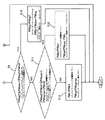
図1に示すように、エンジン1にパワーデバイダ2を介して油圧ポンプ3と、1台で発電機作用と電動機作用を行なう動力機としての発電機兼電動機4とがパラレルに接続され、これらがエンジン1によって駆動される。
As shown in FIG. 1, a
油圧ポンプ3には、制御弁(アクチュエータごとに設けられているが、ここでは複数の制御弁の集合体として示す)5を介して図示しない油圧アクチュエータ(たとえばショベルでいうとブーム、アーム、バケット各シリンダや走行用油圧モータ等)が接続され、油圧ポンプ3から供給される圧油によってこれら油圧アクチュエータが駆動される。なお、図1では油圧ポンプ3が一台のみ接続された場合を示しているが、複数台が直列または並列に接続される場合もある。
The
一方、発電機兼電動機4には、動力機制御手段としてのインバータ6を介して蓄電装置としてのバッテリ7が接続されている。
On the other hand, a
インバータ6は、発電機兼電動機4の発電機作用と電動機作用の切換え、発電電力、電動機としての電流またはトルクを制御するとともに、発電機兼電動機4の発電機出力に応じてバッテリ7の充・放電を制御する。
The
コントローラ8には、次の情報が入力される。
The
i. 図示しない電流センサによって検出されるバッテリ7の電流(これを積算することによってバッテリ充電量が求められる)。
i. Current of the
ii. 図示しないバッテリ温度センサによって検出されるバッテリ7の温度。
ii. The temperature of the
iii. アクチュエータ要求パワーを求めるためのパラメータである、油圧ポンプ3の圧力(吐出圧)と吐出量、それに回転数(ここでは発電機兼電動機4の回転数)。
iii. Pressure (discharge pressure) and discharge amount of the
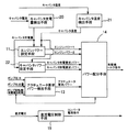
このコントローラ8の構成内容を図2に詳しく示す。
The configuration content of the
コントローラ8には、前記のようにバッテリ電流からバッテリ充電量を求めるバッテリ充電量検出手段9と、バッテリ温度を求めるバッテリ温度検出手段10と、バッテリ充電量と温度とに応じてエンジン1のパワーを設定するエンジンパワー設定手段11と、バッテリ充電量と温度とに応じてバッテリ7のパワー(充電要求パワー及び放電要求パワー)を設定するバッテリパワー設定手段12と、ポンプ圧力、吐出量、回転数からアクチュエータが要求しているパワーを求めるアクチュエータ要求パワー検出手段13と、エンジン1とバッテリ7のパワー配分を決定するパワー配分手段14とが設けられている。
As described above, the
バッテリパワー設定手段12においては、たとえば、図3,4に示すように予めバッテリ充電量(充電状態SOC=State of Charge)及び温度に対して充電要求パワー及び放電要求パワーをテーブル化しておき、検出されるバッテリ充電量及び温度に対応する数値を選択して設定する。 In the battery power setting means 12, for example, as shown in FIGS. 3 and 4, the charge request power and the discharge request power are tabulated in advance with respect to the battery charge amount (charge state SOC = State of Charge) and temperature, and detected. A numerical value corresponding to the battery charge amount and temperature to be selected is selected and set.
エンジンパワー設定手段11では、たとえば、図5,6に示すように、予めバッテリ充電量に対するエンジンパワーの関係(充電量が低いほどエンジンパワーを高くする)をテーブル化しておき、検出されるバッテリ充電量に対応するエンジンパワーを選択・設定する。 In the engine power setting means 11, for example, as shown in FIGS. 5 and 6, the relationship between the engine power and the battery charge amount (the engine power increases as the charge amount decreases) is tabulated in advance, and the detected battery charge is detected. Select and set the engine power corresponding to the quantity.
ここで、エンジンパワーの設定値は、エンジン1を高効率で運転し得る範囲として、図5に示す下限値(バッテリパワー1)と図6に示す上限値(バッテリパワー2)との間の数値として定められる。
Here, the set value of the engine power is a numerical value between the lower limit value (battery power 1) shown in FIG. 5 and the upper limit value (battery power 2) shown in FIG. 6 as a range in which the
一方、パワー配分手段14では、上記のように求められ、または設定されたアクチュエータ要求パワー、バッテリ充電要求パワー、バッテリ放電要求パワー、エンジンパワーに基づいて、エンジン1とバッテリ7のパワー配分を行なう。
On the other hand, the
この配分フローを図7,8に示す。 This distribution flow is shown in FIGS.
両図において、
PWpws : アクチュエータ要求パワー
PWbc : バッテリ充電要求パワー(≦0)
PWbd : バッテリ放電要求パワー(≧0)
PWeg1 : エンジンパワー1(エンジンパワー下限値) (≧0)
PWeg2 : エンジンパワー2(エンジンパワー上限値) (≧0)
PWegmax : エンジン最大パワー(≧0)
PWeg : エンジンパワー
PWb : バッテリパワー
ただし、PWegmaxはエンジンの性能によって決まる定数である。
In both figures,
PWpws: Required actuator power PWbc: Required battery charge power (≤0)
PWbd: Battery discharge required power (≧ 0)
PWeg1: Engine power 1 (engine power lower limit value) (≧ 0)
PWeg2: Engine power 2 (Engine power upper limit) (≧ 0)
PWegmax: Engine maximum power (≧ 0)
PWeg: engine power PWb: battery power However, PWegmax is a constant determined by engine performance.
また、図7,8において、バッテリ7の放電を+、充電を−としている。
7 and 8, the discharge of the
まず、図7のステップS1において、アクチュエータ要求パワーPWpwsとエンジンパワー下限値PWeg1とが比較され、アクチュエータ要求パワーPWpwsがエンジンパワー下限値PWeg1よりも小さい場合(YESの場合)は、ステップS2でエンジンパワーPWeg=エンジンパワー下限値PWeg1、バッテリパワーPWb=アクチュエータ要求パワーPWpws−エンジンパワーPWegとする。 First, in step S1 of FIG. 7, the actuator required power PWpws and the engine power lower limit value PWeg1 are compared. If the actuator required power PWpws is smaller than the engine power lower limit value PWeg1 (in the case of YES), the engine power is determined in step S2. PWeg = engine power lower limit PWeg1, battery power PWb = actuator required power PWpws−engine power PWeg.
ただし、ここでバッテリパワーPWb<バッテリ充電要求パワーPWbcとなった場合(バッテリパワーが充電能力を超える設定となる場合)は、
バッテリパワーPWb=バッテリ充電要求パワーPWbc、
エンジンパワーPWeg=
アクチュエータ要求パワーPWpws−バッテリパワーPWb
とする(ステップS3,S4)。
However, when battery power PWb <battery charge required power PWbc (when battery power is set to exceed the charging capacity),
Battery power PWb = required battery charge power PWbc,
Engine power PWeg =
Actuator required power PWpws-Battery power PWb
(Steps S3 and S4).
なお、エンジンパワー<0の場合はエンジンパワー=0とする(ステップS5,S6)。 When engine power <0, engine power = 0 is set (steps S5 and S6).
ステップS1でNOで、かつ、エンジンパワー1≦アクチュエータ要求パワーPWpws<エンジンパワー2の場合、つまりアクチュエータ要求パワーがエンジンパワー1とエンジンパワー2の間にある場合(ステップS7でYESの場合)は、
エンジンパワーPWeg=アクチュエータ要求パワーPWpws
バッテリパワーPWb=0
とする。すなわち、アクチュエータ要求パワーをエンジン1ですべて受け持つ設定とする(ステップS8)。
If NO in step S1 and
Engine power PWeg = Actuator required power PWpws
Battery power PWb = 0
And That is, the setting is such that all the required actuator power is handled by the engine 1 (step S8).
図8のステップS9において、エンジンパワー2≦アクチュエータ要求パワー<(エンジンパワー2+バッテリ放電要求パワー)と判断された場合、すなわちアクチュエータ要求パワーが、エンジンパワー2と、(エンジンパワー2+バッテリ放電要求パワー)の間にあると判断された場合、ステップS10で、
エンジンパワーPWeg=エンジンパワー2PWeg2
バッテリパワーPWb=
アクチュエータ要求パワーPWpws−エンジンパワーPWeg
とする。エンジン1はエンジンパワー2だけを受け持ち、残りはバッテリ7が受け持つ。
If it is determined in step S9 in FIG. 8 that
Engine power PWeg = Engine power 2PWeg2
Battery power PWb =
Actuator required power PWpws-Engine power PWeg
And The
一方、ステップS11で、(エンジンパワー2PWeg2+バッテリ放電要求パワーPWbd)≦アクチュエータ要求パワーPWpws<(エンジン最大パワーPWegmax+バッテリ放電要求パワーPWbd)と判断された場合、すなわちアクチュエータ要求パワーが(エンジンパワー2+バッテリ放電要求パワー)と(エンジン最大パワー+バッテリ放電要求パワー)の間にあると判断された場合、ステップS12で、
バッテリパワーPWb=バッテリ放電要求パワーPWbd
エンジンパワーPWeg=アクチュエータ要求パワーPWpws−バッテリパワーPWb
とし、バッテリ7はバッテリ放電要求パワーだけ受け持ち、残りはエンジン1が受け持つ。
On the other hand, if it is determined in step S11 that (engine power 2PWeg2 + required battery discharge power PWbd) ≦ actuator required power PWpws <(engine maximum power PWegmax + battery discharge required power PWbd), that is, the actuator required power is (
Battery power PWb = Battery discharge required power PWbd
Engine power PWeg = actuator required power PWpws−battery power PWb
The
これに対し、
(エンジン最大パワーPWegmax+バッテリ放電要求パワーPWbd)≦アクチュエータ要求パワーPWpwsの場合(ステップS11でNOの場合)、つまりアクチュエータ要求パワーがエンジン1とバッテリ7の能力を超えるパワーとなる場合は、
バッテリパワーPWb=バッテリ放電要求パワーPWbd
エンジンパワーPWeg=エンジン最大パワーPWegmax
とする(ステップS13)。
In contrast,
When (engine maximum power PWegmax + battery discharge required power PWbd) ≦ actuator required power PWpws (NO in step S11), that is, when the actuator required power exceeds the capabilities of
Battery power PWb = Battery discharge required power PWbd
Engine power PWeg = Engine maximum power PWegmax
(Step S13).
ところで、エンジンパワーPWegについては、その動特性から急激なパワー変動に対して応答遅れが発生する。そこで、パワー配分フローの中で、エンジンパワー設定値の変化量が予め定めた値を超える場合に、図9に示すように、ローパスフィルタ等を用いた補正処理により、エンジン出力の立ち上がりが動特性に応じたものとなる(たとえば段階的に上げる)ように補正エンジンパワーPWeg´を算出し設定する。 By the way, with respect to the engine power PWeg, a response delay occurs due to a sudden power fluctuation due to its dynamic characteristics. Therefore, when the amount of change in the engine power set value exceeds a predetermined value in the power distribution flow, as shown in FIG. 9, the rising of the engine output is caused to be dynamic by correction processing using a low-pass filter or the like. The corrected engine power PWeg ′ is calculated and set so as to be in accordance with (for example, stepwise increase).
また、この補正エンジンパワーPWeg´に基づいて新たに補正バッテリパワーPWb´を、
PWb´=PWpws−PWeg´
で算出する。
Further, based on the corrected engine power PWeg ′, a corrected battery power PWb ′ is newly set.
PWb ′ = PWpws−PWeg ′
Calculate with
ただし、補正バッテリパワーPWb´がバッテリ充電要求パワーPWbcより小さい場合は、
PWb´=PWbc
とし、補正バッテリパワーPWb´がバッテリ放電要求パワーPWbdよりも大きい場合は、
PWb´=PWbd
とする。このとき、PWeg´=PWpws−PWb´によりエンジンパワーを算出し直す。
However, when the corrected battery power PWb ′ is smaller than the battery charge request power PWbc,
PWb '= PWbc
When the corrected battery power PWb ′ is larger than the battery discharge required power PWbd,
PWb '= PWbd
And At this time, the engine power is recalculated by PWeg ′ = PWpws−PWb ′.
さらに、上記パワー配分に基づき、発電機兼電動機4のパワーを以下の式で求める。
Further, based on the power distribution, the power of the generator /
PWmg=PWpws−PWeg
PWmg:発電機パワー
Tqmg=PWpws/ωmg
Tqmg:発電機兼電動機4のトルク(発電機トルク)
ωmg:発電機兼電動機4の角速度(発電機兼電動機4の回転数から
求める)
こうして求められた発電機トルクが、パワー配分手段14から図1のインバータ6に発電機トルク指令値として送られ、これに基づいて発電機兼電動機4が上記指令値通りの出力トルクとなるように制御される。
PWmg = PWpws-PWeg
PWmg: Generator power Tqmg = PWpws / ωmg
Tqmg: Generator /
ωmg: Angular speed of the generator / motor 4 (from the rotational speed of the generator /
Ask)
The generator torque thus determined is sent from the power distribution means 14 to the
以上の制御により、バッテリ7の充放電パワー及びエンジンパワーがバッテリ7の充電量に応じて設定され、この設定値と、アクチュエータ要求パワーとに基づいてエンジン1と動力機4のパワー配分が行なわれるため、バッテリ7の充電量が一定範囲、つまりバッテリ能力を有効利用でき、かつ、過充電、過放電を防止してバッテリ7の劣化を抑制し得る範囲に保たれる。
With the above control, the charge / discharge power and engine power of the
また、バッテリ7の温度に応じて充放電パワーが設定されるため、この充放電パワーをバッテリ温度に対応した適正値とすることができる。
Moreover, since charging / discharging power is set according to the temperature of the
さらに、エンジンパワー設定手段11においてエンジンパワーの下限値(PWeg1)と上限値(PWeg2)を定め、この下限値と上限値の間で、バッテリ7の充電量に応じてエンジンパワーを設定するため、この設定範囲をエンジンを高効率で運転し得る範囲として定めておくことにより、エンジン1の運転効率を高めることができる。
Further, the engine power setting means 11 determines a lower limit value (PWeg1) and an upper limit value (PWeg2) of the engine power, and sets the engine power according to the charge amount of the
また、パワー配分手段14において、エンジンの動特性に応じてエンジンパワーが変化するようにエンジンパワー設定値を補正するため、エンジンのパワー負担が急激に増加することによるエンジン回転数の低下やエンストを防止することができる。 Further, since the power distribution means 14 corrects the engine power setting value so that the engine power changes according to the dynamic characteristics of the engine, a decrease in engine speed and engine stall due to a sudden increase in the engine power burden are reduced. Can be prevented.
以上の点により、エンジン1の高効率運転を行いつつバッテリ7の充電量をコントロールして、ハイブリッドシステムの動力源の性能を有効に利用することができる。
From the above points, it is possible to effectively use the performance of the power source of the hybrid system by controlling the charge amount of the
第2実施形態(図10,11参照)
第2実施形態では、蓄電装置としてキャパシタ15を用いている。
Second embodiment (see FIGS. 10 and 11)
In the second embodiment, the
この装置の基本システム構成としては、
イ) 図1のバッテリ7がキャパシタ15に置き換えられている点、
ロ) その制御器としてコンバータ16が設けられている点、
ハ) インバータ6とコンバータ16とを結ぶ直流回路に直流電圧を検出する電圧センサ17が設けられている点
以外は第1実施形態の場合と同じである。
As a basic system configuration of this device,
A) The
B) A
C) The present embodiment is the same as the first embodiment except that a
また、コントローラ18の構成において、図11に示すように直流電圧制御手段19が付加されている点のみが第1実施形態(図1,2)のコントローラ8と異なり、図11中のキャパシタ充電量検出手段20、キャパシタ温度検出手段21、キャパシタパワー設定手段22は、それぞれ図2中のバッテリ充電量検出手段9、バッテリ温度検出手段10、バッテリパワー設定手段12に相当する。
11 is different from the
さらに、作用も基本的には第1実施形態と同じで、キャパシタ15の充電量及び温度に応じて、キャパシタパワー設定手段22で図3,4と同様な充放電特性が設定されるとともに、エンジンパワー設定手段11において図5,6と同様なエンジンパワーの設定が行なわれる。
Further, the operation is basically the same as in the first embodiment, and the charge / discharge characteristics similar to those of FIGS. 3 and 4 are set by the capacitor power setting means 22 in accordance with the charge amount and temperature of the
パワー配分手段14においても、図7,8と同様の配分フローによってエンジン1とキャパシタ15のパワー配分が行なわれる。
Also in the power distribution means 14, the power distribution of the
直流電圧制御手段19では、インバータ6とコンバータ16とを結ぶ直流回路の電圧をフィードバックすることにより、直流電圧が一定となるようにコンバータ16に電流指令を出力する。
The DC voltage control means 19 outputs a current command to the
この第2実施形態によっても、第1実施形態と同様の効果(エンジン1を高効率で運転しながらキャパシタ15の充電量を一定範囲に保つ)を得ることができる。
According to the second embodiment, it is possible to obtain the same effect as that of the first embodiment (keeping the charge amount of the
ところで、上記実施形態では発電機と電動機が一体に構成された発電機兼電動機4を用いたが、発電機と電動機を別体として設けてもよい。
By the way, in the said embodiment, although the generator and
また、上記実施形態では蓄電装置(バッテリまたはキャパシタ)の充電量と温度の双方を検出する構成をとったが、充電量のみを検出する構成をとってもよい。あるいは、双方を検出する場合と充電量のみを検出する場合とに切換えるようにしてもよい。 In the above embodiment, the configuration is such that both the charge amount and the temperature of the power storage device (battery or capacitor) are detected. However, a configuration may be adopted in which only the charge amount is detected. Or you may make it switch between the case where both are detected and the case where only charge amount is detected.
さらに、蓄電装置としてバッテリとキャパシタの両者を併用してもよい。 Furthermore, you may use both a battery and a capacitor together as an electrical storage apparatus.
1 エンジン
3 油圧ポンプ
4 発電機兼電動機(動力機)
6 動力機制御手段としてのインバータ
7 蓄電装置としてのバッテリ
8 コントローラ
9 バッテリ充電量検出手段
10 バッテリ温度検出手段
11 エンジンパワー設定手段
12 バッテリパワー設定手段
13 アクチュエータ要求パワー検出手段
14 パワー配分手段
15 蓄電装置としてのキャパシタ
18 コントローラ
20 キャパシタ充電量検出手段
21 キャパシタ温度検出手段
22 キャパシタパワー設定手段
1
6 Inverter as power machine control means 7 Battery as
Claims (5)
(A) 上記油圧アクチュエータが要求するパワーであるアクチュエータ要求パワーを求めるアクチュエータ要求パワー検出手段、
(B) 上記蓄電装置の充電量を求める充電量検出手段、
(C) 上記蓄電装置の充電量が一定範囲内に保たれる方向で、充電量の変化に応じて充電パワー及び放電パワーを設定する蓄電装置パワー設定手段、
(D) 上記蓄電装置の充電量に応じて上記エンジンのパワーを設定するエンジンパワー設定手段、
(E) 上記アクチュエータ要求パワーと、設定された蓄電装置の充電パワー及び放電パワーと、設定されたエンジンパワーとに基づいてエンジンと上記動力機のパワー配分を決定するパワー配分手段、
(F) このパワー配分手段によって決定されたパワー配分に基づいて動力機のパワーを制御する動力機制御手段。 A hydraulic pump that drives the hydraulic actuator and a power machine that performs a generator action and a motor action are connected in parallel to an engine as a common power source. A power source device for a work machine, wherein the power machine is driven by the discharge force of the device to perform an electric motor action, and includes the following means.
(A) Actuator required power detection means for obtaining an actuator required power that is a power required by the hydraulic actuator,
(B) Charge amount detection means for obtaining the charge amount of the power storage device;
(C) Power storage device power setting means for setting charging power and discharge power in accordance with changes in the charge amount in a direction in which the charge amount of the power storage device is maintained within a certain range;
(D) engine power setting means for setting the power of the engine according to the charge amount of the power storage device;
(E) power distribution means for determining power distribution between the engine and the power machine based on the actuator required power, the set charging power and discharging power of the power storage device, and the set engine power;
(F) Power machine control means for controlling the power of the power machine based on the power distribution determined by the power distribution means.
Priority Applications (5)
| Application Number | Priority Date | Filing Date | Title |
|---|---|---|---|
| JP2004046832A JP2005237178A (en) | 2004-02-23 | 2004-02-23 | Power source apparatus for working machine |
| EP05703422A EP1720244A4 (en) | 2004-02-23 | 2005-01-11 | Power source device for working machine |
| US10/588,704 US7525206B2 (en) | 2004-02-23 | 2005-01-11 | Power source device for working machine |
| CNB2005800057371A CN100468951C (en) | 2004-02-23 | 2005-01-11 | Power source device for working machine |
| PCT/JP2005/000183 WO2005081393A1 (en) | 2004-02-23 | 2005-01-11 | Power source device for working machine |
Applications Claiming Priority (1)
| Application Number | Priority Date | Filing Date | Title |
|---|---|---|---|
| JP2004046832A JP2005237178A (en) | 2004-02-23 | 2004-02-23 | Power source apparatus for working machine |
Publications (1)
| Publication Number | Publication Date |
|---|---|
| JP2005237178A true JP2005237178A (en) | 2005-09-02 |
Family
ID=34879452
Family Applications (1)
| Application Number | Title | Priority Date | Filing Date |
|---|---|---|---|
| JP2004046832A Pending JP2005237178A (en) | 2004-02-23 | 2004-02-23 | Power source apparatus for working machine |
Country Status (5)
| Country | Link |
|---|---|
| US (1) | US7525206B2 (en) |
| EP (1) | EP1720244A4 (en) |
| JP (1) | JP2005237178A (en) |
| CN (1) | CN100468951C (en) |
| WO (1) | WO2005081393A1 (en) |
Cited By (22)
| Publication number | Priority date | Publication date | Assignee | Title |
|---|---|---|---|---|
| JP2007151263A (en) * | 2005-11-25 | 2007-06-14 | Mitsubishi Heavy Ind Ltd | Power distribution control device and hybrid construction machine |
| JP2007290607A (en) * | 2006-04-26 | 2007-11-08 | Kobelco Contstruction Machinery Ltd | Power source device of hybrid type working machine |
| JP2008088660A (en) * | 2006-09-29 | 2008-04-17 | Kobelco Contstruction Machinery Ltd | Hybrid work machine |
| WO2008120682A1 (en) * | 2007-03-29 | 2008-10-09 | Komatsu Ltd. | Construction machine and control method of construction machine |
| JP2009052339A (en) * | 2007-08-28 | 2009-03-12 | Toshiba Mach Co Ltd | Operation control method of hybrid type working machine and working machine using the same method |
| WO2009084673A1 (en) | 2007-12-28 | 2009-07-09 | Sumitomo Heavy Industries, Ltd. | Hybrid construction machine |
| JP2009208512A (en) * | 2008-02-29 | 2009-09-17 | Mitsubishi Heavy Ind Ltd | Method of controlling work vehicle, and work vehicle |
| WO2010087363A1 (en) * | 2009-01-28 | 2010-08-05 | 住友重機械工業株式会社 | Hybrid working machine and electricity storage control apparatus |
| JP2010178446A (en) * | 2009-01-28 | 2010-08-12 | Sumitomo Heavy Ind Ltd | Hybrid working machine |
| JP2010193630A (en) * | 2009-02-18 | 2010-09-02 | Sumitomo Heavy Ind Ltd | Power storage control device and working machine |
| JP2011012481A (en) * | 2009-07-03 | 2011-01-20 | Sumitomo Heavy Ind Ltd | Hybrid type working machine and method for computing efficiency coefficient of the same |
| EP2377710A2 (en) | 2010-04-14 | 2011-10-19 | Kobelco Construction Machinery Co. Ltd. | Hybrid working machine having battery protecting function |
| JP4843105B2 (en) * | 2008-11-28 | 2011-12-21 | 住友重機械工業株式会社 | Control method for hybrid work machine and pump output limiting method for hybrid work machine |
| WO2012023231A1 (en) | 2010-08-18 | 2012-02-23 | 川崎重工業株式会社 | Electro-hydraulic drive system for a work machine |
| WO2012118027A1 (en) * | 2011-03-01 | 2012-09-07 | 日立建機株式会社 | Hybrid-type construction machine |
| JP2014047501A (en) * | 2012-08-30 | 2014-03-17 | Kobelco Contstruction Machinery Ltd | Power storage device warming-up device of hybrid construction machine |
| JP2014051795A (en) * | 2012-09-06 | 2014-03-20 | Kobelco Contstruction Machinery Ltd | Power control device for hybrid construction machine |
| JP2014083908A (en) * | 2012-10-22 | 2014-05-12 | Kobe Steel Ltd | Construction machine |
| JP2015034376A (en) * | 2013-08-07 | 2015-02-19 | コベルコ建機株式会社 | Swivel motor speed control device for hybrid construction machine |
| WO2015133625A1 (en) * | 2014-03-06 | 2015-09-11 | 住友建機株式会社 | Excavator |
| WO2015151926A1 (en) * | 2014-03-31 | 2015-10-08 | 住友建機株式会社 | Shovel |
| CN113147720A (en) * | 2021-05-08 | 2021-07-23 | 湖南三一路面机械有限公司 | Hybrid power apparatus, hybrid power system, and control method of hybrid power system |
Families Citing this family (36)
| Publication number | Priority date | Publication date | Assignee | Title |
|---|---|---|---|---|
| CN101297083B (en) * | 2005-10-31 | 2011-07-06 | 株式会社小松制作所 | Control device of work machine |
| FI118882B (en) * | 2005-11-28 | 2008-04-30 | Ponsse Oyj | Method and apparatus for power transmission in a forest machine |
| US8100210B2 (en) * | 2006-02-07 | 2012-01-24 | Takeuchi Mfg. Co., Ltd | Electrically driven industrial vehicle |
| JP4524679B2 (en) * | 2006-03-15 | 2010-08-18 | コベルコ建機株式会社 | Hybrid construction machinery |
| US7973499B2 (en) * | 2006-06-01 | 2011-07-05 | Takeuchi Mfg. Co., Ltd. | Working vehicle |
| US9032725B2 (en) | 2006-10-06 | 2015-05-19 | Volvo Construction Equipment Ab | Method for operating a working machine and a working machine |
| JP5055948B2 (en) * | 2006-10-20 | 2012-10-24 | コベルコ建機株式会社 | Hybrid work machine |
| JP2008121659A (en) * | 2006-10-20 | 2008-05-29 | Kobelco Contstruction Machinery Ltd | Hybrid operation machine |
| US20090091301A1 (en) * | 2007-10-08 | 2009-04-09 | Sauer-Danfoss Inc. | Load lowering regenerative energy system with capacitor charge and discharge circuit and method of operating the same |
| US7900724B2 (en) * | 2008-03-20 | 2011-03-08 | Terex-Telelect, Inc. | Hybrid drive for hydraulic power |
| US8510000B2 (en) * | 2008-03-26 | 2013-08-13 | Kayaba Industry Co., Ltd. | Hybrid construction machine |
| KR101270715B1 (en) * | 2008-12-01 | 2013-06-03 | 스미토모 겐키 가부시키가이샤 | Hybrid construction machine |
| JP5401992B2 (en) * | 2009-01-06 | 2014-01-29 | コベルコ建機株式会社 | Power source device for hybrid work machine |
| CA2760846A1 (en) * | 2009-05-12 | 2010-11-18 | El-Forest Ab | Energy system for a hybrid vehicle |
| KR101112137B1 (en) * | 2009-07-29 | 2012-02-22 | 볼보 컨스트럭션 이큅먼트 에이비 | Control System and Method For Reducing Change Of RPM In Hybrid Type Construction Machine |
| US8718844B2 (en) * | 2010-07-19 | 2014-05-06 | General Motors Llc | Charge notification method for extended range electric vehicles |
| JP5764310B2 (en) * | 2010-10-27 | 2015-08-19 | ヤンマー株式会社 | Power transmission device |
| JP5764311B2 (en) * | 2010-10-27 | 2015-08-19 | ヤンマー株式会社 | Power transmission device |
| US8606444B2 (en) * | 2010-12-29 | 2013-12-10 | Caterpillar Inc. | Machine and power system with electrical energy storage device |
| JP5690604B2 (en) * | 2011-02-01 | 2015-03-25 | 日立建機株式会社 | Work machine |
| JP5585488B2 (en) * | 2011-02-17 | 2014-09-10 | コベルコ建機株式会社 | Power source device for hybrid construction machinery |
| CN102152782A (en) * | 2011-03-24 | 2011-08-17 | 江苏柳工机械有限公司 | Power distribution control method and system for mobile operation machine |
| KR101776965B1 (en) * | 2011-08-26 | 2017-09-08 | 두산인프라코어 주식회사 | Hybrid power supply and controlling method thereof |
| JP5970898B2 (en) * | 2012-03-26 | 2016-08-17 | コベルコ建機株式会社 | Power transmission device and hybrid construction machine equipped with the same |
| JP6232795B2 (en) * | 2013-07-18 | 2017-11-22 | コベルコ建機株式会社 | Hybrid construction machinery |
| JP6355347B2 (en) * | 2014-01-30 | 2018-07-11 | 日立建機株式会社 | Hybrid construction machine |
| JP6091444B2 (en) | 2014-02-03 | 2017-03-08 | 日立建機株式会社 | Hybrid construction machinery |
| JP6159681B2 (en) * | 2014-05-07 | 2017-07-05 | 日立建機株式会社 | Hybrid work machine |
| JP6247617B2 (en) * | 2014-09-12 | 2017-12-13 | 日立建機株式会社 | Construction machinery |
| JP6243857B2 (en) * | 2015-01-23 | 2017-12-06 | 日立建機株式会社 | Hybrid construction machinery |
| KR20170117151A (en) | 2015-03-25 | 2017-10-20 | 가부시키가이샤 케이씨엠 | Hybrid-type working vehicle |
| JP6419063B2 (en) * | 2015-12-24 | 2018-11-07 | 日立建機株式会社 | Hybrid work machine |
| CN109665470B (en) * | 2018-12-29 | 2020-11-03 | 徐州海伦哲特种车辆有限公司 | Energy-saving control system and control method for electric aerial work vehicle |
| US11511642B2 (en) | 2019-04-05 | 2022-11-29 | Oshkosh Corporation | Electric concrete vehicle systems and methods |
| EP4041583A1 (en) | 2019-10-11 | 2022-08-17 | Oshkosh Corporation | Operational modes for hybrid fire fighting vehicle |
| GB2592237B (en) * | 2020-02-20 | 2022-07-20 | Terex Gb Ltd | Material processing apparatus with hybrid power system |
Family Cites Families (20)
| Publication number | Priority date | Publication date | Assignee | Title |
|---|---|---|---|---|
| JPH1042587A (en) | 1996-07-22 | 1998-02-13 | Daikin Ind Ltd | Hydraulic drive device |
| JP3775012B2 (en) * | 1997-08-29 | 2006-05-17 | アイシン・エィ・ダブリュ株式会社 | Hybrid drive device for vehicle |
| DE19804204C2 (en) * | 1998-02-03 | 2001-03-22 | Tax Technical Consultancy Gmbh | Vehicle for moving loads |
| US6276472B1 (en) * | 1998-04-01 | 2001-08-21 | Denso Corporation | Control system for hybrid vehicle |
| US6349543B1 (en) * | 1998-06-30 | 2002-02-26 | Robert Moshe Lisniansky | Regenerative adaptive fluid motor control |
| JP2000226183A (en) * | 1999-02-04 | 2000-08-15 | Komatsu Ltd | Hybrid type working vehicle |
| WO2001000934A1 (en) * | 1999-06-25 | 2001-01-04 | Kobelco Construction Machinery Co., Ltd. | Hybrid construction machinery and control device of the construction machinery |
| JP2001268714A (en) | 2000-03-22 | 2001-09-28 | Hitachi Ltd | Hybrid vehicle control device |
| JP4520649B2 (en) * | 2001-02-06 | 2010-08-11 | 株式会社小松製作所 | Hybrid construction machine |
| JP4480908B2 (en) * | 2001-02-19 | 2010-06-16 | 住友建機株式会社 | Hybrid excavator |
| JP4512283B2 (en) * | 2001-03-12 | 2010-07-28 | 株式会社小松製作所 | Hybrid construction machine |
| JP2002330554A (en) * | 2001-04-27 | 2002-11-15 | Kobelco Contstruction Machinery Ltd | Power control device for hybrid vehicle and hybrid construction machine equipped with the power control device |
| JP2002359935A (en) | 2001-05-31 | 2002-12-13 | Komatsu Ltd | Charging/discharging control device for power storing part of hybrid work machine |
| JP3638263B2 (en) * | 2001-09-10 | 2005-04-13 | 本田技研工業株式会社 | Vehicle drive device |
| JP2003328397A (en) | 2002-05-08 | 2003-11-19 | Hitachi Constr Mach Co Ltd | Hybrid construction machine |
| JP3833573B2 (en) * | 2002-06-06 | 2006-10-11 | 新キャタピラー三菱株式会社 | Hybrid construction machine |
| JP3781366B2 (en) | 2002-07-23 | 2006-05-31 | 本田技研工業株式会社 | Secondary battery charge / discharge controller |
| JP4047110B2 (en) * | 2002-09-11 | 2008-02-13 | 株式会社小松製作所 | Construction machinery |
| JP2004340055A (en) * | 2003-05-16 | 2004-12-02 | Honda Motor Co Ltd | Hybrid drive |
| JP5055972B2 (en) * | 2006-01-12 | 2012-10-24 | 株式会社豊田自動織機 | Industrial vehicle cargo handling equipment |
-
2004
- 2004-02-23 JP JP2004046832A patent/JP2005237178A/en active Pending
-
2005
- 2005-01-11 EP EP05703422A patent/EP1720244A4/en not_active Withdrawn
- 2005-01-11 CN CNB2005800057371A patent/CN100468951C/en not_active Expired - Fee Related
- 2005-01-11 US US10/588,704 patent/US7525206B2/en active Active
- 2005-01-11 WO PCT/JP2005/000183 patent/WO2005081393A1/en active Application Filing
Cited By (51)
| Publication number | Priority date | Publication date | Assignee | Title |
|---|---|---|---|---|
| JP4563302B2 (en) * | 2005-11-25 | 2010-10-13 | 三菱重工業株式会社 | Power distribution control device and hybrid construction machine |
| JP2007151263A (en) * | 2005-11-25 | 2007-06-14 | Mitsubishi Heavy Ind Ltd | Power distribution control device and hybrid construction machine |
| JP2007290607A (en) * | 2006-04-26 | 2007-11-08 | Kobelco Contstruction Machinery Ltd | Power source device of hybrid type working machine |
| JP4725406B2 (en) * | 2006-04-26 | 2011-07-13 | コベルコ建機株式会社 | Power source device for hybrid work machines |
| JP2008088660A (en) * | 2006-09-29 | 2008-04-17 | Kobelco Contstruction Machinery Ltd | Hybrid work machine |
| JP4678353B2 (en) * | 2006-09-29 | 2011-04-27 | コベルコ建機株式会社 | Hybrid work machine |
| JP4862078B2 (en) * | 2007-03-29 | 2012-01-25 | 株式会社小松製作所 | Construction machine and method for controlling construction machine |
| WO2008120682A1 (en) * | 2007-03-29 | 2008-10-09 | Komatsu Ltd. | Construction machine and control method of construction machine |
| US8214110B2 (en) | 2007-03-29 | 2012-07-03 | Komatsu Ltd. | Construction machine and method of controlling construction machine |
| KR101391104B1 (en) | 2007-03-29 | 2014-04-30 | 가부시키가이샤 고마쓰 세이사쿠쇼 | Construction machine and control method of construction machine |
| DE112008000671B4 (en) * | 2007-03-29 | 2015-04-16 | Komatsu Ltd. | Construction machine and method for controlling a construction machine |
| CN101636542B (en) * | 2007-03-29 | 2011-12-07 | 株式会社小松制作所 | Construction machine and control method of construction machine |
| JP2009052339A (en) * | 2007-08-28 | 2009-03-12 | Toshiba Mach Co Ltd | Operation control method of hybrid type working machine and working machine using the same method |
| US8285434B2 (en) | 2007-12-28 | 2012-10-09 | Sumitomo Heavy Industries, Ltd. | Hybrid-type construction machine having an output condition calculating unit to calculate output conditions of an engine and an electric storage device |
| WO2009084673A1 (en) | 2007-12-28 | 2009-07-09 | Sumitomo Heavy Industries, Ltd. | Hybrid construction machine |
| JP2009208512A (en) * | 2008-02-29 | 2009-09-17 | Mitsubishi Heavy Ind Ltd | Method of controlling work vehicle, and work vehicle |
| US8718843B2 (en) | 2008-02-29 | 2014-05-06 | Mitsubishi Nichiyu Forklift Co., Ltd. | Control method for industrial vehicle and industrial vehicle |
| JP4843105B2 (en) * | 2008-11-28 | 2011-12-21 | 住友重機械工業株式会社 | Control method for hybrid work machine and pump output limiting method for hybrid work machine |
| US9000716B2 (en) | 2009-01-28 | 2015-04-07 | Sumitomo Heavy Industries, Ltd. | Hybrid working machine and electric power accumulation controller |
| WO2010087363A1 (en) * | 2009-01-28 | 2010-08-05 | 住友重機械工業株式会社 | Hybrid working machine and electricity storage control apparatus |
| KR101307198B1 (en) * | 2009-01-28 | 2013-09-11 | 스미도모쥬기가이고교 가부시키가이샤 | Hybrid working machine and electricity storage control apparatus |
| JP2010178446A (en) * | 2009-01-28 | 2010-08-12 | Sumitomo Heavy Ind Ltd | Hybrid working machine |
| JP2010193630A (en) * | 2009-02-18 | 2010-09-02 | Sumitomo Heavy Ind Ltd | Power storage control device and working machine |
| JP2011012481A (en) * | 2009-07-03 | 2011-01-20 | Sumitomo Heavy Ind Ltd | Hybrid type working machine and method for computing efficiency coefficient of the same |
| US8421415B2 (en) | 2010-04-14 | 2013-04-16 | Kobelco Construction Machinery Co., Ltd. | Hybrid working machine having battery protecting function |
| EP2377710A2 (en) | 2010-04-14 | 2011-10-19 | Kobelco Construction Machinery Co. Ltd. | Hybrid working machine having battery protecting function |
| JP2011220068A (en) * | 2010-04-14 | 2011-11-04 | Kobelco Contstruction Machinery Ltd | Hybrid work machine |
| US9109586B2 (en) | 2010-08-18 | 2015-08-18 | Kawasaki Jukogyo Kabushiki Kaisha | Electro-hydraulic drive system for a work machine |
| KR101342565B1 (en) | 2010-08-18 | 2013-12-17 | 카와사키 주코교 카부시키 카이샤 | Electricity-liquid drive system of operating machine |
| JP2012041978A (en) * | 2010-08-18 | 2012-03-01 | Kawasaki Heavy Ind Ltd | Electro-hydraulic drive system for work machine |
| WO2012023231A1 (en) | 2010-08-18 | 2012-02-23 | 川崎重工業株式会社 | Electro-hydraulic drive system for a work machine |
| EP2682532A1 (en) * | 2011-03-01 | 2014-01-08 | Hitachi Construction Machinery Co., Ltd. | Hybrid-type construction machine |
| JP2012180681A (en) * | 2011-03-01 | 2012-09-20 | Hitachi Constr Mach Co Ltd | Hybrid construction machine |
| CN103384747A (en) * | 2011-03-01 | 2013-11-06 | 日立建机株式会社 | Hybrid-type construction machine |
| US8825316B2 (en) | 2011-03-01 | 2014-09-02 | Hitachi Construction Machinery Co., Ltd. | Hybrid-type construction machine |
| EP2682532A4 (en) * | 2011-03-01 | 2015-04-22 | Hitachi Construction Machinery | Hybrid-type construction machine |
| WO2012118027A1 (en) * | 2011-03-01 | 2012-09-07 | 日立建機株式会社 | Hybrid-type construction machine |
| JP2014047501A (en) * | 2012-08-30 | 2014-03-17 | Kobelco Contstruction Machinery Ltd | Power storage device warming-up device of hybrid construction machine |
| JP2014051795A (en) * | 2012-09-06 | 2014-03-20 | Kobelco Contstruction Machinery Ltd | Power control device for hybrid construction machine |
| JP2014083908A (en) * | 2012-10-22 | 2014-05-12 | Kobe Steel Ltd | Construction machine |
| JP2015034376A (en) * | 2013-08-07 | 2015-02-19 | コベルコ建機株式会社 | Swivel motor speed control device for hybrid construction machine |
| WO2015133625A1 (en) * | 2014-03-06 | 2015-09-11 | 住友建機株式会社 | Excavator |
| KR20160130749A (en) * | 2014-03-06 | 2016-11-14 | 스미토모 겐키 가부시키가이샤 | Excavator |
| JPWO2015133625A1 (en) * | 2014-03-06 | 2017-04-06 | 住友建機株式会社 | Excavator |
| US10060096B2 (en) | 2014-03-06 | 2018-08-28 | Sumitomo (S.H.I.) Construction Machinery Co., Ltd. | Shovel |
| KR102238170B1 (en) | 2014-03-06 | 2021-04-07 | 스미토모 겐키 가부시키가이샤 | Excavator |
| WO2015151926A1 (en) * | 2014-03-31 | 2015-10-08 | 住友建機株式会社 | Shovel |
| JPWO2015151926A1 (en) * | 2014-03-31 | 2017-04-13 | 住友建機株式会社 | Excavator |
| US9702116B2 (en) | 2014-03-31 | 2017-07-11 | Sumitomo (S.H.I.) Construction Machinery Co., Ltd. | Shovel with enhanced engine speed management using power storage device |
| CN113147720A (en) * | 2021-05-08 | 2021-07-23 | 湖南三一路面机械有限公司 | Hybrid power apparatus, hybrid power system, and control method of hybrid power system |
| CN113147720B (en) * | 2021-05-08 | 2022-08-26 | 湖南三一路面机械有限公司 | Hybrid power apparatus, hybrid power system, and control method of hybrid power system |
Also Published As
| Publication number | Publication date |
|---|---|
| US20070187180A1 (en) | 2007-08-16 |
| CN100468951C (en) | 2009-03-11 |
| EP1720244A1 (en) | 2006-11-08 |
| US7525206B2 (en) | 2009-04-28 |
| CN1922782A (en) | 2007-02-28 |
| EP1720244A4 (en) | 2012-05-16 |
| WO2005081393A1 (en) | 2005-09-01 |
Similar Documents
| Publication | Publication Date | Title |
|---|---|---|
| JP2005237178A (en) | Power source apparatus for working machine | |
| JP4725406B2 (en) | Power source device for hybrid work machines | |
| US9203261B2 (en) | Excavator | |
| EP1834854B1 (en) | Hybrid construction machine | |
| US8468816B2 (en) | Hybrid working machine | |
| EP2441894B1 (en) | Hybrid excavator and method of controlling hybrid excavator | |
| JP5591354B2 (en) | Hybrid work machine and control method of hybrid work machine | |
| JP5225779B2 (en) | Charge / discharge control method | |
| JP6325032B2 (en) | Excavator | |
| JP2008255699A (en) | Control device for hybrid work machine | |
| JP4678353B2 (en) | Hybrid work machine | |
| US9441345B2 (en) | Hybrid excavator and method of controlling hybrid excavator | |
| JP2005233164A (en) | Power source device of working machine | |
| JP6245828B2 (en) | Work machine and control method of work machine | |
| JP2007191973A (en) | Power control system for hybrid | |
| JP6490668B2 (en) | Excavator | |
| JP2013119761A (en) | Hybrid construction machine | |
| JP6316623B2 (en) | Excavator | |
| JP2012017676A (en) | Control system in hybrid construction machine | |
| JP2021065077A (en) | Power supply device and motor unit |
Legal Events
| Date | Code | Title | Description |
|---|---|---|---|
| A131 | Notification of reasons for refusal |
Free format text: JAPANESE INTERMEDIATE CODE: A131 Effective date: 20080205 |
|
| A521 | Written amendment |
Free format text: JAPANESE INTERMEDIATE CODE: A523 Effective date: 20080404 |
|
| A02 | Decision of refusal |
Free format text: JAPANESE INTERMEDIATE CODE: A02 Effective date: 20081104 |
|
| A521 | Written amendment |
Free format text: JAPANESE INTERMEDIATE CODE: A523 Effective date: 20081226 |
|
| A911 | Transfer to examiner for re-examination before appeal (zenchi) |
Free format text: JAPANESE INTERMEDIATE CODE: A911 Effective date: 20090107 |
|
| A912 | Re-examination (zenchi) completed and case transferred to appeal board |
Free format text: JAPANESE INTERMEDIATE CODE: A912 Effective date: 20090206 |