WO2015133579A1 - Dispositif de terminal, dispositif de station de base, système de communications, procédé de commande et circuit intégré - Google Patents
Dispositif de terminal, dispositif de station de base, système de communications, procédé de commande et circuit intégré Download PDFInfo
- Publication number
- WO2015133579A1 WO2015133579A1 PCT/JP2015/056532 JP2015056532W WO2015133579A1 WO 2015133579 A1 WO2015133579 A1 WO 2015133579A1 JP 2015056532 W JP2015056532 W JP 2015056532W WO 2015133579 A1 WO2015133579 A1 WO 2015133579A1
- Authority
- WO
- WIPO (PCT)
- Prior art keywords
- cell
- base station
- terminal device
- power headroom
- secondary cell
- Prior art date
Links
Images


Classifications
-
- H—ELECTRICITY
- H04—ELECTRIC COMMUNICATION TECHNIQUE
- H04W—WIRELESS COMMUNICATION NETWORKS
- H04W52/00—Power management, e.g. TPC [Transmission Power Control], power saving or power classes
- H04W52/04—TPC
- H04W52/30—TPC using constraints in the total amount of available transmission power
- H04W52/36—TPC using constraints in the total amount of available transmission power with a discrete range or set of values, e.g. step size, ramping or offsets
- H04W52/365—Power headroom reporting
-
- H—ELECTRICITY
- H04—ELECTRIC COMMUNICATION TECHNIQUE
- H04W—WIRELESS COMMUNICATION NETWORKS
- H04W52/00—Power management, e.g. TPC [Transmission Power Control], power saving or power classes
- H04W52/04—TPC
- H04W52/30—TPC using constraints in the total amount of available transmission power
- H04W52/34—TPC management, i.e. sharing limited amount of power among users or channels or data types, e.g. cell loading
-
- H—ELECTRICITY
- H04—ELECTRIC COMMUNICATION TECHNIQUE
- H04W—WIRELESS COMMUNICATION NETWORKS
- H04W72/00—Local resource management
- H04W72/20—Control channels or signalling for resource management
- H04W72/21—Control channels or signalling for resource management in the uplink direction of a wireless link, i.e. towards the network
Definitions
- Embodiments described herein relate generally to a terminal device, a base station device, a communication system, a control method, and an integrated circuit technology that efficiently control a plurality of cells.
- 3GPP 3rd Generation Partnership Project
- 3GPP which is a standardization project, has evolved to realize high-speed communication by adopting OFDM (Orthogonal Frequency Frequency Division) Multiplexing (OFDM) communication schemes and flexible scheduling in predetermined frequency and time units called resource blocks.
- OFDM Orthogonal Frequency Frequency Division
- EUTRA Universal Terrestrial Radio Access
- 3GPP is studying Advanced EUTRA that realizes higher-speed data transmission (also referred to as LTE Advanced).
- EUTRA the base station apparatus is a communication system based on a network having almost the same cell configuration (cell size).
- base station apparatuses (cells) having different configurations are mixed in the same area.
- Communication systems based on existing networks heterogeneous wireless networks, heterogeneous networks are being studied.
- Non-patent Document 1 a technology for performing communication (Dual Connectivity (dual connectivity, dual connectivity)) has been studied (Non-patent Document 1).
- Non-Patent Document 1 when a terminal device attempts to realize dual connectivity between a cell (macro cell) having a large cell radius (cell size) and a cell (small cell) having a small cell radius, Studies on networks based on the assumption that the backbone line (Backhaul) is low speed and delay occurs are underway. That is, the delay of the control information or user information exchanged between the macro cell and the small cell may make it impossible or impossible to realize a function that could be realized in the past in dual connectivity.
- Non-patent Document 2 a method of controlling packet scheduling in a distributed manner by providing a dynamic resource allocation function in both the macro cell base station apparatus and the small cell base station apparatus has been studied.
- Non-Patent Document 2 by performing distributed packet scheduling between base station apparatuses, the terminal apparatus directly sends feedback information to each base station apparatus without going through the backbone line between the base station apparatuses. Can be sent.
- each base station apparatus may not be able to grasp in real time the state of a cell managed by the other base station apparatus.
- the same identifier may be set with respect to a different cell.
- the terminal device cannot correctly report on the cell using the identifier.
- a mechanism for ensuring that the same identifier is not set for different cells has not been studied.
- control regarding a cell using an identifier for a terminal device when it is ensured that the same identifier is not set for different cells has not been studied.
- An embodiment of the present invention provides at least one of the above-described problems by providing a technology related to a terminal device, a base station device, a communication system, a control method, and an integrated circuit that can efficiently control a plurality of cells. The purpose is to solve.
- the terminal device in the embodiment of the present invention is a terminal device using a plurality of cells, and includes a cell group of a first base station device including a primary cell and a second base station device including a primary secondary cell.
- a cell group of a first base station device including a primary cell and a second base station device including a primary secondary cell When it is grouped into cell groups and the primary secondary cell is added, it is determined that a power headroom report has been triggered, and a MAC control element including at least the power headroom of the primary cell and the primary secondary cell is generated.
- a terminal device that transmits the MAC control element is generated.
- the terminal apparatus transmits different types of power headrooms reported when transmitting a physical uplink control channel and a physical uplink shared channel in a certain subframe, to the primary cell and the primary
- the calculation may be performed for each secondary cell, and each of the different types of power headroom may be included in the MAC control element and transmitted.
- the terminal device can efficiently control a plurality of cells.
- the cell index corresponding to the primary secondary cell and the secondary cell reporting the power headroom is individually set by an RRC message, and the cell reporting the power headroom is selected.
- a specific value may be set in the bit of the bitmap information corresponding to the cell index.
- the base station apparatus in embodiment of this invention is a base station apparatus which communicates with the terminal device using a some cell, Comprising: The cell group of the 1st base station apparatus containing a primary cell, and a primary secondary cell Information of cell index assigned to each cell of the cell group of the second base station apparatus is individually notified to the terminal apparatus by an RRC message, and triggered by the terminal apparatus when the primary secondary cell is added Based on the bitmap information corresponding to the cell index included in the received power headroom report, the primary secondary cell, and the power headroom of the secondary cell that reported the power headroom Is a base station apparatus that receives.
- the base station apparatus can efficiently control a plurality of cells.
- the communication system in the embodiment of the present invention is a communication system including a terminal device using a plurality of cells and a base station device communicating with the terminal device, and the base station device includes a primary cell.
- Information of cell index assigned to each cell of the cell group of the first base station apparatus and the cell group of the second base station apparatus including the primary secondary cell is individually notified to the terminal apparatus by an RRC message,
- the terminal apparatus groups the plurality of cells into a cell group of the first base station apparatus and a cell group of the second base station apparatus based on the RRC message, and the primary secondary cell is added
- the power headroom report is triggered, and at least the primary cell and the To generate a MAC control element including a power headroom Imari secondary cell is a communication system for transmitting the MAC control element.
- control method in embodiment of this invention is a control method of the terminal device using a some cell, Comprising: The 2nd base containing the cell group of the 1st base station apparatus containing a primary cell, and a primary secondary cell Grouping into a cell group of a station device, a step of determining that a power headroom report has been triggered when the primary secondary cell is added, and a power headroom of at least the primary cell and the primary secondary cell And generating a MAC control element including: and transmitting the MAC control element.
- the terminal device can be provided with a control method for efficiently controlling a plurality of cells.
- control method in the embodiment of the present invention is configured so that different types of power headroom reported when transmitting a physical uplink control channel and a physical uplink shared channel in a certain subframe are transmitted between the primary cell and the primary cell.
- the method may further include a step of calculating each of the secondary cells and a step of transmitting each of the different types of power headroom included in the MAC control element.
- the control method according to the embodiment of the present invention includes a cell index corresponding to the primary secondary cell and the secondary cell reporting the power headroom individually set by an RRC message, and a cell reporting the power headroom.
- the method may further comprise the step of setting a specific value for the bit of the bitmap information corresponding to the cell index.
- a control method in an embodiment of the present invention is a control method for a base station device that communicates with a terminal device using a plurality of cells, and includes a cell group of a first base station device including a primary cell, and a primary secondary cell
- a step of individually notifying the terminal device of cell index information of cells to be assigned to each cell of the cell group of the second base station device including the RRC message, and when the primary secondary cell is added Receiving a power headroom report triggered by the terminal device, and based on the bitmap information corresponding to the cell index included in the received power headroom report, the primary secondary cell and the power headroom. Report the secondary cell power header
- the receiving room is at least provided with a control method.
- the base station apparatus can be equipped with a control method for efficiently controlling a plurality of cells.
- An integrated circuit is an integrated circuit mounted on a terminal device using a plurality of cells, and includes a cell group of a first base station device including a primary cell and a primary secondary cell.
- a function of grouping into cell groups of two base station devices, a function of determining that a power headroom report has been triggered when the primary secondary cell is added, and at least of the primary cell and the primary secondary cell An integrated circuit that generates a MAC control element including a power headroom and transmits at least the function of transmitting the MAC control element to the terminal device.
- the integrated circuit of the terminal device can cause the terminal device to exhibit the function of efficiently controlling a plurality of cells.
- An integrated circuit is an integrated circuit of a base station apparatus that communicates with a terminal apparatus that uses a plurality of cells, and includes a cell group of a first base station apparatus including a primary cell, and a primary secondary cell And a function of individually notifying the terminal device of cell index information assigned to each cell of the cell group of the second base station device including the terminal device when the primary secondary cell is added.
- the primary secondary cell and the power headroom were reported based on the function of receiving the power headroom report triggered by and the bitmap information corresponding to the cell index included in the received power headroom report Receiving secondary cell power headroom
- the integrated circuit of the base station apparatus can cause the base station apparatus to exhibit a function of efficiently controlling a plurality of cells.
- each embodiment is disclosed in terms of techniques related to a terminal device, a base station device, a communication system, a control method, and an integrated circuit that efficiently control a plurality of cells, but can be applied to each embodiment.
- a communication method is not limited to a communication method compatible with EUTRA, such as EUTRA or Advanced EUTRA.
- CDMA code division multiple access
- TDMA time division multiple access
- FDMA frequency division multiple access
- OFDMA orthogonal FDMA
- SC-FDMA single carrier FDMA
- the embodiment of the present invention it is possible to provide a technology related to a terminal device, a base station device, a communication system, a control method, and an integrated circuit that can efficiently control a plurality of cells.
- a channel means a medium used for signal transmission / reception
- a physical channel means a physical medium used for signal transmission / reception.
- a physical channel can be used synonymously with a signal.
- the physical channel may be added in the future in EUTRA and Advanced EUTRA, or the structure and format of the physical channel may be changed or added. However, even if changed or added, the description of each embodiment of the present invention is provided. It does not affect.
- Radio frames In EUTRA and Advanced EUTRA, scheduling of physical channels or physical signals is managed using radio frames.
- One radio frame is 10 ms, and one radio frame is composed of 10 subframes. Further, one subframe is composed of two slots (that is, one subframe is 1 ms, and one slot is 0.5 ms).
- resource blocks are used as a minimum scheduling unit in which physical channels are allocated.
- a resource block is defined by a constant frequency region composed of a set of a plurality of subcarriers (for example, 12 subcarriers) and a region composed of a constant transmission time interval (1 slot) on the frequency axis.
- the synchronization signal (Synchronization Signals) is composed of three types of primary synchronization signals and secondary synchronization signals composed of 31 types of codes arranged alternately in the frequency domain. 504 kinds of cell identifiers (physical cell ID (Physical Cell Identity; PCI)) for identifying the base station apparatus and frame timing for radio synchronization are shown by the combination.
- the terminal device specifies the physical cell ID of the synchronization signal received by the cell search.
- the physical broadcast information channel (PBCH: Physical Broadcast Channel) is transmitted for the purpose of notifying (setting) control parameters (broadcast information (system information); System information) commonly used by terminal devices in the cell.
- the broadcast information that is not notified in the physical broadcast information channel is notified to the terminal device in the cell of the radio resource in which the broadcast information is transmitted in the physical downlink control channel, and the physical downlink shared channel in the notified radio resource.
- a layer 3 message (system information) for notifying broadcast information is transmitted.
- CGI Cell Global Identifier
- TAI Tracking Area Identifier
- Downlink reference signals are classified into multiple types according to their use.
- cell-specific reference signals are pilot signals transmitted at a predetermined power for each cell, and are downlink reference signals that are periodically repeated in the frequency domain and the time domain based on a predetermined rule. It is.
- the terminal device measures the reception quality for each cell by receiving the cell-specific RS.
- the terminal apparatus also uses the cell-specific RS as a reference signal for demodulating the physical downlink control channel or the physical downlink shared channel transmitted simultaneously with the cell-specific RS.
- a sequence used for the cell-specific RS a sequence that can be identified for each cell is used.
- the downlink reference signal is also used for estimation of downlink propagation path fluctuation.
- a downlink reference signal used for estimation of propagation path fluctuation is referred to as a channel state information reference signal (CSI-RS).
- the downlink reference signal individually set for the terminal device is called UE specific reference signals (URS), Demodulation Reference Signal (DMRS) or Dedicated RS (DRS), and is a physical downlink control channel or an extended physical channel. Reference is made for channel compensation processing when demodulating a downlink control channel or a physical downlink shared channel.
- a physical downlink control channel (PDCCH; Physical Downlink Control Channel) is transmitted in several OFDM symbols (for example, 1 to 4 OFDM symbols) from the top of each subframe.
- An extended physical downlink control channel (EPDCCH; Enhanced Physical Downlink Control Channel) is a physical downlink control channel arranged in an OFDM symbol in which the physical downlink shared channel PDSCH is arranged.
- the PDCCH or EPDCCH is used for the purpose of notifying the terminal device of radio resource allocation information according to the scheduling of the base station device and information for instructing an adjustment amount of increase / decrease of transmission power.
- a physical downlink control channel (PDCCH) it means both physical channels of PDCCH and EPDCCH unless otherwise specified.
- the terminal apparatus monitors (monitors) the physical downlink control channel addressed to itself before transmitting / receiving the layer 2 message and the layer 3 message (paging, handover command, etc.) that are downlink data and downlink control data, By receiving the physical downlink control channel addressed to its own device, it is necessary to acquire radio resource allocation information called an uplink grant during transmission and a downlink grant (downlink assignment) during reception from the physical downlink control channel.
- the physical downlink control channel may be configured to be transmitted in the area of the resource block that is assigned individually (dedicated) from the base station apparatus to the terminal apparatus, in addition to being transmitted by the OFDM symbol described above. Is possible.
- the physical uplink control channel is a downlink acknowledgment of acknowledgment (ACK / NACK; Acknowledgement / Negative Acknowledgment) or a downlink propagation path (channel state) transmitted on the physical downlink shared channel.
- ACK / NACK downlink acknowledgment of acknowledgment
- channel state downlink propagation path
- CSI Channel State Information
- SR uplink radio resource allocation request
- CSI includes CQI (Channel Quality Indicator), PMI (Precoding Matrix Indicator), PTI (Precoding Type Indicator), and RI (Rank Indicator). Each Indicator may be written as Indication.
- the physical downlink shared channel (PDSCH: Physical Downlink Shared Channel) is also used to notify the terminal device of not only downlink data but also broadcast information (system information) not notified by the paging or physical broadcast information channel as a layer 3 message. Is done.
- the radio resource allocation information of the physical downlink shared channel is indicated by the physical downlink control channel.
- the physical downlink shared channel is transmitted after being arranged in an OFDM symbol other than the OFDM symbol through which the physical downlink control channel is transmitted. That is, the physical downlink shared channel and the physical downlink control channel are time division multiplexed within one subframe.
- the physical uplink shared channel mainly transmits uplink data and uplink control data, and can include control data such as CSI and ACK / NACK.
- uplink control information is also used to notify the base station apparatus from the terminal apparatus as a layer 2 message and a layer 3 message.
- the radio resource allocation information of the physical uplink shared channel is indicated by the physical downlink control channel.
- the uplink reference signal (uplink reference signal; Uplink Reference Signal (also referred to as uplink pilot signal or uplink pilot channel)) is transmitted from the base station apparatus to the physical uplink control channel PUCCH and / or the physical uplink shared channel PUSCH.
- Demodulation reference signal (DMRS; Demodulation Reference Signal) used for demodulating the signal and a sounding reference signal (SRS; Sounding Reference Signal) used mainly by the base station apparatus to estimate the uplink channel state. included.
- the sounding reference signal includes a periodic sounding reference signal (Periodic SRS) transmitted periodically and an aperiodic sounding reference signal (Aperiodic SRS) transmitted when instructed by the base station apparatus. .
- the Physical Random Access Channel (PRACH; “Physical Random Access Channel”) is a channel used to notify (set) a preamble sequence and has a guard time.
- the preamble sequence is configured to notify information to the base station apparatus by a plurality of sequences. For example, when 64 types of sequences are prepared, 6-bit information can be indicated to the base station apparatus.
- the physical random access channel is used as an access means for the terminal device to the base station device.
- the terminal apparatus transmits transmission timing adjustment information (timing advance (for timing uplink ()) required for an uplink radio resource request when the physical uplink control channel is not set, or for matching the uplink transmission timing with the reception timing window of the base station apparatus.
- the physical random access channel is used for requesting the base station apparatus (also called Timing Advance; TA). Also, the base station apparatus can request the terminal apparatus to start a random access procedure using the physical downlink control channel.
- the layer 3 message is a message handled in the protocol of the control plane (CP (Control-plane, C-Plane)) exchanged between the terminal device and the RRC (Radio Resource Control) layer of the base station device, and RRC signaling or RRC Can be used interchangeably with message.
- CP Control-plane, C-Plane
- RRC Radio Resource Control
- a protocol for handling user data with respect to the control plane is referred to as a user plane (UP (User-plane, U-Plane)).
- PCFICH Physical control format indication channel
- PHICH Physical hybrid ARQ indicator channel
- PMCH Physical multicast channel
- the communicable range (communication area) of each frequency controlled by the base station apparatus is regarded as a cell.
- the communication area covered by the base station apparatus may have a different width and a different shape for each frequency.
- the area to cover may differ for every frequency.
- a wireless network in which cells having different types of base station apparatuses and different cell radii are mixed in areas of the same frequency or different frequencies to form one communication system is referred to as a heterogeneous network.
- the terminal device operates by regarding such a cell as a communication area.
- a terminal device moves from a cell in which it is located to another cell, the cell reselection procedure during non-wireless connection (during non-communication) and another appropriate procedure by handover procedure during wireless connection (during communication) Move to the correct cell.
- An appropriate cell is a cell that is generally determined that access by a terminal device is not prohibited based on information specified by a base station device, and the downlink reception quality satisfies a predetermined condition. Indicates the cell to be used.
- the base station device manages a cell, which is an area where the terminal device can communicate, for each frequency.
- One base station apparatus may manage a plurality of cells.
- the cells are classified into a plurality of types according to the size (cell size) of the area communicable with the terminal device. For example, the cell is classified into a macro cell and a small cell.
- a small cell is a cell that generally covers a radius of several meters to several tens of meters.
- the small cell may be classified into a femto cell, a pico cell, a nano cell, or the like depending on the size of the area.
- a cell set to be used for camping and communication with the terminal device among the cells of the base station device is a serving cell.
- a cell that is not used for other communication is called a neighbor cell.
- the terminal device and the base station device aggregate (aggregate) frequencies (component carriers or frequency bands) of a plurality of different frequency bands (frequency bands) by carrier aggregation into one frequency (frequency band).
- frequencies component carriers or frequency bands
- carrier aggregation there are an uplink component carrier corresponding to an uplink and a downlink component carrier corresponding to a downlink as component carriers.
- a frequency and a frequency band may be used synonymously.
- a terminal device capable of carrier aggregation regards these as a frequency bandwidth of 100 MHz and performs transmission / reception.
- the component carriers to be aggregated may be continuous frequencies, or may be frequencies at which all or part of them are discontinuous.
- the usable frequency band is 800 MHz band, 2 GHz band, and 3.5 GHz band
- one component carrier is transmitted in the 800 MHz band
- another component carrier is transmitted in the 2 GHz band
- another component carrier is transmitted in the 3.5 GHz band. It may be.
- the terminal device and the base station device can aggregate a plurality of continuous or discontinuous component carriers in the same frequency band.
- the frequency bandwidth of each component carrier may be a narrower frequency bandwidth (for example, 5 MHz or 10 MHz) than the receivable frequency bandwidth (for example, 20 MHz) of the terminal device, and the aggregated frequency bandwidth may be different from each other.
- the frequency bandwidth is preferably equal to any of the frequency bandwidths of the conventional cell in consideration of backward compatibility, but a frequency bandwidth different from that of the conventional cell may be used.
- Component carriers that are not backward compatible may be aggregated by carrier aggregation.
- This component carrier having no backward compatibility is also referred to as a new carrier type (NCT).
- NCT new carrier type
- the number of uplink component carriers assigned (set or added) to the terminal device by the base station device is preferably equal to or less than the number of downlink component carriers.
- the terminal apparatus and the base station apparatus manage, as a primary cell (PCell: Primary cell), a cell composed of a certain uplink component carrier and a downlink component carrier that is cell-specifically connected to the uplink component carrier.
- PCell Primary cell
- SCell Secondary cell
- the terminal device performs paging message reception, broadcast information update detection, initial access procedure, security information setting, and the like in the primary cell, but may not perform these in the secondary cell.
- the primary cell and the secondary cell are collectively referred to as a serving cell.
- the primary cell is not subject to activation (activation) and deactivation (deactivation) control (that is, the primary cell is always considered activated), but the secondary cell Has a cell state corresponding to the activity of activation and deactivation.
- the activated state is also called an activated state
- the inactivated state is also called a deactivated state.
- the state of the cell (secondary cell) may be explicitly designated (notified or instructed) by the base station device, or timer information (secondary) that the terminal device counts for each component carrier (secondary cell). The state may be changed based on a cell deactivation timer (deactivation timer).
- a base station apparatus notifies the command which shows activation and / or inactivation of a secondary cell with respect to a terminal device.
- Such a command is transmitted to the terminal device as a MAC control element (MAC-CE) included in a MAC PDU (Protocol data unit) that is decoded (encoded) in the MAC layer.
- MAC-CE MAC control element
- MAC PDU Protocol data unit
- the terminal device uses a bit string of 1 octet notified by the format (bit structure (configuration)) of FIG. 11 as a MAC control element (Activation / Deactivation MAC control element) indicating activation and / or deactivation of the secondary cell. 8 bits).
- the “R” field in the figure is a reserved bit and is 0 (zero). Note that FIG. 11 may be interpreted as a command indicating the state of the secondary cell after the terminal device is activated and / or deactivated.
- the “C (i)” field is bitmap information representing instruction information for changing the state of the secondary cell to activation and / or inactivation, respectively.
- the terminal device activates the secondary cell corresponding to the index i.
- the terminal apparatus deactivates the secondary cell corresponding to the index i.
- the terminal device ignores the value of the index i.
- carrier aggregation is communication by a plurality of cells using a plurality of component carriers (frequency bands), and is also referred to as cell aggregation.
- the terminal device may be wirelessly connected to the base station device via a relay station device (or repeater) for each frequency. That is, the base station apparatus of each embodiment of the present invention can be replaced with a relay station apparatus.
- FIG. 12 shows that the terminal device 1 is simultaneously connected to a plurality of base station devices 2 (indicated by the base station device 2-1 and the base station device 2-2 in the figure).
- the base station device 2-1 is a base station device constituting a macro cell
- the base station device 2-2 is a base station device constituting a small cell.
- the simultaneous connection using the plurality of cells belonging to the plurality of base station apparatuses 2 by the terminal apparatus 1 is referred to as dual connectivity, and the terminal apparatus 1 and the plurality of terminals using a technology for realizing dual connectivity.
- the connection with the base station apparatus 2 will be described using “use dual connectivity”, “connection using dual connectivity”, or expressions synonymous with these.
- the cells belonging to each base station apparatus 2 may be operated at the same frequency or may be operated at different frequencies.
- the carrier aggregation is a high-speed backbone line in which a plurality of cells are managed by one base station apparatus 2 and the frequency of each cell is different, and there is no need to consider the influence of delay between the plurality of cells. This is different from the connection by dual connectivity.
- carrier aggregation is a technique for connecting one terminal apparatus 1 and one base station apparatus 2 via a plurality of cells having different frequencies, whereas dual connectivity is one terminal apparatus 1. And a plurality of base station apparatuses 2 via a plurality of cells having the same or different frequencies.
- the terminal apparatus 1 and the base station apparatus 2 can apply a technique applied to carrier aggregation to dual connectivity.
- the terminal apparatus 1 and the base station apparatus 2 are technologies such as primary cell and secondary cell management (addition, deletion, change, etc.), measurement methods and measurement event settings corresponding to carrier aggregation, activation / deactivation, etc. May be applied to cells connected by dual connectivity.
- the base station apparatus 2-1 or the base station apparatus 2-2 is connected to the MME (Mobility Management Entity), the SGW (Serving Gateway), and the backbone line.
- the MME is one of control station apparatuses in the core network, and has a role of setting mobility of the terminal apparatus 1, authentication control (security control), and a path of user data for the base station apparatus 2.
- the SGW is one of control station apparatuses in the core network, and has a role of transmitting user data according to a user data path to the terminal apparatus 1 set by the MME.
- the base station apparatus 2-1 or the base station apparatus 2-2 and the SGW connection path are referred to as an S1-U interface.
- a connection path between the base station apparatus 2-1 and the MME is referred to as an S1-MME interface.
- the connection path (base station interface N10) between the base station apparatus 2-1 and the base station apparatus 2-2 is also referred to as an X2 interface in EUTRA.
- the connection path between the MME and the terminal device 1 via the base station device 2-2 is not set.
- the first base station apparatus (base station apparatus 2-1) connected to the MME is also referred to as a master base station apparatus (Master eNB), and is a second base station apparatus (base station apparatus 2-2) that is not a master base station apparatus. ) Is also referred to as a secondary base station device (Secondary eNB).
- a group of cells used for connection between the terminal apparatus 1 and the master base station apparatus is also referred to as a master cell group (MCG), and a group of cells used for connection between the terminal apparatus 1 and the secondary base station apparatus is a secondary cell group. Also referred to as (Secondary Cell Group, SCG).
- a cell belonging to the MCG is also referred to as an MCG cell
- a cell belonging to the SCG is also referred to as an SCG cell.
- a physical uplink control channel PUCCH is set
- a special SCG cell is also called a primary secondary cell (Primary SCell (PSCell) or special cell). Called.
- the primary secondary cell is a cell that is not deactivated like the primary cell, and a physical uplink control channel is set or a contention-based random access procedure is executed.
- the number of base station devices 2 connected to the terminal device 1 is not limited to two, and connection to three or more base station devices 2 is also possible. Is possible.
- the power headroom (Power Headroom, PH) is the actual transmission (Real) in the subframe when the physical uplink shared channel or the physical uplink shared channel and the physical uplink control channel are transmitted in the current subframe.
- the difference between the power value calculated based on the transmission or the (estimated) power value calculated based on the virtual transmission using the reference format and the maximum transmission power of the terminal device It is indicated using information quantized every time, and it means that the larger the power headroom, the more the uplink transmission for each cell of the terminal device has more room (there is more transmission power).
- the power headroom is calculated in the physical layer (layer 1) based on parameters set from the RRC layer in the terminal device, and is managed in the MAC layer. Further, the physical layer notifies the MAC layer of the calculated power headroom value of each component carrier.
- the terminal device can notify how much transmission power is used per subframe by reporting the power headroom to the base station device.
- the terminal apparatus can notify the base station apparatus how much uplink transmission power is available.
- the base station apparatus can perform appropriate scheduling by using the power headroom reported from the terminal apparatus. For example, the base station apparatus can perform control so as not to exceed the maximum transmission power of the terminal apparatus regarding uplink resource allocation and transmission power control.
- the MAC layer of the terminal device determines that it is the power headroom reporting timing when any of the following trigger conditions is satisfied, and uses the MAC control element included in the control header portion of the transmission data to The room is transmitted to the base station device.
- the trigger condition is (1) when the PH report prohibition timer (Prohibit PHR timer) is stopped, and when the path loss value of the serving cell has deteriorated by a predetermined value or more than when the previous PH was reported, 2) when the PH period timer (Periodic PHR timer) expires, (3) when the power headroom setting is changed, and (4) when the secondary cell is activated.
- the first report format (type 1PH) is a report format applied when only the physical uplink shared channel PUSCH can be transmitted in a certain subframe of the terminal device.
- Type 1 PH uses different PH calculation methods for subframes transmitting PUSCH and subframes not transmitting PUSCH.
- the second report format (type 2PH) is a report format applied when the physical uplink control channel PUCCH and the physical uplink shared channel PUSCH can be transmitted simultaneously in a certain subframe of the terminal device.
- Type 2PH uses different power headroom calculation methods for subframes that transmit PUCCH and PUSCH simultaneously, subframes that transmit only PUSCH, and subframes that transmit only PUCCH.
- the terminal device When the terminal device performs communication using a single cell, the terminal device calculates the power headroom of the cell, and reports the power headroom to the base station device using the first report format (notification, Send. When performing communication using a plurality of cells, the terminal device calculates the power headroom for each set cell and reports the power headroom to the base station device using the second report format. (Notify, send).
- the cells that need to report power headroom from the terminal device are the primary cell and the activated secondary cell.
- FIG. 13 is a diagram showing a report format used for a type 2PH report when the power headroom is triggered.
- Each row in FIG. 13 corresponds to one octet length (8 bits).
- the terminal apparatus may report the nominal power (referred to as Pcmax) of the cell together with the report of the PH of each cell.
- the secondary cell type 1PH field the secondary cell type 1PH corresponding to the cell index is set in ascending order. For example, when reporting the PH of the secondary cell in which cell index # 1 and cell index # 3 are set, the bit information of C (1) and C (3) is included in the bitmap information field of the first octet. “1” is set, and “0” is set to each of the bits C (2) and C (4) to C (7).
- the type 1PH field of the secondary cell includes the type PH of the secondary cell # 1 (corresponding to C (1)) first, and then the type 1PH of the secondary cell # 3 (corresponding to C (3)). .
- the base station device Based on the terminal device capability (UE capability) notified from the terminal device, the base station device sets whether to use the type 1 or type 2 PH report format for each terminal device using a layer 3 message. To do.
- UE capability terminal device capability
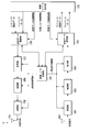
- FIG. 1 is a block diagram showing an example of a terminal device 1 according to the first embodiment of the present invention.
- the terminal device 1 includes a reception unit 101, a demodulation unit 102, a decoding unit 103, a reception data control unit 104, a physical layer control unit 105, a transmission data control unit 106, a coding unit 107, a modulation unit 108, a transmission unit 109, a radio resource It is comprised at least from the control part 110.
- FIG. The “unit” in the figure is an element that realizes the function and each procedure of the terminal device 1 that is also expressed by terms such as section, circuit, component device, device, and unit.
- the radio resource control unit 110 is a block that executes each function of an RRC (Radio Resource Control) layer that performs radio resource control of the terminal device 1.
- the reception data control unit 104 and the transmission data control unit 106 execute functions in a MAC (Medium Access Control) layer, a RLC (Radio Link Control) layer, and a PDCP (Packet Data Convergence Protocol) layer that manage the data link layer. It is a block to do.
- RRC Radio Resource Control
- the reception data control unit 104 and the transmission data control unit 106 execute functions in a MAC (Medium Access Control) layer, a RLC (Radio Link Control) layer, and a PDCP (Packet Data Convergence Protocol) layer that manage the data link layer. It is a block to do.
- MAC Medium Access Control
- RLC Radio Link Control
- PDCP Packet Data Convergence Protocol
- the terminal apparatus 1 receives a plurality of frequencies (frequency bands, frequency bandwidths) by carrier aggregation and / or dual connectivity or reception block (reception) in order to support reception processing in the same subframe of a cell.
- Unit 101, demodulation unit 102, decoding unit 103), and transmission system block (encoding unit 107, modulation) to support transmission processing in the same subframe in a plurality of frequencies (frequency band, frequency bandwidth) or cell
- the configuration may include a plurality of units 108 and transmission units 109).
- the terminal device 1 may be configured to include a plurality of reception data control units 104, physical layer control units 105, transmission data control units 106, and radio resource control units 110 for each corresponding base station device. . That is, the terminal device 1 includes a physical layer, a MAC layer, an RLC layer, and a PDCP layer corresponding to the primary base station device, and a physical layer, a MAC layer, an RLC layer, and a PDCP layer corresponding to the secondary base station device, respectively. But you can. However, even in this case, it is desirable that the terminal device 1 has one RRC layer.
- reception data control information is input from the radio resource control unit 110 to the reception data control unit 104, and physical layer control information that is a control parameter for controlling each block is input to the physical layer control unit 105. Is entered.
- the physical layer control information is information including parameter settings necessary for wireless communication control of the terminal device 1 configured by reception control information and transmission control information.
- the physical layer control information is set by radio connection resource settings, cell-specific broadcast information, system parameters, or the like transmitted individually (dedicated) from the base station apparatus 2 to the terminal apparatus 1, and the radio resource control unit 110 Input to the physical layer control unit 105 as necessary.
- the physical layer control unit 105 appropriately inputs reception control information that is control information related to reception to the reception unit 101, the demodulation unit 102, and the decoding unit 103.
- the reception control information includes information such as reception frequency band information, reception timing related to physical channels and physical signals, multiplexing methods, and radio resource control information as downlink scheduling information.
- the received data control information is downlink control information including secondary cell inactivation timer information, DRX control information, multicast data reception information, downlink retransmission control information, and the like in the MAC layer, RLC layer, and PDCP layer. Control information related to each downlink is included.
- the received signal is received by the receiving unit 101.
- the receiving unit 101 receives a signal from the base station apparatus 2 according to the frequency and frequency band notified by the reception control information.
- the received signal is input to the demodulation unit 102.
- the demodulator 102 demodulates the signal.
- Demodulation section 102 inputs the demodulated signal to decoding section 103.
- Decoding section 103 decodes the input signal, and inputs the decoded data (also referred to as downlink data, downlink control data, and downlink transport block) to reception data control section 104.
- the MAC control element transmitted from the base station apparatus 2 together with each data is also decoded by the decoding unit 103, and related data is input to the reception data control unit 104.
- the reception data control unit 104 controls the physical layer control unit 105 based on the received MAC control element (for example, cell activation / deactivation, DRX control, transmission timing adjustment, etc.) and buffers each decoded data And error correction control (HARQ) of the retransmitted data. For each data input to the reception data control unit 104, related data is input (transferred) to the radio resource control unit 110.
- the received MAC control element for example, cell activation / deactivation, DRX control, transmission timing adjustment, etc.
- HARQ decoded data And error correction control
- transmission data control information is input from the radio resource control unit 110 to the transmission data control unit 106, and the physical layer control unit 105 is a physical layer that is a control parameter for controlling each block. Control information is input.
- the physical layer control unit 105 appropriately inputs transmission control information, which is control information related to transmission, to the encoding unit 107, the modulation unit 108, and the transmission unit 109.
- the transmission control information includes information such as encoding information, modulation information, transmission frequency band information, transmission timing related to physical channels and physical signals, multiplexing method, and radio resource arrangement information as uplink scheduling information.
- the transmission data control information includes DTX control information, random access setting information, uplink shared channel information, logical channel priority information, resource request setting information, cell group information, uplink retransmission control information, power headroom report information, etc. Including uplink control information.
- the radio resource control unit 110 may set a plurality of random access setting information respectively corresponding to a plurality of cells in the transmission data control unit 106.
- the radio resource control unit 110 manages transmission timing adjustment information and a transmission timing timer used for adjustment of uplink transmission timing, and states of uplink transmission timing (transmission for each cell (or for each cell group and for each TA group)). (Timing adjustment state or transmission timing non-adjustment state).
- the transmission timing adjustment information and the transmission timing timer are included in the transmission data control information.
- the transmission data control unit 106 transmits transmission timing adjustment information corresponding to the uplink transmission timing of each of a plurality of cells (or cell groups, TA groups).
- the resource request setting information includes at least maximum transmission counter setting information and radio resource request prohibition timer information.
- the radio resource control unit 110 may set a plurality of resource request setting information respectively corresponding to a plurality of cells in the transmission data control unit 106.
- Transmission data (uplink data and uplink control data, also referred to as an uplink transport block) generated in the terminal device 1 is input from the radio resource control unit 110 to the transmission data control unit 106 at an arbitrary timing. At this time, the transmission data control unit 106 calculates the amount of input transmission data (uplink buffer amount). The transmission data control unit 106 has a function of determining whether the input transmission data is data belonging to the control plane or data belonging to the user plane.
- the transmission data control unit 106 stores the transmission data in an uplink buffer in the transmission data control unit 106 (not shown). Then, the transmission data control unit 106 determines whether radio resources necessary for transmitting the input transmission data are allocated to the terminal device 1. Based on the radio resource allocation, the transmission data control unit 106 receives a radio resource request using a physical uplink shared channel PUSCH, a physical uplink control channel (SR-PUCCH), or a radio resource request using a physical random access channel. Any one is selected, and control processing for transmitting the selected channel is requested to the physical layer control unit 105.
- PUSCH physical uplink shared channel
- SR-PUCCH physical uplink control channel
- the transmission data control unit 106 determines whether or not a trigger condition related to power headroom reporting is satisfied, and for each cell (component carrier) notified from the physical layer when power headroom reporting is triggered.
- the MAC control element used for the power headroom report is generated based on the calculation result of the power headroom.
- the encoding unit 107 appropriately encodes each data according to the transmission control information and inputs the data to the modulation unit 108.
- Modulation section 108 performs appropriate modulation processing based on the channel structure for transmitting each encoded data.
- the transmission unit 109 maps each modulated data to the frequency domain, converts the frequency domain signal into a time domain signal, and amplifies the power on a carrier having a predetermined frequency.
- the transmission unit 109 also adjusts the uplink transmission timing according to the transmission timing adjustment information for each cell (also for each cell group and each TA group) input from the radio resource control unit 110.
- the physical uplink shared channel in which the uplink control data is arranged can include, for example, a layer 3 message (radio resource control message; RRC message) in addition to the user data.
- RRC message radio resource control message
- FIG. 1 other constituent elements of the terminal device 1 and transmission paths of data (control information) between the constituent elements are omitted, but a plurality of other functions necessary for operating as the terminal device 1 are provided. It is clear that this block has as a component. For example, a NAS layer unit that performs control with the core network and an application layer unit exist above the radio resource control unit 110.
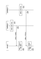
- FIG. 2 is a block diagram showing an example of the base station apparatus 2 according to the first embodiment of the present invention.
- the base station apparatus includes a reception unit 201, a demodulation unit 202, a decoding unit 203, a reception data control unit 204, a physical layer control unit 205, a transmission data control unit 206, a coding unit 207, a modulation unit 208, a transmission unit 209, a radio resource It comprises at least a control unit 210 and a network signal transmission / reception unit 211.
- the “unit” in the figure is an element that executes the functions of the base station apparatus 2 and the procedures, which are also expressed by terms such as section, circuit, component apparatus, device, and unit.
- the radio resource control unit 210 is a block that executes each function of an RRC (Radio Resource Control) layer that performs radio resource control of the base station apparatus 2.
- RRC Radio Resource Control
- the reception data control unit 204 and the transmission data control unit 206 execute functions in a MAC (Medium Access Control) layer, an RLC (Radio Link Control) layer, and a PDCP (Packet Data Convergence Protocol) layer that manage the data link layer. It is a block to do.
- MAC Medium Access Control
- RLC Radio Link Control
- PDCP Packet Data Convergence Protocol
- the base station apparatus 2 receives a plurality of frequencies (frequency band, frequency bandwidth) by carrier aggregation and / or dual connectivity in order to support a reception system block (reception unit 201, demodulation unit 202, decoding unit 203). ), And a plurality of transmission system blocks (encoding unit 207, modulation unit 208, and transmission unit 209).
- the reception data control unit 204, the physical layer control unit 205, the transmission data control unit 206, the radio resource control unit 210, and the network signal transmission / reception unit 211 may be provided.
- the radio resource control unit 210 inputs downlink data and downlink control data to the transmission data control unit 206.
- the transmission data control unit 206 inputs the MAC control element and each data (downlink data or downlink control data) to the encoding unit 207.
- the encoding unit 207 encodes the input MAC control element and each data, and inputs the encoded data to the modulation unit 208.
- Modulation section 208 modulates the encoded signal.
- the transmission unit 209 maps the input signal to the frequency domain, converts the frequency domain signal into a time domain signal, and transmits the signal after performing power amplification on a predetermined frequency carrier wave.
- the physical downlink shared channel in which downlink control data is arranged typically constitutes a layer 3 message (RRC message).
- the receiving unit 201 converts the signal received from the terminal device 1 into a baseband digital signal.
- the receiving unit 201 receives signals at different timings for each cell (also for each cell group and each TA group).
- the digital signal converted by the reception unit 201 is input to the demodulation unit 202 and demodulated.
- the signal demodulated by the demodulator 202 is then input to the decoder 203.
- the decoding unit 203 decodes the input signal and inputs each decoded data (uplink data and uplink control data) to the reception data control unit 204.
- the MAC control element transmitted from the terminal device 1 together with each data is also decoded by the decoding unit 203, and related data is input to the reception data control unit 204.
- the received data control unit 204 buffers the physical layer control unit 205 based on the received MAC control element (for example, control related to power headroom report, control related to buffer status report, etc.), and buffers each decoded data, Error correction control (HARQ) of the retransmitted data is performed. For each data input to the reception data control unit 204, related data is input (transferred) to the radio resource control unit 210.
- the received MAC control element for example, control related to power headroom report, control related to buffer status report, etc.
- the physical layer control information necessary for control of each block is information including parameter settings necessary for radio communication control of the base station apparatus 2 configured by reception control information and transmission control information.
- the physical layer control information is set by a higher-level network device (MME, gateway device (SGW), OAM, etc.) and system parameters, and the radio resource control unit 210 inputs the control unit 204 as necessary.
- the physical layer control unit 205 inputs physical layer control information related to transmission to each block of the encoding unit 207, modulation unit 208, and transmission unit 209 as transmission control information, and receives physical layer control information related to reception as reception control information. Are appropriately input to each block of the receiving unit 201, the demodulating unit 202, and the decoding unit 203.
- the received data control information includes control information related to the uplink of the terminal device 1 for each of the MAC layer, RLC layer, and PDCP layer of the base station device 2.
- the transmission data control information includes control information related to the downlink of the terminal device 1 for each of the MAC layer, RLC layer, and PDCP layer of the base station device 2. That is, the reception data control information and the transmission data control information are set for each terminal device 1.
- the network signal transmission / reception unit 211 transmits (transfers) or receives a control message or user data between the base station devices 2 or between the upper network device (MME, SGW) and the base station device 2.
- MME mobile phone
- SGW network device
- FIG. 2 the components of other base station apparatus 2 and the transmission path of data (control information) between the components are omitted, but other functions necessary for operating as base station apparatus 2 are omitted. It is clear that it has a plurality of blocks as constituent elements. For example, a radio resource management unit and an application layer unit exist above the radio resource control unit 210.
- FIG. 3 shows an example of a sequence chart relating to the secondary cell allocation procedure in the first embodiment of the present invention.
- the terminal apparatus 1 and the base station apparatus 2 are connected using a plurality of cells.
- the base station apparatus 2 includes a base station apparatus 2-1 and a base station apparatus 2-2.
- the base station apparatus 2-1 constitutes a macro cell
- the base station apparatus 2-2 is a base station apparatus 2 that constitutes a small cell, but the configuration of the corresponding cell is not limited.
- the base station apparatus 2-1 which is a master base station apparatus determines the start of communication by dual connectivity. Then, it decides to add the cell (secondary cell group cell) of the base station device 2-2 that is the secondary base station to the terminal device 1, generates a secondary cell group addition message, and transmits it to the base station device 2-2. (Step S100).
- the base station device 2-1 transmits the secondary cell group addition message including the capability information of the terminal device 1 and the cell information to be added.
- the base station apparatus 2-1 can determine a cell to be added based on one or a combination of information such as a measurement event report or CSI report and a cell load status. Also, the base station apparatus 2-1 can determine a cell to be added using information other than this.
- the base station apparatus 2-1 may notify the base station apparatus 2-2 of the secondary cell identifier information (cell index information, cell index number) set in the terminal apparatus 1. By notifying the cell index information of the secondary cell, the base station apparatus 2-2 can assign a cell index number different from the cell index of the cell of the base station apparatus 2-1.
- the base station apparatus 2-1 may notify the base station apparatus 2-2 of the cell index information (cell index number) range of the secondary cell reserved for the terminal apparatus 1.
- the base station apparatus 2-1 notifies that the cell indexes # 1 to # 4 are usable (assignable) and the base station apparatus 2-2 can use the cell indexes # 5 to # 7. Also good.
- cell indexes # 1, # 2, and # 4 can be used in the base station apparatus 2-1, and cell indexes # 3, # 5 to # 7 can be used in the base station apparatus 2-2. You may be notified.
- the base station apparatus 2-2 can assign a cell index number different from the cell index of the cell of the base station apparatus 2-1.
- the base station device 2-2 receives the secondary cell group addition message, and if the specified cell can be set (added) to the terminal device 1, it generates a secondary cell group addition permission message and generates the base station device.
- the data is transmitted to 2-1 (step S101).
- the base station apparatus 2-2 sets radio resources related to at least the cells of the secondary cell group to be added (for example, broadcast information of the secondary cell group, radio resource common settings, random access). Configuration and physical uplink control channel setting information).
- the base station device 2-1 includes the radio resource setting included in the secondary cell group addition permission message in the RRC connection reconfiguration message and transmits it to the terminal device 1 (step S102).
- the RRC connection reconfiguration message includes at least one cell configuration of the secondary cell group to be added.
- the RRC connection reconfiguration message is a layer 3 message, for example, an RRCConnectionReconfiguration message.
- FIG. 4 is a diagram illustrating an example of cell index (cell index number) allocation notified from the base station apparatus 2 to the terminal apparatus 1 in the first embodiment.
- the cell index set in the terminal apparatus 1 is adjusted between the cell groups of each other. (Coordinated). In other words, it is guaranteed that a different cell index is assigned to each of the MCG and SCG cells set in the terminal device 1.
- the primary cell, the secondary cell # 1, and the secondary cell # 2 are set as the MCG cells, and the secondary cell # 3 and the secondary cell # 4 are set as the SCG cells.
- Secondary cell # 3 is a primary secondary cell.
- the cell index # 0 for the primary cell the cell index # 1 for the secondary cell # 1
- the cell index # 2 for the secondary cell # 2 the cell index # 3
- cell index # 4 is set for secondary cell # 4.
- the cell index # 0 is assigned statically (static, fixed) as the cell index of the primary cell.
- the base station apparatus 2 may statically assign the cell index # 1 instead of individually assigning the cell index of the primary secondary cell for each terminal apparatus 1. That is, in dual connectivity, cell index # 0 and cell index # 1 can be regarded as reserved in advance for the primary cell and the primary secondary cell, respectively.
- the base station device 2 may not explicitly notify the terminal device 1 of the cell index number of the primary secondary cell.
- the terminal device 1 may perform control by regarding the SCG cell to which the cell index # 1 is assigned as the primary secondary cell.
- the terminal device 1 when reporting the PH related to the secondary cell, the terminal device 1 needs to include the cell index number in the first octet.
- the terminal device 1 can use the conventional report format (format) as much as possible. The overhead can be reduced.
- FIG. 5 is an example of a sequence chart diagram showing a procedure for reporting power headroom.
- the RRC connection reconfiguration message in step S201 in FIG. 5 is an RRC connection reconfiguration message instructing addition of a cell of the secondary cell group in step S102 in FIG.
- the terminal device 1 receives the RRC connection reconfiguration message, and adds the cell (secondary cell group) of the base station device 2-2 according to the setting information of the secondary cell group included in the RRC connection reconfiguration message (step S202). At this time, the MAC layer, RLC layer, and PDCP layer corresponding to the base station apparatus 2-2 are also set (established).
- the added cell includes at least a primary secondary cell.
- the terminal device 1 to which the primary secondary cell has been added triggers a power headroom report (step S203).
- the power headroom report is triggered when a MAC layer corresponding to the secondary base station device (base station device 2-2) is newly established in the terminal device 1.
- the terminal device 1 uses the primary cell of the MCG before adding the cell of the secondary cell group, the secondary cell in which the MCG is activated, if set, and the primary secondary cell. , At least included in the MAC control element.
- the terminal device 1 transmits an RRC connection reconfiguration completion message to the base station device 2-1.
- the RRC connection reconfiguration completion message is a layer 3 message, for example, an RRCConnectionReconfigurationComplete message.
- the terminal device 1 may transmit the power headroom triggered in step S203 by being included in the RRC connection reconfiguration completion message or transmitted based on subsequent uplink resource allocation (uplink grant). May be reported to the base station apparatus 2-1 through the physical uplink shared data channel.
- the terminal device 1 transmits the power headroom triggered in step S203 to the base station device 2-2 by the physical uplink shared data channel (message 3) transmitted in the random access procedure in the primary secondary cell. Alternatively, it may be reported to the base station apparatus 2-2 by a physical uplink shared data channel transmitted based on subsequent uplink resource allocation (uplink grant).
- the physical uplink shared data channel (message 3) transmitted in the random access procedure in the primary secondary cell.
- uplink grant uplink resource allocation
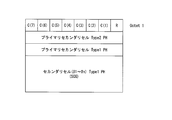
- FIG. 6 is a diagram for explaining a report format of the power headroom of the SCG cell transmitted from the terminal apparatus 1 to the base station apparatus 2 (base station apparatus 2-1 and base station apparatus 2-2).
- Each line in FIG. 6 corresponds to one octet length (8 bits).
- the terminal device 1 may report the nominal power (referred to as Pcmax) of the cell together with the report of the power headroom of each cell.
- the terminal device 1 may not set bits in the bitmap information field (C (i)) of the cell index corresponding to the primary secondary cell in FIG. That is, when the cell index of the secondary cell reporting the power headroom is set to “1”, the bitmap information field (C (i)) of the cell index corresponding to the primary secondary cell is set to “0”. May be.
- C (3) may be set to “0” even when cell index # 3 is set as the cell index corresponding to the primary secondary cell.
- the terminal device 1 may regard the bit of the bit map information field (C (i)) corresponding to the primary secondary cell in FIG. 6 as the reserved bit (R).
- the terminal device 1 When the power headroom is triggered in the communication by dual connectivity, the terminal device 1 replaces the MAC control element (FIG. 13) of the conventional power headroom report with the power headroom report including the type 2PH of the secondary primary cell.
- MAC control element (FIG. 6) is generated, and is placed (included) in the MAC PDU and transmitted.
- the base station apparatus 2 receives the MAC PDU transmitted from the terminal apparatus 1 in the communication by dual connectivity, and considers that the MAC control element including the secondary primary cell type 2PH is arranged in the MAC PDU. Receive.
- FIG. 7 is an example of a sequence chart showing a procedure for cell activation / inactivation.
- FIG. 7 is started from a state in which the MCG cell of the base station device 2-1 and the SCG cell of the base station device 2-2 are set for the terminal device 1 by dual connectivity.
- the base station apparatus 2-1 controls activation and / or deactivation of secondary cells among the MCG cells set in the terminal apparatus 1.
- the base station apparatus 2-2 notifies activation and / or deactivation of the secondary cell among the SCG cells set in the terminal apparatus 1. That is, the base station apparatus 2-1 that manages the MCG cell does not control activation and / or deactivation of the secondary cell of the base station apparatus 2-2 that manages the SCG cell.
- the base station apparatus 2-2 that manages the SCG cell does not control activation and / or deactivation of the secondary cell of the base station apparatus 2-1 that manages the MCG cell.
- the terminal device 1 controls the cell state only for the secondary cell (including the primary secondary cell) of the cell group to which the received cell belongs. In other words, it is only necessary to consider only the bit of the cell index corresponding to the cell group among the cell indexes included in the MAC control element indicating activation / deactivation.
- the base station apparatus 2-1 determines a cell to be activated and / or deactivated from the MCG cells in step S300. At this time, the base station apparatus 2-1 may not consider the state of the SCG cell in the base station apparatus 2-2.
- the base station device 2-1 generates a MAC control element (Activation / Deactivation MAC-CE) indicating activation / deactivation, and transmits it to the terminal device 1 (step S301).
- the base station apparatus 2-1 can use the format shown in FIG. 13 as a MAC control element indicating activation / deactivation.
- the terminal apparatus 1 When receiving the MAC control element indicating activation / deactivation from the base station apparatus 2-1, the terminal apparatus 1 regards only the secondary cell belonging to the MCG as a cell to be activated / deactivated. Control (processing) is performed (step S302). That is, the terminal device 1 uses the secondary index set as the MCG cell for the terminal device 1 in the cell index information field in the MAC control element indicating activation / deactivation received from the base station device 2-1. Activation / deactivation is controlled according to the cell index information field corresponding to the cell.
- the terminal device 1 may ignore the cell index information field other than the cell index information field corresponding to the secondary cell set as the MCG cell, or may regard it as a reserved bit.
- the terminal device 1 may ignore the cell index information field corresponding to the secondary cell set as the SCG cell, or may regard it as a reserved bit.
- the base station device activates the secondary cell # 1 and changes the secondary cell # 2 to an inactivated state.
- 2-1 sets “1 (activation)” in C (1) and “0 (inactivation)” in C (2) for transmission in the C (i) field. Since C (3) to C (7) are not considered (or ignored) by the terminal device 1, either “0” or “1” may be set, but “0” is used for debugging or the like.
- "Or” 1 "is desirably set in a unified manner.
- the base station apparatus 2-2 determines a cell to be activated and / or deactivated from the SCG cells.
- the base station apparatus 2-2 may not consider the state of the MCG cell in the base station apparatus 2-1.
- the base station device 2-2 generates a MAC control element indicating activation / deactivation and transmits it to the terminal device 1 (step S304).
- the base station apparatus 2-2 can use the format shown in FIG. 11 as a MAC control element indicating activation / deactivation.
- the terminal apparatus 1 When receiving the MAC control element indicating activation / deactivation from the base station apparatus 2-2, the terminal apparatus 1 regards only the secondary cells belonging to the SCG as the cells to be activated / deactivated. Then, control (processing) is performed (step S305). That is, the terminal device 1 has the secondary set as the SCG cell for the terminal device 1 in the cell index information field in the MAC control element indicating activation / deactivation received from the base station device 2-2. Activation / deactivation is controlled according to the cell index information field corresponding to the cell.
- the terminal device 1 may ignore the cell index information field other than the cell index information field corresponding to the secondary cell set as the SCG cell, or may regard it as a reserved bit.
- the terminal device 1 may ignore the cell index information field corresponding to the secondary cell set as the MCG cell, or may regard it as a reserved bit.
- the base station device 2-2 sets the C (i) field.
- “1 (activation)” is set in C (4) and transmitted. Since C (1) to C (2) and C (5) to C (7) are not considered (or ignored) by the terminal device 1, either “0” or “1” may be set. For the purpose of debugging or the like, it is desirable that the data is transmitted uniformly to either “0” or “1”.
- the cell index corresponding to the primary secondary cell (cell index # 3 (C (3)) in the example of FIG. 4) may always be set to “1”, and the primary secondary cell is always activated. Therefore, the terminal device 1 may ignore the cell index information field corresponding to the primary secondary cell without considering the cell index information field, or may regard it as a reserved bit. When the terminal apparatus 1 does not consider the cell index information field corresponding to the primary secondary cell, the base station apparatus 2-2 may set “0” to the cell index corresponding to the primary secondary cell.
- step 7 may be performed independently of steps S300 to S302 and steps S303 to S305.
- the procedure from step S303 to step S305 may be started before or during the procedure from step S300 to step S302.
- the base station device 2 When adding the SCG cell, the base station device 2 includes the cell index number corresponding to the SCG cell to be added in the configuration (configuration) of the SCG cell and notifies the terminal device 1 of it. As described above, the base station apparatus 2 can also implicitly assign a designated cell index number (for example, cell index # 1) by not explicitly notifying the cell index number of the primary secondary cell. It is.
- a designated cell index number for example, cell index # 1
- the base station apparatus 2 explicitly or implicitly designates the cell index number of the SCG cell to change the SCG cell setting and / or delete (release) the SCG cell setting. Can be notified to the terminal device 1. An instruction to add, change, or delete the setting of the SCG cell to the terminal device 1 is notified using an RRC message.
- the base station apparatus 2 When the base station apparatus 2 releases the primary secondary cell of the terminal apparatus 1 and an SCG cell other than the primary secondary cell is set as the secondary cell for the terminal apparatus 1, the base station apparatus 2 The release may be notified including the cell index number and all the cell index numbers of SCG cells other than the primary secondary cell, or the release may be notified including only the cell index number of the primary secondary cell of the terminal device 1. Good.
- the terminal device 1 When the terminal device 1 receives information in which cell index information (cell index list) indicating one or a plurality of release target SCG cells is set from the base station device 2, the terminal device 1 sets the SCG cell of the corresponding terminal device 1. Release. Further, when the cell index information indicating the SCG cell to be released corresponds to the primary secondary cell, the terminal device 1 is configured for all SCG cells even if SCG cells other than the primary secondary cell are set. It may be considered that the release has been notified.
- cell index information cell index list
- the terminal apparatus 1 and the base station apparatus 2 exchange (exchange and share) cell index information regarding the secondary cell between the base station apparatus 2-1 and the base station apparatus 2-2. Therefore, the problem that the cell index number of the secondary cell assigned to the terminal device 1 is adjusted and the same cell index number is assigned to the same terminal device can be avoided.
- the terminal device 1 can perform power headroom reporting using the notified cell index number regarding the MCG cell and the SCG cell in dual connectivity. Moreover, the base station apparatus 2 of this embodiment can perform activation / deactivation control using the set cell index number for the MCG cell and the SCG cell during dual connectivity.
- the terminal device 1 includes control means for appropriately changing the cell state of the received cell group according to the MAC control element that instructs activation and / or deactivation of the secondary cell. Therefore, the cell state can be controlled efficiently.
- the terminal device 1 since the terminal device 1 includes a control unit that reports a type 1 or type 2 power headroom using one MAC control element for each cell corresponding to the notified cell index number, it is efficient. Can report cell status.
- the terminal device 1 since the terminal device 1 includes a control unit that uses the cell index to set the radio resource setting of each cell corresponding to the notified cell index number, the terminal device 1 can efficiently manage the radio resource setting of the SCG cell. .
- the base station apparatus 2 since the base station apparatus 2 includes a control unit that avoids duplication of cell indexes between the base station apparatuses 2 by exchanging (adjusting) the cell index information between the base station apparatuses 2, the cell station information can be efficiently stored. You can control the state.
- the second embodiment shows a control method in which the terminal device 1 can appropriately perform control even when the same cell index number is set in the terminal device 1.
- the configurations of the terminal device 1 and the base station device 2 of the second embodiment may be the same as those of the first embodiment, description thereof is omitted.
- FIG. 8 is a diagram illustrating an example of allocation of cell indexes (cell index numbers) notified from the base station apparatus 2 to the terminal apparatus 1 in the second embodiment. Unlike the first embodiment, it is not necessary to exchange cell index information between the base station apparatus 2-1 and the base station apparatus 2-2 in advance, and as a result, the cell index set in the terminal apparatus 1 is There may be duplicates.
- the primary cell, the secondary cell # 1, and the secondary cell # 2 are set as the MCG cells, and the secondary cell # 3 and the secondary cell # 4 are set as the SCG cells.
- Secondary cell # 3 is a primary secondary cell.
- cell index # 0 is statically assigned as the cell index of the primary cell.
- the base station apparatus 2 may assign the cell index number statically instead of individually assigning the cell index of the primary secondary cell for each terminal apparatus 1, and the control method in that case is the first implementation.
- the form is the same.
- FIG. 9 illustrates a report format of the power headroom of the SCG cell transmitted from the terminal apparatus 1 to the base station apparatus 2 (base station apparatus 2-1 and base station apparatus 2-2) in the second embodiment.
- the terminal device 1 may follow the procedure described with reference to FIG. 5 as the timing at which the power headroom is triggered.
- Each line in FIG. 9 corresponds to one octet length (8 bits).
- Field, primary secondary cell type 2PH field, primary secondary cell type 1PH field, and activated SCG secondary cell type 1PH field are arranged in the order shown in FIG.
- the MAC control element is generated, and the generated MAC control element is transmitted to the base station apparatus 2 to report the power headroom.
- the terminal device 1 may report the nominal power (referred to as Pcmax) of the cell together with the report of the power headroom of each cell.
- the terminal device 1 includes the field (C (i)) of the bitmap information of the cell index corresponding to the primary secondary cell in FIG.
- the bit need not be set.
- the bitmap information field (C (i)) of the cell index corresponding to the primary secondary cell may be set to “0”. For example, even if cell index # 3 is set as the cell index corresponding to the primary secondary cell, “0” may be set in C (3).
- the terminal device 1 includes a bit in the bitmap information field (C (i)) of the cell index corresponding to the primary secondary cell, and further displays the report value of the primary secondary cell type 1PH as the primary secondary cell type. It is included in the 1PH field and the type 1PH field of the activated secondary cell.
- the terminal device 1 when reporting of the power headroom is triggered, when the secondary cell # 3 (primary secondary cell, cell index # 1) and the secondary cell # 4 (cell index # 2) are activated, the terminal device 1 sets “1” to the bits of C (1) and C (2) in the bit map information field of the cell index in FIG. 9, and sets the bits of C (3) to C (7). Sets “0”. Also, the type 2PH value of cell index # 1 is included in the type 2PH field of the primary secondary cell, and the type 1PH value of cell index # 1 is included in the type 1PH field of the primary secondary cell.
- the type 1PH value of the cell index # 1 and the type 1PH value of the cell index # 2 are sequentially included in the type 1PH field of the activated secondary cell. That is, in this case, the type 1PH of the primary secondary cell is reported by being included in two different fields within the same MAC control element.
- the terminal apparatus 1 reports to the base station apparatus 2 a set of the SCG cell power headroom report format shown in FIG. 9 and the MCG cell power headroom report format shown in FIG. That is, the terminal device 1 generates the MAC control element of the power headroom report of the MCG cell and the MAC control element of the power headroom report of the SCG cell, respectively, when the power headroom is triggered in the communication by dual connectivity.
- These two MAC control elements are each placed in a MAC PDU and transmitted. It is desirable that each MAC control element is continuously arranged in the MAC PDU.
- the base station device 2 receives the MAC PDU transmitted from the terminal device 1 in communication by dual connectivity, and when two MAC control elements for power headroom reporting are arranged in the MAC PDU, the MCG
- the MAC control element of the cell power headroom report and the MAC control element of the SCG cell power headroom report are regarded as being arranged (determined), and each power headroom is received.
- the conventional report format can be reused. For example, changes in the MAC layer are minimized, but the MAC header corresponding to the MAC control element is added to the MAC PDU. Since two are included, overhead for the MAC header occurs. Therefore, the terminal device 1 may report the power headroom report of the MCG cell and the power headroom report of the SCG cell by including them in one MAC control element.
- FIG. 10 is a diagram for explaining a report format when the terminal device 1 includes the power headroom report of the MCG cell and the power headroom report of the SCG cell in one MAC control element.
- the first field in FIG. 10 includes a power headroom report regarding the MCG cell, and the latter field includes a power headroom report regarding the SCG cell. Detailed information included in each field follows the description shown in FIG. 9 and FIG.
- the base station device 2-1 and the base station device 2-2 can set the cell index in the terminal device 1 without adjusting between the base station devices 2,
- the cell index number of the primary secondary cell may be statically assigned.
- the base station device 2 may statically assign the cell index # 0 to the terminal device 1 as the cell index number of the primary secondary cell. That is, in dual connectivity, cell index # 0 can be regarded as reserved in advance for the primary cell and the primary secondary cell.
- the base station device 2 may not explicitly notify the terminal device 1 of the cell index number of the primary secondary cell.
- the terminal device 1 may perform control by regarding the MCG cell to which the cell index # 0 is assigned as the primary cell. Moreover, the terminal device 1 may perform control by regarding the SCG cell to which the cell index # 0 is assigned as the primary secondary cell.
- the terminal device 1 controls a cell state only about the secondary cell of the cell group to which the received cell belongs. In other words, it is only necessary to consider only the bit of the cell index corresponding to the cell group among the cell indexes included in the MAC control element indicating activation / deactivation.
- the terminal device 1 and the base station device 2 set the static index (# 0) as the cell index number of the primary secondary cell, thereby setting the cell index C included in the MAC control element indicating activation / deactivation. (I) Since it becomes unnecessary to consider the activation / inactivation of the primary secondary cell by the field, the control becomes simple.
- the base station device 2-1 and the base station device 2-2 can set the cell index in the terminal device 1 without adjusting between the base station devices 2,
- the cell index number of the primary secondary cell may be statically assigned.
- the base station device 2 may statically assign the cell index # 0 to the terminal device 1 as the cell index number of the primary secondary cell. That is, in dual connectivity, cell index # 0 can be regarded as reserved in advance for the primary cell and the primary secondary cell.
- the base station device 2 may not explicitly notify the terminal device 1 of the cell index number of the primary secondary cell.
- the terminal device 1 may perform control by regarding the MCG cell to which the cell index # 0 is assigned as the primary cell. Moreover, the terminal device 1 may perform control by regarding the SCG cell to which the cell index # 0 is assigned as the primary secondary cell.
- the terminal device 1 and the base station device 2 can use the power head using the cell index from the terminal device 1 even when the same cell index number is assigned to the same terminal device. It becomes possible to appropriately control room activation and cell activation / inactivation using the cell index for the terminal device 1.
- the terminal device 1 can perform power headroom reporting using the notified cell index number regarding the MCG cell and the SCG cell in dual connectivity. Moreover, the base station apparatus 2 of this embodiment can perform activation / deactivation control using the set cell index number for the MCG cell and the SCG cell during dual connectivity.
- the terminal device 1 includes control means for appropriately changing the cell state of the received cell group according to the MAC control element that instructs activation and / or deactivation of the secondary cell. Therefore, the cell state can be controlled efficiently.
- the terminal device 1 since the terminal device 1 includes a control unit that reports the type 1 or type 2 power headroom using the MAC control element for each cell group for each cell corresponding to the notified cell index number, the efficiency is improved. Cell status can be reported.
- the terminal device 1 includes a control unit that uses the cell index to set the radio resource setting of each cell corresponding to the notified cell index number, the terminal device 1 can efficiently manage the radio resource setting of the SCG cell. .
- the base station device 2 does not need to exchange (adjust) the cell index information between the base station devices 2 in advance, so that the cell state can be controlled efficiently.
- the uplink transmission scheme can be applied to both communication systems of the FDD (frequency division duplex) scheme and the TDD (time division duplex) scheme.
- the names of the parameters shown in the embodiments are called for convenience of explanation, and even if the parameter names actually applied and the parameter names of the embodiments of the present invention are different, the present invention It does not affect the gist of the invention claimed in the embodiment.
- connection used in each embodiment is not limited to a configuration in which a certain device and another certain device are directly connected using a physical line, and is logically connected. And a configuration in which wireless connection is performed using a wireless technology.
- the terminal device 1 is not only a portable or movable mobile station device, but also a stationary or non-movable electronic device installed indoors or outdoors, such as a mobile phone, a personal computer, a tablet terminal, Communication functions such as AV equipment, kitchen equipment, cleaning / washing equipment, air conditioning equipment, office equipment, vending machines, other life equipment and measuring equipment, in-vehicle devices, wearable equipment and healthcare equipment that can be worn Includes everything on board. Further, the terminal device 1 is not only for person-to-person or person-to-device communication, but also for device-to-device communication (Machine Type Communication, machine type communication) and device-to-device communication (Device to Device Communication; D2D). Used.
- the terminal device 1 is also referred to as a user terminal, a mobile station device, a communication terminal, a mobile device, a terminal, a UE (User Equipment), and an MS (Mobile Station).
- the base station apparatus 2 is also referred to as a radio base station apparatus, a base station, a radio base station, a fixed station, an NB (NodeB), an eNB (evolved NodeB), a BTS (Base Transceiver Station), and a BS (Base Station).
- the base station apparatus 2 is referred to as NB in UMTS defined by 3GPP, and is referred to as eNB in EUTRA and Advanced EUTRA.
- the terminal device 1 in UMTS, EUTRA, and Advanced EUTRA defined by 3GPP is referred to as a UE.
- each part of the terminal device 1 and the base station device 2 or a part of these functions are realized by using the functional block diagram of the terminal device 1 and the base station device 2 of the embodiment.
- the method, means, or algorithm steps of have been described, they can be directly embodied in hardware, software modules executed by a processor, or a combination of the two.
- the terminal device 1 and the base station device 2 have displays other than the configuration of the block diagram described above, such as a power supply device that supplies power to the terminal device 1 and the base station device 2, a battery, a liquid crystal display, etc. It may be configured by a device, a display driving device, a memory, an input / output interface and input / output terminal, a speaker, and other peripheral devices.
- Computer-readable media includes both communication media and computer recording media including media that facilitate carrying a computer program from one place to another.
- One or more instructions or codes are recorded on a computer-readable recording medium, and one or more instructions or codes recorded on the recording medium are read into a computer system and executed, thereby executing the terminal device 1 or the base.
- the station device 2 may be controlled.
- the “computer system” includes an OS and hardware such as peripheral devices.
- a program that operates in the terminal device 1 and the base station device 2 according to each embodiment of the present invention is a program that controls a CPU or the like (a computer is installed) so as to realize the functions of the above-described embodiments according to each embodiment of the present invention.
- Program to function Information handled by these devices is temporarily stored in the RAM at the time of processing, then stored in various ROMs and HDDs, read out by the CPU, and corrected and written as necessary.
- the “computer-readable recording medium” refers to a semiconductor medium (eg, RAM, nonvolatile memory card, etc.), an optical recording medium (eg, DVD, MO, MD, CD, BD, etc.), a magnetic recording medium (eg, , A magnetic tape, a flexible disk, etc.) and a storage device such as a disk unit built in a computer system.
- the “computer-readable recording medium” means that a program is dynamically held for a short time, like a communication line when a program is transmitted via a network such as the Internet or a communication line such as a telephone line. In this case, it is intended to include those that hold a program for a certain period of time, such as a volatile memory inside a computer system serving as a server or a client in that case.
- the above program may be for realizing a part of the above-described functions, and further, the above-described functions may be realized in combination with a program already recorded in a computer system. Good.
- each functional block or various features of the terminal device 1 and the base station device 2 used in each of the above embodiments is a general-purpose processor, a digital signal processor designed to execute the functions described in this specification. (DSP), application specific or general purpose integrated circuit (ASIC), field programmable gate array signal (FPGA), or other programmable logic device, discrete gate or transistor logic, discrete hardware components, or combinations thereof It can be implemented or implemented by something.
- DSP digital signal processor
- ASIC application specific or general purpose integrated circuit
- FPGA field programmable gate array signal
- FPGA field programmable gate array signal
- the general purpose processor may be a microprocessor, but alternatively the processor may be a conventional processor, controller, microcontroller, or state machine.
- the general-purpose processor or each circuit described above may be configured by a digital circuit, may be configured by an analog circuit, or may be configured by combining a digital circuit and an analog circuit.
- the processor may be implemented as a combination of computing devices.
- a DSP and a microprocessor for example, a DSP and a microprocessor, a plurality of microprocessors, one or more microprocessors connected to a DSP core, or a combination of other such configurations.
- Some aspects of the present invention can be applied to a terminal device, a base station device, a communication system, a control method, an integrated circuit, and the like that need to efficiently control the state of a plurality of cells.
Abstract
Priority Applications (4)
| Application Number | Priority Date | Filing Date | Title |
|---|---|---|---|
| US15/123,267 US9883467B2 (en) | 2014-03-06 | 2015-03-05 | Terminal device, base station device, communication system, control method, and integrated circuit |
| CN201580012263.7A CN106105301B (zh) | 2014-03-06 | 2015-03-05 | 终端装置、基站装置、通信系统、控制方法 |
| JP2016506555A JP6503616B2 (ja) | 2014-03-06 | 2015-03-05 | 端末装置、基地局装置、および制御方法 |
| EP15758344.4A EP3116259B1 (fr) | 2014-03-06 | 2015-03-05 | Dispositif de terminal, dispositif de station de base, système de communications, procédé de commande et circuit intégré |
Applications Claiming Priority (2)
| Application Number | Priority Date | Filing Date | Title |
|---|---|---|---|
| JP2014043684 | 2014-03-06 | ||
| JP2014-043684 | 2014-03-06 |
Publications (1)
| Publication Number | Publication Date |
|---|---|
| WO2015133579A1 true WO2015133579A1 (fr) | 2015-09-11 |
Family
ID=54055379
Family Applications (1)
| Application Number | Title | Priority Date | Filing Date |
|---|---|---|---|
| PCT/JP2015/056532 WO2015133579A1 (fr) | 2014-03-06 | 2015-03-05 | Dispositif de terminal, dispositif de station de base, système de communications, procédé de commande et circuit intégré |
Country Status (5)
| Country | Link |
|---|---|
| US (1) | US9883467B2 (fr) |
| EP (1) | EP3116259B1 (fr) |
| JP (1) | JP6503616B2 (fr) |
| CN (1) | CN106105301B (fr) |
| WO (1) | WO2015133579A1 (fr) |
Cited By (2)
| Publication number | Priority date | Publication date | Assignee | Title |
|---|---|---|---|---|
| JP2017515341A (ja) * | 2014-03-21 | 2017-06-08 | アルカテル−ルーセント | 二重接続においてphrを拡張するための方法および装置 |
| CN113596973A (zh) * | 2019-02-02 | 2021-11-02 | 大唐移动通信设备有限公司 | Scg状态控制方法、装置、ue、mn、sn及介质 |
Families Citing this family (19)
| Publication number | Priority date | Publication date | Assignee | Title |
|---|---|---|---|---|
| KR20150020018A (ko) * | 2013-08-14 | 2015-02-25 | 삼성전자주식회사 | 이동 통신 시스템에서 복수의 캐리어를 이용하는 데이터 송수신 방법 및 장치 |
| CN107567718B (zh) * | 2015-03-06 | 2021-03-09 | 三星电子株式会社 | 在移动通信系统中由配置有多个载波的用户设备执行和报告测量的方法和装置 |
| EP3510805B1 (fr) * | 2016-09-28 | 2020-07-29 | Huawei Technologies Co., Ltd. | Dispositif et procédé de configuration de gestion des ressources radio |
| WO2018175252A1 (fr) * | 2017-03-23 | 2018-09-27 | Interdigital Patent Holdings, Inc. | Commande de puissance basée sur l'affaiblissement de propagation en altitude pour véhicules aériens |
| CN108811128B (zh) * | 2017-05-05 | 2021-02-05 | 华为技术有限公司 | 一种功率控制方法及终端设备 |
| BR112019026781A2 (pt) * | 2017-06-16 | 2020-06-30 | Nokia Technologies Oy | aparelho, equipamento de usuário, método e memória lida por computador |
| KR102450189B1 (ko) * | 2017-09-15 | 2022-09-30 | 광동 오포 모바일 텔레커뮤니케이션즈 코포레이션 리미티드 | 스케줄링 요청의 구성 방법, 단말 기기 및 컴퓨터 저장 매체 |
| CN111418225B (zh) * | 2017-09-20 | 2022-04-15 | 三星电子株式会社 | 无线通信系统中发送和接收数据的方法及装置 |
| CN110731103A (zh) * | 2017-11-16 | 2020-01-24 | Oppo广东移动通信有限公司 | 上报phr的方法、终端设备和基站 |
| US10674518B2 (en) * | 2017-12-27 | 2020-06-02 | Comcast Cable Communications, Llc | Dynamic management of interference and coverage in wireless communications |
| CN111278112B (zh) * | 2018-12-05 | 2023-03-24 | 华为技术有限公司 | 一种功率余量的上报方法及装置 |
| CN111314906A (zh) * | 2018-12-11 | 2020-06-19 | 夏普株式会社 | 用户设备及其方法、基站及其方法 |
| JP7273859B2 (ja) * | 2019-02-01 | 2023-05-15 | 株式会社Nttドコモ | ユーザ装置及び基地局装置 |
| WO2021026906A1 (fr) * | 2019-08-15 | 2021-02-18 | 华为技术有限公司 | Procédé de communication, appareil de communication, support d'informations informatique et système de communication |
| CN115243393A (zh) * | 2020-03-12 | 2022-10-25 | 展讯通信(上海)有限公司 | 辅小区组的状态控制方法及装置、存储介质、ue、基站 |
| US11310815B2 (en) | 2020-07-14 | 2022-04-19 | Sprint Communications Company L.P. | Wireless data communication service over multiple uplinks |
| WO2022109955A1 (fr) * | 2020-11-26 | 2022-06-02 | Oppo广东移动通信有限公司 | Procédé et appareil d'indication d'informations, dispositif terminal et dispositif de réseau |
| EP4324244A1 (fr) * | 2021-04-13 | 2024-02-21 | Lenovo (Beijing) Limited | Procédés et appareils destinés à sauvegarder et à déclarer des informations se rapportant à une procédure de changement de pscell |
| CN115589621A (zh) * | 2021-07-06 | 2023-01-10 | 中国移动通信有限公司研究院 | 一种条件主辅小区添加或改变的方法、装置和存储介质 |
Citations (2)
| Publication number | Priority date | Publication date | Assignee | Title |
|---|---|---|---|---|
| US20120178494A1 (en) * | 2011-01-07 | 2012-07-12 | Interdigital Patent Holdings, Inc. | Methods, apparatus and systems for handling additional power backoff |
| JP2012169913A (ja) * | 2011-02-15 | 2012-09-06 | Sharp Corp | 通信システム、基地局装置、移動局装置、パワーヘッドルーム報告方法および集積回路 |
Family Cites Families (13)
| Publication number | Priority date | Publication date | Assignee | Title |
|---|---|---|---|---|
| US8311014B2 (en) * | 2009-11-06 | 2012-11-13 | Telefonaktiebolaget L M Ericsson (Publ) | Virtual care-of address for mobile IP (internet protocol) |
| CN101778416B (zh) * | 2010-02-10 | 2015-05-20 | 中兴通讯股份有限公司 | 功率上升空间的测量和报告方法及终端 |
| WO2011159123A2 (fr) * | 2010-06-17 | 2011-12-22 | Pantech Co., Ltd. | Appareil et procédé d'émission d'informations de puissance dans un système à composantes porteuses multiples |
| DK2583506T3 (en) * | 2010-06-18 | 2015-04-27 | Ericsson Telefon Ab L M | METHODS FOR PROVIDING POWER RESERVE REPORTS LOCATED IN ORDER OF COMPONENT CARRIER INDEXES AND RELATED WIRELESS TERMINALS and base stations |
| CN102316569B (zh) * | 2010-06-29 | 2015-05-20 | 中兴通讯股份有限公司 | 一种用于载波聚合场景下的phr上报方法和系统 |
| CN102104905B (zh) * | 2010-08-13 | 2014-02-05 | 电信科学技术研究院 | 载波聚合场景下的功率余量上报方法和设备 |
| KR101276853B1 (ko) * | 2010-08-17 | 2013-06-18 | 엘지전자 주식회사 | 멀티캐리어를 지원하는 통신 시스템에서 파워 헤드룸 리포트를 전송하는 방법 및 장치 |
| CN102448160B9 (zh) * | 2010-09-30 | 2016-06-15 | 中兴通讯股份有限公司 | 载波聚合场景下上报功率上升空间报告的方法和装置 |
| US20130215866A1 (en) * | 2010-11-05 | 2013-08-22 | Jae Hyun Ahn | Apparatus and method for transmitting power information about component carrier in multiple component carrier system |
| CN102123437B (zh) * | 2011-03-03 | 2016-02-17 | 电信科学技术研究院 | 功率余量上报和调度子帧的方法、系统及设备 |
| WO2012119626A1 (fr) * | 2011-03-08 | 2012-09-13 | Panasonic Corporation | Signalement de différences de retards de propagation pour des porteuses à composantes multiples |
| KR102040883B1 (ko) * | 2012-08-23 | 2019-11-05 | 인터디지탈 패튼 홀딩스, 인크 | 무선 시스템에서의 다중 스케줄러들을 이용한 동작 |
| US20150358920A1 (en) * | 2013-01-14 | 2015-12-10 | Telefonaktiebolaget L M Ericsson (Publ) | Handling uplink transmit power reporting |
-
2015
- 2015-03-05 WO PCT/JP2015/056532 patent/WO2015133579A1/fr active Application Filing
- 2015-03-05 CN CN201580012263.7A patent/CN106105301B/zh active Active
- 2015-03-05 JP JP2016506555A patent/JP6503616B2/ja active Active
- 2015-03-05 EP EP15758344.4A patent/EP3116259B1/fr active Active
- 2015-03-05 US US15/123,267 patent/US9883467B2/en active Active
Patent Citations (2)
| Publication number | Priority date | Publication date | Assignee | Title |
|---|---|---|---|---|
| US20120178494A1 (en) * | 2011-01-07 | 2012-07-12 | Interdigital Patent Holdings, Inc. | Methods, apparatus and systems for handling additional power backoff |
| JP2012169913A (ja) * | 2011-02-15 | 2012-09-06 | Sharp Corp | 通信システム、基地局装置、移動局装置、パワーヘッドルーム報告方法および集積回路 |
Non-Patent Citations (4)
| Title |
|---|
| ITL INC.: "Discussion on New LCID for DC PHR MAC CE", 3GPP TSG RAN WG2 MEETING #87BIS R2-144171, 26 September 2014 (2014-09-26), XP050870182 * |
| SAMSUNG: "Power headroom report for dual connectivity", 3GPP TSG RAN WG2 #85B R2-141478, 21 March 2014 (2014-03-21), XP050792649 * |
| SAMSUNG: "Power headroom report for inter-ENB CA", 3GPP TSG RAN WG2 #84 R2-133823, XP050736668 * |
| See also references of EP3116259A4 * |
Cited By (3)
| Publication number | Priority date | Publication date | Assignee | Title |
|---|---|---|---|---|
| JP2017515341A (ja) * | 2014-03-21 | 2017-06-08 | アルカテル−ルーセント | 二重接続においてphrを拡張するための方法および装置 |
| CN113596973A (zh) * | 2019-02-02 | 2021-11-02 | 大唐移动通信设备有限公司 | Scg状态控制方法、装置、ue、mn、sn及介质 |
| CN113596973B (zh) * | 2019-02-02 | 2023-04-07 | 大唐移动通信设备有限公司 | Scg状态控制方法、装置、ue、mn、sn及介质 |
Also Published As
| Publication number | Publication date |
|---|---|
| CN106105301B (zh) | 2019-11-08 |
| EP3116259A4 (fr) | 2017-09-27 |
| US9883467B2 (en) | 2018-01-30 |
| US20170078984A1 (en) | 2017-03-16 |
| JPWO2015133579A1 (ja) | 2017-04-06 |
| JP6503616B2 (ja) | 2019-04-24 |
| CN106105301A (zh) | 2016-11-09 |
| EP3116259A1 (fr) | 2017-01-11 |
| EP3116259B1 (fr) | 2019-05-08 |
Similar Documents
| Publication | Publication Date | Title |
|---|---|---|
| WO2015133579A1 (fr) | Dispositif de terminal, dispositif de station de base, système de communications, procédé de commande et circuit intégré | |
| JP6409231B2 (ja) | 端末装置、基地局装置、通信システム、制御方法および集積回路 | |
| JP6504509B2 (ja) | 端末装置及び通信方法 | |
| JP6385344B2 (ja) | 端末装置、基地局装置、通信システム、制御方法および集積回路 | |
| JP6462588B2 (ja) | 端末装置、基地局装置および通信方法 | |
| JP6892735B2 (ja) | 端末装置、基地局装置、および通信制御方法 | |
| JP6494117B2 (ja) | 端末装置、基地局装置、通信システム、通知方法および集積回路 | |
| JP5927901B2 (ja) | 移動局装置、基地局装置、通信システム、上りリンク送信制御方法および集積回路 | |
| JP6640077B2 (ja) | 端末装置、および通信方法 | |
| WO2016013538A1 (fr) | Dispositif de terminal, dispositif de station de base, système de communication, procédé de communication et circuit intégré | |
| JP6484857B2 (ja) | 端末装置、基地局装置、および通信方法 | |
| WO2014050492A1 (fr) | Dispositif terminal, dispositif station de base, système de communication, procédé de commande de transmission en liaison montante et circuit intégré | |
| JP2014236366A (ja) | 端末装置、基地局装置、通信システム、通信方法および集積回路 | |
| JP2012209649A (ja) | 通信システム、基地局装置、移動局装置、無線リソース割り当て方法および集積回路 | |
| JP2014204216A (ja) | 端末装置、基地局装置、通信システム、通信方法および集積回路 | |
| JP2014023017A (ja) | 移動局装置、基地局装置、通信システム、通信方法および集積回路 | |
| JP2012209650A (ja) | 通信システム、移動局装置、基地局装置、通信方法および集積回路 | |
| JP2014220667A (ja) | 端末装置、基地局装置、通信システム、通信方法および集積回路 | |
| WO2013168697A1 (fr) | Appareil de station mobile, appareil de station de base, système de communication, procédé de requête de ressources radio et circuit intégré | |
| JP2013229694A (ja) | 移動局装置、基地局装置、通信システム、無線リソース要求方法および集積回路 |
Legal Events
| Date | Code | Title | Description |
|---|---|---|---|
| 121 | Ep: the epo has been informed by wipo that ep was designated in this application |
Ref document number: 15758344 Country of ref document: EP Kind code of ref document: A1 |
|
| ENP | Entry into the national phase |
Ref document number: 2016506555 Country of ref document: JP Kind code of ref document: A |
|
| WWE | Wipo information: entry into national phase |
Ref document number: 15123267 Country of ref document: US |
|
| NENP | Non-entry into the national phase |
Ref country code: DE |
|
| REEP | Request for entry into the european phase |
Ref document number: 2015758344 Country of ref document: EP |
|
| WWE | Wipo information: entry into national phase |
Ref document number: 2015758344 Country of ref document: EP |