WO2015133518A1 - Armature core, armature, and electric motor - Google Patents
Armature core, armature, and electric motor Download PDFInfo
- Publication number
- WO2015133518A1 WO2015133518A1 PCT/JP2015/056345 JP2015056345W WO2015133518A1 WO 2015133518 A1 WO2015133518 A1 WO 2015133518A1 JP 2015056345 W JP2015056345 W JP 2015056345W WO 2015133518 A1 WO2015133518 A1 WO 2015133518A1
- Authority
- WO
- WIPO (PCT)
- Prior art keywords
- winding
- coil
- armature
- wound
- layer
- Prior art date
Links
Images


Classifications
-
- H—ELECTRICITY
- H02—GENERATION; CONVERSION OR DISTRIBUTION OF ELECTRIC POWER
- H02K—DYNAMO-ELECTRIC MACHINES
- H02K3/00—Details of windings
- H02K3/46—Fastening of windings on the stator or rotor structure
- H02K3/52—Fastening salient pole windings or connections thereto
- H02K3/527—Fastening salient pole windings or connections thereto applicable to rotors only
-
- H—ELECTRICITY
- H02—GENERATION; CONVERSION OR DISTRIBUTION OF ELECTRIC POWER
- H02K—DYNAMO-ELECTRIC MACHINES
- H02K1/00—Details of the magnetic circuit
- H02K1/06—Details of the magnetic circuit characterised by the shape, form or construction
- H02K1/12—Stationary parts of the magnetic circuit
- H02K1/17—Stator cores with permanent magnets
-
- H—ELECTRICITY
- H02—GENERATION; CONVERSION OR DISTRIBUTION OF ELECTRIC POWER
- H02K—DYNAMO-ELECTRIC MACHINES
- H02K1/00—Details of the magnetic circuit
- H02K1/06—Details of the magnetic circuit characterised by the shape, form or construction
- H02K1/22—Rotating parts of the magnetic circuit
- H02K1/26—Rotor cores with slots for windings
- H02K1/265—Shape, form or location of the slots
-
- H—ELECTRICITY
- H02—GENERATION; CONVERSION OR DISTRIBUTION OF ELECTRIC POWER
- H02K—DYNAMO-ELECTRIC MACHINES
- H02K23/00—DC commutator motors or generators having mechanical commutator; Universal AC/DC commutator motors
- H02K23/26—DC commutator motors or generators having mechanical commutator; Universal AC/DC commutator motors characterised by the armature windings
- H02K23/38—DC commutator motors or generators having mechanical commutator; Universal AC/DC commutator motors characterised by the armature windings having winding or connection for improving commutation, e.g. equipotential connection
-
- H—ELECTRICITY
- H02—GENERATION; CONVERSION OR DISTRIBUTION OF ELECTRIC POWER
- H02K—DYNAMO-ELECTRIC MACHINES
- H02K23/00—DC commutator motors or generators having mechanical commutator; Universal AC/DC commutator motors
- H02K23/40—DC commutator motors or generators having mechanical commutator; Universal AC/DC commutator motors characterised by the arrangement of the magnet circuits
- H02K23/405—Machines with a special form of the pole shoes
-
- H—ELECTRICITY
- H02—GENERATION; CONVERSION OR DISTRIBUTION OF ELECTRIC POWER
- H02K—DYNAMO-ELECTRIC MACHINES
- H02K3/00—Details of windings
- H02K3/46—Fastening of windings on the stator or rotor structure
- H02K3/52—Fastening salient pole windings or connections thereto
-
- H—ELECTRICITY
- H02—GENERATION; CONVERSION OR DISTRIBUTION OF ELECTRIC POWER
- H02K—DYNAMO-ELECTRIC MACHINES
- H02K7/00—Arrangements for handling mechanical energy structurally associated with dynamo-electric machines, e.g. structural association with mechanical driving motors or auxiliary dynamo-electric machines
- H02K7/10—Structural association with clutches, brakes, gears, pulleys or mechanical starters
- H02K7/116—Structural association with clutches, brakes, gears, pulleys or mechanical starters with gears
- H02K7/1163—Structural association with clutches, brakes, gears, pulleys or mechanical starters with gears where at least two gears have non-parallel axes without having orbital motion
- H02K7/1166—Structural association with clutches, brakes, gears, pulleys or mechanical starters with gears where at least two gears have non-parallel axes without having orbital motion comprising worm and worm-wheel
-
- H—ELECTRICITY
- H02—GENERATION; CONVERSION OR DISTRIBUTION OF ELECTRIC POWER
- H02K—DYNAMO-ELECTRIC MACHINES
- H02K1/00—Details of the magnetic circuit
- H02K1/06—Details of the magnetic circuit characterised by the shape, form or construction
- H02K1/22—Rotating parts of the magnetic circuit
- H02K1/24—Rotor cores with salient poles ; Variable reluctance rotors
-
- H—ELECTRICITY
- H02—GENERATION; CONVERSION OR DISTRIBUTION OF ELECTRIC POWER
- H02K—DYNAMO-ELECTRIC MACHINES
- H02K2213/00—Specific aspects, not otherwise provided for and not covered by codes H02K2201/00 - H02K2211/00
- H02K2213/03—Machines characterised by numerical values, ranges, mathematical expressions or similar information
Definitions
- the present invention relates to an armature core in which a plurality of coils are wound around each tooth, an armature configured by winding a plurality of coils around the armature core, and an electric motor using the armature.
- a DC motor with a brush in which a motor magnet is disposed on the inner peripheral surface of a bottomed cylindrical yoke and an armature is rotatably provided radially inward of the motor magnet is known (for example, see Patent Document 1).
- the armature includes an armature core having a plurality of teeth radially extending outward in the radial direction on the outer periphery of an annular core body that is externally fitted and fixed to a rotating shaft, and each tooth of the armature core is provided between teeth.
- the commutator has a plurality of segments arranged side by side in a state of being insulated from each other in the circumferential direction, and the terminal portions of the armature coils are connected to these segments. Further, a plurality of brushes are in sliding contact with the segment.
- a direct current is supplied to each armature coil by the brush through the segments, the armature and the rotating shaft are moved by the magnetic attractive force and repulsive force generated between the magnetic field formed in the armature core and the motor magnet. Rotate. This rotation sequentially changes the segments in sliding contact with the brush, so that the direction of the current flowing through the armature coil is switched, so-called rectification is performed.
- the coils are wound in turn. For example, if the first coil is wound around the teeth, the second coil is wound, and if there is a third coil, the second coil is wound and then the third coil is wound. At that time, the second (second layer) coil is wound so that at least a part of the first (first layer) coil overlaps.
- FIG. 14 shows an example.
- the first coil 1091 is wound around the winding surface of the winding body portion 1012b of the tooth 1012, the second coil 1092 is wound thereon, and the third coil 1093 is wound thereon.
- loosening occurs on the lowermost side of the first coil 1091, thereby causing the coil to collapse.
- the winding space in the slot 1013 decreases, and the coil space factor that can be wound decreases.
- the balance of the armature 1080 is deteriorated due to non-uniform arrangement of the coils on the teeth 1012.
- the present invention provides an armature core capable of preventing coil collapse when winding a plurality of coils around a tooth, an armature using the armature core, and an electric motor using the armature.
- the armature core has a plurality of teeth extending radially outwardly on the outer periphery of the annular core body, and the winding body portion of each of the teeth has a plurality of teeth.
- a plurality of coils are wound, and the lowermost winding of at least the first layer coil is wound in close contact with the winding surface on the proximal end side of the winding body portion and is wound later.
- the winding surface of the first layer coil on the outer periphery of the winding body portion At least a part is provided with a restricting portion that restricts the positional deviation of the lowermost winding of the first layer coil in the extending direction of the teeth.
- the positional deviation in the extending direction of the teeth of the lowermost winding of the first layer coil can be regulated by the regulating part. Therefore, the second layer coil wound on the upper side of the first layer coil causes a slip in the first layer coil previously wound on the lower side. As a result, the first layer coil is loosened and collapsed. Can be prevented. Therefore, the space for winding in the slot of the armature core can be increased, and the coil space factor can be improved. Further, by preventing the coil from collapsing, it is possible to equalize the arrangement of the coils in each tooth, and to improve the balance of the armature.
- the armature core according to the first aspect of the present invention includes at least one of both side surfaces in the width direction of the winding body portion when viewed from the axial direction of the core body.
- the regulation part is provided on a side surface.
- the armature core when configured as a stacked body of a plurality of core plates having the same shape, it is configured as a stacked body simply by adding a shape to be a restricting portion to a corresponding portion of each core plate. In this state, the restricting portion can be provided and can be realized easily.
- the restricting portion is the center of the winding body portion in the extending direction or the extending portion. It is provided on the inner side in the extending direction from the center in the direction.
- the lowermost winding of the first layer coil is surely held at an appropriate position by the position of the step.
- the restricting portion is a winding surface of the first layer coil.
- the winding surface of the first layer coil on the inner side in the extending direction is defined by a step provided at an end portion on the outer side in the extending direction.
- the height is set lower than the winding surface on the outer side in the current direction.
- the winding corresponding to the step is The position is regulated so as not to move outward in the extending direction of the winding drum portion by the step, so that the other lowermost windings are not displaced. Therefore, the winding wound on the upper side of the lowermost winding also does not shift, and as a result, the first and second layers of coils are not loosened or collapsed. Winding is possible, and the coil winding state is stabilized.
- the difference in level of the step is set to be greater than or equal to the radius of the winding constituting the coil.
- the lowermost winding of the first layer coil is reliably held at an appropriate position by the height of the step.
- the restricting portion is a winding surface of the first layer coil. Is formed in an end portion on the outer side in the extending direction, and is a recess into which a winding constituting the coil is fitted, and the depth of the recess is set to be equal to or less than the radius of the winding.
- the winding when the winding is fitted in the recess formed on the winding surface, the winding itself serves as a step, and the lowermost winding of the first layer coil is formed. The displacement of the line can be prevented.
- a plurality of coils are arranged in a concentrated winding manner on the winding body of each tooth of the armature core according to any one of the first to sixth aspects of the present invention.
- the first coil is wound so that the lowermost winding is in close contact with the winding surface of the winding body, and the second and subsequent coils are At least a part of the coil is wound on the first layer coil.
- the armature according to the seventh aspect of the present invention and a magnet that generates a magnetic attractive force or a repulsive force with respect to the magnetic field formed by the armature. .
- a high-quality electric motor with a high coil space factor can be provided.
- the armature core, armature, and electric motor it is possible to prevent the coil from collapsing when a plurality of coils are wound around each tooth. Therefore, the coil space factor in the armature can be improved and the balance can be improved.
- FIG. 10A It is explanatory drawing of the armature core in 3rd Embodiment of this invention, and is an enlarged view of the C section of FIG. 10A. It is the figure (equivalent to the top view of a core plate) seen from the axial direction of the armature core in 4th Embodiment of this invention. It is the fragmentary top view (equivalent to the top view of a core plate) seen from the axial direction of the armature core in 5th Embodiment of this invention. It is the fragmentary sectional view (equivalent to the top view of a core plate) seen from the axial direction of the armature core in 6th Embodiment of this invention. It is a fragmentary sectional view of the conventional armature.
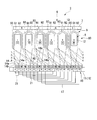
- FIG. 1 is an external side view of a motor with a reduction gear to which an electric motor including an armature core according to the present invention is applied.
- FIG. 2 is a longitudinal sectional view thereof.
- a motor 1 with a speed reducer is used for driving a wiper of an automobile, for example, and includes an electric motor 2 and a speed reduction mechanism 4 connected to a rotating shaft 3 of the electric motor 2. And.
- the electric motor 2 includes a yoke 5 that also serves as a bottomed cylindrical motor housing, and an armature 6 that is rotatably provided in the yoke 5.
- the cylindrical portion 53 of the yoke 5 is formed in a substantially cylindrical shape, and four segment type magnets 7 are disposed on the inner peripheral surface of the cylindrical portion 53.
- the magnet 7 is not limited to the segment type, and a ring type may be used.
- the bottom wall (end portion) 51 of the yoke 5 is formed with a bearing housing 19 projecting outward in the axial direction at the center in the radial direction, and a sliding bearing for rotatably supporting one end of the rotary shaft 3 therein. 18 is provided.
- the sliding bearing 18 has a centering function of the rotating shaft 3.
- An outer flange portion 52 is provided at the opening of the cylindrical portion 53, and the end of the gear housing 23 of the speed reduction mechanism 4 is fixed to the outer flange portion 52, so that the electric motor 2 and the speed reduction mechanism 4 are integrated. Are combined.
- FIG. 3 is an external side view of the armature.
- the armature 6 includes an armature body 80 that is externally fitted and fixed to the rotating shaft 3, and a commutator 10 that is disposed on the other end side (the speed reduction mechanism 4 side) of the rotating shaft 3. ing.
- the armature body 80 has an armature core 8 and an armature coil 9 wound around the armature core 8.
- the armature core 8 is formed of a laminated core formed by laminating a core plate of a magnetic material punched out by pressing or the like in the axial direction.
- FIG. 4A is a diagram of the armature core viewed from the axial direction, and is also a diagram illustrating a planar shape of one core plate.
- FIG. 4B is an enlarged view in which the windings in section B of FIG. 4A are drawn together.
- FIG. 5 is a partially enlarged cross-sectional view of an armature core wound with a winding.
- the “axial direction” is the axial direction of the armature 6, that is, the axial direction of the rotary shaft 3.
- the “radial direction” is the radial direction of the armature 6.
- the “radially inward” is a direction toward the rotary shaft 3 in the radial direction of the armature 6, and the “radially outward” is the opposite direction.
- the “circumferential direction” is the circumferential direction of the armature 6 and the circumferential direction of the rotating shaft 3.
- the armature core described below is indicated by a common symbol “8” when it is described regardless of a difference in a fine shape, and when it is described by being slightly different in shape for each embodiment, the common symbol “8” is used. ] With capital letters added.
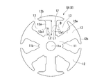
- the armature core 8 ⁇ / b> A (8) in the first embodiment has an annular core body 11.
- a through hole 11 a for press-fitting the rotating shaft 3 is formed at the center of the core body 11.
- six teeth 12 are radially provided on the outer peripheral portion of the core body 11 at equal intervals in the circumferential direction.
- Each tooth 12 is formed in a substantially T shape in an axial plan view.
- Each of the teeth 12 includes a winding drum portion 12a that protrudes radially from the core body 11 along the radial direction, a flange portion 12b that extends from the tip of the winding drum portion 12a in the circumferential direction, and that forms the outer periphery of the armature core 8A. It is comprised by.
- the three coils 91, 92, and 93 constituting the armature coil 9 are wound around the outer periphery of the winding body 12 a of each tooth 12 in order by the concentrated winding method.
- winding 14 which comprises the 1st coil 91 is wound around the teeth 12 as the 1st layer.
- the winding wire 14 constituting the second coil 92 is wound around the tooth 12 as the second layer.
- the winding wire 14 constituting the third coil 93 is wound around the tooth 12 as the third layer.
- each core plate of the armature core 8A is coated with powder such as epoxy resin and an insulating film is formed on the surface. Therefore, the insulator of the resin molded product which is another part is not used.
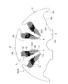
- the coil 91 of the first layer described above is formed by winding the winding 14 around the winding surface on the inner side in the radial direction (extending direction) of the winding body 12 a of each tooth 12. Further, the coil 92 of the second layer is wound by winding the winding wire 14 so as to partially overlap the coil 91 of the first layer wound earlier at a position more radially outward from above. Is formed. Further, the third layer coil 93 is further wound around the coil 14 at a position further outward in the radial direction so as to partially overlap the previously wound second layer coil 92. It is formed with. Here, the coil 91 of the first layer is wound in a state where the lowermost winding 14 is in close contact with the winding surface on the proximal end side of the winding body 12a.
- the windings 14 constituting the coils 91, 92, and 92 are sequentially wound, the windings 14 of the first layer coil 91 are wound on the windings as described above.
- the force at the time of winding of the coil 92 of the second layer may cause slipping on the winding body 12a, causing slack, and causing the coil to collapse.
- a restricting portion 12a1 is provided on at least a part of the winding surface of the first layer coil 91 on the outer periphery of the winding body portion 12a. ing.
- the regulating portion 12a1 regulates the positional deviation in the radial direction of the lowermost winding 14 of the first layer coil 91. Since the winding drum portion 12a of the tooth 12 has a rectangular cross section, the restriction portion 12a1 may be provided on the winding surface (one of the four winding surfaces) corresponding to at least one side of the rectangular cross section.
- the armature core 8A is a laminated core, here, on both side surfaces in the width direction of the winding body portion 12a when viewed from the axial direction of the four winding surfaces corresponding to the four sides of the rectangular cross section.
- a restricting portion 12a1 is provided.
- the restricting portion 12a1 is provided continuously in the axial direction.
- the restricting portion 12a1 in the armature core 8A of this embodiment is configured by a step 12a1 (indicated by the same reference numeral as the restricting portion) provided at the radially outer end of the winding surface of the coil 91 of the first layer. ing. Then, with the step 12a1 as a boundary, the winding surface of the first layer coil 91 on the radially inner side is lower than the winding surfaces of the other coils 92, 93 on the radially outer side. Is set. That is, the step 12a1 is formed by the change in the width dimension of the tooth 12.
- the length L2 in the extending direction of the teeth 12 (winding body portion 12a) of the winding surface of the first layer coil 91 provided with the step 12a1 is the total winding in the extending direction of the teeth 12. It is set to half or less of the length L1 of the attached surface.
- the step 12a1 is formed at the center in the extending direction of the teeth 12 (the winding drum portion 12a) or on the inner side in the extending direction from the center.
- the height (height difference) H of the step 12 a 1 is set to be equal to or larger than the radius h of the winding 14 constituting the coil 91.
- the armature core 8A Since the armature core 8A is configured in this way, the winding 14 of the first coil 91, the winding 14 of the second coil 92, the third winding 12a of each tooth 12 of the armature core 8A, and the third By winding the windings 14 of the coil 93 in order, the armature coil 9 composed of the three coils 91, 92, and 93 that are not collapsed can be configured.
- the winding 14 of the first coil 91 in the first layer is wound in close contact with the winding surface on the radially inner side of the winding body 12 a of the tooth 12. Then, the position of the winding 14 that directly hits the step 12a1 in the lowermost winding 14 of the first layer coil 91 is restricted by the step 12a1 so as not to move radially outward. Then, the position of the other lowermost winding 14 is similarly restricted in accordance therewith.
- the armature coil 9 is completed by winding the coils 92 and 93 of the second layer and the third layer in order while overlapping a part of the coils on the lower coil.
- the position of the lowermost winding 14 of the first layer coil 91 is restricted by the step 12a1.
- the winding 14 is not loosened by slipping, and the entire coil is not collapsed, and the winding state of the coils 91, 92, 93 is stabilized.
- the winding space in the slot 13 of the armature core 8A is increased, and the coil space factor is improved.
- the arrangement of the coils 91, 92, 93 in each tooth 12 is equalized, so that the balance of the armature 6 can be improved.
- the lowermost winding 14 of the first-layer coil 91 can be reliably held at an appropriate position by setting the position where the step 12a1 is provided (position regulated by the dimension L2) and the height difference H. That is, it is possible to prevent the lowermost winding 14 of the first layer coil 91 from climbing over the step 12a1. For this reason, the coil 91, 92, 93 can be reliably prevented from being collapsed.
- the commutator 10 that is externally fitted and fixed to the other end side (the speed reduction mechanism 4 side) of the armature core 8 of the rotating shaft 3 has a segment 15 formed of a conductive material on the outer peripheral surface. 18 are attached.
- the segment 15 is made of a plate-like metal piece that is long in the axial direction.
- the segments 15 are fixed in parallel at equal intervals along the circumferential direction while being insulated from each other.
- the electric motor 2 is configured as a so-called four-pole six-slot 18-segment electric motor in which the number of magnetic poles is four, the number of slots 13 is six, and the number of segments 15 is eighteen.
- a riser 16 that is folded in a shape that is folded back to the outer diameter side is integrally formed at the end of each segment 15 on the armature core 8 side.
- a terminal portion of the armature coil 9 is wound around the riser 16 and fixed by fusing or the like. Thereby, the segment 15 and the armature coil 9 corresponding to this are conducted.
- connection line 17 (described later) is wound around each riser 16 corresponding to the segment 15 having the same potential, and the connection line 17 is fixed to the riser 16 by fusing.
- the connection line 17 is for short-circuiting the segments 15 having the same potential.
- the connection line 17 is routed between the commutator 10 and the armature core 8.
- the commutator 10 configured in this manner faces the gear housing 23 of the speed reduction mechanism 4 as shown in FIG.
- a gear group 41 of the speed reduction mechanism 4 is housed in the gear housing 23.
- a brush housing portion 22 is integrally formed on the gear housing 23 on the electric motor 2 side.
- the commutator 10 of the electric motor 2 faces the brush housing portion 22.
- the brush 21 is housed inside the brush housing part 22 through a holder stay and a brush holder (not shown) so as to be able to appear and retract.
- the brush 21 is for supplying electric power from an external power source (for example, a battery mounted on an automobile) to the commutator 10.
- the brush 21 is biased toward the commutator 10 by a spring (not shown), and the tip thereof is in sliding contact with the segment 15.
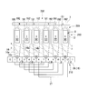
- FIG. 6 is a development view of the armature. A gap between adjacent teeth corresponds to a slot. In the following FIG. 6, each segment 15, each tooth 12, and the formed armature coil 9 will be described with reference numerals.
- the U phase, the V phase, and the W phase are assigned to the teeth 12 in this order in the circumferential direction. That is, the first and fourth teeth 12 are the U phase, the second and fifth teeth 12 are the V phase, and the third and sixth teeth 12 are the W phase.
- the position corresponding to No. 1 is the position corresponding to the No. 1 tooth 12.
- the winding 14 is then drawn into the slot 13 between the 1-6th teeth 12 existing in the vicinity of the first segment 15. .
- n is a natural number and a multiple of 3
- the concentrated winding method is applied to the first tooth 12 n / 3 times in the forward direction. Wrap it.
- the winding 14 is pulled out from the slot 13 between the first and second teeth 12 and is wound around the riser 16 of the second segment 15 adjacent to the first segment 15. Then, the winding end 14 b is connected to the second segment 15. As a result, a U-phase first coil 91 wound around the first tooth 12 in the forward direction is formed between the first and second segments 15.
- the winding 14 is wound around the riser 16 of the fifth segment 15 and the winding start end 14 a is drawn into the slot 13 between the first and second teeth 12. And it winds to the 1st teeth 12 by the concentrated winding system in the reverse direction n / 3 times. Subsequently, the winding 14 is pulled out from the slot 13 between the 1-6th teeth 12 and is wound around the riser 16 of the 6th segment 15 adjacent to the 5th segment 15. Then, the winding end 14 b is connected to the sixth segment 15. As a result, a “ ⁇ U” phase second coil 92 wound around the first tooth 12 in the reverse direction is formed between the 5th and 6th segments 15.
- the winding 14 is wound around the riser 16 of the 6th segment 15 and the winding start end 14a is drawn into the slot 13 between the 1-2th teeth 12. And it winds to the 1st teeth 12 by the concentrated winding system in the reverse direction n / 3 times.
- the first tooth 12 corresponding to the U-phase has a U-phase first coil 91 formed by winding the winding 14 n / 3 times in the forward direction and the winding 14 n / 3 in the reverse direction.
- An n-turn armature coil 9 is formed, which is composed of a “ ⁇ U” -phase second coil 92 and a “ ⁇ U” -phase third coil 93 formed by winding.
- the armature core 8 is formed with the three-phase armature coil 9 including the first coil 91, the second coil 92, and the third coil 93 by sequentially performing this operation between the segments 15 corresponding to the respective phases. Between the adjacent segments 15, coils 91 to 93 of U, “ ⁇ W”, “ ⁇ W”, V, “ ⁇ U”, “ ⁇ U”, W, “ ⁇ V” and “ ⁇ V” phases are Electrically connected in order.
- connection positions of the winding start end 14a and the winding end end 14b of the windings 14 forming the coils 91 to 93 of each phase to the segments 15 are U, “ ⁇ W”, “ ⁇ W” between the adjacent segments 15.
- V, “ ⁇ U”, “ ⁇ U”, W, “ ⁇ V”, and “ ⁇ V” phase coils 91 to 93 may be electrically connected in this order.
- the U-phase first coil 91 is short-circuited. Then, a current in the reverse direction (counterclockwise direction in FIG. 6) flows through the second coil 92 of the “ ⁇ U” phase, and a forward direction (clockwise direction in FIG. 6) flows through the third coil 93 of the “ ⁇ U” phase. Current flows. That is, since currents in opposite directions flow through the second coil 92 and the third coil 93, the magnetic field is canceled and no torque is generated between the second coil 92 and the third coil 93.
- a magnetic field is formed in each of the second, third, fifth and sixth teeth 12.
- the directions of these magnetic fields are in order in the circumferential direction. For this reason, between the magnetic field formed in each tooth 12 and the magnet 7, a magnetic attractive force or repulsive force acts in the same direction at a point-symmetrical position about the rotation shaft 3. As a result, the rotating shaft 3 rotates.
- the brush 21 arranged between the first and second segments 15 can be advanced to rotate the rotating shaft 3 at a high speed.
- FIG. 7 is a development view of the armature in the first modification of the first embodiment.
- 18 segments 15 are attached to the commutator 10 of the first embodiment.
- 12 segments 15 are attached to the commutator 210 of the first modification.
- the electric motor 202 of this modification is configured as a so-called 4-pole 6-slot 12-segment electric motor in which the number of magnetic poles is 4 poles, the number of slots 13 is 6 and the number of segments 15 is 12. Yes.
- the armature core 8 constituting the armature of the first embodiment is formed with an armature coil 9 having a three-phase structure including three coils 91 to 93 including a first coil 91, a second coil 92, and a third coil 93.
- an armature core 209 having two coils of a first coil 91 and a second coil 92 is formed in the armature core 8 constituting the armature of the first modification. This is different from the first embodiment described above.
- each tooth 12 is assigned with a U phase, a V phase, and a W phase in this order in the circumferential direction. That is, the first and fourth teeth 12 are the U phase, the second and fifth teeth 12 are the V phase, and the third and sixth teeth 12 are the W phase.
- the position corresponding to No. 1 is the position corresponding to the No. 1 tooth 12.
- the segments 15 having the same potential are short-circuited by the connection line 17.
- the case where the winding direction of the winding 14 around each tooth 12 is clockwise is referred to as a forward direction
- the case where it is counterclockwise is referred to as a reverse direction.
- the winding 14 is then drawn into the slot 13 between the 1-6th teeth 12 existing in the vicinity of the first segment 15. .
- n is a natural number and a multiple of 2
- the concentrated winding method is applied to the first tooth 12 n / 2 times in the forward direction. Wrap it.
- the winding 14 is wound around the riser 16 of the No. 4 segment 15 and the winding start end 14 a is drawn into the slot 13 between the No. 1-2 teeth 12. Then, the first tooth 12 is wound n / 2 times in the reverse direction by the concentrated winding method.
- the first tooth 12 corresponding to the U phase has a first coil 91 of U phase formed by winding the winding 14 n / 2 times in the forward direction, and the winding 14 is n / in the reverse direction.
- An n-turn armature coil 209 composed of a second coil 92 of “ ⁇ U” phase formed by two turns is formed.
- the armature core 8 is formed with a three-phase armature coil 209 having a first coil 91 and a second coil 292 by sequentially performing this operation between the segments 15 corresponding to the respective phases.
- the coils 91 and 92 of U, “ ⁇ W”, V, “ ⁇ U”, W and “ ⁇ V” phases are electrically connected in this order.
- connection place to the segment 15 of the winding start end 14a and the winding end end 14b of the winding 14 forming the coils 91 and 92 of each phase is between the adjacent segments 15, U, “ ⁇ W”, V, “ The coils 91 and 92 of the “ ⁇ U”, W, and “ ⁇ V” phases may be electrically connected in this order.
- FIG. 8 is a development view of the armature in the second modification of the first embodiment.
- the number of magnetic poles is 4 (the number of magnetic pole pairs is 2).
- the number of magnetic poles is 6 (the number of magnetic pole pairs is 3).
- the number of the teeth 12 of the armature core 8 is six, which is nine.
- the number of the segments 15 of the commutator 310 is 18 instead of 12.
- the winding 14 is continuously wound around the teeth 12 having the same phase.
- the winding 14 wound around one tooth 12 is not once connected to the segment 15, but the in-phase teeth 12 (for example, the first tooth 12, the fourth tooth 12, No. 7 teeth 12) and windings 14 are wound around all teeth 12 of the same phase to form coils 91 and 92, and then the winding end ends of the windings 14 are connected to a predetermined segment 15.
- FIG. 9 is a diagram viewed from the axial direction of the armature core in the second embodiment.
- convex portions 12a2 are provided as restricting portions on both side surfaces in the width direction of the winding drum portion 12a of each tooth 12.
- the convex portion 12a2 also functions in the same manner as the step 12a1 of the first embodiment.
- FIG. 10A is an explanatory view of the armature core in the third embodiment, and is a view seen from the axial direction of the armature core.
- FIG. 10B is an enlarged view of a portion C in FIG. 10A.
- armature core 8C on both side surfaces in the width direction of the winding drum portion 12a of each tooth 12, a recess 12a3 into which the winding 14 constituting the first layer coil 91 is fitted as a regulating portion. Is provided.
- the depth d of the recess 12a3 is set to be equal to or less than the radius h of the winding.
- the winding 14 (14C) is fitted into the recess 12a3 formed on the winding surface, so that the winding 14C itself functions as a step similar to that of the first embodiment. For this reason, it is possible to prevent displacement of the lowermost winding of the first layer coil.
- FIG. 11 is a diagram viewed from the axial direction of the armature core in the fourth embodiment.
- the first step 12a4 and the second step 12a5 are radially inward as restricting portions on both sides in the width direction of the winding drum portion 12a of each tooth 12. It is provided in two stages with the position shifted from the outside.
- the first step 12a4 functions to prevent displacement of the coil 91 on the first layer surface
- the second step 12a5 functions to prevent displacement of the coil 92 on the second layer.
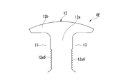
- FIG. 12 is a diagram viewed from the axial direction of the armature core in the fifth embodiment.
- this armature core 8E recesses 12a6 of a size to fit the windings 14 (see FIG. 5) are provided as restricting portions on both side surfaces in the width direction of the winding drum portion 12a of each tooth 12. A large number are continuously provided. Thus, by providing many recessed parts 12a6, there can exist an effect similar to 1st Embodiment.
- FIG. 13 is a diagram seen from the axial direction of the armature core in the sixth embodiment.
- a wire 12a7 having the same diameter as the winding 14 (see FIG. 5) is welded to both side surfaces in the width direction of the winding body 12a of each tooth 12 as a restricting portion. It is fixed by means such as adhesion.
- This wire 12a7 also has the same function as the step 12a1 of the first embodiment.
- the present invention is not limited to the above-described embodiment, and includes various modifications made to the above-described embodiment without departing from the spirit of the present invention.
- various restricting portions for preventing the winding 14 from collapsing are provided on the armature cores 8, 8A to 8F of the motor 1 with a reduction gear used for driving a wiper of an automobile.
- the present invention is not limited to this, and the restricting portion of the above-described embodiment can be applied to various armature cores of electric motors.
- the armature core, armature, and electric motor it is possible to prevent the coil from collapsing when a plurality of coils are wound around each tooth. Therefore, the coil space factor in the armature can be improved and the balance can be improved.
Abstract
Description
本願は、2014年3月5日に、日本に出願された特願2014-042659号に基づき優先権を主張し、その内容をここに援用する。 The present invention relates to an armature core in which a plurality of coils are wound around each tooth, an armature configured by winding a plurality of coils around the armature core, and an electric motor using the armature.
This application claims priority based on Japanese Patent Application No. 2014-042659 filed in Japan on March 5, 2014, the contents of which are incorporated herein by reference.
アーマチュアは、回転軸に外嵌固定される円環状のコア本体の外周に、径方向外方に向かって放射状に延びる複数のティースを設けたアーマチュアコアと、該アーマチュアコアの各ティースにティース間のスロットを介して巻回されたアーマチュアコイルと、アーマチュアコアと一体回転するように前記回転軸上に設けられるコンミテータと、を備えている。 As an electric motor, for example, a DC motor with a brush in which a motor magnet is disposed on the inner peripheral surface of a bottomed cylindrical yoke and an armature is rotatably provided radially inward of the motor magnet is known ( For example, see Patent Document 1).
The armature includes an armature core having a plurality of teeth radially extending outward in the radial direction on the outer periphery of an annular core body that is externally fitted and fixed to a rotating shaft, and each tooth of the armature core is provided between teeth. An armature coil wound through a slot; and a commutator provided on the rotating shaft so as to rotate integrally with the armature core.
この図14においては、ティース1012の巻胴部1012bの巻付面に第1のコイル1091を巻回し、その上に第2のコイル1092を巻回し、その上に第3のコイル1093を巻回しているが、第1のコイル1091の最下側に弛み(図14中Aで示す箇所)が生じることにより、コイル全体に巻崩れが起こっている。このような巻崩れが起きると、スロット1013内の巻線スペースが減少し、巻線可能なコイル占積率が低下する。また、各ティース1012上における各コイルの配置が不均一になることにより、アーマチュア1080のバランスが悪化する等の可能性がある。 When the coil wound on the lower side is caused to slip by the coil wound on the upper side, the lower coil may be loosened and collapsed. FIG. 14 shows an example.
In FIG. 14, the
(減速機付モータ)
次に、本発明の第1実施形態を図1~図6に基づいて説明する。
図1は、本発明に係るアーマチュアコアを備える電動モータが適用された減速機付モータの外観側面図である。図2は、その縦断面図である。 (First embodiment)
(Motor with reduction gear)
Next, a first embodiment of the present invention will be described with reference to FIGS.
FIG. 1 is an external side view of a motor with a reduction gear to which an electric motor including an armature core according to the present invention is applied. FIG. 2 is a longitudinal sectional view thereof.
図3は、アーマチュアの外観側面図である。
図2および図3に示すように、アーマチュア6は、回転軸3に外嵌固定されたアーマチュア本体80と、回転軸3の他端側(減速機構4側)に配置されたコンミテータ10とを備えている。 (Armature)
FIG. 3 is an external side view of the armature.
As shown in FIGS. 2 and 3, the
図4Aは、アーマチュアコアを軸方向から見た図であって、1枚のコアプレートの平面形状を示す図でもある。図4Bは、図4AのB部の巻線を一緒に描いた拡大図である。また、図5は、巻線を巻いたアーマチュアコアの部分拡大断面図である。 (Armature core)
FIG. 4A is a diagram of the armature core viewed from the axial direction, and is also a diagram illustrating a planar shape of one core plate. FIG. 4B is an enlarged view in which the windings in section B of FIG. 4A are drawn together. FIG. 5 is a partially enlarged cross-sectional view of an armature core wound with a winding.
また、以下に説明するアーマチュアコアは、細かい形状の違いに拘りなく述べる場合は、共通符号「8」で示し、実施形態ごとに僅かに形状が違うことで区別して述べる場合は、共通符号「8」に大文字アルファベットを追加して示す。 Here, we define terms for the directions used below. First, the “axial direction” is the axial direction of the
In addition, the armature core described below is indicated by a common symbol “8” when it is described regardless of a difference in a fine shape, and when it is described by being slightly different in shape for each embodiment, the common symbol “8” is used. ] With capital letters added.
図4Aに示すように、この第1実施形態におけるアーマチュアコア8A(8)は、円環状のコア本体11を有している。コア本体11の中心には、回転軸3を圧入するための貫通孔11aが形成されている。また、コア本体11の外周部には、周方向に等間隔にティース12が放射状に6つ設けられている。各ティース12は、軸方向平面視略T字型に形成されたものである。各ティース12は、コア本体11から径方向に沿って放射状に突出する巻胴部12aと、巻胴部12aの先端から周方向に沿って延び、アーマチュアコア8Aの外周を構成する鍔部12bとにより構成されている。 (Armature core)
As shown in FIG. 4A, the
この場合、図5に示すように、各ティース12の巻胴部12aの外周には、アーマチュアコイル9を構成する3つのコイル91、92、93が順番に集中巻方式で巻回されている。まず、第1コイル91を構成する巻線14が1層目としてティース12に巻回されている。次にその上から第2コイル92を構成する巻線14が2層目としてティース12に巻回されている。そして、最後に第3コイル93を構成する巻線14が3層目としてティース12に巻回されている。なお、コイル91、92、93の巻回に先立って、アーマチュアコア8Aの各コアプレートには、エポキシ樹脂等の粉末塗装が施されて表面に絶縁膜が形成されているものとする。よって、別部品である樹脂成形品のインシュレータは使用していない。 (Armature coil)
In this case, as shown in FIG. 5, the three
前述した1層目のコイル91は、各ティース12の巻胴部12aの径方向(延在方向)内方側の巻付面に巻線14を巻回することで形成されている。また、2層目のコイル92は、その上から、より径方向外方寄りの位置に、先に巻いた1層目のコイル91に一部が重なるように巻線14を巻回することで形成されている。また、3層目のコイル93は、更にその上から、より径方向外方寄りの位置に、先に巻いた2層目のコイル92に一部が重なるように巻線14を巻回することで形成されている。ここで、1層目のコイル91は、最下側の巻線14が、巻胴部12aの基端側の巻付面上に密着する状態で巻回されている。 (3 coils)
The
そこで、この実施形態のアーマチュアコア8Aでは、図4Aおよび図5に示すように、巻胴部12aの外周の1層目のコイル91の巻付面の少なくとも一部に、規制部12a1が設けられている。規制部12a1は、1層目のコイル91の最下側の巻線14の径方向における位置ずれを規制するものである。ティース12の巻胴部12aは、断面矩形であるから、断面矩形の少なくとも1辺に相当する巻付面(4つの巻付面のうちの1つ)に規制部12a1があればよい。しかし、ここでは、アーマチュアコア8Aが積層コアであることを考慮して、矩形断面の4辺に相当する4つの巻付面のうちの軸方向から見て巻胴部12aの幅方向両側面に規制部12a1が設けられている。なお、規制部12a1は、軸方向に連続して設けられている。 (Regulation Department)
Therefore, in the
この実施形態のアーマチュアコア8Aにおける規制部12a1は、1層目のコイル91の巻付面の径方向外方側の端部に設けられた段差12a1(規制部と同符号で示す)によって構成されている。そして、その段差12a1を境に、径方向内方側の1層目のコイル91の巻付面が、径方向外方側のそれ以外のコイル92、93の巻付面よりも高さが低く設定されている。つまり、ティース12の幅寸法の変化によって、段差12a1が形成されている。 (Step as a regulation part)
The restricting portion 12a1 in the
また、図4Bに示すように、段差12a1の高さ(高低差)Hは、コイル91を構成する巻線14の半径h以上に設定されている。 As shown in FIG. 4A, the length L2 in the extending direction of the teeth 12 (winding
Further, as shown in FIG. 4B, the height (height difference) H of the
このようにアーマチュアコア8Aが構成されているので、このアーマチュアコア8Aの各ティース12の巻胴部12aに、第1コイル91の巻線14と、第2コイル92の巻線14と、第3コイル93の巻線14とを順番に巻回することにより、巻崩れのない3つのコイル91、92、93からなるアーマチュアコイル9を構成することができる。 (Effects of steps)
Since the
次に、アーマチュアの他の構成について述べる。
図2および図3に示すように、回転軸3のアーマチュアコア8よりも他端側(減速機構4側)に外嵌固定されたコンミテータ10には、外周面に導電材で形成されたセグメント15が18枚取り付けられている。セグメント15は、軸方向に長い板状の金属片からなる。セグメント15は、互いに絶縁された状態で周方向に沿って等間隔に並列に固定されている。このように、電動モータ2は、磁極数が4極、スロット13の個数が6つ、セグメント15の枚数が18枚に設定されたいわゆる4極6スロット18セグメントの電動モータとして構成されている。 (Commutator)
Next, another configuration of the armature will be described.
As shown in FIGS. 2 and 3, the
次に、図6に基づいて、アーマチュアコイル9の形成方法の一例について説明する。
図6は、アーマチュアの展開図である。隣接するティース間の空隙は、スロットに相当している。なお、以下の図6においては、各セグメント15、各ティース12、および、形成されたアーマチュアコイル9にそれぞれ符号を付して説明する。 (Method for forming armature coil)
Next, an example of a method for forming the
FIG. 6 is a development view of the armature. A gap between adjacent teeth corresponds to a slot. In the following FIG. 6, each
続いて、1-6番ティース12の間のスロット13から巻線14を引き出し、5番セグメント15に隣接する6番セグメント15のライザ16に掛け回す。そして、6番セグメント15に巻き終わり端14bを接続する。これにより、5-6番セグメント15間には、1番ティース12に逆方向に巻回された「-U」相の第2コイル92が形成される。 In addition, the winding 14 is wound around the
Subsequently, the winding 14 is pulled out from the
次に、図6に基づいて、電動モータ2の動作について説明する。
電動モータ2の動作説明にあたり、例えば、図6に示すように、1-2番セグメント15間にブラシ21が配置されると共に、6番セグメント15にブラシ21が配置され、これら2つのブラシ21の間に電圧が印加された場合について説明する。 (Operation of electric motor)
Next, the operation of the
In describing the operation of the
なお、例えば、上述の電動モータ2の動作の説明において、1-2番セグメント15間に配置されたブラシ21を進角させ、回転軸3を高速回転させることも可能である。 Then, a magnetic field is formed in each of the second, third, fifth and
For example, in the description of the operation of the
図7は、第1実施形態の第1変形例におけるアーマチュアの展開図である。
同図に示すように、第1実施形態のコンミテータ10には、セグメント15が18枚取り付けられている。これに対し、第1変形例のコンミテータ210には、セグメント15が12枚(ティース12の数の2倍の枚数)取り付けられている。この点、前述の第1実施形態と相違する。すなわち、この変形例の電動モータ202は、磁極数が4極、スロット13の個数が6つ、セグメント15の枚数が12枚に設定されたいわゆる4極6スロット12セグメントの電動モータとして構成されている。 (First modification)
FIG. 7 is a development view of the armature in the first modification of the first embodiment.
As shown in the figure, 18
図7に基づいて、アーマチュアコイル209の形成方法の一例について説明する。 (Method for forming armature coil)
An example of a method for forming the
図8は、第1実施形態の第2変形例におけるアーマチュアの展開図である。
同図に示すように、第1変形例では磁極数が4極(磁極対数2)になっていた。これに対し、第2変形例では磁極数が6極(磁極対数3)になる。また、アーマチュアコア8のティース12の数が6個であったのが9個になる。さらに、コンミテータ310のセグメント15の個数が、12枚であったのが18枚になる。これらの点が前述の第1変形例と相違する。各ティース12には、第1コイル91と第2コイル92がこの順番で巻回されている。 (Second modification)
FIG. 8 is a development view of the armature in the second modification of the first embodiment.
As shown in the figure, in the first modification, the number of magnetic poles is 4 (the number of magnetic pole pairs is 2). On the other hand, in the second modified example, the number of magnetic poles is 6 (the number of magnetic pole pairs is 3). Further, the number of the
図9は、第2実施形態におけるアーマチュアコアの軸方向から見た図である。
同図に示すように、このアーマチュアコア8Bでは、各ティース12の巻胴部12aの幅方向の両側面に、規制部として凸部12a2が設けられている。この凸部12a2も、第1実施形態の段差12a1と同じ働きをする。 (Second Embodiment)
FIG. 9 is a diagram viewed from the axial direction of the armature core in the second embodiment.
As shown in the figure, in this
図10Aは、第3実施形態におけるアーマチュアコアの説明図で、アーマチュアコアの軸方向から見た図である。図10Bは、図10AのC部の拡大図である。
図10Aに示すように、このアーマチュアコア8Cでは、各ティース12の巻胴部12aの幅方向の両側面に、規制部として、1層目のコイル91を構成する巻線14の嵌まる凹部12a3が設けられている。 (Third embodiment)
FIG. 10A is an explanatory view of the armature core in the third embodiment, and is a view seen from the axial direction of the armature core. FIG. 10B is an enlarged view of a portion C in FIG. 10A.
As shown in FIG. 10A, in this
図11は、第4実施形態におけるアーマチュアコアの軸方向から見た図である。
同図に示すように、このアーマチュアコア8Dでは、各ティース12の巻胴部12aの幅方向の両側に、規制部として、1段目の段差12a4と2段目の段差12a5が径方向内方から外方に位置をずらして2段に設けられている。この場合、1段目の段差12a4は、1層面のコイル91のずれ防止用、2段目の段差12a5は2層目のコイル92のずれ防止用として機能する。 (Fourth embodiment)
FIG. 11 is a diagram viewed from the axial direction of the armature core in the fourth embodiment.
As shown in the figure, in this armature core 8D, the first step 12a4 and the second step 12a5 are radially inward as restricting portions on both sides in the width direction of the winding
図12は、第5実施形態におけるアーマチュアコアの軸方向から見た図である。
同図に示すように、このアーマチュアコア8Eでは、各ティース12の巻胴部12aの幅方向の両側面に、規制部として、巻線14(図5参照)の嵌まる大きさの凹部12a6が連続して多数設けられている。このように、多数の凹部12a6を設けることにより、第1実施形態と同様の効果を奏することができる。 (Fifth embodiment)
FIG. 12 is a diagram viewed from the axial direction of the armature core in the fifth embodiment.
As shown in the figure, in this
図13は、第6実施形態におけるアーマチュアコアの軸方向から見た図である。
図13に示すように、このアーマチュアコア8Fでは、各ティース12の巻胴部12aの幅方向の両側面に、規制部として、巻線14(図5参照)と同じ径の線材12a7が溶接、接着等の手段で固着されている。この線材12a7も、第1実施形態の段差12a1と同じ働きをする。 (Sixth embodiment)
FIG. 13 is a diagram seen from the axial direction of the armature core in the sixth embodiment.
As shown in FIG. 13, in this
例えば、上述の実施形態では、自動車のワイパ駆動用に用いる減速機付モータ1のアーマチュアコア8,8A~8Fに、巻線14の巻崩れを防止するためのさまざまな規制部を設けた場合について説明した。しかしながら、これに限られるものではなく、さまざまな電動モータのアーマチュアコアに、上述の実施形態の規制部を適用することができる。 The present invention is not limited to the above-described embodiment, and includes various modifications made to the above-described embodiment without departing from the spirit of the present invention.
For example, in the above-described embodiment, a case where various restricting portions for preventing the winding 14 from collapsing are provided on the
2 電動モータ
6 アーマチュア
8,8A~8F アーマチュアコア
11 コア本体
12 ティース
12a 巻胴部
12a1 段差(規制部)
12a2 凸部(規制部)
12a3 凹部(規制部)
12a4 第1の段差(規制部)
12a5 第2の段差(規制部)
12a6 凹部(規制部)
12a7 線材(規制部)
14 巻線
91,92,93 コイル DESCRIPTION OF
12a2 Convex part (regulation part)
12a3 recess (regulator)
12a4 First step (regulator)
12a5 Second step (regulator)
12a6 recess (regulator)
12a7 wire rod (regulation section)
14
Claims (8)
- 円環状のコア本体の外周に径方向外方に向けて放射状に延在する複数のティースを有し、前記各ティースの巻胴部に複数のコイルが巻回され、少なくとも1層目のコイルの最下側の巻線が、前記巻胴部の基端側の巻付面に密着して巻回されると共に、後から巻回される2層目のコイルが、その少なくとも一部を前記1層目のコイルの上に重ねて巻回されるアーマチュアコアにおいて、
前記巻胴部の外周の前記1層目のコイルの巻付面の少なくとも一部に、前記1層目のコイルの最下側の巻線の、前記ティースの延在方向における位置ずれを規制する規制部が設けられているアーマチュアコア。 A plurality of teeth radially extending outward in the radial direction are provided on the outer periphery of the annular core body, and a plurality of coils are wound around the winding body of each of the teeth. The lowermost winding is wound in close contact with the winding surface on the proximal end side of the winding body portion, and the second-layer coil wound later is at least a part of the first winding. In the armature core wound on top of the coil of the layer,
The positional deviation in the extending direction of the teeth of the lowermost winding of the first layer coil is restricted to at least a part of the winding surface of the first layer coil on the outer periphery of the winding drum portion. An armature core with a restriction section. - 前記コア本体の軸方向から見たときの前記巻胴部の幅方向両側面のうちの少なくとも一方の側面に、前記規制部が設けられている請求項1に記載のアーマチュアコア。 The armature core according to claim 1, wherein the restriction portion is provided on at least one side surface of both side surfaces in the width direction of the winding body portion when viewed from the axial direction of the core body.
- 前記規制部は、前記巻胴部の前記延在方向の中央、または前記延在方向の中央よりも前記延在方向内方側に設けられている請求項1または請求項2に記載のアーマチュアコア。 3. The armature core according to claim 1, wherein the restricting portion is provided at a center of the winding body portion in the extending direction or on an inner side in the extending direction than a center of the extending direction. .
- 前記規制部は、前記1層目のコイルの巻付面の前記延在方向外方側の端部に設けられた段差によって構成されており、該段差を境に、前記延在方向内方側の前記1層目のコイルの巻付面が、前記延在方向外方側の巻付面よりも高さが低く設定されている請求項1~請求項3の何れか1項に記載のアーマチュアコア。 The restricting portion is configured by a step provided at an end portion on the outer side in the extending direction of the winding surface of the coil of the first layer, and the inner side in the extending direction with the step as a boundary. The armature according to any one of claims 1 to 3, wherein a winding surface of the coil of the first layer is set lower than a winding surface on the outer side in the extending direction. core.
- 前記段差の高低差が、前記コイルを構成する巻線の半径以上に設定されている請求項4に記載のアーマチュアコア。 The armature core according to claim 4, wherein a difference in height of the step is set to be equal to or larger than a radius of a winding constituting the coil.
- 前記規制部は、前記1層目のコイルの巻付面の前記延在方向外方側の端部に形成され、前記コイルを構成する巻線の嵌まる凹部であり、
前記凹部の深さは、前記巻線の半径以下に設定されている請求項1~請求項3の何れか1項に記載のアーマチュアコア。 The restricting portion is formed at an end portion on the outer side in the extending direction of the winding surface of the coil of the first layer, and is a concave portion into which a winding constituting the coil is fitted,
The armature core according to any one of claims 1 to 3, wherein a depth of the recess is set to be equal to or less than a radius of the winding. - 請求項1~請求項6の何れか1項に記載のアーマチュアコアの各ティースの巻胴部に、複数のコイルが集中巻方式で順番に巻回されており、前記巻胴部の巻付面に最下側の巻線が密着するように1層目のコイルが巻回された上に、2層目以降のコイルが、その少なくとも一部が前記1層目のコイルの上に重なるように巻回されているアーマチュア。 A plurality of coils are wound in order on the winding body of each tooth of the armature core according to any one of claims 1 to 6 in a concentrated winding manner, and the winding surface of the winding body is The first layer coil is wound so that the lowermost winding is in close contact with the second layer coil, and the second layer and subsequent coils overlap at least partly with the first layer coil. A wound armature.
- 請求項7に記載のアーマチュアと、該アーマチュアにより形成される磁界に対し、磁気的な吸引力や反発力を生じさせるマグネットと、を備えた電動モータ。 An electric motor comprising: the armature according to claim 7; and a magnet that generates a magnetic attractive force or a repulsive force against a magnetic field formed by the armature.
Priority Applications (3)
| Application Number | Priority Date | Filing Date | Title |
|---|---|---|---|
| US15/117,171 US20160352176A1 (en) | 2014-03-05 | 2015-03-04 | Armature core, armature, and electric motor |
| CN201580011870.1A CN106063083B (en) | 2014-03-05 | 2015-03-04 | Armature core, armature and motor |
| EP15758671.0A EP3116101B1 (en) | 2014-03-05 | 2015-03-04 | Armature core, armature, and electric motor |
Applications Claiming Priority (2)
| Application Number | Priority Date | Filing Date | Title |
|---|---|---|---|
| JP2014042659A JP6334961B2 (en) | 2014-03-05 | 2014-03-05 | Armature core, armature, and electric motor |
| JP2014-042659 | 2014-03-05 |
Publications (1)
| Publication Number | Publication Date |
|---|---|
| WO2015133518A1 true WO2015133518A1 (en) | 2015-09-11 |
Family
ID=54055320
Family Applications (1)
| Application Number | Title | Priority Date | Filing Date |
|---|---|---|---|
| PCT/JP2015/056345 WO2015133518A1 (en) | 2014-03-05 | 2015-03-04 | Armature core, armature, and electric motor |
Country Status (5)
| Country | Link |
|---|---|
| US (1) | US20160352176A1 (en) |
| EP (1) | EP3116101B1 (en) |
| JP (1) | JP6334961B2 (en) |
| CN (1) | CN106063083B (en) |
| WO (1) | WO2015133518A1 (en) |
Families Citing this family (4)
| Publication number | Priority date | Publication date | Assignee | Title |
|---|---|---|---|---|
| KR101923359B1 (en) | 2015-11-25 | 2018-11-28 | 미쓰비시덴키 가부시키가이샤 | Manufacturing method of rotary electric and rotary electric |
| JP6526103B2 (en) * | 2017-05-22 | 2019-06-05 | ファナック株式会社 | Reactor having an outer peripheral core divided into a plurality of parts and method of manufacturing the same |
| CN109428423B (en) * | 2017-08-22 | 2020-09-25 | 马渊马达株式会社 | Stator and manufacturing method thereof, motor and manufacturing method thereof, and winding method |
| IT201900024652A1 (en) * | 2019-12-19 | 2021-06-19 | Cebi Motors S P A | DIRECT CURRENT ELECTRIC MOTOR, ESPECIALLY FOR APPLICATIONS IN THE AUTOMOTIVE SECTOR |
Citations (10)
| Publication number | Priority date | Publication date | Assignee | Title |
|---|---|---|---|---|
| JPH11252843A (en) * | 1998-03-02 | 1999-09-17 | Asmo Co Ltd | Winding method of armature, armature and dc machine |
| JPH11299132A (en) * | 1998-04-07 | 1999-10-29 | Shibaura Mechatronics Corp | Stator core for motor |
| JP2004350450A (en) * | 2003-05-23 | 2004-12-09 | Honda Motor Co Ltd | Stator |
| JP2005269766A (en) * | 2004-03-18 | 2005-09-29 | Denso Corp | Dc motor |
| WO2007055210A1 (en) * | 2005-11-11 | 2007-05-18 | Sumitomo Electric Industries, Ltd. | Motor core part and motor part |
| JP2008125277A (en) * | 2006-11-14 | 2008-05-29 | Sumitomo Electric Ind Ltd | Stator and winding for rotary electric machine |
| JP2008236854A (en) * | 2007-03-19 | 2008-10-02 | Nissan Motor Co Ltd | Insulating insulator, structure of stator and manufacturing method |
| JP2008278604A (en) * | 2007-04-26 | 2008-11-13 | Sumitomo Electric Ind Ltd | Split core part |
| JP2008306816A (en) * | 2007-06-06 | 2008-12-18 | Sumitomo Electric Ind Ltd | Manufacturing method of divided stator, manufacturing method of stator, and manufacturing method of motor |
| JP2010239726A (en) * | 2009-03-31 | 2010-10-21 | Hitachi Automotive Systems Ltd | Rotary electric machine |
Family Cites Families (7)
| Publication number | Priority date | Publication date | Assignee | Title |
|---|---|---|---|---|
| JP3296681B2 (en) * | 1995-04-10 | 2002-07-02 | 株式会社日立製作所 | Commutator motor |
| JP5233497B2 (en) * | 2008-08-18 | 2013-07-10 | 株式会社デンソー | Electric motor |
| JP5379550B2 (en) * | 2009-04-21 | 2013-12-25 | 三菱電機株式会社 | Armature |
| JP5004110B2 (en) * | 2010-07-30 | 2012-08-22 | 本田技研工業株式会社 | Outer rotor type salient pole concentrated winding motor |
| JP5843156B2 (en) * | 2011-06-13 | 2016-01-13 | 日本電産株式会社 | Stator unit and motor |
| JP5261539B2 (en) * | 2011-06-13 | 2013-08-14 | トヨタ自動車株式会社 | Electromagnetic rotating electric machine |
| JP5963593B2 (en) * | 2012-07-26 | 2016-08-03 | 日立オートモティブシステムズ株式会社 | Rotating electric machine |
-
2014
- 2014-03-05 JP JP2014042659A patent/JP6334961B2/en active Active
-
2015
- 2015-03-04 US US15/117,171 patent/US20160352176A1/en not_active Abandoned
- 2015-03-04 EP EP15758671.0A patent/EP3116101B1/en active Active
- 2015-03-04 WO PCT/JP2015/056345 patent/WO2015133518A1/en active Application Filing
- 2015-03-04 CN CN201580011870.1A patent/CN106063083B/en active Active
Patent Citations (10)
| Publication number | Priority date | Publication date | Assignee | Title |
|---|---|---|---|---|
| JPH11252843A (en) * | 1998-03-02 | 1999-09-17 | Asmo Co Ltd | Winding method of armature, armature and dc machine |
| JPH11299132A (en) * | 1998-04-07 | 1999-10-29 | Shibaura Mechatronics Corp | Stator core for motor |
| JP2004350450A (en) * | 2003-05-23 | 2004-12-09 | Honda Motor Co Ltd | Stator |
| JP2005269766A (en) * | 2004-03-18 | 2005-09-29 | Denso Corp | Dc motor |
| WO2007055210A1 (en) * | 2005-11-11 | 2007-05-18 | Sumitomo Electric Industries, Ltd. | Motor core part and motor part |
| JP2008125277A (en) * | 2006-11-14 | 2008-05-29 | Sumitomo Electric Ind Ltd | Stator and winding for rotary electric machine |
| JP2008236854A (en) * | 2007-03-19 | 2008-10-02 | Nissan Motor Co Ltd | Insulating insulator, structure of stator and manufacturing method |
| JP2008278604A (en) * | 2007-04-26 | 2008-11-13 | Sumitomo Electric Ind Ltd | Split core part |
| JP2008306816A (en) * | 2007-06-06 | 2008-12-18 | Sumitomo Electric Ind Ltd | Manufacturing method of divided stator, manufacturing method of stator, and manufacturing method of motor |
| JP2010239726A (en) * | 2009-03-31 | 2010-10-21 | Hitachi Automotive Systems Ltd | Rotary electric machine |
Non-Patent Citations (1)
| Title |
|---|
| See also references of EP3116101A4 * |
Also Published As
| Publication number | Publication date |
|---|---|
| JP6334961B2 (en) | 2018-05-30 |
| US20160352176A1 (en) | 2016-12-01 |
| CN106063083A (en) | 2016-10-26 |
| JP2015171179A (en) | 2015-09-28 |
| CN106063083B (en) | 2018-10-16 |
| EP3116101A4 (en) | 2017-12-13 |
| EP3116101B1 (en) | 2020-04-22 |
| EP3116101A1 (en) | 2017-01-11 |
Similar Documents
| Publication | Publication Date | Title |
|---|---|---|
| WO2009096426A1 (en) | Electric motor | |
| WO2015133518A1 (en) | Armature core, armature, and electric motor | |
| JP4886458B2 (en) | Armature for electric motor, electric motor, and winding method for armature for electric motor | |
| JP6216603B2 (en) | Armature and rotating machine | |
| JP2006042592A (en) | Electric machine | |
| JP6172931B2 (en) | Electric motor | |
| JP6047070B2 (en) | Armature and method for manufacturing armature | |
| JP6316032B2 (en) | Electric motor | |
| US9209672B2 (en) | Electric motor | |
| JP5847485B2 (en) | Electric motor | |
| JP6579967B2 (en) | motor | |
| JP4676919B2 (en) | Claw pole type brushless motor stator and claw pole type brushless motor | |
| JP2019198205A (en) | Electric motor | |
| JP2006081262A (en) | Armature of rotating electric machine and its manufacturing method | |
| JP5719667B2 (en) | DC motor and winding method | |
| WO2017006822A1 (en) | Electric motor and method for winding electric motor | |
| JP6889066B2 (en) | Stator and motor | |
| JP2019037103A (en) | Stator and motor | |
| JP5546146B2 (en) | DC motor | |
| WO2019138662A1 (en) | Motor | |
| JP2017123756A (en) | motor | |
| JP2021191015A (en) | Electric motor | |
| JP6113814B2 (en) | DC motor | |
| JP5075972B2 (en) | Rotating electrical machine armature and manufacturing method thereof | |
| CN203827081U (en) | Rolling door motor |
Legal Events
| Date | Code | Title | Description |
|---|---|---|---|
| 121 | Ep: the epo has been informed by wipo that ep was designated in this application |
Ref document number: 15758671 Country of ref document: EP Kind code of ref document: A1 |
|
| WWE | Wipo information: entry into national phase |
Ref document number: 15117171 Country of ref document: US |
|
| REEP | Request for entry into the european phase |
Ref document number: 2015758671 Country of ref document: EP |
|
| WWE | Wipo information: entry into national phase |
Ref document number: 2015758671 Country of ref document: EP |
|
| NENP | Non-entry into the national phase |
Ref country code: DE |
|
| WWE | Wipo information: entry into national phase |
Ref document number: IDP00201606056 Country of ref document: ID |