WO2015133299A1 - Imaging device and endoscope device - Google Patents
Imaging device and endoscope device Download PDFInfo
- Publication number
- WO2015133299A1 WO2015133299A1 PCT/JP2015/054841 JP2015054841W WO2015133299A1 WO 2015133299 A1 WO2015133299 A1 WO 2015133299A1 JP 2015054841 W JP2015054841 W JP 2015054841W WO 2015133299 A1 WO2015133299 A1 WO 2015133299A1
- Authority
- WO
- WIPO (PCT)
- Prior art keywords
- imaging device
- image pickup
- lens
- imaging
- lens group
- Prior art date
Links
- HUQPQAQNLFCUIF-UHFFFAOYSA-N C(C1C2)C11C2CCCC1 Chemical compound C(C1C2)C11C2CCCC1 HUQPQAQNLFCUIF-UHFFFAOYSA-N 0.000 description 1
Images


Classifications
-
- G—PHYSICS
- G02—OPTICS
- G02B—OPTICAL ELEMENTS, SYSTEMS OR APPARATUS
- G02B23/00—Telescopes, e.g. binoculars; Periscopes; Instruments for viewing the inside of hollow bodies; Viewfinders; Optical aiming or sighting devices
- G02B23/24—Instruments or systems for viewing the inside of hollow bodies, e.g. fibrescopes
- G02B23/2407—Optical details
- G02B23/2423—Optical details of the distal end
-
- A—HUMAN NECESSITIES
- A61—MEDICAL OR VETERINARY SCIENCE; HYGIENE
- A61B—DIAGNOSIS; SURGERY; IDENTIFICATION
- A61B1/00—Instruments for performing medical examinations of the interior of cavities or tubes of the body by visual or photographical inspection, e.g. endoscopes; Illuminating arrangements therefor
- A61B1/00064—Constructional details of the endoscope body
- A61B1/00071—Insertion part of the endoscope body
- A61B1/0008—Insertion part of the endoscope body characterised by distal tip features
- A61B1/00096—Optical elements
-
- A—HUMAN NECESSITIES
- A61—MEDICAL OR VETERINARY SCIENCE; HYGIENE
- A61B—DIAGNOSIS; SURGERY; IDENTIFICATION
- A61B1/00—Instruments for performing medical examinations of the interior of cavities or tubes of the body by visual or photographical inspection, e.g. endoscopes; Illuminating arrangements therefor
- A61B1/00163—Optical arrangements
-
- A—HUMAN NECESSITIES
- A61—MEDICAL OR VETERINARY SCIENCE; HYGIENE
- A61B—DIAGNOSIS; SURGERY; IDENTIFICATION
- A61B1/00—Instruments for performing medical examinations of the interior of cavities or tubes of the body by visual or photographical inspection, e.g. endoscopes; Illuminating arrangements therefor
- A61B1/04—Instruments for performing medical examinations of the interior of cavities or tubes of the body by visual or photographical inspection, e.g. endoscopes; Illuminating arrangements therefor combined with photographic or television appliances
- A61B1/05—Instruments for performing medical examinations of the interior of cavities or tubes of the body by visual or photographical inspection, e.g. endoscopes; Illuminating arrangements therefor combined with photographic or television appliances characterised by the image sensor, e.g. camera, being in the distal end portion
- A61B1/051—Details of CCD assembly
-
- G—PHYSICS
- G02—OPTICS
- G02B—OPTICAL ELEMENTS, SYSTEMS OR APPARATUS
- G02B23/00—Telescopes, e.g. binoculars; Periscopes; Instruments for viewing the inside of hollow bodies; Viewfinders; Optical aiming or sighting devices
- G02B23/02—Telescopes, e.g. binoculars; Periscopes; Instruments for viewing the inside of hollow bodies; Viewfinders; Optical aiming or sighting devices involving prisms or mirrors
-
- G—PHYSICS
- G02—OPTICS
- G02B—OPTICAL ELEMENTS, SYSTEMS OR APPARATUS
- G02B23/00—Telescopes, e.g. binoculars; Periscopes; Instruments for viewing the inside of hollow bodies; Viewfinders; Optical aiming or sighting devices
- G02B23/24—Instruments or systems for viewing the inside of hollow bodies, e.g. fibrescopes
- G02B23/2407—Optical details
- G02B23/2423—Optical details of the distal end
- G02B23/243—Objectives for endoscopes
-
- G—PHYSICS
- G02—OPTICS
- G02B—OPTICAL ELEMENTS, SYSTEMS OR APPARATUS
- G02B27/00—Optical systems or apparatus not provided for by any of the groups G02B1/00 - G02B26/00, G02B30/00
- G02B27/62—Optical apparatus specially adapted for adjusting optical elements during the assembly of optical systems
-
- H—ELECTRICITY
- H04—ELECTRIC COMMUNICATION TECHNIQUE
- H04N—PICTORIAL COMMUNICATION, e.g. TELEVISION
- H04N23/00—Cameras or camera modules comprising electronic image sensors; Control thereof
- H04N23/50—Constructional details
- H04N23/555—Constructional details for picking-up images in sites, inaccessible due to their dimensions or hazardous conditions, e.g. endoscopes or borescopes
-
- H—ELECTRICITY
- H04—ELECTRIC COMMUNICATION TECHNIQUE
- H04N—PICTORIAL COMMUNICATION, e.g. TELEVISION
- H04N23/00—Cameras or camera modules comprising electronic image sensors; Control thereof
- H04N23/56—Cameras or camera modules comprising electronic image sensors; Control thereof provided with illuminating means
-
- G—PHYSICS
- G02—OPTICS
- G02B—OPTICAL ELEMENTS, SYSTEMS OR APPARATUS
- G02B23/00—Telescopes, e.g. binoculars; Periscopes; Instruments for viewing the inside of hollow bodies; Viewfinders; Optical aiming or sighting devices
- G02B23/24—Instruments or systems for viewing the inside of hollow bodies, e.g. fibrescopes
- G02B23/2407—Optical details
- G02B23/2461—Illumination
- G02B23/2469—Illumination using optical fibres
Definitions
- the present invention relates to an imaging device provided at the tip of an insertion portion of an endoscope to be inserted into a subject to image a region to be examined, and an endoscope apparatus using the imaging device.
- an endoscope apparatus is widely used for various examinations in the medical field and the industrial field.
- the medical endoscope apparatus is configured such that a flexible elongated insertion portion having a built-in imaging device is inserted into a tip end portion of a body cavity of a subject such as a patient.
- observation etc. can be performed, the diameter reduction of an insertion part is calculated
- an imaging device used for an endoscope or the like holds the outer peripheral portion of a lens group as an objective optical system by a metal frame member, and defines the positions of the lens group in the radial direction and the optical axis direction.
- a member for holding the frame member of the objective optical system is provided with an interval in the optical path direction, and after cutting the outer peripheral surface of this interval portion, disposed close to the upper surface side of the solid-state imaging device.
- the thickness of the metal frame member becomes relatively large compared to the external dimensions of the system, which may hinder the miniaturization of the imaging device.
- the thickness is limited in the same manner as metal, due to the limit in formation of the frame member (for example, when forming the frame member by injection molding), It could be a factor that impedes miniaturization.
- This invention is made in view of the above, Comprising: It aims at providing an imaging device which can be miniaturized, and an endoscope apparatus.
- an imaging device includes a lens group that collects incident light, a prism that reflects light collected by the lens group, and reflection by the prism And an imaging device having a light receiving unit that generates an electric signal by receiving the received light and performing photoelectric conversion, the prism is mounted on the light receiving unit, and the lens group is provided on the surface of the imaging device It is characterized in that it is directly implemented in
- a flat portion having a planar shape is formed on the bottom surface of the lens group in contact with the imaging element.
- the apparatus further comprises lens position defining means for defining the position of the lens group on the surface of the image sensor.
- the lens position defining means is a silicon block having a V-shaped vertical cross section.
- the lens position defining means is a recess formed in a thin film formed on the surface of the imaging element.
- the lens position defining means is an alignment mark formed on the surface of the image pickup element.
- the lens group is a unitary body integrated with a diaphragm member and a spacing member, and when defining the position of the unitary group on the imaging device, The mounting position of the set is adjusted based on the image information input from the set.
- An endoscope apparatus is an endoscope apparatus including an imaging device which is inserted into a living body and images an inside of the living body, wherein the imaging device is the imaging device according to any one of the above. It is characterized by
- the endoscope apparatus performs photoelectric conversion by receiving a lens group that collects incident light, a prism that reflects the light collected by the lens group, and light that is reflected by the prism. And an imaging device having a light receiving unit that generates an electrical signal, wherein the imaging device is provided at the distal end of the insertion unit, and the endoscope is configured to insert the insertion unit into a living body to acquire in-vivo information.
- the image pickup device is characterized in that it is supported by a component of the tip portion.
- the lens group by directly mounting the lens group on the surface of the imaging device, it is possible to achieve a reduction in diameter and a reduction in size of the imaging device.
- FIG. 1 is a view schematically showing an entire configuration of an endoscope system according to an embodiment of the present invention.
- FIG. 2A is a partial cross-sectional view of a vertical plane parallel to the optical axis direction of the tip of the endoscope shown in FIG.
- FIG. 2B is a front view of the endoscope tip shown in FIG.
- FIG. 3A is a perspective view of the imaging device shown in FIG. 2A.
- FIG. 3B is a cross-sectional view taken along line AA of FIG. 3A.
- FIG. 4 is a diagram for explaining a manufacturing process of the imaging device of FIG. 2A.
- FIG. 5A is a diagram for explaining an imaging device according to a first modification of the present embodiment.
- FIG. 5B is a view for explaining lens position defining means of the imaging device according to the second modification of the present embodiment.
- FIG. 5C is a perspective view illustrating lens position defining means of the imaging device according to the third modification of the present embodiment.
- FIG. 5D is a perspective view illustrating lens position defining means of the imaging device according to the fourth modification of the present embodiment.
- FIG. 5E is a cross-sectional view taken along line BB of FIG. 5D.
- an endoscope apparatus provided with an imaging module will be described as a mode for carrying out the present invention (hereinafter, referred to as "embodiment"). Further, the present invention is not limited by the embodiment. Furthermore, in the description of the drawings, the same parts are given the same reference numerals. Furthermore, it should be noted that the drawings are schematic, and the relationship between the thickness and width of each member, the ratio of each member, and the like are different from reality. In addition, among the drawings, there are included parts having different dimensions and ratios.
- FIG. 1 is a view schematically showing an entire configuration of an endoscope system according to an embodiment of the present invention.
- the endoscope apparatus 1 includes an endoscope 2, a universal cord 6, a connector 7, a light source device 9, a processor (control device) 10, and a display device 13.
- the endoscope 2 captures an in-vivo image of a subject by inserting the insertion unit 4 into a body cavity of the subject, and outputs an imaging signal.
- the electric cable bundle inside the universal cord 6 is extended to the tip of the insertion portion 4 of the endoscope 2 and connected to the imaging device provided at the tip portion 31 of the insertion portion 4.
- the connector 7 is provided at the base end of the universal cord 6, connected to the light source device 9 and the processor 10, and performs predetermined signal processing on the imaging signal output from the imaging device of the distal end 31 connected to the universal cord 6.
- the image pickup signal is analog-digital converted (A / D converted) and output as an image signal.
- the light source device 9 is configured using, for example, a white LED.
- the pulsed white light that the light source device 9 lights up becomes illumination light that is emitted toward the subject from the tip of the insertion portion 4 of the endoscope 2 via the connector 7 and the universal cord 6.
- the processor 10 performs predetermined image processing on the image signal output from the connector 7 and controls the entire endoscope apparatus 1.
- the display device 13 displays an image signal processed by the processor 10.
- the proximal end side of the insertion portion 4 of the endoscope 2 is connected to the operation unit 5 provided with various buttons and knobs for operating the endoscope function.
- the operation unit 5 is provided with a treatment instrument insertion port 17 for inserting a treatment instrument such as a biological forceps, an electric knife, and a test probe into a body cavity of a subject.
- the insertion portion 4 is connected to a distal end portion 31 provided with an imaging device, a bending portion 32 bendable in a plurality of directions continuously connected to the proximal end side of the distal end portion 31, and a proximal end side of the bending portion 32. And a flexible tube portion 33.
- the bending tube in the bending portion 32 is bent by the operation of a bending operation knob provided on the operation portion 5 and is bent in four directions, for example, in the upper, lower, left, and right directions along with the pulling and relaxing of the bending wire inserted into the insertion portion 4. It is free.
- the endoscope 2 is provided with a light guide (not shown) for transmitting the illumination light from the light source device 9, and an illumination lens (not shown) is disposed at the emission end of the illumination light by the light guide.
- the illumination lens is provided at the distal end portion 31 of the insertion portion 4 and the illumination light is emitted toward the subject.
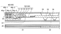
- FIG. 2A is a cross-sectional view of the imaging device provided at the distal end portion 31 of the endoscope 2 taken along a plane orthogonal to the substrate surface of the imaging device and parallel to the optical axis direction of incident light of the imaging device.
- FIG. 2B is a front view of the distal end portion 31 of the endoscope 2.
- the distal end portion 31 of the insertion portion 4 of the endoscope 2 and a part of the bending portion 32 are illustrated.
- the bending portion 32 is bendable in four directions, upward, downward, leftward, and rightward, as the bending wire inserted into the bending tube 34 is pulled and loosened.
- the imaging device 100 is provided at the upper portion inside the distal end portion 31 extended to the distal end side of the curved portion 32, and a treatment instrument channel 36 for extending various treatment instruments is formed at the lower portion.
- the imaging device 100 includes a lens unit 40 and an imaging unit 50 disposed on the proximal end side of the lens unit 40, and is adhered to the inside of the distal end portion 31 with an adhesive.
- the tip portion 31 is formed of a hard member for forming an internal space for housing the imaging device 100.
- the proximal outer periphery of the distal end portion 31 is covered by a flexible cladding tube (not shown).
- the member on the proximal side of the distal end portion 31 is formed of a flexible member so that the bending portion 32 can be bent.
- the lens unit 40 includes a plurality of objective lenses 40a-1 to 40a-3, spacers 40b-1 and 40b-2 disposed between the plurality of objective lenses 40a-1 to 40a-3, and a diaphragm member (not shown)
- the upper ends of the objective lens 40a-1 and the spacer 40b-1 are fixed to the distal end portion 31 by being fitted and fixed to the distal end fixing portion 35 inside the distal end portion 31.
- the outer diameter of the tip of the endoscope can be reduced by reducing the thickness of the imaging device 53.
- the imaging device 53 is a semiconductor and made of a brittle material such as single crystal silicon, The bending strength is significantly reduced.
- the imaging device 53 is supported by the distal end fixing portion 35 and the treatment tool channel 36, and the imaging device 53 is reinforced so as not to be broken by external stress or the like.
- the reinforcement of the imaging device 53 may be made by either the distal end fixing portion 35 or the treatment instrument channel 36, or may be made by another component of the distal end portion 31.
- the imaging unit 50 generates an electrical signal by receiving light reflected by the prism 51 that reflects light emitted from the objective lenses 40 a-1 to 40 a-3 of the lens unit 40 and light reflected by the prism 51.
- an imaging device 53 having a light receiving unit 52.
- the imaging device 53 is a horizontal type in which the light receiving unit 52 is disposed horizontally, and the prism 51 is bonded on the light receiving unit 52.
- the flexible printed circuit board 54 to which the signal cable 55 is connected is connected to the base end of the imaging device 53.
- Electronic components 57 for driving the imaging device 53 and the like are mounted on the flexible printed circuit 54.
- the imaging device 53 according to the embodiment of the present invention is a semiconductor imaging device of a charge coupled device (CCD) or a complementary metal oxide semiconductor (CMOS) type.
- CCD charge coupled device
- CMOS complementary metal oxide semiconductor
- the proximal end of the signal cable 55 extends in the proximal direction of the insertion portion 4.
- the signal cable 55 is inserted through the insertion portion 4 and extends to the connector 7 through the operation portion 5 and the universal cord 6 shown in FIG.
- the light incident on the front end portion 31 is condensed by the objective lenses 40 a-1 to 40 a-3 and is incident on the prism 51.
- the light receiving unit 52 receives the light emitted from the prism 51, and converts the received light into an imaging signal.
- the imaging signal is output to the processor 10 via the signal cable 55 connected to the flexible printed circuit 54 and the connector 7.
- the light incident side of the front end portion 31, that is, the side on which the objective lenses 40a-1 to 40a-3 are disposed is referred to as a front end
- the side on which the prism 51 is disposed is referred to as a rear end.
- the side surface of the imaging element 53 in contact with the inner wall surface of the tip fixing portion 35 is bonded to the inner wall surface of the tip fixing portion 35 with an adhesive as shown in FIG.
- the side is sealed by a sealing resin 67.
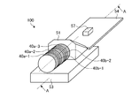
- FIG. 3A is a perspective view of the imaging device 100 shown in FIG. 2A.
- FIG. 3B is a cross-sectional view taken along line AA of FIG. 3A.
- the outer peripheries of the objective lenses 40a-1 to 40a-3 are directly mounted on the surface of the imaging element 53.
- the objective lenses 40a-1 to 40a-3 and the prism 51 constitute an imaging optical system, and an object image is formed on the light receiving portion 52 of the imaging element 53 by the imaging optical system.
- An imaging element electrode 56 for connecting the flexible printed circuit 54 is formed on the rear end side of the imaging element 53.
- the distance between the objective lenses 40a-1 to 40a-3 is adjusted by the spacers 40b-1 and 40b-2 to define the position, but the spacers 40b-1 and 40b-2
- the thickness in the optical axis direction of the lens is thinner than that of the objective lenses 40a-1 to 40a-3, and therefore, it is preferable to be integrated with any of the objective lenses 40a-1 to 40a-3.
- the objective lens 40 a-3 and the spacer 40 b-2, and the objective lens 40 a-2 and the spacer 40 b-1 be integrated and mounted at a predetermined position of the imaging device 53 for each integrated part.
- the diaphragm members (not shown) be integrated with any of the objective lenses 40a-1 to 40a-3.
- the integration of the objective lens and the spacer can be performed by moving the objective lens held by the jig onto the mounted spacer, aligning by image processing, and then bonding and integrating by an adhesive. .
- an optical path of incident light may be formed by etching or the like to form an objective lens in which the spacer is integrated.
- the imaging optical system can perform passive alignment to the surface of the imaging element 53 by image processing (so-called passive alignment). Furthermore, in order to align on the imaging device 53 with higher accuracy, the objective lens 40a-1 to 40a-3, the spacers 40b-1 and 40b-2, and the lens unit 40 including the aperture member are integrated as one unit. After that, it is preferable to perform so-called active alignment in which the position of the partial set is adjusted and the active alignment is performed while confirming the image output of the imaging device 53.
- an adhesive is applied in advance to the connecting surfaces of the objective lenses 40a-1 to 40a-3 or the spacers 40b-1 and 40b-2, and in the frame member for integration, for example, the objective lens 40a -3, Spacer 40b-2, Objective lens 40a-2, Spacer 40b-1, Objective lens 40a-1 and so on in that order and curing the adhesive, and then taking out the lens unit 40 from the frame member can do.
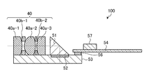
- the integrated lens unit 40 is held by a jig 58 or the like having a suction function, and is mounted on the image pickup device 53 to which the prism 51 is connected in advance on the light receiving unit 52.
- FIG. 4 is a diagram for explaining the manufacturing process of the imaging device 100. As shown in FIG. First, as shown in FIG. 4A, the integrated lens unit 40 is placed on the imaging device 53 in a state of being held by the jig 58. As shown in FIG. 4B, in a state where the lens unit 40 is held by the jig 58, the test chart 59 is imaged, and the image is input to the light receiving unit 52 through the lens unit 40.
- the image data converted into the electric signal by the light receiving unit 52 is output to the monitor 61 by bringing the probe 60 into contact with the imaging element electrode 56.
- Active alignment may be performed by adjusting the position of the lens unit 40 based on the image output to the monitor 61.
- the position of the lens unit 40 may be adjusted based on analysis by software or the like without outputting image data to the monitor 61 or the like. Since the alignment of the lens unit 40 is performed on the imaging device 53, not only positional adjustment of front and rear and left and right but also adjustment of the tilt angle is possible, and the position can be defined with high accuracy.
- the adhesive applied in advance to the connection portion with the imaging device 53 such as the objective lenses 40a-1 to 40a-3 is cured.
- the lens unit 40 can be connected on the surface of the imaging element 53.
- the surface of the imaging device 53 includes not only the silicon surface of the imaging device 53 main body but also thin film surfaces such as pixels and color filters formed on the silicon surface.
- the imaging device 100 can directly mount the objective lenses 40a-1 to 40a-3 on the imaging device 53 without using a frame member, so the imaging device 100 can be miniaturized. .
- the mounting position of the lens unit 40 is defined by active alignment, the position of the imaging optical system can be defined more accurately.
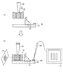
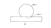
- FIG. 5A is a diagram for explaining an imaging device according to a first modification of the present embodiment.
- Flat portions 40c-1 to 40c-3 (flat portions 40c-2 and 40c-3 are not shown) are formed on a flat surface and can be formed by cutting off side portions of objective lenses 40a-1 to 40a-3. It is.
- the flat portions 40c-1 to 40c-3 the contact area with the surface of the imaging element 53 is increased, so that the positions of the objective lenses 40a-1 to 40a-3 can be defined simply and stably.
- the lens unit 40 can be simply and stably.
- the position of can be defined.
- a lens position defining member 62 may be provided on the image sensor 53 to define the positions of the objective lenses 40a-1 to 40a-3.
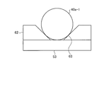
- FIG. 5B is a diagram for explaining an imaging device according to the second modification of the present embodiment.
- the lens position defining member 62 is made of a silicon block and has a groove 63 having a V-shaped vertical cross section.
- the lens position defining member 62 can form a V-shaped groove 63 by bonding a plate-like silicon block to the surface of the imaging element 53 and etching the bonded silicon block.
- the lens position defining member 62 forms a lens position defining member having a length approximately equal to or longer than the length in the optical axis direction of the lens unit 40 including the spacers 40b-1 and 40b-2.
- the position of the integrated lens unit 40 may be defined by the defining member 62.
- a plurality of lens position defining members corresponding to the objective lenses 40a-1 to 40a-3 are formed at the positions where the objective lenses 40a-1 to 40a-3 are to be mounted, and each of the objective lenses 40a-1 to 40a-3 is Position may be defined.
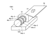
- FIG. 5C is a perspective view for describing an imaging device 100C according to the third modification of the present embodiment.
- the alignment marks 64a-1 to 64a-3 are formed on the imaging device 53C by photolithography or the like, and provided so as to correspond to the connection positions of the objective lenses 40a-1 to 40a-3.
- the objective lenses 40 a-1 to 40 a-3 are moved to the corresponding alignment marks 64 a-1 to 64 a-3 while the upper side surfaces of the objective lenses 40 a-1 to 40 a-3 are individually attracted by a jig or the like.
- the objective lenses 40a-1 to 40a-3 used in the third modification may have flat portions 40c-1 to 40c-3 formed thereon.
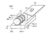
- FIG. 5D is a perspective view for explaining the lens position defining means of the imaging device 100D according to the fourth modification of the present embodiment.
- FIG. 5E is a cross-sectional view taken along line BB of FIG. 5D.
- the recesses 65a-1 to 65a-3 are formed by etching the thin film 66.
- the thin film 66 such as a color filter formed on the surface of the imaging device 53D has a thickness of about 10 ⁇ m, but the thin film 66 at the connection position of the objective lenses 40a-1 to 40a-3 is partially removed by etching Thus, the recesses 65a-1 to 65a-3 are formed. Even if the depth of the concave portion is about the thickness of the thin film 66, as shown in FIG. 5E, the positions are passive by fitting the objective lenses 40a-1 to 40a-3 to the concave portions 65a-1 to 65a-3. It is possible to define
- the front end surface of the objective lens 40a-1 is located behind the front end side surface of the imaging device, but the surface of the imaging device connected to the objective lens 40a-1 is within the viewing angle. It is preferable to be mounted in the position which does not enter.
- the front end surface of the objective lens 40a-1 is aligned with the front end side surface of the imaging device, but by arranging the front end surface of the objective lens 40a-1 in front of the front end side surface of the imaging device, When it is inserted into the distal end portion of an endoscope apparatus or the like and inserted into and fixed to the distal end fixing portion, it is easy to hold the inside in a liquid tight manner.
Abstract
Provided are a miniaturizable imaging device and an endoscope device. The imaging device (100) is characterized by being provided with: objective lenses (40a-1 to 40a-3) that gather incoming light; a prism (51) that reflects the light gathered by the objective lenses (40a-1 to 40a-3); and an imaging element (53) having a light reception unit (52) that generates an electric signal by receiving the light reflected by the prism (51) and performing photoelectric conversion. The imaging device (100) is further characterized in that the prism (51) is mounted above the light reception unit (52), and the objective lenses (40a-1 to 40a-3) are directly mounted to the surface of the imaging element (53).
Description
本発明は、被検体内に挿入される内視鏡の挿入部の先端に設けられて被検部位を撮像する撮像装置、および該撮像装置を使用した内視鏡装置に関する。
The present invention relates to an imaging device provided at the tip of an insertion portion of an endoscope to be inserted into a subject to image a region to be examined, and an endoscope apparatus using the imaging device.
従来、医療分野および工業分野において、各種検査のために内視鏡装置が広く用いられている。このうち、医療用の内視鏡装置は、患者等の被検体の体腔内に、先端部に撮像装置が内蔵された可撓性を有する細長の挿入部を挿入することによって、被検部位の観察等を行うことができるものであるが、被検体内への導入のしやすさを考慮し、挿入部の細径化が求められている。
Conventionally, an endoscope apparatus is widely used for various examinations in the medical field and the industrial field. Among them, the medical endoscope apparatus is configured such that a flexible elongated insertion portion having a built-in imaging device is inserted into a tip end portion of a body cavity of a subject such as a patient. Although observation etc. can be performed, the diameter reduction of an insertion part is calculated | required in consideration of the ease of introduction | transduction inside a subject.
一般に、内視鏡等に用いられる撮像装置は、金属製の枠部材によって対物光学系としてのレンズ群の外周部を保持し、レンズ群の径方向および光軸方向の位置を規定しているが、挿入部を細径化する技術として、対物光学系の枠部材を保持する部材に光路方向の間隔を設け、この間隔部分の外周面をカットした後、固体撮像素子の上面側に近接配置することにより、高さ寸法を低減した内視鏡用撮像装置が開示されている(たとえば、特許文献1および2参照)。
Generally, an imaging device used for an endoscope or the like holds the outer peripheral portion of a lens group as an objective optical system by a metal frame member, and defines the positions of the lens group in the radial direction and the optical axis direction. As a technique for reducing the diameter of the insertion portion, a member for holding the frame member of the objective optical system is provided with an interval in the optical path direction, and after cutting the outer peripheral surface of this interval portion, disposed close to the upper surface side of the solid-state imaging device Thus, an endoscope imaging device with a reduced height dimension is disclosed (see, for example, Patent Documents 1 and 2).
しかしながら、金属加工の限界により金属製の枠部材の肉厚を所定値以下とすることは困難であるため、特許文献1および2の技術では、対物光学系がさらに小型化された場合、対物光学系の外形寸法に比べ、枠部材の肉厚が相対的に大きくなり、撮像装置の小型化を阻害するおそれがある。また、枠部材の材質として樹脂を用いた場合であっても、枠部材の形成上(例えば、射出成型により枠部材を形成する場合)の限界により、金属製と同様に肉厚が制限され、小型化を阻害する要因となりうるものであった。
However, because it is difficult to make the thickness of the metal frame member equal to or less than a predetermined value due to the limit of metal processing, in the techniques of Patent Documents 1 and 2, when the objective optical system is further miniaturized, the objective optical The thickness of the frame member becomes relatively large compared to the external dimensions of the system, which may hinder the miniaturization of the imaging device. Further, even when resin is used as the material of the frame member, the thickness is limited in the same manner as metal, due to the limit in formation of the frame member (for example, when forming the frame member by injection molding), It could be a factor that impedes miniaturization.
本発明は、上記に鑑みてなされたものであって、小型化可能な撮像装置、および内視鏡装置を提供することを目的とする。
This invention is made in view of the above, Comprising: It aims at providing an imaging device which can be miniaturized, and an endoscope apparatus.
上述した課題を解決し、目的を達成するために、本発明にかかる撮像装置は、入射光を集光するレンズ群と、前記レンズ群が集光した光を反射させるプリズムと、前記プリズムにより反射された光を受光して光電変換を行うことにより電気信号を生成する受光部を有する撮像素子と、を備え、前記プリズムは前記受光部上に実装されるとともに、前記レンズ群は前記撮像素子表面に直接実装されることを特徴とする。
In order to solve the problems described above and to achieve the object, an imaging device according to the present invention includes a lens group that collects incident light, a prism that reflects light collected by the lens group, and reflection by the prism And an imaging device having a light receiving unit that generates an electric signal by receiving the received light and performing photoelectric conversion, the prism is mounted on the light receiving unit, and the lens group is provided on the surface of the imaging device It is characterized in that it is directly implemented in
また、本発明にかかる撮像装置は、上記発明において、前記撮像素子と接する前記レンズ群の底面に平面状をなす平坦部が形成されることを特徴とする。
In the imaging device according to the present invention as set forth in the invention described above, a flat portion having a planar shape is formed on the bottom surface of the lens group in contact with the imaging element.
また、本発明にかかる撮像装置は、上記発明において、前記撮像素子の表面上に、前記レンズ群の位置を規定するレンズ位置規定手段を有することを特徴とする。
In the imaging apparatus according to the present invention as set forth in the invention described above, the apparatus further comprises lens position defining means for defining the position of the lens group on the surface of the image sensor.
また、本発明にかかる撮像装置は、上記発明において、前記レンズ位置規定手段は、鉛直断面がV字状をなすシリコンブロックであることを特徴とする。
In the imaging apparatus according to the present invention as set forth in the invention described above, the lens position defining means is a silicon block having a V-shaped vertical cross section.
また、本発明にかかる撮像装置は、上記発明において、前記レンズ位置規定手段は、前記撮像素子表面に成膜された薄膜に形成された凹部であることを特徴とする。
In the imaging apparatus according to the present invention as set forth in the invention described above, the lens position defining means is a recess formed in a thin film formed on the surface of the imaging element.
また、本発明にかかる撮像装置は、上記発明において、前記レンズ位置規定手段は、前記撮像素子表面に形成されたアライメントマークであることを特徴とする。
In the image pickup apparatus according to the present invention as set forth in the above invention, the lens position defining means is an alignment mark formed on the surface of the image pickup element.
また、本発明にかかる撮像装置は、上記発明において、前記レンズ群は、絞り部材および間隔保持部材とともに一体化した部組とされ、前記撮像素子上に前記部組の位置を規定する際、前記部組から入力された画像情報をもとに前記部組の搭載位置を調整することを特徴とする。
Further, in the imaging device according to the present invention, in the above-mentioned invention, the lens group is a unitary body integrated with a diaphragm member and a spacing member, and when defining the position of the unitary group on the imaging device, The mounting position of the set is adjusted based on the image information input from the set.
また、本発明の内視鏡装置は、生体内に挿入され、生体内を撮像する撮像装置を備えた内視鏡装置において、前記撮像装置は、上記のいずれか一つに記載の撮像装置であることを特徴とする。
An endoscope apparatus according to the present invention is an endoscope apparatus including an imaging device which is inserted into a living body and images an inside of the living body, wherein the imaging device is the imaging device according to any one of the above. It is characterized by
また、本発明の内視鏡装置は、入射光を集光するレンズ群と、前記レンズ群が集光した光を反射させるプリズムと、前記プリズムにより反射された光を受光して光電変換を行うことにより電気信号を生成する受光部を有する撮像素子と、を備える撮像装置が挿入部の先端部に設けられ、前記挿入部を生体内に挿入して生体内情報を取得する内視鏡装置において、前記撮像素子は前記先端部の構成物によって支持されていることを特徴とする。
The endoscope apparatus according to the present invention performs photoelectric conversion by receiving a lens group that collects incident light, a prism that reflects the light collected by the lens group, and light that is reflected by the prism. And an imaging device having a light receiving unit that generates an electrical signal, wherein the imaging device is provided at the distal end of the insertion unit, and the endoscope is configured to insert the insertion unit into a living body to acquire in-vivo information. The image pickup device is characterized in that it is supported by a component of the tip portion.
本発明によれば、レンズ群を撮像素子表面に直接実装することにより、撮像装置の細径化および短小化を図ることが可能となる。
According to the present invention, by directly mounting the lens group on the surface of the imaging device, it is possible to achieve a reduction in diameter and a reduction in size of the imaging device.
以下の説明では、本発明を実施するための形態(以下、「実施の形態」という)として、撮像モジュールを備えた内視鏡装置について説明する。また、この実施の形態により、この発明が限定されるものではない。さらに、図面の記載において、同一部分には同一の符号を付している。さらにまた、図面は、模式的なものであり、各部材の厚みと幅との関係、各部材の比率等は、現実と異なることに留意する必要がある。また、図面の相互間においても、互いの寸法や比率が異なる部分が含まれている。
In the following description, an endoscope apparatus provided with an imaging module will be described as a mode for carrying out the present invention (hereinafter, referred to as "embodiment"). Further, the present invention is not limited by the embodiment. Furthermore, in the description of the drawings, the same parts are given the same reference numerals. Furthermore, it should be noted that the drawings are schematic, and the relationship between the thickness and width of each member, the ratio of each member, and the like are different from reality. In addition, among the drawings, there are included parts having different dimensions and ratios.
図1は、本発明の実施の形態にかかる内視鏡システムの全体構成を模式的に示す図である。図1に示すように、内視鏡装置1は、内視鏡2と、ユニバーサルコード6と、コネクタ7と、光源装置9と、プロセッサ(制御装置)10と、表示装置13とを備える。
FIG. 1 is a view schematically showing an entire configuration of an endoscope system according to an embodiment of the present invention. As shown in FIG. 1, the endoscope apparatus 1 includes an endoscope 2, a universal cord 6, a connector 7, a light source device 9, a processor (control device) 10, and a display device 13.
内視鏡2は、挿入部4を被検体の体腔内に挿入することによって、被検体の体内画像を撮像し撮像信号を出力する。ユニバーサルコード6内部の電気ケーブル束は、内視鏡2の挿入部4の先端まで延伸され、挿入部4の先端部31に設けられる撮像装置に接続する。
The endoscope 2 captures an in-vivo image of a subject by inserting the insertion unit 4 into a body cavity of the subject, and outputs an imaging signal. The electric cable bundle inside the universal cord 6 is extended to the tip of the insertion portion 4 of the endoscope 2 and connected to the imaging device provided at the tip portion 31 of the insertion portion 4.
コネクタ7は、ユニバーサルコード6の基端に設けられて、光源装置9およびプロセッサ10に接続され、ユニバーサルコード6と接続する先端部31の撮像装置が出力する撮像信号に所定の信号処理を施すとともに、撮像信号をアナログデジタル変換(A/D変換)して画像信号として出力する。
The connector 7 is provided at the base end of the universal cord 6, connected to the light source device 9 and the processor 10, and performs predetermined signal processing on the imaging signal output from the imaging device of the distal end 31 connected to the universal cord 6. The image pickup signal is analog-digital converted (A / D converted) and output as an image signal.
光源装置9は、例えば、白色LEDを用いて構成される。光源装置9が点灯するパルス状の白色光は、コネクタ7、ユニバーサルコード6を経由して内視鏡2の挿入部4の先端から被写体へ向けて照射する照明光となる。
The light source device 9 is configured using, for example, a white LED. The pulsed white light that the light source device 9 lights up becomes illumination light that is emitted toward the subject from the tip of the insertion portion 4 of the endoscope 2 via the connector 7 and the universal cord 6.
プロセッサ10は、コネクタ7から出力される画像信号に所定の画像処理を施すとともに、内視鏡装置1全体を制御する。表示装置13は、プロセッサ10が処理を施した画像信号を表示する。
The processor 10 performs predetermined image processing on the image signal output from the connector 7 and controls the entire endoscope apparatus 1. The display device 13 displays an image signal processed by the processor 10.
内視鏡2の挿入部4の基端側には、内視鏡機能を操作する各種ボタン類やノブ類が設けられた操作部5が接続される。操作部5には、被検体の体腔内に生体鉗子、電気メスおよび検査プローブ等の処置具を挿入する処置具挿入口17が設けられる。
The proximal end side of the insertion portion 4 of the endoscope 2 is connected to the operation unit 5 provided with various buttons and knobs for operating the endoscope function. The operation unit 5 is provided with a treatment instrument insertion port 17 for inserting a treatment instrument such as a biological forceps, an electric knife, and a test probe into a body cavity of a subject.
挿入部4は、撮像装置が設けられる先端部31と、先端部31の基端側に連設された複数方向に湾曲自在な湾曲部32と、この湾曲部32の基端側に連設された可撓管部33とによって構成される。湾曲部32内の湾曲管は、操作部5に設けられた湾曲操作用ノブの操作によって湾曲し、挿入部4内部に挿通された湾曲ワイヤの牽引弛緩にともない、たとえば上下左右の4方向に湾曲自在となっている。
The insertion portion 4 is connected to a distal end portion 31 provided with an imaging device, a bending portion 32 bendable in a plurality of directions continuously connected to the proximal end side of the distal end portion 31, and a proximal end side of the bending portion 32. And a flexible tube portion 33. The bending tube in the bending portion 32 is bent by the operation of a bending operation knob provided on the operation portion 5 and is bent in four directions, for example, in the upper, lower, left, and right directions along with the pulling and relaxing of the bending wire inserted into the insertion portion 4. It is free.
内視鏡2には、光源装置9からの照明光を伝送するライトガイド(不図示)が配設され、ライトガイドによる照明光の出射端に照明レンズ(不図示)が配置される。この照明レンズは、挿入部4の先端部31に設けられており、照明光が被検体に向けて照射される。
The endoscope 2 is provided with a light guide (not shown) for transmitting the illumination light from the light source device 9, and an illumination lens (not shown) is disposed at the emission end of the illumination light by the light guide. The illumination lens is provided at the distal end portion 31 of the insertion portion 4 and the illumination light is emitted toward the subject.
次に、内視鏡2の先端部31の構成について詳細に説明する。図2Aは、内視鏡2の先端部31に設けられた撮像装置の基板面に対して直交する面であって撮像装置の入射光の光軸方向と平行な面で切断した場合の断面図であり、図2Bは、内視鏡2の先端部31の前面図である。図2Aにおいては、内視鏡2の挿入部4の先端部31と、湾曲部32の一部を図示する。
Next, the configuration of the distal end portion 31 of the endoscope 2 will be described in detail. FIG. 2A is a cross-sectional view of the imaging device provided at the distal end portion 31 of the endoscope 2 taken along a plane orthogonal to the substrate surface of the imaging device and parallel to the optical axis direction of incident light of the imaging device. FIG. 2B is a front view of the distal end portion 31 of the endoscope 2. In FIG. 2A, the distal end portion 31 of the insertion portion 4 of the endoscope 2 and a part of the bending portion 32 are illustrated.
図2Aに示すように、湾曲部32は、湾曲管34内部に挿通された湾曲ワイヤの牽引弛緩にともない、上下左右の4方向に湾曲自在である。この湾曲部32の先端側に延設された先端部31内部の上部に、撮像装置100が設けられ、下部には各種処置具を延出させる処置具チャンネル36が形成されている。
As shown in FIG. 2A, the bending portion 32 is bendable in four directions, upward, downward, leftward, and rightward, as the bending wire inserted into the bending tube 34 is pulled and loosened. The imaging device 100 is provided at the upper portion inside the distal end portion 31 extended to the distal end side of the curved portion 32, and a treatment instrument channel 36 for extending various treatment instruments is formed at the lower portion.
撮像装置100は、レンズユニット40と、レンズユニット40の基端側に配置する撮像ユニット50とを有し、接着剤で先端部31の内側に接着される。先端部31は、撮像装置100を収容する内部空間を形成するための硬質部材で形成される。先端部31の基端外周部は、図示しない柔軟な被覆管によって被覆されている。先端部31よりも基端側の部材は、湾曲部32が湾曲可能なように、柔軟な部材で構成されている。
The imaging device 100 includes a lens unit 40 and an imaging unit 50 disposed on the proximal end side of the lens unit 40, and is adhered to the inside of the distal end portion 31 with an adhesive. The tip portion 31 is formed of a hard member for forming an internal space for housing the imaging device 100. The proximal outer periphery of the distal end portion 31 is covered by a flexible cladding tube (not shown). The member on the proximal side of the distal end portion 31 is formed of a flexible member so that the bending portion 32 can be bent.
レンズユニット40は、複数の対物レンズ40a-1~40a-3と、複数の対物レンズ40a-1~40a-3の間に配置されるスペーサ40b-1および40b-2と、図示しない絞り部材とを有し、この対物レンズ40a-1およびスペーサ40b-1の上端が、先端部31内部の先端固定部35に挿嵌固定されることによって、先端部31に固定される。このとき、撮像素子53の厚さを薄くすることにより、内視鏡先端の外径を細くすることができるが、撮像素子53は半導体であり、単結晶シリコン等の脆性材料からなるため、抗折強度が著しく低下する。そこで、本実施の形態では、撮像素子53が先端固定部35、および処置具チャンネル36によって支持されており、外部からの応力等によって撮像素子53が抗折することの無いように補強されている。なお、撮像素子53の補強は、先端固定部35、処置具チャンネル36のいずれかによるものでもよく、また、先端部31の他の構成物によるものでもよい。
The lens unit 40 includes a plurality of objective lenses 40a-1 to 40a-3, spacers 40b-1 and 40b-2 disposed between the plurality of objective lenses 40a-1 to 40a-3, and a diaphragm member (not shown) The upper ends of the objective lens 40a-1 and the spacer 40b-1 are fixed to the distal end portion 31 by being fitted and fixed to the distal end fixing portion 35 inside the distal end portion 31. At this time, the outer diameter of the tip of the endoscope can be reduced by reducing the thickness of the imaging device 53. However, since the imaging device 53 is a semiconductor and made of a brittle material such as single crystal silicon, The bending strength is significantly reduced. Therefore, in the present embodiment, the imaging device 53 is supported by the distal end fixing portion 35 and the treatment tool channel 36, and the imaging device 53 is reinforced so as not to be broken by external stress or the like. . The reinforcement of the imaging device 53 may be made by either the distal end fixing portion 35 or the treatment instrument channel 36, or may be made by another component of the distal end portion 31.
撮像ユニット50は、レンズユニット40の対物レンズ40a-1~40a-3から出射された光を反射させるプリズム51、プリズム51により反射された光を受光して光電変換を行うことにより電気信号を生成する受光部52を有する撮像素子53を備える。撮像素子53は、受光部52が水平となるように配置される横置き型であり、プリズム51は受光部52上に接着されている。撮像素子53の基端には、信号ケーブル55が接続されたフレキシブルプリント基板54が接続されている。フレキシブルプリント基板54上には、撮像素子53を駆動する電子部品57等が実装されている。本発明の実施の形態における撮像素子53は、CCD(Charge Coupled Device)またはCMOS(Complementary Metal Oxide Semiconductor)型の半導体撮像素子である。
The imaging unit 50 generates an electrical signal by receiving light reflected by the prism 51 that reflects light emitted from the objective lenses 40 a-1 to 40 a-3 of the lens unit 40 and light reflected by the prism 51. And an imaging device 53 having a light receiving unit 52. The imaging device 53 is a horizontal type in which the light receiving unit 52 is disposed horizontally, and the prism 51 is bonded on the light receiving unit 52. The flexible printed circuit board 54 to which the signal cable 55 is connected is connected to the base end of the imaging device 53. Electronic components 57 for driving the imaging device 53 and the like are mounted on the flexible printed circuit 54. The imaging device 53 according to the embodiment of the present invention is a semiconductor imaging device of a charge coupled device (CCD) or a complementary metal oxide semiconductor (CMOS) type.
信号ケーブル55の基端は、挿入部4の基端方向に延伸する。信号ケーブル55は、挿入部4に挿通配置され、図1に示す操作部5およびユニバーサルコード6を介して、コネクタ7まで延設されている。
The proximal end of the signal cable 55 extends in the proximal direction of the insertion portion 4. The signal cable 55 is inserted through the insertion portion 4 and extends to the connector 7 through the operation portion 5 and the universal cord 6 shown in FIG.
先端部31に入射した光は、対物レンズ40a-1~40a-3によって集光され、プリズム51に入射する。受光部52は、プリズム51から照射された光を受光し、受光した光を撮像信号に変換する。撮像信号は、フレキシブルプリント基板54に接続される信号ケーブル55およびコネクタ7を経由して、プロセッサ10に出力される。本明細書において、先端部31の光が入射する側、すなわち対物レンズ40a-1~40a-3が配置される側を前端部といい、プリズム51が配置される側を後端部という。
The light incident on the front end portion 31 is condensed by the objective lenses 40 a-1 to 40 a-3 and is incident on the prism 51. The light receiving unit 52 receives the light emitted from the prism 51, and converts the received light into an imaging signal. The imaging signal is output to the processor 10 via the signal cable 55 connected to the flexible printed circuit 54 and the connector 7. In the present specification, the light incident side of the front end portion 31, that is, the side on which the objective lenses 40a-1 to 40a-3 are disposed is referred to as a front end, and the side on which the prism 51 is disposed is referred to as a rear end.
先端固定部35の内壁面と接する撮像素子53の側面は、図2Bに示すように、接着剤で先端固定部35の内壁面に接着され、撮像素子53上のプリズム51の組み付け位置の後端側は、封止樹脂67により封止されている。
The side surface of the imaging element 53 in contact with the inner wall surface of the tip fixing portion 35 is bonded to the inner wall surface of the tip fixing portion 35 with an adhesive as shown in FIG. The side is sealed by a sealing resin 67.
次に、本実施の形態にかかる撮像装置100について説明する。図3Aは、図2Aに示す撮像装置100の斜視図である。図3Bは、図3AのA-A線断面図である。
Next, the imaging device 100 according to the present embodiment will be described. FIG. 3A is a perspective view of the imaging device 100 shown in FIG. 2A. FIG. 3B is a cross-sectional view taken along line AA of FIG. 3A.
図3Aおよび図3Bに示すように、本実施の形態にかかる撮像装置100において、対物レンズ40a-1~40a-3は、その外周が撮像素子53表面に直接実装されている。対物レンズ40a-1~40a-3、およびプリズム51により撮像光学系が構成され、該撮像光学系により撮像素子53の受光部52上に被写体像が結像される。
As shown in FIGS. 3A and 3B, in the imaging device 100 according to the present embodiment, the outer peripheries of the objective lenses 40a-1 to 40a-3 are directly mounted on the surface of the imaging element 53. The objective lenses 40a-1 to 40a-3 and the prism 51 constitute an imaging optical system, and an object image is formed on the light receiving portion 52 of the imaging element 53 by the imaging optical system.
撮像素子53の後端部側には、フレキシブルプリント基板54を接続する撮像素子電極56が形成されている。
An imaging element electrode 56 for connecting the flexible printed circuit 54 is formed on the rear end side of the imaging element 53.
本実施の形態にかかる撮像装置100では、スペーサ40b-1および40b-2により対物レンズ40a-1~40a-3間の間隔を調整し、位置を規定するが、スペーサ40b-1および40b-2の光軸方向の厚さは、対物レンズ40a-1~40a-3に比べて薄いため、対物レンズ40a-1~40a-3のいずれかと一体化されることが好ましい。例えば、対物レンズ40a-3とスペーサ40b-2、対物レンズ40a-2とスペーサ40b-1とを一体化し、一体化されたパーツ毎に撮像素子53の所定位置に搭載することが好ましい。図示しない絞り部材もスペーサ40b-1および40b-2と同様に、対物レンズ40a-1~40a-3のいずれかと一体化されることが好ましい。対物レンズとスペーサの一体化は、載置されたスペーサ上に、治具により保持された対物レンズを移動させ、画像処理により位置合わせをした後、接着剤により接着して一体化することができる。あるいは、対物レンズの片面に、スペーサとなる金属皮膜を所望の厚さに形成した後、入射光の光路をエッチング等により形成して、スペーサが一体化された対物レンズとしてもよい。
In the imaging device 100 according to the present embodiment, the distance between the objective lenses 40a-1 to 40a-3 is adjusted by the spacers 40b-1 and 40b-2 to define the position, but the spacers 40b-1 and 40b-2 The thickness in the optical axis direction of the lens is thinner than that of the objective lenses 40a-1 to 40a-3, and therefore, it is preferable to be integrated with any of the objective lenses 40a-1 to 40a-3. For example, it is preferable that the objective lens 40 a-3 and the spacer 40 b-2, and the objective lens 40 a-2 and the spacer 40 b-1 be integrated and mounted at a predetermined position of the imaging device 53 for each integrated part. Similarly to the spacers 40b-1 and 40b-2, it is preferable that the diaphragm members (not shown) be integrated with any of the objective lenses 40a-1 to 40a-3. The integration of the objective lens and the spacer can be performed by moving the objective lens held by the jig onto the mounted spacer, aligning by image processing, and then bonding and integrating by an adhesive. . Alternatively, after forming a metal film to be a spacer to a desired thickness on one side of the objective lens, an optical path of incident light may be formed by etching or the like to form an objective lens in which the spacer is integrated.
このように撮像光学系は、撮像素子53の表面へと画像処理による受動的な位置合わせを行うことができる(いわゆるパッシブアライメント)。さらに、より高精度に撮像素子53上にアライメントするためには、対物レンズ40a-1~40a-3、スペーサ40b-1および40b-2ならびに絞り部材からなるレンズユニット40を1つの部組として一体化した後、撮像素子53の画像出力を確認しながら部組の位置を調整して能動的にアライメントする、いわゆるアクティブアライメントを行うことが好ましい。
As described above, the imaging optical system can perform passive alignment to the surface of the imaging element 53 by image processing (so-called passive alignment). Furthermore, in order to align on the imaging device 53 with higher accuracy, the objective lens 40a-1 to 40a-3, the spacers 40b-1 and 40b-2, and the lens unit 40 including the aperture member are integrated as one unit. After that, it is preferable to perform so-called active alignment in which the position of the partial set is adjusted and the active alignment is performed while confirming the image output of the imaging device 53.
レンズユニット40は、対物レンズ40a-1~40a-3またはスペーサ40b-1および40b-2の接続面に予め接着剤を塗布しておき、一体化用の枠部材中に、例えば、対物レンズ40a-3、スペーサ40b-2、対物レンズ40a-2、スペーサ40b-1、対物レンズ40a-1等の順番に落とし込み、接着剤を硬化させた後、枠部材からレンズユニット40を取り出すことで一体化することができる。
In the lens unit 40, an adhesive is applied in advance to the connecting surfaces of the objective lenses 40a-1 to 40a-3 or the spacers 40b-1 and 40b-2, and in the frame member for integration, for example, the objective lens 40a -3, Spacer 40b-2, Objective lens 40a-2, Spacer 40b-1, Objective lens 40a-1 and so on in that order and curing the adhesive, and then taking out the lens unit 40 from the frame member can do.
一体化されたレンズユニット40は、吸着機能を有する治具58等に保持され、受光部52上にプリズム51が予め接続された撮像素子53上に載置される。図4は、撮像装置100の製造工程を説明する図である。まず、図4(a)に示すように、一体化されたレンズユニット40は、治具58により保持された状態で、撮像素子53上に載置される。図4(b)に示すように、レンズユニット40が治具58に保持された状態で、テストチャート59が撮像され、その画像はレンズユニット40を通じて受光部52へと入力される。受光部52により電気信号に変換された画像データは、プローブ60を撮像素子電極56に当接することにより、モニタ61に出力される。このモニタ61に出力された画像にもとづいてレンズユニット40の位置を調整することにより、アクティブアライメントを行えばよい。アクティブアライメントは、画像データをモニタ61等に出力することなく、ソフトウェア等による解析にもとづいてレンズユニット40の位置を調整してもよい。レンズユニット40のアライメントは、撮像素子53上で行われるため、前後および左右の位置調整のみならず、チルト角の調整も可能で、高精度に位置を規定することができる。
The integrated lens unit 40 is held by a jig 58 or the like having a suction function, and is mounted on the image pickup device 53 to which the prism 51 is connected in advance on the light receiving unit 52. FIG. 4 is a diagram for explaining the manufacturing process of the imaging device 100. As shown in FIG. First, as shown in FIG. 4A, the integrated lens unit 40 is placed on the imaging device 53 in a state of being held by the jig 58. As shown in FIG. 4B, in a state where the lens unit 40 is held by the jig 58, the test chart 59 is imaged, and the image is input to the light receiving unit 52 through the lens unit 40. The image data converted into the electric signal by the light receiving unit 52 is output to the monitor 61 by bringing the probe 60 into contact with the imaging element electrode 56. Active alignment may be performed by adjusting the position of the lens unit 40 based on the image output to the monitor 61. In active alignment, the position of the lens unit 40 may be adjusted based on analysis by software or the like without outputting image data to the monitor 61 or the like. Since the alignment of the lens unit 40 is performed on the imaging device 53, not only positional adjustment of front and rear and left and right but also adjustment of the tilt angle is possible, and the position can be defined with high accuracy.
上記のようにして、レンズユニット40を撮像素子53上に直接アライメントした後、あらかじめ対物レンズ40a-1~40a-3等の撮像素子53との接続部分に塗布しておいた接着剤を硬化することにより、レンズユニット40を撮像素子53表面上に接続することができる。なお、本明細書において、撮像素子53の表面とは、撮像素子53本体部を構成するシリコン表面のほか、該シリコン表面に形成された画素やカラーフィルタ等の薄膜表面を含むものとする。
As described above, after the lens unit 40 is directly aligned on the imaging device 53, the adhesive applied in advance to the connection portion with the imaging device 53 such as the objective lenses 40a-1 to 40a-3 is cured. Thus, the lens unit 40 can be connected on the surface of the imaging element 53. In the present specification, the surface of the imaging device 53 includes not only the silicon surface of the imaging device 53 main body but also thin film surfaces such as pixels and color filters formed on the silicon surface.
本実施の形態にかかる撮像装置100は、枠部材を使用することなく対物レンズ40a-1~40a-3を撮像素子53に直接実装することができるため、撮像装置100を小型化することができる。また、レンズユニット40の実装位置を、アクティブアライメントにより規定するため、より高精度に撮像光学系の位置を規定することが可能となる。
The imaging device 100 according to the present embodiment can directly mount the objective lenses 40a-1 to 40a-3 on the imaging device 53 without using a frame member, so the imaging device 100 can be miniaturized. . In addition, since the mounting position of the lens unit 40 is defined by active alignment, the position of the imaging optical system can be defined more accurately.
また、対物レンズ40a-1~40a-3の撮像素子53へのアライメントを容易にするために、撮像素子53と接する対物レンズ40a-1~40a-3の側面部分に平坦部40c-1~40c-3を形成してもよい。図5Aは、本実施の形態の変形例1にかかる撮像装置を説明する図である。平坦部40c-1~40c-3(平坦部40c-2および40c-3は図示せず)は、平面上をなし、対物レンズ40a-1~40a-3の側面部分を切除することにより形成可能である。平坦部40c-1~40c-3を形成することにより、撮像素子53の表面との接触面積が増加するため、簡易、かつ安定的に対物レンズ40a-1~40a-3の位置を規定することができる。なお、平坦部40c-1~40c-3を設けることにより、対物レンズ40a-1~40a-3をスペーサ40b-1、40b-2とともに一体化した場合にも、簡易かつ安定してレンズユニット40の位置を規定することができる。
Also, in order to facilitate alignment of the objective lenses 40a-1 to 40a-3 with the imaging device 53, flat portions 40c-1 to 40c are provided on side portions of the objective lenses 40a-1 to 40a-3 in contact with the imaging device 53. -3 may be formed. FIG. 5A is a diagram for explaining an imaging device according to a first modification of the present embodiment. Flat portions 40c-1 to 40c-3 (flat portions 40c-2 and 40c-3 are not shown) are formed on a flat surface and can be formed by cutting off side portions of objective lenses 40a-1 to 40a-3. It is. By forming the flat portions 40c-1 to 40c-3, the contact area with the surface of the imaging element 53 is increased, so that the positions of the objective lenses 40a-1 to 40a-3 can be defined simply and stably. Can. Incidentally, even when the objective lenses 40a-1 to 40a-3 are integrated with the spacers 40b-1 and 40b-2 by providing the flat portions 40c-1 to 40c-3, the lens unit 40 can be simply and stably. The position of can be defined.
さらに、撮像素子53上に、対物レンズ40a-1~40a-3の位置を規定するレンズ位置規定部材62を設けてもよい。図5Bは、本実施の形態の変形例2にかかる撮像装置を説明する図である。レンズ位置規定部材62は、シリコンブロックからなり、鉛直断面がV字状をなす溝部63を有する。レンズ位置規定部材62は、板状のシリコンブロックを撮像素子53表面に接着し、接着したシリコンブロックをエッチングすることにより、V字状の溝部63を形成することができる。レンズ位置規定部材62は、スペーサ40b-1、40b-2を含んだレンズユニット40の光軸方向の長さと同程度、またはそれ以上の長さのレンズ位置規定部材を形成して、このレンズ位置規定部材62により、一体化したレンズユニット40の位置を規定してもよい。あるいは、対物レンズ40a-1~40a-3を載置する位置に、対物レンズ40a-1~40a-3に対応したレンズ位置規定部材を複数形成して、対物レンズ40a-1~40a-3毎に位置を規定してもよい。
Furthermore, a lens position defining member 62 may be provided on the image sensor 53 to define the positions of the objective lenses 40a-1 to 40a-3. FIG. 5B is a diagram for explaining an imaging device according to the second modification of the present embodiment. The lens position defining member 62 is made of a silicon block and has a groove 63 having a V-shaped vertical cross section. The lens position defining member 62 can form a V-shaped groove 63 by bonding a plate-like silicon block to the surface of the imaging element 53 and etching the bonded silicon block. The lens position defining member 62 forms a lens position defining member having a length approximately equal to or longer than the length in the optical axis direction of the lens unit 40 including the spacers 40b-1 and 40b-2. The position of the integrated lens unit 40 may be defined by the defining member 62. Alternatively, a plurality of lens position defining members corresponding to the objective lenses 40a-1 to 40a-3 are formed at the positions where the objective lenses 40a-1 to 40a-3 are to be mounted, and each of the objective lenses 40a-1 to 40a-3 is Position may be defined.
さらにまた、撮像素子上に形成するレンズ位置規定手段は、アライメントマークであってもよい。図5Cは、本実施の形態の変形例3にかかる撮像装置100Cを説明する斜視図である。アライメントマーク64a-1~64a-3は、フォトリソグラフィ等により撮像素子53C上に形成され、対物レンズ40a-1~40a-3の接続位置に対応するように設けられる。対物レンズ40a-1~40a-3は、個々に治具等により上部側面を吸着された状態で、対応するアライメントマーク64a-1~64a-3に移動され、上部から対物レンズ40a-1~40a-3とレンズ位置規定手段であるアライメントマーク64a-1~64a-3との位置をカメラ等により確認しながら、受動的に位置調整が行われた後に撮像素子53上に固定される。変形例3で用いる対物レンズ40a-1~40a-3は、平坦部40c-1~40c-3が形成されたものであってもよい。
Furthermore, the lens position defining means formed on the imaging device may be an alignment mark. FIG. 5C is a perspective view for describing an imaging device 100C according to the third modification of the present embodiment. The alignment marks 64a-1 to 64a-3 are formed on the imaging device 53C by photolithography or the like, and provided so as to correspond to the connection positions of the objective lenses 40a-1 to 40a-3. The objective lenses 40 a-1 to 40 a-3 are moved to the corresponding alignment marks 64 a-1 to 64 a-3 while the upper side surfaces of the objective lenses 40 a-1 to 40 a-3 are individually attracted by a jig or the like. It is fixed on the image pickup device 53 after the position adjustment is performed passively while the positions of the alignment mark -3 and the alignment marks 64a-1 to 64a-3 which are lens position defining means are confirmed by a camera or the like. The objective lenses 40a-1 to 40a-3 used in the third modification may have flat portions 40c-1 to 40c-3 formed thereon.
また、撮像素子上に形成するレンズ位置規定手段は、撮像素子表面に形成されたカラーフィルタ等の薄膜に形成された凹部であってもよい。図5Dは、本実施の形態の変形例4にかかる撮像装置100Dのレンズ位置規定手段を説明する斜視図である。図5Eは、図5DのB-B線断面図である。
Further, the lens position defining means formed on the imaging device may be a concave portion formed on a thin film such as a color filter formed on the surface of the imaging device. FIG. 5D is a perspective view for explaining the lens position defining means of the imaging device 100D according to the fourth modification of the present embodiment. FIG. 5E is a cross-sectional view taken along line BB of FIG. 5D.
凹部65a-1~65a-3は、薄膜66をエッチングすることにより形成される。一般に、撮像素子53D表面に形成されるカラーフィルタ等の薄膜66は、その厚さが10μm程度であるが、対物レンズ40a-1~40a-3の接続位置の薄膜66を、エッチングにより一部除去して凹部65a-1~65a-3を形成する。深さが薄膜66の厚み程度の凹部であっても、図5Eに示すように、凹部65a-1~65a-3に対物レンズ40a-1~40a-3を嵌め合わせることにより、その位置を受動的に規定することが可能となる。
The recesses 65a-1 to 65a-3 are formed by etching the thin film 66. Generally, the thin film 66 such as a color filter formed on the surface of the imaging device 53D has a thickness of about 10 μm, but the thin film 66 at the connection position of the objective lenses 40a-1 to 40a-3 is partially removed by etching Thus, the recesses 65a-1 to 65a-3 are formed. Even if the depth of the concave portion is about the thickness of the thin film 66, as shown in FIG. 5E, the positions are passive by fitting the objective lenses 40a-1 to 40a-3 to the concave portions 65a-1 to 65a-3. It is possible to define
なお、変形例3および4では、対物レンズ40a-1の前端面は、撮像素子の前端側面より後ろに位置しているが、対物レンズ40a-1は、接続される撮像素子表面が視野角内に入らない位置に実装されることが好ましい。また、その他の例では、対物レンズ40a-1の前端面を撮像素子の前端側面に合わせているが、対物レンズ40a-1の前端面を、撮像素子の前端側面より前に配置することにより、内視鏡装置等の先端部内に挿入され、先端固定部に挿嵌固定された際、内部の液密の保持が容易となる。
In the third and fourth modifications, the front end surface of the objective lens 40a-1 is located behind the front end side surface of the imaging device, but the surface of the imaging device connected to the objective lens 40a-1 is within the viewing angle. It is preferable to be mounted in the position which does not enter. In other examples, the front end surface of the objective lens 40a-1 is aligned with the front end side surface of the imaging device, but by arranging the front end surface of the objective lens 40a-1 in front of the front end side surface of the imaging device, When it is inserted into the distal end portion of an endoscope apparatus or the like and inserted into and fixed to the distal end fixing portion, it is easy to hold the inside in a liquid tight manner.
1 内視鏡装置
2 内視鏡
4 挿入部
5 操作部
6 ユニバーサルコード
7 コネクタ
9 光源装置
10 プロセッサ
13 表示装置
17 処置具挿入口
31 先端部
32 湾曲部
33 可撓管部
34 湾曲管
35 先端固定部
36 処置具チャンネル
40 レンズユニット
40a-1~40a-3 対物レンズ
40b-1、40-b-2 スペーサ
40c-1~40c-3 平坦部
50 撮像ユニット
51 プリズム
52 受光部
53、53C、53D 撮像素子
54 フレキシブルプリント基板
55 信号ケーブル
56 撮像素子電極
57 電子部品
58 治具
59 テストチャート
60 プローブ
61 モニタ
62 レンズ位置規定部材
63 溝部
64a-1~64a-3 アライメントマーク
65a-1~65a-3 凹部
66 薄膜
67 封止樹脂
100、100C、100D 撮像装置 DESCRIPTION OFSYMBOLS 1 endoscope apparatus 2 endoscope 4 insertion part 5 operation part 6 universal code 7 connector 9 light source device 10 processor 13 display 17 treatment tool insertion port 31 tip part 32 curved part 33 flexible tube part 34 curved tube 35 tip fixed Part 36 Treatment tool channel 40 Lens unit 40a-1 to 40a-3 Objective lens 40b-1, 40-b-2 Spacer 40c-1 to 40c-3 Flat part 50 Imaging unit 51 Prism 52 Light receiving part 53, 53C, 53D Imaging Element 54 Flexible printed circuit board 55 Signal cable 56 Imaging element electrode 57 Electronic component 58 Jig 59 59 Test chart 60 Probe 61 Monitor 62 Lens position defining member 63 Groove 64a-1 to 64a-3 Alignment mark 65a-1 to 65a-3 Recess 66 Thin film 67 sealing resin 100, 1 00C, 100D imaging device
2 内視鏡
4 挿入部
5 操作部
6 ユニバーサルコード
7 コネクタ
9 光源装置
10 プロセッサ
13 表示装置
17 処置具挿入口
31 先端部
32 湾曲部
33 可撓管部
34 湾曲管
35 先端固定部
36 処置具チャンネル
40 レンズユニット
40a-1~40a-3 対物レンズ
40b-1、40-b-2 スペーサ
40c-1~40c-3 平坦部
50 撮像ユニット
51 プリズム
52 受光部
53、53C、53D 撮像素子
54 フレキシブルプリント基板
55 信号ケーブル
56 撮像素子電極
57 電子部品
58 治具
59 テストチャート
60 プローブ
61 モニタ
62 レンズ位置規定部材
63 溝部
64a-1~64a-3 アライメントマーク
65a-1~65a-3 凹部
66 薄膜
67 封止樹脂
100、100C、100D 撮像装置 DESCRIPTION OF
Claims (9)
- 入射光を集光するレンズ群と、
前記レンズ群が集光した光を反射させるプリズムと、
前記プリズムにより反射された光を受光して光電変換を行うことにより電気信号を生成する受光部を有する撮像素子と、
を備え、前記プリズムは前記受光部上に実装されるとともに、前記レンズ群は前記撮像素子表面に直接実装されることを特徴とする撮像装置。 A lens group that collects incident light;
A prism for reflecting the light collected by the lens group;
An image pickup device having a light receiving unit that generates an electric signal by receiving light reflected by the prism and performing photoelectric conversion;
And the lens group is mounted directly on the surface of the imaging device. - 前記撮像素子と接する前記レンズ群の底面に平面状をなす平坦部が形成されることを特徴とする請求項1に記載の撮像装置。 The imaging device according to claim 1, wherein a flat portion having a planar shape is formed on a bottom surface of the lens group in contact with the imaging element.
- 前記撮像素子の表面上に、前記レンズ群の位置を規定するレンズ位置規定手段を有することを特徴とする請求項1または2に記載の撮像装置。 3. The image pickup apparatus according to claim 1, further comprising lens position specifying means for specifying the position of the lens group on the surface of the image pickup element.
- 前記レンズ位置規定手段は、鉛直断面がV字状をなすシリコンブロックであることを特徴とする請求項3に記載の撮像装置。 4. The image pickup apparatus according to claim 3, wherein the lens position defining unit is a silicon block having a V-shaped vertical cross section.
- 前記レンズ位置規定手段は、前記撮像素子表面に成膜された薄膜に形成された凹部であることを特徴とする請求項3に記載の撮像装置。 4. The image pickup apparatus according to claim 3, wherein the lens position defining unit is a concave portion formed in a thin film formed on the surface of the image pickup element.
- 前記レンズ位置規定手段は、前記撮像素子表面に形成されたアライメントマークであることを特徴とする請求項3に記載の撮像装置。 4. The image pickup apparatus according to claim 3, wherein the lens position defining unit is an alignment mark formed on the surface of the image pickup element.
- 前記レンズ群は、絞り部材および間隔保持部材とともに一体化した部組とされ、前記撮像素子上に前記部組の位置を規定する際、前記部組から入力された画像情報をもとに前記部組の搭載位置を調整することを特徴とする請求項1または2に記載の撮像装置。 The lens group is a unitary body integrated with a diaphragm member and a spacing member, and when the position of the unitary group is defined on the imaging device, the unit is based on image information input from the unitary unit. The imaging device according to claim 1, wherein the mounting position of the set is adjusted.
- 生体内に挿入され、生体内を撮像する撮像装置を備えた内視鏡装置において、
前記撮像装置は、請求項1~7のいずれか一つに記載の撮像装置であることを特徴とする内視鏡装置。 An endoscope apparatus including an imaging device inserted into a living body and imaging an inside of the living body,
An endoscope apparatus characterized in that the imaging device is the imaging device according to any one of claims 1 to 7. - 入射光を集光するレンズ群と、
前記レンズ群が集光した光を反射させるプリズムと、
前記プリズムにより反射された光を受光して光電変換を行うことにより電気信号を生成する受光部を有する撮像素子と、
を備える撮像装置が挿入部の先端部に設けられ、前記挿入部を生体内に挿入して生体内情報を取得する内視鏡装置において、
前記撮像素子は前記先端部の構成物によって支持されていることを特徴とする内視鏡装置。 A lens group that collects incident light;
A prism for reflecting the light collected by the lens group;
An image pickup device having a light receiving unit that generates an electric signal by receiving light reflected by the prism and performing photoelectric conversion;
An endoscope apparatus including an imaging device provided at a distal end portion of an insertion unit, and inserting the insertion unit into a living body to acquire in-vivo information;
An endoscope apparatus characterized in that the imaging element is supported by a component of the distal end portion.
Priority Applications (3)
| Application Number | Priority Date | Filing Date | Title |
|---|---|---|---|
| DE112015001102.1T DE112015001102T5 (en) | 2014-03-03 | 2015-02-20 | Imaging device and endoscope device |
| CN201580011337.5A CN106793916A (en) | 2014-03-03 | 2015-02-20 | Camera head and endoscope apparatus |
| US15/227,352 US10542874B2 (en) | 2014-03-03 | 2016-08-03 | Imaging device and endoscope device |
Applications Claiming Priority (2)
| Application Number | Priority Date | Filing Date | Title |
|---|---|---|---|
| JP2014-041041 | 2014-03-03 | ||
| JP2014041041A JP6329394B2 (en) | 2014-03-03 | 2014-03-03 | Imaging apparatus and endoscope apparatus |
Related Child Applications (1)
| Application Number | Title | Priority Date | Filing Date |
|---|---|---|---|
| US15/227,352 Continuation US10542874B2 (en) | 2014-03-03 | 2016-08-03 | Imaging device and endoscope device |
Publications (1)
| Publication Number | Publication Date |
|---|---|
| WO2015133299A1 true WO2015133299A1 (en) | 2015-09-11 |
Family
ID=54055109
Family Applications (1)
| Application Number | Title | Priority Date | Filing Date |
|---|---|---|---|
| PCT/JP2015/054841 WO2015133299A1 (en) | 2014-03-03 | 2015-02-20 | Imaging device and endoscope device |
Country Status (5)
| Country | Link |
|---|---|
| US (1) | US10542874B2 (en) |
| JP (1) | JP6329394B2 (en) |
| CN (1) | CN106793916A (en) |
| DE (1) | DE112015001102T5 (en) |
| WO (1) | WO2015133299A1 (en) |
Families Citing this family (3)
| Publication number | Priority date | Publication date | Assignee | Title |
|---|---|---|---|---|
| CN107533205A (en) | 2015-05-12 | 2018-01-02 | 奥林巴斯株式会社 | The manufacture method of camera device, endoscopic system and camera device |
| WO2018061564A1 (en) * | 2016-09-30 | 2018-04-05 | シャープ株式会社 | Imaging device |
| CN111856742B (en) * | 2020-06-22 | 2023-06-20 | 杭州汇桐泽瑞医疗科技有限公司 | Hard tube endoscope |
Citations (3)
| Publication number | Priority date | Publication date | Assignee | Title |
|---|---|---|---|---|
| JPS6235314U (en) * | 1985-08-16 | 1987-03-02 | ||
| JPH0320312U (en) * | 1989-07-10 | 1991-02-27 | ||
| JP2009268639A (en) * | 2008-05-02 | 2009-11-19 | Olympus Corp | Capsule type endoscope |
Family Cites Families (12)
| Publication number | Priority date | Publication date | Assignee | Title |
|---|---|---|---|---|
| US5051823A (en) * | 1988-01-28 | 1991-09-24 | Fuji Optical Systems, Inc. | Dental instrument including laser device and electronic video dental camera |
| CN1122925A (en) * | 1994-11-07 | 1996-05-22 | 颜艮山 | Instant look mouse scanner |
| JP3668638B2 (en) * | 1999-03-23 | 2005-07-06 | フジノン株式会社 | Endoscopic imaging device |
| JP2002045333A (en) | 2000-08-01 | 2002-02-12 | Fuji Photo Optical Co Ltd | Endoscopic photographing device |
| JP2003153853A (en) * | 2001-11-22 | 2003-05-27 | Olympus Optical Co Ltd | Endoscope |
| WO2006080015A2 (en) * | 2005-01-27 | 2006-08-03 | Super Dimension Ltd. | Endoscope with miniature imaging arrangement |
| US8823859B2 (en) * | 2008-10-08 | 2014-09-02 | Olympus Corporation | Image pickup unit, optical unit, and manufacturing method for the image pickup unit |
| CN102711583B (en) * | 2010-02-01 | 2014-10-01 | 奥林巴斯医疗株式会社 | Image pickup unit for endoscope |
| JP5436470B2 (en) * | 2011-01-31 | 2014-03-05 | 富士フイルム株式会社 | Imaging device and electronic endoscope provided with the same |
| JP5547118B2 (en) * | 2011-03-03 | 2014-07-09 | 富士フイルム株式会社 | Image acquisition device and method of operating image acquisition device |
| JP6210656B2 (en) * | 2011-06-08 | 2017-10-11 | オリンパス株式会社 | Imaging device |
| US20160213236A1 (en) * | 2013-08-26 | 2016-07-28 | King Systems Corporation | Visualization instrument |
-
2014
- 2014-03-03 JP JP2014041041A patent/JP6329394B2/en active Active
-
2015
- 2015-02-20 CN CN201580011337.5A patent/CN106793916A/en active Pending
- 2015-02-20 WO PCT/JP2015/054841 patent/WO2015133299A1/en active Application Filing
- 2015-02-20 DE DE112015001102.1T patent/DE112015001102T5/en not_active Withdrawn
-
2016
- 2016-08-03 US US15/227,352 patent/US10542874B2/en active Active
Patent Citations (3)
| Publication number | Priority date | Publication date | Assignee | Title |
|---|---|---|---|---|
| JPS6235314U (en) * | 1985-08-16 | 1987-03-02 | ||
| JPH0320312U (en) * | 1989-07-10 | 1991-02-27 | ||
| JP2009268639A (en) * | 2008-05-02 | 2009-11-19 | Olympus Corp | Capsule type endoscope |
Also Published As
| Publication number | Publication date |
|---|---|
| US10542874B2 (en) | 2020-01-28 |
| US20160338574A1 (en) | 2016-11-24 |
| CN106793916A (en) | 2017-05-31 |
| DE112015001102T5 (en) | 2016-12-01 |
| JP2015165847A (en) | 2015-09-24 |
| JP6329394B2 (en) | 2018-05-23 |
Similar Documents
| Publication | Publication Date | Title |
|---|---|---|
| US8917315B2 (en) | Imaging module | |
| EP2777481B1 (en) | Image pickup unit and image pickup module | |
| US10084947B2 (en) | Imaging module | |
| CN106886088B (en) | Endoscope with a detachable handle | |
| US10437040B2 (en) | Imaging device and endoscope device | |
| US20090237497A1 (en) | Endoscope camera head and method for manufacturing the same | |
| WO2015133299A1 (en) | Imaging device and endoscope device | |
| US10416438B2 (en) | Imaging device for imaging inside of subject and endoscope device using the same | |
| US10739576B2 (en) | Imaging apparatus, endoscopic system, and imaging apparatus manufacturing method | |
| JP6137824B2 (en) | Imaging unit, endoscope apparatus, and manufacturing method of imaging unit | |
| WO2019193911A1 (en) | Imaging unit and endoscope | |
| JP6529703B2 (en) | Imaging unit and endoscope | |
| WO2017072861A1 (en) | Imaging device and endoscope | |
| WO2018079070A1 (en) | Endoscope | |
| JP5877231B2 (en) | Imaging module | |
| JP2019050508A (en) | Stereoscopic imaging apparatus and stereoscopic endoscope | |
| JP6617206B2 (en) | Endoscope | |
| JP2012179306A (en) | Imaging unit and endoscope |
Legal Events
| Date | Code | Title | Description |
|---|---|---|---|
| 121 | Ep: the epo has been informed by wipo that ep was designated in this application |
Ref document number: 15758341 Country of ref document: EP Kind code of ref document: A1 |
|
| WWE | Wipo information: entry into national phase |
Ref document number: 112015001102 Country of ref document: DE |
|
| 122 | Ep: pct application non-entry in european phase |
Ref document number: 15758341 Country of ref document: EP Kind code of ref document: A1 |