JP5877231B2 - Imaging module - Google Patents

Imaging module Download PDF

Info

Publication number
JP5877231B2
JP5877231B2 JP2014185889A JP2014185889A JP5877231B2 JP 5877231 B2 JP5877231 B2 JP 5877231B2 JP 2014185889 A JP2014185889 A JP 2014185889A JP 2014185889 A JP2014185889 A JP 2014185889A JP 5877231 B2 JP5877231 B2 JP 5877231B2
Authority
JP
Japan
Prior art keywords
imaging
holder
light
lens holder
lens
Prior art date
Legal status (The legal status is an assumption and is not a legal conclusion. Google has not performed a legal analysis and makes no representation as to the accuracy of the status listed.)
Active
Application number
JP2014185889A
Other languages
Japanese (ja)
Other versions
JP2015042257A (en
Inventor
七生 根岸
七生 根岸
Current Assignee (The listed assignees may be inaccurate. Google has not performed a legal analysis and makes no representation or warranty as to the accuracy of the list.)
Olympus Corp
Original Assignee
Olympus Corp
Priority date (The priority date is an assumption and is not a legal conclusion. Google has not performed a legal analysis and makes no representation as to the accuracy of the date listed.)
Filing date
Publication date
Application filed by Olympus Corp filed Critical Olympus Corp
Priority to JP2014185889A priority Critical patent/JP5877231B2/en
Publication of JP2015042257A publication Critical patent/JP2015042257A/en
Application granted granted Critical
Publication of JP5877231B2 publication Critical patent/JP5877231B2/en
Active legal-status Critical Current
Anticipated expiration legal-status Critical

Links

Images

Description

本発明は、撮像素子および光学部材を有する撮像モジュールに関するものである。   The present invention relates to an imaging module having an imaging element and an optical member.

従来から、デジタルカメラおよびデジタルビデオカメラを始め、被検者の臓器内部を観察するための内視鏡装置、撮像機能を備えた携帯電話機など、各種態様の電子撮像装置が登場している。このうち、内視鏡装置は、可撓性を有する細長の挿入具の先端部に撮像素子を実装した撮像モジュールが内蔵されており、この挿入具を体腔内に挿入することによって、被検部位の観察等を行うことができる。   2. Description of the Related Art Conventionally, various types of electronic imaging devices have appeared, such as digital cameras and digital video cameras, endoscope devices for observing the inside of a subject's organs, and mobile phones with an imaging function. Among these, the endoscope apparatus has a built-in imaging module in which an imaging element is mounted at the distal end portion of a flexible elongated insertion tool. By inserting this insertion tool into a body cavity, a region to be examined is obtained. Can be observed.

この撮像モジュールは、CCDまたはCMOSイメージセンサ等の撮像素子を内蔵し、レンズ等の光学系によって撮像素子の受光領域に被写体の光学像を結像し、この撮像素子の光電変換処理によって被写体の画像データを撮像する。   This imaging module incorporates an image sensor such as a CCD or CMOS image sensor, forms an optical image of a subject in a light receiving area of the image sensor by an optical system such as a lens, and subjects the image by photoelectric conversion processing of the image sensor. Image data.

ここで、従来から、被験者の負担軽減などのために、内視鏡装置には挿入具先端部の細径化が求められている。近年では、この挿入具先端部の細径化によって撮像モジュール用に使用できる光軸に対する鉛直面の面積が狭くなった場合でも撮像素子上に十分な受光面積を確保できるように、対物レンズ系の光軸と略平行に配置した撮像素子上にプリズムを載置した撮像モジュールが提案されている(たとえば、特許文献1参照)。   Here, conventionally, in order to reduce the burden on the subject, the endoscope apparatus has been required to have a thin tip of the insertion tool. In recent years, the objective lens system has been designed so that a sufficient light-receiving area can be secured on the image sensor even when the area of the vertical plane with respect to the optical axis that can be used for the imaging module is reduced by reducing the diameter of the tip of the insertion tool. There has been proposed an imaging module in which a prism is placed on an imaging device arranged substantially parallel to the optical axis (see, for example, Patent Document 1).

特開平8−106055号公報JP-A-8-106055

しかしながら、従来の撮像モジュールは、プリズムにカバーガラスを貼り付け、該部組をカバーガラスホルダの一端に嵌め込み、さらに、カバーガラスホルダの他端にレンズカバーを取り付けるという複雑な製造工程によって製造されていた。   However, the conventional imaging module is manufactured by a complicated manufacturing process in which a cover glass is attached to a prism, the set is fitted into one end of the cover glass holder, and a lens cover is attached to the other end of the cover glass holder. It was.

本発明は、上記に鑑みてなされたものであって、簡易に製造可能である撮像モジュールを提供することを目的とする。   The present invention has been made in view of the above, and an object thereof is to provide an imaging module that can be easily manufactured.

上述した課題を解決し、目的を達成するために、本発明にかかる撮像モジュールは、両端が開口した中空のレンズホルダと、前記レンズホルダ内部に組みつけられ、前記レンズホルダの一端から入射した光を集光するレンズと、前記レンズから出射した光が入射する開口を有する中空の撮像ホルダと、前記撮像ホルダ内部に組みつけられ、前記撮像ホルダの一端から入射した光を透過または屈折させる光学部材と、前記撮像ホルダ内部に組みつけられ、前記光学部材によって透過または屈折された光を受光して光電変換する受光領域が表面に形成された撮像素子と、を備え、前記レンズホルダの光出射側端部と前記撮像ホルダとを嵌合することで、前記レンズの光軸中心と前記撮像素子の前記受光領域で受光する光の中心とが一致することを特徴とする。   In order to solve the above-described problems and achieve the object, an imaging module according to the present invention includes a hollow lens holder having both ends opened, and light incident from one end of the lens holder, which is assembled inside the lens holder. A hollow imaging holder having an opening through which light emitted from the lens is incident, and an optical member that is assembled inside the imaging holder and transmits or refracts light incident from one end of the imaging holder And an image sensor on the surface of which a light receiving region that receives light transmitted or refracted by the optical member and photoelectrically converts the light transmitted or refracted by the optical member is formed, and the light emitting side of the lens holder By fitting the end portion and the imaging holder, the center of the optical axis of the lens and the center of the light received in the light receiving region of the imaging element coincide with each other. And butterflies.

また、この発明にかかる撮像モジュールは、前記レンズホルダの光出射側端部は、前記撮像ホルダの外周面の少なくとも一部で位置規定されることを特徴とする。   Further, the imaging module according to the present invention is characterized in that the position of the light emitting side end of the lens holder is defined by at least a part of the outer peripheral surface of the imaging holder.

また、この発明にかかる撮像モジュールは、前記レンズホルダの光出射側端部は、前記光学部材の周面の少なくとも一部で位置規定されることを特徴とする。   Further, the imaging module according to the present invention is characterized in that the position of the light emitting side end of the lens holder is defined by at least a part of the peripheral surface of the optical member.

また、この発明にかかる撮像モジュールは、前記レンズホルダの光出射側端部は、前記光学部材の外周面の少なくとも一部で位置規定されることを特徴とする。   Further, the imaging module according to the present invention is characterized in that the position of the light emitting side end portion of the lens holder is defined by at least a part of the outer peripheral surface of the optical member.

また、この発明にかかる撮像モジュールは、前記レンズホルダの光出射側端部は、前記光学部材の内周面の少なくとも一部で位置規定されることを特徴とする。   Further, the imaging module according to the present invention is characterized in that the position of the light emitting side end portion of the lens holder is defined by at least a part of the inner peripheral surface of the optical member.

また、この発明にかかる撮像モジュールは、前記レンズホルダの外周面および前記撮像ホルダの外周面には、軸方向の各ホルダの位置を規定するマークがそれぞれ付されていることを特徴とする。   The imaging module according to the present invention is characterized in that marks that define the positions of the holders in the axial direction are respectively attached to the outer peripheral surface of the lens holder and the outer peripheral surface of the imaging holder.

また、この発明にかかる撮像モジュールは、前記光学部材は、光入射面に、前記レンズホルダの光出射側端部の内周面または外周面と合致する大きさの突起部が形成され、前記レンズホルダの光出射側端部は、内周面または外周面が前記光学部材の突起部の周面に嵌まることによって前記レンズの光軸中心と前記撮像素子の前記受光領域で受光する光の中心とが一致するとともに、先端が前記光学部材の光入射面に当て付けられることによって軸方向の位置が規定されることを特徴とする。   In the imaging module according to the present invention, the optical member has a light incident surface formed with a protrusion having a size matching the inner peripheral surface or the outer peripheral surface of the light emitting side end of the lens holder, The light emission side end of the holder has an optical axis center of the lens and a center of light received by the light receiving region of the imaging element by fitting an inner peripheral surface or an outer peripheral surface to a peripheral surface of the protrusion of the optical member. And the position in the axial direction is defined by applying the tip to the light incident surface of the optical member.

また、この発明にかかる撮像モジュールは、当該撮像モジュールは、生体内に挿入される内視鏡装置の先端部に搭載されることを特徴とする。   Moreover, the imaging module according to the present invention is characterized in that the imaging module is mounted at a distal end portion of an endoscope apparatus inserted into a living body.

本発明にかかる撮像モジュールは、レンズホルダと、レンズホルダに嵌合する撮像ホルダとをただ嵌め合わせるだけで、レンズの光軸中心と撮像素子の受光領域で受光する光の中心とを一致させた撮像モジュールを簡易に製造することができる。   In the imaging module according to the present invention, the center of the optical axis of the lens and the center of the light received in the light receiving region of the imaging device are matched by simply fitting the lens holder and the imaging holder fitted to the lens holder. An imaging module can be manufactured easily.

図1は、実施の形態1における内視鏡装置の概略構成を示す図である。FIG. 1 is a diagram illustrating a schematic configuration of an endoscope apparatus according to the first embodiment. 図2は、図1に示す内視鏡装置の先端部に搭載される撮像モジュールの分解斜視図である。FIG. 2 is an exploded perspective view of the imaging module mounted on the distal end portion of the endoscope apparatus shown in FIG. 図3は、図2に示す撮像モジュールの断面図である。FIG. 3 is a cross-sectional view of the imaging module shown in FIG. 図4は、実施の形態2にかかる撮像モジュールの分解斜視図である。FIG. 4 is an exploded perspective view of the imaging module according to the second embodiment. 図5は、図4に示す撮像モジュールの断面図である。FIG. 5 is a cross-sectional view of the imaging module shown in FIG. 図6は、実施の形態3にかかる撮像モジュールの分解斜視図である。FIG. 6 is an exploded perspective view of the imaging module according to the third embodiment. 図7は、図6に示す撮像モジュールの断面図である。FIG. 7 is a cross-sectional view of the imaging module shown in FIG. 図8は、実施の形態3の変形例にかかる撮像モジュールの分解斜視図である。FIG. 8 is an exploded perspective view of an imaging module according to a modification of the third embodiment. 図9は、図8に示す撮像モジュールの断面図である。FIG. 9 is a cross-sectional view of the imaging module shown in FIG. 図10は、実施の形態3の変形例の撮像モジュールの他の例の断面図である。FIG. 10 is a cross-sectional view of another example of an imaging module according to a modification of the third embodiment. 図11は、実施の形態3の変形例の撮像モジュールの他の例の断面図である。FIG. 11 is a cross-sectional view of another example of an imaging module according to a modification of the third embodiment. 図12は、実施の形態3の変形例の撮像モジュールの他の例の断面図である。FIG. 12 is a cross-sectional view of another example of an imaging module according to a modification of the third embodiment. 図13は、実施の形態3の変形例の撮像モジュールの他の例の断面図である。FIG. 13 is a cross-sectional view of another example of an imaging module according to a modification of the third embodiment.

以下に添付図面を参照して、本発明の実施の形態にかかる撮像モジュールとして、内視鏡装置の挿入具の先端部に内蔵される撮像モジュールを例に詳細に説明する。なお、これらの実施の形態により本発明が限定されるものではない。また、図面の記載において、同一部分には同一の符号を付している。また、図面は模式的なものであり、各部材の厚みと幅との関係、各部材の比率などは、現実と異なることに留意する必要がある。図面の相互間においても、互いの寸法の関係や比率が異なる部分が含まれている。   Hereinafter, an imaging module built in a distal end portion of an insertion tool of an endoscope apparatus will be described in detail as an example of an imaging module according to an embodiment of the present invention with reference to the accompanying drawings. Note that the present invention is not limited to these embodiments. In the description of the drawings, the same parts are denoted by the same reference numerals. The drawings are schematic, and it is necessary to note that the relationship between the thickness and width of each member, the ratio of each member, and the like are different from the actual ones. Also in the drawings, there are included portions having different dimensional relationships and ratios.

(実施の形態1)
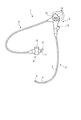
まず、実施の形態1における内視鏡装置について説明する。図1は、本実施の形態1における内視鏡装置の概略構成を示す図である。図1に示すように、本実施の形態1における内視鏡装置1は、細長な挿入部2と、この挿入部2の基端側であって内視鏡装置操作者が把持する操作部3と、この操作部3の側部より延伸する可撓性のユニバーサルコード4とを備える。ユニバーサルコード4は、ライトガイドケーブルや電気系ケーブルなどを内蔵する。
(Embodiment 1)
First, the endoscope apparatus according to the first embodiment will be described. FIG. 1 is a diagram illustrating a schematic configuration of the endoscope apparatus according to the first embodiment. As shown in FIG. 1, an endoscope apparatus 1 according to the first embodiment includes an elongated insertion part 2 and an operation part 3 on the proximal end side of the insertion part 2 and held by an endoscope apparatus operator. And a flexible universal cord 4 extending from the side portion of the operation portion 3. The universal cord 4 includes a light guide cable, an electric cable, and the like.

挿入部2は、CCDなどの撮像素子を有する撮像モジュールを内蔵した先端部5と、複数の湾曲駒によって構成され湾曲自在の湾曲部6と、この湾曲部6の基端側に設けられた長尺であって可撓性を有する可撓管部7とを備える。   The insertion portion 2 includes a distal end portion 5 incorporating an imaging module having an imaging element such as a CCD, a bending portion 6 that is configured by a plurality of bending pieces, and a length provided on the proximal end side of the bending portion 6. And a flexible tube portion 7 having flexibility.

ユニバーサルコード4の延伸側端部にはコネクタ部8が設けられており、コネクタ部8には、光源装置に着脱自在に接続されるライトガイドコネクタ9、CCDなどで光電変換した被写体像の電気信号を信号処理装置や制御装置に伝送するための電気接点部10、先端部5のノズルに空気を送るための送気口金11などが設けられている。なお、光源装置は、ハロゲンランプなどが内蔵されたものであり、ハロゲンランプからの光を、ライトガイドコネクタ9を介して接続された内視鏡装置1へ照明光として供給する。また、信号処理装置や制御装置は、撮像素子に電源を供給し、撮像素子から光電変換された電気信号が入力される装置であり、撮像素子によって撮像された電気信号を処理して接続する表示装置に画像を表示させるとともに、撮像素子のゲイン調整などの制御および駆動を行なう駆動信号の出力を行なう。   A connector portion 8 is provided at the end of the universal cord 4 on the extending side. The connector portion 8 has a light guide connector 9 that is detachably connected to the light source device, an electrical signal of a subject image photoelectrically converted by a CCD or the like. Are provided with an electric contact portion 10 for transmitting the air to the signal processing device and the control device, an air supply base 11 for sending air to the nozzle of the tip portion 5, and the like. The light source device includes a halogen lamp or the like, and supplies light from the halogen lamp as illumination light to the endoscope device 1 connected via the light guide connector 9. The signal processing device or the control device is a device that supplies power to the image sensor and receives an electrical signal photoelectrically converted from the image sensor, and displays a display that processes and connects the electrical signal captured by the image sensor An image is displayed on the apparatus, and a drive signal for controlling and driving gain adjustment of the image sensor is output.

操作部3には湾曲部6を上下方向および左右方向に湾曲させる湾曲ノブ12、体腔内に生検鉗子、レーザプローブ等の処置具を挿入する処置具挿入部13、信号処理装置や制御装置あるいは送気、送水、送ガス手段などの周辺機器の操作を行なう複数のスイッチ14が設けられている。処置具挿入口に処置具が挿入された内視鏡装置1は、内部に設けられた処置具挿通用チャンネルを経て処置具の先端処置部を突出させ、たとえば生検鉗子によって患部組織を採取する生検などを行なう。   The operation unit 3 includes a bending knob 12 for bending the bending unit 6 in the vertical direction and the horizontal direction, a treatment tool insertion unit 13 for inserting a treatment tool such as a biopsy forceps and a laser probe into the body cavity, a signal processing device or a control device, A plurality of switches 14 for operating peripheral devices such as air supply, water supply, and gas supply means are provided. The endoscope apparatus 1 in which the treatment tool is inserted into the treatment tool insertion port projects the distal treatment portion of the treatment tool through the treatment tool insertion channel provided therein, and collects the affected tissue using, for example, biopsy forceps Perform biopsy.

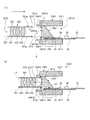
つぎに、内視鏡装置1の先端部5に搭載される撮像モジュールの構成について説明する。図2は、図1に示す内視鏡装置1の先端部5に搭載される撮像モジュールの分解斜視図であり、図3は、図2に示す撮像モジュールの断面図であり、撮像モジュールを構成する撮像素子の受光領域表面に対して鉛直な面で切断した場合の断面図である。   Next, the configuration of the imaging module mounted on the distal end portion 5 of the endoscope apparatus 1 will be described. 2 is an exploded perspective view of the imaging module mounted on the distal end portion 5 of the endoscope apparatus 1 shown in FIG. 1, and FIG. 3 is a cross-sectional view of the imaging module shown in FIG. It is sectional drawing at the time of cut | disconnecting in a surface perpendicular | vertical with respect to the light-receiving region surface of the image pick-up element to perform.

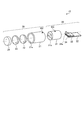
図2および図3に示すように、図1に示す内視鏡装置1の先端部5に搭載される撮像モジュール15は、複数の対物レンズを有するレンズユニット20と、撮像素子33を有する撮像ユニット30とによって構成される。   As shown in FIGS. 2 and 3, the imaging module 15 mounted on the distal end portion 5 of the endoscope apparatus 1 shown in FIG. 1 includes an imaging unit having a lens unit 20 having a plurality of objective lenses and an imaging element 33. 30.

レンズユニット20は、遮光材料で形成された両端が開口した中空円筒形のレンズホルダ21と、外部からの光を集光するレンズ22,23と、外部からの光を透過させる観察窓24とによって構成される。   The lens unit 20 includes a hollow cylindrical lens holder 21 formed of a light-shielding material and open at both ends, lenses 22 and 23 that collect light from the outside, and an observation window 24 that transmits light from the outside. Composed.

レンズホルダ21の開口サイズは、レンズ22,23および観察窓24の外周と合致する大きさであり、図3(1)および図3(2)に示すように、レンズ22,23および観察窓24は、それぞれの中心が同一軸上に位置するように、レンズホルダ21内部に組みつけられる。レンズホルダ21の各光学部材の組み付け時には、レンズホルダ21の外径中心軸と、レンズ22,23および観察窓24の中心、すなわちレンズ22,23および観察窓24によって構成されるレンズユニット20の光軸中心とは一致するように、各光学部材およびレンズホルダ21の形状が設計されている。なお、レンズホルダ21は、たとえば耐食鋼で形成されており、少なくとも外側は遮光されている。   The opening size of the lens holder 21 is a size that matches the outer periphery of the lenses 22 and 23 and the observation window 24. As shown in FIGS. 3 (1) and 3 (2), the lenses 22 and 23 and the observation window 24 are provided. Are assembled in the lens holder 21 so that their centers are located on the same axis. At the time of assembling each optical member of the lens holder 21, the light of the lens unit 20 constituted by the outer diameter central axis of the lens holder 21 and the centers of the lenses 22, 23 and the observation window 24, that is, the lenses 22, 23 and the observation window 24. The shape of each optical member and the lens holder 21 is designed so as to coincide with the axis center. The lens holder 21 is made of, for example, corrosion resistant steel, and at least the outer side is shielded from light.

レンズホルダ21端部の開口部21aから観察窓24を介してレンズホルダ21内部に入射した外部からの光は、レンズ22,23によって集光される。そして、レンズ22,23によって集光された集光光は、レンズホルダ21他端の開口部21bから出射する。レンズホルダ21の開口部21b側の出射側端部の厚さは、周方向のいずれもほぼ均一な厚さである。   Light from the outside incident on the inside of the lens holder 21 through the observation window 24 from the opening 21 a at the end of the lens holder 21 is collected by the lenses 22 and 23. The condensed light collected by the lenses 22 and 23 is emitted from the opening 21 b at the other end of the lens holder 21. The thickness of the exit end on the opening 21b side of the lens holder 21 is substantially uniform in the circumferential direction.

撮像ユニット30は、両端が開口した中空の円柱形の撮像ホルダ31と、基板32上に実装された撮像素子33と、撮像素子33上に載置されるプリズム34とによって構成される。撮像ホルダ31は、たとえば耐食鋼で形成される。   The imaging unit 30 includes a hollow cylindrical imaging holder 31 having both ends opened, an imaging element 33 mounted on a substrate 32, and a prism 34 placed on the imaging element 33. The imaging holder 31 is made of, for example, corrosion resistant steel.

撮像素子33は、CCDまたはCMOSイメージセンサ等に例示されるベアチップ状の半導体素子であり、被写体からの光を受光して被写体の画像を撮像する撮像機能を有する。図3に示すように、撮像素子33には、チップ基板の上面に、被写体からの光を受光し、この受光した光を光電変換処理する受光領域33aが形成されている。撮像モジュール15完成時にレンズユニット20の光軸と受光領域33a面とは略平行となるように撮像素子33は配置される。   The imaging element 33 is a bare chip-shaped semiconductor element exemplified by a CCD or CMOS image sensor, and has an imaging function of receiving light from a subject and capturing an image of the subject. As shown in FIG. 3, the image sensor 33 has a light receiving region 33a on the upper surface of the chip substrate for receiving light from the subject and performing photoelectric conversion processing on the received light. When the imaging module 15 is completed, the imaging element 33 is arranged so that the optical axis of the lens unit 20 and the surface of the light receiving region 33a are substantially parallel.

受光領域33aは、格子形状等の所定の形状に配置される画素群、および、光を効率よく集光するために画素群上に形成されるマイクロレンズ等を用いて実現される。受光領域33aの表面は長方形をなし、受光領域33aは撮像素子33のチップ基板上の所定位置に形成される。また、撮像素子33は、撮像動作を実行するための駆動回路が形成された駆動回路部(図示しない)と、外部接続用電極(図示しない)とを備える。   The light receiving region 33a is realized by using a pixel group arranged in a predetermined shape such as a lattice shape, a microlens formed on the pixel group in order to efficiently collect light. The surface of the light receiving region 33 a is rectangular, and the light receiving region 33 a is formed at a predetermined position on the chip substrate of the image sensor 33. The image sensor 33 includes a drive circuit unit (not shown) in which a drive circuit for executing an imaging operation is formed, and an external connection electrode (not shown).

撮像素子33は、外部接続用電極と基板32の外部接続用電極とがワイヤ35で接続されることによって基板32上に実装される。このとき、撮像素子33は、受光領域33aが形成された面を上面として基板32上に実装される。受光領域33aは、受光した光を光電変換処理し、駆動回路部は、受光領域33aにおいて光電変換処理された信号をもとに被写体の画像信号を生成し、この生成した画像信号を、外部接続用電極を介して基板32に出力する。基板32に出力された画像信号は、基板32に接続された配線ケーブル37によって画像信号が信号処理装置や制御装置に伝送される。なお、基板32には、信号制御用の部品36が実装される場合もある。   The imaging element 33 is mounted on the substrate 32 by connecting the external connection electrode and the external connection electrode of the substrate 32 with a wire 35. At this time, the image sensor 33 is mounted on the substrate 32 with the surface on which the light receiving region 33a is formed as an upper surface. The light receiving region 33a performs photoelectric conversion processing on the received light, and the drive circuit unit generates an image signal of the subject based on the signal subjected to photoelectric conversion processing in the light receiving region 33a, and the generated image signal is connected to the external connection. And output to the substrate 32 through the electrode for use. The image signal output to the substrate 32 is transmitted to the signal processing device and the control device by the wiring cable 37 connected to the substrate 32. Note that a signal control component 36 may be mounted on the substrate 32.

プリズム34は、撮像素子33の受光領域33a上に載置され、外部からの光を屈折させる。プリズム34によって屈折された光は、撮像素子33の受光領域33aで受光される。プリズム34の底面には、受光領域33aのマイクロレンズの直上にエアギャップを形成するための凹部(図示しない)が形成される。プリズム34は、光入射面34aが台形である角柱形状である。そして、図3(2)に示すように、プリズム34は、プリズム34の光入射面34aの点C2で示す位置を通った光が、プリズム34の屈折面で屈折後に撮像素子33の受光領域33aの中心C1に到達するように撮像素子33上に実装されている。この点C2は、プリズム34の光入射面34aのうち、受光領域33aで受光される光が入射する領域である基準領域の中心に該当する。   The prism 34 is placed on the light receiving region 33a of the image sensor 33 and refracts light from the outside. The light refracted by the prism 34 is received by the light receiving region 33 a of the image sensor 33. A concave portion (not shown) for forming an air gap is formed on the bottom surface of the prism 34 immediately above the microlens in the light receiving region 33a. The prism 34 has a prismatic shape in which the light incident surface 34a is a trapezoid. Then, as shown in FIG. 3B, in the prism 34, the light passing through the position indicated by the point C2 on the light incident surface 34a of the prism 34 is refracted by the refractive surface of the prism 34, and then the light receiving region 33a of the image sensor 33. It is mounted on the image sensor 33 so as to reach the center C1. This point C2 corresponds to the center of the reference area that is the area where the light received by the light receiving area 33a is incident on the light incident surface 34a of the prism 34.

撮像ホルダ31は、円柱から底面が台形である角柱をくり抜いた中空形状である。そして、開口部31a,31bの大きさは、基板32、撮像素子33およびプリズム34がそれぞれ実装された状態で、開口部31bから撮像ホルダ31内部に組み付け可能なように設定されている。たとえば、開口部31a,31bの高さ方向の大きさは、基板32の基板厚さ、撮像素子33の基板厚さおよびプリズム34の光入射面高さの和とほぼ合致し、開口部31a,31bの幅方向の大きさは、基板32の短辺方向の大きさよりも大きい。基板32、撮像素子33およびプリズム34は、それぞれ実装された状態で撮像ホルダ31内に組み付けられる。   The imaging holder 31 has a hollow shape obtained by hollowing out a prism having a trapezoidal bottom surface from a cylinder. The sizes of the openings 31a and 31b are set so that the openings 32a and 31b can be assembled into the image pickup holder 31 from the openings 31b in a state where the substrate 32, the image pickup device 33, and the prism 34 are mounted. For example, the size of the openings 31a and 31b in the height direction substantially matches the sum of the substrate thickness of the substrate 32, the substrate thickness of the image sensor 33, and the light incident surface height of the prism 34. The size in the width direction of 31 b is larger than the size in the short side direction of the substrate 32. The substrate 32, the imaging element 33, and the prism 34 are assembled in the imaging holder 31 in a mounted state.

このとき、プリズム34の光入射面34aの外周面の一部が撮像ホルダ31の内周面に固定されることによって、撮像ホルダ31内部に基板32、撮像素子33およびプリズム34が組みつけられる。なお、撮像ホルダ31の各光学部材の組み付け時には、撮像ホルダ31の外径中心軸上にプリズム34の光入射面34aの基準領域の中心である点C2が位置するように、各光学部材および撮像ホルダ31の形状が設計されていてもよい。   At this time, a part of the outer peripheral surface of the light incident surface 34 a of the prism 34 is fixed to the inner peripheral surface of the imaging holder 31, whereby the substrate 32, the imaging element 33, and the prism 34 are assembled inside the imaging holder 31. Note that when assembling each optical member of the imaging holder 31, each optical member and the imaging are arranged such that the point C <b> 2 that is the center of the reference region of the light incident surface 34 a of the prism 34 is positioned on the outer diameter central axis of the imaging holder 31. The shape of the holder 31 may be designed.

ここで、レンズホルダ21の光出射側端部の内径と、撮像ホルダ31の光入射側端部の外径とは一致するように設定されている。すなわち、レンズホルダ21の開口部21bの内径R21bと、撮像ホルダ31の開口部31aの外径R31aとは、同径である。   Here, the inner diameter of the light emitting side end of the lens holder 21 and the outer diameter of the light incident side end of the imaging holder 31 are set to coincide with each other. That is, the inner diameter R21b of the opening 21b of the lens holder 21 and the outer diameter R31a of the opening 31a of the imaging holder 31 are the same diameter.

このため、図3(1)の矢印のように、レンズホルダ21の開口部21bを介して、レンズホルダ21内部に撮像ホルダ31の光入射側端部が差し込まれることによって、レンズホルダ21の光出射側端部と撮像ホルダ31の光入射側端部とは、図3(2)のように、直接、嵌合可能である。   For this reason, the light incident side end of the imaging holder 31 is inserted into the lens holder 21 through the opening 21b of the lens holder 21 as indicated by the arrow in FIG. The exit side end and the light incident side end of the imaging holder 31 can be directly fitted as shown in FIG.

前述したように、レンズホルダ21の外径中心軸とレンズユニット20の光軸中心とは一致しており、撮像ホルダ31の外径中心軸上にプリズム34の光入射面34aの基準領域の中心である点C2が位置するため、レンズホルダ21に撮像ホルダ31を差し込んだ場合には、レンズ22の中心C3を通るレンズユニット20の光軸中心と、プリズム34の光入射面34aの基準領域の中心である点C2とが同一の軸L1上に位置することとなる。   As described above, the outer diameter central axis of the lens holder 21 and the optical axis center of the lens unit 20 coincide with each other, and the center of the reference region of the light incident surface 34a of the prism 34 on the outer diameter central axis of the imaging holder 31 is obtained. When the imaging holder 31 is inserted into the lens holder 21, the center of the optical axis of the lens unit 20 passing through the center C3 of the lens 22 and the reference region of the light incident surface 34a of the prism 34 are located. The center point C2 is located on the same axis L1.

このように、レンズホルダ21および撮像ホルダ31は、レンズユニット20の各構成部材の大きさ、撮像ホルダ31の各構成部材の大きさおよび各光学系の光軸などをもとに、レンズホルダ21の光出射側端部と撮像ホルダ31の光入射側端部との嵌合時には、レンズホルダ21に組み付けられたレンズ22,23の光軸中心が、撮像ホルダ31内部に固定されるプリズム34の基準領域の中心である点C2を通るように、形状が設計されている。また、プリズム34の光入射面の外周面の一部は撮像ホルダ31の内周面に固定されるため、レンズホルダ21の光出射側端部の内周面21cは、レンズユニット20の光軸中心と、プリズム34の光入射面34aの基準領域の中心である点C2とが同一の軸L1上に位置するように、撮像ホルダ31の外周面31cによって位置規定される。   As described above, the lens holder 21 and the imaging holder 31 are based on the size of each constituent member of the lens unit 20, the size of each constituent member of the imaging holder 31, the optical axis of each optical system, and the like. The optical axis center of the lenses 22 and 23 assembled to the lens holder 21 is fixed to the inside of the imaging holder 31 when the light emission side end of the lens holder 21 and the light incident side end of the imaging holder 31 are fitted. The shape is designed to pass through the point C2, which is the center of the reference region. Further, since a part of the outer peripheral surface of the light incident surface of the prism 34 is fixed to the inner peripheral surface of the imaging holder 31, the inner peripheral surface 21 c of the light emitting side end portion of the lens holder 21 is the optical axis of the lens unit 20. The position is defined by the outer peripheral surface 31c of the imaging holder 31 so that the center and the point C2 that is the center of the reference region of the light incident surface 34a of the prism 34 are located on the same axis L1.

そして、プリズム34は、プリズム34の光入射面34aの基準領域の中心である点C2を通った光が受光領域33aの中心C1に到達するように撮像素子上に実装されている。このため、レンズホルダ21の各レンズ22,23による集光光は、光軸中心が撮像素子33の受光領域33aの中心と一致する状態で、プリズム34の光入射面34aに入射する。したがって、レンズホルダ21の光出射側端部と撮像ホルダ31の光入射側端部との嵌合時には、レンズユニット20の各レンズ22,23を含む光学部材の光軸中心と、撮像ユニット30の撮像素子33の受光領域33aで受光する光の中心とは一致することとなる。   The prism 34 is mounted on the image sensor so that the light passing through the point C2, which is the center of the reference area of the light incident surface 34a of the prism 34, reaches the center C1 of the light receiving area 33a. For this reason, the condensed light from the lenses 22 and 23 of the lens holder 21 is incident on the light incident surface 34 a of the prism 34 in a state where the center of the optical axis coincides with the center of the light receiving region 33 a of the image sensor 33. Accordingly, when the light emitting side end of the lens holder 21 and the light incident side end of the imaging holder 31 are fitted, the optical axis center of the optical member including the lenses 22 and 23 of the lens unit 20 and the imaging unit 30 The center of the light received by the light receiving region 33a of the image sensor 33 coincides.

さらに、図2に示すように、レンズホルダ21の外周面のうち集光光出射側端部には、三角形のマークM2が付されており、撮像ホルダ31の外周面31cのうち光入射側端部には、三角形のマークM3が付されている。このマークM2およびマークM3は、軸L1方向および各ホルダの周方向(軸L1を中心とした周方向)における各ホルダの位置を規定できるように付されたものである。   Further, as shown in FIG. 2, a triangular mark M <b> 2 is attached to the collected light emitting side end portion of the outer peripheral surface of the lens holder 21, and the light incident side end of the outer peripheral surface 31 c of the imaging holder 31. A triangle mark M3 is attached to the part. The marks M2 and M3 are attached so that the positions of the holders in the direction of the axis L1 and the circumferential direction of each holder (the circumferential direction around the axis L1) can be defined.

組み立て時には、まず、レンズホルダ21の出射側端部の内周面21c、あるいは、撮像ホルダ31の入射側端部の外周面31cの少なくも一方に接着剤を塗布する。次いで、上から見てレンズホルダ21のマークM2の頂点と撮像ホルダ31のマークM3の頂点とが同軸上となるように、レンズホルダ21に撮像ホルダ31を嵌め込む。そして、レンズホルダ21のマークM2の頂点に撮像ホルダ31のマークM3の頂点が到達するまで、レンズホルダ21内に撮像ホルダ31を差し込む。なお、接着剤の種類によっては接着剤硬化処理をさらに行う。   At the time of assembly, first, an adhesive is applied to at least one of the inner peripheral surface 21c of the exit side end portion of the lens holder 21 or the outer peripheral surface 31c of the incident side end portion of the imaging holder 31. Next, the imaging holder 31 is fitted into the lens holder 21 so that the vertex of the mark M2 of the lens holder 21 and the vertex of the mark M3 of the imaging holder 31 are coaxial with each other when viewed from above. Then, the imaging holder 31 is inserted into the lens holder 21 until the vertex of the mark M3 of the imaging holder 31 reaches the vertex of the mark M2 of the lens holder 21. Depending on the type of adhesive, an adhesive curing process is further performed.

このように、実施の形態1にかかる撮像モジュール15は、レンズ22の中心C3を通る各光学部材の光軸中心と、プリズム34の光入射面34aの中心である点C2とが一致するように、レンズホルダ21の集光光出射側端部が、撮像ホルダ31の外周面で位置規定される。言い換えると、撮像モジュール15は、レンズ22の中心C3を通る各光学部材の光軸中心と、撮像素子33の受光領域33aで受光する光の中心とが一致するように、レンズホルダ21の集光光出射側端部が、撮像ホルダ31の外周面で位置規定される。このため、レンズホルダ21の集光光出射側端部と撮像ホルダ31の集光光入射側端部とをただ嵌め合わせるという簡易な製造工程で、レンズユニット20の光学部材の光軸中心と撮像ユニット30の撮像素子33の受光領域33aで受光する光の中心とを一致させた撮像モジュールを製造することができる。   As described above, in the imaging module 15 according to the first embodiment, the optical axis center of each optical member that passes through the center C3 of the lens 22 and the point C2 that is the center of the light incident surface 34a of the prism 34 coincide with each other. The end of the condensed light exit side of the lens holder 21 is defined by the outer peripheral surface of the imaging holder 31. In other words, the imaging module 15 condenses the lens holder 21 so that the optical axis center of each optical member passing through the center C3 of the lens 22 and the center of the light received by the light receiving region 33a of the imaging element 33 coincide. The position of the light emitting side end is defined by the outer peripheral surface of the imaging holder 31. For this reason, the optical axis center of the optical member of the lens unit 20 and the imaging can be obtained by a simple manufacturing process in which the collected light emitting side end of the lens holder 21 and the collected light incident side end of the imaging holder 31 are simply fitted together. An imaging module in which the center of the light received by the light receiving region 33a of the imaging element 33 of the unit 30 is matched can be manufactured.

また、撮像モジュール15においては、レンズホルダ21の外周に付したマークM2と撮像ホルダ31の外周に付したマークM3とが合うようにレンズホルダ21の集光光出射側端部と撮像ホルダ31の集光光入射側端部とを嵌め合わせるだけで、各ホルダの軸L1方向の位置および各ホルダの軸L1を中心とした周方向の位置を正確に規定することができる。   In the imaging module 15, the condensing light emitting side end of the lens holder 21 and the imaging holder 31 are aligned so that the mark M 2 attached to the outer periphery of the lens holder 21 and the mark M 3 attached to the outer periphery of the imaging holder 31 are aligned. By simply fitting the collected light incident side end portion, the position in the direction of the axis L1 of each holder and the position in the circumferential direction around the axis L1 of each holder can be accurately defined.

また、撮像モジュール15は、レンズホルダ21の集光光出射側端部と撮像ホルダ31の集光光入射側端部とを他の部材を介さずに直接嵌合可能であるため、内視鏡装置の挿入具先端部の細径化を図ることができるとともに、部材介在による光量の損失も低減でき良好な画像を取得できる。   In addition, the imaging module 15 can directly fit the collected light emitting side end of the lens holder 21 and the collected light incident side end of the imaging holder 31 without using any other member. The diameter of the distal end portion of the insertion tool of the apparatus can be reduced, and the loss of light quantity due to the intervention of the members can be reduced, so that a good image can be acquired.

(実施の形態2)
次に、実施の形態2について説明する。実施の形態2においては、レンズホルダを撮像ホルダに差し込むことによって組み立てる撮像モジュールについて説明する。
(Embodiment 2)
Next, a second embodiment will be described. In the second embodiment, an imaging module assembled by inserting a lens holder into an imaging holder will be described.

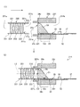
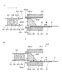
図4は、実施の形態2にかかる撮像モジュールの分解斜視図であり、図5は、図4に示す撮像モジュールの断面図であり、撮像モジュールを構成する撮像素子の受光領域表面に対して鉛直な面で切断した場合の断面図である。図4および図5に示すように、実施の形態2にかかる撮像モジュール215は、レンズユニット220と、撮像素子33を有する撮像ユニット230とによって構成される。   FIG. 4 is an exploded perspective view of the imaging module according to the second embodiment, and FIG. 5 is a cross-sectional view of the imaging module shown in FIG. 4, and is perpendicular to the surface of the light receiving region of the imaging device that constitutes the imaging module. It is sectional drawing at the time of cut | disconnecting in a smooth surface. As shown in FIGS. 4 and 5, the imaging module 215 according to the second embodiment includes a lens unit 220 and an imaging unit 230 having an imaging element 33.

レンズユニット220は、両端が開口した中空の円柱形のレンズホルダ221と、外部からの光を集光するレンズ222,223と、外部からの光を透過させる観察窓224とによって構成される。   The lens unit 220 includes a hollow cylindrical lens holder 221 that is open at both ends, lenses 222 and 223 that collect light from the outside, and an observation window 224 that transmits light from the outside.

レンズホルダ221の開口部221aは、レンズ222,223および観察窓224の外周と合致する大きさの円形であり、図5(1)および図5(2)に示すように、レンズ222,223および観察窓224は、それぞれの中心がレンズホルダ221の外径中心軸と同軸上に位置するようにレンズホルダ221内部に組みつけられる。レンズホルダ221端部の開口部221aから観察窓224を介してレンズホルダ221内部に入射した外部からの光は、レンズ222,223によって集光され、この集光光は、レンズホルダ221他端の開口部221bから出射する。レンズホルダ221の開口部221bのうち少なくともプリズム34の外周面と接触する部分(図5(1)に示す端部部分231j)は、プリズム34の光入射面34aと同形の台形の開口形状となっている。なお、レンズホルダ221は、たとえば耐食鋼で形成されており、少なくとも外側は遮光されている。   The opening 221a of the lens holder 221 has a circular shape that matches the outer circumference of the lenses 222, 223 and the observation window 224. As shown in FIGS. 5 (1) and 5 (2), the lenses 222, 223 and The observation window 224 is assembled inside the lens holder 221 so that the center of each of the observation windows 224 is positioned coaxially with the outer diameter central axis of the lens holder 221. Light from the outside that enters the lens holder 221 through the observation window 224 from the opening 221a at the end of the lens holder 221 is collected by the lenses 222 and 223, and this condensed light is collected at the other end of the lens holder 221. The light is emitted from the opening 221b. Of the opening 221 b of the lens holder 221, at least a portion (end portion 231 j shown in FIG. 5A) that contacts the outer peripheral surface of the prism 34 has a trapezoidal opening shape that is the same shape as the light incident surface 34 a of the prism 34. ing. The lens holder 221 is made of, for example, corrosion resistant steel, and at least the outer side is shielded from light.

撮像ユニット230は、両端が開口した中空の撮像ホルダ231と、基板32上に実装された撮像素子33と、撮像素子33上に載置されるプリズム34とによって構成される。撮像ホルダ231は、たとえば耐食鋼で形成される。   The imaging unit 230 includes a hollow imaging holder 231 having both ends opened, an imaging element 33 mounted on the substrate 32, and a prism 34 placed on the imaging element 33. The imaging holder 231 is made of, for example, corrosion resistant steel.

撮像ホルダ231は、角柱の一側面から円柱が突出した形状を有する。撮像ホルダ231の円柱部分は略中空円筒形を有し、角柱部分は底面が台形である角柱をくり抜いた中空形状を有する。   The imaging holder 231 has a shape in which a cylinder protrudes from one side of a prism. The columnar portion of the imaging holder 231 has a substantially hollow cylindrical shape, and the prism portion has a hollow shape obtained by hollowing out a prism having a trapezoidal bottom surface.

撮像ホルダ231の角柱部分の開口部231bの大きさは、基板32、撮像素子33およびプリズム34がそれぞれ実装された状態で、開口部231bを介して、撮像ホルダ231内部に組み付け可能なように設定される。基板32、撮像素子33およびプリズム34は、基板32の底面の一部が撮像ホルダ231の内周面に固定されることによって撮像ホルダ231内部に組みつけられる。たとえば、撮像ホルダ231の各光学部材の組み付け時には、撮像ホルダ231の外径中心軸上にプリズム34の光入射面34aの基準領域の中心である点C2が位置するように、各光学部材および撮像ホルダ231の形状が設計されている。なお、実施の形態1と同様に、図5(2)に示すように、プリズム34は、プリズム34の光入射面34aの点C2を通った光が、撮像素子33の受光領域33aの中心C1に到達するように撮像素子33上に実装されている。   The size of the opening 231b in the prismatic part of the imaging holder 231 is set so that it can be assembled into the imaging holder 231 via the opening 231b in a state where the substrate 32, the imaging device 33, and the prism 34 are mounted. Is done. The substrate 32, the imaging element 33, and the prism 34 are assembled inside the imaging holder 231 by fixing a part of the bottom surface of the substrate 32 to the inner peripheral surface of the imaging holder 231. For example, when the optical members of the imaging holder 231 are assembled, the optical members and the imaging are arranged so that the point C2 that is the center of the reference region of the light incident surface 34a of the prism 34 is positioned on the outer diameter central axis of the imaging holder 231. The shape of the holder 231 is designed. As in the first embodiment, as shown in FIG. 5B, in the prism 34, the light passing through the point C2 on the light incident surface 34a of the prism 34 is the center C1 of the light receiving region 33a of the image sensor 33. It is mounted on the image sensor 33 so as to reach.

そして、レンズユニット220から出射した集光光が入射する撮像ホルダ231の円柱部分の円形の開口部231aの内径は、レンズホルダ221の外径よりも大きい。このため、図5(1)の矢印のように、撮像ホルダ231の円柱部分の開口部231bを介して、撮像ホルダ231内部にレンズホルダ221の光出射側端部が嵌め込まれることによって、レンズホルダ221の光出射側端部と撮像ホルダ231の光入射側端部とは、図5(2)のように、直接、嵌合可能である。   The inner diameter of the circular opening 231 a of the cylindrical portion of the imaging holder 231 to which the condensed light emitted from the lens unit 220 is incident is larger than the outer diameter of the lens holder 221. For this reason, as shown by the arrow in FIG. 5A, the light emitting side end of the lens holder 221 is fitted into the imaging holder 231 through the opening 231 b of the cylindrical portion of the imaging holder 231. The light emission side end of 221 and the light incidence side end of the imaging holder 231 can be directly fitted as shown in FIG.

ここで、レンズホルダ221および撮像ホルダ231は、レンズホルダ221の光出射側端部と撮像ホルダ231の光入射側端部との嵌合時には、レンズ222の中心C32を通るレンズユニット220の光軸中心が、撮像ホルダ231内部に固定されるプリズム34の光入射面34aの点C2を通るように、形状が設計されている。さらに、レンズホルダ221の開口部221bの端部部分231jの開口形状と、撮像ホルダ231に組み付けられるプリズム34の光入射面34aの形状とは同形となるように形成されており、レンズホルダ221の内周面221cがプリズム34の外周面34cに直接嵌まることで、図5(2)の図中上下方向のレンズホルダ221の位置が規定される。すなわち、レンズホルダ221の光出射側端部と撮像ホルダ231の光入射側端部との嵌合時には、レンズ222の中心C32を通るレンズユニット220の光軸中心と、プリズム34の光入射面34aの点C2とが同一の軸L2上に位置するように、レンズホルダ221の光出射側端部の内周面221cが、プリズム34の外周面34cで直接位置規定される。プリズム34は光入射面34aの点C2を通った光が受光領域33aの中心C1に到達するように撮像素子33上に実装されているため、レンズユニット220の光学部材の光軸中心と、撮像ユニット230の撮像素子33の受光領域33aで受光する光の中心とは一致することとなる。なお、レンズホルダ221の光出射側端部の外周面の一部も、撮像ホルダ231の内周面の一部で位置規定される。   Here, when the lens holder 221 and the imaging holder 231 are fitted to the light emitting side end of the lens holder 221 and the light incident side end of the imaging holder 231, the optical axis of the lens unit 220 passing through the center C32 of the lens 222. The shape is designed so that the center passes through the point C2 of the light incident surface 34a of the prism 34 fixed inside the imaging holder 231. Further, the opening shape of the end portion 231j of the opening 221b of the lens holder 221 and the shape of the light incident surface 34a of the prism 34 assembled to the imaging holder 231 are formed to be the same shape. By directly fitting the inner peripheral surface 221c to the outer peripheral surface 34c of the prism 34, the position of the lens holder 221 in the vertical direction in the drawing of FIG. That is, when the light emitting side end of the lens holder 221 and the light incident side end of the imaging holder 231 are fitted, the center of the optical axis of the lens unit 220 passing through the center C32 of the lens 222 and the light incident surface 34a of the prism 34. The inner peripheral surface 221c of the light emitting side end portion of the lens holder 221 is directly positioned by the outer peripheral surface 34c of the prism 34 so that the point C2 is located on the same axis L2. Since the prism 34 is mounted on the image sensor 33 so that the light passing through the point C2 of the light incident surface 34a reaches the center C1 of the light receiving region 33a, the optical axis center of the optical member of the lens unit 220 and the imaging The center of the light received by the light receiving region 33a of the image sensor 33 of the unit 230 coincides with the center. Note that a part of the outer peripheral surface of the light emitting side end of the lens holder 221 is also defined by a part of the inner peripheral surface of the imaging holder 231.

そして、実施の形態1と同様に、図4のようにレンズホルダ221の集光光出射側端部外周面と、撮像ホルダ231の光入射側端部外周面とには、軸L2方向および各ホルダの周方向(軸L2を中心とした周方向)における各ホルダの位置規定用の三角形のマークM22および三角形のマークM32がそれぞれ付されている。   As in the first embodiment, as shown in FIG. 4, the condensed light exit side end outer peripheral surface of the lens holder 221 and the light incident side end outer peripheral surface of the imaging holder 231 are arranged in the direction of the axis L2 and each A triangular mark M22 and a triangular mark M32 for defining the position of each holder in the circumferential direction of the holder (circumferential direction about the axis L2) are respectively attached.

組み立て時には、まず、レンズホルダ221の出射側端部の内周面221cに接着剤を塗布する。次いで、上から見てレンズホルダ221のマークM22の頂点と撮像ホルダ231のマークM32の頂点とが同軸上となるように、撮像ホルダ231にレンズホルダ221を嵌め込む。そして、撮像ホルダ231のマークM32の頂点にレンズホルダ221のマークM22の頂点が到達するまで、レンズホルダ221へ撮像ホルダ231を差し込む。なお、接着剤の種類によっては接着剤硬化処理をさらに行う。   At the time of assembly, first, an adhesive is applied to the inner peripheral surface 221c of the emission side end of the lens holder 221. Next, the lens holder 221 is fitted into the imaging holder 231 so that the vertex of the mark M22 of the lens holder 221 and the vertex of the mark M32 of the imaging holder 231 are coaxial when viewed from above. Then, the imaging holder 231 is inserted into the lens holder 221 until the vertex of the mark M22 of the lens holder 221 reaches the vertex of the mark M32 of the imaging holder 231. Depending on the type of adhesive, an adhesive curing process is further performed.

このように、レンズホルダ221の光出射側端部をプリズム34の外周面34cで位置規定した場合も、マークM22とマークM32とが合うようにレンズホルダ221の集光光出射側端部と撮像ホルダ231の集光光入射側端部とをただ嵌め合わせるだけで、レンズユニット220の光学部材の光軸中心と、撮像ユニット230の撮像素子33の受光領域33aで受光する光の中心とを一致させ、さらに各ホルダの軸L2方向および軸L2を中心とした周方向の位置を正確に規定させることができる。   As described above, even when the position of the light emitting side end of the lens holder 221 is defined by the outer peripheral surface 34c of the prism 34, imaging is performed with the condensed light emitting side end of the lens holder 221 so that the mark M22 and the mark M32 are aligned. The optical axis center of the optical member of the lens unit 220 and the center of the light received by the light receiving region 33a of the image pickup device 33 of the image pickup unit 230 are matched by simply fitting the collected light incident side end of the holder 231 together. Further, the position of each holder in the axis L2 direction and the circumferential direction around the axis L2 can be accurately defined.

(実施の形態3)
次に、実施の形態3について説明する。実施の形態3においては、プリズムの光入射面に形成された円柱状の突起部によって、レンズホルダの集光光出射側端部の位置を規定する場合について説明する。
(Embodiment 3)
Next, Embodiment 3 will be described. In the third embodiment, a case will be described in which the position of the condensed light emission side end portion of the lens holder is defined by a cylindrical projection formed on the light incident surface of the prism.

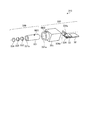
図6は、実施の形態3にかかる撮像モジュールの分解斜視図であり、図7は、図6に示す撮像モジュールの断面図であり、撮像モジュールを構成する撮像素子の受光領域表面に対して鉛直な面で切断した場合の断面図である。図6および図7に示すように、実施の形態3にかかる撮像モジュール315は、レンズユニット320と、撮像素子33を有する撮像ユニット330とによって構成される。   FIG. 6 is an exploded perspective view of the imaging module according to the third embodiment, and FIG. 7 is a cross-sectional view of the imaging module shown in FIG. 6, which is perpendicular to the light receiving region surface of the imaging device that constitutes the imaging module. It is sectional drawing at the time of cut | disconnecting in a smooth surface. As shown in FIGS. 6 and 7, the imaging module 315 according to the third embodiment includes a lens unit 320 and an imaging unit 330 having an imaging element 33.

レンズユニット320は、両端が開口した中空円筒形のレンズホルダ321と、外部からの光を集光するレンズ222,223と、外部からの光を透過させる観察窓224とによって構成される。レンズホルダ321の開口サイズは、レンズ222,223および観察窓224の外周と合致する大きさであり、図7(1)および図7(2)に示すように、レンズ222,223および観察窓224は、それぞれの中心がレンズホルダ321の外径中心軸と同軸上に位置するように、レンズホルダ321内部に組みつけられる。レンズホルダ321端部の開口部321aから観察窓224を介してレンズホルダ321内部に入射した外部からの光は、レンズ222,223によって集光され、この集光光は、レンズホルダ321他端の開口部321bから出射する。なお、レンズホルダ321は、たとえば耐食鋼で形成されており、少なくとも外側は遮光されている。   The lens unit 320 includes a hollow cylindrical lens holder 321 having both ends opened, lenses 222 and 223 that collect external light, and an observation window 224 that transmits external light. The opening size of the lens holder 321 is a size that matches the outer periphery of the lenses 222 and 223 and the observation window 224. As shown in FIGS. 7 (1) and 7 (2), the lenses 222 and 223 and the observation window 224 are arranged. Are assembled in the lens holder 321 so that their centers are located coaxially with the outer diameter central axis of the lens holder 321. Light from the outside that enters the lens holder 321 through the observation window 224 from the opening 321a at the end of the lens holder 321 is condensed by the lenses 222 and 223, and this condensed light is collected at the other end of the lens holder 321. The light is emitted from the opening 321b. The lens holder 321 is made of, for example, corrosion resistant steel, and at least the outer side is shielded from light.

撮像ユニット330は、両端が開口した中空の撮像ホルダ331と、基板32上に実装された撮像素子33と、撮像素子33上に載置されるプリズム334とによって構成される。撮像ホルダ331は、たとえば耐食鋼で形成される。   The imaging unit 330 includes a hollow imaging holder 331 that is open at both ends, an imaging element 33 that is mounted on the substrate 32, and a prism 334 that is placed on the imaging element 33. The imaging holder 331 is made of, for example, corrosion resistant steel.

プリズム334は、三角柱の一側面である光入射面334aに、円柱状の突起部334eが形成された形状を有する。この突起部334eの外径は、レンズホルダ321の開口部321b側の集光光出射側端部の内径と一致するように設定されている。   The prism 334 has a shape in which a cylindrical protrusion 334e is formed on a light incident surface 334a that is one side surface of a triangular prism. The outer diameter of the protrusion 334e is set to coincide with the inner diameter of the collected light exit end on the opening 321b side of the lens holder 321.

撮像ホルダ331は、撮像ホルダ231と同様に、角柱の一側面から円柱が突出した形状を有し、円柱部分は略中空円筒形を有し、角柱部分は底面が台形である角柱をくり抜いた中空形状を有する。   Similar to the imaging holder 231, the imaging holder 331 has a shape in which a cylinder protrudes from one side surface of a prism, the column part has a substantially hollow cylindrical shape, and the prism part has a hollow hollowed out a prism having a trapezoidal bottom surface. Has a shape.

撮像ホルダ331の角柱部分の開口部331bの大きさは、基板32、撮像素子33およびプリズム334がそれぞれ実装された状態で、開口部331bを介して、撮像ホルダ331内部に組み付け可能なように設定される。基板32、撮像素子33およびプリズム334は、基板32の底面の一部が撮像ホルダ331の内周面に固定されることによって撮像ホルダ331内部に組みつけられる。たとえば、撮像ホルダ331の各光学部材の組み付け時には、撮像ホルダ331の外径中心軸上にプリズム334の点C23が位置するように、各光学部材および撮像ホルダ331の形状が設計されている。この点C23は、光入射面334aの突起部334eの面334fのうち、撮像素子33の受光領域33aで受光される光が入射する領域である基準領域の中心に該当する。なお、実施の形態1と同様に、プリズム334は、図7(2)に示すように、プリズム334の点C23を通った光が、撮像素子33の受光領域33aの中心C1に到達するように撮像素子33上に実装されている。   The size of the opening 331b in the prismatic portion of the imaging holder 331 is set so that it can be assembled inside the imaging holder 331 via the opening 331b in a state where the substrate 32, the imaging device 33, and the prism 334 are mounted. Is done. The substrate 32, the imaging element 33, and the prism 334 are assembled inside the imaging holder 331 by fixing a part of the bottom surface of the substrate 32 to the inner peripheral surface of the imaging holder 331. For example, when the optical members of the imaging holder 331 are assembled, the shapes of the optical members and the imaging holder 331 are designed so that the point C23 of the prism 334 is positioned on the outer diameter central axis of the imaging holder 331. This point C23 corresponds to the center of the reference region, which is the region where the light received by the light receiving region 33a of the image sensor 33 is incident, of the surface 334f of the protrusion 334e of the light incident surface 334a. As in the first embodiment, the prism 334 is configured so that the light passing through the point C23 of the prism 334 reaches the center C1 of the light receiving region 33a of the image sensor 33, as shown in FIG. It is mounted on the image sensor 33.

そして、レンズユニット320から出射した集光光が入射する撮像ホルダ331の円柱部分の円形の開口部331aの内径は、レンズホルダ321の外径よりも大きい。このため、図7(1)の矢印のように、撮像ホルダ331の円柱部分の開口部331aを介して、撮像ホルダ331内部にレンズホルダ321の光出射側端部が嵌め込まれることによって、レンズホルダ321の光出射側端部と撮像ホルダ331の光入射側端部とは、図7(2)のように、直接、嵌合可能である。   The inner diameter of the circular opening 331 a of the cylindrical portion of the imaging holder 331 to which the condensed light emitted from the lens unit 320 is incident is larger than the outer diameter of the lens holder 321. For this reason, as shown by the arrow in FIG. 7A, the light emitting side end of the lens holder 321 is fitted into the imaging holder 331 via the opening 331 a of the columnar portion of the imaging holder 331, whereby the lens holder The light emitting side end of 321 and the light incident side end of the imaging holder 331 can be directly fitted as shown in FIG.

ここで、レンズホルダ321および撮像ホルダ331は、レンズホルダ321の光出射側端部と撮像ホルダ331の光入射側端部との嵌合時には、レンズ222の中心C32を通るレンズユニット320の光軸中心が、撮像ホルダ321内部に固定されるプリズム334の点C23を通るように、形状が設計されている。さらに、レンズホルダ321の開口部321b内径と、プリズム334の光入射面334aの突起部324eの外径とは一致するように形成されており、レンズホルダ321の内周面321cがプリズム334の突起部324eの外周面334cに直接嵌まることで、図7(2)の図中上下方向のレンズホルダ321の位置が規定される。レンズホルダ321の光出射側端部と撮像ホルダ331の光入射側端部との嵌合時には、レンズ222の中心C32を通るレンズユニット320の光軸中心と、プリズム334の点C23とが同一の軸L3上に位置するように、レンズホルダ321の光出射側端部の内周面321cが、プリズム334の突起部334eの外周面334cで直接位置規定される。また、プリズム334は点C23を通った光が受光領域33aの中心C1に到達するように撮像素子33上に実装されているため、レンズホルダ321の光出射側端部と撮像ホルダ331の光入射側端部との嵌合時には、レンズユニット320の光学部材の光軸中心と、撮像ユニット330の撮像素子33の受光領域33aで受光する光の中心とは一致することとなる。なお、レンズホルダ321の光出射側端部の外周面の一部も、撮像ホルダ331の内周面の一部で位置規定される。   Here, when the lens holder 321 and the imaging holder 331 are fitted to the light emitting side end of the lens holder 321 and the light incident side end of the imaging holder 331, the optical axis of the lens unit 320 passing through the center C32 of the lens 222. The shape is designed so that the center passes through the point C23 of the prism 334 fixed inside the imaging holder 321. Further, the inner diameter 321 c of the lens holder 321 is formed so that the inner diameter of the opening 321 b of the lens holder 321 coincides with the outer diameter of the protrusion 324 e of the light incident surface 334 a of the prism 334. The position of the lens holder 321 in the vertical direction in the drawing of FIG. 7B is defined by directly fitting on the outer peripheral surface 334c of the portion 324e. When the light emitting side end of the lens holder 321 and the light incident side end of the imaging holder 331 are fitted, the center of the optical axis of the lens unit 320 passing through the center C32 of the lens 222 and the point C23 of the prism 334 are the same. The inner peripheral surface 321c at the light emitting side end of the lens holder 321 is directly positioned by the outer peripheral surface 334c of the projection 334e of the prism 334 so as to be positioned on the axis L3. Since the prism 334 is mounted on the image sensor 33 so that the light passing through the point C23 reaches the center C1 of the light receiving region 33a, the light emission side end of the lens holder 321 and the light incident on the image holder 331 are provided. At the time of fitting with the side end portion, the optical axis center of the optical member of the lens unit 320 and the center of the light received by the light receiving region 33a of the imaging element 33 of the imaging unit 330 coincide with each other. A part of the outer peripheral surface of the light emitting side end of the lens holder 321 is also defined by a part of the inner peripheral surface of the imaging holder 331.

そして、レンズホルダ321の集光光出射側端部は、先端321fがプリズム334の光入射面334aに当て付けられることによって軸L3方向の位置が規定される。さらに、実施の形態1と同様に、図6のようにレンズホルダ321の集光光出射側端部外周面と、撮像ホルダ331の光入射側端部外周面とには、軸L3方向および各ホルダの周方向(軸L3を中心とした周方向)における各ホルダの位置規定用の三角形のマークM23および三角形のマークM33がそれぞれ付されている。   The end of the condensed light exit side of the lens holder 321 is positioned in the direction of the axis L3 by the tip 321f being applied to the light incident surface 334a of the prism 334. Further, as in the first embodiment, as shown in FIG. 6, the condensed light exit side end outer peripheral surface of the lens holder 321 and the light incident side end outer peripheral surface of the imaging holder 331 are arranged in the direction of the axis L3 and A triangular mark M23 and a triangular mark M33 for defining the position of each holder in the circumferential direction of the holder (circumferential direction about the axis L3) are respectively attached.

組み立て時には、まず、レンズホルダ321の出射側端部の内周面321cに接着剤を塗布する。次いで、上から見てレンズホルダ321のマークM23の頂点と撮像ホルダ331のマークM33の頂点とが同軸上となるように、撮像ホルダ331にレンズホルダ321を嵌め込む。そして、レンズホルダ321の集光光出射側端部の先端321fがプリズム334の光入射面334aに当て付くまで、レンズホルダ321へ撮像ホルダ331を差し込む。なお、接着剤の種類によっては接着剤硬化処理をさらに行う。   At the time of assembly, first, an adhesive is applied to the inner peripheral surface 321c of the emission side end of the lens holder 321. Next, the lens holder 321 is fitted into the imaging holder 331 so that the vertex of the mark M23 of the lens holder 321 and the vertex of the mark M33 of the imaging holder 331 are coaxial with each other when viewed from above. Then, the imaging holder 331 is inserted into the lens holder 321 until the tip 321f of the end of the condensed light exit side of the lens holder 321 contacts the light incident surface 334a of the prism 334. Depending on the type of adhesive, an adhesive curing process is further performed.

このように、レンズホルダ321の光出射側端部をプリズム334の突起部334eの外周面334cで位置規定した場合も、マークM23とマークM33とが合うようにレンズホルダ321の集光光出射側端部と撮像ホルダ331の集光光入射側端部とを嵌め合わせて、レンズホルダ321の集光光出射側端部の先端321fがプリズム334の光入射面334aに当て付くまでレンズホルダ321を撮像ホルダ331に差し込むだけで、レンズユニット320の光学部材の光軸中心と撮像ユニット330の撮像素子33の受光領域33aで受光する光の中心とを一致させ、さらに各ホルダの軸L3方向および軸L3を中心とした周方向の位置を正確かつ簡易に規定させることができる。   Thus, even when the light emitting side end of the lens holder 321 is positioned on the outer peripheral surface 334c of the projection 334e of the prism 334, the condensed light emitting side of the lens holder 321 is aligned so that the mark M23 and the mark M33 are aligned. The lens holder 321 is held until the end portion 321f of the lens holder 321 is brought into contact with the light incident surface 334a of the prism 334 by fitting the end portion with the collected light incident side end portion of the imaging holder 331. Just by inserting it into the imaging holder 331, the optical axis center of the optical member of the lens unit 320 and the center of the light received by the light receiving region 33a of the imaging device 33 of the imaging unit 330 are made to coincide with each other. The position in the circumferential direction around L3 can be accurately and easily defined.

(実施の形態3の変形例)
次に、実施の形態3の変形例について説明する。実施の形態3の変形例においては、プリズムの光入射面に形成された枠状の突起部によって、レンズホルダの集光光出射側端部の位置を規定する場合について説明する。
(Modification of Embodiment 3)
Next, a modification of the third embodiment will be described. In the modification of the third embodiment, a case will be described in which the position of the condensing light emitting side end portion of the lens holder is defined by a frame-shaped protrusion formed on the light incident surface of the prism.

図8は、実施の形態3の変形例にかかる撮像モジュールの分解斜視図であり、図9は、図8に示す撮像モジュールの断面図であり、撮像モジュールを構成する撮像素子の受光領域表面に対して鉛直な面で切断した場合の断面図である。図8および図9に示すように、実施の形態3にかかる撮像モジュール3151は、レンズユニット320と、撮像素子33を有する撮像ユニット3301とによって構成される。   8 is an exploded perspective view of an imaging module according to a modification of the third embodiment. FIG. 9 is a cross-sectional view of the imaging module shown in FIG. It is sectional drawing at the time of cut | disconnecting with respect to a perpendicular | vertical surface. As shown in FIGS. 8 and 9, the imaging module 3151 according to the third embodiment includes a lens unit 320 and an imaging unit 3301 having an imaging element 33.

撮像ユニット3301は、両端が開口した中空の撮像ホルダ3311と、基板32上に実装された撮像素子33と、撮像素子33上に載置されるプリズム3341とによって構成される。撮像ホルダ3311は、たとえば耐食鋼で形成される。   The imaging unit 3301 includes a hollow imaging holder 3311 having both ends opened, an imaging element 33 mounted on the substrate 32, and a prism 3341 placed on the imaging element 33. The imaging holder 3311 is made of, for example, corrosion resistant steel.

プリズム3341は、光入射面3341aが台形である角柱形状を有し、この光入射面3341aに、レンズホルダ321の開口部321b側の集光光出射側端部の外径と一致する内径を有する枠状の突起部3241eが形成されている。プリズム3341は、集光光入射方向側から見た場合、プリズム3341の光入射面には、レンズホルダ321の開口部321b側の集光光出射側端部の外径と一致する径を有する円状の開口が形成されるように見える。   The prism 3341 has a prismatic shape in which the light incident surface 3341a has a trapezoidal shape, and the light incident surface 3341a has an inner diameter that matches the outer diameter of the collected light emitting side end on the opening 321b side of the lens holder 321. A frame-shaped protrusion 3241e is formed. When viewed from the light incident direction side, the prism 3341 has a circle on the light incident surface of the prism 3341 having a diameter that matches the outer diameter of the end of the condensed light exit side on the opening 321b side of the lens holder 321. It appears that a shaped opening is formed.

撮像ホルダ3311は、撮像ホルダ231と同様に、角柱の一側面から円柱が突出した形状を有し、円柱部分は略中空円筒形を有し、角柱部分は底面が台形である角柱をくり抜いた中空形状を有する。   Similar to the imaging holder 231, the imaging holder 3311 has a shape in which a cylinder protrudes from one side surface of a prism, the column part has a substantially hollow cylindrical shape, and the prism part has a hollow hollowed out a prism having a trapezoidal bottom surface. Has a shape.

撮像ホルダ3311の角柱部分の開口部3311bの大きさは、基板32、撮像素子33およびプリズム3341がそれぞれ実装された状態で、開口部3311bを介して、撮像ホルダ3311内部に組み付け可能なように設定される。基板32、撮像素子33およびプリズム3341は、基板32の底面の一部およびプリズム3341の光入射面3341aに対する外周面の一部が撮像ホルダ3311の内周面に固定されることによって撮像ホルダ3311内部に組みつけられる。たとえば、撮像ホルダ3311の各光学部材の組み付け時には、撮像ホルダ3311の外径中心軸上にプリズム3341の光入射面3341aの点C231が位置するように、各光学部材および撮像ホルダ3311の形状が設計されている。この点C231は、光入射面3341aのうち、撮像素子33の受光領域33aで受光される光が入射する領域である基準領域の中心に該当する。なお、実施の形態1と同様に、プリズム3341は、図9(2)に示すように、プリズム3341の光入射面3341aの中心C231を通った光が、撮像素子33の受光領域33aの中心C1に到達するように撮像素子33上に実装されている。   The size of the opening 3311b in the prism portion of the imaging holder 3311 is set so that it can be assembled inside the imaging holder 3311 through the opening 3311b in a state where the substrate 32, the imaging device 33, and the prism 3341 are mounted. Is done. The substrate 32, the image sensor 33, and the prism 3341 are fixed to the inner peripheral surface of the imaging holder 3311 by fixing a part of the bottom surface of the substrate 32 and a part of the outer peripheral surface of the prism 3341 to the light incident surface 3341 a. Can be assembled. For example, when the optical members of the imaging holder 3311 are assembled, the shapes of the optical members and the imaging holder 3311 are designed so that the point C231 of the light incident surface 3341a of the prism 3341 is positioned on the outer diameter central axis of the imaging holder 3311. Has been. This point C231 corresponds to the center of a reference area, which is an area where light received by the light receiving area 33a of the image sensor 33 is incident, of the light incident surface 3341a. As in the first embodiment, as shown in FIG. 9B, in the prism 3341, the light passing through the center C231 of the light incident surface 3341a of the prism 3341 is the center C1 of the light receiving region 33a of the image sensor 33. It is mounted on the image sensor 33 so as to reach.

そして、レンズユニット320から出射した集光光が入射する撮像ホルダ3311の円柱部分の開口部3311aの内径は、レンズホルダ321の外径よりも大きい。このため、図9(1)の矢印のように、撮像ホルダ3311の円柱部分の開口部3311aを介して、撮像ホルダ3311内部にレンズホルダ321の光出射側端部が嵌め込まれることによって、レンズホルダ321の光出射側端部と撮像ホルダ3311の光入射側端部とは、図9(2)のように、直接、嵌合可能である。   The inner diameter of the opening 3311 a of the cylindrical portion of the imaging holder 3311 on which the condensed light emitted from the lens unit 320 is incident is larger than the outer diameter of the lens holder 321. For this reason, as shown by the arrow in FIG. 9 (1), the light emitting side end of the lens holder 321 is fitted into the imaging holder 3311 through the opening 3311a of the cylindrical portion of the imaging holder 3311, whereby the lens holder The light emitting side end of 321 and the light incident side end of the imaging holder 3311 can be directly fitted as shown in FIG.

レンズホルダ321および撮像ホルダ3311は、レンズホルダ321の光出射側端部と撮像ホルダ3311の光入射側端部との嵌合時には、レンズ222の中心C32を通るレンズユニット320の光軸中心が、撮像ホルダ3311内部に固定されるプリズム3341の点C231を通るように、形状が設計されている。さらに、レンズホルダ321の開口部321bの外径と、プリズム3341の光入射面3341aの突起部3341eの内径とは一致するように形成されており、レンズホルダ321の外周面321gがプリズム3341の突起部3341eの内周面3341fに直接嵌まることで、図9(2)の図中上下方向のレンズホルダ321の位置が規定される。レンズホルダ321の光出射側端部と撮像ホルダ3311の光入射側端部との嵌合時には、レンズ222の中心C32を通るレンズユニット320の光軸中心と、プリズム3341の点C231とが同一の軸L4上に位置するように、レンズホルダ321の光出射側端部の外周面321gが、プリズム3341の突起部3341eの内周面3341fで直接位置規定される。プリズム3341は点C231を通った光が受光領域33aの中心C1に到達するように撮像素子33上に実装されているため、レンズホルダ321の光出射側端部と撮像ホルダ3311の光入射側端部との嵌合時には、レンズユニット320の光学部材の光軸中心と、撮像ユニット3301の撮像素子33の受光領域33aで受光する光の中心とは一致することとなる。   When the lens holder 321 and the imaging holder 3311 are fitted to the light emitting side end of the lens holder 321 and the light incident side end of the imaging holder 3311, the optical axis center of the lens unit 320 passing through the center C32 of the lens 222 is The shape is designed so as to pass through the point C231 of the prism 3341 fixed inside the imaging holder 3311. Further, the outer diameter of the opening 321 b of the lens holder 321 and the inner diameter of the protrusion 3341 e of the light incident surface 3341 a of the prism 3341 are formed so that the outer peripheral surface 321 g of the lens holder 321 is the protrusion of the prism 3341. By directly fitting on the inner peripheral surface 3341f of the portion 3341e, the position of the lens holder 321 in the vertical direction in FIG. 9B is defined. When the light emitting side end of the lens holder 321 and the light incident side end of the imaging holder 3311 are fitted, the center of the optical axis of the lens unit 320 passing through the center C32 of the lens 222 and the point C231 of the prism 3341 are the same. The outer peripheral surface 321g of the light emitting side end of the lens holder 321 is directly positioned by the inner peripheral surface 3341f of the protrusion 3341e of the prism 3341 so as to be positioned on the axis L4. Since the prism 3341 is mounted on the imaging element 33 so that the light passing through the point C231 reaches the center C1 of the light receiving region 33a, the light emitting side end of the lens holder 321 and the light incident side end of the imaging holder 3311 are mounted. At the time of fitting with the optical unit, the center of the optical axis of the optical member of the lens unit 320 and the center of the light received by the light receiving region 33a of the imaging element 33 of the imaging unit 3301 coincide.

そして、レンズホルダ321の集光光出射側端部は、先端321fがプリズム3341の光入射面3341aに当て付けられることによって軸L4方向の位置が規定される。なお、実施の形態1と同様に、図8のようにレンズホルダ321の集光光出射側端部外周面と、撮像ホルダ3311の光入射側端部外周面とには、各ホルダの軸L4を中心とした周方向における各ホルダの位置規定用の三角形のマークM231および三角形のマークM331がそれぞれ付されている。   Then, the position of the lens holder 321 in the direction of the axis L4 is defined by the end 321f of the lens holder 321 being brought into contact with the light incident surface 3341a of the prism 3341. As in the first embodiment, as shown in FIG. 8, the condensed light exit side end outer peripheral surface of the lens holder 321 and the light incident side end outer peripheral surface of the imaging holder 3311 are arranged on the axis L4 of each holder. A triangular mark M231 and a triangular mark M331 are provided for defining the position of each holder in the circumferential direction centered on.

組み立て時には、まず、レンズホルダ321の出射側端部の外周面321gに接着剤を塗布する。次いで、上から見てレンズホルダ321のマークM231の頂点と撮像ホルダ3311のマークM331の頂点とが同軸上となるように、撮像ホルダ3311にレンズホルダ321を嵌め込む。そして、レンズホルダ321の集光光出射側端部の先端321fがプリズム3341の光入射面3341aに当て付くまで、レンズホルダ321へ撮像ホルダ3311を差し込む。なお、接着剤の種類によっては接着剤硬化処理をさらに行う。   At the time of assembly, first, an adhesive is applied to the outer peripheral surface 321g of the exit side end of the lens holder 321. Next, the lens holder 321 is fitted into the imaging holder 3311 so that the vertex of the mark M231 of the lens holder 321 and the vertex of the mark M331 of the imaging holder 3311 are coaxial when viewed from above. Then, the imaging holder 3311 is inserted into the lens holder 321 until the tip 321f of the end of the condensed light exit side of the lens holder 321 contacts the light incident surface 3341a of the prism 3341. Depending on the type of adhesive, an adhesive curing process is further performed.

このように、レンズホルダ321の光出射側端部をプリズム3341の突起部3341eの内周面3341fで位置規定した場合も、撮像モジュール315と同様に、レンズホルダ321の集光光出射側端部の先端321fがプリズム3341の光入射面3341aに当て付くまでレンズホルダ321を撮像ホルダ3311に差し込むだけで撮像モジュール3151を簡易かつ正確に製造できる。   As described above, when the position of the light emitting side end of the lens holder 321 is defined by the inner peripheral surface 3341f of the protrusion 3341e of the prism 3341, the condensing light emitting side end of the lens holder 321 is the same as the imaging module 315. The imaging module 3151 can be manufactured simply and accurately by simply inserting the lens holder 321 into the imaging holder 3311 until the tip 321f of the lens 311 comes into contact with the light incident surface 3341a of the prism 3341.

なお、図10に示すプリズム3342のように、突起部3341eのさらに内周側に、さらに、レンズホルダ321の開口部321b側の集光光出射側端部の内径と一致する外径を有する円柱状の突起部3342eを形成して、レンズホルダ321の光出射側端部の外周面321gおよび内周面321cを、プリズム3342の突起部3341eの内周面および突起部3342eの外周面で位置規定してもよい。この場合、図10(1)の矢印のように、撮像ホルダ3311の光入射側端部内にレンズホルダ321の光出射側端部を嵌め込み、レンズホルダ321の集光光出射側端部の先端321fが、プリズム3342の突起部3341eと突起部3342eとの間の溝3342hの底に当て付くまでレンズホルダ321を撮像ホルダ3311に差し込むだけで、図10(2)に示す撮像モジュール3152を簡易かつ正確に製造できる。   In addition, like the prism 3342 shown in FIG. 10, a circle having an outer diameter that further matches the inner diameter of the end portion of the condensing light emission side on the opening 321 b side of the lens holder 321 further on the inner peripheral side of the protrusion 3341 e. A columnar protrusion 3342e is formed, and the outer peripheral surface 321g and the inner peripheral surface 321c of the light emitting side end of the lens holder 321 are defined by the inner peripheral surface of the protrusion 3341e and the outer peripheral surface of the protrusion 3342e of the prism 3342. May be. In this case, as shown by an arrow in FIG. 10A, the light emission side end of the lens holder 321 is fitted into the light incident side end of the imaging holder 3311, and the tip 321 f of the condensed light emission side end of the lens holder 321. However, the image pickup module 3152 shown in FIG. 10 (2) can be simply and accurately inserted by simply inserting the lens holder 321 into the image pickup holder 3311 until it touches the bottom of the groove 3342h between the protrusion 3341e and the protrusion 3342e of the prism 3342. Can be manufactured.

また、図11の撮像モジュール3153のように、レンズユニット320のレンズホルダ321の集光光出射側端部の先端321fを、撮像ユニット3303の撮像ホルダ3313に組み付けられたプリズム34の光入射面34aに直接接着させて、さらに撮像モジュールサイズを小型化させてもよい。また、図12の撮像モジュール3154のように、プリズム3344の光入射面3344aに対して、レンズホルダ321と同形状の中空円柱状の突起部3344iを一体的に形成し、この突起部3344i内部にレンズ222,223および観察窓224を組み込んでもよい。   Further, like the imaging module 3153 in FIG. 11, the light incident surface 34 a of the prism 34 assembled to the imaging holder 3313 of the imaging unit 3303 is connected to the tip 321 f of the condensed light emission side end of the lens holder 321 of the lens unit 320. The imaging module size may be further reduced by directly adhering to the substrate. Further, as in the imaging module 3154 of FIG. 12, a hollow cylindrical projection 3344i having the same shape as the lens holder 321 is integrally formed on the light incident surface 3344a of the prism 3344, and the projection 3344i is formed inside the projection 3344i. Lenses 222 and 223 and an observation window 224 may be incorporated.

また、本実施の形態1〜3においては、撮像素子33上に載置する光学部材として、プリズム34,334,3341,3342,3344を例に説明したが、もちろんこれに限らない。たとえば、図13に示す撮像モジュール415のように、撮像素子433に対しレンズホルダ21から出射された集光光を透過させる板状ガラス434を用いてもよい。   In the first to third embodiments, the prisms 34, 334, 3341, 3342, and 3344 have been described as examples of the optical member placed on the image sensor 33. However, the present invention is not limited to this. For example, as in the imaging module 415 illustrated in FIG. 13, a plate glass 434 that transmits the condensed light emitted from the lens holder 21 to the imaging element 433 may be used.

この場合、撮像素子433が実装された基板432は、撮像モジュール415完成時にはレンズユニット20の光軸と受光領域433a面とが直交するように撮像ユニット430の撮像ホルダ431内部に組み付けられる。そして、板状ガラス434は、板状ガラス434の光入射面434aの中心C2´と撮像素子433の受光領域433aの中心C1´とが同一軸上に位置するように、撮像素子433上に実装される。この中心C2´は、板状ガラス434の光入射面434aのうち、受光領域433aで受光される光が入射する領域である基準領域の中心に該当する。また、板状ガラス434は、略円柱状であり、板状ガラス434の外径は、レンズホルダ21の光出射側端部の内径と一致する。このため、レンズホルダ21の内周面が板状ガラス434の外周面434jに嵌まることで、レンズ22の中心C3を通るレンズユニット20の光軸中心と、板状ガラス434の中心C2´と撮像素子433の受光領域433aの中心C1´とが同一軸上に位置するようにレンズホルダ21が位置決めされる。   In this case, when the imaging module 415 is completed, the substrate 432 on which the imaging element 433 is mounted is assembled inside the imaging holder 431 of the imaging unit 430 so that the optical axis of the lens unit 20 and the surface of the light receiving region 433a are orthogonal to each other. The plate glass 434 is mounted on the image sensor 433 so that the center C2 ′ of the light incident surface 434a of the plate glass 434 and the center C1 ′ of the light receiving region 433a of the image sensor 433 are located on the same axis. Is done. The center C2 ′ corresponds to the center of the reference region, which is a region where light received by the light receiving region 433a is incident, of the light incident surface 434a of the plate glass 434. The plate-like glass 434 has a substantially cylindrical shape, and the outer diameter of the plate-like glass 434 coincides with the inner diameter of the light emitting side end of the lens holder 21. For this reason, when the inner peripheral surface of the lens holder 21 is fitted into the outer peripheral surface 434j of the plate glass 434, the optical axis center of the lens unit 20 passing through the center C3 of the lens 22 and the center C2 ′ of the plate glass 434 The lens holder 21 is positioned so that the center C1 ′ of the light receiving region 433a of the image sensor 433 is positioned on the same axis.

また、本実施の形態1〜3においては、内視鏡装置の挿入具の先端部に搭載される撮像モジュールを例に説明したが、もちろん、デジタルカメラおよびデジタルビデオカメラを始め、撮像機能を備えた携帯電話機など、各種態様の電子撮像装置に適用可能である。   In the first to third embodiments, the imaging module mounted on the distal end portion of the insertion tool of the endoscope apparatus has been described as an example. Of course, the imaging module includes an imaging function including a digital camera and a digital video camera. The present invention can be applied to various types of electronic imaging devices such as mobile phones.

1 内視鏡装置
2 挿入部
3 操作部
4 ユニバーサルコード
5 先端部
6 湾曲部
7 可撓管部
8 コネクタ部
9 ライトガイドコネクタ
10 電気接点部
11 送気口金
12 湾曲ノブ
13 処置具挿入部
14 スイッチ
15,215,315,3151,3152,3153,3154,415 撮像モジュール
20,220,320 レンズユニット
21,221,321 レンズホルダ
22,23,222,223 レンズ
24,224 観察窓
30,230,330,3301,3303 撮像ユニット
31,231,331,3311,3313,431 撮像ホルダ
32,432 基板
33,433 撮像素子
33a,433a 受光領域
34,334,3341,3342,3344 プリズム
34a 光入射面
35 ワイヤ
36 部品
37 配線ケーブル
434 板状ガラス
DESCRIPTION OF SYMBOLS 1 Endoscope apparatus 2 Insertion part 3 Operation part 4 Universal code 5 Tip part 6 Bending part 7 Flexible pipe part 8 Connector part 9 Light guide connector 10 Electrical contact part 11 Air supply mouthpiece 12 Bending knob 13 Treatment tool insertion part 14 Switch 15, 215, 315, 3151, 3152, 3153, 3154, 415 Imaging module 20, 220, 320 Lens unit 21, 221, 321 Lens holder 22, 23, 222, 223 Lens 24, 224 Observation window 30, 230, 330, 3301, 3303 Imaging unit 31, 231, 331, 3311, 3313, 431 Imaging holder 32, 432 Substrate 33, 433 Imaging element 33a, 433a Light receiving area 34, 334, 3341, 3342, 3344 Prism 34a Light incident surface 35 Wire 36 Parts 37 Line cable 434 plate-shaped glass

Claims (3)

両端が開口した中空のレンズホルダと、
前記レンズホルダ内部に組みつけられ、前記レンズホルダの一端から入射した光を集光するレンズと、
前記レンズから出射した光が入射する開口を有する中空の撮像ホルダと、
前記撮像ホルダ内部に組みつけられ、前記撮像ホルダの一端から入射した光を透過または屈折させる光学部材であって、光入射面に前記レンズホルダの光出射側端部の内周面と合致する大きさの突起部が形成された光学部材と、
前記撮像ホルダ内部に組みつけられ、前記光学部材によって透過または屈折された光を受光して光電変換する受光領域が表面に形成された撮像素子と、
を備え、
前記レンズホルダの光出射側端部の開口形状と、前記突起部の光入射面の形状とは同形であり、前記レンズホルダの光出射側端部は、内周面が前記突起部の周面に嵌まり、前記レンズホルダの光出射側端部の外周面の一部が、前記撮像ホルダの内周面の一部と接して位置が規定されることによって前記レンズの光軸中心と前記撮像素子の前記受光領域で受光する光の中心とが一致するとともに、先端が前記光学部材の光入射面に当て付けられることによって軸方向の位置が規定されることを特徴とする撮像モジュール。
A hollow lens holder open at both ends;
A lens assembled inside the lens holder and collecting light incident from one end of the lens holder;
A hollow imaging holder having an opening through which light emitted from the lens is incident;
An optical member that is assembled inside the imaging holder and transmits or refracts light incident from one end of the imaging holder, and has a size that matches a light incident surface with an inner peripheral surface of a light emitting side end of the lens holder. An optical member on which a protrusion is formed;
An imaging element that is assembled inside the imaging holder and has a light receiving region formed on the surface thereof that receives and transmits light transmitted or refracted by the optical member;
With
The opening shape of the light emitting side end of the lens holder is the same as the shape of the light incident surface of the protrusion, and the light emitting side end of the lens holder has an inner peripheral surface of the protrusion. Hamama is, part of the outer peripheral surface of the light exit side end of the lens holder, by whose position is defined by contact with a portion of the inner peripheral surface of the image holder, and optical axis center of the lens An imaging module, wherein the center of the light received in the light receiving region of the imaging element coincides with the tip of the optical element being abutted against the light incident surface of the optical member, thereby defining an axial position.
前記レンズホルダの外周面および前記撮像ホルダの外周面には、軸方向の各ホルダの位置を規定するマークがそれぞれ付されていることを特徴とする請求項に記載の撮像モジュール。 The imaging module according to claim 1 , wherein marks that define the positions of the holders in the axial direction are respectively attached to the outer peripheral surface of the lens holder and the outer peripheral surface of the imaging holder. 当該撮像モジュールは、生体内に挿入される内視鏡装置の先端部に搭載されることを特徴とする請求項1または2に記載の撮像モジュール。 The imaging module according to claim 1 or 2 , wherein the imaging module is mounted at a distal end portion of an endoscope apparatus inserted into a living body.
JP2014185889A 2014-09-12 2014-09-12 Imaging module Active JP5877231B2 (en)

Priority Applications (1)

Application Number Priority Date Filing Date Title
JP2014185889A JP5877231B2 (en) 2014-09-12 2014-09-12 Imaging module

Applications Claiming Priority (1)

Application Number Priority Date Filing Date Title
JP2014185889A JP5877231B2 (en) 2014-09-12 2014-09-12 Imaging module

Related Parent Applications (1)

Application Number Title Priority Date Filing Date
JP2010107323A Division JP2011237525A (en) 2010-05-07 2010-05-07 Imaging module

Publications (2)

Publication Number Publication Date
JP2015042257A JP2015042257A (en) 2015-03-05
JP5877231B2 true JP5877231B2 (en) 2016-03-02

Family

ID=52696099

Family Applications (1)

Application Number Title Priority Date Filing Date
JP2014185889A Active JP5877231B2 (en) 2014-09-12 2014-09-12 Imaging module

Country Status (1)

Country Link
JP (1) JP5877231B2 (en)

Families Citing this family (1)

* Cited by examiner, † Cited by third party
Publication number Priority date Publication date Assignee Title
CN107533205A (en) 2015-05-12 2018-01-02 奥林巴斯株式会社 The manufacture method of camera device, endoscopic system and camera device

Family Cites Families (3)

* Cited by examiner, † Cited by third party
Publication number Priority date Publication date Assignee Title
JPS6368131A (en) * 1986-09-09 1988-03-28 オリンパス光学工業株式会社 Electronic endoscope
JPS63124495A (en) * 1986-11-13 1988-05-27 オリンパス光学工業株式会社 Circuit board device
JP4086004B2 (en) * 2004-04-02 2008-05-14 株式会社ジェイ・エム・エス Expanded tube for throat

Also Published As

Publication number Publication date
JP2015042257A (en) 2015-03-05

Similar Documents

Publication Publication Date Title
JP2011237525A (en) Imaging module
JP6071187B2 (en) Imaging unit and imaging module
JP5054230B2 (en) Imaging unit
JP5704878B2 (en) Photoelectric conversion connector, optical transmission module, imaging device, and endoscope
US9232197B2 (en) Endoscope apparatus and method for releasing heat generated by imaging element of the endoscope apparatus
US10084947B2 (en) Imaging module
JP2009240634A (en) Endoscope apparatus
JP2008275786A (en) Imaging unit
US20210275006A1 (en) Micro endoscope camera module and micro endoscope having same
JP6137824B2 (en) Imaging unit, endoscope apparatus, and manufacturing method of imaging unit
US10739576B2 (en) Imaging apparatus, endoscopic system, and imaging apparatus manufacturing method
WO2015133254A1 (en) Imaging device and endoscopic device
US10542874B2 (en) Imaging device and endoscope device
JP5877231B2 (en) Imaging module
US20140247333A1 (en) Endoscope and method for manufacturing the same
US20130165752A1 (en) Endoscope integrated with a light source
WO2017072861A1 (en) Imaging device and endoscope
JP2016029961A (en) Endoscope apparatus
JP2017196178A (en) Endoscope apparatus
JP2009237424A (en) Lens unit for probe and assembling method therefor
JPH08184765A (en) Endoscope

Legal Events

Date Code Title Description
A977 Report on retrieval

Free format text: JAPANESE INTERMEDIATE CODE: A971007

Effective date: 20150630

A131 Notification of reasons for refusal

Free format text: JAPANESE INTERMEDIATE CODE: A131

Effective date: 20150728

A521 Request for written amendment filed

Free format text: JAPANESE INTERMEDIATE CODE: A523

Effective date: 20150907

TRDD Decision of grant or rejection written
A01 Written decision to grant a patent or to grant a registration (utility model)

Free format text: JAPANESE INTERMEDIATE CODE: A01

Effective date: 20160105

A61 First payment of annual fees (during grant procedure)

Free format text: JAPANESE INTERMEDIATE CODE: A61

Effective date: 20160125

R151 Written notification of patent or utility model registration

Ref document number: 5877231

Country of ref document: JP

Free format text: JAPANESE INTERMEDIATE CODE: R151

S531 Written request for registration of change of domicile

Free format text: JAPANESE INTERMEDIATE CODE: R313531

R350 Written notification of registration of transfer

Free format text: JAPANESE INTERMEDIATE CODE: R350

R250 Receipt of annual fees

Free format text: JAPANESE INTERMEDIATE CODE: R250

R250 Receipt of annual fees

Free format text: JAPANESE INTERMEDIATE CODE: R250

R250 Receipt of annual fees

Free format text: JAPANESE INTERMEDIATE CODE: R250

R250 Receipt of annual fees

Free format text: JAPANESE INTERMEDIATE CODE: R250

R250 Receipt of annual fees

Free format text: JAPANESE INTERMEDIATE CODE: R250

R250 Receipt of annual fees

Free format text: JAPANESE INTERMEDIATE CODE: R250