WO2015129596A1 - Pid対策・発電劣化対策太陽電池封止シートおよびpid対策・発電劣化対策太陽電池モジュール - Google Patents
Pid対策・発電劣化対策太陽電池封止シートおよびpid対策・発電劣化対策太陽電池モジュール Download PDFInfo
- Publication number
- WO2015129596A1 WO2015129596A1 PCT/JP2015/054926 JP2015054926W WO2015129596A1 WO 2015129596 A1 WO2015129596 A1 WO 2015129596A1 JP 2015054926 W JP2015054926 W JP 2015054926W WO 2015129596 A1 WO2015129596 A1 WO 2015129596A1
- Authority
- WO
- WIPO (PCT)
- Prior art keywords
- solar cell
- cell module
- sealing sheet
- weight
- parts
- Prior art date
- Legal status (The legal status is an assumption and is not a legal conclusion. Google has not performed a legal analysis and makes no representation as to the accuracy of the status listed.)
- Ceased
Links
Images


Classifications
-
- B—PERFORMING OPERATIONS; TRANSPORTING
- B32—LAYERED PRODUCTS
- B32B—LAYERED PRODUCTS, i.e. PRODUCTS BUILT-UP OF STRATA OF FLAT OR NON-FLAT, e.g. CELLULAR OR HONEYCOMB, FORM
- B32B27/00—Layered products comprising a layer of synthetic resin
- B32B27/32—Layered products comprising a layer of synthetic resin comprising polyolefins
-
- B—PERFORMING OPERATIONS; TRANSPORTING
- B32—LAYERED PRODUCTS
- B32B—LAYERED PRODUCTS, i.e. PRODUCTS BUILT-UP OF STRATA OF FLAT OR NON-FLAT, e.g. CELLULAR OR HONEYCOMB, FORM
- B32B27/00—Layered products comprising a layer of synthetic resin
- B32B27/06—Layered products comprising a layer of synthetic resin as the main or only constituent of a layer, which is next to another layer of the same or of a different material
- B32B27/08—Layered products comprising a layer of synthetic resin as the main or only constituent of a layer, which is next to another layer of the same or of a different material of synthetic resin
-
- H—ELECTRICITY
- H10—SEMICONDUCTOR DEVICES; ELECTRIC SOLID-STATE DEVICES NOT OTHERWISE PROVIDED FOR
- H10F—INORGANIC SEMICONDUCTOR DEVICES SENSITIVE TO INFRARED RADIATION, LIGHT, ELECTROMAGNETIC RADIATION OF SHORTER WAVELENGTH OR CORPUSCULAR RADIATION
- H10F19/00—Integrated devices, or assemblies of multiple devices, comprising at least one photovoltaic cell covered by group H10F10/00, e.g. photovoltaic modules
- H10F19/80—Encapsulations or containers for integrated devices, or assemblies of multiple devices, having photovoltaic cells
-
- H—ELECTRICITY
- H10—SEMICONDUCTOR DEVICES; ELECTRIC SOLID-STATE DEVICES NOT OTHERWISE PROVIDED FOR
- H10F—INORGANIC SEMICONDUCTOR DEVICES SENSITIVE TO INFRARED RADIATION, LIGHT, ELECTROMAGNETIC RADIATION OF SHORTER WAVELENGTH OR CORPUSCULAR RADIATION
- H10F19/00—Integrated devices, or assemblies of multiple devices, comprising at least one photovoltaic cell covered by group H10F10/00, e.g. photovoltaic modules
- H10F19/80—Encapsulations or containers for integrated devices, or assemblies of multiple devices, having photovoltaic cells
- H10F19/804—Materials of encapsulations
-
- Y—GENERAL TAGGING OF NEW TECHNOLOGICAL DEVELOPMENTS; GENERAL TAGGING OF CROSS-SECTIONAL TECHNOLOGIES SPANNING OVER SEVERAL SECTIONS OF THE IPC; TECHNICAL SUBJECTS COVERED BY FORMER USPC CROSS-REFERENCE ART COLLECTIONS [XRACs] AND DIGESTS
- Y02—TECHNOLOGIES OR APPLICATIONS FOR MITIGATION OR ADAPTATION AGAINST CLIMATE CHANGE
- Y02E—REDUCTION OF GREENHOUSE GAS [GHG] EMISSIONS, RELATED TO ENERGY GENERATION, TRANSMISSION OR DISTRIBUTION
- Y02E10/00—Energy generation through renewable energy sources
- Y02E10/50—Photovoltaic [PV] energy
Definitions
- the present invention relates to a solar cell encapsulating sheet and a solar cell module.
- the first cause is a PID phenomenon caused by alkali metal ions released from a cover glass (white plate glass) which is a transparent substrate of a solar cell module.
- a cover glass white plate glass
- pn As a result, the n layer of the structure becomes P, and as a result, the properties of the semiconductor manifested by the pn junction in a quantum mechanical manner are lost.
- the second cause is "acetic acid” generated by the deterioration of the EVA sealing material that has been used for a long time.
- the surface electrode of the crystalline silicon cell is a paste compound mainly composed of silver.
- the fire-through technology completes the electrical connection between the surface electrode and silicon, and the compound contains a glass component and a lead component as an adhesive material at the interface.
- the above solar cell module is generally manufactured by the following procedure. First, a crystalline power generation element (hereinafter referred to as a solar cell) made of polycrystalline silicon, single crystal silicon, or the like, or amorphous silicon or crystalline silicon is placed on a substrate such as glass with a thickness of several ⁇ m ⁇ . A thin-film solar cell element obtained by forming a very thin film is manufactured. Next, to obtain a crystalline solar cell module, a solar cell module protective sheet (surface side transparent protective member) / solar cell encapsulant / solar cell / solar cell encapsulant / solar cell module protective sheet ( The constituent members of the back-side protection member are laminated in this order.
- a solar cell module protective sheet surface side transparent protective member
- solar cell encapsulant / solar cell / solar cell encapsulant / solar cell module protective sheet The constituent members of the back-side protection member are laminated in this order.
- the constituent members of the thin-film solar cell element / solar cell sealing material / solar cell module protective sheet (back surface side protective member) are laminated in this order. Thereafter, a solar cell module is manufactured by utilizing a laminating method in which these are vacuum-sucked and thermocompression bonded.
- the solar cell module manufactured in this way has weather resistance and is suitable for outdoor use such as a roof portion of a building.
- a resin composition for a solar cell encapsulant comprising an ethylene / ⁇ -olefin copolymer, an organic peroxide, and a silane coupling agent has been proposed (see, for example, Patent Document 1).
- This resin composition for a solar cell encapsulant is said to be excellent in heat resistance, transparency, flexibility and adhesion to glass substrates.
- a solar cell comprising a copolymer obtained by copolymerizing an ⁇ -olefin copolymer and an ethylene-modified unsaturated silane compound as a comonomer, and an alkoxy group-containing silane coupling agent and / or an alkoxy group-containing silicone oligomer.
- a resin composition for a sealing material has been proposed (for example, Patent Document 2).
- This resin composition for solar cell encapsulant is said to be excellent in adhesiveness with a transparent front substrate, a back surface protective sheet, and a metal film.
- Sealing sheet having excellent barrier property against alkali metal ions released from the cover glass of the solar cell module, preventing PID phenomenon of the solar cell module, and preventing power generation deterioration with less acetic acid generation due to deterioration of the sealing material, and the same A solar cell module using the above is provided.
- the sealing sheet of 1st invention for solving the said subject is the sheet
- a transparent olefin-based rubber material including a sheet having a thickness of 100 ⁇ m to 800 ⁇ m and laminated and integrated.
- the cyclic olefin-based resin film has a glass transition temperature of 75 ° C. to 95 ° C., preferably 80 ° C. to 90 ° C., and a sheet thickness of 50 ⁇ m to 200 ⁇ m, preferably 60 ⁇ m to 200 ⁇ m, Preferably, it is 75 ⁇ m to 150 ⁇ m. If it is thinner than 50 ⁇ m, the film strength is low and it cannot be wound as a sheet. If it is thicker than 200 ⁇ m, micro cracks are generated in the resin made into a solar cell module, the appearance is deteriorated, and the PID phenomenon occurs with long-term specifications, which is not preferable.
- a transparent olefin rubber material layer is integrally provided on the above cyclic olefin resin film.
- This transparent olefin-based rubber material layer comprises an ethylene / ⁇ -olefin rubber copolymer (A) and an ethylene / acrylic acid copolymer (B) with a compounding ratio (A / B) of 60/40 to 90/10.
- (A / B) is preferably 70/30 to 85/15.
- the proportion of (B) exceeds 40%, the amount of acetic acid released increases, and electrodes such as solar cells may corrode and cause power generation deterioration.
- the ratio of (B) is less than 10%, the transparency is lowered and the power generation amount may be reduced.
- Silica (C) to be added to the olefin rubber composition is classified into anhydrous silicic acid by a dry method, hydrous silicic acid by a wet method, and synthetic silicate.
- the method for producing silica is as follows. (1) A method for producing silicic anhydride. (A) Method by decomposition of silicon halide. (B) A method of obtaining silicic acid by heating and reducing silica sand and then oxidizing with air. (2) Manufacturing method of hydrous silicic acid Manufacturing method by reaction of sodium silicate and sulfuric acid. (3) Manufacturing method of synthetic silicate Manufacturing method which synthesize
- dry silica is preferable from the viewpoint of transparency, and the primary particle diameter is preferably 50 nm or less, and more preferably 20 nm or less.
- the specific surface area of silica (C) is preferably 100 to 500 m 2 / g.
- the amount of silica (C) is 10 to 50 parts by weight, preferably 100 parts by weight of the total amount of the ethylene / ⁇ -olefin rubber copolymer (A) and the ethylene / acrylic acid copolymer (B). Is 15 to 40 parts by weight.
- These silicas may be surface-treated with a reactive silane such as mercaptosilane, aminosilane, hexamethyldisilazane, chlorosilane, or alkoxysilane, or a low molecular weight siloxane.
- a reactive silane such as mercaptosilane, aminosilane, hexamethyldisilazane, chlorosilane, or alkoxysilane, or a low molecular weight siloxane.
- the raw material of olefin rubber is milky white and is not preferable as a light-receiving surface sheet.
- the silica particle diameter is larger than 50 ⁇ m, it is not transparent.
- the ethylene / acrylic acid copolymer is less than 10 parts by weight, the dispersibility of the silica is deteriorated and the transparency is lost.
- peroxide is preferable.
- a conventionally known peroxide that is usually used in crosslinking of rubber can be used, and specifically, dicumyl peroxide, di-tert-butyl peroxide, 2,5-dimethyl- 2,5-di- (tert-butylperoxy) hexane, 2,5-dimethyl-2,5-di- (tert-butylperoxy) hexyne-3,1,3-bis (tert-butylperoxyisopropyl) benzene, 1,1-bis (tert-butylperoxy) -3,3,5-trimethylcyclohexane, n-butyl-4,4-bis (tert-butylperoxy) valerate, benzoyl peroxide, p-chlorobenzoyl peroxide, 2,4 -Dichlorobenzoyl peroxide,
- tert-butyl cumyl peroxide 2,5-dimethyl-2,5-di- (tert-butylperoxy) hexane, 1,1-bis (tert-butylperoxy) -3,3,5-trimethylcyclohexane, 1 , 3-bis (tert-butylperoxyisopropyl) benzene.
- Such peroxides are 2,5-dimethyl-2,5-di (tertiarybutylperoxy) hexane and 1,1-bis (tertiarybutylperoxy) -3,3,5-trimethylcyclohexane in terms of odor.
- 1,3-bis (tert-butylperoxyisopropyl) benzene is preferred.
- the blending amount is usually 0.5 to 10 parts by weight, preferably 100 parts by weight based on the total amount of the ethylene / ⁇ -olefin rubber copolymer (A) and the ethylene / acrylic acid copolymer (B). Is used in a proportion of 1 to 5 parts by weight.
- paraffin oil or talc may be impregnated and thinned.
- the thickness of the transparent olefin-based rubber material thus obtained is 100 ⁇ m or more and 800 ⁇ m or less, preferably 200 ⁇ m or more and 600 ⁇ m or less. If the thickness is less than 100 ⁇ m, the power generating element may not be completely wrapped, which is not preferable. On the other hand, if the thickness is greater than 800 ⁇ m, wrinkles are generated in the sheet winding, and when the module is laid up, the cells swell due to the wrinkles and the silicon cell may break in the crystal system.
- the ethylene / ⁇ -olefin rubber copolymer used in the crosslinked rubber composition of the present invention is preferably obtained by random copolymerization of ethylene, an ⁇ -olefin having 3 to 20 carbon atoms and a non-conjugated polyene. It is done.
- Examples of the ⁇ -olefin include propylene, 1-butene, 1-pentene, 1-hexene, 4-methyl-1-pentene, 1-heptene, 1-octene, 1-nonene, 1-decene, 1-undecene, Examples thereof include 1-dodecene, 1-tridecene, 1-tetradecene, 1-pentadecene, 1-hexadecene, 1-heptadecene, 1-octadecene, 1-nonadecene, 1-eicosene and the like. These ⁇ -olefins can be used alone or in combination of two or more.
- ⁇ -olefins having 3 to 10 carbon atoms are preferable, and propylene, 1-butene, 4-methyl-1-pentene, 1-hexene, and 1-octene are particularly preferable.
- the molar ratio of ethylene to the ⁇ -olefin having 3 to 20 carbon atoms [ethylene / ⁇ -olefin] is usually 60/40 to 80/20, preferably 62 / 38 to 79/21, particularly preferably in the range of 65/35 to 78/22.
- the one-minute half-life temperature of the organic peroxide is 120 to 200 ° C., and the content of the organic peroxide is 0.1 to 5% by weight with respect to 100 parts by weight of the ethylene / ⁇ -olefin copolymer.
- Part. This includes hindered phenol stabilizers, phosphorus stabilizers and UV absorbers.
- the content of the hindered phenol stabilizer is 0.05 to 0.3 parts by weight with respect to 100 parts by weight of the ethylene / ⁇ -olefin copolymer.
- the content of the phosphorus stabilizer is 0.05 to 0.5 parts by weight with respect to 100 parts by weight of the ethylene / ⁇ -olefin copolymer.
- the content of the ultraviolet absorber is 0.05 to 1 part by weight with respect to 100 parts by weight of the ethylene / ⁇ -olefin copolymer.
- the ethylene / ⁇ -olefin copolymer which is a constituent material of the transparent olefin rubber that is the transparent olefin rubber of the present invention, functions as a sealing material for solar cells by containing an ultraviolet absorber.
- the encapsulating sheet of the first invention is a compounding ratio (A / B) of a cyclic olefin copolymer film, an ethylene / ⁇ -olefin rubber copolymer (A) and an ethylene / acrylic acid copolymer (B). Is added to 100 parts by weight of a transparent olefin rubber composition blended in a ratio of 60/40 to 90/10, and 10 parts by weight to 50 parts by weight of silica, and further contains an organic peroxide crosslinking agent. A sheet made of material is laminated and integrated.
- the sheet formed of the transparent olefin rubber material constituting the sealing sheet of the first invention is in contact with the solar cell side. There is very little generation of acetic acid during power generation using solar cell modules. For this reason, there is very little corrosion of the electrode by acetic acid on the solar cell surface electrode, and the effect that there is no deterioration of power generation for 20 years is exhibited.
- the sealing sheet of the first invention for a solar cell module, it is possible to provide a solar cell module in which the PID phenomenon does not occur and power generation does not deteriorate for at least 20 years.
- the sealing sheet of the second invention is Transparent olefin rubber composition in which ethylene / ⁇ -olefin rubber copolymer (A) and ethylene / acrylic acid copolymer (B) are blended in a blend ratio (A / B) of 60/40 to 90/10
- a transparent olefin rubber material containing 10 to 50 parts by weight of silica to 100 parts by weight of the product and further containing an organic peroxide cross-linking agent, and having a thickness of 100 to 800 ⁇ m is added to a glass transition temperature.
- the encapsulating sheet of the second invention is the blending ratio (A / B) of the ethylene / ⁇ -olefin rubber copolymer (A) and the ethylene / acrylic acid copolymer (B) on both sides of the cyclic olefin resin film.
- A ethylene / ⁇ -olefin rubber copolymer
- B ethylene / acrylic acid copolymer
- the effect of the present invention is manifested because it is integrated, and even if a solar cell module is manufactured using a separate existing technology, the same effect cannot be obtained.
- this sealing sheet between the cover glass (transparent substrate) of the solar battery module and the solar battery cell, the same effect as that of the first invention can be exhibited.
- the solar cell module of the structure similar to the past is easily realizable only by providing the sealing sheet of 2nd invention between a cover glass (transparent base
- the sealing sheet of the third invention is characterized in that the cyclic olefin-based resin is a copolymer of ethylene and / or ⁇ -olefin and cyclic olefin.
- the cyclic olefin-based resin is a copolymer of ethylene and / or ⁇ -olefin and cyclic olefin.
- a solar cell module according to a fourth invention for solving the above-described problems is characterized by using any one of the sealing sheets of the first invention to the third invention.
- the solar cell module of the fourth invention uses the sealing sheets of the first to third inventions, so that the PID phenomenon does not occur and the amount of acetic acid generated from the sealing sheet is small, so that the solar cells and the like There is no corrosion of the electrodes, and a solar cell module that does not deteriorate in power generation for at least 20 years can be realized.
- the solar cell module of the fifth invention is characterized in that an existing solar cell sealing sheet is provided between the transparent base of the solar cell module and the sealing sheet of the first invention. Solar cell module.
- the solar cell module of the fifth invention is provided with an existing solar cell sealing sheet such as EVA between the solar cell module, the transparent substrate, and the sealing sheet of the first invention, Adhesive strength with the transparent substrate can be improved, and entry of water or the like into the module can be prevented. Therefore, the lifetime of the solar cell module can be improved.
- the solar cell module of the sixth invention is characterized in that an existing solar cell sealing sheet is provided between the cover glass of the solar cell module and the sealing sheet of the first invention. .
- the same effect as that of the fifth invention can be exhibited.
- the solar cell module of the seventh invention is characterized in that an existing solar cell sealing sheet is used between the transparent base of the solar cell module and the sealing sheet of the second invention.
- the same effect as that of the fifth invention can be exhibited.
- the solar cell module of the eighth invention is characterized in that an existing solar cell sealing sheet is used between the cover glass of the solar cell module and the sealing sheet of the second invention.
- the same effect as that of the fifth invention can be exhibited.
- a solar cell module according to a ninth invention uses a constituent member for a solar cell module including the sealing sheet according to any one of the first invention 1 to the third invention as a laminate, and the laminate is 120 ° C. Each of the interfaces is bonded by molding at the above temperature.
- the sealing sheet of 1st invention from 3rd invention is a laminated structure using the existing sealing sheet for solar cells between a cover glass and its sheet
- a molding temperature of less than 120 ° C. is not preferable because a crosslinked product cannot be obtained in an economical time.
- the effect of the present invention cannot be obtained because it leads to a decrease in adhesive strength and an increase in acetic acid generation.
- the cyclic olefin resin film is formed into a film using a cyclic olefin resin.
- the cyclic olefin-based resin is not particularly limited as long as it has a glass transition temperature of 75 ° C. or higher and 95 ° C. or lower and is a polymer or copolymer having a structural unit derived from a cyclic olefin in the main chain.
- Examples thereof include a ring-opening polymer of a cyclic olefin or a hydrogenated product thereof, an addition copolymer of a cyclic olefin and ethylene and / or an ⁇ -olefin, or a hydrogenated product thereof.
- a cyclic olefin resin can be used individually by 1 type, or can also use 2 or more types together. Further, the glass transition temperature of the cyclic olefin resin used in the present invention was measured by DSC at a temperature rising rate of 10 ° C./min in accordance with JIS K7121 “Method for measuring the transition heat of plastic”.
- cyclic olefin-based resin examples include those obtained by grafting and / or copolymerizing an unsaturated compound having a polar group in the polymer or copolymer having a structural unit derived from a cyclic olefin in the main chain.
- Examples of the polar group include a carboxyl group, an acid anhydride group, an epoxy group, an amide group, an ester group, and a hydroxyl group.
- Examples of the unsaturated compound having a polar group include (meth) acrylic acid and maleic acid. Acid, maleic anhydride, itaconic anhydride, glycidyl (meth) acrylate, (meth) acrylic acid alkyl (1-10 carbon atoms) ester, maleic acid alkyl (1-10 carbon atoms) ester, (meth) acrylamide, (meta And 2-hydroxyethyl acrylate.
- cyclic olefin resin As the cyclic olefin resin according to the present invention, a commercially available resin may be used.
- commercially available cyclic olefin resins include TOPAS (registered trademark) (manufactured by TOPAS-Advanced-Polymers), Apel (registered trademark) (manufactured by Mitsui Chemicals), and metathesis using a cyclic olefin component as a starting material.
- Examples of the cyclic olefin polymers that are produced by ring-opening polymerization with a catalyst and hydrogenated and are commercially available include ZEONEX (registered trademark) (manufactured by ZEON CORPORATION), ZEONOR (registered trademark) (manufactured by ZEON CORPORATION), Arton ( Registered trademark) (manufactured by JSR) and the like.
- a cyclic olefin-based copolymer is particularly preferably used as the cyclic olefin-based resin according to the present invention.
- the cyclic olefin ring-opening polymer or its hydrogenated product may be discolored in a heated environment due to the remaining double bond.
- the cyclic olefin copolymer has better affinity and better adhesion than the cyclic olefin ring-opening polymer or its hydrogenated product in vulcanization adhesion with EVA.
- cyclic olefin copolymer examples include a copolymer containing ethylene and / or ⁇ -olefin and a structural unit derived from the cyclic olefin represented by the following general formula (I).
- R1 to R12 may be the same or different, and are selected from the group consisting of a hydrogen atom, a halogen atom, and a hydrocarbon group; R9 and R10, R11 and R12 may be integrated to form a divalent hydrocarbon group, R9 or R10 and R11 or R12 may form a ring with each other.
- N represents 0 or a positive integer; When n is 2 or more, R5 to R8 may be the same or different in each repeating unit.
- the ⁇ -olefin of the cyclic olefin copolymer is not particularly limited, but an ⁇ -olefin having 2 to 20 carbon atoms is preferable.
- ⁇ -olefin components may be used alone or in combination of two or more.
- ethylene and / or ⁇ -olefin the use of ethylene alone is most preferred.
- a cyclic olefin may be used individually by 1 type, or may be used in combination of 2 or more type.
- bicyclo [2.2.1] hept-2-ene common name: norbornene
- the polymerization catalyst used is not particularly limited, and can be obtained by a known method using a conventionally known catalyst such as a Ziegler-Natta, metathesis, or metallocene catalyst.
- the addition copolymer of cyclic olefin and ⁇ -olefin or the hydrogenated product thereof preferably used in the present invention is preferably produced using a metallocene catalyst.
- a metallocene catalyst for example, in a cyclic olefin copolymer composed of ethylene and norbornene, cycloolefin / ethylene copolymers (cyclic olefin copolymers) with various glass transition temperatures (Tg) can be synthesized by changing the norbornene content. Can do.
- a polymer having a glass transition temperature (Tg) of each composition can be obtained by the above-described polymerization, but can be obtained by a commercial grade melt blend.
- Tg glass transition temperature
- additivity is established depending on the blend ratio.
- the cyclic olefin-based resin of the present invention in addition to the above-described polymerization method, it can be prepared by an existing grade melt blend using an extruder, and the effect of the invention is not changed at all.
- UV absorbers, hindered amine stabilizers, light stabilizers, etc. in order to improve long-term thermal stability, antioxidants, etc. You may mix
- the ethylene / ⁇ -olefin copolymer used in the solar cell encapsulant of the present embodiment is a copolymer of ethylene and an ⁇ -olefin having 3 to 20 carbon atoms. Obtained by polymerization.
- ⁇ -olefin ⁇ -olefins having 3 to 20 carbon atoms can be used singly or in combination of two or more.
- Examples of the ⁇ -olefin having 3 to 20 carbon atoms include linear or branched ⁇ -olefins such as propylene, 1-butene, 1-pentene, 1-hexene, 3-methyl-1-butene, 3, 3 -Dimethyl-1-butene, 4-methyl-1-pentene, 1-octene, 1-decene, 1-dodecene and the like can be mentioned.
- ⁇ -olefins having 10 or less carbon atoms are preferable, and ⁇ -olefins having 3 to 8 carbon atoms are particularly preferable.
- Propylene, 1-butene, 1-pentene, 1-hexene, 4-methyl-1-pentene and 1-octene are preferred because of their availability.
- the ethylene / ⁇ -olefin copolymer may be a random copolymer or a block copolymer, but a random copolymer is preferred from the viewpoint of flexibility.
- the ethylene / ⁇ -olefin copolymer used in the solar cell encapsulant of the present embodiment may be a copolymer of ethylene and an ⁇ -olefin having 3 to 20 carbon atoms.
- the ⁇ -olefin is the same as described above.
- the solar cell encapsulating sheet of this embodiment includes a silane coupling agent having at least one selected from the group of vinyl group, methacryl group, and acrylic group, and epoxy group-containing silane coupling. Contains agents.
- the silane coupling agent (A) having at least one selected from the group consisting of a vinyl group, a methacryl group and an acrylic group is obtained by converting the silane coupling agent into an ethylene / ⁇ -olefin copolymer by a radical generated from an organic peroxide. It is graft-modified and exhibits adhesion to a surface protection member (transparent substrate such as glass), a solar cell element (including solar cells), a metal film, a metal electrode, solder, and a back surface protection member.
- the content of the silane coupling agent (A) having at least one selected from the group of vinyl group, methacryl group and acrylic group in the solar cell encapsulating sheet of this embodiment is 100 parts by weight of ethylene / ⁇ -olefin copolymer.
- the amount is preferably 0.1 to 5 parts by weight, more preferably 0.1 to 4 parts by weight.
- Adhesiveness is improved when the content of the silane coupling agent having at least one selected from the group of vinyl group, methacryl group and acrylic group is 0.1 parts by weight or more.
- a conventionally well-known silane coupling agent can be used, and there is no restriction in particular.
- vinyltriethoxysilane, vinyltrimethoxysilane, vinyltris ( ⁇ -methoxyethoxysilane), 3-methacryloxypropyltrimethoxysilane, 3-methacryloxypropylmethyldimethoxysilane, 3-methacryloxypropylmethyldimethoxysilane 3-methacryloxypropyltriethoxysilane, 3-methacryloxypropylmethyldiethoxysilane, 3-acryloxypropyltrimethoxysilane and the like can be used.
- Preferable examples include 3-methacryloxypropyltrimethoxysilane, 3-methacryloxypropyltriethoxysilane, 3-acryloxypropyltrimethoxysilane, and vinyltriethoxysilane, which have good adhesion.
- the content of the epoxy group-containing silane coupling agent in the solar cell encapsulating sheet of this embodiment is preferably 0.05 to 2.0 parts by weight with respect to 100 parts by weight of the ethylene / ⁇ -olefin copolymer. More preferably 0.05 to 1.5 parts by weight.
- Hindered amine light stabilizer The solar cell encapsulating sheet of the present embodiment preferably further contains a hindered amine light stabilizer.
- a hindered amine light stabilizer harmful radical species can be captured in the ethylene / ⁇ -olefin copolymer, and generation of new radicals can be suppressed.
- hindered amine light stabilizers include bis (2,2,6,6-tetramethyl-4-piperidyl) sebacate, poly [ ⁇ 6- (1,1,3,3-tetramethylbutyl) amino-1,3.
- the content of the hindered amine light stabilizer in the solar cell encapsulating sheet of this embodiment is preferably 0.01 to 2.0 parts by weight with respect to 100 parts by weight of the above-mentioned ethylene / ⁇ -olefin copolymer. is there.
- the content of the hindered phenol stabilizer in the solar cell encapsulating sheet of this embodiment is preferably 0.005 to 0.1 parts by weight with respect to 100 parts by weight of the ethylene / ⁇ -olefin copolymer. More preferably, it is 0.01 to 0.1 parts by weight.
- the solar cell encapsulant of the present embodiment preferably further contains a phosphorus stabilizer.
- a phosphorus stabilizer When the phosphorus stabilizer is contained, decomposition of the organic peroxide during extrusion molding can be suppressed, and a sheet having a good appearance can be obtained.
- the content of the phosphorus-based stabilizer in the solar cell encapsulating sheet of this embodiment is preferably 0.005 to 0.5 parts by weight with respect to 100 parts by weight of the ethylene / ⁇ -olefin copolymer.
- the solar cell encapsulating sheet of the present embodiment preferably further contains an ultraviolet absorber.
- the content of the ultraviolet absorber in the solar cell encapsulating sheet of this embodiment is preferably 0.005 to 5 parts by weight with respect to 100 parts by weight of the ethylene / ⁇ -olefin copolymer. It is preferable for the content of the ultraviolet absorber to be in the above-mentioned range since the balance between weather resistance stability and crosslinking properties is excellent.
- the content of the crosslinking aid in the solar cell encapsulating sheet of this embodiment is preferably 0.05 with respect to 100 parts by weight of the ethylene / ⁇ -olefin copolymer. -5 parts by weight, more preferably 0.1-3 parts by weight. It is preferable for the content of the crosslinking aid to be in the above-mentioned range since an appropriate crosslinked structure can be obtained, and heat resistance, mechanical properties and adhesiveness can be improved.
- crosslinking aid conventionally known crosslinking agents generally used for olefin rubbers can be used.
- triacrylates such as diacrylate, dimethacrylate, divinyl aromatic compound, trimethylolpropane triacrylate, tetramethylolmethane triacrylate, pentaerythritol triacrylate; trimethylolpropane trimethacrylate , Trimethacrylates such as trimethylolethane trimethacrylate; tetraacrylates such as pentaerythritol tetraacrylate and tetramethylolmethane tetraacrylate; cyanurates such as triallyl cyanurate and triallyl isocyanurate; diallyl compounds such as diallyl phthalate; triallyl compound: p -Oximes such as quinonedioxime and pp'-dibenzoylquinonedioxime: phenyl male Bromide is a maleimides such as. Further, among these, triallyl isocyanurate is particularly prefer
- the solar cell encapsulating sheet of the present embodiment is preferably kneaded by using a kneader or a Banbury mixer that normally prepares a rubber material, and can also be produced by melt blending with an extruder or the like.
- the encapsulating sheet of this embodiment is an integrated sheet of a cyclic olefin sheet and a transparent olefin rubber material layer, and the overall shape is a sheet.
- the sealing sheet of this invention is obtained by the calendering method.
- a transparent olefin rubber material layer 16B is formed by placing a transparent olefin rubber material obtained by kneading between the roll 1 and the roll 2 adjusted to an appropriate temperature at a predetermined gap and kneading between the rolls. Can be obtained.
- the transparent olefin rubber material layer 16 ⁇ / b> B formed to have a constant thickness moves on the roll 3. At this time, a cyclic olefin resin film is wound around the roll 4, and a thin PET film for release is wound around the roll 5.
- the transparent olefin rubber material layer 16B moving on the roll 3 is passed through the roll 6 and the roll 7 in a form in which the cyclic olefin resin film 16A and the release PET film are provided on one surface of the roll 3 and is integrated as shown in FIG.
- the sealing sheet in the form is wound around the roll 8.
- the sealing sheet in the form of FIG. 2 uses the two sealing sheets of FIG. 1 when processing the solar cell module, and arranges the cyclic olefin-based resin films 16A facing each other, and is laminated with other members. Then, the sealing sheet having the form shown in FIG. 2 is formed in the solar cell module by pressurizing and heating. This will be described again in ⁇ 4> and ⁇ 5>.
- the method for forming the solar cell encapsulating sheet is not particularly limited, and various known forming methods (cast molding, extrusion sheet molding, compression molding, etc.) can be employed.
- the solar cell encapsulating sheet may be composed of only the layer comprising the solar cell encapsulating sheet of this embodiment, or a layer other than the layer containing the solar cell encapsulating sheet (hereinafter referred to as “other layers”). May be included). Examples of other layers include a hard coat layer, an adhesive layer, an antireflection layer, a gas barrier layer, and an antifouling layer for protecting the front or back surface, if classified for purposes.
- a layer made of an ultraviolet curable resin a layer made of a thermosetting resin, a layer made of a polyolefin resin, a layer made of a carboxylic acid-modified polyolefin resin, a layer made of a fluorine-containing resin, or a cyclic olefin resin And a layer made of an inorganic compound.
- the solar cell module using the solar cell encapsulating sheet of this embodiment is typically a solar cell element (also referred to as a solar cell) formed of polycrystalline silicon or the like in this embodiment.
- the solar cell module which is one of the preferred embodiments of the present embodiment is not limited to the above-described configuration, and a part of each of the above layers is appropriately omitted as long as the object of the present invention is not impaired.
- Layers other than the above can be provided as appropriate. Examples of the layer other than the above include an adhesive layer, a shock absorbing layer, a coating layer, an antireflection layer, a back surface rereflection layer, and a light diffusion layer. These layers are not particularly limited, but can be provided at appropriate positions in consideration of the purpose and characteristics of each layer.
- FIG. 3 is a cross-sectional view schematically showing one embodiment of the solar cell module of the present invention.
- FIG. 3 shows an example of the configuration of the crystalline silicon solar cell module 100.
- the solar cell module 10 includes a plurality of crystalline silicon-based solar cell elements (solar cell) 15 electrically connected by an interconnector 19 and a pair of front surface side transparent members sandwiching the solar cell module 10.
- a protective member hereinafter referred to as “transparent substrate” 11 and a back surface side protective member (hereinafter referred to as “back surface material”) 36, and between these protective members and the plurality of solar cell elements 15, the present invention.
- the sealing sheet 16 and an existing sealing sheet (such as EVA) are stacked and filled.
- the back surface side protection member 36 has a structure in which the transparent olefin rubber material layer 16B of the sealing sheet of the present invention is disposed and integrated on a polyethylene terephthalate (PET) material.
- PET polyethylene terephthalate
- This back material 36 can be manufactured by the same method as the sealing sheet of this invention.
- the transparent base 11, the existing sealing sheet 18, the sealing sheet 16 of the present invention, the solar battery cell 15, and the back material 36 are laminated in this order from the bottom, and obtained by thermocompression bonding (laminating).
- the electrode 15A on the light receiving surface of the solar battery cell 15 is in contact with and sealed with the transparent olefin rubber material layer 16B of the sealing sheet 16 of the present invention.
- the electrode 15B on the back surface of the solar battery cell is in contact with the transparent olefin rubber material layer 16B of the back material 36 and sealed.
- the electrode is a current collecting member formed on each of the light receiving surface and the back surface of the solar battery cell 15 and includes a collector wire (finger), a bus bar with a tab, a back electrode layer, and the like which will be described later.
- FIG. 4 is a plan view schematically showing one configuration example of the light receiving surface and the back surface of the solar battery cell 15.
- FIG. 4 an example of the structure of the light receiving surface 15A and the back surface 15B of the solar battery cell 15 is shown.
- the light receiving surface 15A of the solar battery cell 15 collects electric charges from a large number of line-collecting current collectors (finger) 151 and the current collecting wire 151, and also interconnector 19 And a bus bar with tabs (bus bar) 152 connected to each other.
- a conductive layer (back electrode) 153 is formed on the entire back surface 15B of the solar battery cell 15, and charges are collected from the conductive layer 153 on the conductive layer 153.
- a tabbed bus (bus bar) 154 connected to the connector 19 is formed.
- the line width of the collector 151 is, for example, about 0.1 mm
- the line width of the tabbed bus 152 is, for example, about 2 to 3 mm
- the line width of the tabbed bus 154 is, for example, about 5 to 7 mm. is there.
- the thicknesses of the current collector 151, the tabbed bus 152, and the tabbed bus 154 are, for example, about 20 to 50 ⁇ m.
- a plurality of solar cells 15 are connected by an interconnector 19 to form a string W shown in FIG.
- a plurality of rows of the strings W are connected by electrode materials and supplied as solar cells 15 of the solar cell module.
- the current collector 151, the tabbed bus 152, and the tabbed bus 154 preferably contain a highly conductive metal.
- highly conductive metals include gold, silver, copper, and the like. From the viewpoint of high conductivity and high corrosion resistance, silver, silver compounds, alloys containing silver, and the like are preferable.
- the conductive layer 153 contains not only a highly conductive metal but also a highly light reflective component such as aluminum from the viewpoint of improving the photoelectric conversion efficiency of the solar cell element by reflecting light received by the light receiving surface. It is preferable.
- the current collector 151, the bus bar with tabs 152, the bus bar with tabs 154, and the conductive layer 153 are made of, for example, a screen containing a conductive material paint containing the above highly conductive metal on the light receiving surface 15 ⁇ / b> A or the back surface 15 ⁇ / b> B of the solar battery cell 22. It is formed by applying to a coating thickness of 50 ⁇ m by printing, drying, and baking at, for example, 600 to 700 ° C. as necessary. If these conventional sealing sheets (EVA etc.) are used for these electrodes, acetic acid will generate
- EVA etc. acetic acid will generate
- the film portion 16A of the cyclic olefin resin of the sealing sheet of the present invention prevents metal ions such as sodium ions in the cover glass from being deposited on the solar cells when a cover glass is used as the transparent substrate 11.
- metal ions such as sodium ions in the cover glass
- the onset of PID can be eliminated.
- the surface side transparent protective member (transparent substrate) 11 is disposed on the light receiving surface side, it needs to be transparent.
- the transparent substrate 11 include a transparent glass plate and a transparent resin film.
- the back surface side protection member (back surface material) 36 does not need to be transparent, and the material is not particularly limited.
- the back surface material 36 has a structure in which the transparent olefin rubber material layer 16B of the sealing sheet of the present invention is disposed on, for example, a polyethylene terephthalate (PET) material and integrated. is there.
- PET polyethylene terephthalate
- a glass substrate may be used from the viewpoint of durability and transparency. Lightweight modules can be easily obtained by using Asahi Glass's Leofrex.
- FIG. 6 shows a solar cell module 200 using a sealing sheet according to another embodiment of the present invention.
- the sealing sheet 26 is a sealing sheet in which both surfaces of the cyclic olefin-based resin film 16A are sandwiched and integrated with the transparent olefin rubber material layer 16B.
- This sealing sheet is arranged as follows.
- the transparent substrate 11, the sealing sheet 26 of the present invention, the solar battery cell 15, and the back surface material 36 are laminated in this order from the bottom, and obtained by thermocompression processing (laminating).
- the electrode 15A on the light receiving surface of the solar battery cell 15 is in contact with and sealed with the transparent olefin rubber material layer 16B of the sealing sheet 26 of the present invention.
- the sealing sheet 26 uses the two sealing sheets of FIG.
- the sealing sheet in the form shown in FIG. 2 since acetic acid is not generated from the sealing sheet, corrosion of the solar cell electrode can be prevented. Further, the film portion 16A of the cyclic olefin resin of the sealing sheet of FIG. 6 prevents metal ions such as sodium ions in the cover glass from being deposited on the solar cells when the cover glass is used as the transparent substrate 11. However, the onset of PID can be eliminated.
- FIG. 7 shows a solar cell module 300 using the sealing sheet of FIG.
- This is a configuration in which an existing sealing sheet (such as EVA) 18 is provided between the sealing sheet 26 and the transparent substrate 11 of the solar cell module in the form of FIG.
- an existing sealing sheet such as EVA
- the existing solar cell sealing sheet 18 such as EVA is provided between the solar cell module, the transparent substrate 11 and the sealing sheet 26, the sealing sheet 26 and the transparent substrate 11. It is possible to improve the adhesive strength and prevent water and the like from entering the module. Therefore, the lifetime of the solar cell module 300 can be significantly improved.
- the sealing sheet of the present invention can be applied not only to a solar cell module using silicon cells but also to a thin-film silicon-based solar cell module having the following configuration. Applicable.
- the front surface side transparent protective member, the back surface material, and the sealing sheet of the present invention are the same as in the case of the “crystalline silicon solar cell module” described in (9-1).
- the thin-film solar cell element in the aspect of (1) includes, for example, transparent electrode layer / pin type silicon layer / back surface electrode layer in this order.
- the transparent electrode layer include semiconductor-based oxides such as In 2 O 3 , SnO 2 , ZnO 2 , Cd 2 SnO 4 , ITO (In 2 O 3 with Sn added).
- the back electrode layer includes, for example, a silver thin film layer. Each layer is formed by a plasma CVD (chemical vapor deposition) method or a sputtering method.
- the sealing sheet of this invention is arrange
- the transparent electrode layer is formed on the surface side transparent protective member.
- the thin-film solar cell element in the aspect (2) includes, for example, a transparent electrode layer / pin type silicon layer / metal foil, or a metal thin film layer (for example, a silver thin film layer) disposed on a heat-resistant polymer film.
- the metal foil include stainless steel foil.
- the heat resistant polymer film include a polyimide film.
- the transparent electrode layer and the pin type silicon layer are formed by the CVD method or the sputtering method as described above. That is, the pin-type silicon layer is formed on a metal foil or a metal thin film layer disposed on a heat-resistant polymer film; and the transparent electrode layer is formed on a pin-type silicon layer.
- positioned on a heat resistant polymer film can also be formed by CVD method or a sputtering method.
- the sealing layer is disposed between the transparent electrode layer and the front surface side transparent protective member; and between the bag and the metal foil or heat resistant polymer film and the back surface side protective member.
- the sealing layer obtained from a solar cell sealing material is in contact with electrodes, such as a current collection line of a solar cell element, a bus bar with a tab, and a conductive layer.
- the thin-film solar cell element in the aspect (2) has a silicon layer that is thinner than a crystalline silicon-based solar cell element. Therefore, the thin-film solar cell element is damaged by pressurization when manufacturing a solar cell module or external impact when operating the module. Hard to do.
- flexibility of the solar cell sealing material used for a thin film solar cell module may be lower than what is used for a crystalline silicon type solar cell module.
- the electrode of the thin film solar cell element is a metal thin film layer as described above, when it is deteriorated by corrosion, the power generation efficiency may be significantly reduced.
- the solar cell module 100 can be obtained by any manufacturing method.
- the solar cell module 100 is obtained by a manufacturing method including the following steps, for example.
- the sealing sheet 16 may be a sealing sheet 26 having a form as shown in FIG.
- the sealing sheet 26 uses two sealing sheets of FIG. 1 and is arranged in a form in which the cyclic olefin resin films 16A face each other, and is laminated with the above-mentioned other members and laminated to obtain a cyclic olefin resin.
- the film 16A is formed by melting and solidifying and integrating.
- Example 1 To 100 parts by weight of olefin rubber obtained by blending 85 parts by weight of EPT4021 manufactured by Mitsui Chemicals and 15 parts by weight of EPT4045, t-butylperoxy-2- 2.0 parts by weight of ethylhexyl carbonate, 0.5 parts by weight of 3-methacryloxypropyltrimethoxysilane as a silane coupling agent (A), 15 parts by weight of silica (R976S manufactured by Nippon Aerosil Co., Ltd.), 1.0 part by weight of allyl isocyanurate, 0.4 part by weight of 2-hydroxy-4-normal-octyloxybenzophenone as an ultraviolet absorber, and bis (2,2,6,6-tetramethyl as a hindered amine light stabilizer 0.2 parts by weight of -4-piperidyl) sebacate was blended.
- silane coupling agent A
- silica R976S manufactured by Nippon Aerosil Co., Ltd.
- a cyclic olefin resin film having a sheet thickness of 60 ⁇ m was obtained using TOPAS Advanced® Polymers TOPAS8007S-04 having a glass transition temperature of Tg of 78 ° C.
- integral molding is performed by a calender molding method as shown in FIG. 8, and the thickness of the structure of FIG. 1 is 210 ⁇ m (the transparent olefin rubber layer thickness is 150 ⁇ m). ) was obtained.
- a 75 ⁇ m thick PET film is attached to the side of the sealing sheet on which the transparent olefin rubber material is not attached. This PET film is peeled off when the sealing sheet of the present invention is laid up in the production process of the solar cell module.
- a solar cell module 100 having a length of 48 was obtained by the manufacturing method described in ⁇ 5> for the solar cell module having the configuration shown in FIG. Note that EVA was used as an existing adhesive sheet.
- Example 2 100 parts by weight of olefin rubber obtained by blending 75 parts by weight of EPT4021 and 25 parts by weight of EPT4045, 25 parts by weight of silica, and a glass transition temperature of 85 ° C. with a blend ratio of TOPAS8007S-04 and TOPAS6013M-07 shown in Table 1 1 except that a 75 ⁇ m cyclic olefin-based resin film was used and sealed in a thickness of 325 ⁇ m (transparent olefin rubber layer thickness of 250 ⁇ m) as in Example 1 except that a 75 ⁇ m cyclic olefin-based resin film was used.
- a sheet was obtained. Using the obtained sealing sheet, a solar cell module having the configuration shown in FIG.
- Example 3 100 parts by weight of olefin rubber obtained by blending 70 parts by weight of EPT4021 and 30 parts by weight of EPTK9720, 30 parts by weight of silica, and a glass transition temperature of 90 ° C. with the blend ratio of TOPAS8007S-04 and TOPAS6013M-07 shown in Table 1 1 except that an 80 ⁇ m cyclic olefin resin film was used and sealed in a thickness of 380 ⁇ m (transparent olefin rubber layer thickness is 300 ⁇ m) as in Example 1 except that an 80 ⁇ m cyclic olefin resin film was used. A sheet was obtained. Using the obtained sealing sheet, a solar cell module having the configuration shown in FIG.
- Example 4 100 parts by weight of olefin rubber obtained by blending 65 parts by weight of EPT4021 and 35 parts by weight of EPT4045, 40 parts by weight of silica, and a glass transition temperature of 93 ° C. with a blend ratio of TOPAS8007S-04 and TOPAS6013M-07 shown in Table 1 1 except that a 130 ⁇ m cyclic olefin-based resin film was used and sealed in a thickness of 630 ⁇ m (transparent olefin rubber layer thickness of 500 ⁇ m) as shown in FIG. A sheet was obtained. Using the obtained sealing sheet, a solar cell module having the configuration shown in FIG.
- Example 5 100 parts by weight of olefin rubber obtained by blending 65 parts by weight of EPT4021 and 35 parts by weight of EPT4045, 40 parts by weight of silica, and a glass transition temperature of 93 ° C. with a blend ratio of TOPAS8007S-04 and TOPAS6013M-07 shown in Table 1 1 except that a 130 ⁇ m cyclic olefin resin film was used and sealed in the configuration of FIG. 1 with a thickness of 880 ⁇ m (transparent olefin rubber layer thickness is 750 ⁇ m), except that a 130 ⁇ m cyclic olefin resin film was used. A sheet was obtained.
- This sealing sheet is arrange
- the sealing sheet 26 uses two sealing sheets 16 of FIG. 1 and is arranged in a form in which the cyclic olefin resin films 16A face each other.
- the resin film 16A is formed by melting and solidifying and integrating.
- the solar cell module having the configuration of FIG. 6 is obtained.
- the adhesive sheet is EVA, but in this embodiment, the adhesive sheet is the transparent olefin rubber layer 16B. Ethylene / methyl acrylate contained in the transparent olefin rubber material ensures adhesion to the cover glass 11 of the solar cell module.
- Example 6 100 parts by weight of olefin rubber obtained by blending 60 parts by weight of EPT4021 and 40 parts by weight of EPT4045, 40 parts by weight of silica, and a glass transition temperature of 94 ° C. with the blend ratio of TOPAS8007S-04 and TOPAS6013M-07 shown in Table 1 1 except that a 130 ⁇ m cyclic olefin resin film was used and sealed in a thickness of 480 ⁇ m (transparent olefin rubber layer thickness was 350 ⁇ m) as in Example 1 except that a 130 ⁇ m cyclic olefin resin film was used.
- a sheet was obtained.
- a solar cell module having the configuration of FIG. 3 was obtained by the production method of Example 6 using the obtained sealing sheet.
- Example 3 100 parts by weight of olefin rubber obtained by blending 70 parts by weight of EPT4021 and 30 parts by weight of EPT4045, 30 parts by weight of silica, and 300 ⁇ m cyclic olefin resin sheet (glass transition temperature Tg 90 ° C., TOPAS8007S- 1 was used in the same manner as in Example 1 except that the blend ratio of 04 and TOPAS6013M-07 was used, and a sealing sheet having a thickness of 700 ⁇ m (a transparent olefin rubber layer thickness of 400 ⁇ m) having the configuration of FIG. 1 was obtained.
- a solar cell module having the configuration of FIG. 1 was obtained in the same manner as in Example 1 using the obtained sealing sheet.
- a solar cell module having the configuration of FIG. 1 was obtained in the same manner as in Example 1 using the obtained sealing sheet.
- the solar cell module of Comparative Example 5 is a conventional 48-inch solar cell module 900 shown in FIG. 10. Cover glass from above This is a solar cell module obtained by laminating each member in the order of EVA18, solar battery cell 15, EVA18, and back material 12 by the same manufacturing method as in Example 1.
- Example 6 100 parts by weight of olefin rubber obtained by blending 70 parts by weight of EPT4021 and 30 parts by weight of EPT4045, 20 parts by weight of silica, and 100 ⁇ m cyclic olefin-based resin film (glass transition temperature Tg 90 ° C., TOPAS8007S- 1 was used in the same manner as in Example 1 except that the blend ratio of 04 and TOPAS6013M-07 was used, and a sealing sheet having a thickness of 190 ⁇ m (the transparent olefin rubber layer thickness was 90 ⁇ m) was obtained.
- a solar cell module having the configuration of FIG. 1 was obtained in the same manner as in Example 1 using the obtained sealing sheet.
- PID test The PID test was performed as follows on the solar cell modules produced in Examples 1 to 6 and Comparative Examples 1 to 7. The results are shown in Table 2.
- the output of the solar cell module prepared in advance was measured with a solar simulator. After that, in a PID test apparatus manufactured by ESPEC Corp., the sample was put in a chamber of 85 ° C. and 85% humidity, a voltage of ⁇ 1000 V was applied for 2500 hours, the solar cell module was taken out, and the output was measured again with a solar simulator.
- Table 2 shows the results of the PID test of the solar cell modules produced in Examples 1 to 6 and Comparative Examples 1 to 7.
- the degree of power generation deterioration as a result of this PID test includes not only the PID phenomenon but also power generation deterioration due to corrosion of electrodes on power generation elements such as solar cells due to generation of acetic acid from the sealing sheet. Since the solar cell modules of Examples 1 to 6 use the sealing sheet of the present invention, the PID phenomenon does not occur at all, and furthermore, the generation of acetic acid from the sealing sheet is small, so that the electrodes of the power generating element are corroded. There is no power generation degradation due to.
- the solar cell module of Comparative Example 1 uses a sealing sheet not provided with a cyclic olefin resin film (PID countermeasure film (sheet)), the PID power generation performance is not evaluated.
- the thickness of the cyclic olefin-based resin sheet (PID countermeasure film (sheet)) provided on the sealing sheet is 300 ⁇ m to 400 ⁇ m, and there are cracks in the sheet. From the cover glass, metal ions such as sodium ions were deposited on the solar cells through the cracks, causing the PID phenomenon and causing power generation deterioration of 20 to 24%.
- Comparative Example 5 is a conventional solar cell module that does not use the sealing sheet of the present invention. Therefore, it can be seen that the power generation deterioration degree after the PID test is 100%, and the power generation output is 0 (zero).
- the solar cells of Examples 1 to 6 exhibit the following effects in addition to eliminating power generation deterioration other than the PID phenomenon.
- a transparent olefin rubber material is used instead of EVA for sealing a portion in contact with a power generation element such as a solar battery cell. Therefore, since the generation of acetic acid from the sealing material in contact with the power generation element can be suppressed as much as possible, there is no deterioration of the electrode on the power generation element. For this reason, power generation deterioration due to corrosion of the electrode can also be prevented.
- the present invention in a solar cell power plant for at least 20 years in the field, it is possible to prevent power generation deterioration due to PID phenomenon and power generation deterioration due to electrode corrosion due to generation of acetic acid from the sealing sheet. Can be generated as a power plant having the same life as a power plant or a hydroelectric power plant.
Landscapes
- Photovoltaic Devices (AREA)
Abstract
太陽電池モジュールのカバーガラスから放出されるアルカリ金属イオンのバリア性に優れ太陽電池もジュールのPID現象を防止し、かつ封止材の劣化による酢酸発生量が少ないため発電劣化を防止した封止シート及びそれを用いた太陽電池モジュールを提供する。 上記課題を解決する太陽電池モジュール用の封止シートを、環状オレフィン系樹脂のフィルムと、エチレン・α-オレフィンゴム共重合体(A)とエチレン・アクリル酸共重合体(B)を配合比(A/B)が60/40から90/10の比率でブレンドした透明オレフィン系ゴム組成物100重量部に、シリカを10重量部から50重量部添加し、さらに、有機過酸化物架橋剤を含む透明オレフィン系ゴム材料で、その厚みが100μmから800μmであるフィルム・シートを積層し一体化し構成した。
Description
本発明は、太陽電池封止シートおよび太陽電池モジュールに関する。
太陽電池による発電事業を運営するに当たり、重要な事業要素は、設備投資額とそのメンテ費である。火力発電などと同様のエネルギー源となるためには、これらのコスト低減は必須である。さらに重要なことは、少なくとも40年間は、発電劣化のない太陽電池モジュールが求められている。現在は、20年間で、20%未満のパネル発電保障している場合が多いが、メンテナンスなどを行うことで、発電劣化ゼロの発電所であることが理想である。そのためには、発電劣化と一言で表現しても、その原因は、様々であるが、鋭意検討した結果、大きく分けて、二つの原因があることが分かった。
一つ目の原因は、太陽電池モジュールの透明基体であるカバーガラス(白板ガラス)から放出されるアルカリ金属イオンが引き起こすPID現象である。PID現象の発生メカニズムを発明者らは鋭意検討した結果、広く使用されているP型半導体において、カバーガラス側のシリコンセルの全表面積の15%程度以上をナトリウムイオンが堆積して覆うと、pn構造のn層がP化し、その結果、量子力学的にpn接合により発現していた半導体の性質を失う。その結果、光電効果が発揮されず、発電しなくなることを実フィールドでPID現象を発症した太陽電池モジュールの破壊分析により明らかにした。
二つ目の原因は、古くから使用されているEVA封止材が劣化することによって発生する「酢酸」を原因とするものである。結晶系シリコンセルの表面電極は、銀を主体としたペースト状コンパウンドである。ファイヤースルー技術によって、表面電極とシリコンの電気的な接続が完成するが、その界面の接着物質として、ガラス成分と鉛成分がこのコンパウンドの中に含まれている。これらの材料は、酢酸で容易に溶出するものであって、EVAの劣化により放出される酢酸の量が増加すると、表面電極がセルで発生する電子を効率よく集電できなくなり、その結果、モジュールの最大出力が低下することが分かった。
よって、少なくとも20年間発電劣化のない太陽電池モジュールであるためには、PID対策として、アルカリ金属イオンのセルへの移動を防御すること、および封止材であるEVAからの酢酸放出の少ない封止材で発電素子(太陽電池セル)を覆うことが必要であるとの結論に至った。
上記の太陽電池モジュールは、一般に、以下の手順によって製造される。まず、多結晶シリコン、単結晶形シリコンなどにより形成される結晶型発電素子( 以下、太陽電池セルと表記する。) 、あるいはアモルファスシリコンや結晶シリコンなどを、ガラスなどの基板の上に数μm の非常に薄い膜を形成して得られる薄膜型太陽電池素子などを製造する。次に、結晶型太陽電池モジュールを得るには、太陽電池モジュール用保護シート(表面側透明保護部材)/太陽電池封止材/太陽電池セル/太陽電池封止材/太陽電池モジュール用保護シート(裏面側保護部材)の各構成部材をこの順に積層する。
一方、薄膜系太陽電池モジュールを得るには、薄膜型太陽電池素子/太陽電池封止材/太陽電池モジュール用保護シート(裏面側保護部材)の各構成部材をこの順に積層する。その後、これらを真空吸引して加熱圧着するラミネート加工法などを利用することにより、太陽電池モジュールが製造される。このようにして製造される太陽電池モジュールは、耐候性を有し、建物の屋根部分などの屋外での使用にも適したものとなっている。
エチレン・α-オレフィン共重合体と、有機過酸化物と、シランカップリング剤とからなる太陽電池封止材用樹脂組成物が提案されている(例えば、特許文献1参照)。この太陽電池封止材用樹脂組成物は、耐熱性、透明性、柔軟性およびガラス基板への接着性への接着性に優れるとされている。また、α-オレフィン共重合体とエチレン変性不飽和シラン化合物とをコモノマーとして共重合してなる共重合体と、アルコキシ基含有シランカップリング剤及び/ 又はアルコキシ基含有シリコーンオリゴマーとを含有する太陽電池封止材用樹脂組成物が提案されている(例えば、特許文献2)。この太陽電池封止材用樹脂組成物は、透明前面基板、裏面保護シート、金属膜との接着性に優れるとされている。
太陽電池モジュールのカバーガラスから放出されるアルカリ金属イオンのバリア性に優れ太陽電池モジュールのPID現象を防止し、かつ封止材の劣化による酢酸発生量が少ない発電劣化を防止した封止シート及びそれを用いた太陽電池モジュールを提供する。
<1>第1発明
上記課題を解決するための第1発明の封止シートは、そのシート幅が80cm以上であり、
ガラス転移温度が75℃から95℃であり厚みが50μmから200μmである環状オレフィン系樹脂のフィルムと
エチレン・α-オレフィンゴム共重合体(A)とエチレン・アクリル酸共重合体(B)を配合比(A/B)が60/40から90/10の比率でブレンドした透明オレフィン系ゴム組成物100重量部に、シリカを10重量部から50重量部添加し、さらに、有機過酸化物架橋剤を含む透明オレフィン系ゴム材料であって、その厚みが100μmから800μmであるシートと
を積層し一体化したことを特徴とする。
上記課題を解決するための第1発明の封止シートは、そのシート幅が80cm以上であり、
ガラス転移温度が75℃から95℃であり厚みが50μmから200μmである環状オレフィン系樹脂のフィルムと
エチレン・α-オレフィンゴム共重合体(A)とエチレン・アクリル酸共重合体(B)を配合比(A/B)が60/40から90/10の比率でブレンドした透明オレフィン系ゴム組成物100重量部に、シリカを10重量部から50重量部添加し、さらに、有機過酸化物架橋剤を含む透明オレフィン系ゴム材料であって、その厚みが100μmから800μmであるシートと
を積層し一体化したことを特徴とする。
環状オレフィン系樹脂フィルムは、ガラス転移温度が75 ℃ 以上、95℃以下である、好ましくは、80℃以上90℃以下であり、シート厚みが50μm以上200μm以下で、好ましくは、60μmから200μm、さらに好ましくは、75μmから150μmである。50μmより薄いとフィルム強度が低く、シートとして巻き取ることができない。200μmより厚いと太陽電池モジュール化した樹脂にマイクロクラックが発生し外観が悪くなり、長期間の仕様で、PID現象を発症するため好ましくない。
上記の環状オレフィン系樹脂フィルムの上に透明オレフィン系ゴム材料層を一体化して設けている。この透明オレフィン系ゴム材料層は、エチレン・α-オレフィンゴム共重合体(A)とエチレン・アクリル酸共重合体(B)を配合比(A/B)が60/40から90/10の比率(%)でブレンドされ、好ましくは(A/B)が70/30から85/15である。(B)の割合が40%を超えると、酢酸を放出する量が多くなり太陽電池セルなどの電極が腐食して発電劣化を招く虞がある。(B)の割合が10%を下回ると、透明性が低下し、発電量が低下する虞がある。
オレフィン系ゴム組成物に、添加するシリカ(C)としては、乾式法による無水ケイ酸、湿式法による含水ケイ酸と、合成ケイ酸塩とにわけられる。シリカの製造方法は、以下のとおりである。
(1)無水ケイ酸の製造方法。
(a)ハロゲン化ケイ素の分解による方法。
(b)ケイ砂を加熱還元した後、空気により酸化してケイ酸を得る方法。
(2)含水ケイ酸の製造方法ケイ酸ナトリウムと硫酸との反応による製造方法。
(3)合成ケイ酸塩の製造方法ケイ酸ナトリウムとカルシウム塩との反応によって合成する製造方法。
(1)無水ケイ酸の製造方法。
(a)ハロゲン化ケイ素の分解による方法。
(b)ケイ砂を加熱還元した後、空気により酸化してケイ酸を得る方法。
(2)含水ケイ酸の製造方法ケイ酸ナトリウムと硫酸との反応による製造方法。
(3)合成ケイ酸塩の製造方法ケイ酸ナトリウムとカルシウム塩との反応によって合成する製造方法。
これらのシリカの中で透明性の点から乾式シリカが好ましく、1次粒子径が50nm以下が好ましく、更に20nm以下のものが好ましい。シリカ(C)の比表面積は、好ましくは100~500m2/gである。シリカ(C)の配合量は、エチレン・α-オレフィンゴム共重合体(A)とエチレン・アクリル酸共重合体(B)との合計量100重量部に対して、10~50重量部、好ましくは15~40重量部である。これらのシリカは、メルカプトシラン、アミノシラン、ヘキサメチルジシラザン、クロロシラン、アルコキシシラン等の反応性シラン又は低分子量のシロキサン等で表面処理されていてもよい。オレフィンゴムの原料は、乳白色であり、受光面シートとしては好ましくない。シリカ粒子径が50μより大きい場合は、透明にならない。また、エチレン・アクリル酸共重合体が10重量部未満の場合は、シリカの分散性が悪くなり透明性が失われる。
さらに、本発明で用いられる有機過酸化物架橋剤(D)としては、パーオキサイドが好ましい。前記パーオキサイドとしては、ゴムの架橋の際に通常使用されている従来公知のパーオキサイドを使用することができ、具体的は、ジクミルペルオキシド、ジ-第三ブチルペルオキシド、2,5-ジメチル-2,5-ジ-(第三ブチルペルオキシ)ヘキサン、2,5-ジメチル-2,5-ジ-(第三ブチルペルオキシ)ヘキシン-3、1,3-ビス(第三ブチルペルオキシイソプロピル)ベンゼン、1,1-ビス(第三ブチルペルオキシ)-3,3,5-トリメチルシクロヘキサン、n-ブチル-4,4-ビス(第三ブチルペルオキシ)バレレート、ベンゾイルペルオキシド、p-クロロベンゾイルペルオキシド、2,4-ジクロロベンゾイルペルオキシド、第三ブチルペルオキシベンゾエート、第三ブチルペルオキシイソプロピルカーボネート、ジアセチルペルオキシド、ラウロイルペルオキシド、第三ブチルクミルペルオキシド等が挙げられる。これらのうち、臭気の点から2,5-ジメチル-2,5-ジ-(第三ブチルペルオキシ)ヘキサン、1,1-ビス(第三ブチルペルオキシ)-3,3,5-トリメチルシクロヘキサン、1,3-ビス(第三ブチルペルオキシイソプロピル)ベンゼンが挙げられる。
このようなパーオキサイドは、臭気の点から2,5-ジメチル-2,5-ジ(第三ブチルペルオキシ)ヘキサン、1,1-ビス(第三ブチルペルオキシ)-3,3,5-トリメチルシクロヘキサン、1,3-ビス(第三ブチルペルオキシイソプロピル)ベンゼンが好ましい。また配合量としては、エチレン・α-オレフィンゴム共重合体(A)とエチレン・アクリル酸共重合体(B)との合計量100重量部に対して、通常0.5~10重量部、好ましくは1~5重量部の割合で用いられる。取り扱いの安全性のため、パラフィンオイルや、タルクなどに含浸させて薄めたものでも良い。
このようにして得られる透明オレフィン系ゴム系材料は、その厚みは100μm以上800μm以下であり、好ましくは200μm以上600μm以下である。その厚さが100μmより薄いと発電素子を完全に包み込むことができない場合があるため好ましくない。またその厚さが800μmより厚いとシート巻で皺が発生し、モジュールをレイアップする際に、セルがその皺のために盛り上がり、結晶系ではシリコンセルが割れる可能性があるため好ましくない。
本発明の架橋ゴム組成物に用いられるエチレン・α-オレフィンゴム共重合体は、好ましくは、エチレンと、炭素数3~20のα-オレフィンと、非共役ポリエンとをランダム共重合させることにより得られる。
前記α-オレフィンとしては、例えばプロピレン、1-ブテン、1-ペンテン、1-ヘキセン、4-メチル-1-ペンテン、1-ヘプテン、1-オクテン、1-ノネン、1-デセン、1-ウンデセン、1-ドデセン、1-トリデセン、1-テトラデセン、1-ペンタデセン、1-ヘキサデセン、1-ヘプタデセン、1-オクタデセン、1-ノナデセン、1-エイコセン等が挙げられる。これらのα-オレフィンは、単独で、又は2種以上の組み合わせで用いることができる。これらのα-オレフィンのうち、炭素数3~10のα-オレフィンが好ましく、特にプロピレン、1-ブテン、4-メチル-1-ペンテン、1-ヘキセン、1-オクテンが好ましく用いられる。
エチレン・α-オレフィンゴム共重合体(A)は、エチレンと炭素数3~20のα-オレフィンとのモル比[エチレン/α-オレフィン]が、通常60/40~80/20、好ましくは62/38~79/21、特に好ましくは65/35~78/22の範囲にある。
前記有機過酸化物の1分間半減期温度は120~200℃ であり、前記有機過酸化物の含有量が、前記エチレン・α-オレフィン共重合体100重量部に対して0.1~5重量部である。これに、ヒンダードフェノール系安定剤、リン系安定剤及び紫外線吸収剤を含む。前記ヒンダードフェノール系安定剤の含有量は、前記エチレン・α-オレフィン共重合体100重量部に対して0.05~0.3重量部である。前記リン系安定剤の含有量は、前記エチレン・α-オレフィン共重合体100重量部に対して0.05~0.5重量部である。前記紫外線吸収剤の含有量は、前記エチレン・α-オレフィン共重合体100重量部に対して0.05~1重量部である。本発明の透明オレフィンゴムである透明オレフィンゴムの構成材料であるエチレン・α-オレフィン共重合体が紫外線吸収剤を含むことにより、太陽電池用の封止材として機能する。
第1発明の封止シートは、環状オレフィン系共重合体のフィルムと、エチレン・α-オレフィンゴム共重合体(A)とエチレン・アクリル酸共重合体(B)を配合比(A/B)が60/40から90/10の比率でブレンドした透明オレフィン系ゴム組成物100重量部に、シリカを10重量部から50重量部添加し、さらに、有機過酸化物架橋剤を含む透明オレフィン系ゴム材料でできたシートとを積層し一体化したものである。この封止シートを、太陽電池モジュールのカバーガラスと太陽電池セルとの間に設けることにより、カバーガラスに含まれるナトリウムイオン等の金属イオンが太陽電池セルへ堆積することを防止する効果があり、太陽電池モジュールのPID現象の発症を防止することができる。
また第1発明の封止シートを構成する、透明オレフィン系ゴム材料で形成されたシートは、太陽電池セル側と接触している。太陽電池モジュールの発電使用中での酢酸の発生が極めて少ない。このため、太陽電池セル表面電極への酢酸による電極の腐食が極めて少なく、20年間は発電の劣化が全くないという効果が発現する。
さらに第1発明の封止シートを太陽電池モジュールに使用することにより、PID現象は発症せず、少なくとも20年間は、発電劣化しない、太陽電池モジュールを提供することができる。
<2>第2発明
第2発明の封止シートは、
エチレン・α-オレフィンゴム共重合体(A)と、エチレン・アクリル酸共重合体(B)を配合比(A/B)が60/40から90/10の比率でブレンドした透明オレフィン系ゴム組成物100重量部に、シリカを10重量部から50重量部添加し、さらに、有機過酸化物架橋剤を含む透明オレフィン系ゴム材料であって、その厚みが100μmから800μmであるシートを
ガラス転移温度が75℃から95℃であり厚みが50μmから200μmである環状オレフィン系樹脂のフィルムの両側(両面)に設け一体化したことを特徴とする。
第2発明の封止シートは、
エチレン・α-オレフィンゴム共重合体(A)と、エチレン・アクリル酸共重合体(B)を配合比(A/B)が60/40から90/10の比率でブレンドした透明オレフィン系ゴム組成物100重量部に、シリカを10重量部から50重量部添加し、さらに、有機過酸化物架橋剤を含む透明オレフィン系ゴム材料であって、その厚みが100μmから800μmであるシートを
ガラス転移温度が75℃から95℃であり厚みが50μmから200μmである環状オレフィン系樹脂のフィルムの両側(両面)に設け一体化したことを特徴とする。
第2発明の封止シートは、環状オレフィン系樹脂のフィルムのその両側をエチレン・α-オレフィンゴム共重合体(A)とエチレン・アクリル酸共重合体(B)を配合比(A/B)が60/40から90/10の比率でブレンドした透明オレフィン系ゴム組成物100重量部に、シリカを10重量部から50重量部添加し、さらに、有機過酸化物架橋剤を含む透明オレフィン系ゴム材料でできたシートとで積層し一体化したものである。透明オレフィンゴムは、それ自身は、ゴム状であるためシート形状を保持できないため、別のシート(フィルム)と一体化することが必須である。本発明の効果は、一体化されていることから発現しており、別々の既存技術で太陽電池モジュールを作製しても、同じ効果は得られない。この封止シートを、太陽電池モジュールのカバーガラス(透明基体)と太陽電池セルとの間に設けることにより、第1発明と同様の効果を発現できる。またカバーガラス(透明基体)と太陽電池セルの間に第2発明の封止シートを設けるだけで従来と同様の構成の太陽電池モジュールを容易に実現することができる。
<3>第3発明
第3発明の封止シートは、その環状オレフィン系樹脂が、エチレンおよび/またはα-オレフィンと、環状オレフィンとの共重合体であることを特徴としている。
第3発明の封止シートは、その環状オレフィン系樹脂が、エチレンおよび/またはα-オレフィンと、環状オレフィンとの共重合体であることを特徴としている。
また第3発明の封止シートによれば、環状オレフィン系樹脂は、エチレンおよび/またはα-オレフィンと環状オレフィンとの共重合体となっている。エチレンおよび/またはα-オレフィンのうち、エチレンを使用することにより封止シートの耐候性を更に向上させることが可能となる。PIDを完全に防止するという効果以外に、封止シートの寿命が向上するこという効果が発現する。従ってこの封止シートを使用した太陽電池モジュールの寿命が格段に向上する。
<4>第4発明
上記の課題を解決するための第4発明の太陽電池モジュールは、第1発明から第3発明のいずれかの封止シートを使用したことを特徴とする。
上記の課題を解決するための第4発明の太陽電池モジュールは、第1発明から第3発明のいずれかの封止シートを使用したことを特徴とする。
第4発明の太陽電池モジュールは、第1発明から第3発明の封止シートを使用しているので、PID現象は発症せず、しかも封止シートからの酢酸発生量が少ないので太陽電池セル等の電極の腐食はまったく無く少なくとも20年間は発電劣化しない太陽電池モジュールを実現することができる。
<5>第5発明
第5発明の太陽電池モジュールは、太陽電池モジュールの透明基体と、第1発明の封止シートの間に、既存の太陽電池用封止シートを設けたことを特徴とする太陽電池モジュール。
第5発明の太陽電池モジュールは、太陽電池モジュールの透明基体と、第1発明の封止シートの間に、既存の太陽電池用封止シートを設けたことを特徴とする太陽電池モジュール。
第5発明の太陽電池モジュールは、太陽電池モジュールと透明基体と第1発明の封止シートの間にEVA等の既存の太陽電池用封止シートを設けているので第1発明の封止シートと透明基体との接着強度を向上させ、モジュール内部への水等の進入を防止することができる。従って太陽電池モジュールの寿命を向上させることができる。
<6>第6発明
第6発明の太陽電池モジュールは、太陽電池モジュールのカバーガラスと、第1発明の封止シートの間に、既存の太陽電池用封止シートを設けたことを特徴とする。
第6発明の太陽電池モジュールは、太陽電池モジュールのカバーガラスと、第1発明の封止シートの間に、既存の太陽電池用封止シートを設けたことを特徴とする。
第6発明の太陽電池モジュールによれば、第5発明と同様の効果を発現することができる。
<7>第7発明
第7発明の太陽電池モジュールは、太陽電池モジュールの透明基体と、第2発明の封止シートの間に、既存の太陽電池用封止シートを用いた設けたことを特徴とする。
第7発明の太陽電池モジュールは、太陽電池モジュールの透明基体と、第2発明の封止シートの間に、既存の太陽電池用封止シートを用いた設けたことを特徴とする。
第7発明の太陽電池モジュールによれば、第5発明と同様の効果を発現することができる。
<8>第8発明
第8発明の太陽電池モジュールは、太陽電池モジュールのカバーガラスと、第2発明の封止シートの間に、既存の太陽電池用封止シートを用いた設けたことを特徴とする。
第8発明の太陽電池モジュールは、太陽電池モジュールのカバーガラスと、第2発明の封止シートの間に、既存の太陽電池用封止シートを用いた設けたことを特徴とする。
第8発明の太陽電池モジュールによれば、第5発明と同様の効果を発現することができる。
<9>第9発明
第9発明の太陽電池モジュールは、第1発明1から第3発明のいずれかの封止シートを含む太陽電池モジュール用の構成部材を積層体とし、前記積層体を120℃以上の温度で成型することにより、それぞれの界面が接着していることを特徴とする。
第9発明の太陽電池モジュールは、第1発明1から第3発明のいずれかの封止シートを含む太陽電池モジュール用の構成部材を積層体とし、前記積層体を120℃以上の温度で成型することにより、それぞれの界面が接着していることを特徴とする。
第1発明から第3発明の封止シートが、カバーガラスとそのシートの間に、既存の太陽電池用封止シートを用いた積層構造であって、それを120℃以上の温度で成型することによって、それぞれの界面が接着しPID対策及び発電劣化対策効果があ有する太陽電池モジュールが得られる。成型温度が、120℃未満では、経済的な時間で架橋体が得ることができないため好ましくない。接着強度の低下や酢酸の発生の増加に繋がるため本発明の効果が得られない。
以下図1から図8を使用し、本発明の封止シート及びその封止シートを用いた太陽電池モジュールの実施形態について説明する。
<1>環状オレフィン系樹脂フィルムの作製
環状オレフィン系樹脂フィルムは、環状オレフィン系樹脂を使用しフィルム状に成形したものである。環状オレフィン系樹脂は、ガラス転移温度が75 ℃ 以上95℃以下のものであって、環状オレフィンに由来する構造単位を主鎖に含む重合体又は共重合体であれば、特に限定されない。例えば、環状オレフィンの開環重合体又はその水素添加物、環状オレフィンとエチレンおよび/またはα-オレフィンとの付加共重合体、又はその水素添加物等を挙げることができる。環状オレフィン系樹脂は、1種単独で使用することも、2種以上を併用することもできる。また、本発明に使用する環状オレフィン系樹脂のガラス転移温度は、JISK7121「プラスチックの転移熱測定方法」に従って、昇温速度10℃/分の条件でDSCで測定を行った。
環状オレフィン系樹脂フィルムは、環状オレフィン系樹脂を使用しフィルム状に成形したものである。環状オレフィン系樹脂は、ガラス転移温度が75 ℃ 以上95℃以下のものであって、環状オレフィンに由来する構造単位を主鎖に含む重合体又は共重合体であれば、特に限定されない。例えば、環状オレフィンの開環重合体又はその水素添加物、環状オレフィンとエチレンおよび/またはα-オレフィンとの付加共重合体、又はその水素添加物等を挙げることができる。環状オレフィン系樹脂は、1種単独で使用することも、2種以上を併用することもできる。また、本発明に使用する環状オレフィン系樹脂のガラス転移温度は、JISK7121「プラスチックの転移熱測定方法」に従って、昇温速度10℃/分の条件でDSCで測定を行った。
環状オレフィン系樹脂としては、環状オレフィンに由来する構造単位を主鎖に含む上記重合体又は上記共重合体においてさらに極性基を有する不飽和化合物をグラフト及び/又は共重合したものを含む。
極性基としては、例えば、カルボキシル基、酸無水物基、エポキシ基、アミド基、エステル基、ヒドロキシル基等を挙げることができ、極性基を有する不飽和化合物としては、(メタ)アクリル酸、マレイン酸、無水マレイン酸、無水イタコン酸、グリシジル( メタ) アクリレート、(メタ)アクリル酸アルキル(炭素数1~10)エステル、マレイン酸アルキル(炭素数1~10)エステル、(メタ)アクリルアミド、(メタ)アクリル酸-2-ヒドロキシエチル等を挙げることができる。
本発明に係る環状オレフィン系樹脂としては、市販の樹脂を用いることも可能である。市販されている環状オレフィン系樹脂としては、例えば、TOPAS(登録商標)(TOPAS-Advanced-Polymers社製)、アペル(登録商標)(三井化学社製)、さらに環状オレフィン成分を出発原料にしてメタセシス触媒で開環重合し、水素添加して製造され市販されている環状オレフィン系ポリマーとしては、ゼオネックス(登録商標)(日本ゼオン社製)、ゼオノア(登録商標)(日本ゼオン社製)、アートン(登録商標)(JSR社製)等を挙げることができる。
本発明に係る環状オレフィン系樹脂は、特に環状オレフィン系共重合体が好ましく用いられる。環状オレフィンの開環重合体又はその水素添加物では残存する二重結合により加熱環境下で変色する可能性がある。また、環状オレフィン系共重合体は、EVAとの加硫接着において、環状オレフィンの開環重合体又はその水素添加物よりも親和性がよく接着性が優れる。
環状オレフィン系共重合体は、エチレンおよび/またはα-オレフィンと、下記一般式(I)で示される環状オレフィンに由来する構造単位と、を含む共重合体を挙げることができる。

(式中、R1~R12は、それぞれ同一でも異なっていてもよく、水素原子、ハロゲン原子、及び、炭化水素基からなる群より選ばれるものであり、
R9とR10、R11とR12は、一体化して2価の炭化水素基を形成してもよく、
R9又はR10と、R11又はR12とは、互いに環を形成していてもよい。
また、nは、0又は正の整数を示し、
nが2以上の場合には、R5~R8は、それぞれの繰り返し単位の中で、それぞれ同一でも異なっていてもよい。)
環状オレフィン系共重合体のα-オレフィンとしては、特に制限はないが炭素数2~20のα-オレフィンが好ましい。例えば、エチレン、プロピレン、1-ブテン、1-ペンテン、1-へキセン、3-メチル-1-ブテン、3-メチル-1-ペンテン、3-エチル-1-ペンテン、4-メチル-1-ペンテン、4-メチル-1-へキセン、4,4-ジメチル-1-ヘキセン、4,4-ジメチル-1-ペンテン、4-エチル-1-へキセン、3-エチル-1-ヘキセン、1-オクテン、1-デセン、1-ドデセン、1-テトラデセン、1-ヘキサデセン、1-オクタデセン、1-エイコセン等を挙げることができる。また、これらのα-オレフィン成分は、1種単独でも2種以上を同時に使用してもよい。エチレンおよび/またはα-オレフィンの中では、エチレンの単独使用が最も好ましい。
また、環状オレフィンは、1種単独でも、また2種以上を組み合わせて使用してもよい。これらの中では、ビシクロ[2.2.1]ヘプタ-2-エン(慣用名:ノルボルネン)を単独使用することが好ましい。
環状オレフィン系共重合体は、エチレンおよび/またはα-オレフィンと、下記一般式(I)で示される環状オレフィンに由来する構造単位と、を含む共重合体を挙げることができる。
(式中、R1~R12は、それぞれ同一でも異なっていてもよく、水素原子、ハロゲン原子、及び、炭化水素基からなる群より選ばれるものであり、
R9とR10、R11とR12は、一体化して2価の炭化水素基を形成してもよく、
R9又はR10と、R11又はR12とは、互いに環を形成していてもよい。
また、nは、0又は正の整数を示し、
nが2以上の場合には、R5~R8は、それぞれの繰り返し単位の中で、それぞれ同一でも異なっていてもよい。)
環状オレフィン系共重合体のα-オレフィンとしては、特に制限はないが炭素数2~20のα-オレフィンが好ましい。例えば、エチレン、プロピレン、1-ブテン、1-ペンテン、1-へキセン、3-メチル-1-ブテン、3-メチル-1-ペンテン、3-エチル-1-ペンテン、4-メチル-1-ペンテン、4-メチル-1-へキセン、4,4-ジメチル-1-ヘキセン、4,4-ジメチル-1-ペンテン、4-エチル-1-へキセン、3-エチル-1-ヘキセン、1-オクテン、1-デセン、1-ドデセン、1-テトラデセン、1-ヘキサデセン、1-オクタデセン、1-エイコセン等を挙げることができる。また、これらのα-オレフィン成分は、1種単独でも2種以上を同時に使用してもよい。エチレンおよび/またはα-オレフィンの中では、エチレンの単独使用が最も好ましい。
また、環状オレフィンは、1種単独でも、また2種以上を組み合わせて使用してもよい。これらの中では、ビシクロ[2.2.1]ヘプタ-2-エン(慣用名:ノルボルネン)を単独使用することが好ましい。
用いられる重合触媒についても特に限定されるものではなく、チーグラー・ナッタ系、メタセシス系、メタロセン系触媒等の従来周知の触媒を用いて周知の方法により得ることができる。本発明に好ましく用いられる環状オレフィンとα-オレフィンの付加共重合体又はその水素添加物は、メタロセン系触媒を用いて製造されることが好ましい。
例えば、エチレンとノルボルネンからなる環状オレフィン共重合体においては、ノルボルネン含有量を変更することによって、様々なガラス転移温度(Tg)のシクロオレフィン/エチレンコポリマー(環状オレフィン系共重合体)を合成することができる。ノルボルネン含有量を減少させ、エチレンを増加すると、それに応じてTg が低下する。
各組成のガラス転移温度(Tg)を有するポリマーは、上述の重合によっても得られるが、市販のグレードの溶融ブレンドにより、得ることができる。一般に、ガラス転移温度(Tg)の異なる樹脂のブレンドによって、相容する系においては、ブレンド比率によって加成性が成り立つ。本発明の環状オレフィン系樹脂を得るに当たり、上述の重合による方法に加え、押出し機による既存グレードの溶融ブレンドでも準備可能であって、発明の効果は全く変わらない。
耐候性向上の目的で、紫外線吸収剤、ヒンダードアミン系安定剤、耐光安定剤など、長期熱安定性向上の目的で、酸化防止剤など、柔軟性を増す目的で、滑剤などを環状オレフィン系樹脂に配合してもよい。
例えば、エチレンとノルボルネンからなる環状オレフィン共重合体においては、ノルボルネン含有量を変更することによって、様々なガラス転移温度(Tg)のシクロオレフィン/エチレンコポリマー(環状オレフィン系共重合体)を合成することができる。ノルボルネン含有量を減少させ、エチレンを増加すると、それに応じてTg が低下する。
各組成のガラス転移温度(Tg)を有するポリマーは、上述の重合によっても得られるが、市販のグレードの溶融ブレンドにより、得ることができる。一般に、ガラス転移温度(Tg)の異なる樹脂のブレンドによって、相容する系においては、ブレンド比率によって加成性が成り立つ。本発明の環状オレフィン系樹脂を得るに当たり、上述の重合による方法に加え、押出し機による既存グレードの溶融ブレンドでも準備可能であって、発明の効果は全く変わらない。
耐候性向上の目的で、紫外線吸収剤、ヒンダードアミン系安定剤、耐光安定剤など、長期熱安定性向上の目的で、酸化防止剤など、柔軟性を増す目的で、滑剤などを環状オレフィン系樹脂に配合してもよい。
<2>透明オレフィンゴム材料の作製
<2-1> エチレン・α-オレフィン共重合体
本実施形態の太陽電池封止材に用いられるエチレン・α-オレフィン共重合体は、エチレンと、炭素数3~20のα-オレフィンとを共重合することによって得られる。α-オレフィンとしては、通常、炭素数3~20のα-オレフィンを1種類単独でまたは2種類以上を組み合わせて用いることができる。炭素数3~20のα-オレフィンとしては、直鎖状または分岐状のα-オレフィン、例えば、プロピレン、1-ブテン、1-ペンテン、1-ヘキセン、3-メチル-1-ブテン、3,3-ジメチル-1-ブテン、4-メチル-1-ペンテン、1-オクテン、1-デセン、1-ドデセンなどを挙げることができる。中でも好ましいのは、炭素数が10以下であるα-オレフィンであり、とくに好ましいのは炭素数が3~8のα-オレフィンである。入手の容易さからプロピレン、1-ブテン、1-ペンテン、1-ヘキセン、4-メチル-1-ペンテンおよび1-オクテンが好ましい。なお、エチレン・α-オレフィン共重合体はランダム共重合体であっても、ブロック共重合体であってもよいが、柔軟性の観点からランダム共重合体が好ましい。
本実施形態の太陽電池封止材に用いられるエチレン・α-オレフィン共重合体は、エチレンと、炭素数3~20のα-オレフィンとを共重合することによって得られる。α-オレフィンとしては、通常、炭素数3~20のα-オレフィンを1種類単独でまたは2種類以上を組み合わせて用いることができる。炭素数3~20のα-オレフィンとしては、直鎖状または分岐状のα-オレフィン、例えば、プロピレン、1-ブテン、1-ペンテン、1-ヘキセン、3-メチル-1-ブテン、3,3-ジメチル-1-ブテン、4-メチル-1-ペンテン、1-オクテン、1-デセン、1-ドデセンなどを挙げることができる。中でも好ましいのは、炭素数が10以下であるα-オレフィンであり、とくに好ましいのは炭素数が3~8のα-オレフィンである。入手の容易さからプロピレン、1-ブテン、1-ペンテン、1-ヘキセン、4-メチル-1-ペンテンおよび1-オクテンが好ましい。なお、エチレン・α-オレフィン共重合体はランダム共重合体であっても、ブロック共重合体であってもよいが、柔軟性の観点からランダム共重合体が好ましい。
さらに、本実施形態の太陽電池封止材に用いられるエチレン・α-オレフィン共重合体は、エチレンと、炭素数3~20のα-オレフィンとの共重合体であってもよい。α-オレフィンは前述と同様である。
<2-2>シランカップリング剤
本実施形態の太陽電池用封止シートは、ビニル基、メタクリル基、アクリル基の群から選ばれる少なくとも一種を有するシランカップリング剤、およびエポキシ基含有シランカップリング剤を含んでいる。
本実施形態の太陽電池用封止シートは、ビニル基、メタクリル基、アクリル基の群から選ばれる少なくとも一種を有するシランカップリング剤、およびエポキシ基含有シランカップリング剤を含んでいる。
ビニル基、メタクリル基、アクリル基の群から選ばれる少なくとも一種を有するシランカップリング剤(A)は、有機過酸化物より発生するラジカルによりエチレン・α-オレフィン共重合体に前記シランカップリング剤がグラフト変性され、表面保護部材(ガラスなどの透明基体)、太陽電池素子(太陽電池セルを含む)、金属膜、金属電極、ハンダ、裏面保護部材への接着性を発現する。本実施形態の太陽電池封止シートのビニル基、メタクリル基、アクリル基の群から選ばれる少なくとも一種を有するシランカップリング剤(A)の含有量は、エチレン・α-オレフィン共重合体100重量部に対して、好ましくは0.1~5重量部であり、より好ましくは0.1~4重量部である。
ビニル基、メタクリル基、アクリル基の群から選ばれる少なくとも一種を有するシランカップリング剤の含有量が0.1重量部以上であると、接着性が向上する。
シランカップリング剤は、従来公知のものが使用でき、とくに制限はない。具体的には、ビニルトリエトキシシラン、ビニルトリメトキシシラン、ビニルトリス(β-メトキシエトキシシラン)、3-メタクリロキシプロピルトリメトキシシラン、3-メタクロキシプロピルメチルジメトキシシラン、3-メタクロキシプロピルメチルジメトキシシラン、3-メタクロキシプロピルトリエトキシシラン、3-メタクロキシプロピルメチルジエトキシシラン、3-アクロキシプロピルトリメトキシシランなどが使用できる。好ましくは、接着性が良好な3-メタクリロキシプロピルトリメトキシシラン、3-メタクロキシプロピルトリエトキシシラン、3-アクロキシプロピルトリメトキシシラン、ビニルトリエトキシシランが挙げられる。
本実施形態の太陽電池封止シート中のエポキシ基含有シランカップリング剤の含有量は、エチレン・α-オレフィン共重合体100重量部に対して、好ましくは0.05~2.0重量部であり、より好ましくは0.05~1.5重量部である。
<2-3>ヒンダードアミン系光安定剤
本実施形態の太陽電池封止シートは、ヒンダードアミン系光安定剤をさらに含むのが好ましい。ヒンダードアミン系光安定剤を含むことで、エチレン・α-オレフィン共重合体に有害なラジカル種を補足し、新たなラジカルの発生を抑制できる。ヒンダードアミン系光安定剤としては、ビス(2,2,6,6-テトラメチル-4-ピペリジル)セバケート、ポリ[{6-(1,1,3,3-テトラメチルブチル)アミノ-1,3,5-トリアジン-2,4-ジイル}{(2,2,6,6-テトラメチル-4-ピペリジル)イミノ}ヘキサメチレン{(2,2,6,6-テトラメチル-4-ピペリジル)イミノ}]などのヒンダードアミン系、ヒンダードピペリジン系化合物などを用いることができる。
本実施形態の太陽電池封止シートは、ヒンダードアミン系光安定剤をさらに含むのが好ましい。ヒンダードアミン系光安定剤を含むことで、エチレン・α-オレフィン共重合体に有害なラジカル種を補足し、新たなラジカルの発生を抑制できる。ヒンダードアミン系光安定剤としては、ビス(2,2,6,6-テトラメチル-4-ピペリジル)セバケート、ポリ[{6-(1,1,3,3-テトラメチルブチル)アミノ-1,3,5-トリアジン-2,4-ジイル}{(2,2,6,6-テトラメチル-4-ピペリジル)イミノ}ヘキサメチレン{(2,2,6,6-テトラメチル-4-ピペリジル)イミノ}]などのヒンダードアミン系、ヒンダードピペリジン系化合物などを用いることができる。
本実施形態の太陽電池封止シート中のヒンダードアミン系光安定剤の含有量は、上述のエチレン・α-オレフィン共重合体100重量部に対して、好ましくは0.01~2.0重量部である。
本実施形態の太陽電池封止シート中のヒンダードフェノール系安定剤の含有量は、エチレン・α-オレフィン共重合体100重量部に対して、好ましくは0.005~0.1重量部であり、より好ましくは0.01~0.1重量部である。
<2-5>リン系安定剤
本実施形態の太陽電池封止材は、リン系安定剤をさらに含むのが好ましい。リン系安定剤を含んでいると、押出成形時の有機過酸化物の分解を抑制でき、外観が良好なシートを得ることができる。
本実施形態の太陽電池封止材は、リン系安定剤をさらに含むのが好ましい。リン系安定剤を含んでいると、押出成形時の有機過酸化物の分解を抑制でき、外観が良好なシートを得ることができる。
本実施形態の太陽電池封止シート中のリン系安定剤の含有量は、エチレン・α-オレフィン共重合体100重量部に対して、好ましくは0.005~0.5重量部である。
<2-6>紫外線吸収剤
本実施形態の太陽電池封止シートは、紫外線吸収剤をさらに含むのが好ましい。本実施形態の太陽電池封止シート中の紫外線吸収剤の含有量は、エチレン・α-オレフィン共重合体100重量部に対して、0.005~5重量部であることが好ましい。紫外線吸収剤の含有量が上記範囲内にあると、耐候安定性、架橋特性のバランスが優れるので好ましい。
本実施形態の太陽電池封止シートは、紫外線吸収剤をさらに含むのが好ましい。本実施形態の太陽電池封止シート中の紫外線吸収剤の含有量は、エチレン・α-オレフィン共重合体100重量部に対して、0.005~5重量部であることが好ましい。紫外線吸収剤の含有量が上記範囲内にあると、耐候安定性、架橋特性のバランスが優れるので好ましい。
とくに、架橋助剤を含有させる場合において、本実施形態の太陽電池封止シート中の架橋助剤の含有量は、エチレン・α-オレフィン共重合体100重量部に対して、好ましくは0.05~5重量部であり、より好ましくは0.1~3重量部である。架橋助剤の含有量が上記範囲内であると、適度な架橋構造を有することができ、耐熱性、機械物性、接着性を向上できるため好ましい。
架橋助剤としては、オレフィン系ゴムに対して一般に使用される従来公知のものが使用できる。
これらの架橋助剤の中でより好ましいのは、ジアクリレート、ジメタクリレート、ジビニル芳香族化合物、トリメチロールプロパントリアクリレート、テトラメチロールメタントリアクリレート、ペンタエリスリトールトリアクリレートなどのトリアクリレート;トリメチロールプロパントリメタクリレート、トリメチロールエタントリメタクリレートなどのトリメタクリレート;ペンタエリスリトールテトラアクリレート、テトラメチロールメタンテトラアクリレートなどのテトラアクリレート、トリアリルシアヌレート、トリアリルイソシアヌレートなどのシアヌレート、ジアリルフタレートなどのジアリル化合物;トリアリル化合物:p-キノンジオキシム、p-p’-ジベンゾイルキノンジオキシムなどのオキシム:フェニルマレイミドなどのマレイミドである。さらにこれらの中でとくに好ましいのは、トリアリルイソシアヌレートであり、ラミネート後の太陽電池封止材の気泡発生や架橋特性のバランスが最も優れる。
<3>封止材(封止シート)
本実施形態の太陽電池封止シートは、通常ゴム材料を準備するニーダー、バンバリミキサーを使用して、混練することが好ましく、押出機などにより溶融ブレンドすることにより製造することも可能である。本実施形態の封止シートは、環状オレフィンシートと透明オレフィンゴム材料層を一体化したものであり、その全体形状はシート状である。
本実施形態の太陽電池封止シートは、通常ゴム材料を準備するニーダー、バンバリミキサーを使用して、混練することが好ましく、押出機などにより溶融ブレンドすることにより製造することも可能である。本実施形態の封止シートは、環状オレフィンシートと透明オレフィンゴム材料層を一体化したものであり、その全体形状はシート状である。
その作製方法について図8を使用して説明する。本図ではカレンダー成形法により本発明の封止シートが得られる。適切な温度に調整されたロール1とロール2の間隔を所定隙間設定し、その間に混練して得た透明オレフィンゴム材料をロール1とロール2からなる間隙の上に入れ透明オレフィンゴム材料層16Bを得ることができる。一定厚みに成形された透明オレフィンゴム材料層16Bはロール3上を移動する。この時ロール4には環状オレフィン系樹脂フィルムが巻きつけられており、ロール5には離形用の薄いPETフィルムが巻きつけされている。ロール3上を移動する透明オレフィンゴム材料層16Bの一方の面に環状オレフィン系樹脂フィルム16Aと離形用PETフィルムを設けた形態でロール6とロール7の間を通過し一体化され図1の形態の封止シートはロール8に巻き付けれらる。
図2の形態の封止シ-トは、太陽電池モジュールを加工する際に図1の封止シートを2枚使用し環状オレフィン系樹脂フィルム16A同士を向き合う形態で配置し、他の部材と積層し加圧加熱成形することにより図2の形態の封止シートが太陽電池モジュール内に成形されることになる。<4>及び<5>で再度説明する。
太陽電池封止シートの成形方法にはとくに制限は無いが、公知の各種の成形方法(キャスト成形、押出シート成形、圧縮成形など)を採用することができる。
太陽電池封止シートは、本実施形態の太陽電池封止シートからなる層のみで構成されていてもよいし、太陽電池封止シートを含有する層以外の層(以下、「その他の層」とも記す)を有していてもよい。その他の層の例としては、目的で分類するならば、表面または裏面保護のためのハードコート層、接着層、反射防止層、ガスバリア層、防汚層などを挙げることができる。材質で分類するならば、紫外線硬化性樹脂からなる層、熱硬化性樹脂からなる層、ポリオレフィン樹脂からなる層、カルボン酸変性ポリオレフィン樹脂からなる層、フッ素含有樹脂からなる層、環状オレフィン系樹脂からなる層、無機化合物からなる層などを挙げることができる。
<4>太陽電池モジュールについて
本実施形態の太陽電池封止シートを使用した太陽電池モジュールは、例えば、通常、多結晶シリコンなどにより形成された太陽電池素子(太陽電池セルともいう)を本実施形態の太陽電池封止シートで挟み積層し、さらに、表裏両面を保護シートでカバーした結晶型太陽電池モジュールが挙げられる。すなわち、典型的な太陽電池モジュールは、太陽電池モジュール用保護シート(表面側透明保護部材)/太陽電池封止材/太陽電池素子/太陽電池封止材/太陽電池モジュール用保護シート(裏面側保護部材)という構成になっている。ただし、本実施形態の好ましい実施形態の1つである太陽電池モジュールは、上記の構成には限定されず、本発明の目的を損なわない範囲で、上記の各層の一部を適宜省略し、または上記以外の層を適宜設けることができる。上記以外の層としては、例えば接着層、衝撃吸収層、コーティング層、反射防止層、裏面再反射層、および光拡散層などを挙げることができる。これらの層は、とくに限定はないが、各層を設ける目的や特性を考慮して、適切な位置に設けることができる。
本実施形態の太陽電池封止シートを使用した太陽電池モジュールは、例えば、通常、多結晶シリコンなどにより形成された太陽電池素子(太陽電池セルともいう)を本実施形態の太陽電池封止シートで挟み積層し、さらに、表裏両面を保護シートでカバーした結晶型太陽電池モジュールが挙げられる。すなわち、典型的な太陽電池モジュールは、太陽電池モジュール用保護シート(表面側透明保護部材)/太陽電池封止材/太陽電池素子/太陽電池封止材/太陽電池モジュール用保護シート(裏面側保護部材)という構成になっている。ただし、本実施形態の好ましい実施形態の1つである太陽電池モジュールは、上記の構成には限定されず、本発明の目的を損なわない範囲で、上記の各層の一部を適宜省略し、または上記以外の層を適宜設けることができる。上記以外の層としては、例えば接着層、衝撃吸収層、コーティング層、反射防止層、裏面再反射層、および光拡散層などを挙げることができる。これらの層は、とくに限定はないが、各層を設ける目的や特性を考慮して、適切な位置に設けることができる。
<4-1>結晶シリコン系の太陽電池モジュール
図3は、本発明の太陽電池モジュールの一実施形態を模式的に示す断面図である。なお、図3においては、結晶シリコン系の太陽電池モジュール100の構成の一例が示されている。図4に示されるように、太陽電池モジュール10は、インターコネクタ19により電気的に接続された複数の結晶シリコン系の太陽電池素子(太陽電池セル)15と、それを挟持する一対の表面側透明保護部材(以後、「透明基体」という)11と裏面側保護部材(以後、「裏面材」という)36 とを有し、これらの保護部材と複数の太陽電池素子15との間に、本発明の封止シート16及び既存の封止シート(EVA等)が積層充填されている。また裏面側保護部材36は、本発明の封止シ-トの透明オレフィンゴム材料層16Bをポリエチレンレテフタレート(PET)材上に配置し一体化した構成のものである。この裏面材36は、本発明の封止シートと同様の方法で製造することができる。透明基体11、既存封止シート18、本発明の封止シート16、太陽電池セル15、裏面材36をこの順に下から積層し、加熱圧着加工(ラミネート加工)して得られる。太陽電池セル15の受光面の電極15Aは、本発明の封止シート16の透明オレフィンゴム材料層16Bと接し封止される。また太陽電池セルの裏面の電極15Bは、裏面材36の透明オレフィンゴム材料層16Bと接し封止される。電極とは、太陽電池セル15の受光面および裏面にそれぞれ形成された集電部材であり、後述する集電線(フィンガー)、タブ付用母線、および裏面電極層などを含む。
図3は、本発明の太陽電池モジュールの一実施形態を模式的に示す断面図である。なお、図3においては、結晶シリコン系の太陽電池モジュール100の構成の一例が示されている。図4に示されるように、太陽電池モジュール10は、インターコネクタ19により電気的に接続された複数の結晶シリコン系の太陽電池素子(太陽電池セル)15と、それを挟持する一対の表面側透明保護部材(以後、「透明基体」という)11と裏面側保護部材(以後、「裏面材」という)36 とを有し、これらの保護部材と複数の太陽電池素子15との間に、本発明の封止シート16及び既存の封止シート(EVA等)が積層充填されている。また裏面側保護部材36は、本発明の封止シ-トの透明オレフィンゴム材料層16Bをポリエチレンレテフタレート(PET)材上に配置し一体化した構成のものである。この裏面材36は、本発明の封止シートと同様の方法で製造することができる。透明基体11、既存封止シート18、本発明の封止シート16、太陽電池セル15、裏面材36をこの順に下から積層し、加熱圧着加工(ラミネート加工)して得られる。太陽電池セル15の受光面の電極15Aは、本発明の封止シート16の透明オレフィンゴム材料層16Bと接し封止される。また太陽電池セルの裏面の電極15Bは、裏面材36の透明オレフィンゴム材料層16Bと接し封止される。電極とは、太陽電池セル15の受光面および裏面にそれぞれ形成された集電部材であり、後述する集電線(フィンガー)、タブ付用母線、および裏面電極層などを含む。
図4は、太陽電池セル15の受光面と裏面の一構成例を模式的に示す平面図である。図4においては、太陽電池セル15の受光面15Aと裏面15B の構成の一例が示されている。図4(a)に示されるように、太陽電池セル15の受光面15Aには、ライン状に多数形成された集電線(フィンガー)151と、集電線151 から電荷を収集するとともに、インターコネクタ19と接続されるタブ付用母線(バスバー)152と、が形成されている。また、図4(b)に示されるように、太陽電池セル15の裏面15Bには、全面に導電層(裏面電極)153が形成され、その上に導電層153から電荷を収集するとともに、インターコネクタ19と接続されるタブ付用母線(バスバー)154が形成されている。集電線151の線幅は、例えば0.1mm程度であり、タブ付用母線152の線幅は、例えば2~3mm程度であり、タブ付用母線154の線幅は、例えば5~7mm程度である。集電線151、タブ付用母線152およびタブ付用母線154の厚みは、例えば20~50μm程度である。太陽電池セル15は、インターコネクタ19により複数枚接続され図5に示すストリングWが形成される。このストリングWの複数列を電極材により接続し太陽電池モジュールの太陽電池セル15とし供給される。
集電線151、タブ付用母線152、およびタブ付用母線154は、導電性が高い金属を含むことが好ましい。このような導電性の高い金属の例には、金、銀、銅などが含まれるが、導電性や耐腐食性が高い点などから、銀や銀化合物、銀を含有する合金などが好ましい。導電層153は、導電性の高い金属だけでなく、受光面で受けた光を反射させて太陽電池素子の光電変換効率を向上させるという観点などから、光反射性の高い成分、例えばアルミニウムを含むことが好ましい。集電線151、タブ付用母線152、タブ付用母線154、および導電層153は、太陽電池セル22の受光面15Aまたは裏面15Bに、上記導電性の高い金属を含む導電材塗料を、例えばスクリーン印刷により50μmの塗膜厚さに塗布した後、乾燥し、必要に応じて例えば600~700℃で焼き付けすることにより形成される。これらの電極は、従来の既存封止シート(EVA等)を使用すると使用中に酢酸が発生し電極を腐食させる。本発明の封止シートを使用することによりこのような電極の腐食を防止することができる。また本発明の封止シートの環状オレフィン系樹脂のフィルム部分16Aは、透明基体11としてカバーガラスを使用した場合にカバーガラス内のナトリウムイオン等の金属イオンが太陽電池セル上に堆積することを防止しPIDの発症を皆無とすることができる。
表面側透明保護部材(透明基体)11は、受光面側に配置されることから、透明である必要がある。透明基体11の例には、透明ガラス板や透明樹脂フィルムなどが含まれる。一方、裏面側保護部材(裏面材)36は透明である必要はなく、その材質はとくに限定されない。裏面材36は、本実施形態では、上述のように、本発明の封止シ-トの透明オレフィンゴム材料層16Bを例えばポリエチレンレテフタレート(PET)材上に配置し一体化した構成のものである。また裏面材としては、耐久性や透明性の観点からガラス基板を使用することでも良い。旭ガラス社製レオフレックスを用いれば、軽量モジュールを容易に得ることができる。
図6は、本発明の別形態の封止シートを使用した太陽電池モジュール200である。封止シート26は、環状オレフィン系樹脂フィルム16Aの両面を透明オレフィンゴム材料層16Bで挟み一体化した封止シートである。この封止シートを以下の様に配置する。透明基体11、本発明の封止シート26、太陽電池セル15、裏面材36をこの順に下から積層し、加熱圧着加工(ラミネート加工)して得られる。太陽電池セル15の受光面の電極15Aは、本発明の封止シート26の透明オレフィンゴム材料層16Bと接し封止される。ここで封止シート26は、図1の封止シートを2枚使用し環状オレフィン系樹脂フィルム16A同士を向き合う形態で配置し、上記の他の部材と積層しラミネート加工すると、環状オレフィン系樹脂フィルム16Aは溶融し固化一体化する。これによりシート16Aに多少割れ等のクラックが存在してもクラックを消滅させる効果が発現する。
図2の形態の封止シートを使用することにより、封止シートからの酢酸の発生が無いため太陽電池セルの電極の腐食を防止することができる。また図6の封止シートの環状オレフィン系樹脂のフィルム部分16Aは、透明基体11としてカバーガラスを使用した場合にカバーガラス内のナトリウムイオン等の金属イオンが太陽電池セル上に堆積することを防止しPIDの発症を皆無とすることができる。
また図7は、図2の封止シートを使用した太陽電池モジュール300である。図5の形態の太陽電池モジュールの封止シート26と透明基体11の間に既存の封止シート(EVA等)18を設けた構成である。図6の形態の太陽電池モジュールは、太陽電池モジュールと透明基体11と封止シート26の間にEVA等の既存の太陽電池用封止シート18を設けているので封止シート26と透明基体11との接着強度を向上させ、モジュール内部への水等の進入を防止することができる。従って太陽電池モジュール300の寿命を格段に向上させることができる。
<4-2>薄膜シリコン系( アモルファスシリコン系) の太陽電池モジュール
本発明の封止シートは、シリコンセルを使用した太陽電池モジュールだけでなく、以下の構成の薄膜シリコン系の太陽電池モジュールにも適用可能である。
本発明の封止シートは、シリコンセルを使用した太陽電池モジュールだけでなく、以下の構成の薄膜シリコン系の太陽電池モジュールにも適用可能である。
(1)表面側透明保護部材(ガラス基板)/薄膜太陽電池素子/本発明の封止シート/裏面材をこの順に積層したもの;(2)表面側透明保護部材/封止層/薄膜太陽電池素子/本発明の封止シート/裏面材をこの順に積層したものなどでありうる。表面側透明保護部材、裏面材、および本発明の封止シートは、(9-1>で述べた「結晶シリコン系の太陽電池モジュール」の場合と同様である。
(1)の態様における薄膜太陽電池素子は、例えば、透明電極層/p i n 型シリコン層/裏面電極層をこの順に含む。透明電極層の例には、In2O3、SnO2、ZnO 、Cd2SnO4、ITO(In2O3にSnを添加したもの)などの半導体系酸化物が含まれる。裏面電極層は、例えば銀薄膜層を含む。各層は、プラズマCVD(ケミカル・ベ-パ・デポジション)法やスパッタ法により形成される。本発明の封止シートは、裏面電極層(例えば銀薄膜層)と接するように配置される。透明電極層は、表面側透明保護部材上に形成される。
(2)の態様における薄膜太陽電池素子は、例えば、透明電極層/pin型シリコン層/金属箔、または耐熱性高分子フィルム上に配置された金属薄膜層(例えば、銀薄膜層)、をこの順に含む。金属箔の例には、ステンレススチール箔などが含まれる。耐熱性高分子フィルムの例には、ポリイミドフィルムなどが含まれる。透明電極層およびpin型シリコン層は、前述と同様、CVD法やスパッタ法により形成される。つまり、pin型シリコン層は、金属箔、または耐熱性高分子フィルム上に配置された金属薄膜層に形成され;さらに透明電極層はpin型シリコン層に形成される。また、耐熱性高分子フィルム上に配置される金属薄膜層もCVD 法やスパッタ法により形成されうる。
この場合、封止層は、透明電極層と表面側透明保護部材との間; および金属箔または耐熱性高分子フィルムと裏面側保護部材との間にそれぞれ配置される。このように、太陽電池封止材から得られる封止層は、太陽電池素子の集電線、タブ付用母線、および導電層などの電極と接している。また(2)の態様における薄膜太陽電池素子は、シリコン層が、結晶シリコン系の太陽電池素子に比べて薄いため、太陽電池モジュール製造時の加圧や上記モジュール稼動時の外部からの衝撃により破損しにくい。このため、結晶シリコン系の太陽電池モジュールに用いられるものよりも、薄膜太陽電池モジュールに用いる太陽電池封止材の柔軟性は低くてもよい。一方、上記薄膜太陽電池素子の電極は上述のように金属薄膜層であるため、腐食により劣化した場合、発電効率が著しく低下する恐れがある。
<5>太陽電池モジュールの製造方法
太陽電池モジュール100は、任意の製造方法で得ることができる。太陽電池モジュール100は、例えば、以下の工程を備えた製造方法により得られる。裏面材36(透明オレフィンゴム材料層16Bを含む)、複数の太陽電池セル15、本発明の封止シート16(16A・16B)、および透明基体11をこの順に積層した積層体を得る工程;該積層体をラミネート装置などにより加圧し貼り合わせ、同時に必要に応じて加熱する工程;上記工程の後、さらに必要に応じて積層体を加熱処理し、上記封止材を硬化する工程を備えた製造方法である。封止シート16は、図2に示すような形態の封止シート26でもよい。この場合、封止シート26は、図1の封止シートを2枚使用し環状オレフィン系樹脂フィルム16A同士を向き合う形態で配置し、上記の他の部材と積層しラミネート加工すると、環状オレフィン系樹脂フィルム16Aは溶融し固化一体化して形成される。
太陽電池モジュール100は、任意の製造方法で得ることができる。太陽電池モジュール100は、例えば、以下の工程を備えた製造方法により得られる。裏面材36(透明オレフィンゴム材料層16Bを含む)、複数の太陽電池セル15、本発明の封止シート16(16A・16B)、および透明基体11をこの順に積層した積層体を得る工程;該積層体をラミネート装置などにより加圧し貼り合わせ、同時に必要に応じて加熱する工程;上記工程の後、さらに必要に応じて積層体を加熱処理し、上記封止材を硬化する工程を備えた製造方法である。封止シート16は、図2に示すような形態の封止シート26でもよい。この場合、封止シート26は、図1の封止シートを2枚使用し環状オレフィン系樹脂フィルム16A同士を向き合う形態で配置し、上記の他の部材と積層しラミネート加工すると、環状オレフィン系樹脂フィルム16Aは溶融し固化一体化して形成される。
以下、本発明を実施例に基づいて具体的に説明するが、本発明はこれらの実施例に限定されるものではない。
[実施例1]
三井化学社製EPT4021の85重量部及びEPT4045の15重量部をブレンドしてなるオレフィンゴム100重量部に対し、有機過酸化物として1分間半減期温度が166℃のt-ブチルパーオキシ-2-エチルヘキシルカーボネートを2.0重量部、シランカップリング剤(A)として3-メタクリロキシプロピルトリメトキシシランを0.5重量部、シリカ(日本アエロジル社製R976S)を15重量部、架橋助剤としてトリアリルイソシアヌレートを1.0重量部、紫外線吸収剤として2-ヒドロキシ-4-ノルマル-オクチルオキシベンゾフェノンを0.4重量部、ヒンダードアミン系光安定剤としてビス(2,2,6,6-テトラメチル-4-ピペリジル)セバケートを0.2重量部、を配合した。
三井化学社製EPT4021の85重量部及びEPT4045の15重量部をブレンドしてなるオレフィンゴム100重量部に対し、有機過酸化物として1分間半減期温度が166℃のt-ブチルパーオキシ-2-エチルヘキシルカーボネートを2.0重量部、シランカップリング剤(A)として3-メタクリロキシプロピルトリメトキシシランを0.5重量部、シリカ(日本アエロジル社製R976S)を15重量部、架橋助剤としてトリアリルイソシアヌレートを1.0重量部、紫外線吸収剤として2-ヒドロキシ-4-ノルマル-オクチルオキシベンゾフェノンを0.4重量部、ヒンダードアミン系光安定剤としてビス(2,2,6,6-テトラメチル-4-ピペリジル)セバケートを0.2重量部、を配合した。
ガラス転移温度Tg78℃のTOPAS Advanced Polymers社製TOPAS8007S-04を用いて、シート厚さ60μmの環状オレフィン系樹脂フィルムを得た。
上記のとおり得られた透明オレフィンゴム材料と60μmの環状オレフィン系樹脂フィルムを用いて、図8のようにカレンダー成形法により一体成形し図1の構成の厚み210μm(透明オレフィンゴム層厚さは150μm)の封止シートを得た。尚封止シートの透明オレフィンゴム材料の環状オレフィン系樹脂フィルムが貼り付けされていない側には厚さ75μmのPETフィルムを貼り付けしている。このPETフィルムは、太陽電池モジュールを製造工程において本発明の封止シートをレイアップする際に剥がされる。
得られた封止シートを使用し図3の構成の太陽電池モジュールを<5>で説明した製造方法により48直の太陽電池モジュール100を得た。尚既存の接着シートとしては、EVAを使用した。
[実施例2]
EPT4021の75重量部及びEPT4045の25重量部をブレンドしてなるオレフィンゴム100重量部とし、シリカを25重量部とし、表1に示すTOPAS8007S-04とTOPAS6013M-07のブレンド比率でガラス転移温度85℃の環状オレフィン系樹脂を作製して、75μmの環状オレフィン系樹脂フィルムを用いた以外は、実施例1と同様として、図1の構成の厚み325μm(透明オレフィンゴム層厚さは250μm)の封止シートを得た。得られた封止シートを使用し実施例1と同様に図3の構成の太陽電池モジュールを得た。
EPT4021の75重量部及びEPT4045の25重量部をブレンドしてなるオレフィンゴム100重量部とし、シリカを25重量部とし、表1に示すTOPAS8007S-04とTOPAS6013M-07のブレンド比率でガラス転移温度85℃の環状オレフィン系樹脂を作製して、75μmの環状オレフィン系樹脂フィルムを用いた以外は、実施例1と同様として、図1の構成の厚み325μm(透明オレフィンゴム層厚さは250μm)の封止シートを得た。得られた封止シートを使用し実施例1と同様に図3の構成の太陽電池モジュールを得た。
[実施例3]
EPT4021の70重量部及びEPTK9720の30重量部をブレンドしてなるオレフィンゴム100重量部とし、シリカを30重量部とし、表1に示すTOPAS8007S-04とTOPAS6013M-07のブレンド比率でガラス転移温度90℃の環状オレフィン系樹脂を作製して、80μmの環状オレフィン系樹脂フィルムを用いた以外は、実施例1と同様として、図1の構成の厚み380μm(透明オレフィンゴム層厚さは300μm)の封止シートを得た。得られた封止シートを使用し実施例1と同様に図3の構成の太陽電池モジュールを得た。
EPT4021の70重量部及びEPTK9720の30重量部をブレンドしてなるオレフィンゴム100重量部とし、シリカを30重量部とし、表1に示すTOPAS8007S-04とTOPAS6013M-07のブレンド比率でガラス転移温度90℃の環状オレフィン系樹脂を作製して、80μmの環状オレフィン系樹脂フィルムを用いた以外は、実施例1と同様として、図1の構成の厚み380μm(透明オレフィンゴム層厚さは300μm)の封止シートを得た。得られた封止シートを使用し実施例1と同様に図3の構成の太陽電池モジュールを得た。
[実施例4]
EPT4021の65重量部及びEPT4045の35重量部をブレンドしてなるオレフィンゴム100重量部とし、シリカを40重量部とし、表1に示すTOPAS8007S-04とTOPAS6013M-07のブレンド比率でガラス転移温度93℃の環状オレフィン系樹脂を作製して、130μmの環状オレフィン系樹脂フィルムを用いた以外は、実施例1と同様として、図1の構成の厚み630μm(透明オレフィンゴム層厚さは500μm)の封止シートを得た。得られた封止シートを使用し実施例1と同様に図3の構成の太陽電池モジュールを得た。
EPT4021の65重量部及びEPT4045の35重量部をブレンドしてなるオレフィンゴム100重量部とし、シリカを40重量部とし、表1に示すTOPAS8007S-04とTOPAS6013M-07のブレンド比率でガラス転移温度93℃の環状オレフィン系樹脂を作製して、130μmの環状オレフィン系樹脂フィルムを用いた以外は、実施例1と同様として、図1の構成の厚み630μm(透明オレフィンゴム層厚さは500μm)の封止シートを得た。得られた封止シートを使用し実施例1と同様に図3の構成の太陽電池モジュールを得た。
[実施例5]
EPT4021の65重量部及びEPT4045の35重量部をブレンドしてなるオレフィンゴム100重量部とし、シリカを40重量部とし、表1に示すTOPAS8007S-04とTOPAS6013M-07のブレンド比率でガラス転移温度93℃の環状オレフィン系樹脂を作製して、130μmの環状オレフィン系樹脂フィルムを用いた以外は、実施例1と同様として、図1の構成の厚み880μm(透明オレフィンゴム層厚さは750μm)の封止シートを得た。この封止シートを、図2に示すような形態で太陽電池モジュール内に配置する。この場合、封止シート26は、図1の封止シート16を2枚使用し環状オレフィン系樹脂フィルム16A同士を向き合う形態で配置し、上記の他の部材と積層しラミネート加工すると、環状オレフィン系樹脂フィルム16Aは溶融し固化一体化して形成される。これにより図6の構成の太陽電池モジュールとなる。図3の構成の太陽電池モジュールでは接着シートがEVAであったが、本実施例では接着シートが透明オレフィンゴム層16Bである。透明オレフィンゴム材料に含まれるエチレン・アクリル酸メチルが太陽電池モジュールのカバーガラス11との接着性を確保している。
EPT4021の65重量部及びEPT4045の35重量部をブレンドしてなるオレフィンゴム100重量部とし、シリカを40重量部とし、表1に示すTOPAS8007S-04とTOPAS6013M-07のブレンド比率でガラス転移温度93℃の環状オレフィン系樹脂を作製して、130μmの環状オレフィン系樹脂フィルムを用いた以外は、実施例1と同様として、図1の構成の厚み880μm(透明オレフィンゴム層厚さは750μm)の封止シートを得た。この封止シートを、図2に示すような形態で太陽電池モジュール内に配置する。この場合、封止シート26は、図1の封止シート16を2枚使用し環状オレフィン系樹脂フィルム16A同士を向き合う形態で配置し、上記の他の部材と積層しラミネート加工すると、環状オレフィン系樹脂フィルム16Aは溶融し固化一体化して形成される。これにより図6の構成の太陽電池モジュールとなる。図3の構成の太陽電池モジュールでは接着シートがEVAであったが、本実施例では接着シートが透明オレフィンゴム層16Bである。透明オレフィンゴム材料に含まれるエチレン・アクリル酸メチルが太陽電池モジュールのカバーガラス11との接着性を確保している。
[実施例6]
EPT4021の60重量部及びEPT4045の40重量部をブレンドしてなるオレフィンゴム100重量部とし、シリカを40重量部とし、表1に示すTOPAS8007S-04とTOPAS6013M-07のブレンド比率でガラス転移温度94℃の環状オレフィン系樹脂を作製して、130μmの環状オレフィン系樹脂フィルムを用いた以外は、実施例1と同様として、図1の構成の厚み480μm(透明オレフィンゴム層厚さは350μm)の封止シートを得た。得られた封止シートを使用し実施例6の製造方法により図3の構成の太陽電池モジュールを得た。
EPT4021の60重量部及びEPT4045の40重量部をブレンドしてなるオレフィンゴム100重量部とし、シリカを40重量部とし、表1に示すTOPAS8007S-04とTOPAS6013M-07のブレンド比率でガラス転移温度94℃の環状オレフィン系樹脂を作製して、130μmの環状オレフィン系樹脂フィルムを用いた以外は、実施例1と同様として、図1の構成の厚み480μm(透明オレフィンゴム層厚さは350μm)の封止シートを得た。得られた封止シートを使用し実施例6の製造方法により図3の構成の太陽電池モジュールを得た。
[比較例1]
エチレン・アクリル酸メチルEPT4045を添加しないこと、更に環状オレフィン系樹脂フィルム(PID対策フィルム(シート))を使用しないこと以外は実施例1と同様にして、図1の構成の厚みが300μmの封止シートを得た。得られた封止シートはブレンド樹脂が添加されていないので実施例1と同様の方法で図1の構成の太陽電池モジュールを製造する際にレイアップができず太陽電池モジュールが製造できなかった。
エチレン・アクリル酸メチルEPT4045を添加しないこと、更に環状オレフィン系樹脂フィルム(PID対策フィルム(シート))を使用しないこと以外は実施例1と同様にして、図1の構成の厚みが300μmの封止シートを得た。得られた封止シートはブレンド樹脂が添加されていないので実施例1と同様の方法で図1の構成の太陽電池モジュールを製造する際にレイアップができず太陽電池モジュールが製造できなかった。
[比較例2]
EPT4021の85重量部及びEPT4045の15重量部をブレンドしてなるオレフィンゴム100重量部とし、シリカを40重量部とし、表1に示すTOPAS8007S-04とTOPAS6013M-07のブレンド比率でガラス転移温度90℃の環状オレフィン系樹脂を作製して、400μmの環状オレフィン系樹脂シートを用いた以外は、実施例1と同様にして、図1の構成の厚み700μm(透明オレフィンゴム層厚さは300μm)の封止シートを得た。得られた封止シートを使用し実施例1と同様に図1の構成の太陽電池モジュールを得た。
EPT4021の85重量部及びEPT4045の15重量部をブレンドしてなるオレフィンゴム100重量部とし、シリカを40重量部とし、表1に示すTOPAS8007S-04とTOPAS6013M-07のブレンド比率でガラス転移温度90℃の環状オレフィン系樹脂を作製して、400μmの環状オレフィン系樹脂シートを用いた以外は、実施例1と同様にして、図1の構成の厚み700μm(透明オレフィンゴム層厚さは300μm)の封止シートを得た。得られた封止シートを使用し実施例1と同様に図1の構成の太陽電池モジュールを得た。
[比較例3]
EPT4021の70重量部及びEPT4045の30重量部をブレンドしてなるオレフィンゴム100重量部とし、シリカを30重量部とし、300μmの環状オレフィン系樹脂シート(ガラス転移温度Tg90℃、表1に示すTOPAS8007S-04とTOPAS6013M-07のブレンド比率)を用いた以外は、実施例1と同様にして、図1の構成の厚み700μm(透明オレフィンゴム層厚さは400μm)の封止シートを得た。得られた封止シートを使用し実施例1と同様に図1の構成の太陽電池モジュールを得た。
EPT4021の70重量部及びEPT4045の30重量部をブレンドしてなるオレフィンゴム100重量部とし、シリカを30重量部とし、300μmの環状オレフィン系樹脂シート(ガラス転移温度Tg90℃、表1に示すTOPAS8007S-04とTOPAS6013M-07のブレンド比率)を用いた以外は、実施例1と同様にして、図1の構成の厚み700μm(透明オレフィンゴム層厚さは400μm)の封止シートを得た。得られた封止シートを使用し実施例1と同様に図1の構成の太陽電池モジュールを得た。
[比較例4]
EPT4021の30重量部及びEPT4045の70重量部をブレンドしてなるオレフィンゴム100重量部とし、シリカを25重量部とし、350μmの環状オレフィン系樹脂シート(ガラス転移温度Tg90℃、表1に示すTOPAS8007S-04とTOPAS6013M-07のブレンド比率)を用いた以外は、実施例1と同様にして、図1の構成の厚み600μm(透明オレフィンゴム層厚さは250μm)の封止シートを得た。得られた封止シートを使用し実施例1と同様に図1の構成の太陽電池モジュールを得た。
EPT4021の30重量部及びEPT4045の70重量部をブレンドしてなるオレフィンゴム100重量部とし、シリカを25重量部とし、350μmの環状オレフィン系樹脂シート(ガラス転移温度Tg90℃、表1に示すTOPAS8007S-04とTOPAS6013M-07のブレンド比率)を用いた以外は、実施例1と同様にして、図1の構成の厚み600μm(透明オレフィンゴム層厚さは250μm)の封止シートを得た。得られた封止シートを使用し実施例1と同様に図1の構成の太陽電池モジュールを得た。
[比較例5]
比較例5の太陽電池モジュールは、図9に示す従来型の48直の太陽電池モジュール900である。上からカバーガラス11.EVA18、太陽電池セル15、EVA18、裏面材12の順に各部材を積層し実施例1と同様の製造方法で得られた太陽電池モジュールである。
比較例5の太陽電池モジュールは、図9に示す従来型の48直の太陽電池モジュール900である。上からカバーガラス11.EVA18、太陽電池セル15、EVA18、裏面材12の順に各部材を積層し実施例1と同様の製造方法で得られた太陽電池モジュールである。
[比較例6]
EPT4021の70重量部及びEPT4045の30重量部をブレンドしてなるオレフィンゴム100重量部とし、シリカを20重量部とし、100μmの環状オレフィン系樹脂フィルム(ガラス転移温度Tg90℃、表1に示すTOPAS8007S-04とTOPAS6013M-07のブレンド比率)を用いた以外は、実施例1と同様にして、図1の構成の厚み190μm(透明オレフィンゴム層厚さは90μm)の封止シートを得た。得られた封止シートを使用し実施例1と同様に図1の構成の太陽電池モジュールを得た。
EPT4021の70重量部及びEPT4045の30重量部をブレンドしてなるオレフィンゴム100重量部とし、シリカを20重量部とし、100μmの環状オレフィン系樹脂フィルム(ガラス転移温度Tg90℃、表1に示すTOPAS8007S-04とTOPAS6013M-07のブレンド比率)を用いた以外は、実施例1と同様にして、図1の構成の厚み190μm(透明オレフィンゴム層厚さは90μm)の封止シートを得た。得られた封止シートを使用し実施例1と同様に図1の構成の太陽電池モジュールを得た。
[比較例7]
EPT4021の70重量部及びEPT4045の30重量部をブレンドしてなるオレフィンゴム100重量部とし、シリカを20重量部とし、100μmの環状オレフィン系樹脂フィルム(ガラス転移温度Tg90℃、表1に示すTOPAS8007S-04とTOPAS6013M-07のブレンド比率)を用いた以外は、実施例1と同様にして、図1の構成の厚み1000μm(透明オレフィンゴム層厚さは900μm)の封止シートを得た。得られた封止シートを巻き取る際にセル割れが発生した。従ってPID発電性能の評価は行なっていない。
EPT4021の70重量部及びEPT4045の30重量部をブレンドしてなるオレフィンゴム100重量部とし、シリカを20重量部とし、100μmの環状オレフィン系樹脂フィルム(ガラス転移温度Tg90℃、表1に示すTOPAS8007S-04とTOPAS6013M-07のブレンド比率)を用いた以外は、実施例1と同様にして、図1の構成の厚み1000μm(透明オレフィンゴム層厚さは900μm)の封止シートを得た。得られた封止シートを巻き取る際にセル割れが発生した。従ってPID発電性能の評価は行なっていない。
[本発明封止シートの巻き取り状態の評価]
実施例1から実施例6、及び比較例1から比較例4及び比較例6と比較例7で作成した封止シートの巻き取りの状態について以下の評価指標に従って評価した。その評価結果を表2に示す。
<巻き取り性>
評価点 3点:封止シートを100m分ロールに巻き取り皺がまったく無い。
評価点 2点:封止シートを100m分ロールに巻き取り皺が1箇所有った。
評価点 1点:封止シートを100m分ロールに巻き取り皺が2箇所以上有った。
実施例1から実施例6、及び比較例1から比較例4及び比較例6と比較例7で作成した封止シートの巻き取りの状態について以下の評価指標に従って評価した。その評価結果を表2に示す。
<巻き取り性>
評価点 3点:封止シートを100m分ロールに巻き取り皺がまったく無い。
評価点 2点:封止シートを100m分ロールに巻き取り皺が1箇所有った。
評価点 1点:封止シートを100m分ロールに巻き取り皺が2箇所以上有った。
[本発明封止シートのハンドリング性]
実施例1から実施例6、及び比較例1から比較例4及び比較例6と比較例7で作成した封止シートの太陽電池モジュールを製造する際に部材として積層(レイアップ)した場合に、電極取り出し工程において積み重ねた封止シートの下にある太陽電池セルを取り外すことができるか否かを以下の評価指標に従って評価した。その評価結果を表2に示す。
<ハンドリング性>
評価点 3点:レイアップした結晶シリコンを、24時間後でも容易に取り外すことができる。
評価点 2点:レイアップした結晶シリコンを、15分後でも取り外すことができる。
評価点 1点:レイアップした結晶シリコンを、取り外すことができない。
実施例1から実施例6、及び比較例1から比較例4及び比較例6と比較例7で作成した封止シートの太陽電池モジュールを製造する際に部材として積層(レイアップ)した場合に、電極取り出し工程において積み重ねた封止シートの下にある太陽電池セルを取り外すことができるか否かを以下の評価指標に従って評価した。その評価結果を表2に示す。
<ハンドリング性>
評価点 3点:レイアップした結晶シリコンを、24時間後でも容易に取り外すことができる。
評価点 2点:レイアップした結晶シリコンを、15分後でも取り外すことができる。
評価点 1点:レイアップした結晶シリコンを、取り外すことができない。
[環状オレフィン共重合シートのクラック]
実施例1から実施例6、及び比較例1から比較例4及び比較例6と比較例7で得られた太陽電池モジュールをJISC8917-1998及びJISC8938-1995に規定されたTC試験(温度サイクル試験)後の48直太陽電池モジュールの48枚のセル上にクラックが有るか否かについて以下の指標で評価した。その評価結果を表2に示す。
<クラックの有無>
評価点 3点:48枚セル上にクラックが全く無い。
評価点 2点:48枚セル上にクラックが3個以上有る。
評価点 1点:48枚セル上にクラックが10個以上有る。
実施例1から実施例6、及び比較例1から比較例4及び比較例6と比較例7で得られた太陽電池モジュールをJISC8917-1998及びJISC8938-1995に規定されたTC試験(温度サイクル試験)後の48直太陽電池モジュールの48枚のセル上にクラックが有るか否かについて以下の指標で評価した。その評価結果を表2に示す。
<クラックの有無>
評価点 3点:48枚セル上にクラックが全く無い。
評価点 2点:48枚セル上にクラックが3個以上有る。
評価点 1点:48枚セル上にクラックが10個以上有る。
[PID試験]
実施例1から実施例6、及び比較例1から比較例7で作製した太陽電池モジュールについてPID試験を以下のとおり実施した。その結果を表2に示す。
実施例1から実施例6、及び比較例1から比較例7で作製した太陽電池モジュールについてPID試験を以下のとおり実施した。その結果を表2に示す。
予め作製した太陽電池モジュールの出力をソーラーシミュレータにより測定した。その後、エスペック社製PID試験装置にて、85℃、85%湿度のチャンバー中に入れて、-1000Vの電圧を2500時間印加した後、太陽電池モジュールを取り出し、再度出力をソーラーシミュレータにより測定した。太陽電池モジュールの発電劣化度を以下の式にて算出した。その結果を表2に示す。
発電劣化度(%)=[(オリジナル最高出力-PID試験後の最高出力)/(オリジナル最高出力)]×100
発電劣化度(%)=[(オリジナル最高出力-PID試験後の最高出力)/(オリジナル最高出力)]×100
[バス試験]
実施例1から実施例6、及び比較例1から比較例7で得られた太陽電池モジュールを温度85℃の温水中に72時間浸漬し太陽電池モジュール内のシール性を目視で確認し以下の指標で評価した。その評価結果を表2に示す。
<シール性>
評価点 3点:横バスバーの金属光沢がオリジナルと比較して変化していない。
評価点 2点:評価点3点と評価点1点の中間的な状態であり白濁が観察される。
評価点 1点:白色バックシートとの区別がつきにくい程白濁している。
実施例1から実施例6、及び比較例1から比較例7で得られた太陽電池モジュールを温度85℃の温水中に72時間浸漬し太陽電池モジュール内のシール性を目視で確認し以下の指標で評価した。その評価結果を表2に示す。
<シール性>
評価点 3点:横バスバーの金属光沢がオリジナルと比較して変化していない。
評価点 2点:評価点3点と評価点1点の中間的な状態であり白濁が観察される。
評価点 1点:白色バックシートとの区別がつきにくい程白濁している。
実施例1から実施例6、及び比較例1から比較例7で作製した太陽電池モジュールの上記PID試験の結果を表2に示している。このPID試験の結果の発電劣化度はPID現象だけでなく封止シートからの酢酸の発生による太陽電池セル等の発電素子上の電極の腐食による発電劣化も含まれている。実施例1から実施例6の太陽電池モジュールは、本発明の封止シートを使用しているためPID現象の発症はまったくない、更に封止シートから酢酸の発生も少ないため発電素子の電極の腐食による発電劣化はまったくない。
これに対して比較例1の太陽電池モジュールは、環状オレフィン系樹脂フィルム(PID対策フィルム(シート))を設けていない封止シートを使用しているので、PID発電性能の評価は行なっていない。比較例2から比較例4の太陽遠地モジュールは、封止シート上に設けられた環状オレフィン系樹脂シ-ト(PID対策フィルム(シート))の厚みが300μm~400μmあり、このシート内にクラックが発生しており、カバーガラスからナトリウムイオン等の金属イオンがそのクラックを通じて太陽電池セル上に堆積しPID現象を発症し20~24%の発電劣化を引き起こした。また比較例5は、本発明の封止シートを使用していない従来型の太陽電池モジュールである。従ってPID試験後の発電劣化度は、100%になっていおり発電出力は0(ゼロ)であることが分かる。
実施例1から実施例6の太陽電池は、PID現象以外の発電劣化を無くす以外に以下の効果も発現する。太陽電池セル等の発電素子と接触する部分の封止のために、EVAでなく透明オレフィンゴム材料を使用している。従って発電素子と接触する封止材料からの酢酸の発生を極力抑えることができるので、発電素子上の電極の劣化は皆無となる。このため電極の腐食による発電劣化も防止することができる。
本発明によれば、少なくともフィールド20年間は太陽電池の発電所において、PID現象による発電劣化及び封止シートからの酢酸の発生による電極の腐食に起因する発電劣化も防止することができ、火力発電所や水力発電所と同様の寿命を有する発電所として発電することができる。
100 太陽電池モジュール
200 太陽電池モジュール
300 太陽電池モジュール
11 カバーガラス(透明体)
15 太陽電池素子(太陽電池セル)
16 封止シート(実施形態1)
16A 環状オレフィン系樹脂フィルム(シート)
16B 透明オレフィンゴム材料シート
16C 裏面材
26 封止シート(実施形態2)
36 複合裏面材
18 従来の封止シート
15A 受光面
15B 裏面
28 封止層
19 インターコネクタ
151 集電線
152 タブ付用母線
153 裏面電極層
154 タブ付用母線
200 太陽電池モジュール
300 太陽電池モジュール
11 カバーガラス(透明体)
15 太陽電池素子(太陽電池セル)
16 封止シート(実施形態1)
16A 環状オレフィン系樹脂フィルム(シート)
16B 透明オレフィンゴム材料シート
16C 裏面材
26 封止シート(実施形態2)
36 複合裏面材
18 従来の封止シート
15A 受光面
15B 裏面
28 封止層
19 インターコネクタ
151 集電線
152 タブ付用母線
153 裏面電極層
154 タブ付用母線
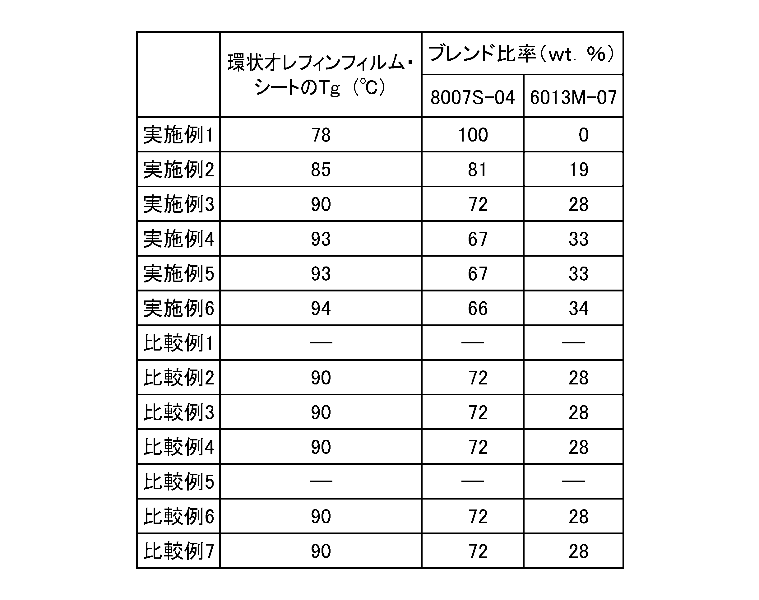
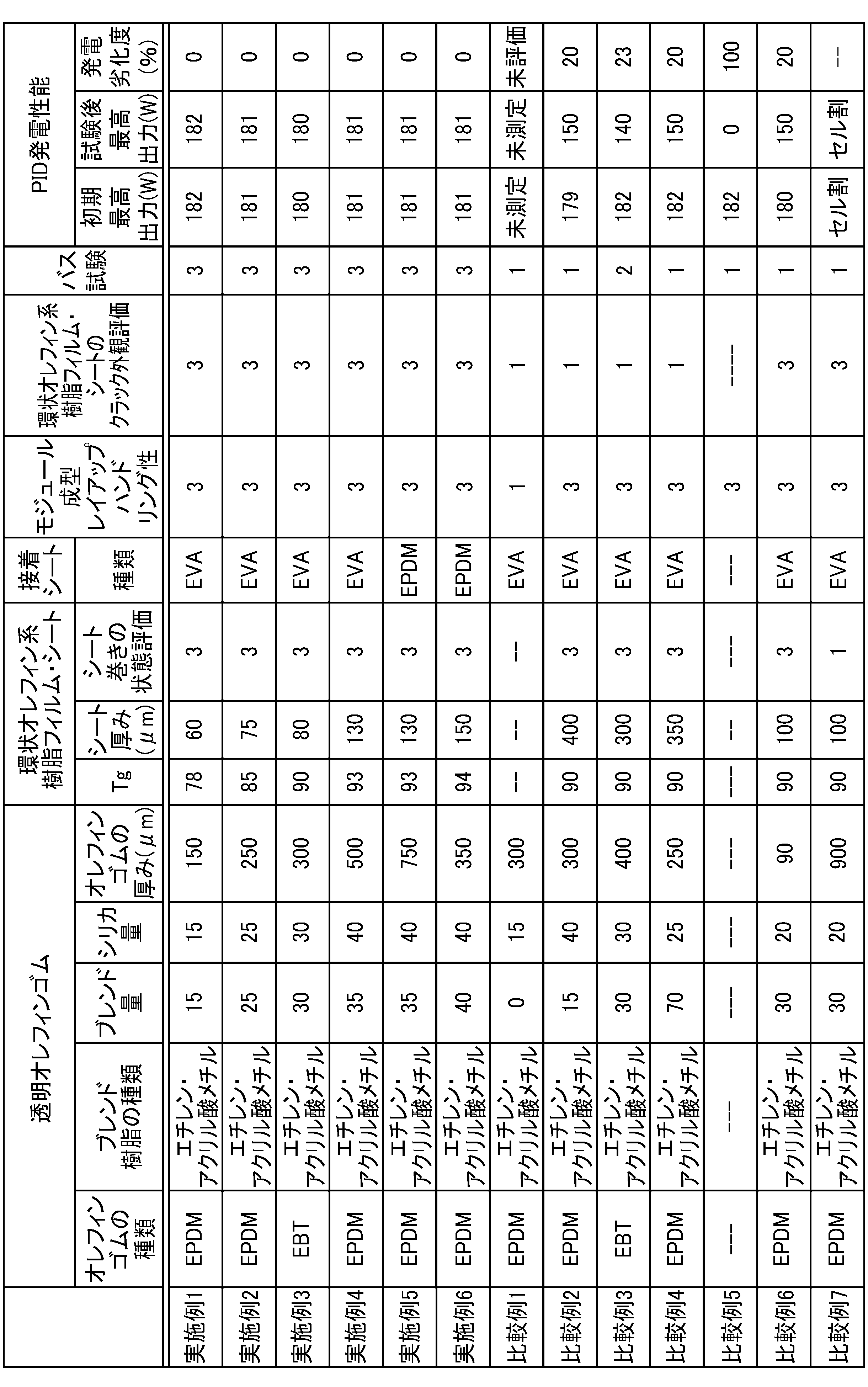
Claims (9)
- ガラス転移温度が75℃から95℃であり厚みが50μmから200μmである環状オレフィン系樹脂のフィルムと
エチレン・α-オレフィンゴム共重合体(A)とエチレン・アクリル酸共重合体(B)を配合比(A/B)が60/40から90/10の比率でブレンドした透明オレフィン系ゴム組成物100重量部に、シリカを10重量部から50重量部添加し、さらに、有機過酸化物架橋剤を含む透明オレフィン系ゴム材料であって、その厚みが100μmから800μmであるシートと
積層し一体化したことを特徴とする太陽電池モジュール用封止シート。 - エチレン・α-オレフィンゴム共重合体(A)とエチレン・アクリル酸共重合体(B)を配合比(A/B)が60/40から90/10の比率でブレンドした透明オレフィン系ゴム組成物100重量部に、シリカを10重量部から50重量部添加し、さらに、有機過酸化物架橋剤を含む透明オレフィン系ゴム材料であって、その厚みが100μmから800μmであるシートを
ガラス転移温度が75℃から95℃であり厚みが50μmから200μmである環状オレフィン系樹脂のフィルムの両側(両面)に設け一体化したことを特徴とする太陽電池モジュール用封止シート。 - 環状オレフィン系樹脂が、エチレンおよび/またはα-オレフィンと、環状オレフィンとの共重合体であることを特徴とする請求項1または請求項2に記載の太陽電池モジュール用封止シート。
- 請求項1から請求項3のいずれかに記載の太陽電池モジュール用封止シートを使用したことを特徴とする太陽電池モジュール。
- 太陽電池モジュールの透明基体と、請求項1に記載の封止シートの間に、既存の太陽電池用封止シートを設けたことを特徴とする太陽電池モジュール。
- 太陽電池モジュールのカバーガラスと、請求項1に記載の封止シートの間に、既存の太陽電池用封止シートを設けたことを特徴とする太陽電池モジュール。
- 太陽電池モジュールの透明基体と、請求項2に記載の封止シートの間に、既存の太陽電池用封止シートを用いた設けたことを特徴とする太陽電池モジュール。
- 太陽電池モジュールのカバーガラスと、請求項2に記載の封止シートの間に、既存の太陽電池用封止シートを用いた設けたことを特徴とする太陽電池モジュール。
- 請求項1から請求項3のいずれかをに記載の封止シートを含む太陽電池モジュール用の構成部材を積層体とし、前記積層体を120℃以上の温度で成型することにより、それぞれの界面が接着していることを特徴とする太陽電池モジュール。
Applications Claiming Priority (4)
| Application Number | Priority Date | Filing Date | Title |
|---|---|---|---|
| JP2014-034405 | 2014-02-25 | ||
| JP2014034405 | 2014-02-25 | ||
| JP2015028551A JP6310869B2 (ja) | 2014-02-25 | 2015-02-17 | Pid対策・発電劣化対策太陽電池封止シートおよびpid対策・発電劣化対策太陽電池モジュール |
| JP2015-028551 | 2015-02-17 |
Publications (1)
| Publication Number | Publication Date |
|---|---|
| WO2015129596A1 true WO2015129596A1 (ja) | 2015-09-03 |
Family
ID=54008916
Family Applications (1)
| Application Number | Title | Priority Date | Filing Date |
|---|---|---|---|
| PCT/JP2015/054926 Ceased WO2015129596A1 (ja) | 2014-02-25 | 2015-02-23 | Pid対策・発電劣化対策太陽電池封止シートおよびpid対策・発電劣化対策太陽電池モジュール |
Country Status (3)
| Country | Link |
|---|---|
| JP (1) | JP6310869B2 (ja) |
| TW (1) | TW201607061A (ja) |
| WO (1) | WO2015129596A1 (ja) |
Cited By (2)
| Publication number | Priority date | Publication date | Assignee | Title |
|---|---|---|---|---|
| JP2021510742A (ja) * | 2017-10-31 | 2021-04-30 | ダウ グローバル テクノロジーズ エルエルシー | 太陽光発電封止材フィルムのためのポリオレフィン組成物 |
| WO2025188267A1 (en) * | 2024-03-06 | 2025-09-12 | Kalyon Gunes Teknolojileri Uretim Anonim Sirketi | An encapsulant material suitable for use in photovoltaic modules |
Citations (7)
| Publication number | Priority date | Publication date | Assignee | Title |
|---|---|---|---|---|
| WO2006095762A1 (ja) * | 2005-03-08 | 2006-09-14 | Du Pont/Mitsui Polychemicals Co. Ltd. | 太陽電池封止材 |
| WO2011108600A1 (ja) * | 2010-03-02 | 2011-09-09 | 三菱樹脂株式会社 | 太陽電池封止材及びそれを用いて作製された太陽電池モジュール |
| JP2013041911A (ja) * | 2011-08-12 | 2013-02-28 | Polyplastics Co | 太陽電池用接着シート及びその製造方法、並びに太陽電池モジュール |
| WO2013128861A1 (ja) * | 2012-02-29 | 2013-09-06 | 三井化学東セロ株式会社 | 太陽電池封止用シートセット |
| JP2013211451A (ja) * | 2012-03-30 | 2013-10-10 | Mitsubishi Plastics Inc | 太陽電池用封止材・表面保護シート積層体 |
| JP2014022473A (ja) * | 2012-07-13 | 2014-02-03 | Nisshinbo Holdings Inc | 太陽電池モジュール |
| JP2014029953A (ja) * | 2012-07-31 | 2014-02-13 | Mitsui Chemicals Inc | 太陽電池封止材および太陽電池モジュール |
Family Cites Families (1)
| Publication number | Priority date | Publication date | Assignee | Title |
|---|---|---|---|---|
| EP2572877A3 (en) * | 2011-09-20 | 2013-05-29 | RENOLIT Belgium N.V. | Photovoltaic modules comprising a backsheet and electrical insulating layer(s) which are highly permeable to corrosive degradation by-products |
-
2015
- 2015-02-17 JP JP2015028551A patent/JP6310869B2/ja not_active Expired - Fee Related
- 2015-02-23 WO PCT/JP2015/054926 patent/WO2015129596A1/ja not_active Ceased
- 2015-02-24 TW TW104105850A patent/TW201607061A/zh unknown
Patent Citations (7)
| Publication number | Priority date | Publication date | Assignee | Title |
|---|---|---|---|---|
| WO2006095762A1 (ja) * | 2005-03-08 | 2006-09-14 | Du Pont/Mitsui Polychemicals Co. Ltd. | 太陽電池封止材 |
| WO2011108600A1 (ja) * | 2010-03-02 | 2011-09-09 | 三菱樹脂株式会社 | 太陽電池封止材及びそれを用いて作製された太陽電池モジュール |
| JP2013041911A (ja) * | 2011-08-12 | 2013-02-28 | Polyplastics Co | 太陽電池用接着シート及びその製造方法、並びに太陽電池モジュール |
| WO2013128861A1 (ja) * | 2012-02-29 | 2013-09-06 | 三井化学東セロ株式会社 | 太陽電池封止用シートセット |
| JP2013211451A (ja) * | 2012-03-30 | 2013-10-10 | Mitsubishi Plastics Inc | 太陽電池用封止材・表面保護シート積層体 |
| JP2014022473A (ja) * | 2012-07-13 | 2014-02-03 | Nisshinbo Holdings Inc | 太陽電池モジュール |
| JP2014029953A (ja) * | 2012-07-31 | 2014-02-13 | Mitsui Chemicals Inc | 太陽電池封止材および太陽電池モジュール |
Cited By (3)
| Publication number | Priority date | Publication date | Assignee | Title |
|---|---|---|---|---|
| JP2021510742A (ja) * | 2017-10-31 | 2021-04-30 | ダウ グローバル テクノロジーズ エルエルシー | 太陽光発電封止材フィルムのためのポリオレフィン組成物 |
| JP7064585B2 (ja) | 2017-10-31 | 2022-05-10 | ダウ グローバル テクノロジーズ エルエルシー | 太陽光発電封止材フィルムのためのポリオレフィン組成物 |
| WO2025188267A1 (en) * | 2024-03-06 | 2025-09-12 | Kalyon Gunes Teknolojileri Uretim Anonim Sirketi | An encapsulant material suitable for use in photovoltaic modules |
Also Published As
| Publication number | Publication date |
|---|---|
| TW201607061A (zh) | 2016-02-16 |
| JP2015179827A (ja) | 2015-10-08 |
| JP6310869B2 (ja) | 2018-04-11 |
Similar Documents
| Publication | Publication Date | Title |
|---|---|---|
| JP6914841B2 (ja) | 太陽電池封止材用多層シート、太陽電池封止材用多層シートの製造方法および太陽電池モジュール | |
| CN104081539B (zh) | 太阳能电池用密封膜和使用该膜的太阳能电池 | |
| US8222514B2 (en) | Backskin material for solar energy modules | |
| WO2014080856A1 (ja) | 太陽電池封止材および太陽電池モジュール | |
| EP3357987B1 (en) | Insulating multilayer sheet and solar cell module | |
| MX2008010952A (es) | Evm en modulos solares. | |
| JP6310869B2 (ja) | Pid対策・発電劣化対策太陽電池封止シートおよびpid対策・発電劣化対策太陽電池モジュール | |
| US12297336B2 (en) | Multilayer assembly comprising silane-grafted polyolefin | |
| JP2016213401A (ja) | 太陽電池用封止材製造用組成物 | |
| JP2015179826A (ja) | 太陽電池用セル割れ防止シート及びそれを用いた太陽電池モジュール | |
| WO2014054579A1 (ja) | 太陽電池モジュール用充填材シート及び太陽電池モジュールの製造方法 | |
| JP7410179B2 (ja) | 太陽電池封止材用樹脂組成物、太陽電池封止材、太陽電池封止材の製造方法および太陽電池モジュール | |
| NL2008841C2 (en) | Multilayer backsheet for photovoltaic modules. | |
| JP2017107922A (ja) | 太陽電池モジュール用封止材および太陽電池モジュール | |
| JP2017162874A (ja) | 太陽電池モジュール用封止材および太陽電池モジュール | |
| JP2017162873A (ja) | 太陽電池モジュール用封止材および太陽電池モジュール | |
| JP2017123364A (ja) | 太陽電池モジュール用封止材及び太陽電池モジュール | |
| JP2015046509A (ja) | 太陽電池モジュール用封止材及び太陽電池モジュール | |
| JP2017107923A (ja) | 太陽電池モジュール用封止材および太陽電池モジュール |
Legal Events
| Date | Code | Title | Description |
|---|---|---|---|
| 121 | Ep: the epo has been informed by wipo that ep was designated in this application |
Ref document number: 15754462 Country of ref document: EP Kind code of ref document: A1 |
|
| NENP | Non-entry into the national phase |
Ref country code: DE |
|
| 122 | Ep: pct application non-entry in european phase |
Ref document number: 15754462 Country of ref document: EP Kind code of ref document: A1 |