WO2015129337A1 - 表層流推定装置、表層流推定システム、海洋モデル推定装置、及び危険度判定装置 - Google Patents
表層流推定装置、表層流推定システム、海洋モデル推定装置、及び危険度判定装置 Download PDFInfo
- Publication number
- WO2015129337A1 WO2015129337A1 PCT/JP2015/051301 JP2015051301W WO2015129337A1 WO 2015129337 A1 WO2015129337 A1 WO 2015129337A1 JP 2015051301 W JP2015051301 W JP 2015051301W WO 2015129337 A1 WO2015129337 A1 WO 2015129337A1
- Authority
- WO
- WIPO (PCT)
- Prior art keywords
- ship
- estimator
- flow estimation
- surface layer
- speed
- Prior art date
- Legal status (The legal status is an assumption and is not a legal conclusion. Google has not performed a legal analysis and makes no representation as to the accuracy of the status listed.)
- Ceased
Links
Images











Classifications
-
- G—PHYSICS
- G01—MEASURING; TESTING
- G01P—MEASURING LINEAR OR ANGULAR SPEED, ACCELERATION, DECELERATION, OR SHOCK; INDICATING PRESENCE, ABSENCE, OR DIRECTION, OF MOVEMENT
- G01P5/00—Measuring speed of fluids, e.g. of air stream; Measuring speed of bodies relative to fluids, e.g. of ship, of aircraft
-
- B—PERFORMING OPERATIONS; TRANSPORTING
- B63—SHIPS OR OTHER WATERBORNE VESSELS; RELATED EQUIPMENT
- B63B—SHIPS OR OTHER WATERBORNE VESSELS; EQUIPMENT FOR SHIPPING
- B63B79/00—Monitoring properties or operating parameters of vessels in operation
- B63B79/10—Monitoring properties or operating parameters of vessels in operation using sensors, e.g. pressure sensors, strain gauges or accelerometers
- B63B79/15—Monitoring properties or operating parameters of vessels in operation using sensors, e.g. pressure sensors, strain gauges or accelerometers for monitoring environmental variables, e.g. wave height or weather data
-
- B—PERFORMING OPERATIONS; TRANSPORTING
- B63—SHIPS OR OTHER WATERBORNE VESSELS; RELATED EQUIPMENT
- B63B—SHIPS OR OTHER WATERBORNE VESSELS; EQUIPMENT FOR SHIPPING
- B63B49/00—Arrangements of nautical instruments or navigational aids
Definitions
- the present invention relates to a surface current estimation device and a surface current estimation system for estimating the velocity of a surface current, which is the flow of seawater in the surface layer portion of the ocean, as well as an ocean model estimation device and a risk determination device using them. .
- Patent Document 1 Conventionally, as a method for estimating the velocity of the surface current, which is the tide flow in the surface layer portion of the ocean, for example, a method as shown in Patent Document 1 is known. Specifically, in Patent Document 1, surface flow velocity (surface flow velocity) is obtained by applying Fourier transform to a received signal obtained by an ocean radar.
- the present invention is for solving the above-mentioned problems, and its purpose is to easily calculate the velocity of the surface layer flow.
- a surface flow estimation device estimates a surface flow velocity vector that is a surface flow velocity vector at a target point where a ship is located at sea.
- an estimator that estimates and outputs a value corresponding to each condition specified by the received combination of the values as the water speed vector of the ship, and the water resistance estimated by the estimator Based on the output value as a speed vector and the ground speed vector calculated by the ground speed calculation unit, the table at the target point.
- a surface current calculation unit for calculating a flow velocity vector It has.
- the ground speed is the speed relative to the ground
- the water speed is the speed relative to water (seawater).
- the estimator is configured to output, as the output value, an average value of a plurality of ground speed vectors corresponding to the respective conditions using a neural network.
- the surface flow estimator compares the output value from the estimator with the ground speed vector calculated by the ground speed calculator, and the output value and the ground speed vector.
- An update unit that updates the estimator is further provided so as to reduce an error with the estimator.
- the estimator is configured using a neural network, each of which includes at least one input unit to which any one of the at least one parameter is input, and the water velocity vector.
- An output unit for outputting the output value as a value, and a value output from an input side unit in the neural network is multiplied by a coupling coefficient and then transmitted to the output side unit, and the updating unit Compares the output value with the ground speed vector as a teacher signal, and updates the coupling coefficient so that an error between the output value and the teacher signal is reduced.
- the surface flow velocity calculation unit subtracts the water velocity vector estimated by the estimator from the ground velocity vector calculated by the ground velocity calculation unit. Calculate the vector.
- the surface current estimation device is further provided with a GNSS signal receiving unit that is mounted on the ship and receives a GNSS signal, and the ground speed calculation unit is a GNSS signal received by the GNSS signal receiving unit. And the ground speed vector is calculated based on the time when the GNSS signal is received.
- the parameters include information on the number of rotations of the propeller of the ship, wind direction and wind speed, information on the rudder angle of the ship, draft of the ship, information on waves, roll angle of the ship, pitch angle of the ship , The amount of heave of the ship, information on sea conditions, information on weather, or position information.
- the surface layer flow estimation device further includes a propeller rotational speed detection unit that detects the rotational speed of the propeller, and a wind speed anemometer mounted on the ship, and the estimator includes: At least the rotation speed of the propeller detected by the propeller rotation speed detector and the information on the wind direction and the wind speed measured by the wind speed anemometer are input.
- the surface layer flow estimation device is mounted on the ship as the ship.
- a surface flow estimation system is a ground surface of any of the above-described surface flow estimation devices mounted in a place different from the ship as the ship.
- a calculation unit having a speed calculation unit, an estimator, and a surface flow calculation unit; and a value of the at least one parameter mounted on the own ship and affecting the water velocity vector of the own ship to the calculation unit.
- the calculation unit also calculates the surface layer flow velocity vector at a point where the other ship is located based on the value of the at least one parameter in the other ship,
- the reception unit also receives the surface flow velocity vector calculated by the calculation unit at the point where the other ship is located.
- the surface flow estimation system displays a desired region on the sea, the surface flow velocity vector at the target point of the ship in the region, and the other ship in the region. And a display unit capable of displaying the surface layer flow velocity vector at a point where is located.
- an ocean model estimation device includes any one of the above-described surface flow estimation devices or any of the above-described surface flow estimation systems, and the surface layer
- the estimator of the flow estimation device or the surface layer flow estimation system is provided as a first estimator, is configured using a neural network, and receives and receives the position information of the ship and current marine weather information.
- a value corresponding to each condition specified by the combination of each information is output as an output value, and a surface flow velocity vector as the teacher signal calculated by the surface flow estimation device or the surface flow estimation system and the output value
- a second estimator that is updated so as to reduce an error with
- a risk determination device includes any one of the above-described surface flow estimation devices or any of the above-described surface flow estimation systems, and at least the above-mentioned A determination unit that determines a wave risk level for the ship based on a surface flow velocity vector estimated by the surface flow estimation device or the surface flow estimation system.
- a water speed estimation device for estimating a water speed vector of a ship at a target point where the ship is located at sea, wherein the rotation speed of the propeller of the ship and The input of the value at the target point of the information on the wind direction and the wind speed acting on the ship is accepted, and the value corresponding to each condition specified by the combination of the accepted values is the water speed of the ship.
- An estimator that estimates and outputs a vector is provided.
- an acoustic water speed meter is used as an example.
- a large-scale installation work such as making a hole in the ship bottom is required.
- the water speed estimation device for solving the above-described problem, and its purpose is to easily estimate the water speed vector without requiring a large-scale installation work on the ship. That is.
- the water speed of the ship can be obtained based on the information on the rotation speed of the ship, the wind direction and the wind speed, which can be obtained relatively easily. .
- the water velocity vector can be easily estimated without requiring a large-scale mounting operation on the ship.
- the estimator is configured using a neural network.
- the estimator which estimates a water velocity vector can be comprised appropriately.
- the estimator further includes a propeller rotational speed detection unit that detects the rotational speed of the propeller, and an anemometer installed on the ship. Is inputted with the rotation speed of the propeller detected by the propeller rotation speed detector and the information on the wind direction and the wind speed measured by the anemometer.
- a propeller rotational speed detection unit that detects the rotational speed of the propeller
- an anemometer installed on the ship. Is inputted with the rotation speed of the propeller detected by the propeller rotation speed detector and the information on the wind direction and the wind speed measured by the anemometer.
- Many general ships are provided with a propeller rotation speed detector and an anemometer. Therefore, by utilizing these, the water velocity vector can be estimated without installing a new device for detecting the water velocity vector on the ship.
- the velocity of the surface layer flow can be easily calculated.
- FIG. 1 It is a block diagram which shows the structure of the surface layer flow estimation apparatus which concerns on a modification. It is a block diagram which shows the structure of the surface layer flow estimation apparatus which concerns on a modification. It is a block diagram which shows the structure of the learning coefficient setting process part shown in FIG. It is a figure which shows typically the table memorize
- a surface layer flow estimation apparatus 1 is mounted on a ship (ship).
- the surface flow estimation apparatus 1 estimates the direction and magnitude of the surface flow at the ship position, that is, the velocity vector of the surface flow at the ship position.
- predetermined parameters in this embodiment, the rotation speed of the propeller of the ship, the true wind speed in the bow direction, and the true wind speed on the starboard direction
- the surface flow velocity surface flow velocity vector
- the surface layer flow in the present embodiment is a flow in a depth range of a range from the sea surface to the ship bottom of the ship.
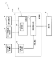
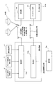
- FIG. 1 is a block diagram showing a configuration of a surface layer flow estimation apparatus 1 according to an embodiment of the present invention.
- the surface layer flow estimation apparatus 1 includes a GPS signal receiving unit 2, a propeller rotation number detection unit 3, an anemometer 4, a calculation unit 10, and a display unit 5.
- the GPS signal receiving unit 2 is provided as a GNSS signal receiving unit for receiving a GPS signal as a navigation signal (GNSS signal) transmitted from a navigation satellite (not shown).
- the GPS signal receiving unit 2 is configured by, for example, a GPS antenna.
- the GPS signal received by the GPS signal receiving unit 2 (that is, the position information of the ship) is notified to the calculation unit 10 together with the time when the GPS signal is received.
- GNSS Global Navigation Satellite System
- GALILEO Global Navigation Satellite System
- GLONASS Global Navigation Satellite System
- the propeller rotational speed detection unit 3 is for detecting the rotational speed per unit time of the propeller for generating the thrust of the ship, and is constituted by a sensor capable of detecting the rotational speed, for example. The rotation speed detected by the propeller rotation speed detection unit 3 is notified to the calculation unit 10.
- the wind direction anemometer 4 is for measuring the true wind speed in the bow direction and the true wind speed in the starboard direction as information on the wind direction and the wind speed.
- the anemometer 4 is installed in a place where there are no obstacles that block the wind in the ship where the surface flow estimation device 1 according to the present embodiment is mounted.
- the bow direction true wind speed and starboard direction true wind speed measured by the anemometer 4 are notified to the calculation unit 10.
- the calculation unit 10 estimates the surface layer flow at the ship position (target point) at each predetermined timing based on various information notified from the GPS signal reception unit 2, the propeller rotation number detection unit 3, and the wind direction anemometer 4. To do.
- the calculation unit 10 includes a ground speed calculation unit 11, an estimator 12, a surface layer flow calculation unit 13, and a coupling coefficient update unit 14.
- the ground speed calculation unit 11 calculates the ground speed (ground speed vector) of the ship based on the position information of the ship notified from the GPS signal receiving unit 2 and the time when the ship position information is acquired. Specifically, the ground speed calculation unit 11 calculates the ground speed of the ship based on the ship position at at least two timings and the time when the position information of each ship position is acquired. The ground speed calculation unit 11 notifies the surface speed calculated in this way to the surface layer flow calculation unit 13 and the coupling coefficient update unit 14.
- the estimator 12 is configured to estimate the water speed of the ship.
- the estimator 12 receives the propeller rotation speed detected by the propeller rotation speed detector 3 and the bow direction true wind speed and starboard direction true wind speed measured by the anemometer.
- the estimator 12 calculates a value corresponding to a condition specified by a combination of these input values (a condition specified by a combination of a certain rotation speed, a certain bow direction true wind speed, and a certain starboard direction true wind speed) to the water speed.
- Water speed vector in this embodiment, bow direction water speed and starboard direction water speed
- FIG. 2 is a diagram schematically illustrating an example of the configuration of the estimator 12.
- the estimator 12 is configured using a generally known neural network. Specifically, the estimator 12, a plurality of input units U IN_1 constituting the input layer, U IN_2, a U IN_3, a plurality of intermediate units U MID_1 constituting the hidden layer, U MID_2, a U MID_3, output layer Output units U OUT — 1 and U OUT — 2 are included.
- the configuration of the estimator 12 shown in FIG. 2 is merely an example, and the number of units in each layer and the number of hidden layers are not limited to those shown in FIG.
- the estimator 12 each of the input units U IN_1, U IN_2, when the input value U IN_3 (rotational speed of the propeller, etc.) is input, the coupling coefficient W I for those input values, M is multiplied , And output to the hidden layer intermediate units U MID — 1 , U MID — 2 and U MID — 3 .
- Each of the hidden layer intermediate units U MID — 1 , U MID — 2 and U MID — 3 sums the input values and multiplies the values based on the total values by the coupling coefficients W M, O to the output units U OUT — 1 and U OUT — 2 . Output.
- the output units U OUT — 1 and U OUT — 2 sum the input values and output the values based on the total values to the surface flow calculation unit 13 and the coupling coefficient update unit 14 as output values.
- the value input to the estimator 12 does not necessarily have to be a parameter value itself such as a propeller rotational speed, but is a numerical value having a one-to-one relationship with those parameters (for example, proportional to the rotational speed). Or a voltage value that changes).
- each coupling coefficient W is updated by the coupling coefficient updating unit 14 as needed.
- each coupling coefficient W includes a coupling coefficient update unit so that an error between the output value output from the estimator 12 and the ground speed (teacher signal) calculated by the ground speed calculation unit 11 is reduced. 14 is updated. As a result, the output value output from the estimator 12 converges to the water speed of the ship every time the coupling coefficient W is updated, as will be described in detail later.
- the surface layer flow calculation unit 13 is based on the output value as the water velocity output from the estimator 12 and the ground velocity calculated by the ground velocity calculation unit 11. Vector). Specifically, the surface layer flow calculation unit 13 calculates the surface layer flow velocity by subtracting the water velocity from the ground velocity.
- Figure 3 is a vector diagram illustrating the ground speed vector V G, and to water velocity vector V W, the relationship between the surface layer flow velocity vector V T.
- the ground speed V G is a speed with respect to the ground surface
- the water speed V W is a speed with respect to the water surface (sea surface).
- a surface current is a flow of water in the surface layer of the sea. Therefore, the relationship between the ground velocity vector V G , the water velocity vector V W , and the surface layer velocity vector V T can be expressed as shown in FIG. Therefore, the surface layer flow calculation unit 13 subtracts the water velocity V W from the ground velocity V G as described above, thereby calculating the surface layer flow velocity V T.
- the coupling coefficient update unit 14 sets the coupling coefficient W of the estimator 12 so that an error between the output value output from the estimator 12 and the ground speed (teacher signal) calculated by the ground speed calculation unit 11 is reduced. Update.
- the coupling coefficient updating unit 14 updates the coupling coefficient W by using back propagation (error back propagation method), for example.
- the display unit 5 displays the direction and size of the surface flow calculated by the surface flow calculation unit 13. Thereby, the user can know the velocity of the surface layer flow at the ship position.
- FIG. 4 is a diagram for explaining the reason why the output value output from the estimator 12 converges to the water velocity every time the coupling coefficient W of the estimator 12 is updated.
- each coupling coefficient W stored in the estimator 12 has a coupling coefficient W so that an error between a value output from the estimator 12 and the ground speed as a teacher signal calculated from time to time becomes small. It is updated by the update unit 14.
- the surface current is different in size and direction due to the sea area, time, weather conditions, and the like. Therefore, the ground speed when the water speed is the same (that is, when the speed of the propeller, the true wind speed in the bow direction, and the true wind speed in the starboard direction are the same) includes components of surface flow velocity of any magnitude and direction. It is thought that. Therefore, when these are averaged (V G1 to V G6 in the case of FIG. 4 are averaged), the surface layer flow velocity components cancel each other, and the water velocity component remains. That is, when the coupling coefficient W of the estimator 12 is updated so that the error between the output value of the estimator 12 and the ground speed becomes small as described above, the influence of the surface flow velocity component included in the ground speed.
- the output value of the estimator 12 converges to the water speed. Accordingly, when the learning is sufficiently advanced (that is, when the coupling coefficient is updated a sufficient number of times), the output value from the estimator 12 can be estimated as the water velocity.
- the rotational speed is detected by the propeller rotational speed detection unit 3 at every predetermined timing during navigation of the ship, and the true wind speed in the bow direction and the true wind speed in the starboard direction are measured by the wind direction anemometer 4. These pieces of information are output to the estimator 12 as needed. Based on these, the estimator 12 generates the output value using a coupling coefficient W that is updated as needed during the navigation of the ship.
- the water speed estimation apparatus which estimates a water speed is comprised by the propeller rotation speed detection part 3, the wind direction anemometer 4, and the estimator 12 in this embodiment.
- the water speed estimation device may include a GPS signal receiver 2, a ground speed calculator 11, and a coupling coefficient updater 14. By displaying the water speed (the output value of the estimator 12) estimated by the water speed estimation apparatus on the display unit 5, the water speed can be notified to the user.
- the propeller rotation speed detection part, the wind direction anemometer, and the estimator in each modification described below can also be used as a water speed estimation device that estimates the water speed, as in the above-described case.
- the surface current estimation apparatus 1 calculates the surface current based on the ground speed calculated by the ground speed calculation unit 11 and the water speed estimated by the estimator 12. Yes. Thereby, the surface layer flow near the sea surface that has a relatively large influence on the movement of the ship can be estimated relatively easily.
- the velocity of the surface layer flow can be easily calculated.
- the estimator 12 is configured using a neural network. Thereby, the estimator 12 capable of outputting the water speed can be appropriately configured.
- the estimator 12 is updated so that an error between the output value of the estimator 12 and the ground speed calculated by the ground speed calculation unit 11 is reduced. Thereby, the estimator 12 provided with the learning function can be configured. Moreover, since the surface flow estimation apparatus 1 can accumulate a large amount of data necessary for estimating an accurate water velocity during navigation, learning data (ground velocity data under certain conditions) is prepared in advance. This saves you time and effort.
- the estimator 12 since the estimator 12 is updated using real-time data acquired while navigating, the ship position cannot be obtained from tidal current information distributed from a public institution, for example. It is possible to know the local surface current.
- the estimator 12 since the estimator 12 is updated using real-time data as described above, the estimator 12 corresponds to the current state of the ship (such as aged deterioration, fouling state). Is updated. As a result, the surface layer flow can be accurately estimated regardless of the ship state.
- the coupling coefficient W stored in the estimator 12 is updated so that the error between the output value of the estimator 12 and the ground speed calculated by the ground speed calculator 11 is reduced. ing. Thereby, the estimator 12 can be updated appropriately.
- the surface flow estimation device 1 calculates the surface flow velocity by subtracting the water velocity from the ground velocity. Thereby, the surface layer flow velocity can be calculated more easily.
- the surface layer flow estimation apparatus 1 can accurately calculate the ground speed by using GNSS, which is widely spread, particularly GPS. Moreover, since a general ship is often equipped with a GPS antenna, the ground speed can be calculated without introducing a new device or the like.
- the estimator 12 is a combination of the values of the rotation speed of the ship propeller, the true wind speed in the bow direction, and the true wind speed in the starboard direction, which are parameters that greatly affect the water speed of the ship.
- the water velocity at the time specified by is estimated. Thereby, the water velocity can be efficiently estimated using relatively few parameters. Moreover, since these parameters can be measured relatively easily, the water velocity can be easily estimated.
- the surface flow estimation device 1 detects the rotation speed of the propeller, the true wind speed in the bow direction, and the true wind speed in the starboard direction by the propeller rotation speed detection unit 3 and the wind direction anemometer 4 mounted on the ship. Since a general ship is often equipped with such a detection unit 3 and an anemometer 4, the surface flow velocity can be estimated without installing a new sensor or the like.
- the surface layer flow estimation apparatus 1 is mounted on the own ship. This makes it possible to estimate the surface flow velocity near the ship.
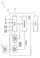
- FIG. 5 is a block diagram showing a configuration of a surface layer flow estimation apparatus 1a according to a modification. Unlike the surface flow estimation apparatus 1 shown in FIG. 1, the surface flow estimation apparatus 1a according to this modification has a configuration in which the coupling coefficient update unit 14 is omitted. That is, the surface layer flow estimation apparatus 1a according to this modification does not have a learning function.
- the estimator 12a in which the coupling coefficient W is determined based on a lot of previously acquired learning data (ground speed data under certain conditions) Output value is output. Even with such a configuration, the surface layer flow can be easily calculated as in the case of the above embodiment.
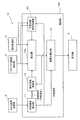
- FIG. 6 is a block diagram showing a configuration of the surface layer flow estimation apparatus 1b according to the modification.
- the surface layer flow estimation apparatus 1b according to the present modification is significantly different from the surface layer flow estimation apparatus 1 according to the embodiment in the configuration of the estimator 12b.
- the estimator 12b is not configured using a neural network, but includes a storage unit 15 and an update unit 16.
- FIG. 7 is a diagram for explaining the estimator 12b shown in FIG. 6 in detail.
- the storage unit 15 stores a matrix table.
- each condition (corresponding to each cell of the table) specified by a combination of each value (X1, X2, X3,%) Of the wind speed and wind direction and each value (R1, R2, R3,%) Of the rotational speed.
- the ground speed calculated at the time of is stored.
- one ground speed value is indicated by one circle. That is, the storage unit 15 stores, for example, five ground speed values calculated when the value of the wind speed and the wind direction is X1 and the value of the rotational speed is R1.
- the estimator 12b When the rotational speed (for example, R2) detected by the propeller rotational speed detection unit 3 and the wind direction wind speed (for example, X3) measured by the wind direction anemometer 4 are input to the estimator 12b, the estimator 12b An average value of ground speeds (11 in the case of FIG. 7) included in the cell having the rotation speed R2 and the wind direction and wind speed X3 is calculated. Then, the estimator 12b outputs the average value as an output value.
- the surface flow velocity components included in the ground speed cancel each other. Therefore, the average value is close to the water velocity. Therefore, the water speed can be appropriately estimated also by the estimator 12b according to this modification.
- the update unit 16 updates the table stored in the storage unit 15 using the ground speed calculated at the timing when the rotation speed and the wind direction and the wind speed input to the estimator 12b are detected. Specifically, the ground speed calculated for a predetermined rotation speed (for example, R3) and a predetermined wind direction and wind speed (for example, X2) is added to the cell specified by R3 and X2. By performing this operation as needed, learning data is accumulated even during navigation, and the water speed can be estimated more accurately. That is, the estimator 12b according to this modification also has a learning function. As a result, the surface layer flow velocity can be calculated more accurately.
- a predetermined rotation speed for example, R3
- a predetermined wind direction and wind speed for example, X2
- a surface flow estimation device 1c having no learning function can be configured (see FIG. 8). In this case, it is necessary to store a plurality of learning data (data corresponding to one circle in FIG. 7) obtained in advance in the storage unit 15.
- FIG. 9 is a block diagram showing a configuration of a surface layer flow estimation apparatus 1d according to a modification.
- the estimator 12d As input values to be input to the estimator 12d, in addition to the rotation speed of the propeller, the true wind speed in the bow direction, and the true wind speed in the starboard direction, the rudder angle, draft (from the bottom of the ship in a floating state) The distance to the water surface) is entered. Then, the estimator 12d outputs a value corresponding to each condition specified by the combination of each value of each parameter as an output value. As a result, more parameters can be taken into consideration as parameters affecting the water speed, so that the water speed can be determined more accurately.
- parameters input to the estimator 12d information on waves, ship roll angle, ship pitch angle, ship heave amount, information on sea conditions, weather information, position Information, etc. can also be included. Thereby, a more accurate water velocity can be obtained.
- FIG. 10 is a block diagram showing a configuration of the surface layer flow estimation apparatus 1e according to the modification.
- the surface layer flow estimation apparatus 1e according to this modification further includes a learning coefficient setting processing unit 20.
- the estimator 12e is configured using a neural network as in the case of the above embodiment, and is configured so that the coupling coefficient is updated as needed by so-called supervised learning.
- an error between the output value from the estimator 12e and the teacher signal (ground speed) is calculated.
- the surface layer flow estimation device 1e updates the coupling coefficient W while propagating the error as a learning signal from the unit on the output layer side to the unit on the input layer side.
- the correction amount of the coupling coefficient is given by the following equation (1).
- ⁇ W i, j n, n ⁇ 1 (t) is a correction amount for the weight of the coupling between the unit j of the n ⁇ 1 layer and the unit i of the n layer
- ⁇ is a learning coefficient
- ⁇ i n is a learning signal returned from the unit i of the nth layer to each unit of the n ⁇ 1 layer
- X j n ⁇ 1 is an output value of the unit j of the n ⁇ 1 layer
- ⁇ is a stabilization coefficient
- ⁇ W i, j n , n-1 (t-1) indicates the previous correction amount.
- the n-1th layer is one layer on the input side than the nth layer.
- FIG. 11 is a block diagram illustrating a configuration of the learning coefficient setting processing unit 20.
- the learning coefficient setting processing unit 20 is for setting the learning coefficient in Expression (1) as needed.
- the learning coefficient setting processing unit 20 includes a storage unit 21, an SOM update unit 22, a count unit 23, a learning coefficient calculation unit 24, and a learning coefficient setting unit 25. .
- FIG. 12 is a diagram schematically showing a table stored in the storage unit 21 and a self-organizing map SOM stored corresponding to each cell of the table.
- the storage unit 21 stores a table cut in a mesh shape for each predetermined propeller rotation speed and for each predetermined wind speed and wind direction.
- a corresponding self-organizing map SOM is stored in each cell of this table.
- Each self-organizing map SOM of this modification is a two-dimensional SOM composed of n ⁇ n units.
- Each unit stores a reference vector having the same dimension as the input vector. In an initial state (a state in which learning is not performed), an appropriate reference vector is set for each unit.
- the SOM update unit 22 updates the SOM according to an input vector (a vector composed of a propeller rotation speed, a wind direction, a wind speed, a ground speed, and the like input at every predetermined timing). Specifically, the SOM update unit 22 updates the SOM stored in the cell including the input rotation speed and wind direction and wind speed as follows.
- the SOM update unit 22 sets the unit having the shortest Euclidean distance from the input vector as the winner unit, the reference vector stored in the winner unit, and the reference vector stored in units around the winner unit. Is updated based on the following equation (2).
- m i is a reference vector
- x (t) is an input vector
- h i is a neighborhood function represented by c ⁇ exp ( ⁇ dis 2 / ⁇ 2 ).
- c is a learning rate coefficient
- dis
- mc is a reference vector that minimizes the Euclidean distance from x (t).
- the SOM update unit 22 updates the self-organizing map SOM at any time using the above-described equation (2) according to the input vector input at any time.
- the counting unit 23 counts the number of units having a reference vector whose difference from the input vector (Euclidean distance) is a threshold value or less.
- the learning coefficient calculation unit 24 takes the reciprocal of the value counted by the counting unit 23 and calculates the value as a learning coefficient. That is, the learning coefficient is small when the count value is large (when there are many similar input data), and the learning coefficient is large when the count value is small (when there are few similar input data).
- the learning coefficient setting unit 25 notifies the estimator 12e of the value calculated by the learning coefficient calculation unit 24 and sets it as the learning coefficient ⁇ in the equation (1).
- the estimator 12e updates the coupling coefficient based on the equation (1) using the learning coefficient ⁇ , and then calculates the water velocity vector based on the updated coupling coefficient.
- the learning coefficient becomes small.
- the correction amount ⁇ W i, j n, n ⁇ 1 (t) of the coupling coefficient becomes small.
- the correction amount of the coupling coefficient becomes large.
- FIG. 13 is a block diagram showing a configuration of the learning coefficient setting processing unit 26 of the surface layer flow estimation apparatus according to the modification.
- the learning coefficient setting processing unit 26 according to the present modification has a learning coefficient ⁇ of Expression (1) used in an estimator configured using a neural network. Is for setting.
- the learning coefficient setting processing unit 26 according to the present modification is different in configuration from the learning coefficient setting processing unit 20 of the above-described modification.
- the learning coefficient setting processing unit 26 according to the present modification includes a storage unit 27, a learning coefficient calculation unit 28, and a learning coefficient setting unit 29.
- FIG. 14 is a diagram showing a table stored in the storage unit 27 and learning data stored corresponding to each cell (each area) of the table.
- the storage unit 27 stores a table cut in a mesh shape for each predetermined propeller rotational speed and each predetermined wind speed and wind direction, as in the case of the above-described modification.
- the learning data stored in each area is mapped according to the ground speed of each learning data.
- each learning data is It is mapped according to the speed.
- the learning coefficient calculation unit 28 calculates the number of learning data (4 in the case of FIG. 14) stored in the sub-area including the most recently input learning data among all the sub-areas including the sub-area. A value obtained by normalizing the reciprocal of the value divided by the number of learning data stored in the subarea with the largest number of learning data (10 in subarea A in the case of FIG. 14) is set as the learning coefficient. Then, the learning coefficient setting unit 29 notifies the estimator of the learning coefficient set by the learning coefficient calculation unit 28 and sets it as the learning coefficient ⁇ in the equation (1), similarly to the learning coefficient setting unit 25 of the modified example. . Even with such a configuration, the learning coefficient can be set appropriately.
- FIG. 15 is a block diagram showing a configuration of a surface layer flow estimation apparatus 1f according to a modification.
- the surface current estimation apparatus 1f according to the present modification is configured so as to be able to know not only the surface current near the ship but also the surface current in other sea areas.
- the surface layer flow estimation apparatus 1 f according to this modification includes an other ship information receiving unit 17.
- the other ship information receiving unit 17 is for receiving information such as the position information of other ships navigating at sea and the surface layer flow velocity at the point where the other ship is located from other ships, and is constituted by an antenna or the like, for example. ing.
- the other ship information receiving unit 17 receives, from time to time, surface layer flow velocity information at each point where another ship navigating the sea has passed.
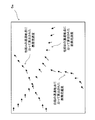
- FIG. 16 is a diagram illustrating an example of a distribution map of the wide-area surface layer velocity displayed on the display unit 5a of the present modification.
- the surface flow velocity calculated at each point where another ship passes in a predetermined sea area is displayed on the display unit 5 a of this modification.
- the direction of the arrow displayed on the screen indicates the direction of the surface flow
- the size of the arrow indicates the speed of the surface flow.
- the surface flow estimation device 1f it is possible to know not only the surface flow velocity in the vicinity of the ship position but also the surface flow velocity at a point where the ship does not pass. And by obtaining a wide-area surface flow distribution in this way, it is possible to know the surface layer flow at the point where the ship is expected to pass in the future, as useful information in predicting the arrival time to the target point and calculating fuel consumption Can be used.
- FIG. 17 is a block diagram showing a configuration of a surface layer flow estimation apparatus 1g according to a modification.
- the surface flow estimation device 1g according to the present modification includes an other ship calculation unit 18 that calculates the surface layer flow velocity of another ship. This is different from the surface layer flow estimation apparatus 1f shown in FIG.
- the other ship information receiving unit 17a acquires the propeller rotation speed, wind direction and wind speed information, position information, and the like of the other ship as needed. And the other ship calculating part 18 calculates the surface layer flow velocity in the point which the other ship passed based on these information.
- the surface layer flow velocity vector at the passage point of the other ship calculated in this way is displayed on the display unit 5a together with the surface layer flow velocity vector at the point where the ship has passed (see FIG. 16).
- FIG. 18 is a block diagram showing a configuration of the surface layer flow estimation apparatus 1h according to the modification.
- the GPS signal receiving unit 2 and the like constituting a part of the surface layer flow estimation device 1h and the calculation unit 10h are mounted at different locations.
- the GPS signal receiving unit 2, the propeller rotation number detecting unit 3, and the wind direction anemometer 4 are mounted on the ship, and the calculation unit 10h is, for example, data installed on land.
- the center 30 is provided.
- the surface layer flow estimation apparatus 1h which concerns on this modification is provided with the transmission part 19a and the receiving part 19b which were mounted in the own ship.
- the transmission unit 19a transmits various data detected by the GPS signal reception unit 2, the propeller rotation number detection unit 3, and the anemometer 4 to the data center 30 via the antenna.
- the calculation unit 10h of the data center 30 calculates the surface layer flow velocity based on the various data as in the case of the above embodiment.
- the calculation unit 10 h calculates the surface layer flow velocity at each point where the ship has passed, and stores these in the database unit 31.
- the receiving unit 19b receives the surface layer flow velocity data stored in the database unit 31. This data is displayed on the display unit 5.
- a calculation unit having a relatively large calculation load can be provided in a place different from the own ship. Thereby, even if it does not mount a calculating part in own ship, the surface layer flow velocity in the own ship position can be estimated.
- the information on other ships is collected in the data center 30, and the surface layer flow velocity at the position of other ships is also calculated based on these information, thereby obtaining the wide-area surface layer flow distribution (see FIG. 19). .
- the learning data can be supplemented when the learning data is not sufficiently accumulated.
- FIG. 20 is a schematic diagram for explaining complementation of learning data. Since the shape of the ship is generally bilaterally symmetric, it is expected that the wind power characteristics (the traveling speed of the ship due to the wind direction and wind speed) are also bilaterally symmetric. Specifically, for example, a ship that is sailing under certain conditions receives 45 degrees of wind behind the starboard and 45 degrees of wind behind the starboard (the wind speed is the same). Then, the traveling direction is expected to be symmetrical.
- the propeller speed is a predetermined speed
- wind direction port backward 45 degrees when the wind speed is a predetermined magnitude, of the ground speed was V G
- the learned Based on the data the data can be supplemented as follows.
- the size of the propeller speed and the wind speed is the same as the learning data, it is possible to wind direction starboard aft 45 degrees, as learning data when the complements the vector V 'G obtained by mirror-inverting .
- the surface layer flow can be accurately estimated even in the initial stage where the learning data is not sufficiently accumulated, for example.
- FIG. 21 is a block diagram showing an example of the ocean model estimation device 35.
- the ocean model estimation device 35 is a device including the surface layer flow estimation device described above, and is for estimating a surface layer flow velocity specific to each position of the ocean, that is, a position specific ocean model, according to the sea state weather information. It is.
- the ocean model estimation device 35 includes a second estimator 36 and a coupling coefficient update unit 37 in addition to the surface layer flow estimation device described above.
- the second estimator 36 is configured using a neural network. And the 2nd estimator 36 is comprised so that the surface layer flow velocity according to the input positional information and sea state weather information may be output as an output value.
- sea state information a tide level, atmospheric pressure, seawater temperature, etc. are mentioned, for example.
- the coupling coefficient updating unit 37 compares the surface layer flow velocity calculated by the surface layer flow calculating unit 13 with the output value estimated by the second estimator, so that the error is reduced. Update the coupling coefficient of.
- the ocean model estimation device 35 since the sea state weather information is used as an input value, it is possible to know the surface flow velocity specific to the position according to the sea state and weather. Then, for example, ocean models around the world can be constructed by calculating the surface current velocity specific to the position at each point on the sea and accumulating it as data.
- FIG. 22 is a block diagram showing an example of the configuration of the risk determination device 40.
- the degree-of-risk determination apparatus 40 is an apparatus provided with the above-described surface layer flow estimation apparatus, and is for determining the degree of risk of waves for the ship.
- the risk determination device 40 includes a spectrum decomposition unit 41 and a risk determination unit 42 in addition to the above-described surface layer flow estimation device.
- the ground speed calculation unit 11 calculates the ground speed in the three axial directions (horizontal plane direction and vertical direction), and the estimator 12 calculates the water speed in the three axial directions. To do. Thereby, the surface layer flow calculation unit 13 calculates the surface layer flow velocity including the wave component.
- the spectrum decomposition unit 41 decomposes the surface layer flow velocity including the wave component calculated by the surface layer flow calculation unit 13 into a DC component (DC component) and an AC component (AC component).
- the spectrum decomposing unit 41 outputs these to the risk determining unit 42.
- the risk determination unit 42 comprehensively determines each output value from the spectrum decomposition unit 41, and determines the wave risk level for the ship. Specifically, for example, as an example, the risk determination unit 42 determines that the risk is low when the DC component and the AC component are relatively small, and the risk is high when the DC component and the AC component are large. Is determined. The determination result is output to the display unit 5b.
- the GPS signal receiving unit 2 mounted on a general ship is used without newly installing a device such as a transducer on the bottom of the ship. Based on the obtained sea surface condition, it is possible to know the degree of wave danger to the ship.
- the roll of the ship (swaying from side to side with respect to the longitudinal direction of the ship), the pitch (swaying from side to side with respect to the horizontal direction of the ship), etc.
- the risk level may be determined with reference to the reference.
Landscapes
- Engineering & Computer Science (AREA)
- Aviation & Aerospace Engineering (AREA)
- Physics & Mathematics (AREA)
- General Physics & Mathematics (AREA)
- Life Sciences & Earth Sciences (AREA)
- Atmospheric Sciences (AREA)
- Environmental & Geological Engineering (AREA)
- Chemical & Material Sciences (AREA)
- Combustion & Propulsion (AREA)
- Mechanical Engineering (AREA)
- Ocean & Marine Engineering (AREA)
- Indicating Or Recording The Presence, Absence, Or Direction Of Movement (AREA)
Abstract
Description
を備えている。
件に対応する複数の前記対地速度ベクトルの平均値を前記出力値として出力するように、構成されている。
前記受信部は、前記演算部によって算出された、前記他船が位置する地点における前記表層流速度ベクトル、も受信する。
されるとともに、該領域における前記自船の前記対象地点での前記表層流速度ベクトルと、該領域における前記他船が位置する地点での前記表層流速度ベクトルと、を表示可能な表示部、を更に備えている。
図1は、本発明の実施形態に係る表層流推定装置1の構成を示すブロック図である。表層流推定装置1は、図1に示すように、GPS信号受信部2と、プロペラ回転数検出部3と、風向風速計4と、演算部10と、表示部5と、を備えている。
た時刻とともに、演算部10に通知される。
隠れ層の各中間ユニットUMID_1,UMID_2,UMID_3は、入力された各値を合計し、その合計値に基づく値に結合係数WM,Oを乗算して出力ユニットUOUT_1,UOUT_2に出力する。出力ユニットUOUT_1,UOUT_2は、入力された各値を合計し、その合計値に基づく値を出力値として、表層流算出部13及び結合係数更新部14に出力する。なお、上記推定器12に入力される値は、必ずしも、プロペラ回転数等、パラメータの値そのもののでなくてもよく、それらのパラメータと一対一の関係にある数値(例えば一例として、回転数と比例して変化する電圧値)等であってもよい。
図4は、推定器12から出力される出力値が、該推定器12の結合係数Wが更新される毎に、対水速度に収束していく理由を説明するための図である。上述のように、推定器12に記憶される各結合係数Wは、推定器12から随時出力される値と、随時算出される教師信号としての対地速度との誤差が小さくなるように、結合係数更新部14によって更新される。
響が徐々に小さくなるため、推定器12の出力値は、対水速度に収束していく。従って、学習が十分進んだ段階においては(すなわち、結合係数が十分な回数、更新された段階においては)、推定器12からの出力値を、対水速度と推定することができる。
以上のように、本実施形態に係る表層流推定装置1では、対地速度算出部11で算出された対地速度、及び推定器12によって推定された対水速度に基づいて、表層流を算出している。これにより、船舶の移動に比較的大きな影響を与える海面付近の表層流を、比較的容易に推定することができる。
(1)図5は、変形例に係る表層流推定装置1aの構成を示すブロック図である。本変形例に係る表層流推定装置1aは、図1に示す表層流推定装置1と異なり、結合係数更新部14が省略された構成となっている。すなわち、本変形例に係る表層流推定装置1aは、学習機能を有さない。
つ回転数の値がR1のときに算出された対地速度の値が、5つ、記憶されている。
ΔWi,j n,n-1(t)=ηδi nXj n-1+αΔWi,j n,n-1(t-1)…(1)
mi(t+1)=mi(t)+hi(t)[x(t)-mi(t)]…(2)
過した地点のそれぞれで算出された表層流速度が表示される。図16に示す例では、画面に表示される矢印の向きが表層流の向きを示し、矢印の大きさが表層流の速さを示している。
とでは、その進行方向が左右対称になると予想される。よって、図20を参照して、例えば、プロペラ回転数が所定の回転数、風向が左舷後方45度、風速が所定の大きさ、のときに、対地速度がVGであった場合、その学習データに基づいて、以下のようにデータを補完することができる。具体的には、プロペラ回転数及び風速の大きさは上記学習データと同じであり、風向が右舷後方45度、のときの学習データとして、左右反転させたベクトルV'Gを補完することができる。このように学習データを補完することにより、例えば学習データの蓄積が不十分な初期段階であっても、精度よく表層流を推定することができる。
11 対地速度算出部
12,12a,12b,…12e 推定器
13 表層流算出部
Claims (14)
- 海上において船舶が位置する対象地点における表層流の速度ベクトルである表層流速度ベクトルを推定する表層流推定装置であって、
前記対象地点における前記船舶の対地速度ベクトルを算出する対地速度算出部と、
前記船舶の対水速度ベクトルに影響を与える少なくとも1つのパラメータの、前記対象地点における値の入力を受け付けるとともに、受け付けられた各前記値の組み合わせにより特定される各条件に対応する値を、前記船舶の前記対水速度ベクトルと推定して出力する推定器と、
前記推定器で推定された前記対水速度ベクトルとしての出力値と、前記対地速度算出部で算出された前記対地速度ベクトルとに基づき、前記対象地点における前記表層流速度ベクトルを算出する表層流算出部と、
を備えていることを特徴とする、表層流推定装置。 - 請求項1に記載の表層流推定装置において、
前記推定器は、ニューラルネットワークを用いて、又は、前記各条件に対応する複数の前記対地速度ベクトルの平均値を前記出力値として出力するように、構成されていることを特徴とする、表層流推定装置。 - 請求項1又は請求項2に記載の表層流推定装置において、
前記推定器からの前記出力値と、前記対地速度算出部で算出された前記対地速度ベクトルとを比較するとともに、該出力値と該対地速度ベクトルとの誤差が少なくなるように、前記推定器を更新する更新部、
を更に備えていることを特徴とする、表層流推定装置。 - 請求項3に記載の表層流推定装置において、
前記推定器は、ニューラルネットワークを用いて構成され、
それぞれに、前記少なくとも1つのパラメータのうちのいずれか1つが入力される少なくとも1つの入力ユニットと、
前記対水速度ベクトルとしての前記出力値を出力する出力ユニットと
を有し、
前記ニューラルネットワークにおける入力側のユニットから出力される値には、結合係数が乗算された後、出力側のユニットに伝送され、
前記更新部は、前記出力値と、教師信号としての前記対地速度ベクトルとを比較するとともに、該出力値と該教師信号との誤差が少なくなるように、前記結合係数を更新することを特徴とする、表層流推定装置。 - 請求項1から請求項4のいずれか1項に記載の表層流推定装置において、
前記表層流算出部は、前記対地速度算出部で算出された前記対地速度ベクトルから、前記推定器で推定された前記対水速度ベクトルを減算することにより、前記表層流速度ベクトルを算出することを特徴とする、表層流推定装置。 - 請求項1から請求項5のいずれか1項に記載の表層流推定装置において、
前記船舶に搭載され、GNSS信号を受信するGNSS信号受信部を更に備え、
前記対地速度算出部は、前記GNSS信号受信部で受信されたGNSS信号、及び該GNSS信号が受信された時刻に基づき、前記対地速度ベクトルを算出することを特徴とする、表層流推定装置。 - 請求項1から請求項6のいずれか1項に記載の表層流推定装置において、
前記パラメータは、前記船舶のプロペラの回転数、風向及び風速に関する情報、前記船
舶の舵角、前記船舶の喫水、波に関する情報、前記船舶のロール角、前記船舶のピッチ角、前記船舶のヒーブの量、海況に関する情報、気象に関する情報、又は位置情報、であることを特徴とする、表層流推定装置。 - 請求項7に記載の表層流推定装置において、
前記プロペラの回転数を検出するプロペラ回転数検出部と、
前記船舶に搭載される風速風向計と、を更に備え、
前記推定器には、少なくとも、前記プロペラ回転数検出部で検出された前記プロペラの回転数と、前記風速風向計で計測された前記風向及び風速に関する情報と、が入力されることを特徴とする、表層流推定装置。 - 請求項1から請求項8のいずれか1項に記載の表層流推定装置において、
前記船舶としての自船に搭載されていることを特徴とする、表層流推定装置。 - 前記船舶としての自船とは異なる場所に搭載された、請求項1から請求項8のいずれか1項に記載の表層流推定装置の対地速度算出部、推定器、及び表層流算出部を有する演算部と、
前記自船に搭載され、該自船の前記対水速度ベクトルに影響を与える前記少なくとも1つのパラメータの値を前記演算部に送信する送信部と、
前記自船に搭載され、前記演算部で算出された前記対象地点における前記表層流速度ベクトルを受信する受信部と、
を備えていることを特徴とする、表層流推定システム。 - 請求項10に記載の表層流推定システムにおいて、
前記演算部は、他船における前記少なくとも1つのパラメータの値に基づいて、該他船が位置する地点における前記表層流速度ベクトルも算出し、
前記受信部は、前記演算部によって算出された、前記他船が位置する地点における前記表層流速度ベクトル、も受信することを特徴とする、表層流推定システム。 - 請求項11に記載の表層流推定システムにおいて、
海上における所望の領域が表示されるとともに、該領域における前記自船の前記対象地点での前記表層流速度ベクトルと、該領域における前記他船が位置する地点での前記表層流速度ベクトルと、を表示可能な表示部、を更に備えていることを特徴とする、表層流推定システム。 - 請求項1から請求項9のいずれか1項に記載の表層流推定装置、又は、請求項10若しくは請求項11に記載の表層流推定システムを備え、
前記表層流推定装置又は前記表層流推定システムの推定器は、第1推定器として設けられ、
ニューラルネットワークを用いて構成され、自船の位置情報、及び現在の海況気象情報、を受け付けるとともに、受け付けられた各前記情報の組み合わせにより特定される各条件に対応する値を出力値として出力するとともに、前記表層流推定装置又は前記表層流推定システムで算出された教師信号としての表層流速度ベクトルと前記出力値との誤差が少なくなるように更新される第2推定器、を更に備えていることを特徴とする、海洋モデル推定装置。 - 請求項1から請求項9のいずれか1項に記載の表層流推定装置、又は、請求項10若しくは請求項11に記載の表層流推定システムと、
少なくとも、前記表層流推定装置又は前記表層流推定システムで推定された表層流速度ベクトルに基づいて、自船に対する波の危険度を判定する判定部と、
を備えていることを特徴とする、危険度判定装置。
Priority Applications (2)
| Application Number | Priority Date | Filing Date | Title |
|---|---|---|---|
| JP2016505097A JP6340067B2 (ja) | 2014-02-25 | 2015-01-20 | 表層流推定装置、表層流推定システム、海洋モデル推定装置、及び危険度判定装置 |
| EP15754998.1A EP3112877B1 (en) | 2014-02-25 | 2015-01-20 | Surface current estimation device, surface current estimation system, ocean model estimation device, and risk determination device |
Applications Claiming Priority (2)
| Application Number | Priority Date | Filing Date | Title |
|---|---|---|---|
| JP2014-034478 | 2014-02-25 | ||
| JP2014034478 | 2014-02-25 |
Publications (1)
| Publication Number | Publication Date |
|---|---|
| WO2015129337A1 true WO2015129337A1 (ja) | 2015-09-03 |
Family
ID=54008666
Family Applications (1)
| Application Number | Title | Priority Date | Filing Date |
|---|---|---|---|
| PCT/JP2015/051301 Ceased WO2015129337A1 (ja) | 2014-02-25 | 2015-01-20 | 表層流推定装置、表層流推定システム、海洋モデル推定装置、及び危険度判定装置 |
Country Status (3)
| Country | Link |
|---|---|
| EP (1) | EP3112877B1 (ja) |
| JP (1) | JP6340067B2 (ja) |
| WO (1) | WO2015129337A1 (ja) |
Cited By (6)
| Publication number | Priority date | Publication date | Assignee | Title |
|---|---|---|---|---|
| WO2018029397A1 (en) | 2016-08-09 | 2018-02-15 | Eniram Oy | A method and a system for optimising operation of a vessel |
| CN111220813A (zh) * | 2020-01-13 | 2020-06-02 | 广州船舶及海洋工程设计研究院(中国船舶工业集团公司第六0五研究院) | 船舶的航速确定方法、续航里程确定方法、装置和系统 |
| KR102631383B1 (ko) * | 2023-04-21 | 2024-01-31 | 주식회사 테렌즈 | 인공지능 기반 선박 운항 변수 예측 방법 및 상기 방법이 기록된 컴퓨터 판독 가능한 기록매체 |
| JP7489150B1 (ja) | 2023-11-30 | 2024-05-23 | 陽一 金子 | 風速計、風速計算方法、及び、プログラム |
| US12208869B2 (en) | 2022-06-15 | 2025-01-28 | Furuno Electric Co., Ltd. | Disturbance estimating apparatus, method, and computer program |
| US12461495B2 (en) | 2022-05-17 | 2025-11-04 | Furuno Electric Co., Ltd. | Disturbance estimating apparatus, method, and computer program |
Citations (5)
| Publication number | Priority date | Publication date | Assignee | Title |
|---|---|---|---|---|
| JPS61159107A (ja) * | 1984-12-29 | 1986-07-18 | Japan Radio Co Ltd | 船舶用受信装置 |
| JPH11237477A (ja) * | 1998-02-20 | 1999-08-31 | Nagano Japan Radio Co | 短波または超短波を用いた海洋レーダおよび短波または超短波を用いた海洋レーダシステム |
| JP2004226374A (ja) * | 2003-01-27 | 2004-08-12 | Tech Res & Dev Inst Of Japan Def Agency | 位置計測システム、位置計測方法、プログラム及び航走体運用システム |
| JP2004233185A (ja) * | 2003-01-30 | 2004-08-19 | Yokogawa Electric Corp | 高機能gpsとそれを用いた航法装置 |
| JP2011214471A (ja) * | 2010-03-31 | 2011-10-27 | Mitsui Eng & Shipbuild Co Ltd | 船舶の主機制御システムおよび方法 |
Family Cites Families (8)
| Publication number | Priority date | Publication date | Assignee | Title |
|---|---|---|---|---|
| JP2001264437A (ja) * | 2000-03-22 | 2001-09-26 | Furuno Electric Co Ltd | 潮流分布測定システム、潮流分布測定装置、潮流分布測定方法、水中探知システム |
| JP3949932B2 (ja) * | 2001-10-30 | 2007-07-25 | 三井造船株式会社 | 自律型水中航走体の航走制御装置 |
| JP2003344437A (ja) * | 2002-05-27 | 2003-12-03 | Yamaha Motor Co Ltd | 対地速度算出方法及び対地速度算出装置 |
| KR100868849B1 (ko) * | 2007-01-30 | 2008-11-14 | 현대중공업 주식회사 | 선박의 속력 시운전 최적코스 선정 방법 |
| JP5191263B2 (ja) * | 2008-04-07 | 2013-05-08 | 日本郵船株式会社 | 船舶の航行状態分析装置 |
| IL192518A (en) * | 2008-06-30 | 2013-02-28 | Michael Naumov | Method and device for the autonomous determination of wind speed vector |
| JP2011210551A (ja) * | 2010-03-30 | 2011-10-20 | Nec Lighting Ltd | 照明器具のグローブ、照明器具用フィルターおよび照明器具 |
| JP6036515B2 (ja) * | 2013-04-22 | 2016-11-30 | 株式会社Ihi | 水中航走体 |
-
2015
- 2015-01-20 EP EP15754998.1A patent/EP3112877B1/en active Active
- 2015-01-20 WO PCT/JP2015/051301 patent/WO2015129337A1/ja not_active Ceased
- 2015-01-20 JP JP2016505097A patent/JP6340067B2/ja not_active Expired - Fee Related
Patent Citations (5)
| Publication number | Priority date | Publication date | Assignee | Title |
|---|---|---|---|---|
| JPS61159107A (ja) * | 1984-12-29 | 1986-07-18 | Japan Radio Co Ltd | 船舶用受信装置 |
| JPH11237477A (ja) * | 1998-02-20 | 1999-08-31 | Nagano Japan Radio Co | 短波または超短波を用いた海洋レーダおよび短波または超短波を用いた海洋レーダシステム |
| JP2004226374A (ja) * | 2003-01-27 | 2004-08-12 | Tech Res & Dev Inst Of Japan Def Agency | 位置計測システム、位置計測方法、プログラム及び航走体運用システム |
| JP2004233185A (ja) * | 2003-01-30 | 2004-08-19 | Yokogawa Electric Corp | 高機能gpsとそれを用いた航法装置 |
| JP2011214471A (ja) * | 2010-03-31 | 2011-10-27 | Mitsui Eng & Shipbuild Co Ltd | 船舶の主機制御システムおよび方法 |
Cited By (11)
| Publication number | Priority date | Publication date | Assignee | Title |
|---|---|---|---|---|
| WO2018029397A1 (en) | 2016-08-09 | 2018-02-15 | Eniram Oy | A method and a system for optimising operation of a vessel |
| JP2019532262A (ja) * | 2016-08-09 | 2019-11-07 | エニラム オサケユキチュア | 船舶運航を最適化するための方法及びシステム |
| US10501162B2 (en) | 2016-08-09 | 2019-12-10 | Eniram Oy | Method and system for optimising operation of vessel |
| US11292570B2 (en) | 2016-08-09 | 2022-04-05 | Wartsila Finland Oy | Method and system for optimizing operation of vessel |
| CN111220813A (zh) * | 2020-01-13 | 2020-06-02 | 广州船舶及海洋工程设计研究院(中国船舶工业集团公司第六0五研究院) | 船舶的航速确定方法、续航里程确定方法、装置和系统 |
| CN111220813B (zh) * | 2020-01-13 | 2022-01-11 | 广州船舶及海洋工程设计研究院(中国船舶工业集团公司第六0五研究院) | 船舶的航速确定方法、续航里程确定方法、装置和系统 |
| US12461495B2 (en) | 2022-05-17 | 2025-11-04 | Furuno Electric Co., Ltd. | Disturbance estimating apparatus, method, and computer program |
| US12208869B2 (en) | 2022-06-15 | 2025-01-28 | Furuno Electric Co., Ltd. | Disturbance estimating apparatus, method, and computer program |
| KR102631383B1 (ko) * | 2023-04-21 | 2024-01-31 | 주식회사 테렌즈 | 인공지능 기반 선박 운항 변수 예측 방법 및 상기 방법이 기록된 컴퓨터 판독 가능한 기록매체 |
| JP7489150B1 (ja) | 2023-11-30 | 2024-05-23 | 陽一 金子 | 風速計、風速計算方法、及び、プログラム |
| JP2025088265A (ja) * | 2023-11-30 | 2025-06-11 | 陽一 金子 | 風速計、風速計算方法、及び、プログラム |
Also Published As
| Publication number | Publication date |
|---|---|
| JPWO2015129337A1 (ja) | 2017-03-30 |
| EP3112877B1 (en) | 2018-07-18 |
| EP3112877A1 (en) | 2017-01-04 |
| JP6340067B2 (ja) | 2018-06-06 |
| EP3112877A4 (en) | 2017-08-02 |
Similar Documents
| Publication | Publication Date | Title |
|---|---|---|
| JP6513677B2 (ja) | 船舶特性推定装置、及び自動操舵装置 | |
| JP6340067B2 (ja) | 表層流推定装置、表層流推定システム、海洋モデル推定装置、及び危険度判定装置 | |
| Thomson | Wave breaking dissipation observed with “SWIFT” drifters | |
| US9262874B2 (en) | Real-time performance models for vessels | |
| JP5312425B2 (ja) | 船舶運航支援システム | |
| KR101275277B1 (ko) | 사각단위항로 생성기법을 이용한 가항항로내 선박 피항 항로 탐색 지원 시스템 | |
| GB2474715A (en) | Aiding navigation of a marine vessel in a tidal region | |
| CN109562819B (zh) | 用于确定海船的对水速度的方法和传感器系统 | |
| JP6132990B2 (ja) | 状態推定装置 | |
| Wadhams et al. | Sidescan sonar imagery of the winter marginal ice zone obtained from an AUV | |
| Moulton et al. | Improving the time resolution of surfzone bathymetry using in situ altimeters | |
| MX2013008599A (es) | Metodo para dirigir una antena lineal acustica remolcada. | |
| Brown et al. | The use of autonomous vehicles for spatially measuring mean velocity profiles in rivers and estuaries | |
| WO2019004362A1 (ja) | 船舶の運航支援装置及び運航支援プログラム | |
| WO2016098491A1 (ja) | 最適回転数推定装置、最適回転数推定システム、及び回転数制御装置 | |
| JP6154540B2 (ja) | 船舶特性推定装置 | |
| Worst et al. | A comparison of vessel-mounted acoustic Doppler current profiler and satellite altimeter estimates of sea surface height and transports between New Jersey and Bermuda along the CMV Oleander route | |
| Boltryk et al. | An ultrasonic transducer array for velocity measurement in underwater vehicles | |
| US20240004062A1 (en) | Geographically augmented sonar | |
| Stanway | Dead reckoning through the water column with an acoustic Doppler current profiler: Field experiences | |
| JP7652618B2 (ja) | 物体検出装置、物体検出方法および物体検出プログラム | |
| Li et al. | Measurements of a small scale eddy at a tidal inlet using an unmanned automated boat | |
| de Campos Carvalho et al. | Proper environmental reduction for attenuation in multi-sector sonars | |
| Henley et al. | Performance of 3D forward looking sonar for bathymetric survey | |
| Shi et al. | Experimental setup and investigation of deep-sea navigation and positioning network |
Legal Events
| Date | Code | Title | Description |
|---|---|---|---|
| 121 | Ep: the epo has been informed by wipo that ep was designated in this application |
Ref document number: 15754998 Country of ref document: EP Kind code of ref document: A1 |
|
| ENP | Entry into the national phase |
Ref document number: 2016505097 Country of ref document: JP Kind code of ref document: A |
|
| REEP | Request for entry into the european phase |
Ref document number: 2015754998 Country of ref document: EP |
|
| WWE | Wipo information: entry into national phase |
Ref document number: 2015754998 Country of ref document: EP |
|
| NENP | Non-entry into the national phase |
Ref country code: DE |