WO2015129305A1 - 携帯端末装置 - Google Patents
携帯端末装置 Download PDFInfo
- Publication number
- WO2015129305A1 WO2015129305A1 PCT/JP2015/050608 JP2015050608W WO2015129305A1 WO 2015129305 A1 WO2015129305 A1 WO 2015129305A1 JP 2015050608 W JP2015050608 W JP 2015050608W WO 2015129305 A1 WO2015129305 A1 WO 2015129305A1
- Authority
- WO
- WIPO (PCT)
- Prior art keywords
- mobile terminal
- communication
- base station
- terminal device
- terminal
- Prior art date
- Legal status (The legal status is an assumption and is not a legal conclusion. Google has not performed a legal analysis and makes no representation as to the accuracy of the status listed.)
- Ceased
Links
Images




Classifications
-
- H—ELECTRICITY
- H04—ELECTRIC COMMUNICATION TECHNIQUE
- H04W—WIRELESS COMMUNICATION NETWORKS
- H04W52/00—Power management, e.g. Transmission Power Control [TPC] or power classes
- H04W52/02—Power saving arrangements
- H04W52/0209—Power saving arrangements in terminal devices
- H04W52/0225—Power saving arrangements in terminal devices using monitoring of external events, e.g. the presence of a signal
- H04W52/0241—Power saving arrangements in terminal devices using monitoring of external events, e.g. the presence of a signal where no transmission is received, e.g. out of range of the transmitter
-
- H—ELECTRICITY
- H04—ELECTRIC COMMUNICATION TECHNIQUE
- H04W—WIRELESS COMMUNICATION NETWORKS
- H04W8/00—Network data management
- H04W8/005—Discovery of network devices, e.g. terminals
-
- Y—GENERAL TAGGING OF NEW TECHNOLOGICAL DEVELOPMENTS; GENERAL TAGGING OF CROSS-SECTIONAL TECHNOLOGIES SPANNING OVER SEVERAL SECTIONS OF THE IPC; TECHNICAL SUBJECTS COVERED BY FORMER USPC CROSS-REFERENCE ART COLLECTIONS [XRACs] AND DIGESTS
- Y02—TECHNOLOGIES OR APPLICATIONS FOR MITIGATION OR ADAPTATION AGAINST CLIMATE CHANGE
- Y02D—CLIMATE CHANGE MITIGATION TECHNOLOGIES IN INFORMATION AND COMMUNICATION TECHNOLOGIES [ICT], I.E. INFORMATION AND COMMUNICATION TECHNOLOGIES AIMING AT THE REDUCTION OF THEIR OWN ENERGY USE
- Y02D30/00—Reducing energy consumption in communication networks
- Y02D30/70—Reducing energy consumption in communication networks in wireless communication networks
Definitions
- the present invention relates to a mobile terminal device, and more particularly to a mobile terminal device that can use an inter-terminal communication mode for communicating with other mobile terminal devices without going through a base station.
- a mobile terminal device such as a mobile phone communicates with a communication partner such as a server and other mobile terminal devices via a base station and a wireless communication network. For this reason, if a large-scale disaster such as an earthquake or flood occurs and communication between the base station and the wireless communication network becomes impossible, the mobile terminal device cannot communicate with the communication partner.
- D2D Device-to-Device
- Patent Document 1 discloses a mobile communication terminal having a mobile phone function and a multi-hop communication function.
- the mobile communication terminal activates a tuner that receives a radio broadcast or a television broadcast based on the information included in the control signal transmitted from the base station, detects the occurrence of the disaster in the received emergency alert broadcast, and In response to the detection, the multi-hop communication function is activated, and the multi-hop communication function permits access to a specific partner through the ad hoc network, and transmits or receives voice or data.
- the present invention has been made to solve the above-described problems, and it is an object of the present invention to provide a mobile terminal device capable of efficiently performing communication between terminals without using a base station. .
- a mobile terminal device that can use an inter-terminal communication mode that communicates with another mobile terminal device without using a base station.
- the mobile terminal device includes first receiving information for instructing communication with another mobile terminal device to perform communication in the inter-terminal communication mode, and a receiving unit that receives communication area information of another base station from the base station, A terminal search unit that searches for one or more other mobile terminal devices that can communicate with the terminal device in the inter-terminal communication mode, and one or more other mobile terminal devices that are searched by the terminal search unit. Based on the position receiving unit that receives the position information of the device and the position information and the communication area information, it is determined whether or not one or more other mobile terminal devices that have been found exist in the communication area of another base station. And a terminal communication unit that communicates with one or more other mobile terminal devices that have been searched. The terminal communication unit performs communication with the other mobile terminal device in the inter-terminal communication mode when one or more other mobile terminal devices found exist in the communication area of another base station.
- the mobile terminal device may be another information communication device such as a tablet terminal device, a notebook PC (personal computer), a PND (Personal Navigation Device), or a PDA (Personal Data Assistance).
- a tablet terminal device a notebook PC (personal computer), a PND (Personal Navigation Device), or a PDA (Personal Data Assistance).
- FIG. 1 is a schematic diagram showing an overall configuration of a communication system 1 according to the first embodiment.
- communication system 1 includes a plurality of base stations 101 and 201, mobile terminal apparatuses 11 to 17, 21 and 22, and a base station monitoring apparatus 301.
- the base stations 101 and 201 execute an operation according to LTE (Long Term Evolution) in a radio communication access technology (RAT) standardized in 3GPP (Third Generation Partnership Project).
- LTE Long Term Evolution
- RAT radio communication access technology
- the base station 101 is unusable due to the occurrence of a disaster.
- the base station 201 constitutes a communication area (cell) 2000.
- Communication area 1000 is a communication area of base station 101 when base station 101 is in a usable state.
- the mobile terminal devices 11 to 17, 21, and 22 are UEs (User Equipment) that perform wireless communication in accordance with a radio access technology such as LTE. These portable terminal devices communicate directly with other portable terminal devices without going through the base station, and with the normal communication mode that communicates with other portable terminal devices through the base station as operation modes using LTE communication.
- the terminal-to-terminal communication (D2D communication) mode can be used.
- the mobile terminal devices 11 to 17 exist in the communication area 1000, but the base station 101 is in an unusable state, so communication in the normal communication mode (normal communication) is not possible. Only communication in communication mode (communication between terminals) is possible. On the other hand, since the mobile terminal devices 21 and 22 exist in the communication area 2000 configured by the base station 201 in a usable state, normal communication and inter-terminal communication are possible.
- the base station monitoring apparatus 301 is configured to be able to communicate with the base stations 101 and 201 via the wired communication network 500.
- the base station monitoring apparatus 301 monitors whether the base stations 101 and 201 are operating normally. Specifically, when the base station monitoring device 301 receives disaster information such as an earthquake early warning distributed from the Japan Meteorological Agency, it makes a status check request to the base stations 101 and 201, and the base stations 101 and 201 operate normally. Check whether or not
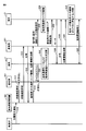
- FIG. 2 is a sequence diagram showing an outline of operation of communication system 1 according to the first embodiment.
- the base station 101 is unusable due to a disaster.
- the base station 201 in a usable state periodically receives the position information of the mobile terminal device from each of the mobile terminal devices 21 and 22 existing in the communication area 2000, and the mobile terminal device 21 , 22 are grasped.
- base station monitoring apparatus 301 receives a disaster occurrence notification such as an emergency earthquake bulletin from the Japan Meteorological Agency (step S10).
- the base station monitoring apparatus 301 transmits a status confirmation request to the base station 101 (step S12).
- the state confirmation request is a request for confirming whether or not the base station is in a usable state (a communicable state). Since the base station 101 is in an unusable state, it cannot respond to the request. Therefore, the base station monitoring apparatus 301 determines that the base station 101 is in an unusable state.
- the base station monitoring apparatus 301 transmits a status confirmation request to the base station 201 (step S14). Since the base station 201 is in a usable state, the base station 201 transmits a state confirmation response to the base station monitoring apparatus 301 (step S16). Specifically, the base station 201 transmits a response signal indicating that the base station 201 can be used to the base station monitoring apparatus 301. Note that the base station monitoring apparatus 301 may perform the processes of step S12 and step S14 in parallel.
- the base station monitoring apparatus 301 When the base station monitoring apparatus 301 receives the state confirmation response from the base station 201, the base station monitoring apparatus 301 transmits the communication area information and position information of the base station 101 which is in an unusable state to the base station 201 (step S18).
- the mobile terminal device 11 (“terminal 11” in FIG. 2) performs a channel scan in the normal communication mode (step S20). Specifically, the mobile terminal device 11 searches for a base station by trying to receive a signal transmitted from the base station while changing the communication channel, and searches for the base station. In the communication system 1, since the base station 101 is in an unusable state, the mobile terminal device 11 cannot receive a response signal from the base station 101.
- the mobile terminal device 11 switches from the normal communication mode to the inter-terminal communication mode, and searches for other mobile terminal devices capable of inter-terminal communication. Specifically, the mobile terminal device 11 transmits a search request signal to one or more other mobile terminal devices.
- the mobile terminal device 11 switches from the inter-terminal communication mode to the normal communication mode, and Run the scan again. As described above, the mobile terminal device 11 tries to communicate with another mobile terminal device while alternately switching between the normal communication mode and the inter-terminal communication mode (step S22).
- the base station 201 receives the communication area information and position information of the base station 101 from the base station monitoring device 301, the mobile terminal device 21 (FIG. 2) performs communication with other mobile terminal devices in the inter-terminal communication mode. (“Terminal 21”) in the middle (step S24). Specifically, the base station 201 is based on the communication area information of the base station 101 and the position information of the mobile terminal devices 21 and 22, and the mobile terminal device 21 is present at a position close to the communication area 1000 of the base station 101. Judgment is made and this instruction is issued to the portable terminal device 21.
- the base station 201 causes the mobile terminal device 21 to perform communication between terminals in a frequency band used in a wireless communication network under the jurisdiction of the communication carrier, so that control information for controlling the communication between terminals is transmitted to the mobile terminal. You may transmit to the apparatus 21.
- FIG. The control information includes permission information for permitting communication between terminals using a wireless communication network, and setting information of a communication environment necessary for communication between the terminals.
- the setting information includes radio resource information such as a frequency band allowed for communication between terminals, and radio field intensity of a radio signal.
- the portable terminal device 21 When the portable terminal device 21 receives the instruction, the portable terminal device 21 activates the inter-terminal communication mode (step S26). Further, the base station 201 transmits the communication area information of the base station 101 to the mobile terminal device 21 (step S28). Note that the base station 201 may be configured to further transmit the position information of the base station 101 to the mobile terminal device 21.
- the base station 201 is configured to simultaneously perform the operation instruction processing in the terminal-to-terminal communication mode in step S24 and the processing to transmit the communication area information (and location information) of the base station 101 in step S28. May be.
- the mobile terminal device 21 searches for one or more other mobile terminal devices capable of inter-terminal communication (step S30). Specifically, the mobile terminal device 21 transmits a search request signal to one or more other mobile terminal devices. The mobile terminal device 21 can uniquely identify these other mobile terminal devices based on identification information such as a telephone number and an e-mail address.
- the mobile terminal device 11 When the mobile terminal device 11 has received the request signal transmitted from the mobile terminal device 21, the mobile terminal device 11 transmits a response signal to the mobile terminal device 21 (step S32). When receiving the response signal, the mobile terminal device 21 confirms that the mobile terminal device 11 has been searched.
- the mobile terminal device 11 transmits the position information of the own device (step S34).
- the mobile terminal device 21 determines that the mobile terminal device 11 exists in the communication area 1000 of the base station 101 based on the searched location information of the mobile terminal device 11 and the communication area information of the base station 101 (Ste S36). Then, communication between terminals between the mobile terminal device 11 and the mobile terminal device 21 is established (step S38). Specifically, the mobile terminal device 11 and the mobile terminal device 21 transmit and receive various data (disaster notification information, applications, etc.) in the inter-terminal communication mode. Note that the mobile terminal device 21 may transmit the control information received from the base station 201 to the mobile terminal device 11.
- step S30 when the mobile terminal device 21 searches for the mobile terminal device 16 in addition to the mobile terminal device 11, the mobile terminal device performs the same processing as that performed with the mobile terminal device 11 described above. 16 is also performed to establish communication between the mobile terminal device 16 and the terminal.
- the mobile terminal device 11 that has established inter-terminal communication with the mobile terminal device 21 existing in the communication area 2000 further searches for another mobile terminal device capable of inter-terminal communication. Then, the mobile terminal device 11 establishes terminal-to-terminal communication with the searched mobile terminal device 12 and mobile terminal device 16. Similarly, the mobile terminal device 16 establishes inter-terminal communication with the mobile terminal devices 11, 17, and 21, and the mobile terminal device 12 establishes inter-terminal communication with the mobile terminal devices 11 and 13. The mobile terminal device 13 establishes inter-terminal communication with the mobile terminal devices 14 and 15.
- Each mobile terminal device is configured to communicate only with a predetermined number (for example, 8) of mobile terminal devices when communicating with other mobile terminal devices in the inter-terminal communication mode. It may be. Alternatively, each mobile terminal device may determine the number of mobile terminal devices that are communication partners based on the remaining battery level of the mobile device when another mobile terminal device is searched.
- FIG. 3 is a block diagram showing a hardware configuration of portable terminal device 21 according to the first embodiment.
- a mobile terminal device 21 includes, as main components, a CPU (Central Processing Unit) 102, a memory 104, a touch panel 106, a display 108, a wireless communication unit 110, a memory interface (I / I). F) 114, a communication interface (I / F) 116, a GPS (Global Positioning System) controller 118, a battery 120, and a timer 122.
- the mobile terminal devices 11 to 17 and 22 also have the same hardware configuration as the mobile terminal device 21.
- CPU102 controls the operation
- the memory 104 is realized by a RAM (Random Access Memory), a ROM (Read-Only Memory), a flash memory, or the like.
- the memory 104 stores a program executed by the CPU 102 or data used by the CPU 102.
- the touch panel 106 is provided on a display 108 having a function as a display unit, and is, for example, a capacitance type.
- the touch panel 106 detects a touch operation on the touch panel 106 by an external object every predetermined time, and inputs touch coordinates to the CPU 102.
- the wireless communication unit 110 connects to a wireless communication network via the communication antenna 112 and transmits and receives signals for wireless communication.
- the mobile terminal device 21 can execute communication with other mobile terminal devices via the base station using a wireless communication network such as LTE (Long Term Evolution), for example. It is possible to execute inter-terminal communication with other portable terminal devices without going through.
- LTE Long Term Evolution
- the memory interface (I / F) 114 reads data from the external storage medium 115.
- the CPU 102 reads data from the memory 104 and stores the data in an external storage medium 115 via the memory interface 114.
- the storage medium 115 may be a CD (Compact Disc), a DVD (Digital Versatile Disk), a BD (Blu-ray (registered trademark) Disc), a USB (Universal Serial Bus) memory, an SD (Secure Digital) memory card, or the like.
- a medium for storing the program in a nonvolatile manner can be mentioned.
- the communication interface (I / F) 116 exchanges various data with an external device, and is realized by an adapter, a connector, or the like.
- the communication method may be, for example, wireless communication using Bluetooth (registered trademark), wireless LAN (Local Area Network), or wired communication using USB (Universal Serial Bus). .
- the GPS controller 118 receives a GPS signal or a position signal (positioning signal) from the base station and acquires position information of the mobile terminal device 21.
- the GPS controller 118 inputs the acquired position information of the mobile terminal device 21 to the CPU 102.
- the battery 120 is a chargeable / dischargeable power storage element, and typically includes a secondary battery such as a lithium ion battery or a nickel metal hydride battery.
- the timer 122 measures the time and sends a signal corresponding to the measured time to the CPU 102.
- the CPU 102 performs a predetermined process based on the signal.
- the mobile terminal device 21 may include a button for receiving an instruction from the user, a microphone for receiving an utterance to the mobile terminal device 21, and a speaker for outputting sound.
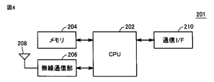
- FIG. 4 is a block diagram showing a hardware configuration of base station 201 according to the first embodiment.
- base station 201 includes, as main components, a CPU 202 for executing various processes, a memory 204 for storing programs executed by CPU 202, various data, and a wireless communication network. And a communication interface (I / F) 210 for communicating with the base station monitoring apparatus 301.
- the base station 101 has the same hardware configuration as the base station 201.
- the memory 204 In the memory 204, communication area information and position information of the base station 201 are registered (stored). Further, the CPU 202 receives the position information of the mobile terminal device transmitted from each mobile terminal device via the wireless communication unit 206 and the communication antenna 208, and stores the position information in the memory 204. Further, the CPU 202 receives communication area information and position information of other base stations transmitted from the base station monitoring apparatus 301 via the communication interface 210, and stores the communication area information and position information in the memory 204.
- FIG. 5 is a block diagram showing a hardware configuration of base station monitoring apparatus 301 according to the first embodiment.
- a base station monitoring apparatus 301 includes, as main components, a CPU 302 for executing various processes, a memory 304 for storing programs executed by the CPU 302, various data, and the like. And a communication interface (I / F) 308 for communicating with the base station.
- I / F communication interface
- the memory 304 In the memory 304, communication area information and position information of each base station are registered (stored).
- FIG. 6 is a functional block diagram of portable terminal device 21 according to the first embodiment.
- the mobile terminal devices 11 to 17 and 22 also have the same functional configuration as the mobile terminal device 21.
- mobile terminal device 21 has, as its main functional configuration, base station information reception unit 152, terminal search unit 154, terminal information reception unit 156, area determination unit 158, and terminal communication unit 160. Including. These functions are mainly realized by the CPU 102 of the mobile terminal device 21 executing a program stored in the memory 104 and giving a command to the components of the mobile terminal device 21.
- the CPU 102 has a function as a control unit that controls the entire operation of the mobile terminal device 21. Note that some or all of these functional configurations may be realized by hardware.
- the base station information receiving unit 152 receives, from the base station 201, instruction information for instructing communication with another mobile terminal device in the inter-terminal communication mode. Further, the base station information receiving unit 152 receives communication area information of other base stations from the base station 201. Specifically, the base station information receiving unit 152 receives communication area information of the base station 101 that has become unusable from the base station 201. Note that the base station information receiving unit 152 may receive position information of other base stations from the base station 201.
- the terminal search unit 154 searches for one or more other mobile terminal devices that can communicate with the mobile terminal device in the inter-terminal communication mode. Specifically, the terminal search unit 154 searches for another mobile terminal device by transmitting a search request signal to one or more other mobile terminal devices. For example, when receiving a response signal from the mobile terminal device 11, the terminal search unit 154 determines that the mobile terminal device 11 has been searched. Note that the terminal search unit 154 can search for other portable terminal devices capable of inter-terminal communication within a range where a search request signal reaches.
- the terminal information receiving unit 156 receives position information of the other mobile terminal device from one or more other mobile terminal devices searched by the terminal search unit 154. Note that the terminal information receiving unit 156 may receive identification information (such as a telephone number) from the other mobile terminal device.
- the area determination unit 158 places the searched other mobile terminal device in the communication area 1000 of the base station 101. Determine if it exists.
- the terminal communication unit 160 communicates with one or more other mobile terminal devices that are found. Specifically, the terminal communication unit 160 is configured to be able to communicate with other mobile terminal devices in either the normal communication mode or the inter-terminal communication mode. When one or more other mobile terminal devices that have been found exist in the communication area of the base station 101, the terminal communication unit 160 communicates with the other mobile terminal devices in the inter-terminal communication mode.
- the terminal communication unit 160 may change another predetermined number (for example, 8) of the other mobile terminal devices. Communication is performed with the mobile terminal device in the inter-terminal communication mode. For example, the terminal communication unit 160 communicates with the upper eight mobile terminal devices in the searched order in the inter-terminal communication mode. In addition, the terminal communication unit 160 communicates with the top eight mobile terminal devices in the order of the position of the own device based on the position information of the own device and the position information of a plurality of other mobile terminal devices in the inter-terminal communication mode May be performed. Note that the number is stored in the memory 104.
- the remaining amount detection unit 162 detects the remaining amount of the battery 120 of the mobile terminal device 21.
- the memory 204 stores a terminal number table 600 in which the range of the remaining battery level of the mobile terminal device 21 is associated with the number of other mobile terminal devices that are communication partners in the inter-terminal communication mode. .
- FIG. 7 is a diagram showing a terminal number table 600 according to the first embodiment.
- the remaining battery charge Q is a percentage (0 to 100%) of the current remaining capacity with respect to the full charge capacity.
- the remaining battery capacity Q ⁇ 20% the number of other mobile terminal devices as communication partners is zero.
- the number is one, and when 30% ⁇ remaining battery charge Q ⁇ 50%, the number is three, and 50% ⁇ remaining battery charge.
- Q ⁇ 80% the number is five, and when 80% ⁇ battery remaining amount Q, the number is eight.
- terminal communication unit 160 displays the remaining battery level detected by remaining amount detection unit 162 and the terminal number table. Based on the above, the number of other mobile terminal devices that are communication partners is calculated.
- the terminal communication unit 160 communicates with the calculated number of other mobile terminal devices among a plurality of other mobile terminal devices in the inter-terminal communication mode. For example, when eight other mobile terminal devices are searched and the remaining battery level of the mobile terminal device 21 is 60%, the terminal communication unit 160 sets the top five other mobile terminal devices in the searched order. Perform communication in the terminal-to-terminal communication mode.
- the terminal communication unit 160 may perform communication in the inter-terminal communication mode with the other five upper mobile terminal devices in the order closer to the position of the own device.
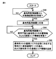
- FIG. 8 is a flowchart showing an example of a processing procedure executed by base station monitoring apparatus 301 according to the first embodiment. The following steps are realized by the CPU 302 of the base station monitoring apparatus 301 executing a program stored in the memory 304.
- CPU 302 determines whether or not a disaster occurrence notification has been received from the Japan Meteorological Agency or the like via communication interface 308 (step S52). When the disaster occurrence notification has not been received (NO in step S52), CPU 302 repeats the process of step S52. On the other hand, when a disaster occurrence notification is received (YES in step S52), CPU 302 makes a status check request to each base station via communication interface 308 (step S54).
- the CPU 302 determines whether or not there is one or more base stations that cannot be used (step S56). Specifically, when the CPU 302 receives a response signal to the state confirmation request from the base station, the CPU 302 determines that the base station is usable. On the other hand, if the response signal cannot be received from the base station, the CPU 302 determines that the base station cannot be used.
- step S56 If there is no one or more base stations that cannot be used (all base stations are usable) (NO in step S56), the CPU 302 ends the process. On the other hand, when there is one or more base stations that cannot be used (YES in step S56), the CPU 302 sends an unusable base station (in the present embodiment, the base station 101) via the communication interface 308. ), The communication area information and position information of the base station 101 are transmitted to the available base stations (in this embodiment, the base station 201) in the vicinity of () (step S58), and the process is terminated.
- the memory 304 stores communication area information and position information of each base station. Therefore, the CPU 302 can determine that the base station 201 is a usable base station existing around the base station 101 with reference to the memory 304.
- FIG. 9 is a flowchart showing an example of a processing procedure executed by the base station 201 according to the first embodiment. The following steps are realized by the CPU 202 of the base station 201 executing a program stored in the memory 204.
- CPU 202 determines whether or not a status confirmation request has been received from base station monitoring apparatus 301 (step S60). When the status confirmation request has not been received (NO in step S60), CPU 202 repeats the process of step S60. On the other hand, if a status confirmation request has been received (YES in step S60), CPU 202 transmits a response signal to the status confirmation request to base station monitoring apparatus 301 via communication interface 210 (step S60). S62).
- the CPU 202 determines whether or not the location information and communication area information of the unusable base station 101 are received from the base station monitoring apparatus 301 via the communication interface 210 (step S64). If the information has not been received (NO in step S64), CPU 202 repeats the process of step S64. On the other hand, when the information is received (YES in step S64), the CPU 202 instructs the mobile terminal device 21 existing in the vicinity of the communication area of the base station 101 to transmit the instruction information of the inter-terminal communication mode and the base station. 101 is transmitted (step S66), and the process is terminated.
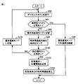
- FIG. 10 is a flowchart showing an example of a processing procedure executed by the mobile terminal device 21 according to the first embodiment. The following steps are realized by the CPU 102 of the mobile terminal device 21 executing a program stored in the memory 104.
- the CPU 102 of the mobile terminal device 21 determines whether or not the terminal station communication mode instruction information and the base station 101 communication area information are received from the base station 201 via the wireless communication unit 110. Judgment is made (step S70). If the information has not been received (NO in step S70), CPU 102 repeats the process in step S70. On the other hand, when the information is received (YES in step S70), CPU 102 activates the inter-terminal communication mode (step S72).
- the CPU 102 searches for one or more other mobile terminal devices capable of communication between terminals via the wireless communication unit 110 (step S74).
- the CPU 102 determines whether or not a response signal has been received from one or more other mobile terminal devices (step S76). If the response signal cannot be received (NO in step S76), CPU 102 repeats the process of step S74. On the other hand, when the response signal can be received (YES in step S76), the CPU 102 receives the response terminal from the other portable terminal device (response terminal) that has responded via the wireless communication unit 110.
- the position information is received (step S78).
- the response terminal is the mobile terminal device 11.
- the CPU 102 determines whether or not the response terminal exists in the communication area 1000 of the base station 101 based on the position information of the response terminal and the communication area information of the base station 101 (step S80). If no response terminal exists in communication area 1000 (NO in step S80), CPU 102 repeats the processing from step S74. On the other hand, when the response terminal exists in the communication area 1000 (YES in step S80), the CPU 102 establishes inter-terminal communication between the mobile terminal device 21 and the response terminal (step S82), and performs processing. Exit.
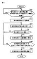
- FIG. 11 is a flowchart showing an example of a processing procedure executed by the mobile terminal device 11 according to the first embodiment. The following steps are realized by the CPU 102 of the mobile terminal device 11 executing a program stored in the memory 104.
- the CPU 102 of the mobile terminal device 11 performs a channel scan in the normal communication mode via the wireless communication unit 110 (step S90).
- the CPU 102 determines whether a response signal has been received from the base station 101 (step S92). If a response signal is received (YES in step S92), CPU 102 continues communication with another mobile terminal device in the normal communication mode (step S94) and ends the process.
- step S92 when the response signal cannot be received (NO in step S92), the CPU 102 switches the operation mode of the mobile terminal device 11 from the normal communication mode to the inter-terminal communication mode (step S96).
- the CPU 102 searches for one or more other portable terminal devices capable of inter-terminal communication via the wireless communication unit 110 (step S98).
- the CPU 102 determines whether or not a response signal has been received from one or more other mobile terminal devices (step S100). If the response signal cannot be received (NO in step S100), CPU 102 switches the operation mode from the terminal-to-terminal communication mode to the normal communication mode (step S106), and repeats the processing from step S90.
- the CPU 102 sends the mobile terminal device 11 to another mobile terminal device (response terminal) that has responded via the wireless communication unit 110. Is transmitted (step S102). Then, the CPU 102 establishes inter-terminal communication between the mobile terminal device 11 and the response terminal (step S104), and ends the process.
- the response terminal is the mobile terminal device 21.
- the portable terminal device existing in the communication area of the unusable base station and the usable state Inter-terminal communication with a mobile terminal device existing in the communication area of the base station.
- the mobile terminal device capable of inter-terminal communication establishes inter-terminal communication with surrounding mobile terminal devices one after another, it is possible to establish efficient inter-terminal communication as a whole.
- the mobile terminal device 21 communicates with another mobile terminal device in the normal communication mode when one or more other mobile terminal devices capable of inter-terminal communication cannot be searched. Different from 1.
- step S76 of FIG. 10 when mobile terminal device 21 according to the second embodiment does not receive a response signal from one or more other mobile terminal devices (NO in step S76), the mobile terminal device
- the CPU 102 (terminal search unit 154) 21 uses the timer 122 to determine whether or not a predetermined time (for example, 3 minutes) has elapsed since the search in step S74 was started.
- the CPU 102 repeats the processing from step S74.
- the CPU 102 (terminal search unit 154) determines that one or more other mobile terminal devices could not be searched. Then, the CPU 102 (terminal communication unit 160) switches the operation mode from the inter-terminal communication mode to the normal communication mode, communicates with other mobile terminal devices, and ends the process. Thereafter, when the CPU 102 receives instruction information on the communication mode between terminals from the base station 201 via the wireless communication unit 110 again, the CPU 102 activates the communication mode between terminals.
- the search is stopped and communication is performed in the normal communication mode. Therefore, it is possible to reduce power consumption due to continuing useless search.
- the third embodiment is an embodiment assuming a case where the base station 101 is changed from an unusable state to a usable state (recovered).
- the restored base station 101 sends instruction information for instructing to communicate with other mobile terminal devices in the normal communication mode to the mobile terminal devices 11 to 17 (mobile terminal devices existing in the communication area 1000). Send.
- Each of the mobile terminal devices 11 to 17 receives the instruction information from the base station 101.
- the operation mode is changed from the inter-terminal communication mode to the normal communication mode. Switch to communicate with other mobile terminal devices.
- the base station monitoring apparatus 301 receives the state confirmation response transmitted from the base station 101, the base station monitoring apparatus 301 confirms that the base station 101 has been restored. Then, the base station monitoring apparatus 301 notifies the base station 201 that the base station 101 has been restored.
- the base station 201 When the base station 201 receives the notification from the base station monitoring device 301, the base station 201 provides the mobile terminal devices 21 and 22 (in the communication area 2000 with instruction information for instructing communication with other mobile terminal devices in the normal communication mode. To the mobile terminal device).
- the mobile terminal device 21 receives the instruction information from the base station 201.
- the mobile terminal device 21 terminal communication unit 160
- the mobile terminal device 22 performs the same processing as the mobile terminal device 11.
- a program that causes a computer to function and execute control as described in the above flowchart.
- a program is recorded on a non-temporary computer-readable recording medium such as a flexible disk attached to the computer, a CD-ROM (Compact Disk Read Only Memory), a ROM, a RAM, and a memory card as a program product. It can also be provided.
- the program can be provided by being recorded on a recording medium such as a hard disk built in the computer.
- a program can also be provided by downloading via a network.
- the program may be a program module that is provided as a part of an operating system (OS) of a computer and that calls necessary modules in a predetermined arrangement at a predetermined timing to execute processing.
- OS operating system
- the program itself does not include the module, and the process is executed in cooperation with the OS.
- a program that does not include such a module can also be included in the program according to the present embodiment.
Landscapes
- Engineering & Computer Science (AREA)
- Computer Networks & Wireless Communication (AREA)
- Signal Processing (AREA)
- Databases & Information Systems (AREA)
- Mobile Radio Communication Systems (AREA)
- Telephone Function (AREA)
Abstract
基地局を介さない端末間通信を効率よく実行することが可能な携帯端末装置を提供する。端末間通信モードを利用可能な携帯端末装置は、端末間通信を行なうように指示する指示情報と、他の基地局の通信エリア情報とを受信する受信部と、端末間通信が可能な1以上の他の携帯端末装置を検索する端末検索部と、1以上の他の携帯端末装置から、当該他の携帯端末装置の位置情報を受信する位置受信部と、位置情報と通信エリア情報とに基づいて、1以上の他の携帯端末装置が他の基地局の通信エリアに存在するか否かを判断するエリア判断部と、1以上の他の携帯端末装置と通信を行なう端末通信部とを備える。端末通信部は、1以上の他の携帯端末装置が他の基地局の通信エリアに存在する場合には、当該他の携帯端末装置と端末間通信を行なう。
Description
本発明は、携帯端末装置に関し、特に、基地局を介さずに他の携帯端末装置と通信する端末間通信モードを利用可能な携帯端末装置に関する。
従来、携帯電話などの携帯端末装置は、基地局および無線通信網を介して、サーバおよび他の携帯端末装置などの通信相手と通信する。このため、地震や水害など大規模な災害が発生して基地局と無線通信網との間の通信が不能な状態になると、携帯端末装置は通信相手と通信することができない。
そこで、災害が発生した場合であっても携帯端末装置と通信相手との通信を可能とするための技術として、基地局を経由することなく、複数の携帯端末装置が直接、無線通信を実行する無線通信方式、いわゆるDevice-to-Device(D2D)通信として無線LANのアドホックモードなどが知られている。
たとえば、特開2006-319555号公報(特許文献1)では、携帯電話機能とマルチホップ通信機能とを有する携帯通信端末が開示されている。携帯通信端末は、基地局から送信される制御信号に含まれる情報に基づいて、ラジオ放送あるいはテレビジョン放送を受信するチューナを起動し、受信した緊急警報放送で災害発生を検出し、該災害発生の検出に応答してマルチホップ通信機能を起動し、該マルチホップ通信機能によってアドホックネットワークを通じて、特定の相手へのアクセスを許可して、音声またはデータを送受信する。
しかしながら、特許文献1の技術によると、携帯通信端末にチューナを搭載しておく必要があり、また、放送局からの電波が届かない場合にはマルチホップ通信機能を起動することができないため端末間通信を実現することができない。
本発明は、上記のような問題点を解決するためになされたものであって、基地局を介さない端末間通信を効率よく実行することが可能な携帯端末装置を提供することを目的とする。
ある実施の形態に従うと、基地局を介さずに他の携帯端末装置と通信する端末間通信モードを利用可能な携帯端末装置が提供される。携帯端末装置は、他の携帯端末装置と端末間通信モードによる通信を行なうように指示する第1の指示情報と、他の基地局の通信エリア情報とを基地局から受信する受信部と、携帯端末装置と端末間通信モードによる通信が可能な1以上の他の携帯端末装置を検索する端末検索部と、端末検索部により検索された1以上の他の携帯端末装置から、当該他の携帯端末装置の位置情報を受信する位置受信部と、位置情報と通信エリア情報とに基づいて、検索された1以上の他の携帯端末装置が他の基地局の通信エリアに存在するか否かを判断するエリア判断部と、検索された1以上の他の携帯端末装置と通信を行なう端末通信部とを備える。端末通信部は、検索された1以上の他の携帯端末装置が他の基地局の通信エリアに存在する場合には、当該他の携帯端末装置と端末間通信モードによる通信を行なう。
本発明によれば、基地局を介さない端末間通信を効率よく実行することが可能となる。
以下、図面を参照しつつ、本発明の実施の形態について説明する。以下の説明では、同一の部品には同一の符号を付してある。それらの名称および機能も同じである。したがって、それらについての詳細な説明は繰り返さない。また、以下では、スマートフォンを「携帯端末装置」の代表例として説明を行なう。ただし、携帯端末装置は、タブレット端末装置、ノートPC(personal computer)、PND(Personal Navigation Device)、PDA(Personal Data Assistance)などのような他の情報通信機器であってもよい。
[実施の形態1]
<システム概要>
(全体構成)
実施の形態1に従う通信システム1のシステム概要について説明する。図1は、実施の形態1に従う通信システム1の全体構成を示す概略図である。図1を参照して、通信システム1は、複数の基地局101,201と、携帯端末装置11~17,21,22と、基地局監視装置301とを含む。
<システム概要>
(全体構成)
実施の形態1に従う通信システム1のシステム概要について説明する。図1は、実施の形態1に従う通信システム1の全体構成を示す概略図である。図1を参照して、通信システム1は、複数の基地局101,201と、携帯端末装置11~17,21,22と、基地局監視装置301とを含む。
基地局101,201は、たとえば、3GPP(Third Generation Partnership Project)において標準化されている無線通信アクセス技術(RAT:Radio Access Technology)のうち、LTE(Long Term Evolution)に従った動作を実行する。
通信システム1では、災害の発生によって、基地局101が使用不能な状態となっている。基地局201は、通信エリア(セル)2000を構成する。なお、通信エリア1000は、基地局101が使用可能な状態にある場合の基地局101の通信エリアである。
携帯端末装置11~17,21,22は、LTEなどの無線アクセス技術に従った無線通信を実行するUE(User Equipment)である。これらの携帯端末装置は、LTE通信を用いて、動作モードとして、基地局を介して他の携帯端末装置と通信する通常通信モードと、基地局を介さずに他の携帯端末装置と直接通信する端末間通信(D2D通信)モードとを利用可能に構成されている。
通信システム1では、携帯端末装置11~17は、通信エリア1000内に存在しているが、基地局101は使用不能な状態であるため通常通信モードによる通信(通常通信)はできず、端末間通信モードによる通信(端末間通信)のみが可能である。一方、携帯端末装置21,22は、使用可能な状態である基地局201が構成する通信エリア2000内に存在しているため、通常通信および端末間通信が可能である。
基地局監視装置301は、有線通信網500を介して基地局101,201と通信可能に構成されている。基地局監視装置301は、基地局101,201が正常に動作しているかどうかを監視する。具体的には、基地局監視装置301は、気象庁から配信される緊急地震速報などの災害情報を受信すると、基地局101,201に対して状態確認要求を行ない、基地局101,201が正常動作しているか否かを確認する。
(動作概要)
図2は、実施の形態1に従う通信システム1の動作概要を示すシーケンス図である。なお、上述したように、基地局101は被災して使用不能な状態であるとする。なお、使用可能な状態である基地局201は、通信エリア2000内に存在する携帯端末装置21,22の各々から、当該携帯端末装置の位置情報を定期的に受信しており、携帯端末装置21,22の位置を把握している。
図2は、実施の形態1に従う通信システム1の動作概要を示すシーケンス図である。なお、上述したように、基地局101は被災して使用不能な状態であるとする。なお、使用可能な状態である基地局201は、通信エリア2000内に存在する携帯端末装置21,22の各々から、当該携帯端末装置の位置情報を定期的に受信しており、携帯端末装置21,22の位置を把握している。
図2を参照して、基地局監視装置301は、気象庁から緊急地震速報等の災害発生通知を受信する(ステップS10)。基地局監視装置301は、災害発生通知を受信すると、基地局101に状態確認要求を送信する(ステップS12)。状態確認要求とは、基地局が使用可能な状態(通信可能な状態)か否かを確認するための要求である。基地局101は、使用不能な状態であることから当該要求に対して応答することはできない。そのため、基地局監視装置301は、基地局101が使用不能な状態であると判断する。
また、基地局監視装置301は、基地局201に状態確認要求を送信する(ステップS14)。基地局201は、使用可能な状態であるため基地局監視装置301に対して状態確認応答を送信する(ステップS16)。具体的には、基地局201は、使用可能な状態であることを示す応答信号を基地局監視装置301に送信する。なお、基地局監視装置301は、ステップS12およびステップS14の処理を並行して行なってもよい。
基地局監視装置301は、基地局201から状態確認応答を受信すると、使用不能な状態である基地局101の通信エリア情報および位置情報を基地局201に送信する(ステップS18)。
一方、携帯端末装置11(図2中の「端末11」)は、通常通信モードによりチャネルスキャンを実行する(ステップS20)。具体的には、携帯端末装置11は、通信チャネルを変化させながら、基地局が発する信号の受信を試みて基地局のチャネル検索を行ない、基地局の検索を行なう。通信システム1では、基地局101は使用不能な状態であるため、携帯端末装置11は基地局101からの応答信号を受信することはできない。
この場合、携帯端末装置11は、通常通信モードから端末間通信モードに切り替えて、端末間通信が可能な他の携帯端末装置を検索する。具体的には、携帯端末装置11は、検索用の要求信号を1以上の他の携帯端末装置に送信する。
そして、他の携帯端末装置が発見できなかった(他の携帯端末装置から応答信号を受信できなかった)場合には、携帯端末装置11は、端末間通信モードから通常通信モードに切り替えて、チャネルスキャンを再度実行する。このように、携帯端末装置11は、通常通信モードおよび端末間通信モードを交互に切り替えながら他の携帯端末装置との通信を試みる(ステップS22)。
また、基地局201は、基地局101の通信エリア情報および位置情報を基地局監視装置301から受信すると、他の携帯端末装置と端末間通信モードによる通信を行なうように携帯端末装置21(図2中の「端末21」)に指示する(ステップS24)。具体的には、基地局201は、基地局101の通信エリア情報と携帯端末装置21,22の位置情報とに基づいて、携帯端末装置21が基地局101の通信エリア1000に近い位置に存在すると判断し、携帯端末装置21に当該指示を出す。
なお、基地局201は、通信事業者が管轄する無線通信網において用いられる周波数帯域での端末間通信を携帯端末装置21に行なわせるため、当該端末間通信を制御するための制御情報を携帯端末装置21に送信してもよい。制御情報は、無線通信網を利用した端末間通信を許可するための許可情報、および当該端末間通信に必要となる通信環境の設定情報を含む。たとえば、設定情報は、端末間通信で許容される周波数帯などの無線リソース情報、無線信号の電波強度を含む。
携帯端末装置21は、当該指示を受け付けると端末間通信モードを起動する(ステップS26)。また、基地局201は、基地局101の通信エリア情報を携帯端末装置21に送信する(ステップS28)。なお、基地局201は、携帯端末装置21に基地局101の位置情報をさらに送信するように構成されていてもよい。
上記において、基地局201は、ステップS24における端末間通信モードの動作指示の処理と、ステップS28における基地局101の通信エリア情報(および位置情報)を送信する処理とを同時に行なうように構成されていてもよい。
携帯端末装置21は、端末間通信可能な1以上の他の携帯端末装置を検索(サーチ)する(ステップS30)。具体的には、携帯端末装置21は、検索用の要求信号を1以上の他の携帯端末装置に送信する。携帯端末装置21は、たとえば、電話番号、メールアドレスなどの識別情報に基づいて、これらの他の携帯端末装置を一意に識別可能である。
携帯端末装置11は、携帯端末装置21から送信される要求信号を受信できた場合、応答信号を携帯端末装置21に送信する(ステップS32)。携帯端末装置21は、応答信号を受信すると携帯端末装置11が検索されたことを確認する。
また、携帯端末装置11は、自装置の位置情報を送信する(ステップS34)。携帯端末装置21は、検索された携帯端末装置11の位置情報と、基地局101の通信エリア情報とに基づいて、携帯端末装置11が基地局101の通信エリア1000内に存在すること判断する(ステップS36)。そして、携帯端末装置11および携帯端末装置21間の端末間通信が確立する(ステップS38)。具体的には、携帯端末装置11および携帯端末装置21は、端末間通信モードにより各種データ(災害通知情報、アプリケーションなど)の送受信を行なう。なお、携帯端末装置21は、基地局201から受信した制御情報を携帯端末装置11に送信してもよい。
上記のステップS30において、携帯端末装置21は、携帯端末装置11の他に携帯端末装置16も検索した場合には、上述した携帯端末装置11との間で行なった処理と同じ処理を携帯端末装置16とも行ない、携帯端末装置16と端末間通信を確立する。
通信エリア2000内に存在する携帯端末装置21との端末間通信が確立した携帯端末装置11は、さらに端末間通信可能な他の携帯端末装置を検索する。そして、携帯端末装置11は、検索された携帯端末装置12および携帯端末装置16と端末間通信を確立する。同様に、携帯端末装置16は、携帯端末装置11,17,21との間で端末間通信を確立し、携帯端末装置12は、携帯端末装置11,13との間で端末間通信を確立し、携帯端末装置13は、携帯端末装置14,15との間で端末間通信を確立する。
このように、基地局101が使用不能な状態であっても、通信エリア1000内に存在する携帯端末装置11~17と、使用可能な状態である基地局201の通信エリア2000内に存在する携帯端末装置21との通信が可能となる。
なお、各々の携帯端末装置は、他の携帯端末装置と端末間通信モードによる通信を行なう場合には、予め定められた個数(たとえば、8台)の携帯端末装置とのみ通信するように構成されていてもよい。あるいは、各々の携帯端末装置は、他の携帯端末装置が検索されたときの自装置の電池残量に基づいて、通信相手となる携帯端末装置の個数を決定してもよい。
<ハードウェア構成>
(携帯端末装置)
図3は、実施の形態1に従う携帯端末装置21のハードウェア構成を示すブロック図である。図3を参照して、携帯端末装置21は、主たる構成要素として、CPU(Central Processing Unit)102と、メモリ104と、タッチパネル106と、ディスプレイ108と、無線通信部110と、メモリインターフェイス(I/F)114と、通信インターフェイス(I/F)116と、GPS(Global Positioning System)コントローラ118と、バッテリ120と、タイマー122とを含む。なお、携帯端末装置11~17,22も携帯端末装置21と同様のハードウェア構成を有する。
(携帯端末装置)
図3は、実施の形態1に従う携帯端末装置21のハードウェア構成を示すブロック図である。図3を参照して、携帯端末装置21は、主たる構成要素として、CPU(Central Processing Unit)102と、メモリ104と、タッチパネル106と、ディスプレイ108と、無線通信部110と、メモリインターフェイス(I/F)114と、通信インターフェイス(I/F)116と、GPS(Global Positioning System)コントローラ118と、バッテリ120と、タイマー122とを含む。なお、携帯端末装置11~17,22も携帯端末装置21と同様のハードウェア構成を有する。
CPU102は、メモリ104に記憶されたプログラムを読み出して実行することで、携帯端末装置21の各部の動作を制御する。より詳細にはCPU102は、当該プログラムを実行することによって、後述する携帯端末装置21の処理(ステップ)の各々を実現する。
メモリ104は、RAM(Random Access Memory)、ROM(Read-Only Memory)、フラッシュメモリなどによって実現される。メモリ104は、CPU102によって実行されるプログラム、またはCPU102によって用いられるデータなどを記憶する。タッチパネル106は、表示部としての機能を有するディスプレイ108上に設けられており、たとえば、静電容量方式タイプである。タッチパネル106は、所定時間毎に外部物体によるタッチパネル106へのタッチ操作を検知し、タッチ座標をCPU102に入力する。
無線通信部110は、通信アンテナ112を介して無線通信網に接続し無線通信のための信号を送受信する。これにより、携帯端末装置21は、たとえば、LTE(Long Term Evolution)などの無線通信網を利用して、基地局を介して他の携帯端末装置と通信を実行することができ、また、基地局を介さずに他の携帯端末装置と端末間通信を実行することができる。
メモリインターフェイス(I/F)114は、外部の記憶媒体115からデータを読み出す。CPU102は、メモリ104からデータを読み出して、メモリインターフェイス114を介して当該データを外部の記憶媒体115に格納する。なお、記憶媒体115としては、CD(Compact Disc)、DVD(Digital Versatile Disk)、BD(Blu-ray(登録商標) Disc)、USB(Universal Serial Bus)メモリ、SD(Secure Digital)メモリカードなどの不揮発的にプログラムを格納する媒体が挙げられる。
通信インターフェイス(I/F)116は、外部装置との間で各種データをやり取りするものであり、アダプタやコネクタなどによって実現される。なお、通信方式としては、たとえば、Bluetooth(登録商標)、無線LAN(Local Area Network)などによる無線通信であってもよいし、USB(Universal Serial Bus)などを利用した有線通信であってもよい。
GPSコントローラ118は、GPS信号または基地局からの位置信号(測位信号)を受信して携帯端末装置21の位置情報を取得する。GPSコントローラ118は、取得した携帯端末装置21の位置情報をCPU102に入力する。バッテリ120は、充放電可能な電力貯蔵要素であり、代表的にはリチウムイオン電池やニッケル水素電池などの二次電池で構成される。タイマー122は、時刻を計時し、計時した時刻に応じた信号をCPU102に送出する。CPU102は、当該信号に基づき、予め定められた処理をする。
なお、携帯端末装置21は、ユーザからの指示を受け付けるためのボタン、携帯端末装置21に対する発話を受け付けるマイク、音声を出力するためのスピーカを含んでいてもよい。
(基地局)
図4は、実施の形態1に従う基地局201のハードウェア構成を示すブロック図である。図4を参照して、基地局201は、主たる構成要素として、各種処理を実行するためのCPU202と、CPU202によって実行されるプログラム、各種データなどを格納するためのメモリ204と、無線通信網を介して通信エリア2000内の装置と各種データを送受信するための無線通信部206と、基地局監視装置301と通信するための通信インターフェイス(I/F)210とを含む。なお、基地局101も基地局201と同様のハードウェア構成を有する。
図4は、実施の形態1に従う基地局201のハードウェア構成を示すブロック図である。図4を参照して、基地局201は、主たる構成要素として、各種処理を実行するためのCPU202と、CPU202によって実行されるプログラム、各種データなどを格納するためのメモリ204と、無線通信網を介して通信エリア2000内の装置と各種データを送受信するための無線通信部206と、基地局監視装置301と通信するための通信インターフェイス(I/F)210とを含む。なお、基地局101も基地局201と同様のハードウェア構成を有する。
メモリ204には、基地局201の通信エリア情報および位置情報が登録(格納)されている。また、CPU202は、各々の携帯端末装置から送信される当該携帯端末装置の位置情報を無線通信部206および通信アンテナ208を介して受信して、メモリ204に各位置情報を格納する。また、CPU202は、基地局監視装置301から送信される他の基地局の通信エリア情報および位置情報を通信インターフェイス210を介して受信して、当該通信エリア情報および位置情報をメモリ204に格納する。
(基地局監視装置)
図5は、実施の形態1に従う基地局監視装置301のハードウェア構成を示すブロック図である。図5を参照して、基地局監視装置301は、主たる構成要素として、各種処理を実行するためのCPU302と、CPU302によって実行されるプログラム、各種データなどを格納するためのメモリ304と、複数の基地局と通信するための通信インターフェイス(I/F)308とを含む。メモリ304には、各々の基地局の通信エリア情報および位置情報が登録(格納)されている。
図5は、実施の形態1に従う基地局監視装置301のハードウェア構成を示すブロック図である。図5を参照して、基地局監視装置301は、主たる構成要素として、各種処理を実行するためのCPU302と、CPU302によって実行されるプログラム、各種データなどを格納するためのメモリ304と、複数の基地局と通信するための通信インターフェイス(I/F)308とを含む。メモリ304には、各々の基地局の通信エリア情報および位置情報が登録(格納)されている。
<機能構成>
図6を参照して、実施の形態1に従う携帯端末装置21の機能構成について説明する。図6は、実施の形態1に従う携帯端末装置21の機能ブロック図である。なお、携帯端末装置11~17,22も携帯端末装置21と同様の機能構成を有する。
図6を参照して、実施の形態1に従う携帯端末装置21の機能構成について説明する。図6は、実施の形態1に従う携帯端末装置21の機能ブロック図である。なお、携帯端末装置11~17,22も携帯端末装置21と同様の機能構成を有する。
図6を参照して、携帯端末装置21は、その主たる機能構成として、基地局情報受信部152と、端末検索部154と、端末情報受信部156と、エリア判断部158と、端末通信部160とを含む。これらの機能は、主に、携帯端末装置21のCPU102がメモリ104に格納されたプログラムを実行し、携帯端末装置21の構成要素へ指令を与えることなどによって実現される。CPU102は、携帯端末装置21の動作全体を制御する制御部としての機能を有する。なお、これらの機能構成の一部または全部はハードウェアで実現されていてもよい。
基地局情報受信部152は、他の携帯端末装置と端末間通信モードによる通信を行なうように指示する指示情報を基地局201から受信する。また、基地局情報受信部152は、他の基地局の通信エリア情報を基地局201から受信する。具体的には、基地局情報受信部152は、使用不能になった基地局101の通信エリア情報を基地局201から受信する。なお、基地局情報受信部152は、他の基地局の位置情報を基地局201から受信してもよい。
端末検索部154は、携帯端末装置と端末間通信モードによる通信が可能な1以上の他の携帯端末装置を検索(サーチ)する。具体的には、端末検索部154は、検索用の要求信号を1以上の他の携帯端末装置に送信することにより当該他の携帯端末装置を検索する。たとえば、端末検索部154は、携帯端末装置11から応答信号を受信すると、携帯端末装置11が検索されたと判断する。なお、端末検索部154は、検索用の要求信号が到達する範囲内で、端末間通信が可能な他の携帯端末装置を検索できる。
端末情報受信部156は、端末検索部154により検索された1以上の他の携帯端末装置から、当該他の携帯端末装置の位置情報を受信する。なお、端末情報受信部156は、当該他の携帯端末装置から識別情報(電話番号など)を受信してもよい。
エリア判断部158は、検索された当該他の携帯端末装置の位置情報と基地局101の通信エリア情報とに基づいて、検索された当該他の携帯端末装置が基地局101の通信エリア1000内に存在するか否かを判断する。
端末通信部160は、検索された1以上の他の携帯端末装置と通信を行なう。具体的には、端末通信部160は、通常通信モードまたは端末間通信モードのいずれかで他の携帯端末装置と通信可能に構成されている。端末通信部160は、検索された1以上の他の携帯端末装置が基地局101の通信エリアに存在する場合には、当該他の携帯端末装置と端末間通信モードによる通信を行なう。
また、端末通信部160は、端末検索部154により複数の他の携帯端末装置が検索された場合、当該複数の他の携帯端末装置のうち予め定められた個数(たとえば、8つ)の他の携帯端末装置と端末間通信モードによる通信を行なう。たとえば、端末通信部160は、検索された順に上位8つの携帯端末装置と端末間通信モードによる通信を行なう。また、端末通信部160は、自装置の位置情報と複数の他の携帯端末装置の各位置情報とに基づいて、自装置の位置に近い順に上位8つの携帯端末装置と端末間通信モードによる通信を行なってもよい。なお、当該個数はメモリ104に記憶されている。
残量検出部162は、携帯端末装置21のバッテリ120の電池残量を検出する。ここで、メモリ204には、携帯端末装置21の電池残量の範囲と、端末間通信モードによる通信の相手とする他の携帯端末装置の個数とを関連付けた端末数テーブル600が記憶されている。
図7は、実施の形態1に従う端末数テーブル600を示す図である。なお、電池残量Qは、満充電容量に対する現在の残容量を百分率(0~100%)で示したものである。
図7を参照して、電池残量Q<20%の場合には、通信相手とする他の携帯端末装置の個数は0である。20%≦電池残量Q<30%の場合には当該個数は1つであり、30%≦電池残量Q<50%の場合には当該個数は3つであり、50%≦電池残量Q<80%の場合には当該個数は5つであり、80%≦電池残量Qの場合には当該個数は8つである。
再び図6を参照して、端末検索部154が複数の他の携帯端末装置を検索した場合には、端末通信部160は、残量検出部162により検出された電池残量と端末数テーブルとに基づいて通信相手とする他の携帯端末装置の個数を算出する。端末通信部160は、複数の他の携帯端末装置のうち当該算出された個数の他の携帯端末装置と端末間通信モードによる通信を行なう。たとえば、8つの他の携帯端末装置が検索されており、携帯端末装置21の電池残量が60%の場合には、端末通信部160は、検索された順に上位5つの他の携帯端末装置と端末間通信モードによる通信を行なう。また、端末通信部160は、自装置の位置に近い順に上位5つの他の携帯端末装置と端末間通信モードによる通信を行なってもよい。
<処理手順>
図8は、実施の形態1に従う基地局監視装置301が実行する処理手順の一例を示すフローチャートである。以下の各ステップは、基地局監視装置301のCPU302がメモリ304に格納されたプログラムを実行することによって実現される。
図8は、実施の形態1に従う基地局監視装置301が実行する処理手順の一例を示すフローチャートである。以下の各ステップは、基地局監視装置301のCPU302がメモリ304に格納されたプログラムを実行することによって実現される。
図8を参照して、CPU302は、通信インターフェイス308を介して、気象庁などから災害発生通知を受信したか否かを判断する(ステップS52)。災害発生通知を受信していない場合には(ステップS52においてNO)、CPU302はステップS52の処理を繰り返す。これに対して、災害発生通知を受信した場合には(ステップS52においてYES)、CPU302は、通信インターフェイス308を介して、各基地局に状態確認要求を行なう(ステップS54)。
CPU302は、使用不能な1以上の基地局が存在するか否かを判断する(ステップS56)。具体的には、CPU302は、状態確認要求に対する応答信号を当該基地局から受信した場合には、当該基地局は使用可能であると判断する。一方、CPU302は、当該応答信号を当該基地局から受信できなかった場合には、当該基地局は使用不能であると判断する。
使用不能な1以上の基地局が存在しない(全ての基地局が使用可能である)場合には(ステップS56においてNO)、CPU302は処理を終了する。これに対して、使用不能な1以上の基地局が存在する場合には(ステップS56においてYES)、CPU302は、通信インターフェイス308を介して、使用不能な基地局(本実施形態では、基地局101)の周辺の使用可能な基地局(本実施形態では、基地局201)に、基地局101の通信エリア情報および位置情報を送信して(ステップS58)、処理を終了する。メモリ304には各基地局の通信エリア情報および位置情報が格納されている。そのため、CPU302は、メモリ304を参照して、基地局201が基地局101の周辺に存在する使用可能な基地局であると判断することができる。
図9は、実施の形態1に従う基地局201が実行する処理手順の一例を示すフローチャートである。以下の各ステップは、基地局201のCPU202がメモリ204に格納されたプログラムを実行することによって実現される。
CPU202は、基地局監視装置301から状態確認要求を受信したか否かを判断する(ステップS60)。状態確認要求を受信していない場合には(ステップS60においてNO)、CPU202はステップS60の処理を繰り返す。これに対して、状態確認要求を受信している場合には(ステップS60においてYES)、CPU202は、通信インターフェイス210を介して、状態確認要求に対する応答信号を基地局監視装置301に送信する(ステップS62)。
CPU202は、通信インターフェイス210を介して、基地局監視装置301から使用不能な基地局101の位置情報および通信エリア情報を受信したか否かを判断する(ステップS64)。当該情報を受信していない場合には(ステップS64においてNO)、CPU202はステップS64の処理を繰り返す。これに対して、当該情報を受信した場合には(ステップS64においてYES)、CPU202は、基地局101の通信エリアの近傍に存在する携帯端末装置21に端末間通信モードの指示情報、および基地局101の通信エリア情報を送信して(ステップS66)、処理を終了する。
図10は、実施の形態1に従う携帯端末装置21が実行する処理手順の一例を示すフローチャートである。以下の各ステップは、携帯端末装置21のCPU102がメモリ104に格納されたプログラムを実行することによって実現される。
図10を参照して、携帯端末装置21のCPU102は、無線通信部110を介して、基地局201から端末間通信モードの指示情報と基地局101の通信エリア情報とを受信したか否かを判断する(ステップS70)。当該情報を受信していない場合には(ステップS70においてNO)、CPU102はステップS70の処理を繰り返す。これに対して、当該情報を受信した場合には(ステップS70においてYES)、CPU102は、端末間通信モードを起動する(ステップS72)。
CPU102は、無線通信部110を介して、端末間通信可能な1以上の他の携帯端末装置を検索する(ステップS74)。CPU102は、1以上の他の携帯端末装置から応答信号を受信したか否かを判断する(ステップS76)。応答信号を受信できない場合には(ステップS76においてNO)、CPU102はステップS74の処理を繰り返す。これに対して、応答信号を受信できた場合には(ステップS76においてYES)、CPU102は、無線通信部110を介して、応答があった他の携帯端末装置(応答端末)から当該応答端末の位置情報を受信する(ステップS78)。本実施の形態では、当該応答端末は携帯端末装置11である。
CPU102は、応答端末の位置情報と基地局101の通信エリア情報とに基づいて、応答端末が基地局101の通信エリア1000内に存在するか否かを判断する(ステップS80)。応答端末が通信エリア1000内に存在しない場合には(ステップS80においてNO)、CPU102はステップS74からの処理を繰り返す。これに対して、応答端末が通信エリア1000内に存在する場合には(ステップS80においてYES)、CPU102は、携帯端末装置21と応答端末との端末間通信を確立して(ステップS82)、処理を終了する。
図11は、実施の形態1に従う携帯端末装置11が実行する処理手順の一例を示すフローチャートである。以下の各ステップは、携帯端末装置11のCPU102がメモリ104に格納されたプログラムを実行することによって実現される。
図11を参照して、携帯端末装置11のCPU102は、無線通信部110を介して、通常通信モードによりチャネルスキャンを実行する(ステップS90)。CPU102は、基地局101から応答信号を受信したか否かを判断する(ステップS92)。応答信号を受信した場合には(ステップS92においてYES)、CPU102は、他の携帯端末装置と通常通信モードによる通信を継続して(ステップS94)、処理を終了する。
これに対して、応答信号を受信できない場合には(ステップS92においてNO)、CPU102は、携帯端末装置11の動作モードを通常通信モードから端末間通信モードに切り替える(ステップS96)。
CPU102は、無線通信部110を介して、端末間通信可能な1以上の他の携帯端末装置を検索する(ステップS98)。CPU102は、1以上の他の携帯端末装置から応答信号を受信したか否かを判断する(ステップS100)。応答信号を受信できない場合には(ステップS100においてNO)、CPU102は、動作モードを端末間通信モードから通常通信モードに切り替えて(ステップS106)、ステップS90からの処理を繰り返す。これに対して、応答信号を受信できた場合には(ステップS100においてYES)、CPU102は、無線通信部110を介して、応答があった他の携帯端末装置(応答端末)に携帯端末装置11の位置情報を送信する(ステップS102)。そして、CPU102は、携帯端末装置11と応答端末との端末間通信を確立して(ステップS104)、処理を終了する。本実施の形態では、当該応答端末は携帯端末装置21である。
実施の形態1によると、災害などにより基地局が使用不能な状態になった場合であっても、使用不能な状態になった基地局の通信エリアに存在する携帯端末装置と、使用可能な状態の基地局の通信エリアに存在する携帯端末装置との端末間通信が可能となる。また、端末間通信が可能になった携帯端末装置は、周囲の携帯端末装置と次々に端末間通信を確立していくため、全体として効率のよい端末間通信を確立することができる。
[実施の形態2]
次に、実施の形態2について説明する。実施の形態2では、携帯端末装置21は、端末間通信可能な1以上の他の携帯端末装置を検索できなかった場合、通常通信モードにより他の携帯端末装置と通信を行なう点が実施の形態1と異なる。
次に、実施の形態2について説明する。実施の形態2では、携帯端末装置21は、端末間通信可能な1以上の他の携帯端末装置を検索できなかった場合、通常通信モードにより他の携帯端末装置と通信を行なう点が実施の形態1と異なる。
具体的には、図10のステップS76において、実施の形態2に従う携帯端末装置21が1以上の他の携帯端末装置からの応答信号を受信しない場合には(ステップS76においてNO)、携帯端末装置21のCPU102(端末検索部154)は、タイマー122を用いて、ステップS74における検索を開始してから所定時間(たとえば、3分)が経過したか否かを判断する。
所定時間が経過していない場合には、CPU102はステップS74からの処理を繰り返す。これに対して、所定時間が経過している場合には、CPU102(端末検索部154)は1以上の他の携帯端末装置が検索できなかったと判断する。そして、CPU102(端末通信部160)は、動作モードを端末間通信モードから通常通信モードに切り替えて他の携帯端末装置と通信し、処理を終了する。その後、CPU102は、無線通信部110を介して、基地局201から端末間通信モードの指示情報を再度受信した場合には、端末間通信モードを起動する。
実施の形態2によると、端末間通信可能な携帯端末装置を発見できない場合には、サーチを停止して通常通信モードにより通信を行なう。そのため、無駄なサーチを継続することによる電力消費を低減できる。
[実施の形態3]
次に、実施の形態3について説明する。実施の形態3は、基地局101が使用不能な状態から使用可能な状態になった(復旧した)場合を想定した実施の形態である。
次に、実施の形態3について説明する。実施の形態3は、基地局101が使用不能な状態から使用可能な状態になった(復旧した)場合を想定した実施の形態である。
具体的には、復旧した基地局101は、通常通信モードにより他の携帯端末装置と通信するように指示する指示情報を携帯端末装置11~17(通信エリア1000内に存在する携帯端末装置)に送信する。
携帯端末装置11~17の各々は、当該指示情報を基地局101から受信する。そして、携帯端末装置11~17の各々は、他の携帯端末装置と端末間通信モードによる通信を行なっている場合において当該指示情報を受信したとき、動作モードを端末間通信モードから通常通信モードに切り替えて他の携帯端末装置と通信する。
また、基地局監視装置301は、基地局101から送信される状態確認応答を受信すると、基地局101が復旧したことを確認する。そして、基地局監視装置301は、基地局101が復旧した旨を基地局201に通知する。
基地局201は、基地局監視装置301から当該通知を受信すると、通常通信モードにより他の携帯端末装置と通信するように指示する指示情報を携帯端末装置21,22(通信エリア2000内に存在する携帯端末装置)に送信する。
たとえば、携帯端末装置21(基地局情報受信部152)は、当該指示情報を基地局201から受信する。携帯端末装置21(端末通信部160)は、他の携帯端末装置と端末間通信モードによる通信を行なっている場合において当該指示情報を受信したとき、動作モードを端末間通信モードから通常通信モードに切り替えて他の携帯端末装置と通信する。携帯端末装置22も携帯端末装置11と同様の処理を行なう。
[その他の実施の形態]
なお、コンピュータを機能させて、上述のフローチャートで説明したような制御を実行させるプログラムを提供することもできる。このようなプログラムは、コンピュータに付属するフレキシブルディスク、CD-ROM(Compact Disk Read Only Memory)、ROM、RAMおよびメモリカードなどの一時的でないコンピュータ読取り可能な記録媒体にて記録させて、プログラム製品として提供することもできる。あるいは、コンピュータに内蔵するハードディスクなどの記録媒体にて記録させて、プログラムを提供することもできる。また、ネットワークを介したダウンロードによって、プログラムを提供することもできる。
なお、コンピュータを機能させて、上述のフローチャートで説明したような制御を実行させるプログラムを提供することもできる。このようなプログラムは、コンピュータに付属するフレキシブルディスク、CD-ROM(Compact Disk Read Only Memory)、ROM、RAMおよびメモリカードなどの一時的でないコンピュータ読取り可能な記録媒体にて記録させて、プログラム製品として提供することもできる。あるいは、コンピュータに内蔵するハードディスクなどの記録媒体にて記録させて、プログラムを提供することもできる。また、ネットワークを介したダウンロードによって、プログラムを提供することもできる。
プログラムは、コンピュータのオペレーティングシステム(OS)の一部として提供されるプログラムモジュールのうち、必要なモジュールを所定の配列で所定のタイミングで呼出して処理を実行させるものであってもよい。その場合、プログラム自体には上記モジュールが含まれずOSと協働して処理が実行される。このようなモジュールを含まないプログラムも、本実施の形態にかかるプログラムに含まれ得る。
今回開示された実施の形態はすべての点で例示であって制限的なものではないと考えられるべきである。本発明の範囲は、上記した説明ではなく、請求の範囲によって示され、請求の範囲と均等の意味および範囲内でのすべての変更が含まれることが意図される。
1 通信システム、11~17,21,22 携帯端末装置、101,201 基地局、104,204,304 メモリ、106 タッチパネル、108 ディスプレイ、110,206 無線通信部、112,208 通信アンテナ、114 メモリインターフェイス、115 記憶媒体、118 GPSコントローラ、120 バッテリ、122 タイマー、152 基地局情報受信部、154 端末検索部、156 端末情報受信部、158 エリア判断部、160 端末通信部、162 残量検出部、210,308 通信インターフェイス、301 基地局監視装置、500 有線通信網、600 端末数テーブル、1000,2000 通信エリア。
Claims (5)
- 基地局を介さずに他の携帯端末装置と通信する端末間通信モードを利用可能な携帯端末装置であって、
前記他の携帯端末装置と前記端末間通信モードによる通信を行なうように指示する第1の指示情報と、他の基地局の通信エリア情報とを前記基地局から受信する受信部と、
前記携帯端末装置と前記端末間通信モードによる通信が可能な1以上の他の携帯端末装置を検索する端末検索部と、
前記端末検索部により検索された1以上の他の携帯端末装置から、当該他の携帯端末装置の位置情報を受信する位置受信部と、
前記位置情報と前記通信エリア情報とに基づいて、前記検索された1以上の他の携帯端末装置が前記他の基地局の通信エリアに存在するか否かを判断するエリア判断部と、
前記検索された1以上の他の携帯端末装置と通信を行なう端末通信部とを備え、
前記端末通信部は、前記検索された1以上の他の携帯端末装置が前記他の基地局の通信エリアに存在する場合には、当該他の携帯端末装置と前記端末間通信モードによる通信を行なう、携帯端末装置。 - 前記端末検索部が前記1以上の他の携帯端末装置を検索できなかった場合、前記端末通信部は、前記基地局を介して通信する通常通信モードにより前記他の携帯端末装置と通信する、請求項1に記載の携帯端末装置。
- 前記受信部は、前記基地局を介して通信する通常通信モードにより前記他の携帯端末装置と通信するように指示する第2の指示情報を前記基地局からさらに受信し、
前記端末通信部が前記他の携帯端末装置と前記端末間通信モードによる通信を行なっている場合において前記受信部により前記第2の指示情報が受信されたとき、前記端末通信部は、前記携帯端末装置の動作モードを前記端末間通信モードから前記通常通信モードに切り替えて前記他の携帯端末装置と通信する、請求項1または2に記載の携帯端末装置。 - 前記端末検索部が複数の前記他の携帯端末装置を検索した場合、前記端末通信部は、複数の前記他の携帯端末装置のうち予め定められた個数の他の携帯端末装置と前記端末間通信モードによる通信を行なう、請求項1~3のいずれか1項に記載の携帯端末装置。
- 前記携帯端末装置の電池残量の範囲と、前記端末間通信モードによる通信の相手とする他の携帯端末装置の個数とを関連付けた端末数情報を記憶する記憶部と、
前記携帯端末装置の電池残量を検出する残量検出部とをさらに備え、
前記端末検索部が複数の前記他の携帯端末装置を検索した場合、前記端末通信部は、前記検出された電池残量と前記端末数情報とに基づいて前記通信の相手とする他の携帯端末装置の個数を算出し、複数の前記他の携帯端末装置のうち前記算出された個数の他の携帯端末装置と前記端末間通信モードによる通信を行なう、請求項1~3のいずれか1項に記載の携帯端末装置。
Applications Claiming Priority (2)
| Application Number | Priority Date | Filing Date | Title |
|---|---|---|---|
| JP2014035597A JP2015162737A (ja) | 2014-02-26 | 2014-02-26 | 携帯端末装置 |
| JP2014-035597 | 2014-02-26 |
Publications (1)
| Publication Number | Publication Date |
|---|---|
| WO2015129305A1 true WO2015129305A1 (ja) | 2015-09-03 |
Family
ID=54008635
Family Applications (1)
| Application Number | Title | Priority Date | Filing Date |
|---|---|---|---|
| PCT/JP2015/050608 Ceased WO2015129305A1 (ja) | 2014-02-26 | 2015-01-13 | 携帯端末装置 |
Country Status (2)
| Country | Link |
|---|---|
| JP (1) | JP2015162737A (ja) |
| WO (1) | WO2015129305A1 (ja) |
Cited By (1)
| Publication number | Priority date | Publication date | Assignee | Title |
|---|---|---|---|---|
| CN109716823A (zh) * | 2016-08-29 | 2019-05-03 | 昕诺飞控股有限公司 | 作为应急连接基础设施的户外照明网络 |
Families Citing this family (1)
| Publication number | Priority date | Publication date | Assignee | Title |
|---|---|---|---|---|
| JP6385298B2 (ja) * | 2015-03-03 | 2018-09-05 | シャープ株式会社 | 通信システム |
Citations (3)
| Publication number | Priority date | Publication date | Assignee | Title |
|---|---|---|---|---|
| JP2000349787A (ja) * | 1999-03-29 | 2000-12-15 | Nec Corp | 無線lanシステム、その障害救済方法及びその障害救済処理を実現するためのコンピュータプログラムを記録した記録媒体 |
| JP2006115354A (ja) * | 2004-10-15 | 2006-04-27 | Ntt Docomo Inc | 移動端末、制御装置及び移動通信方法 |
| JP2007312066A (ja) * | 2006-05-18 | 2007-11-29 | Nec Infrontia Corp | 警備システム、警備端末および警備方法 |
-
2014
- 2014-02-26 JP JP2014035597A patent/JP2015162737A/ja active Pending
-
2015
- 2015-01-13 WO PCT/JP2015/050608 patent/WO2015129305A1/ja not_active Ceased
Patent Citations (3)
| Publication number | Priority date | Publication date | Assignee | Title |
|---|---|---|---|---|
| JP2000349787A (ja) * | 1999-03-29 | 2000-12-15 | Nec Corp | 無線lanシステム、その障害救済方法及びその障害救済処理を実現するためのコンピュータプログラムを記録した記録媒体 |
| JP2006115354A (ja) * | 2004-10-15 | 2006-04-27 | Ntt Docomo Inc | 移動端末、制御装置及び移動通信方法 |
| JP2007312066A (ja) * | 2006-05-18 | 2007-11-29 | Nec Infrontia Corp | 警備システム、警備端末および警備方法 |
Cited By (3)
| Publication number | Priority date | Publication date | Assignee | Title |
|---|---|---|---|---|
| CN109716823A (zh) * | 2016-08-29 | 2019-05-03 | 昕诺飞控股有限公司 | 作为应急连接基础设施的户外照明网络 |
| JP2019532561A (ja) * | 2016-08-29 | 2019-11-07 | シグニファイ ホールディング ビー ヴィ | 非常時接続性インフラストラクチャとしての屋外照明ネットワーク |
| CN109716823B (zh) * | 2016-08-29 | 2023-06-27 | 昕诺飞控股有限公司 | 作为应急连接基础设施的户外照明网络 |
Also Published As
| Publication number | Publication date |
|---|---|
| JP2015162737A (ja) | 2015-09-07 |
Similar Documents
| Publication | Publication Date | Title |
|---|---|---|
| KR101080359B1 (ko) | Lte 네트워크의 긴급통화를 위한 rrc 연결 재구축 방법 | |
| JP4331233B2 (ja) | 無線通信装置 | |
| CN112188577A (zh) | 小区驻留方法、装置、终端设备及计算机可读存储介质 | |
| US20210044887A1 (en) | Wireless Audio Source Switching | |
| CN107197538A (zh) | 一种连接网络的方法及终端 | |
| KR20210049585A (ko) | 통신 서비스를 제공하는 전자 장치 및 그의 동작 방법 | |
| US10009816B2 (en) | Communication apparatus, method of controlling the same, and communication system | |
| JP2015162734A (ja) | 携帯端末装置 | |
| JP6462016B2 (ja) | 通信端末装置、基地局及び通信システム | |
| WO2015129305A1 (ja) | 携帯端末装置 | |
| WO2017223165A1 (en) | Wireless audio source switching | |
| JP7734521B2 (ja) | 電子機器およびその制御方法 | |
| CN103813304B (zh) | 一种实现通信资源共享的方法及装置 | |
| EP2654354B1 (en) | Providing a current position while reducing an overall power consumption | |
| JP2017063371A (ja) | 通信装置、通信処理方法、およびプログラム | |
| JP2015115753A (ja) | 通信端末 | |
| JP2015180036A (ja) | 通信端末装置、および通信システム | |
| JP2023141283A (ja) | 無線通信装置、および無線通信方法 | |
| JP7662480B2 (ja) | 携帯端末 | |
| JP4951607B2 (ja) | 無線端末および無線制御方法 | |
| JP6416656B2 (ja) | 通信システム | |
| EP2448358B1 (en) | Reestablishment of an RRC connection for an emergency call in an LTE or UMTS network | |
| JP6529415B2 (ja) | 無線通信端末、および無線通信端末の制御方法 | |
| JP6416663B2 (ja) | 通信システム | |
| JP6543942B2 (ja) | 通信装置、無線切替方法および無線切替プログラム |
Legal Events
| Date | Code | Title | Description |
|---|---|---|---|
| 121 | Ep: the epo has been informed by wipo that ep was designated in this application |
Ref document number: 15756083 Country of ref document: EP Kind code of ref document: A1 |
|
| NENP | Non-entry into the national phase |
Ref country code: DE |
|
| 122 | Ep: pct application non-entry in european phase |
Ref document number: 15756083 Country of ref document: EP Kind code of ref document: A1 |