WO2015129208A1 - 3気筒エンジン用鍛造クランク軸の仕上打ち用素材の成形装置、及びこれを用いた3気筒エンジン用鍛造クランク軸の製造方法 - Google Patents
3気筒エンジン用鍛造クランク軸の仕上打ち用素材の成形装置、及びこれを用いた3気筒エンジン用鍛造クランク軸の製造方法 Download PDFInfo
- Publication number
- WO2015129208A1 WO2015129208A1 PCT/JP2015/000772 JP2015000772W WO2015129208A1 WO 2015129208 A1 WO2015129208 A1 WO 2015129208A1 JP 2015000772 W JP2015000772 W JP 2015000772W WO 2015129208 A1 WO2015129208 A1 WO 2015129208A1
- Authority
- WO
- WIPO (PCT)
- Prior art keywords
- pin
- coarse
- axial direction
- journal
- movable
- Prior art date
Links
Images


Classifications
-
- B—PERFORMING OPERATIONS; TRANSPORTING
- B21—MECHANICAL METAL-WORKING WITHOUT ESSENTIALLY REMOVING MATERIAL; PUNCHING METAL
- B21K—MAKING FORGED OR PRESSED METAL PRODUCTS, e.g. HORSE-SHOES, RIVETS, BOLTS OR WHEELS
- B21K1/00—Making machine elements
- B21K1/06—Making machine elements axles or shafts
- B21K1/08—Making machine elements axles or shafts crankshafts
-
- B—PERFORMING OPERATIONS; TRANSPORTING
- B21—MECHANICAL METAL-WORKING WITHOUT ESSENTIALLY REMOVING MATERIAL; PUNCHING METAL
- B21J—FORGING; HAMMERING; PRESSING METAL; RIVETING; FORGE FURNACES
- B21J1/00—Preparing metal stock or similar ancillary operations prior, during or post forging, e.g. heating or cooling
- B21J1/04—Shaping in the rough solely by forging or pressing
-
- B—PERFORMING OPERATIONS; TRANSPORTING
- B21—MECHANICAL METAL-WORKING WITHOUT ESSENTIALLY REMOVING MATERIAL; PUNCHING METAL
- B21J—FORGING; HAMMERING; PRESSING METAL; RIVETING; FORGE FURNACES
- B21J1/00—Preparing metal stock or similar ancillary operations prior, during or post forging, e.g. heating or cooling
- B21J1/06—Heating or cooling methods or arrangements specially adapted for performing forging or pressing operations
-
- F—MECHANICAL ENGINEERING; LIGHTING; HEATING; WEAPONS; BLASTING
- F16—ENGINEERING ELEMENTS AND UNITS; GENERAL MEASURES FOR PRODUCING AND MAINTAINING EFFECTIVE FUNCTIONING OF MACHINES OR INSTALLATIONS; THERMAL INSULATION IN GENERAL
- F16C—SHAFTS; FLEXIBLE SHAFTS; ELEMENTS OR CRANKSHAFT MECHANISMS; ROTARY BODIES OTHER THAN GEARING ELEMENTS; BEARINGS
- F16C3/00—Shafts; Axles; Cranks; Eccentrics
- F16C3/04—Crankshafts, eccentric-shafts; Cranks, eccentrics
- F16C3/06—Crankshafts
- F16C3/08—Crankshafts made in one piece
-
- B—PERFORMING OPERATIONS; TRANSPORTING
- B21—MECHANICAL METAL-WORKING WITHOUT ESSENTIALLY REMOVING MATERIAL; PUNCHING METAL
- B21K—MAKING FORGED OR PRESSED METAL PRODUCTS, e.g. HORSE-SHOES, RIVETS, BOLTS OR WHEELS
- B21K1/00—Making machine elements
-
- F—MECHANICAL ENGINEERING; LIGHTING; HEATING; WEAPONS; BLASTING
- F02—COMBUSTION ENGINES; HOT-GAS OR COMBUSTION-PRODUCT ENGINE PLANTS
- F02B—INTERNAL-COMBUSTION PISTON ENGINES; COMBUSTION ENGINES IN GENERAL
- F02B75/00—Other engines
- F02B75/02—Engines characterised by their cycles, e.g. six-stroke
- F02B2075/022—Engines characterised by their cycles, e.g. six-stroke having less than six strokes per cycle
- F02B2075/026—Engines characterised by their cycles, e.g. six-stroke having less than six strokes per cycle three
-
- F—MECHANICAL ENGINEERING; LIGHTING; HEATING; WEAPONS; BLASTING
- F16—ENGINEERING ELEMENTS AND UNITS; GENERAL MEASURES FOR PRODUCING AND MAINTAINING EFFECTIVE FUNCTIONING OF MACHINES OR INSTALLATIONS; THERMAL INSULATION IN GENERAL
- F16C—SHAFTS; FLEXIBLE SHAFTS; ELEMENTS OR CRANKSHAFT MECHANISMS; ROTARY BODIES OTHER THAN GEARING ELEMENTS; BEARINGS
- F16C3/00—Shafts; Axles; Cranks; Eccentrics
- F16C3/04—Crankshafts, eccentric-shafts; Cranks, eccentrics
- F16C3/06—Crankshafts
Definitions
- the present invention relates to a technique for manufacturing a crankshaft for a three-cylinder engine (hereinafter also referred to as “forged crankshaft”) by hot forging.
- a three-cylinder including a molding apparatus for molding a finish punching material used for finishing punching for shaping the final shape of the forged crankshaft, and a preforming process using the molding apparatus
- the present invention relates to a method for manufacturing a forged crankshaft for an engine.
- crankshaft In engines such as passenger cars, motorcycles, and agricultural machinery, a crankshaft is required to extract the power by converting the reciprocating motion of the piston into a rotational motion. Crankshafts are roughly classified into those manufactured by forging and those manufactured by casting. The former forged crankshaft, which is superior in strength and rigidity, is often used. In recent years, downsizing of engine displacement has been accelerated in order to improve fuel efficiency and comply with exhaust gas regulations, and three-cylinder engines are in the spotlight.
- a forged crankshaft for a three-cylinder engine is manufactured by using a billet having a round or square cross-section and a constant cross-sectional area over the entire length as raw materials, and sequentially performing pre-forming, die forging, deburring, and shaping processes.
- the preforming step includes roll forming and bending steps
- the die forging step includes roughing and finish punching steps.
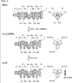
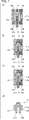
- FIG. 1 is a schematic diagram for explaining a manufacturing process of a conventional general forged crankshaft for a three-cylinder engine.
- the crankshaft 1 illustrated in FIG. 1 is mounted on a three-cylinder engine, and includes four journal portions J1 to J4, three pin portions P1 to P3, a front portion Fr, a flange portion Fl, and journal portions J1 to J1. It is composed of six crank arm portions (hereinafter also simply referred to as “arm portions”) A1 to A6 that connect J4 and pin portions P1 to P3, respectively.
- the crankshaft 1 includes first and second arm portions A1 and A2 and fifth and sixth arm portions A5 connected to the first and third pin portions P1 and P3 at both ends of the six arm portions A1 to A6.
- A6 is a 3-cylinder-four-counterweight crankshaft having a balance weight.
- the third and fourth arm portions A3 and A4 connected to the central second pin portion P2 have an oval shape because they do not have a balance weight.
- the reference numerals are “J” for the journal portion, “P” for the pin portion, and “A” for the arm portion.
- the arm part which has a balance weight is also called an arm part with a weight.
- the arm portion having no balance weight is also referred to as an unweighted arm portion or an oval arm portion.
- the forged crankshaft 1 is manufactured as follows. First, the billet 2 shown in FIG. 1A cut in advance to a predetermined length is heated by a heating furnace, and then roll forming is performed. In the roll forming step, for example, the billet 2 is rolled with a perforated roll and the volume thereof is distributed in the longitudinal direction while being drawn, thereby forming the roll rough ground 103 as an intermediate material (see FIG. 1B). Next, in the bending process, the roll rough ground 103 obtained by roll forming is partially pressed down from the direction perpendicular to the longitudinal direction to distribute its volume, and a bent rough ground 104 as a further intermediate material is formed. (See FIG. 1 (c)).
- the bent rough ground 104 obtained by bending is press-forged using a pair of upper and lower dies, and a forged material 105 in which the approximate shape of the crankshaft (final forged product) is formed is obtained. Molding is performed (see FIG. 1D). Further, in the finish punching process, a rough forging material 105 obtained by roughing is provided, the rough forging material 105 is press forged using a pair of upper and lower dies, and a shape that matches the crankshaft is formed. The material 106 is formed (see FIG. 1 (e)). At the time of roughing and finishing, surplus material flows out as burrs from between the split surfaces of the molds facing each other. For this reason, the rough forged material 105 and the finished forged material 106 have large burrs 105a and 106a around the shaped crankshaft.
- the burrs 106a are punched and removed by a blade tool while holding the finished forged material 106 with the burrs 106a obtained by finish punching with a mold from above and below. Thereby, as shown in FIG.1 (f), the forge crankshaft 1 is obtained.
- the main parts of the forged crankshaft 1 from which burrs have been removed for example, the shaft portion such as the journal portion J, the pin portion P, the front portion Fr, the flange portion Fl, or the like, or the arm portion A in some cases
- the forged crankshaft 1 is manufactured.
- Patent Document 1 Japanese Patent Application Laid-Open No. 2008-155275 (Patent Document 1) and Japanese Patent Application Laid-Open No. 2011-161696 (Patent Document 2) manufacture a crankshaft in which a journal portion and a pin portion are formed, and an arm portion is also formed as it is.
- the technology to do is disclosed.
- a stepped round bar in which portions corresponding to a journal portion and a pin portion of a crankshaft are individually constricted is used as a material.
- interposes a pin part equivalent part is each hold
- a simple round bar is used as a material. Then, one of the ends of the round bar material is held by a fixed type and the other is held by a movable type, the journal part of the round bar material is journal type, and the pin part is pin type. Retain each. From this state, the movable die, the journal die and the pin die are moved in the axial direction toward the fixed die to give the round bar material a compressive deformation. Simultaneously with this deformation application, the pin mold is moved in the eccentric direction perpendicular to the axial direction, and the portion corresponding to the pin portion is eccentric.
- the arm portion is a portion corresponding to the pin portion of the round bar material and free expansion in a direction perpendicular to the axial direction accompanying the axial deformation of the round bar material. It is shaped by the tensile deformation accompanying the eccentric movement. For this reason, the contour shape of the arm portion tends to be indefinite, and dimensional accuracy cannot be ensured.
- the present invention has been made in view of the above problems.
- the object of the present invention is to produce a forged crankshaft for a three-cylinder engine with a good yield and to finish the final shape in the manufacturing process of the forged crankshaft in order to produce it with high dimensional accuracy regardless of its shape. It is an object of the present invention to provide a molding apparatus used for molding a finish punching material to be used for finishing punching on the premise of performing punching. Another object of the present invention is to provide a manufacturing method capable of manufacturing a forged crankshaft for a three-cylinder engine with high yield and high dimensional accuracy regardless of its shape.
- a molding apparatus is an apparatus for molding a finishing material to be used for finishing punching for shaping the final shape of a forged crankshaft from a rough material in the process of manufacturing a forged crankshaft for a three-cylinder engine. is there.
- the forged crankshaft does not have balance weights in the third and fourth crank arm portions connected to the central second pin portion, and has balance weights in the remaining crank arm portions.
- the crude material is Coarse journal parts having the same axial length as each journal part of the forged crankshaft, Coarse pin portions having the same axial length as each pin portion of the forged crankshaft, Corresponding to the third and fourth crank arm portions of the forged crankshaft, third and fourth coarse crank arm portions having the same axial thickness as the crank arm portion; Corresponding to the weighted crank arm portion having the balance weight of the forged crankshaft, the weighted coarse crank arm portion is thicker in the axial direction than the crank arm portion.
- the apparatus for forming a finishing material for a forged crankshaft for a three-cylinder engine according to the present embodiment further includes the following configuration (1) or (2).
- the amount of eccentricity of the rough pin portion of the raw material in the direction perpendicular to the axial direction is smaller than the amount of eccentricity of the pin portion of the forged crankshaft.
- the molding apparatus includes the following reference pin type, movable pin type, fixed journal type, and movable journal type.
- the reference pin type is disposed at the position of the second rough pin portion, is addressed to the rough pin portion, and is in contact with the side surfaces of the third and fourth rough crank arm portions connected to the rough pin portion while being axially Is restricted and moves in a direction perpendicular to the axial direction.
- the movable pin type is arranged at the position of each of the first and third rough pin portions at both ends, is addressed to each of the rough pin portions, and each contacts the side surface of the rough crank arm portion connected to the rough pin portion. However, it moves in an axial direction toward the reference pin mold and a direction perpendicular to the axial direction.
- the fixed journal type is disposed at the position of the coarse journal portion connected to the third and fourth coarse crank arm portions, and holds and holds the coarse journal portion individually from the direction perpendicular to the axial direction. The axial movement is restricted while contacting the side surface of the fourth coarse crank arm portion.
- the movable journal type is disposed at each position of the coarse journal portion other than the coarse journal portion connected to the third and fourth coarse crank arm portions, and holds and holds the coarse journal portion individually from a direction perpendicular to the axial direction. Each moves in the axial direction toward the reference pin type while contacting the side surface of the coarse crank arm portion connected to the coarse journal portion.
- the molding apparatus sandwiches and holds the coarse journal part between the fixed journal type and the movable journal type, and moves the movable journal type in the axial direction from the state where the reference pin type and the movable pin type are assigned to the coarse pin part.
- the movable pin mold is moved in the direction perpendicular to the axial direction, and at the same time, the reference pin mold is moved in the direction perpendicular to the axial direction.
- the rough crank arm portion with weight is clamped in the axial direction to reduce its thickness to the thickness of the crank arm portion with weight of the forged crankshaft, and the rough pin portion is pressed in a direction perpendicular to the axial direction.
- the eccentric amount is increased to the eccentric amount of the pin portion of the forged crankshaft.
- the reference pin mold and the movable pin mold are disposed outside the rough pin portion opposite to the side to which the reference pin mold and the movable pin mold are assigned.
- An auxiliary pin type, and the movable journal type, the movable pin type, and the auxiliary pin type paired with the movable pin type in the axial direction, the movable journal type and the reference pin After the gap between the mold, the movable pin mold, and the auxiliary pin mold is closed, the rough pin portion that is pressed and deformed reaches the auxiliary pin mold in a direction perpendicular to the axial direction of the movable pin mold. It is preferable that the movement is controlled.
- the moving distance in the direction perpendicular to the axial direction of the movable pin type is 90% or less of the total moving distance, and then the movement in the direction perpendicular to the axial direction of the movable pin type is completed. It is preferable.
- the reference pin mold, the movable pin mold, the fixed journal mold, and the movable journal mold may be a press machine that can be reduced in a direction along a direction perpendicular to the axial direction.
- the fixed journal mold and the movable journal mold sandwich and hold the coarse journal part as the press machine is pressed, and the reference pin mold and the movable pin mold are addressed to the coarse pin part.
- the movable journal mold is individually moved in the axial direction by the wedge mechanism as the press machine continues to be reduced.
- the movable pin mold is individually moved along with the movement of the movable journal mold. It can be set as the structure which moves to an axial direction.
- the wedge angle of the wedge mechanism is different from each other in each of the movable journal molds. Furthermore, it is preferable that the reference pin type and the movable pin type are connected to a hydraulic cylinder and moved in a direction perpendicular to the axial direction by driving the hydraulic cylinder.
- the first and third coarse pin portions at both ends of the coarse material have eccentric amounts in directions perpendicular to the axial direction opposite to each other, and are more than ⁇ 3 / 2 of the eccentric amount of the pin portion of the forged crankshaft. small.
- the second coarse pin portion at the center of the coarse material has zero eccentricity in the direction perpendicular to the axial direction, or the direction of the pin portion of the forged crankshaft is perpendicular to the eccentric direction of the first and third coarse pin portions. It is the same as the amount of eccentricity.
- the forming apparatus includes the following reference pin type, movable pin type, and journal type.
- the reference pin type is disposed at the position of the second rough pin portion, is addressed to the rough pin portion, and is in contact with the side surfaces of the third and fourth rough crank arm portions connected to the rough pin portion while being axially Is restricted from moving.
- the movable pin type is arranged at the position of each of the first and third coarse pin portions, is assigned to each of the coarse pin portions, and each is in contact with the side surface of the coarse crank arm portion connected to the coarse pin portion. , Move in the axial direction toward the reference pin mold and in the direction perpendicular to the axial direction.
- the fixed journal type is disposed at the position of the coarse journal portion connected to the third and fourth coarse crank arm portions, and holds and holds the coarse journal portion individually from the direction perpendicular to the axial direction.
- the axial movement is restricted while contacting the side surface of the fourth coarse crank arm portion.
- the movable journal type is disposed at each position of the coarse journal portion other than the coarse journal portion connected to the third and fourth coarse crank arm portions, and holds and holds the coarse journal portion individually from a direction perpendicular to the axial direction. Each moves in the axial direction toward the reference pin type while contacting the side surface of the coarse crank arm portion connected to the coarse journal portion.
- the molding apparatus sandwiches and holds the coarse journal part between the fixed journal type and the movable journal type, and moves the movable journal type in the axial direction from the state where the reference pin type and the movable pin type are assigned to the coarse pin part.
- the movable pin mold is moved in the direction perpendicular to the axial direction while moving in the axial direction.
- the rough crank arm portion with weight is clamped in the axial direction to reduce its thickness to the thickness of the crank arm portion with weight of the forged crank shaft, and the first and third rough pin portions are perpendicular to the axial direction.
- a manufacturing method is a method for manufacturing a forged crankshaft for a three-cylinder engine, and includes any one of the following configurations (3) to (6).
- the manufacturing method includes a series of steps including a first preforming step, a second preforming step, and a finish punching step described below.
- a crude material to be provided to the molding apparatus (1) is modeled.
- the first and third coarse pin portions at both ends of the coarse material have the same amount of eccentricity in the direction perpendicular to the axial direction as the ⁇ 3 / 2 of the eccentric amount of the pin portion of the forged crankshaft.
- the second coarse pin portion at the center of the coarse material has an eccentric amount in a direction perpendicular to the axial direction perpendicular to the eccentric direction of the first and third coarse pin portions, and the eccentric amount of the pin portion of the forged crankshaft. Smaller than.
- the finishing material is molded using the molding apparatus (1).
- the finish punching material is formed with the final shape of the forged crankshaft including the pin arrangement angle.
- the finish punching material is finish punched to form a finish material in which the final shape of the forged crankshaft is formed including the pin portion arrangement angle.
- the manufacturing method includes a series of steps including a first preforming step, a second preforming step, a finish punching step, and a twisting step described below.
- a crude material to be provided to the molding apparatus (1) is modeled.
- the first and third coarse pin portions at both ends of the coarse material have an eccentric amount in a direction perpendicular to the axial direction that is smaller than the eccentric amount of the pin portion of the forged crankshaft.
- the second coarse pin portion at the center of the coarse material has an eccentric amount in a direction perpendicular to the axial direction opposite to the eccentric direction of the first and third coarse pin portions, and the eccentric amount of the pin portion of the forged crankshaft. Is also small.
- the finishing material is molded using the molding apparatus (1).
- the final shape of the forged crankshaft is formed on the finishing material except for the pin portion arrangement angle.
- the finish punching process the finish punching material is finish punched, and a finish material in which the final shape of the forged crankshaft is formed is formed except for the arrangement angle of the pin portion.
- the arrangement angle of the pin portion of the finishing material is adjusted to the arrangement angle of the pin portion of the forged crankshaft.
- the manufacturing method includes a series of steps including a first preforming step, a second preforming step, and a finish punching step described below.
- a rough material to be provided to the molding apparatus (2) is modeled.
- the first and third rough pin portions at both ends of the rough material have eccentric amounts in directions perpendicular to the axial direction that are opposite to each other and less than ⁇ 3 / 2 of the eccentric amount of the pin portion of the forged crankshaft.
- the second coarse pin portion at the center of the coarse material has zero eccentricity in the direction perpendicular to the axial direction.
- the finishing material is formed using the forming device (2).
- the first and third rough pin portions at both ends of the finish punching material have the same amount of eccentricity in the direction perpendicular to the axial direction as ⁇ 3 / 2 of the eccentric amount of the pin portion of the forged crankshaft. is there.
- the second coarse pin portion at the center of the finishing material remains the same as the coarse material in the amount of eccentricity in the direction perpendicular to the axial direction.
- the finish punching material is finish punched in a state where the first and third rough pin portions at both ends are in a horizontal posture, and all the rough pin portions are pressed in a direction perpendicular to the axial direction, A finishing material in which the final shape of the forged crankshaft is formed including the arrangement angle of the parts is formed.
- the manufacturing method includes a series of steps including a first preforming step, a second preforming step, and a finish punching step described below.
- a rough material to be provided to the molding apparatus (2) is modeled.
- the first and third rough pin portions at both ends of the rough material have eccentric amounts in directions perpendicular to the axial direction that are opposite to each other and less than ⁇ 3 / 2 of the eccentric amount of the pin portion of the forged crankshaft.
- the second coarse pin portion at the center of the coarse material has an eccentric amount in a direction perpendicular to the axial direction perpendicular to the eccentric direction of the first and third coarse pin portions, and the eccentric amount of the pin portion of the forged crankshaft. Is the same.
- the finishing material is formed using the forming device (2).
- the first and third rough pin portions at both ends of the finish punching material have the same amount of eccentricity in the direction perpendicular to the axial direction as ⁇ 3 / 2 of the eccentric amount of the pin portion of the forged crankshaft. is there.
- the second coarse pin portion at the center of the finishing material remains the same as the coarse material in the amount of eccentricity in the direction perpendicular to the axial direction.
- the finishing material is finished in a state where the first and third rough pin portions at both ends are in a horizontal posture, and the first and third rough pin portions are pressed in a direction perpendicular to the axial direction. Then, a finishing material in which the final shape of the forged crankshaft including the arrangement angle of the pin portion is formed is formed.
- the forged crank for a three-cylinder engine having a thin arm portion, even if it is a weighted arm portion, from a rough material without burrs. It is possible to form a finishing material that does not have burrs and has a shape that roughly matches the shape of the shaft. If such a burr-free finish punching material is finished, some burrs are generated, but the final shape of the forged crankshaft including the contour shape of the arm portion can be formed. Accordingly, a forged crankshaft for a three-cylinder engine can be manufactured with high yield and high dimensional accuracy regardless of its shape.
- FIG. 1 is a schematic diagram for explaining a manufacturing process of a conventional general forged crankshaft for a three-cylinder engine.
- FIG. 2 is a diagram schematically showing each shape of a raw material to be molded by a molding apparatus, a formed finishing material, and a finishing material after finishing in the manufacturing method of the first embodiment.
- Drawing 3 is a mimetic diagram showing a manufacturing process of a forge crankshaft in a 1st embodiment.
- FIG. 4 is a longitudinal sectional view showing the configuration of the molding apparatus in the first embodiment.
- FIG. 5A is a longitudinal sectional view for explaining a method of forming a finishing material by the forming apparatus of the first embodiment shown in FIG. 4, and shows a state in the initial stage of forming.
- FIG. 5A is a longitudinal sectional view for explaining a method of forming a finishing material by the forming apparatus of the first embodiment shown in FIG. 4, and shows a state in the initial stage of forming.
- FIG. 1 is a schematic diagram for
- FIG. 5B is a longitudinal sectional view for explaining a method of forming a finishing material by the forming apparatus of the first embodiment shown in FIG. 4 and shows a state when the forming is completed.
- FIG. 6 is a diagram for explaining a situation in which biting occurs when the finish punching material is formed by the forming apparatus.
- FIG. 7 is a diagram for explaining a situation when a countermeasure for biting is applied in forming a finishing material by a forming apparatus.
- FIG. 8 shows each shape of a rough material to be molded by a molding apparatus, a finished finishing material, a finishing material after finishing, and a torsion finishing material after torsion molding in the manufacturing method of the second embodiment.
- FIG. 9 is a schematic diagram illustrating a manufacturing process of a forged crankshaft in the second embodiment.
- FIG. 10 is a longitudinal sectional view showing the configuration of the molding apparatus in the second embodiment.
- FIG. 11A is a longitudinal sectional view for explaining a method of forming a finishing material by the forming apparatus of the second embodiment shown in FIG. 10, and shows a state in the initial stage of forming.
- FIG. 11B is a longitudinal sectional view for explaining a method of forming a finishing material by the forming apparatus of the second embodiment shown in FIG. 10, and shows a state when the forming is completed.
- FIG. 11A is a longitudinal sectional view for explaining a method of forming a finishing material by the forming apparatus of the second embodiment shown in FIG. 10, and shows a state when the forming is completed.
- FIG. 11B is a longitudinal sectional view for explaining a method of forming a finishing material by the forming apparatus of the second embodiment shown in FIG. 10, and shows a state when the forming is
- FIG. 12 is a diagram schematically showing each shape of a raw material to be molded by the molding apparatus, a finished finishing material, and a finishing material after finishing punching in the manufacturing method of the third embodiment.
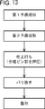
- FIG. 13 is a schematic diagram illustrating a forged crankshaft manufacturing process according to the third embodiment.
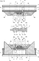
- FIG. 14 is a longitudinal sectional view showing the configuration of the molding apparatus in the third embodiment.
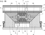
- FIG. 15A is a longitudinal sectional view for explaining a method of forming a finish punching material by the forming apparatus of the third embodiment shown in FIG. 14, and shows a state in the initial stage of forming.
- FIG. 15B is a longitudinal sectional view for explaining a method of forming a finishing material by the forming apparatus of the third embodiment shown in FIG.
- FIG. 16 is a diagram schematically showing each shape of a raw material to be molded by the molding apparatus, a formed finishing material, and a finishing material after finishing in the manufacturing method of the fourth embodiment.
- FIG. 17 is a schematic diagram illustrating a forged crankshaft manufacturing process according to the fourth embodiment.
- the forming apparatus of the present invention is used to form a finish punching material to be used for finishing punching from a raw material in a pre-finishing process.
- the embodiment of the forging crankshaft forming apparatus for a forged crankshaft for a three-cylinder engine according to the present invention and a method for producing a forged crankshaft for a three-cylinder engine including a pre-forming step using the same are described in detail. To do.
- FIG. 2 is a diagram illustrating a raw material to be molded by a molding apparatus, a formed finishing material, and a finishing material after finishing punching in the manufacturing method of the first embodiment. It is a figure which shows typically each shape of.
- FIG. 2 shows a situation in the case of manufacturing a crankshaft of a three-cylinder / four-counterweight.
- FIG. 2 shows a plan view showing the appearance and a layout diagram of the pin portions when viewed along the axial direction in order to facilitate understanding of the shape of each stage.
- the coarse material 4 of the first embodiment has a rough crankshaft shape as a whole while relying on the shape of the forged crankshaft 1 of the three-cylinder / four-piece counterweight shown in FIG. 1 (f). is there.
- the coarse material 4 connects the four coarse journal portions J1a to J4a, the three coarse pin portions P1a to P3a, the coarse front portion Fra, the coarse flange portion Fla, and the coarse journal portions J1a to J4a and the coarse pin portions P1a to P3a.
- Six coarse crank arm portions (hereinafter also simply referred to as “rough arm portions”) A1a to A6a.
- the third and fourth coarse arm portions A3a and A4a connected to the second coarse pin portion P2a at the center do not have a balance weight, and thus have an oval shape.
- the coarse material 4 has no burrs.
- the symbols are “Ja” for the coarse journal portion and “Ja” for the coarse pin portion. “Pa” and “Aa” for the rough arm.
- the first, second, fifth, and sixth coarse arm portions A1a, A2a, A5a, and A6a having balance weights are also referred to as weighted coarse arm portions Aa.
- the third and fourth coarse arm portions A3a and A4a having no balance weight are also referred to as a no-weight coarse arm portion Aa or an oval coarse arm portion Aa.
- the finish punching material 5 of the first embodiment is formed from the above-mentioned rough material 4 by a molding device, which will be described in detail later.
- the finishing material 5 includes four rough journal portions J1b to J4b, three rough pin portions P1b to P3b, a rough front portion Frb, a rough flange portion Flb, a rough journal portion J1b to J4b, and a rough pin portion P1b to P3b.
- Six coarse crank arm portions (hereinafter also simply referred to as “rough arm portions”) A1b to A6b connected to each other.
- the third and fourth coarse arm portions A3b, A4b connected to the second coarse pin portion P2b at the center do not have a balance weight, and thus have an oval shape.
- the finishing material 5 has no burrs.
- the reference numeral is “Jb” for the rough journal portion, and the rough pin portion.
- the first, second, fifth, and sixth coarse arm portions A1b, A2b, A5b, and A6b having balance weights are also referred to as weighted coarse arm portions Ab.
- the third and fourth coarse arm portions A3b and A4b that do not have a balance weight are also referred to as a weightless coarse arm portion Ab or an oval coarse arm portion Ab.
- the finishing material 6 of the first embodiment is obtained by finishing the above-described finishing material 5.
- the finishing material 6 includes four journal portions J1c to J4c, three pin portions P1c to P3c, a front portion Frc, a flange portion Flc, and six crank arm portions that connect the journal portions J1c to J4c and the pin portions P1c to P3c, respectively. (Hereinafter also simply referred to as “arm portion”) A1c to A6c. Since the third and fourth arm portions A3c, A4c connected to the central second pin portion P2c do not have a balance weight, they have an oval shape.
- journal parts J1c to J4c, the pin parts P1c to P3c, and the arm parts A1c to A6c of the finishing material 6 are collectively referred to, the reference numerals are “Jc” for the journal part, “Pc” for the pin part, and the arm part. Is written as “Ac”.
- the first, second, fifth, and sixth arm portions A1c, A2c, A5c, and A6c having balance weights are also referred to as weighted arm portions Ac.
- the third and fourth arm portions A3c and A4c having no balance weight are also referred to as no-weight arm portion Ac or oval arm portion Ac.
- the shape of the finishing material 6 matches the shape of the crankshaft (final forged product) including the arrangement angle of the pin portion Pc, and corresponds to the forged crankshaft 1 shown in FIG. That is, the journal portion Jc of the finishing material 6 has the same axial length as the journal portion J of the final shape forged crankshaft.
- the pin portion Pc of the finishing material 6 has the same axial length as the pin portion P of the final shape forged crankshaft. Further, the pin portion Pc of the finishing material 6 has the same amount of eccentricity in the direction perpendicular to the axial direction and the same arrangement angle of 120 ° with respect to the pin portion P of the final shape forged crankshaft. Is arranged.
- the arm portion Ac of the finishing material 6 has the same axial thickness as the arm portion A of the final shape forged crankshaft.
- the shape of the finishing material 5 is almost the same as the shape of the finishing material 6, and corresponds to the portion excluding the burr 105a of the rough forging material 105 shown in FIG. That is, the coarse journal portion Jb of the finishing material 5 has the same axial length as the journal portion J of the final shape forged crankshaft (the journal portion Jc of the finishing material 6).
- the rough pin portion Pb of the finishing material 5 has the same axial length as the pin portion P of the final shape forged crankshaft (the pin portion Pc of the finishing material 6).
- the pin portion Pb of the finish punching material 5 has the same eccentricity in the direction perpendicular to the axial direction with respect to the pin portion P of the final shape forged crankshaft, and the arrangement angle is also the same 120 °. It is arranged at the position.
- the rough arm portion Ab of the finishing material 5 has the same axial thickness as the arm portion A of the final shape forged crankshaft (the arm portion Ac of the finishing material 6).
- the coarse journal portion Ja of the coarse material 4 has the same axial length as the coarse journal portion Jb of the finishing material 5, that is, the journal portion J of the forged crankshaft (the journal portion Jc of the finish material 6). It is.
- the coarse pin portion Pa of the coarse material 4 has the same axial length as the coarse pin portion Pb of the finish punching material 5, that is, the pin portion P of the forged crankshaft (the pin portion Pc of the finish material 6). The amount of eccentricity is smaller than the rough pin portion Pb of the finish punching material 5.
- the eccentric amounts of the first and third coarse pin portions P1a and P3a at both ends are in opposite directions to the eccentric amount of the pin portion P of the forged crankshaft. Is the same as ⁇ 3 / 2.
- the eccentric amount of the center second coarse pin portion P2a is 1 / of the eccentric amount of the pin portion P of the forged crankshaft in a direction perpendicular to the eccentric direction of the first and third coarse pin portions P1a, P3a. It is about 2.
- the coarse arm portions Aa of the coarse material 4 correspond to the finishing materials corresponding to each. Thickness in the axial direction is thicker than the weighted rough arm portion Ab 5, that is, the weighted arm portion A of the forged crankshaft (the armed portion Ac of the finishing material 6).
- the oval coarse arm portion Aa (third and fourth coarse arm portions A3a, A4a) of the coarse material 4 is the oval coarse arm portion Ab of the finishing material 5 corresponding to each, that is, the oval shape of the forged crankshaft.
- the thickness in the axial direction is the same as the shape arm portion A (the oval arm portion Ac of the finishing material 6).
- the rough material 4 has a longer overall length than the finish punching material 5 (final shape forged crankshaft and finishing material 6) by the thicker weight of the rough arm portion Aa, and the rough pin portion Pa.
- the eccentricity of is small.
- the coarse material 4 has a relatively gentle crankshaft shape.
- the finish punching material 5 is slightly thinner than the forged crankshaft and the finishing material 6 in the final shape, and the coarse journal portion Jb and the coarse pin portion Pb are correspondingly thin.
- the axial length of is slightly larger. This is because it is easy to accommodate the finishing material 5 in the mold at the time of finishing and prevent the occurrence of galling. Accordingly, the axial length of the coarse journal portion Ja and the coarse pin portion Pa is also slightly larger in the coarse material 4 than in the final shape forged crankshaft and finish material 6.
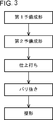
- FIG. 3 is a schematic diagram showing a manufacturing process of the forged crankshaft in the first embodiment.
- the forged crankshaft manufacturing method according to the first embodiment includes steps of first preforming, second preforming, and finish punching, and each step of deburring and shaping as necessary. including.
- the first pre-molding step is a step of modeling the above-described rough material 4.
- a round billet having a round cross section is used as a raw material, and the round billet is heated by an induction heating furnace or a gas atmosphere heating furnace and then subjected to a preforming process.
- a round billet is drawn and rolled by a perforated roll and its volume is distributed in the longitudinal direction, and the roll waste obtained thereby is partially pressed down from the direction perpendicular to the longitudinal direction to obtain its volume. Repeat the bending to distribute.
- the rough material 4 can be modeled.
- the rough material 4 can be formed using the techniques disclosed in Patent Documents 1 and 2.
- the second pre-molding step is a step of molding the finishing material 5 described above.
- processing is performed using the molding apparatus shown in FIG. Thereby, the finishing material 5 in which the final shape of the forged crankshaft including the arrangement angle of the pin portion is formed can be formed from the rough material 4.
- Finishing process is a process for obtaining the finishing material 6 described above.
- the finish punching material 5 is provided and press forged using a pair of upper and lower dies. Thereby, it is possible to obtain the finishing material 6 having a shape that matches the crankshaft, in which the final shape of the forged crankshaft is formed including the arrangement angle of the pin portion.
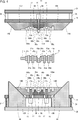
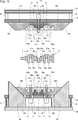
- FIG. 4 is a longitudinal sectional view showing the configuration of the forming apparatus in the first embodiment.
- FIG. 4 exemplifies a molding apparatus for producing a crankshaft of a three-cylinder / four-counter weight, that is, a molding apparatus for molding the finishing material 5 from the raw material 4 shown in FIG.
- the first and third rough pin portions are actually located either on the front side of the paper and on the other side, but for the sake of convenience, they are on the same plane. Illustrated above.
- the molding apparatus uses a press machine, and has a fixed lower hard plate 20 serving as a foundation and an upper hard plate 21 that descends as the ram of the press machine is driven.
- a lower mold support base 22 is elastically supported via an elastic member 24 directly above the lower hard plate 20.
- the lower mold support base 22 is allowed to move in the vertical direction.
- a disc spring, a coil spring, an air spring or the like can be applied, and a hydraulic spring system can also be applied.
- An upper mold support base 23 is fixed directly below the upper hard plate 21 via a support column 25. The upper mold support 23 is lowered integrally with the upper hard plate 21 by driving of a press machine (ram).
- the rough material 4 is placed in the mold in a posture in which the first and third rough pin portions P1a and P3a are horizontally disposed and the second rough pin portion P2a is disposed downward in the vertical direction. Accommodate.
- the rough material 4 in this posture is formed into a finishing material.
- the lower mold support base 22 and the upper mold support base 23 are divided along the axial direction of the coarse material 4, and are respectively fixed journal molds 9U, 9B, movable journal molds 10U, 10B, the reference pin type 11 and the auxiliary pin type 13, and the movable pin type 12 and the auxiliary pin type 13 are attached.
- the reference pin mold 11 and the auxiliary pin mold 13 that are paired up and down are arranged at the position of the center second coarse pin portion P2a of the coarse pin portion Pa in the coarse material 4, and each of the upper and lower portions is an upper metal. It is attached to the mold support 23 and the lower mold support 22.
- the reference pin mold 11 of the first embodiment is disposed on the side opposite to the side that is the normal position of the second rough pin portion P2a.
- the other auxiliary pin mold 13 is arranged outside the second rough pin portion P2a on the side that is the normal position. For example, in the position of the 2nd rough pin part P2a, arrangement
- the reference pin mold 11 and the auxiliary pin mold 13 are restrained from moving in the axial direction on the upper mold support base 23 and the lower mold support base 22 in both the upper and lower sides. Only the reference pin mold 11 is allowed to move in a direction perpendicular to the axial direction and toward the normal position of the coarse pin portion Pa (downward direction in FIG. 4).
- the reference pin mold 11 and the auxiliary pin mold 13 are formed with semi-cylindrical engraved portions 11a and 13a, respectively.
- the lengths of the engraved portions 11a and 13a are the same as the length in the axial direction of the second rough pin portion P2b in the finishing material 5.
- the engraved portion 11a is addressed to the second rough pin portion P2a by the lowering of the upper die support base 23 accompanying the drive of the press machine, that is, the press machine is pressed down.
- both side surfaces of the reference pin mold 11 come into contact with the side surfaces of the third and fourth rough arm portions A3a, A4a connected to the second rough pin portion P2a on the second rough pin portion P2a side.
- the movable pin mold 12 and the auxiliary pin mold 13 that form a pair in the upper and lower directions are arranged at the positions of the first and third coarse pin portions P1a and P3a, respectively, and the upper and lower mold support bases 23 and the lower mold support respectively. Attached to the base 22.
- the movable pin mold 12 of the first embodiment is disposed on the side opposite to the side that is the normal position of the coarse pin portion Pa.
- the other auxiliary pin mold 13 is disposed outside the rough pin portion Pa on the side that is the normal position.
- the regular position of the 1st rough pin part P1a is an upper side.
- the movable pin mold 12 is attached to the lower mold support base 22, and the auxiliary pin mold 13 that is paired with the movable pin mold 12 is attached to the upper mold support base 23.
- the movable pin mold 12 and the auxiliary pin mold 13 are allowed to move in the axial direction toward the reference pin mold 11 on the lower mold support base 22 and the upper mold support base 23 both in the upper and lower directions. Is done. Only the movable pin type 12 is allowed to move in a direction perpendicular to the axial direction and toward the normal position of the coarse pin portion Pa (upward direction in FIG. 4).
- the movable pin mold 12 and the auxiliary pin mold 13 are formed with semi-cylindrical engraved portions 12a and 13a, respectively.
- the lengths of the engraved portions 12a and 13a are the same as the lengths in the axial direction of the rough pin portions Pb in the finishing material 5 for finishing.
- the fixed journal molds 9U and 9B are coarse journal portions Ja (second and third coarse journal portions J2a and J3a) connected to the oval coarse arm portion Aa (third and fourth coarse arm portions A3a and A4a) of the coarse material 4.
- the upper and lower mold support bases 23 and 22 are attached to the upper mold support base 23 and the lower mold support base 22, respectively.
- the fixed journal molds 9U and 9B are completely fixed to the upper mold support base 23 and the lower mold support base 22 in both the upper and lower sides, and the movement in the axial direction is restricted.
- the fixed journal molds 9U and 9B include semi-cylindrical first engraved portions 9Ua and 9Ba, and second engraved portions 9Ub adjacent to the front and rear (left and right in FIG. 4) of the first engraved portions 9Ua and 9Ba, respectively. 9Bb and third engraved portions 9Uc and 9Bc are formed.
- the lengths of the first engraved portions 9Ua and 9Ba are the same as the axial lengths of the coarse journal portions Jb (second and third coarse journal portions J2b and J3b) in the finish punching material 5.
- the lengths of the second engraved portions 9Ub and 9Bb are the thicknesses in the axial direction of the coarse arm portions Ab with weights (second and fifth coarse arm portions A2b and A5b) connected to the coarse journal portion Jb in the finishing material 5.
- the lengths of the third engraved portions 9Uc and 9Bc are the thicknesses in the axial direction of the oval coarse arm portion Ab (the third and fourth coarse arm portions A3b and A4b) connected to the coarse journal portion Jb in the finishing material 5. The same.
- the fixed journal molds 9U and 9B hold the respective rough journal portions Ja respectively corresponding to each of the first engraved portions 9Ua and 9Ba by being pressed by the press machine.
- the surfaces of the second engraved portions 9Ub and 9Bb and the third engraved portions 9Uc and 9Bc on the first engraved portions 9Ua and 9Ba side correspond to the corresponding coarse journal portions Ja. It contacts the side surface of each coarse journal portion Ja side in the connected coarse arm portion Aa with weight and the oval coarse arm portion Aa.
- the movable journal molds 10U and 10B are provided with coarse journal portions Ja (second and third coarse journal portions J2a and J3a) connected to the oval coarse arm portions Aa (third and fourth coarse arm portions A3a and A4a) of the coarse material 4.
- the upper and lower portions are attached to the upper mold support base 23 and the lower mold support base 22, respectively.
- the movable journal molds 10U and 10B are allowed to move in the axial direction toward the reference pin mold 11 on the upper mold support base 23 and the lower mold support base 22 both in the upper and lower directions.
- the movable journal molds 10U and 10B include semi-cylindrical first engraved portions 10Ua and 10Ba, and second engraved portions 10Ub adjacent to the front and rear (left and right in FIG. 4) of the first engraved portions 10Ua and 10Ba, respectively. 10Bb is formed.
- the lengths of the first engraved portions 10Ua and 10Ba are the same as the axial lengths of the coarse journal portions Jb (first and fourth coarse journal portions J1b and J4b) in the finish punching material 5.
- the lengths of the second engraved portions 10Ub and 10Bb are the thicknesses in the axial direction of the coarse arm portions Ab with weights (the first and sixth coarse arm portions A1b and A6b) connected to the coarse journal portion Jb in the finishing material 5. The same.
- the movable journal molds 10U and 10B sandwich and hold the respective coarse journal portions Ja corresponding to each of the first engraved portions 10Ua and 10Ba from above and below by the press machine.
- the movable journal molds 10U and 10B are provided in the coarse arm portions Aa with weights where the surfaces of the second engraved portions 10Ub and 10Bb on the first engraved portions 10Ua and 10Ba are connected to the corresponding coarse journal portions Ja. It contacts the side surface of each coarse journal portion Ja side.
- the reference pin mold 11 and the movable pin mold 12 are engraved portions 11a, 12a to each rough pin portion Pa by the press machine, and both side surfaces of the reference pin mold 11 and the movable pin mold 12 are It contacts the side surface of each rough pin portion Pa side in the rough arm portion Aa connected to each rough pin portion Pa.
- the end surfaces of the movable journal molds 10U and 10B arranged at the positions of the first and fourth coarse journal portions J1a and J4a at both ends are inclined surfaces 14U and 14B.
- wedges are individually provided corresponding to the positions of the inclined surfaces 14U and 14B of the movable journal molds 10U and 10B of the first and fourth coarse journal portions J1a and J4a. 26 is erected. Each wedge 26 protrudes upward through the lower mold support base 22.
- the inclined surface 14B of the lower movable journal mold 10B is in contact with the inclined surface of the wedge 26 in the initial state.
- the inclined surface 14U of the upper movable journal mold 10U comes into contact with the inclined surface of the wedge 26 by the pressure of the press machine.
- the upper movable journal mold 10U is pushed down integrally with the lower movable journal mold 10B.
- the movable journal molds 10U and 10B of the first and fourth coarse journal portions J1a and J4a have the inclined surfaces 14U and 14B slide along the inclined surface of the wedge 26 in both the upper and lower directions. It moves in the axial direction toward the reference pin mold 11 of the second rough pin portion P2a.
- the movable journal molds 10U and 10B can be individually moved in the axial direction by a wedge mechanism.
- the movable pin mold 12 and the auxiliary pin mold 13 are pushed down together as the press machine continues to be reduced.
- the movable pin mold 12 and the auxiliary pin mold 13 become the reference pin mold 11 of the second rough pin portion P2a serving as a reference as the movable journal molds 10U and 10B move in the axial direction as described above. Move in the axial direction.
- the movement of the reference pin mold 11 and the movable pin mold 12 in the direction perpendicular to the axial direction is performed by driving the hydraulic cylinders 16 connected to the pin molds 11 and 12.
- the movement of the movable pin mold 12 and the auxiliary pin mold 13 in the axial direction is forced by using a wedge mechanism similar to the movable journal molds 10U and 10B, or using a separate mechanism such as a hydraulic cylinder or a servo motor. You may go to The auxiliary pin mold 13 may be integrated with one of a pair of adjacent movable journal molds 10U, 10B or one of the fixed journal molds 9U, 9B.
- each gap is secured between the movable journal molds 10U and 10B and the fixed journal molds 9U and 9B, which are individually linked in the axial direction, and the movable pin mold 12 and the auxiliary pin mold 13. This is because the movable journal molds 10U and 10B and the movable pin mold 12 and the auxiliary pin mold 13 are allowed to move in the axial direction.
- the size of each gap is the difference between the thickness of the coarse arm portion Ab with weight in the finishing material 5 and the thickness of the coarse arm portion Aa with weight in the coarse material 4.
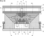
- FIG. 5A and 5B are longitudinal sectional views for explaining a method of forming a finishing material by the forming apparatus of the first embodiment shown in FIG. Among these drawings, FIG. 5A shows a state in the initial stage of molding, and FIG. 5B shows a state when the molding is completed.
- the raw material 4 is accommodated in the lower movable journal mold 10B, the fixed journal mold 9B, the movable pin mold 12 and the auxiliary pin mold 13 shown in FIG. 4, and the pressing of the press machine is started. Then, first, as shown in FIG. 5A, the upper movable journal mold 10U and the fixed journal mold 9U come into contact with the lower movable journal mold 10B and the fixed journal mold 9B, respectively.
- the coarse material 4 has each coarse journal portion Ja held from above and below by the movable journal molds 10U and 10B and the fixed journal molds 9U and 9B, and the reference pin mold 11 and the movable pin mold 12 are assigned to each coarse pin section Pa. It will be in a state of being broken. In this state, the movable journal molds 10U and 10B and the fixed journal molds 9U and 9B are in contact with the side surface of the coarse material section 4 on the coarse journal section Ja side of the coarse material 4, and the coarse pins in the respective coarse arm sections Aa. The reference pin mold 11 and the movable pin mold 12 are in contact with the side surface on the part Pa side. In this state, the inclined surfaces 14U and 14B of the movable journal molds 10U and 10B of the first and fourth coarse journal portions J1a and J4a are in contact with the inclined surface of the wedge 26.
- the gaps between the movable journal molds 10U and 10B and the fixed journal molds 9U and 9B and the movable pin mold 12 and the auxiliary pin mold 13 are gradually narrowed, and finally the gaps are eliminated.
- the coarse material 4 maintains the axial lengths of the coarse journal portion Ja and the coarse pin portion Pa by the movable journal types 10U and 10B, the fixed journal types 9U and 9B, the reference pin type 11 and the movable pin type 12.
- the weighted coarse arm portion Aa is pinched in the axial direction.
- the thickness of the coarse arm portion Aa with weight decreases to the thickness of the coarse arm portion Ab with weight of the finishing material 5 (see FIG. 5B).
- mold 11 and 12 presses the rough pin part Pa of the coarse raw material 4 in the direction orthogonal to an axial direction individually.
- the coarse pin portion Pa of the coarse material 4 is displaced in the vertical direction perpendicular to the axial direction, so that the amount of eccentricity increases to the amount of eccentricity of the coarse pin portion Pb of the finish punching material 5.
- the pin part Pb will also be in the state arrange
- the shape of the forged crankshaft (final forged product) for a three-cylinder engine where the thickness of the arm portion A is thin The finishing material 5 without burrs can be formed. If such a burr-free material 5 for finishing is used for finishing, a slight burr is generated, but a three-cylinder engine including the contour shape of the arm part and the arrangement angle of the pin part is included.
- the final shape of the forged crankshaft can be shaped. Accordingly, a forged crankshaft for a three-cylinder engine can be manufactured with high yield and high dimensional accuracy regardless of its shape.
- the inclined angles of the inclined surfaces 14U and 14B of the movable journal molds 10U and 10B of J4a and the inclined surface of the wedge 26 in contact with the inclined surfaces are opposite to each other with respect to the vertical plane.
- the reason why the wedge angle of the wedge mechanism for moving each movable journal mold 10U, 10B in the axial direction is different for each movable journal mold 10U, 10B is that the rough arm portion Aa with weight is clamped in the axial direction to obtain a thickness. This is because the deformation speed for reducing the above is constant for all the weighted coarse arm portions Aa.
- the rough material 4 used in the molding apparatus shown in FIGS. 4, 5A and 5B has a cross-sectional area of the rough journal portion Ja, which is the cutting of the rough journal portion Jb of the finish punching material 5, that is, the journal portion J of the forged crankshaft. It is equal to or larger than the area.
- the cross-sectional area of the rough pin portion Pa of the rough material 4 is the same as or larger than the cross-sectional area of the rough pin portion Pb of the finish punching material 5, that is, the pin portion P of the forged crankshaft.
- the cross-sectional area of the coarse journal portion Ja of the coarse material 4 is larger than the cross-sectional area of the coarse journal portion Jb of the finish punching material 5, the cross-sectional area of the coarse journal portion Ja is used as the coarse journal of the finish punching material 5.
- the sectional area of the portion Jb can be reduced. This is due to sandwiching and holding of the coarse journal portion Ja by the movable journal molds 10U and 10B, and subsequent movement of the movable journal molds 10U and 10B in the axial direction.
- the cross-sectional area of the rough pin portion Pa of the rough material 4 is larger than the cross-sectional area of the rough pin portion Pb of the finish punching material 5, the cross-sectional area of the rough pin portion Pa is equal to that of the finish punching material 5.
- the cross-sectional area of the rough pin portion Pb can be reduced. This is due to the movement of the movable pin mold 12 in the axial direction and the movement in the direction perpendicular thereto in addition to the movement of the reference pin mold 11 in the direction perpendicular to the axial direction.
- FIG. 6 is a diagram for explaining a situation in which biting occurs in forming a finishing material by a molding apparatus
- FIG. 7 is a diagram for explaining a situation when the countermeasure is taken.
- (a) shows a state in the initial stage of molding
- (b) shows a state in the middle of molding
- (c) shows a state when the molding is completed
- (d) shows a state after the molding is completed.
- Each finishing material is shown.
- the movable pin mold 12 and the auxiliary pin mold 13 in the axial direction is completed in the coarse arm portion Aa with weight, that is, Before the gaps between the movable journal molds 10U and 10B and the fixed journal molds 9U and 9B and the movable pin mold 12 and the auxiliary pin mold 13 are closed, the coarse pin portion Pa that is pressed and deformed in a direction perpendicular to the axial direction assists. When the pin type 13 is reached, the following situation occurs. The meat of the coarse pin portion Pa flows into the gaps between the auxiliary pin mold 13 and the movable journal molds 10U and 10B and the fixed journal molds 9U and 9B.
- the inflowed meat is thinly extended as the molding progresses, but remains at the completion of the molding as shown in FIG.
- a local biting portion 5a appears on the outer side of the rough pin portion Pb of the finishing material 5 at the boundary with the adjacent coarse arm portion Aa with weight.
- the biting part 5a is driven into the product in the finishing process of the next process and becomes a fogger. Therefore, it is necessary to prevent the occurrence of biting from the viewpoint of ensuring product quality.
- the gap between the movable journal molds 10U and 10B and the fixed journal molds 9U and 9B and the movable pin mold 12 and the auxiliary pin mold 13 is closed in the weighted coarse arm portion Aa.
- the movement of the movable pin mold 12 in the direction perpendicular to the axial direction may be controlled so that the coarse pin portion Pa that is deformed by pressing reaches the auxiliary pin mold 13.
- the axial direction of the movable pin mold 12 and What is necessary is just to complete the movement to a right angle direction. For example, when the total movement distance in the direction perpendicular to the axial direction of the movable pin mold 12 is 100%, the movement of the movable journal molds 10U and 10B adjacent to the movable pin mold 12 in the axial direction is completed.
- the moving distance of the movable pin mold 12 in the direction perpendicular to the axial direction is preferably 90% or less (more preferably 83% or less, more preferably 60% or less) of the total moving distance. Thereafter, the movement of the movable pin mold 12 in that direction may be completed.
- molding is started as shown in FIG. Thereafter, as shown in FIG. 7B, in the weighted coarse arm portion Aa, the movable journal type until the moving distance in the direction perpendicular to the axial direction of the movable pin type 12 reaches 90% of the total moving distance. 10U, 10B, and the movement of the movable pin mold 12 and the auxiliary pin mold 13 in the axial direction are completed. Then, at this time, the gap between the movable journal molds 10U and 10B and the fixed journal molds 9U and 9B and the movable pin mold 12 and the auxiliary pin mold 13 is closed, but the rough pin portion Pa that is deformed by pressing is the auxiliary pin. The mold 13 has not been reached.
- the movement process in the direction perpendicular to the axial direction of the movable pin type until the movement of the movable journal type in the axial direction is completed can be arbitrarily changed.
- the movement in the direction perpendicular to the axial direction of the movable pin type may be started simultaneously with the start of the movement in the axial direction of the movable journal type, or may be started before that, or the movable journal
- the movement may start after the movement of the mold in the axial direction proceeds to some extent.
- the movement in the direction perpendicular to the axial direction of the movable pin type may be temporarily stopped at a position where it has moved by a certain amount after the start, and resumed after the movement in the axial direction of the movable journal type is completed.
- Second Embodiment is based on the configuration of the first embodiment.
- a torsion molding process is added to the manufacturing process of the forged crankshaft, and the related configuration is modified.
- FIG. 8 shows a rough material to be molded by a molding apparatus, a molded finish material, and after finishing, in the manufacturing method of the second embodiment. It is a figure which shows typically each shape of this finishing material and the twist finishing material after twist forming.
- FIG. 8 shows a situation when a crankshaft of a three-cylinder / four-counter weight is manufactured as in FIG.
- the matter which overlaps with 1st Embodiment is abbreviate
- the rough material 4 of the second embodiment has a rough crankshaft shape as a whole while relying on the shape of the forged crankshaft 1 of the three-cylinder / four-piece counterweight.
- the coarse material 4 includes four coarse journal portions Ja, three coarse pin portions Pa, a coarse front portion Fra, a coarse flange portion Fla, and six coarse arm portions Aa.
- the finish punching material 5 according to the second embodiment is formed from the above-described rough material 4 by a molding device which will be described in detail later.
- the finishing material 5 includes four rough journal portions Jb, three rough pin portions Pb, a rough front portion Frb, a rough flange portion Flb, and six rough arm portions Ab.
- the finishing material 6 of the second embodiment is obtained by finishing the above-mentioned finishing material 5.
- the finishing material 6 includes four journal portions Jc, three pin portions Pc, a front portion Frc, a flange portion Flc, and six arm portions Ac.
- the twist finish material 7 of the second embodiment is obtained by twisting the finish material 6 described above.
- the torsion finishing material 7 includes four journal parts J1d to J4d, three pin parts P1d to P3d, a front part Frd, a flange part Fld, and six crank arms that connect the journal parts J1d to J4d and the pin parts P1d to P3d, respectively.
- journal portions J1d to J4d, the pin portions P1d to P3d, and the arm portions A1d to A6d of the torsion finish 7 are collectively referred to, the reference numerals are “Jd” for the journal portion, “Pd” for the pin portion, and the arm. "Ad” in the part.
- the shape of the twisted finish 7 matches the shape of the crankshaft (final forged product) including the arrangement angle of the pin portion Pd. That is, the journal portion Jd of the twisted finish 7 has the same axial length as the journal portion J of the final shape forged crankshaft.
- the pin portion Pd of the twisted finish 7 has the same axial length as the pin portion P of the final shape forged crankshaft. Further, the pin portion Pd of the torsion finish 7 has the same eccentricity in the direction perpendicular to the axial direction with respect to the pin portion P of the final shape forged crankshaft, and the same arrangement angle of 120 °. Placed in position.
- the arm portion Ad of the twisted finish 7 has the same axial thickness as the arm portion A of the final shape forged crankshaft.
- the shape of the finishing material 6 matches the shape of the crankshaft (final forged product) except for the arrangement angle of the pin portion Pc. That is, the journal portion Jc of the finishing material 6 has the same axial length as the journal portion J of the final shape forged crankshaft.
- the pin portion Pc of the finishing material 6 has the same length in the axial direction as the pin portion P of the final shape forged crankshaft, and the amount of eccentricity in the direction perpendicular to the axial direction is also the same. However, the arrangement angle of the pin portion Pc of the finishing material 6 deviates from the normal position.
- the first and third pin parts P1c and P3c at both ends are eccentric in the same direction in a direction perpendicular to the axial direction.
- the center second pin portion P2c is eccentric in a direction opposite to the eccentric direction of the first and third pin portions P1c, P3c.
- the arm portion Ac of the finishing material 6 has the same axial thickness as the arm portion A of the final shape forged crankshaft.
- the shape of the finishing material 5 generally matches the shape of the finishing material 6. That is, the coarse journal portion Jb of the finishing material 5 has the same axial length as the journal portion J of the final shape forged crankshaft (the journal portion Jc of the finishing material 6).
- the rough pin portion Pb of the finishing material 5 has the same axial length as the pin portion P of the final shape forged crankshaft (the pin portion Pc of the finishing material 6), and a direction perpendicular to the axial direction.
- the amount of eccentricity is also the same, but the arrangement angle is deviated from the normal position as with the finishing material 6.
- the rough arm portion Ab of the finishing material 5 has the same axial thickness as the arm portion A of the final shape forged crankshaft (the arm portion Ac of the finishing material 6).
- the coarse journal portion Ja of the coarse material 4 has the same axial length as the coarse journal portion Jb of the finishing material 5, that is, the journal portion J of the forged crankshaft (the journal portion Jc of the finish material 6). It is.
- the coarse pin portion Pa of the coarse material 4 has the same axial length as the coarse pin portion Pb of the finish punching material 5, that is, the pin portion P of the forged crankshaft (the pin portion Pc of the finish material 6). The amount of eccentricity is smaller than the rough pin portion Pb of the finish punching material 5.
- the eccentric amount of the first and third rough pin portions P1a and P3a at both ends of the rough pin portion Pa of the rough material 4 is the same as the eccentric amount of the pin portion P of the forged crankshaft. It is about 1/2.
- the eccentric amount of the center second coarse pin portion P2a is 1/2 of the eccentric amount of the pin portion P of the forged crankshaft in the direction opposite to the eccentric direction of the first and third coarse pin portions P1a, P3a. Degree.
- the coarse arm portions Aa of the coarse material 4 correspond to the finishing materials corresponding to each. Thickness in the axial direction is thicker than the weighted rough arm portion Ab 5, that is, the weighted arm portion A of the forged crankshaft (the arm portion Ac with the weight of the finishing material 6).
- the oval coarse arm portion Aa (third and fourth coarse arm portions A3a, A4a) of the coarse material 4 is the oval coarse arm portion Ab of the finishing material 5 corresponding to each, that is, the oval shape of the forged crankshaft.
- the thickness in the axial direction is the same as the shape arm portion A (the oval arm portion Ac of the finishing material 6).
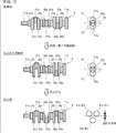
- FIG. 9 is a schematic diagram showing a manufacturing process of the forged crankshaft in the second embodiment.
- the method for manufacturing a forged crankshaft according to the second embodiment includes steps of first preforming, second preforming, finish punching, and twisting, and if necessary, before twisting. Each process of deburring and shaping after torsion molding is included.
- the first pre-molding step is a step of modeling the above-described rough material 4.
- the finish punching material in which the final shape of the forged crankshaft is formed from the rough material 4 except for the arrangement angle of the pin portion by using the forming apparatus shown in FIG. 5 is a step of molding 5.
- the finish punching step is a step of obtaining the above finish material 6 in which the finish punching material 5 is provided and the final shape of the forged crankshaft is formed except for the arrangement angle of the pin portion.
- the twist forming process is a process for obtaining the above-described twist finish material 7.
- the journal portion and the pin portion of the finishing material 6 are held and twisted about the axis of the journal portion.
- the twist angle of the forged crankshaft is adjusted to match the crankshaft, and the final shape of the forged crankshaft is shaped, including the pinned angle, by adjusting the pin angle to the pin angle of the forged crankshaft. 7 can be obtained.
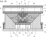
- FIG. 10 is a longitudinal sectional view showing the configuration of the forming device in the second embodiment.
- FIG. 10 illustrates a forming apparatus for forming the finishing material 5 from the rough material 4 shown in FIG.
- the vertical cross section shown in FIG. 10 actually includes all the rough pin portions on the same plane.
- the coarse material 4 is accommodated in the mold in a posture in which the eccentric direction of the coarse pin portion Pa is matched with the vertical direction.
- the rough material 4 is in a posture in which the first and third rough pin portions P1a and P3a are arranged on the top and the second rough pin portion P2a is arranged on the bottom.
- the rough material 4 in this posture is formed into a finishing material 5. Since the configuration other than this point is the same as that of the molding apparatus of the first embodiment shown in FIG.
- FIG. 11A and FIG. 11B are longitudinal sectional views for explaining a method of forming a finishing material by the forming apparatus of the second embodiment shown in FIG. Among these drawings, FIG. 11A shows a state in the initial stage of molding, and FIG. 11B shows a state when the molding is completed.
- the raw material 4 is accommodated in the lower movable journal mold 10B, the fixed journal mold 9B, the movable pin mold 12 and the auxiliary pin mold 13, and the press machine is reduced. Then, the movable journal molds 10U and 10B holding the respective coarse journal portions Ja are moved in the axial direction toward the reference pin mold 11 addressed to the second coarse pin portion P2a. The movable pin mold 12 and the auxiliary pin mold 13 addressed to the third rough pin portions P1a and P3a also move in the axial direction toward the reference pin mold 11.
- the coarse material 4 maintains the axial lengths of the coarse journal portion Ja and the coarse pin portion Pa by the movable journal types 10U and 10B, the fixed journal types 9U and 9B, the reference pin type 11 and the movable pin type 12.
- the weighted coarse arm portion Aa is pinched in the axial direction.
- the thickness of the coarse arm portion Aa with weight decreases to the thickness of the coarse arm portion Ab with weight of the finishing material 5 (see FIG. 11B).
- the reference pin mold 11 and the movable pin mold 12 are individually moved along with the driving of the respective hydraulic cylinders 16.
- the coarse pin portion Pa of the coarse material 4 is pressed in a direction perpendicular to the axial direction.
- the eccentric amount of the coarse pin portion of the finish punching material 5 is maintained even though the arrangement angle deviates from the normal position. It will be in the state which increased to the eccentric amount of Pb (refer FIG. 8, FIG. 11B).
- the shape of the forging crankshaft (final forged product) for the three-cylinder engine is almost the same as the shape of the finishing material 5 without burr. Can be molded. Then, if such a finish-free material 5 without burrs is subjected to finish punching, some burrs are generated, but the final shape of the forged crankshaft for a three-cylinder engine is excluded except for the pin arrangement angle. Can be obtained. And if this finishing material 6 is twisted, the final shape of the forged crankshaft for a three-cylinder engine can be formed, including the arrangement angle of the pin portion. Accordingly, a forged crankshaft for a three-cylinder engine can be manufactured with high yield and high dimensional accuracy regardless of its shape.
- the third embodiment is based on the configuration of the first and second embodiments.
- the third embodiment is intended to form the final shape of the crankshaft in the finish punching process without adding a twist forming process to the manufacturing process of the forged crankshaft, and the related configuration is modified. .
- FIG. 12 shows a rough material to be molded by a molding apparatus, a finished finishing material, and a finishing material after finishing punching in the manufacturing method of the third embodiment. It is a figure which shows typically each shape of.
- FIG. 12 shows a situation in which a crankshaft of a three-cylinder / four-counter weight is manufactured as in FIGS.
- the coarse material 4 of the third embodiment has a rough crankshaft shape as a whole while relying on the shape of the forged crankshaft 1 of a three-cylinder / four-piece counterweight.
- the coarse material 4 includes four coarse journal portions Ja, three coarse pin portions Pa, a coarse front portion Fra, a coarse flange portion Fla, and six coarse arm portions Aa.
- the finish punching material 5 according to the third embodiment is formed from the above-described rough material 4 by a molding device which will be described in detail later.
- the finishing material 5 includes four rough journal portions Jb, three rough pin portions Pb, a rough front portion Frb, a rough flange portion Flb, and six rough arm portions Ab.
- the finishing material 6 of the third embodiment is obtained by finishing the above-mentioned finishing material 5.
- the finishing material 6 includes four journal portions Jc, three pin portions Pc, a front portion Frc, a flange portion Flc, and six arm portions Ac.
- the shape of the finishing material 6 matches the shape of the crankshaft (final forging product) including the arrangement angle of the pin portion Pc. That is, the journal portion Jc of the finishing material 6 has the same axial length as the journal portion J of the final shape forged crankshaft.
- the pin portion Pc of the finishing material 6 has the same axial length as the pin portion P of the final shape forged crankshaft. Further, the pin portion Pc of the finishing material 6 has the same amount of eccentricity in the direction perpendicular to the axial direction and the same arrangement angle of 120 ° with respect to the pin portion P of the final shape forged crankshaft. Is arranged.
- the arm portion Ac of the finishing material 6 has the same axial thickness as the arm portion A of the final shape forged crankshaft.
- the rough journal portion Jb of the finishing material 5 has the same axial length as the journal portion Jc of the finishing material 6, that is, the journal portion J of the forged crankshaft.
- the rough pin portion Pb of the finishing material 5 has the same axial length as the pin portion Pc of the finishing material 6, that is, the pin portion P of the forged crankshaft, but the eccentricity and the arrangement angle are normal positions. It is off.
- the eccentric amounts of the first and third rough pin portions P1b and P3b at both ends of the rough pin portion Pb of the finish punching material 5 are offset in the opposite directions to each other. It is the same as ⁇ 3 / 2 of the core amount.
- the center second coarse pin portion P2b is not eccentric, and the amount of eccentricity is zero.
- the rough arm portion Ab of the finishing material 5 has the same axial thickness as the arm portion A of the final shape forged crankshaft (the arm portion Ac of the finishing material 6).
- the coarse journal portion Ja of the coarse material 4 has the same axial length as the coarse journal portion Jb of the finishing material 5, that is, the journal portion J of the forged crankshaft (the journal portion Jc of the finish material 6). .
- the coarse pin portion Pa of the coarse material 4 has the same axial length as the coarse pin portion Pb of the finish punching material 5, that is, the pin portion P of the forged crankshaft (the pin portion Pc of the finish material 6).
- the eccentric amount of the first and third coarse pin portions P1a and P3a out of the coarse pin portion Pa of the coarse material 4 is smaller than that of the finish punching material 5, and the pins of the forged crankshaft are opposite to each other.
- the eccentric amount of the portion P is smaller than ⁇ 3 / 2.
- the eccentric amount of the second rough pin portion P2a is zero, similar to that of the finish punching material 5.
- the coarse arm portions Aa of the coarse material 4 correspond to the finishing materials corresponding to each. Thickness in the axial direction is thicker than the weighted rough arm portion Ab 5, that is, the weighted arm portion A of the forged crankshaft (the arm portion Ac with the weight of the finishing material 6).
- the oval coarse arm portion Aa (third and fourth coarse arm portions A3a, A4a) of the coarse material 4 is the oval coarse arm portion Ab of the finishing material 5 corresponding to each, that is, the oval shape of the forged crankshaft.
- the thickness in the axial direction is the same as the shape arm portion A (the oval arm portion Ac of the finishing material 6).
- FIG. 13 is a schematic diagram showing a manufacturing process of the forged crankshaft in the third embodiment.
- the forged crankshaft manufacturing method of the third embodiment includes first preforming, second preforming, and finish punching, and each step of deburring and shaping as necessary. including.
- the first pre-molding step is a step of modeling the above-described rough material 4.
- the final shape of the forged crankshaft was formed from the raw material 4 except for the eccentric amount and the arrangement angle of all the pin portions by using the forming apparatus shown in FIG. This is a step of forming the finishing material 5 described above.
- Finishing process is a process for obtaining the finishing material 6 described above.
- the above-described finish punching material 5 is provided, and in a state in which the first and third rough pin portions are horizontally arranged, press forging using a pair of upper and lower dies, The rough pin portion is pressed in the vertical direction perpendicular to the axial direction.
- the finishing material 6 having a shape that matches the crankshaft, in which the final shape of the forged crankshaft is formed including the arrangement angle of the pin portion.
- FIG. 14 is a longitudinal sectional view showing the structure of the forming apparatus in the third embodiment.
- FIG. 14 illustrates a forming apparatus for forming the finishing material 5 from the rough material 4 shown in FIG.
- the vertical cross section shown in FIG. 14 actually includes all the rough pin portions on the same plane.
- the molding apparatus of the third embodiment shown in FIG. 14 is largely different in the following points.
- the coarse material 4 is accommodated in the mold in a posture in which the first and third coarse pin portions P1a and P3a eccentric in opposite directions are arranged along the vertical direction.
- the rough material 4 in this posture is formed into a finishing material 5.
- the reference pin mold 11 arranged at the position of the second rough pin portion P2a is restricted not only in the axial direction but also in the direction perpendicular to the axial direction.
- the reference pin mold 11 of the third embodiment is not connected to the hydraulic cylinder as in the first and second embodiments, and the reference pin mold 11 of the upper mold support base 23 and the lower mold support base 22 Can be attached directly to one side. On the other side, an auxiliary pin mold 13 that is paired with the reference pin mold 11 is directly attached.
- FIG. 14 shows a mode in which the reference pin mold 11 is attached to the upper mold support base 23 and the auxiliary pin mold 13 is attached to the lower mold support base 22.
- the movable pin mold 12 and the auxiliary pin mold 13 arranged at the positions of the first and third rough pin portions P1a and P3a are connected to the positions of the first rough pin portion P1a and the first The upper and lower arrangements are switched at the position of the three coarse pin portions P3a. This is because the first and third rough pin portions P1a and P3a are eccentric in the opposite directions in the vertical direction.
- the auxiliary pin mold 13 at the position of the first rough pin portion P1a and the movable pin mold 12 at the position of the third rough pin portion P3a are arranged on the upper side, and the movable pin mold at the position of the first rough pin portion P1a. 12 and the auxiliary pin mold 13 at the position of the third rough pin portion P3a are arranged on the lower side.
- FIG. 15A and 15B are longitudinal sectional views for explaining a method of forming a finishing material by the forming apparatus of the third embodiment shown in FIG. Among these drawings, FIG. 15A shows a state in the initial stage of molding, and FIG. 15B shows a state when the molding is completed.
- the raw material 4 is accommodated in the lower movable journal mold 10B, the fixed journal mold 9B, the movable pin mold 12 and the auxiliary pin mold 13, and the press machine is reduced. Then, first, the coarse material 4 is held in such a manner that each coarse journal portion Ja is sandwiched from above and below by the movable journal types 10U, 10B and the fixed journal types 9U, 9B, and at the same time, the second coarse pin portion P2a is a reference pin type. 11 and the auxiliary pin mold 13 are sandwiched and held from above and below, and the movable pin mold 12 is assigned to the first and third rough pin portions P1a and P3a.
- the movable journal molds 10U and 10B holding the respective coarse journal parts Ja move in the axial direction toward the reference pin mold 11 holding the second coarse pin part P2a
- the movable pin mold 12 and the auxiliary pin mold 13 addressed to the first and third rough pin portions P1a and P3a also move in the axial direction toward the reference pin mold 11.
- the coarse material 4 maintains the axial lengths of the coarse journal portion Ja and the coarse pin portion Pa by the movable journal types 10U and 10B, the fixed journal types 9U and 9B, the reference pin type 11 and the movable pin type 12.
- the weighted coarse arm portion Aa is pinched in the axial direction.
- the thickness of the coarse arm portion Aa with weight decreases to the thickness of the coarse arm portion Ab with weight of the finishing material 5 (see FIG. 15B).
- the movable pin molds 12 are individually divided into coarse materials 4 as the hydraulic cylinders 16 are driven.
- the first and third rough pin portions P1a and P3a are pressed in the vertical direction perpendicular to the axial direction.
- the first and third rough pin portions P1a and P3a of the coarse material 4 are displaced in the vertical direction perpendicular to the axial direction, so that the eccentricity of the eccentricity of the pin portion P of the forged crankshaft in the opposite direction is ⁇ 3 / It will be in the state increased to the same eccentricity amount as 2 (refer to Drawing 12 and Drawing 15B).
- the second coarse pin portion P2a of the coarse material 4 is maintained in a state in which the position in the direction perpendicular to the axial direction is unchanged before and after molding, and the eccentricity remains zero.
- the shape of the burrs is substantially the same as the shape of the forged crankshaft (final forged product) for a three-cylinder engine.
- No finishing material 5 can be formed. Then, such a burr-free finishing material 5 is subjected to finishing, and finishing is performed in a state where the first and third rough pin portions are horizontally arranged.
- the final shape of the forged crankshaft for a three-cylinder engine can be formed including the shape, the eccentric amount of the pin portion, and the arrangement angle. Accordingly, a forged crankshaft for a three-cylinder engine can be manufactured with high yield and high dimensional accuracy regardless of its shape.
- Fourth Embodiment is a modification of the configuration of the third embodiment.
- FIG. 16 is a diagram illustrating a rough material to be molded by a molding apparatus, a formed finish material, and a finish material after finish punching in the manufacturing method according to the fourth embodiment. It is a figure which shows typically each shape of.
- the finishing material 6 of the fourth embodiment has the same shape as the finishing material 6 of the third embodiment shown in FIG.
- the finishing material 5 of the fourth embodiment differs from the finishing material 5 of the third embodiment shown in FIG. 12 in the following points.
- the center second rough pin portion P2b in the finishing material 5 of the fourth embodiment is in a direction orthogonal to the eccentric direction of the first and third rough pin portions P1b and P3b at both ends.
- the eccentricity is the same as the pin portion Pc of the finishing material 6, that is, the pin portion P of the forged crankshaft.
- the coarse material 4 of the fourth embodiment differs from the coarse material 4 of the third embodiment shown in FIG. 12 in the following points.
- the second coarse pin portion P2a at the center of the coarse material 4 of the fourth embodiment is eccentric in a direction perpendicular to the eccentric directions of the first and third coarse pin portions P1a and P3a at both ends.
- the amount of eccentricity is the same as that of the pin portion P of the forged crankshaft (the pin portion Pc of the finishing material 6), similar to that of the finish punching material 5.
- FIG. 17 is a schematic diagram showing a manufacturing process of the forged crankshaft in the fourth embodiment.
- the forged crankshaft manufacturing method of the fourth embodiment includes the steps of the first preforming, the second preforming, and the finishing punching, as in the third embodiment shown in FIG. , Deburring and shaping steps are included as necessary.
- the first pre-molding step is a step of modeling the above-described rough material 4.
- the second pre-molding step is a step of molding the finishing material 5 described above.
- the same molding apparatus as that of the third embodiment shown in FIGS. 14, 15A and 15B is used.
- the portion of the second rough pin portion is actually located in front of or behind the paper.
- the lower journal mold 10B, the fixed journal mold 9B, the movable pin mold 12, and the auxiliary pin as in the third embodiment shown in FIGS. 14, 15A and 15B.
- the raw material 4 is accommodated in the mold 13 and the press machine is reduced. Accordingly, the movable journal molds 10U and 10B holding the respective coarse journal portions Ja, and the movable pin mold 12 and the auxiliary pin mold 13 addressed to the first and third coarse pin sections P1a and P3a are replaced with the second coarse pin. It moves in the axial direction toward the reference pin mold 11 holding the part P2a.
- the coarse arm portion Aa with weight is pinched in the axial direction while the axial lengths of the coarse journal portion Ja and the coarse pin portion Pa are maintained. Then, the thickness of the coarse arm portion Aa with weight is reduced to the thickness of the coarse arm portion Ab with weight of the finishing material 5.
- the movable pin mold 12 presses the first and third rough pin portions P1a and P3a in the vertical direction perpendicular to the axial direction.
- the first and third rough pin portions P1a and P3a of the coarse material 4 are increased to the same eccentric amount as ⁇ 3 / 2 of the eccentric amount of the pin portion P of the forged crankshaft in opposite directions.
- the second coarse pin portion P2a of the coarse material 4 is maintained before and after molding without changing the position in the direction perpendicular to the axial direction, and the eccentric amount is the eccentric amount of the pin portion of the forged crankshaft. Will remain the same.
- the rough material 4 without burrs substantially matches the shape of the forged crankshaft (final forged product) for a three-cylinder engine except for the eccentric amount and the arrangement angle of the first and third pin portions P1 and P3.
- the finish punching material 5 having a shape and no burrs can be formed.
- Finishing process is a process for obtaining the finishing material 6 described above.
- the finish punching material 5 is provided, and finish punching is performed in a state in which the first and third rough pin portions are arranged horizontally.
- the first and third rough pin portions P1b and P3b of the finishing material 5 are pressed in the vertical direction perpendicular to the axial direction to be displaced to the normal position. If this is done, some burrs will occur, but the final shape of the forged crankshaft for the three-cylinder engine including the contour shape of the arm part, the eccentric amount of the pin part and the arrangement angle will match the crankshaft.
- a finishing material 6 having a shape can be obtained.
- the present invention is not limited to the above-described embodiment, and various modifications can be made without departing from the spirit of the present invention.
- a wedge mechanism using a press machine is employed in the above embodiment, but the present invention is not limited to this, and a link mechanism may be employed.
- a hydraulic cylinder, a servo motor, or the like may be used.
- the mechanism for moving the pin mold in the direction perpendicular to the axial direction is not limited to the hydraulic cylinder but may be a servo motor.
- an inclined surface is provided on the end surface of the movable journal mold, and a wedge is provided corresponding to the inclined surface.
- a block having an inclined surface may be fixed to a side portion of the movable journal type that is out of the first and second engraved portions, and a wedge corresponding to the inclined surface of the block may be provided. I do not care.
- the upper mold support base is fixed to the upper hard plate
- the lower mold support base is elastically supported by the lower hard plate
- a wedge is placed on the lower hard plate.
- the upper and lower movable journal types are moved by the wedge, but a configuration in which the upper and lower sides are inverted may be used.
- the upper and lower mold support bases can be elastically supported by the respective hard plates, wedges can be installed on the hard plates, and the upper and lower movable journal molds can be moved by the respective wedges.
- the auxiliary pin type is allowed to move only in the axial direction.
- the auxiliary pin type may be allowed to move in the direction toward the paired pin type.
- the pin type and the auxiliary pin type move in a direction perpendicular to the axial direction in conjunction with each other while holding each coarse pin portion Pa sandwiched from above and below.
- the pin type is moved in the vertical direction perpendicular to the axial direction to press the rough pin portion Pa in the vertical direction.
- the pin is configured to press the rough pin portion Pa in the horizontal direction.
- the arrangement of the mold and the journal mold can be modified.
- the present invention is useful when manufacturing a forged crankshaft for a three-cylinder engine.
Priority Applications (5)
| Application Number | Priority Date | Filing Date | Title |
|---|---|---|---|
| MX2016011094A MX2016011094A (es) | 2014-02-27 | 2015-02-18 | Aparato para formar una pieza en blanco para acabado por forja para un cigüeñal forjado para un motor de tres cilindros y metodo de fabricacion de un cigüeñal forjado para un motor de tres cilindros utilizando la misma. |
| US15/118,174 US10029297B2 (en) | 2014-02-27 | 2015-02-18 | Apparatus for forming a blank for finish forging for a forged crankshaft for a three-cylinder engine and method for manufacturing a forged crankshaft for a three-cylinder engine using the same |
| JP2016505046A JP6179660B2 (ja) | 2014-02-27 | 2015-02-18 | 3気筒エンジン用鍛造クランク軸の仕上打ち用素材の成形装置、及びこれを用いた3気筒エンジン用鍛造クランク軸の製造方法 |
| CN201580010490.6A CN106061646B (zh) | 2014-02-27 | 2015-02-18 | 三汽缸发动机用锻造曲轴的精锻用坯料的成形装置和使用该成形装置的三汽缸发动机用锻造曲轴的制造方法 |
| EP15755525.1A EP3112046B1 (en) | 2014-02-27 | 2015-02-18 | Apparatus for forming a blank for finish-forging for a forged crankshaft for a three-cylinder engine and method for manufacturing a forged crankshaft for a three-cylinder engine using the same |
Applications Claiming Priority (2)
| Application Number | Priority Date | Filing Date | Title |
|---|---|---|---|
| JP2014-036730 | 2014-02-27 | ||
| JP2014036730 | 2014-02-27 |
Publications (1)
| Publication Number | Publication Date |
|---|---|
| WO2015129208A1 true WO2015129208A1 (ja) | 2015-09-03 |
Family
ID=54008545
Family Applications (1)
| Application Number | Title | Priority Date | Filing Date |
|---|---|---|---|
| PCT/JP2015/000772 WO2015129208A1 (ja) | 2014-02-27 | 2015-02-18 | 3気筒エンジン用鍛造クランク軸の仕上打ち用素材の成形装置、及びこれを用いた3気筒エンジン用鍛造クランク軸の製造方法 |
Country Status (6)
| Country | Link |
|---|---|
| US (1) | US10029297B2 (zh) |
| EP (1) | EP3112046B1 (zh) |
| JP (1) | JP6179660B2 (zh) |
| CN (1) | CN106061646B (zh) |
| MX (1) | MX2016011094A (zh) |
| WO (1) | WO2015129208A1 (zh) |
Cited By (3)
| Publication number | Priority date | Publication date | Assignee | Title |
|---|---|---|---|---|
| WO2019181366A1 (ja) * | 2018-03-20 | 2019-09-26 | 日本製鉄株式会社 | 鍛造クランク軸の製造方法 |
| CN110792684A (zh) * | 2019-11-08 | 2020-02-14 | 陕西航天动力高科技股份有限公司 | 一种隔膜泵用三缸三支撑曲轴及加工工艺 |
| US11045865B2 (en) * | 2017-08-21 | 2021-06-29 | Nippon Steel Corporation | Method for producing forged crankshaft |
Families Citing this family (4)
| Publication number | Priority date | Publication date | Assignee | Title |
|---|---|---|---|---|
| EP3549691A1 (en) * | 2016-11-29 | 2019-10-09 | Nippon Steel Corporation | Production method for forged crankshaft |
| MX2019015091A (es) * | 2017-06-15 | 2020-02-17 | Nippon Steel Corp | Metodo para producir cigue?al forjado. |
| BR112020001910A2 (pt) * | 2017-08-21 | 2020-07-28 | Nippon Steel Corporation | método de produção de virabrequim forjado |
| JP7472802B2 (ja) * | 2021-01-20 | 2024-04-23 | トヨタ自動車株式会社 | クランクシャフト |
Citations (3)
| Publication number | Priority date | Publication date | Assignee | Title |
|---|---|---|---|---|
| WO2012035663A1 (ja) * | 2010-09-17 | 2012-03-22 | トヨタ自動車株式会社 | クランクシャフトの製造方法およびクランクシャフトの製造装置 |
| JP2012086265A (ja) * | 2010-10-22 | 2012-05-10 | Metalart Corp | クランクシャフトの製造方法及びその製法によって製造されたクランクシャフト |
| JP2012161819A (ja) * | 2011-02-08 | 2012-08-30 | Toyota Motor Corp | クランクシャフトの製造装置、クランクシャフトの製造方法、およびクランクシャフト |
Family Cites Families (8)
| Publication number | Priority date | Publication date | Assignee | Title |
|---|---|---|---|---|
| RU2247623C2 (ru) * | 2002-12-24 | 2005-03-10 | Воронежская ЗАО по выпуску тяжелых механических прессов | Способ изготовления коленчатого вала |
| JP4944598B2 (ja) | 2006-12-26 | 2012-06-06 | 株式会社神戸製鋼所 | 一体型クランク軸の鍛造装置 |
| CN201144953Y (zh) * | 2007-12-27 | 2008-11-05 | 伟业汽车动力机械有限公司 | 发动机曲轴 |
| EP2274120B9 (en) * | 2008-02-29 | 2012-11-07 | Perkins Engines Company Limited | Metal forged crankshaft, apparatus for metal forging a crankshaft and method of metal forging a crankshaft |
| JP2011110592A (ja) * | 2009-11-27 | 2011-06-09 | Toyota Motor Corp | クランクシャフトの製造装置、及び、クランクシャフトの製造方法 |
| JP2011161496A (ja) | 2010-02-12 | 2011-08-25 | Toyota Motor Corp | クランクシャフトの製造装置、及び、クランクシャフトの製造方法 |
| BR112015013479A2 (pt) * | 2012-12-12 | 2017-07-11 | Nippon Steel & Sumitomo Metal Corp | eixo de manivela forjado e método de produção do mesmo |
| JP5751389B2 (ja) * | 2012-12-12 | 2015-07-22 | 新日鐵住金株式会社 | 3気筒エンジン用鍛造クランク軸の仕上打ち用素材の成形装置、およびこれを用いた3気筒エンジン用鍛造クランク軸の製造方法 |
-
2015
- 2015-02-18 WO PCT/JP2015/000772 patent/WO2015129208A1/ja active Application Filing
- 2015-02-18 JP JP2016505046A patent/JP6179660B2/ja active Active
- 2015-02-18 EP EP15755525.1A patent/EP3112046B1/en not_active Not-in-force
- 2015-02-18 MX MX2016011094A patent/MX2016011094A/es active IP Right Grant
- 2015-02-18 CN CN201580010490.6A patent/CN106061646B/zh active Active
- 2015-02-18 US US15/118,174 patent/US10029297B2/en active Active
Patent Citations (3)
| Publication number | Priority date | Publication date | Assignee | Title |
|---|---|---|---|---|
| WO2012035663A1 (ja) * | 2010-09-17 | 2012-03-22 | トヨタ自動車株式会社 | クランクシャフトの製造方法およびクランクシャフトの製造装置 |
| JP2012086265A (ja) * | 2010-10-22 | 2012-05-10 | Metalart Corp | クランクシャフトの製造方法及びその製法によって製造されたクランクシャフト |
| JP2012161819A (ja) * | 2011-02-08 | 2012-08-30 | Toyota Motor Corp | クランクシャフトの製造装置、クランクシャフトの製造方法、およびクランクシャフト |
Cited By (4)
| Publication number | Priority date | Publication date | Assignee | Title |
|---|---|---|---|---|
| US11045865B2 (en) * | 2017-08-21 | 2021-06-29 | Nippon Steel Corporation | Method for producing forged crankshaft |
| WO2019181366A1 (ja) * | 2018-03-20 | 2019-09-26 | 日本製鉄株式会社 | 鍛造クランク軸の製造方法 |
| CN110792684A (zh) * | 2019-11-08 | 2020-02-14 | 陕西航天动力高科技股份有限公司 | 一种隔膜泵用三缸三支撑曲轴及加工工艺 |
| CN110792684B (zh) * | 2019-11-08 | 2023-12-08 | 陕西航天动力高科技股份有限公司 | 一种隔膜泵用三缸三支撑曲轴及加工工艺 |
Also Published As
| Publication number | Publication date |
|---|---|
| US20170173664A1 (en) | 2017-06-22 |
| EP3112046B1 (en) | 2018-11-21 |
| MX2016011094A (es) | 2017-02-20 |
| JP6179660B2 (ja) | 2017-08-16 |
| JPWO2015129208A1 (ja) | 2017-03-30 |
| EP3112046A4 (en) | 2017-12-13 |
| CN106061646B (zh) | 2017-12-22 |
| EP3112046A1 (en) | 2017-01-04 |
| CN106061646A (zh) | 2016-10-26 |
| US10029297B2 (en) | 2018-07-24 |
Similar Documents
| Publication | Publication Date | Title |
|---|---|---|
| JP5924440B2 (ja) | 3気筒エンジン用鍛造クランク軸の仕上打ち用素材の成形装置 | |
| JP6179660B2 (ja) | 3気筒エンジン用鍛造クランク軸の仕上打ち用素材の成形装置、及びこれを用いた3気筒エンジン用鍛造クランク軸の製造方法 | |
| JP5708893B2 (ja) | 鍛造クランク軸の仕上打ち用素材の成形装置 | |
| JP6020766B2 (ja) | 直列6気筒エンジン用鍛造クランク軸の仕上打ち用素材の成形装置、及びこれを用いた直列6気筒エンジン用鍛造クランク軸の製造方法 | |
| JP6172376B2 (ja) | V型6気筒エンジン用鍛造クランク軸の仕上打ち用素材の成形装置、及びこれを用いたv型6気筒エンジン用鍛造クランク軸の製造方法 | |
| JP6172377B2 (ja) | V型6気筒エンジン用鍛造クランク軸の仕上打ち用素材の成形装置、及びこれを用いたv型6気筒エンジン用鍛造クランク軸の製造方法 | |
| JP6179659B2 (ja) | 4気筒エンジン用鍛造クランク軸の仕上打ち用素材の成形装置、及びこれを用いた4気筒エンジン用鍛造クランク軸の製造方法 | |
| JP6160765B2 (ja) | 直列6気筒エンジン用鍛造クランク軸の仕上打ち用素材の成形装置、及びこれを用いた直列6気筒エンジン用鍛造クランク軸の製造方法 | |
| CN109982784B (zh) | 锻造曲轴的制造方法 | |
| JPWO2018230500A1 (ja) | 鍛造クランク軸の製造方法 |
Legal Events
| Date | Code | Title | Description |
|---|---|---|---|
| 121 | Ep: the epo has been informed by wipo that ep was designated in this application |
Ref document number: 15755525 Country of ref document: EP Kind code of ref document: A1 |
|
| ENP | Entry into the national phase |
Ref document number: 2016505046 Country of ref document: JP Kind code of ref document: A |
|
| WWE | Wipo information: entry into national phase |
Ref document number: 15118174 Country of ref document: US |
|
| WWE | Wipo information: entry into national phase |
Ref document number: MX/A/2016/011094 Country of ref document: MX |
|
| NENP | Non-entry into the national phase |
Ref country code: DE |
|
| REG | Reference to national code |
Ref country code: BR Ref legal event code: B01A Ref document number: 112016018963 Country of ref document: BR |
|
| REEP | Request for entry into the european phase |
Ref document number: 2015755525 Country of ref document: EP |
|
| WWE | Wipo information: entry into national phase |
Ref document number: 2015755525 Country of ref document: EP |
|
| ENP | Entry into the national phase |
Ref document number: 112016018963 Country of ref document: BR Kind code of ref document: A2 Effective date: 20160817 |