WO2015129106A1 - カメラモジュールおよび撮像装置 - Google Patents
カメラモジュールおよび撮像装置 Download PDFInfo
- Publication number
- WO2015129106A1 WO2015129106A1 PCT/JP2014/080363 JP2014080363W WO2015129106A1 WO 2015129106 A1 WO2015129106 A1 WO 2015129106A1 JP 2014080363 W JP2014080363 W JP 2014080363W WO 2015129106 A1 WO2015129106 A1 WO 2015129106A1
- Authority
- WO
- WIPO (PCT)
- Prior art keywords
- imaging lens
- image
- imaging
- lens
- captured image
- Prior art date
- Legal status (The legal status is an assumption and is not a legal conclusion. Google has not performed a legal analysis and makes no representation as to the accuracy of the status listed.)
- Ceased
Links
Images





Classifications
-
- H—ELECTRICITY
- H04—ELECTRIC COMMUNICATION TECHNIQUE
- H04N—PICTORIAL COMMUNICATION, e.g. TELEVISION
- H04N23/00—Cameras or camera modules comprising electronic image sensors; Control thereof
- H04N23/60—Control of cameras or camera modules
- H04N23/68—Control of cameras or camera modules for stable pick-up of the scene, e.g. compensating for camera body vibrations
- H04N23/682—Vibration or motion blur correction
- H04N23/685—Vibration or motion blur correction performed by mechanical compensation
- H04N23/687—Vibration or motion blur correction performed by mechanical compensation by shifting the lens or sensor position
-
- G—PHYSICS
- G02—OPTICS
- G02B—OPTICAL ELEMENTS, SYSTEMS OR APPARATUS
- G02B27/00—Optical systems or apparatus not provided for by any of the groups G02B1/00 - G02B26/00, G02B30/00
- G02B27/64—Imaging systems using optical elements for stabilisation of the lateral and angular position of the image
-
- G—PHYSICS
- G02—OPTICS
- G02B—OPTICAL ELEMENTS, SYSTEMS OR APPARATUS
- G02B13/00—Optical objectives specially designed for the purposes specified below
- G02B13/0005—Optical objectives specially designed for the purposes specified below having F-Theta characteristic
-
- G—PHYSICS
- G02—OPTICS
- G02B—OPTICAL ELEMENTS, SYSTEMS OR APPARATUS
- G02B27/00—Optical systems or apparatus not provided for by any of the groups G02B1/00 - G02B26/00, G02B30/00
- G02B27/64—Imaging systems using optical elements for stabilisation of the lateral and angular position of the image
- G02B27/646—Imaging systems using optical elements for stabilisation of the lateral and angular position of the image compensating for small deviations, e.g. due to vibration or shake
-
- G—PHYSICS
- G03—PHOTOGRAPHY; CINEMATOGRAPHY; ANALOGOUS TECHNIQUES USING WAVES OTHER THAN OPTICAL WAVES; ELECTROGRAPHY; HOLOGRAPHY
- G03B—APPARATUS OR ARRANGEMENTS FOR TAKING PHOTOGRAPHS OR FOR PROJECTING OR VIEWING THEM; APPARATUS OR ARRANGEMENTS EMPLOYING ANALOGOUS TECHNIQUES USING WAVES OTHER THAN OPTICAL WAVES; ACCESSORIES THEREFOR
- G03B5/00—Adjustment of optical system relative to image or object surface other than for focusing
- G03B5/02—Lateral adjustment of lens
-
- H—ELECTRICITY
- H04—ELECTRIC COMMUNICATION TECHNIQUE
- H04N—PICTORIAL COMMUNICATION, e.g. TELEVISION
- H04N23/00—Cameras or camera modules comprising electronic image sensors; Control thereof
- H04N23/50—Constructional details
- H04N23/54—Mounting of pick-up tubes, electronic image sensors, deviation or focusing coils
-
- H—ELECTRICITY
- H04—ELECTRIC COMMUNICATION TECHNIQUE
- H04N—PICTORIAL COMMUNICATION, e.g. TELEVISION
- H04N23/00—Cameras or camera modules comprising electronic image sensors; Control thereof
- H04N23/50—Constructional details
- H04N23/55—Optical parts specially adapted for electronic image sensors; Mounting thereof
-
- H—ELECTRICITY
- H04—ELECTRIC COMMUNICATION TECHNIQUE
- H04N—PICTORIAL COMMUNICATION, e.g. TELEVISION
- H04N23/00—Cameras or camera modules comprising electronic image sensors; Control thereof
- H04N23/57—Mechanical or electrical details of cameras or camera modules specially adapted for being embedded in other devices
-
- H—ELECTRICITY
- H04—ELECTRIC COMMUNICATION TECHNIQUE
- H04N—PICTORIAL COMMUNICATION, e.g. TELEVISION
- H04N23/00—Cameras or camera modules comprising electronic image sensors; Control thereof
- H04N23/60—Control of cameras or camera modules
-
- G—PHYSICS
- G03—PHOTOGRAPHY; CINEMATOGRAPHY; ANALOGOUS TECHNIQUES USING WAVES OTHER THAN OPTICAL WAVES; ELECTROGRAPHY; HOLOGRAPHY
- G03B—APPARATUS OR ARRANGEMENTS FOR TAKING PHOTOGRAPHS OR FOR PROJECTING OR VIEWING THEM; APPARATUS OR ARRANGEMENTS EMPLOYING ANALOGOUS TECHNIQUES USING WAVES OTHER THAN OPTICAL WAVES; ACCESSORIES THEREFOR
- G03B2205/00—Adjustment of optical system relative to image or object surface other than for focusing
- G03B2205/0007—Movement of one or more optical elements for control of motion blur
- G03B2205/0015—Movement of one or more optical elements for control of motion blur by displacing one or more optical elements normal to the optical axis
Definitions
- the present invention relates to a camera module and an imaging apparatus including an OIS (Optical Image Stabilizer) that shifts at least one of an imaging lens and an imaging element.
- OIS Optical Image Stabilizer
- an image pickup apparatus such as a digital video camera and a digital still camera
- an apparatus equipped with an OIS that corrects a shake of a picked-up image caused by camera shake has been put into practical use.
- the OIS has a gyro sensor that detects the tilt of the imaging device due to camera shake based on angular velocity or the like.
- the OIS shifts the imaging lens or the imaging element in the normal direction with respect to the optical axis of the imaging lens based on the output signal of the gyro sensor. Thereby, the OIS corrects the blur of the captured image caused by the relative deviation between the light receiving surface of the image sensor and the optical axis of the imaging lens.
- the imaging apparatus can correct blurring of a captured image caused by camera shake and suppress blurring of the captured image.
- a lens shift type OIS that shifts the imaging lens is widely used because it can be configured by a compact mechanism that shifts the imaging lens.
- the lens shift type OIS there is a problem of sufficiently correcting blurring occurring in the peripheral portion of the captured image.
- the peripheral portion of the captured image is the edge of the captured image and its vicinity.
- Patent Documents 1 and 2 are examples of techniques for solving the above problems.
- Patent Document 1 discloses a technique for performing image processing for correcting distortion on a captured image.
- Patent Document 2 discloses a technique for suppressing a distortion component caused by the tilt of the imaging device during camera shake by optimizing the distortion of the imaging lens.
- JP 2006-129175 A Japanese Patent Publication “JP 2012-68540 A (published April 5, 2012)”
- Patent Document 2 still does not sufficiently correct the blur of the captured image. The reason will be described.
- the size of the image formed by the imaging lens is proportional to the tangent of the angle at which the principal ray from the subject is incident on the imaging lens.
- the peripheral light amount ratio of the captured image (ratio of the light amount around the image to the light amount at the center of the image) Can be increased, and blurring of the peripheral portion of the captured image can be improved.
- the intermediate image height region of the imaging lens distortion is positive, and as a result, blurring in the intermediate portion of the captured image becomes large.
- the intermediate portion of the captured image is a zone between the central portion of the captured image (the center of the captured image and its vicinity) and the peripheral portion of the captured image.
- the present invention has been made in view of the above-described problems, and has an object of being a small size and low manufacturing cost, and a camera module and an imaging apparatus that can more appropriately correct blurring of a captured image. Is to provide.
- a camera module includes an imaging lens, an imaging element that receives light that has passed through the imaging lens, and a principal ray from a subject that is incident on the imaging lens.
- An image stabilization mechanism that shifts at least one of the imaging lens and the imaging element in a direction normal to the optical axis of the imaging lens according to an angle of The size is proportional to the angle.
- an imaging device includes a camera module according to one embodiment of the present invention, and an image is output with respect to an output signal of the imaging element of the camera module.
- An image processing unit that performs processing is provided.
- the present invention it is small in size and low in manufacturing cost, and it is possible to correct blurring of a captured image even better.
- FIG. 1A is a graph showing the relationship between the incident angle and the image size of an imaging lens according to the prior art
- FIG. 1B is an imaging lens according to Embodiment 1 of the present invention
- FIG. 1C is a graph showing the relationship between the incident angle and the image size
- FIG. 1C shows the relationship between the imaging lens according to the prior art and the imaging lens (f ⁇ lens) according to Embodiment 1 of the present invention
- FIG. 6 is a graph comparing the relationship between the incident angle and the image size.
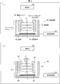
- 2A is a cross-sectional view showing the configuration of the imaging apparatus according to Embodiment 1 of the present invention
- FIG. 2B is a diagram of the OIS unit in the imaging apparatus shown in FIG. It is sectional drawing which demonstrates a function simply.
- FIG. 3 shows before correction
- FIG. 3 shows after correction
- 4A is a diagram illustrating an image formed by the imaging lens according to the related art
- FIG. 4B is a diagram illustrating an image formed by the imaging lens according to Embodiment 1 of the present invention. It is a figure to do. It is a figure which shows an example of the imaging result of a lattice chart by the imaging device which concerns on Embodiment 1 of this invention.
- 6A is a diagram illustrating a configuration example of each lens constituting the imaging lens according to the related art
- FIG. 6B constitutes the imaging lens according to Embodiment 1 of the present invention.
- FIG. 6 It is a figure which shows the structural example of each lens. It is a figure explaining the image processing by an image processing part.
- the concept of the size of each captured image shown in FIG. 7 is added to the graph shown in FIG. 6 is a graph comparing the characteristics of the size of a captured image with respect to an incident angle for an imaging apparatus including an imaging lens according to a conventional technique and an imaging apparatus including an imaging lens according to Embodiment 1 of the present invention.
- Imaging after correction of blurring when a camera shake of 1 deg with respect to an incident angle occurs with respect to an imaging apparatus including an imaging lens according to the related art and an imaging apparatus including the imaging lens according to Embodiment 1 of the present invention 6 is a graph comparing image blur characteristics.
- FIG. 6 is a graph comparing distortion characteristics with respect to an incident angle for an imaging apparatus including an imaging lens according to a conventional technique and an imaging apparatus including an imaging lens according to Embodiment 1 of the present invention.
- the characteristic regarding the captured image obtained by performing the image processing shown in the following mathematical formula (1) is added to the graph shown in FIG.
- It is the figure which compared the imaging result of the grid chart about the imaging device provided with the imaging lens concerning a prior art, and the imaging device provided with the imaging lens concerning Embodiment 1 of the present invention.
- It is the figure which compared the imaging result of the grid chart before and behind image processing about the imaging device provided with the imaging lens which concerns on Embodiment 1 of this invention.
- It is sectional drawing which illustrates easily the structure of the imaging device which concerns on Embodiment 2 of this invention, and the function of the OIS part in this imaging device.
- a lens shift type OIS that shifts an imaging lens with respect to an imaging element is often used.
- the lens shift type OIS cancels the shift of the image of the subject caused by camera shake and suppresses the blur of the image.
- the camera module and the imaging apparatus of the present invention are configured such that the size of the image formed by the imaging lens is proportional to the angle at which the principal ray from the subject is incident on the imaging lens.
- a so-called f ⁇ lens can be used as the imaging lens.
- the f ⁇ lens is such that the size of the image formed by the f ⁇ lens is proportional to the incident angle ⁇ of light on the f ⁇ lens, and the distortion characteristics dist. Is defined as follows:
- dist. 100 ⁇ ( ⁇ tan ⁇ ) / tan ⁇ (%) Further, if the distortion of the imaging lens is negative, the size of the captured image is reduced. As a result, a margin for the effective image circle diameter with respect to the captured image can be ensured, so that it is possible to perform appropriate correction for larger camera shake.
- FIG. 2A is a cross-sectional view illustrating the configuration of the imaging apparatus according to Embodiment 1, and FIG. 2B illustrates the function of the OIS unit in the imaging apparatus illustrated in FIG. FIG.
- 2A and 2B includes a camera module 101 and an image processing unit 102.
- the camera module 101 includes an imaging lens 103, an imaging element 104, a substrate 105, a lens holder, an OIS (optical camera shake correction mechanism) 106, and a housing unit 107.
- OIS optical camera shake correction mechanism
- the imaging lens 103 forms an image of the subject 200 and has at least one lens.
- FIG. 2A for convenience of illustration and description, three lenses are illustrated, but the number of lenses is not limited to three. In the following description, the same member number is assigned to the imaging lens having the same function regardless of the number of lenses constituting the imaging lens. A specific configuration of the imaging lens 103 will be described later.
- the imaging element 104 receives light that has passed through the imaging lens 103 and outputs an electrical signal obtained by photoelectrically converting the received light.
- the imaging element 104 is configured by, for example, a CCD (Charge-Coupled Device) or a CMOS (Complementary-Metal-Oxide-Semiconductor).
- the substrate 105 is one on which the image sensor 104 and the casing 107 are mounted.
- the lens holder and OIS 106 have a lens holder part and an OIS part.
- the lens holder unit is for housing the imaging lens 103.
- the OIS unit shifts the imaging lens 103 in the normal direction Ln by moving the lens holder in the normal direction Ln with respect to the optical axis La of the imaging lens 103 (see FIG. 2B). .
- the housing unit 107 is mounted on the substrate 105 and covers the image sensor 104, the lens holder, and the OIS 106.
- the portion of the housing unit 107 that forms the side surface of the imaging device 100 may function as an OIS unit (as in the rectangular cylindrical portion 23a of Patent Document 2).
- the image processing unit 102 generates an image captured by the image capturing apparatus 100 by performing image processing on an output signal (electric signal) of the image sensor 104 that indicates an image captured by the camera module 101. Image processing by the image processing unit 102 will be described later.
- the imaging lens 103 is configured such that the size of the image formed by the imaging lens 103 is proportional to the angle at which the principal ray from the subject 200 enters the imaging lens 103.
- the size of the image formed by the imaging lens means not only the size of the image of the subject, but also the size of the entire image obtained by imaging the light incident on the imaging lens. Means.
- a specific example of the imaging lens 103 is a so-called f ⁇ lens.
- the size of the image formed by the f ⁇ lens is proportional to the incident angle of light to the f ⁇ lens.
- the imaging lens 103 which is an f ⁇ lens has a negative distortion.
- the imaging lens 103 has a negative distortion
- the peripheral light amount ratio of the captured image can be increased, which is suitable for reducing noise caused by shading correction.
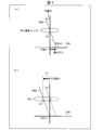
- FIG. 3A and 3B are diagrams for explaining the principle of the function of the OIS unit.
- FIG. 3A shows a state before correction
- FIG. 3B shows a state after correction. Yes.
- the principal ray 200c passes through the imaging lens 103 and is guided to the light receiving surface 104r of the imaging element 104.
- the principal ray 200c is along the optical axis La, the principal ray 200c is guided to the center 104rc of the light receiving surface 104r, and there is no need to perform correction by the OIS unit.
- the principal ray 200c is inclined with respect to the optical axis La.
- the positions of the imaging lens 103 and the light receiving surface 104r are fixed, the principal ray 200c is guided to a position 104rd deviated from the center 104rc as shown in FIG.
- the chief ray 200c being guided to the position 104rd is a main factor of blurring of the captured image.
- the OIS unit guides the principal ray 200c tilted with respect to the optical axis La due to camera shake to the center 104rc.
- the imaging lens 103 is shifted in the normal direction Ln. Thereby, in the imaging device 100, the blur of the captured image resulting from camera shake can be corrected.
- [Contrast of images formed by imaging lens] 4A is a diagram for explaining an image formed by the imaging lens according to the related art
- FIG. 4B is a diagram for explaining an image formed by the imaging lens according to the first embodiment. is there.
- the size of the image formed by the imaging lens 108 is proportional to the tangent of the angle at which the principal ray from the subject 200 is incident on the imaging lens 108.
- the principal ray 200c is guided to the center 104rc of the light receiving surface 104r.
- the amount of displacement from the center 104 rc to the position 104 re can be expressed as “f ′ ⁇ tan ⁇ ”.
- f ′ is the distance from the center of the imaging lens to the light receiving surface of the imaging element. That is, when the angle at which the chief ray 200c is incident on the imaging lens 108 is inclined by ⁇ due to camera shake, the position at which the chief ray 200c is guided shifts by “f ′ ⁇ tan ⁇ ”.
- the principal ray 200c is along the optical axis La ′ of the imaging lens 108, the principal ray 200e constituting the edge of the image of the subject 200 is guided to the position 104rf of the light receiving surface 104r.
- the principal ray 200e when a camera shake occurs in which the angle at which the principal ray 200c is incident on the imaging lens 108 is inclined by ⁇ , the principal ray 200e also exhibits the same inclination, and the principal ray 200e is guided to the position 104rg on the light receiving surface 104r.
- the amount of displacement from the position 104rf to the position 104rg can be expressed as “f ′ ⁇ ⁇ tan ( ⁇ + ⁇ ) ⁇ tan ⁇ ”.
- ⁇ is an angle formed by the principal ray 200c and the principal ray 200e. That is, when the angle at which the chief ray 200c is incident on the imaging lens 108 is inclined by ⁇ due to camera shake, the position where the chief ray 200e is guided is shifted by “f ′ ⁇ ⁇ tan ( ⁇ + ⁇ ) ⁇ tan ⁇ ”.
- the shift amount differs between the center and the edge of the image of the subject 200.
- the size of the image of the subject 200 changes depending on the value of the angle ⁇ . More specifically, as the angle ⁇ increases, the image of the subject 200 increases.
- the size of the image formed by the imaging lens 103 is proportional to the angle at which the principal ray from the subject 200 is incident on the imaging lens 103.
- the amount of displacement from the center 104 rc to the position 104 rh can be expressed as “A ⁇ f ′ ⁇ ⁇ ”.
- A is a predetermined proportional coefficient.
- the amount of displacement is proportional to f ′ ⁇ ⁇ . That is, when the angle at which the principal ray 200c is incident on the imaging lens 103 is inclined by ⁇ due to camera shake, the position at which the principal ray 200c is guided shifts by “A ⁇ f ′ ⁇ ⁇ ”.
- the principal ray 200c is along the optical axis La of the imaging lens 103, the principal ray 200e is guided to the position 104ri on the light receiving surface 104r.
- the principal ray 200e when a camera shake occurs in which the angle at which the principal ray 200c is incident on the imaging lens 103 is inclined by ⁇ , the principal ray 200e also exhibits the same inclination, and the principal ray 200e is guided to the position 104rj of the light receiving surface 104r.
- the displacement amount from the position 104ri to the position 104rj can be expressed as “A ⁇ f ′ ⁇ ( ⁇ + ⁇ ) ⁇ A ⁇ f ′ ⁇ ⁇ ”.
- a ⁇ f ′ ⁇ ⁇ is obtained, which is equal to the displacement amount from the center 104 rc to the position 104 rh. That is, when the angle at which the principal ray 200c is incident on the imaging lens 103 is inclined by ⁇ due to camera shake, the position at which the principal ray 200e is guided is shifted by “A ⁇ f ′ ⁇ ⁇ ”.
- the shift amount is the same between the center and the edge of the image of the subject 200.
- the size of the image of the subject 200 is constant regardless of the value of the angle ⁇ .
- the size of the image of the subject 200 changes due to camera shake, but this change cannot be dealt with just by shifting the imaging lens 108. Correction is insufficient.
- the size of the image of the subject 200 is constant, so that the blur of the captured image can be sufficiently corrected by simply shifting the imaging lens 103. It can be carried out.
- FIG. 5 is a diagram illustrating an example of a grid chart imaging result by the imaging apparatus according to the first embodiment.
- the lattice chart has an aspect ratio of 0.75.
- the imaging result of the lattice chart is a barrel shape as shown in FIG.
- FIG. 1A is a graph showing the relationship between the incident angle and the image size of an imaging lens according to the prior art.
- FIG. 1B is a graph showing the relationship between the incident angle and the image size of the imaging lens according to Embodiment 1.
- FIG. 1C is a graph comparing the relationship between the incident angle and the image size between the imaging lens according to the prior art and the imaging lens (f ⁇ lens) according to the first embodiment.
- the incident angle of light to the imaging lens when it is along the optical axis of the corresponding imaging lens is set as the origin.
- the size y of the image formed by the imaging lens 108 is proportional to the tangent (tan ⁇ ) of the incident angle ⁇ of light to the imaging lens 108.
- f is the focal length of the imaging lens.
- the size y of the image formed by the imaging lens 103 is proportional to the incident angle ⁇ of light on the imaging lens 103.
- the difference in the image size y becomes more significant as the incident angle ⁇ increases. I understand that.
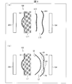
- FIG. 6A is a diagram illustrating a configuration example of each lens constituting the imaging lens according to the related art
- FIG. 6B is a diagram illustrating each lens constituting the imaging lens according to the first embodiment. It is a figure which shows the example of a structure.
- FIG. 6A For convenience of illustration, in FIG. 6A, among the lenses constituting the imaging lens 108, the surface S11 of the lens L11 positioned closest to the subject 200 and facing the subject 200, and of these lenses Only the lens L12 located closest to the image sensor 104 is shown. That is, another lens may be interposed between the lens L11 and the lens L12.
- the surface S11 of the lens L11 facing the subject 200 is convex.
- the center portion of the surface S13 of the lens L12 facing the subject 200 is a convex shape, and the surrounding portion surrounding the central portion is a concave shape.
- the central part of the surface S14 of the lens L12 facing the image sensor 104 is concave, and the surrounding part surrounding the central part is convex.
- FIG. 6B the surface S1 of the lens L1 that is positioned closest to the subject 200 among the lenses constituting the imaging lens 103, and the respective lenses. Of these, only the lens L2 located closest to the image sensor 104 is shown. That is, another lens may be interposed between the lens L1 and the lens L2.
- the surface S1 of the lens L1 facing the subject 200 is convex.
- the surface S3 of the lens L2 facing the subject 200 is concave.
- the central part c4 of the surface S4 of the lens L2 facing the image sensor 104 is concave, and the peripheral part p4 surrounding the central part c4 is convex.
- the imaging lens 103 since the light beam passing through the peripheral portion of the imaging lens 103 can be bent more steeply in the direction of the optical axis La, the imaging lens 103 having a negative distortion can be easily realized. Can do.
- the number of lenses constituting the imaging lens 103 is not limited to two, and may be three or more or one.
- the imaging lens 103 includes three or more lenses, it is possible to reduce the height of the imaging lens 103 by correcting various aberrations with other lenses provided between the lens L1 and the lens L2. It becomes.
- the central portion c4 of the surface S4 has a concave shape.
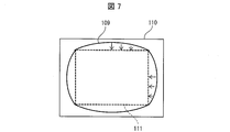
- FIG. 7 is a diagram for explaining image processing by the image processing unit.
- the image processing unit 102 digitally corrects distortion.
- the captured image of the imaging device 100 is smaller than that in the case where the distortion of the imaging lens 103 is not taken into consideration, and has a barrel shape.
- the captured image 109 of the imaging device 100 before image processing is smaller than the captured image 110 of the imaging device according to the related art that includes the imaging lens 108. It has a barrel shape.
- the image processing unit 102 performs image processing on the captured image 109 based on, for example, the following mathematical formula (1). Typically, the image processing unit 102 performs image processing on the output signal (electric signal) of the image sensor 104.
- IH (f ⁇ ⁇ max / tan ⁇ max ) ⁇ tan ⁇ (1) Note that IH is the size of a captured image. ⁇ max is the angle of view of the imaging apparatus 100 in the diagonal direction.
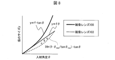
- FIG. 8 is a graph in which the concept of the size of each captured image shown in FIG. 7 is added to the graph shown in FIG.
- a thin solid line indicating the relationship between the incident angle of the imaging lens 103 and the image size can be considered as the size of the captured image 109, and a thick solid line indicating the same relationship of the imaging lens 108 is the size of the captured image 110.
- the size of the captured image 111 obtained by performing image processing on the captured image 109 can be represented by a dotted line shown in FIG.
- the image processing unit 102 can be realized by a device that performs simple image processing of, for example, the mathematical formula (1). For this reason, the image processing unit 102 only needs to perform a certain distortion correction process, and the burden on the image processing unit 102 is small. Therefore, the small and low-cost imaging device 100 can be realized.
- the size of the captured image can be reduced. For this reason, the data amount of a captured image becomes small.
- a margin of the effective image circle diameter with respect to the captured image can be secured, it is possible to perform appropriate correction for larger camera shake.
- the applied specifications are as follows.
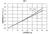
- FIG. 9 shows the characteristics of the size (vertical axis) of the captured image with respect to the incident angle (horizontal axis) for the imaging apparatus including the imaging lens according to the prior art and the imaging device including the imaging lens according to Embodiment 1. It is the graph which compared.
- IH f ⁇ tan ⁇
- FIG. 10 is a diagram illustrating a case where an image pickup apparatus including an image pickup lens according to the related art and an image pickup apparatus including the image pickup lens according to Embodiment 1 have a shake of 1 deg with respect to an incident angle (horizontal axis).
- 6 is a graph comparing the characteristics of the blurring amount (vertical axis) of a captured image after the correction of.
- FIG. 11 compares the distortion (vertical axis) characteristics with respect to the incident angle (horizontal axis) for the imaging apparatus including the imaging lens according to the related art and the imaging apparatus including the imaging lens according to the first embodiment. It is a graph.
- FIG. 12 is a graph in which characteristics relating to the captured image obtained by performing the image processing shown in the mathematical formula (1) are added to the graph shown in FIG.
- FIG. 13 is a diagram comparing grid chart imaging results for an imaging apparatus including an imaging lens according to the prior art and an imaging apparatus including an imaging lens according to Embodiment 1.
- FIG. 14 is a diagram comparing the imaging results of the grid chart before and after the image processing for the imaging apparatus including the imaging lens according to the first embodiment.
- the imaging device 100 and the camera module 101 provided with the imaging lens 103 are included in the scope of the present invention.
- Examples of the imaging apparatus 100 include imaging apparatuses such as a digital video camera and a digital still camera.
- Embodiment 2 In Embodiment 1, the example in which the OIS unit shifts the imaging lens 103 has been described. However, the imaging element 104 may be shifted, or both the imaging lens 103 and the imaging element 104 may be shifted. .
- FIG. 15 is a cross-sectional view for briefly explaining the configuration of the imaging apparatus according to the second embodiment and the function of the OIS unit in the imaging apparatus.
- the imaging apparatus 300 includes a lens holder and an OIS 306 instead of the lens holder and the OIS 106.
- the lens holder and OIS 306 have a lens holder part and an OIS part.
- the lens holder and the lens holder part of the OIS 306 are the same as the lens holder and the lens holder part of the OIS 106.
- the lens holder and the OIS unit of the OIS 306 shift the imaging element 104 in the normal direction ILn by moving the substrate 105 in the normal direction ILn with respect to the optical axis La of the imaging lens 103, for example.
- the direction of the normal direction ILn is opposite to the direction of the normal direction Ln.
- shifting the imaging element 104 in the normal direction ILn is synonymous with shifting the imaging lens 103 in the normal direction Ln.
- the camera module according to aspect 1 of the present invention includes an imaging lens, an imaging element that receives light that has passed through the imaging lens, and the imaging lens according to an angle at which a principal ray from a subject is incident on the imaging lens. And an optical camera shake correction mechanism (lens holder and OIS 106) that shifts at least one of the imaging elements in a direction normal to the optical axis of the imaging lens, and the size of an image formed by the imaging lens is Proportional to angle.
- an optical camera shake correction mechanism (lens holder and OIS 106) that shifts at least one of the imaging elements in a direction normal to the optical axis of the imaging lens, and the size of an image formed by the imaging lens is Proportional to angle.
- the distortion of the imaging lens is negative.
- the peripheral light amount ratio of the captured image can be increased, which is suitable for reducing noise caused by shading correction.
- the imaging lens is an f ⁇ lens.
- the imaging lens according to each aspect of the present invention can be easily realized.
- a camera module according to aspect 4 of the present invention is the camera module according to any one of the aspects 1 to 3, wherein the imaging lens includes at least one lens, and one of the lenses is directed toward the subject.
- the surface is concave, the central portion of the surface facing the image sensor is concave, and the surrounding portion surrounding the central portion is convex.
- An imaging device includes any one of the camera modules according to aspects 1 to 4.
- the imaging device includes the image processing unit according to aspect 5 that performs image processing on an output signal of the imaging element of the camera module.
- the image processing unit can be realized by a device that performs simple image processing. For this reason, the image processing unit only needs to perform a certain distortion correction process, and the burden on the image processing unit is small.
- the image processing unit reduces the size of the captured image of the imaging device based on the diagonal angle of view of the camera module and the angle. .
- the size of the captured image can be reduced. For this reason, the data amount of a captured image becomes small.
- a margin of the effective image circle diameter with respect to the captured image can be secured, it is possible to perform appropriate correction for larger camera shake.
- the present invention can be used for a camera module and an imaging apparatus having an OIS that shifts at least one of an imaging lens and an imaging element.
- the imaging device include imaging devices such as a digital video camera and a digital still camera.
- Imaging device 101
- Camera module 102
- Image processing part 103
- Imaging lens 104
- Imaging element 106
- Lens holder and OIS captured image 110
- captured image 111 captured image 200 subject 200c principal ray 200e principal ray L1 lens L2 lens La optical axis Ln normal direction c4 central portion p4 peripheral portion
Landscapes
- Physics & Mathematics (AREA)
- Engineering & Computer Science (AREA)
- Multimedia (AREA)
- Signal Processing (AREA)
- General Physics & Mathematics (AREA)
- Optics & Photonics (AREA)
- Studio Devices (AREA)
- Adjustment Of Camera Lenses (AREA)
- Lens Barrels (AREA)
- Lenses (AREA)
Abstract
Description
小型機器向けのカメラモジュールでは、撮像レンズを撮像素子に対してシフトさせる、レンズシフト方式のOISが多く用いられている。レンズシフト方式のOISは、手振れによって生じた被写体の像のシフトをキャンセルし、この像のブレを抑制する。
また、撮像レンズのディストーションをマイナスとすれば、撮像画像のサイズは小さくなる。これにより、撮像画像に対する有効像円径のマージンを確保することができるため、より大きな手振れに対し、適切な補正を行うことが可能となる。
〔撮像装置の構成〕
以下、説明の便宜上、先に説明した部材・変数と実質的に同じ機能を有する部材・変数については、一部、同じ符号を付記してその説明を省略している。
図3の(a)および(b)は、OIS部の機能の原理を説明する図であり、図3の(a)には補正前を、図3の(b)には補正後を示している。
図4の(a)は、従来技術に係る撮像レンズが形成する像を説明する図であり、図4の(b)は、実施の形態1に係る撮像レンズが形成する像を説明する図である。
図5は、実施の形態1に係る撮像装置による、格子チャートの撮像結果の一例を示す図である。なお、この格子チャートのアスペクト比は0.75である。
図7は、画像処理部による画像処理を説明する図である。
なお、IHとは、撮像画像のサイズである。また、θmaxとは、撮像装置100の対角方向の画角である。
13メガピクセル仕様の撮像レンズ108を備えた撮像装置と、同仕様の撮像装置100との各種特性を比較した。
・画素ピッチ:1.12μm
・最大画角:72deg
・最大像サイズ(像の中心から撮像素子の対角までの像のサイズ):2.9335mm
・焦点距離:4.038mm
・手振れ補正角度:1deg(撮像レンズの光軸に対して-1または+1deg)
以下、撮像レンズ108を備えた撮像装置に関する特性を「IH=f・tanθ」とし、撮像装置100に関する特性を「IH=f・θ」としている。
実施の形態1では、OIS部が、撮像レンズ103をシフトさせる例について説明を行ったが、撮像素子104をシフトさせてもよいし、撮像レンズ103および撮像素子104の両方をシフトさせてもよい。
本発明の態様1に係るカメラモジュールは、撮像レンズと、上記撮像レンズを通過した光を受光する撮像素子と、被写体からの主光線が上記撮像レンズに入射される角度に応じて、上記撮像レンズおよび上記撮像素子の少なくとも一方を、上記撮像レンズの光軸に対する法線方向にシフトさせる光学的手振れ補正機構(レンズホルダおよびOIS106)とを備えており、上記撮像レンズが形成する像のサイズが上記角度に比例する。
101 カメラモジュール
102 画像処理部
103 撮像レンズ
104 撮像素子
106 レンズホルダおよびOIS
109 撮像画像
110 撮像画像
111 撮像画像
200 被写体
200c 主光線
200e 主光線
L1 レンズ
L2 レンズ
La 光軸
Ln 法線方向
c4 中央部分
p4 周囲部分
Claims (6)
- 撮像レンズと、
上記撮像レンズを通過した光を受光する撮像素子と、
被写体からの主光線が上記撮像レンズに入射される角度に応じて、上記撮像レンズおよび上記撮像素子の少なくとも一方を、上記撮像レンズの光軸に対する法線方向にシフトさせる光学的手振れ補正機構とを備えており、
上記撮像レンズが形成する像のサイズが上記角度に比例することを特徴とするカメラモジュール。 - 上記撮像レンズのディストーションがマイナスとなっていることを特徴とする請求項1に記載のカメラモジュール。
- 上記撮像レンズは、fθレンズであることを特徴とする請求項1または2に記載のカメラモジュール。
- 上記撮像レンズは、少なくとも1つのレンズを有しており、
上記レンズのうち1つは、
上記被写体の側に向けた面が凹形状であり、
上記撮像素子の側に向けた面の中央部分が凹形状であると共に、上記中央部分を取り囲む周囲部分が凸形状であることを特徴とする請求項1から3のいずれか1項に記載のカメラモジュール。 - 請求項1から4のいずれか1項に記載のカメラモジュールを備えており、
上記カメラモジュールの上記撮像素子の出力信号に対して画像処理を施す画像処理部を有していることを特徴とする撮像装置。 - 上記画像処理部は、上記カメラモジュールの対角方向の画角および上記角度に基づいて、上記撮像装置の撮像画像のサイズを縮小することを特徴とする請求項5に記載の撮像装置。
Priority Applications (3)
| Application Number | Priority Date | Filing Date | Title |
|---|---|---|---|
| JP2016504996A JP6312799B2 (ja) | 2014-02-28 | 2014-11-17 | 撮像装置 |
| US15/117,212 US9888181B2 (en) | 2014-02-28 | 2014-11-17 | Camera module and image capturing apparatus with shake correction of image capturing lens or image sensor |
| CN201480076441.8A CN106030401B (zh) | 2014-02-28 | 2014-11-17 | 摄像模块和摄像装置 |
Applications Claiming Priority (2)
| Application Number | Priority Date | Filing Date | Title |
|---|---|---|---|
| JP2014-039536 | 2014-02-28 | ||
| JP2014039536 | 2014-02-28 |
Publications (1)
| Publication Number | Publication Date |
|---|---|
| WO2015129106A1 true WO2015129106A1 (ja) | 2015-09-03 |
Family
ID=54008450
Family Applications (1)
| Application Number | Title | Priority Date | Filing Date |
|---|---|---|---|
| PCT/JP2014/080363 Ceased WO2015129106A1 (ja) | 2014-02-28 | 2014-11-17 | カメラモジュールおよび撮像装置 |
Country Status (4)
| Country | Link |
|---|---|
| US (1) | US9888181B2 (ja) |
| JP (1) | JP6312799B2 (ja) |
| CN (1) | CN106030401B (ja) |
| WO (1) | WO2015129106A1 (ja) |
Cited By (1)
| Publication number | Priority date | Publication date | Assignee | Title |
|---|---|---|---|---|
| CN108700799A (zh) * | 2016-01-06 | 2018-10-23 | 派纳维景国际股份有限公司 | 数字成像的变形摄影 |
Families Citing this family (2)
| Publication number | Priority date | Publication date | Assignee | Title |
|---|---|---|---|---|
| US10539764B2 (en) | 2017-07-05 | 2020-01-21 | Panavision International, L.P. | Anamorphic photography and squeeze ratios for digital imagers |
| JP7672194B2 (ja) * | 2019-08-22 | 2025-05-07 | キヤノン株式会社 | 像ブレ補正装置及びその制御方法、プログラム、記憶媒体 |
Citations (4)
| Publication number | Priority date | Publication date | Assignee | Title |
|---|---|---|---|---|
| JPH10233950A (ja) * | 1996-12-17 | 1998-09-02 | Eriko Shimizu | 電子ズーム画像入力方式 |
| JP2004358550A (ja) * | 2003-06-09 | 2004-12-24 | Sumitomo Heavy Ind Ltd | レーザ加工方法およびレーザ加工装置 |
| JP2007121650A (ja) * | 2005-10-27 | 2007-05-17 | Sony Corp | ズームレンズ及び撮像装置 |
| JP2009531723A (ja) * | 2006-03-29 | 2009-09-03 | テセラ・テクノロジーズ・ハンガリー・ケイエフティー | 画質が改良された撮像装置 |
Family Cites Families (16)
| Publication number | Priority date | Publication date | Assignee | Title |
|---|---|---|---|---|
| US4848882A (en) * | 1986-03-25 | 1989-07-18 | Canon Kabushiki Kaisha | Gradient index lens |
| US5446581A (en) * | 1993-03-15 | 1995-08-29 | Lockheed Missiles & Space Co., Inc. | Inverted telephoto wide-aperture wide-field infrared lens system |
| JP4706105B2 (ja) * | 2001-01-09 | 2011-06-22 | 株式会社ニコン | 撮影装置 |
| CN1332231C (zh) * | 2002-07-01 | 2007-08-15 | 罗姆股份有限公司 | 图像传感器组件 |
| JP4022595B2 (ja) * | 2004-10-26 | 2007-12-19 | コニカミノルタオプト株式会社 | 撮影装置 |
| JP2006129175A (ja) | 2004-10-29 | 2006-05-18 | Fuji Photo Film Co Ltd | 撮像装置 |
| JP4026641B2 (ja) * | 2004-12-03 | 2007-12-26 | 日産自動車株式会社 | 物体検出装置、および物体検出方法 |
| KR100674838B1 (ko) * | 2005-02-28 | 2007-01-26 | 삼성전기주식회사 | 적층형 카메라 모듈 |
| KR100703469B1 (ko) * | 2005-07-07 | 2007-04-03 | 삼성전자주식회사 | 촬상용 광학계 |
| JP5164504B2 (ja) * | 2007-10-01 | 2013-03-21 | キヤノン株式会社 | 撮像装置 |
| CN101964871B (zh) * | 2009-07-21 | 2013-08-28 | 鸿富锦精密工业(深圳)有限公司 | 防抖装置以及手机 |
| JP5031876B2 (ja) | 2010-09-24 | 2012-09-26 | シャープ株式会社 | カメラモジュールおよび撮像装置 |
| CN103403603B (zh) * | 2010-12-16 | 2015-09-09 | 富士胶片株式会社 | 变焦镜头和成像设备 |
| US20140184854A1 (en) * | 2012-12-28 | 2014-07-03 | Motorola Mobility Llc | Front camera face detection for rear camera zoom function |
| KR101425793B1 (ko) * | 2012-12-31 | 2014-08-06 | 주식회사 코렌 | 촬영 렌즈 광학계 |
| TWI570387B (zh) * | 2015-11-09 | 2017-02-11 | 財團法人工業技術研究院 | 影像測距系統、光源模組及影像感測模組 |
-
2014
- 2014-11-17 JP JP2016504996A patent/JP6312799B2/ja not_active Expired - Fee Related
- 2014-11-17 CN CN201480076441.8A patent/CN106030401B/zh not_active Expired - Fee Related
- 2014-11-17 WO PCT/JP2014/080363 patent/WO2015129106A1/ja not_active Ceased
- 2014-11-17 US US15/117,212 patent/US9888181B2/en not_active Expired - Fee Related
Patent Citations (4)
| Publication number | Priority date | Publication date | Assignee | Title |
|---|---|---|---|---|
| JPH10233950A (ja) * | 1996-12-17 | 1998-09-02 | Eriko Shimizu | 電子ズーム画像入力方式 |
| JP2004358550A (ja) * | 2003-06-09 | 2004-12-24 | Sumitomo Heavy Ind Ltd | レーザ加工方法およびレーザ加工装置 |
| JP2007121650A (ja) * | 2005-10-27 | 2007-05-17 | Sony Corp | ズームレンズ及び撮像装置 |
| JP2009531723A (ja) * | 2006-03-29 | 2009-09-03 | テセラ・テクノロジーズ・ハンガリー・ケイエフティー | 画質が改良された撮像装置 |
Cited By (2)
| Publication number | Priority date | Publication date | Assignee | Title |
|---|---|---|---|---|
| CN108700799A (zh) * | 2016-01-06 | 2018-10-23 | 派纳维景国际股份有限公司 | 数字成像的变形摄影 |
| CN108700799B (zh) * | 2016-01-06 | 2021-08-03 | 派纳维景国际股份有限公司 | 数字成像的变形摄影 |
Also Published As
| Publication number | Publication date |
|---|---|
| CN106030401B (zh) | 2019-10-11 |
| JPWO2015129106A1 (ja) | 2017-03-30 |
| US9888181B2 (en) | 2018-02-06 |
| JP6312799B2 (ja) | 2018-04-18 |
| US20160360112A1 (en) | 2016-12-08 |
| CN106030401A (zh) | 2016-10-12 |
Similar Documents
| Publication | Publication Date | Title |
|---|---|---|
| JP5031876B2 (ja) | カメラモジュールおよび撮像装置 | |
| JP5103977B2 (ja) | フレキシブル基板、手振れ補正ユニットおよび撮像装置 | |
| US20210242250A1 (en) | Solid-state imaging device and electronic apparatus | |
| JP5968169B2 (ja) | 撮像装置、その制御方法、および制御プログラム | |
| US11867877B2 (en) | Lens module and electronic device | |
| JP3924546B2 (ja) | 撮像装置 | |
| JP6312799B2 (ja) | 撮像装置 | |
| JP2016197663A (ja) | 撮像素子及び撮像装置 | |
| JP2009272890A (ja) | 画像処理装置及び画像処理方法、並びに撮影装置 | |
| JP2017044876A (ja) | 撮像装置及び像ブレ補正方法 | |
| US20150264265A1 (en) | Camera module | |
| JP5712031B2 (ja) | 撮像装置、撮影レンズユニット、および撮像ユニット | |
| JP6335671B2 (ja) | 像振れ補正装置および像振れ補正方法 | |
| CN108429872B (zh) | 用于校正图像渐晕的方法、成像装置及成像系统 | |
| KR20200014204A (ko) | 제어장치, 촬상장치, 및 기억매체 | |
| WO2013172030A1 (ja) | 撮像装置、撮影レンズユニット、および撮像ユニット | |
| US20110205639A1 (en) | Imaging lens and imaging module | |
| JP6061503B2 (ja) | 画像処理方法、画像処理装置および撮像装置 | |
| JP4998092B2 (ja) | 固体撮像回路およびカメラシステム | |
| JP2012049892A (ja) | 撮像装置 | |
| US10321025B2 (en) | Mobile device with folding optical elements | |
| US9380211B2 (en) | Image stabilization using light sensors | |
| JP6269200B2 (ja) | カメラ装置 | |
| US20140285688A1 (en) | Optical system of electrical equipment, electrical equipment, and optical function complementary processing circuit | |
| JP2017063393A (ja) | 撮像素子、及びカメラ |
Legal Events
| Date | Code | Title | Description |
|---|---|---|---|
| 121 | Ep: the epo has been informed by wipo that ep was designated in this application |
Ref document number: 14884166 Country of ref document: EP Kind code of ref document: A1 |
|
| ENP | Entry into the national phase |
Ref document number: 2016504996 Country of ref document: JP Kind code of ref document: A |
|
| WWE | Wipo information: entry into national phase |
Ref document number: 15117212 Country of ref document: US |
|
| NENP | Non-entry into the national phase |
Ref country code: DE |
|
| 122 | Ep: pct application non-entry in european phase |
Ref document number: 14884166 Country of ref document: EP Kind code of ref document: A1 |