WO2015128925A1 - Oil separator - Google Patents

Oil separator Download PDF

Info

Publication number
WO2015128925A1
WO2015128925A1 PCT/JP2014/054426 JP2014054426W WO2015128925A1 WO 2015128925 A1 WO2015128925 A1 WO 2015128925A1 JP 2014054426 W JP2014054426 W JP 2014054426W WO 2015128925 A1 WO2015128925 A1 WO 2015128925A1
Authority
WO
WIPO (PCT)
Prior art keywords
oil
gas
spindle
lower case
oil separator
Prior art date
Application number
PCT/JP2014/054426
Other languages
French (fr)
Japanese (ja)
Inventor
耕作 石田
毅 八百
Original Assignee
東京濾器株式会社
Priority date (The priority date is an assumption and is not a legal conclusion. Google has not performed a legal analysis and makes no representation as to the accuracy of the date listed.)
Filing date
Publication date
Application filed by 東京濾器株式会社 filed Critical 東京濾器株式会社
Priority to EP14883775.0A priority Critical patent/EP3112032B1/en
Priority to US15/121,660 priority patent/US20160375387A1/en
Priority to PCT/JP2014/054426 priority patent/WO2015128925A1/en
Priority to JP2016504875A priority patent/JP6255476B2/en
Publication of WO2015128925A1 publication Critical patent/WO2015128925A1/en

Links

Images

Classifications

    • BPERFORMING OPERATIONS; TRANSPORTING
    • B01PHYSICAL OR CHEMICAL PROCESSES OR APPARATUS IN GENERAL
    • B01DSEPARATION
    • B01D45/00Separating dispersed particles from gases or vapours by gravity, inertia, or centrifugal forces
    • B01D45/12Separating dispersed particles from gases or vapours by gravity, inertia, or centrifugal forces by centrifugal forces
    • B01D45/14Separating dispersed particles from gases or vapours by gravity, inertia, or centrifugal forces by centrifugal forces generated by rotating vanes, discs, drums or brushes
    • BPERFORMING OPERATIONS; TRANSPORTING
    • B04CENTRIFUGAL APPARATUS OR MACHINES FOR CARRYING-OUT PHYSICAL OR CHEMICAL PROCESSES
    • B04BCENTRIFUGES
    • B04B11/00Feeding, charging, or discharging bowls
    • B04B11/02Continuous feeding or discharging; Control arrangements therefor
    • BPERFORMING OPERATIONS; TRANSPORTING
    • B04CENTRIFUGAL APPARATUS OR MACHINES FOR CARRYING-OUT PHYSICAL OR CHEMICAL PROCESSES
    • B04BCENTRIFUGES
    • B04B5/00Other centrifuges
    • B04B5/005Centrifugal separators or filters for fluid circulation systems, e.g. for lubricant oil circulation systems
    • BPERFORMING OPERATIONS; TRANSPORTING
    • B04CENTRIFUGAL APPARATUS OR MACHINES FOR CARRYING-OUT PHYSICAL OR CHEMICAL PROCESSES
    • B04BCENTRIFUGES
    • B04B5/00Other centrifuges
    • B04B5/12Centrifuges in which rotors other than bowls generate centrifugal effects in stationary containers
    • FMECHANICAL ENGINEERING; LIGHTING; HEATING; WEAPONS; BLASTING
    • F01MACHINES OR ENGINES IN GENERAL; ENGINE PLANTS IN GENERAL; STEAM ENGINES
    • F01MLUBRICATING OF MACHINES OR ENGINES IN GENERAL; LUBRICATING INTERNAL COMBUSTION ENGINES; CRANKCASE VENTILATING
    • F01M13/00Crankcase ventilating or breathing
    • F01M13/04Crankcase ventilating or breathing having means for purifying air before leaving crankcase, e.g. removing oil
    • BPERFORMING OPERATIONS; TRANSPORTING
    • B04CENTRIFUGAL APPARATUS OR MACHINES FOR CARRYING-OUT PHYSICAL OR CHEMICAL PROCESSES
    • B04BCENTRIFUGES
    • B04B5/00Other centrifuges
    • B04B5/12Centrifuges in which rotors other than bowls generate centrifugal effects in stationary containers
    • B04B2005/125Centrifuges in which rotors other than bowls generate centrifugal effects in stationary containers the rotors comprising separating walls
    • FMECHANICAL ENGINEERING; LIGHTING; HEATING; WEAPONS; BLASTING
    • F01MACHINES OR ENGINES IN GENERAL; ENGINE PLANTS IN GENERAL; STEAM ENGINES
    • F01MLUBRICATING OF MACHINES OR ENGINES IN GENERAL; LUBRICATING INTERNAL COMBUSTION ENGINES; CRANKCASE VENTILATING
    • F01M13/00Crankcase ventilating or breathing
    • F01M13/04Crankcase ventilating or breathing having means for purifying air before leaving crankcase, e.g. removing oil
    • F01M2013/0422Separating oil and gas with a centrifuge device

Definitions

  • the present invention relates to an oil separator that separates mist oil contained in a gas to be treated from gas.
  • an oil separator that separates mist oil contained in a gas to be treated from gas.
  • an oil separator disclosed in Patent Document 1 includes a cylindrical fixed housing and a cylindrical fixed casing having a ceiling portion, and a truncated cone-shaped partition having an opening on the upper surface, and a lower chamber (lower storage chamber).
  • the upper chamber (upper accommodation chamber) is partitioned.
  • a centrifugal rotor for purifying oil is disposed in the lower chamber, and a gas purifying device for purifying gas is disposed in the upper chamber.
  • the lower end of the fixed housing is joined to the base, and the lower chamber communicates with the internal space of the cylindrical base.
  • the cylindrical base is communicated with the combustion engine, and the purified oil is returned and gas from the crankcase is introduced.
  • the centrifugal rotor and the gas purification device are connected by a tubular support member, and are configured to be rotatable around a fixed shaft inserted through the support member.
  • a separation chamber is provided inside the centrifugal rotor. Oil is supplied to the separation chamber through a gap between the support member and the fixed shaft and a hole opened in the support member. The supplied oil is purified in the separation chamber and then discharged to the side through a discharge port provided on the bottom surface of the centrifugal rotor. The oil discharge generates a driving force for rotating the centrifugal rotor and the gas purification device.
  • the above-mentioned oil separator has a vertically long structure because a centrifuge rotor is arranged in the lower chamber and an oil discharge port is provided at the lower end of the centrifuge rotor. For this reason, even if the conventional oil separator is mounted on a vehicle such as a truck, the height from the oil outlet to the opening of the partition can be sufficiently secured. Therefore, even if the oil separator is tilted, it is unlikely that a problem occurs.
  • the centrifuge rotor in the lower chamber.
  • a communication portion with the combustion engine that is, an oil discharge passage and a gas introduction passage are arranged immediately below the partition.
  • an oil outlet is also arranged immediately below the partition. If the oil separator is tilted in this configuration, the oil may be undulated by the gas introduced from the engine and flow into the upper chamber beyond the partition. Then, due to the inflow of oil, the rotational speed of the gas purification device disposed in the upper chamber may decrease, and the gas purification performance may be impaired.
  • the present invention has been made in view of such circumstances, and its purpose is to suppress the oil undulation caused by the introduced gas even when the oil separator is inclined, and to maintain the gas purification performance at a high level. There is to do.
  • the present invention provides an oil separator for separating mist-like oil contained in a gas to be processed, which is provided so as to be rotatable together with a spindle, and is stacked in the axial direction of the spindle.
  • a separation disk, a nozzle projecting from a peripheral surface below the separation disk in the spindle, and a nozzle for rotating the spindle about an axis by injecting oil from an injection hole, and the processing target gas are introduced.
  • a gas introduction part a lower case provided with an oil discharge part for discharging oil, and a storage chamber that is attached to the lower case from above and accommodates the spindle, the separation disk, and the nozzle
  • An upper case that is partitioned together with the lower case, and the storage chamber is partitioned into a lower storage chamber and an upper storage chamber, and the lower case
  • the gas inlet inlet end of the processing object gas faces the outside of the lower case, and the gas outlet inlet end of the gas to be processed is constituted by a cylindrical member facing the lower side of the nozzle.
  • the gas introduction part provided in the lower case is constituted by the cylindrical member, the introduction inlet end faces the outside of the lower case, and the introduction outlet end faces the lower side of the nozzle. Therefore, the undulation of the oil flowing through the oil discharge part can be suppressed by introducing the gas to be treated by the gas introduction part. Thereby, even if the oil separator is inclined, the inflow of oil into the upper storage chamber can be prevented, and the gas purification performance can be maintained at a high level.
  • the spindle is rotatably supported by a spindle shaft, and the lower case is provided with a joint portion into which the lower end portion of the spindle shaft is fitted, and the gas introduction portion on the inlet / outlet side Preferably, the portion is provided along the joint portion.
  • the processing target gas can be introduced into the upper storage chamber from the rotation center side with respect to the trajectory of the injection hole.
  • the spindle shaft may be configured by a cylindrical member that supplies oil serving as power for the spindle
  • the joint portion may be configured by a cylindrical member that supplies the oil to the spindle shaft.
  • the rigidity of the joint portion that partitions the oil supply flow path can be increased by the introduction outlet side portion.
  • the inlet / outlet end of the gas to be processed is within a height range below the injection hole height by the rotation diameter d of the injection hole, and within a rotation diameter range of 1.5 d. It is preferable to make it face. In this configuration, the inlet / outlet end faces the predetermined range with respect to the nozzle, so that even if the oil separator is tilted, oil can be reliably prevented from flowing into the upper storage chamber.
  • the partition member is a ring-shaped plate member that is inclined downward toward the outer peripheral side, and the oil sprayed from the injection holes is sprayed onto a downwardly inclined surface. In this configuration, the injected oil flows downward, and mixing of the oil into the treated gas can be suppressed.
  • the apparatus when the introduction inlet side portion of the gas introduction part is provided in parallel with the oil discharge part, the apparatus can be miniaturized.
  • an oil separator that separates mist-like oil contained in a gas to be treated from gas, even if the oil separator is tilted, the oil rippling due to the introduced gas is suppressed, and the gas purification performance is high. Can be maintained at a level.
  • FIG. 1 a closed crankcase ventilation system 1 (hereinafter referred to as a ventilation system 1) shown in FIG. 1 will be described as an example.
  • the ventilation system 1 has an oil separator 2 and a breather pipe 3.
  • the oil separator 2 processes blow-by gas (corresponding to a processing target gas containing mist-like oil) discharged from the engine, and separates the mist-like oil.
  • the oil separator 2 is attached to the side surface of the engine 4.
  • the breather pipe 3 defines a reduction passage for reducing the treated blow-by gas discharged from the oil separator 2 to the intake-side passage 5 of the engine 4.
  • blow-by gas discharged from the engine 4 is introduced into an oil separator 2 provided on the side of the engine 4. Then, the oil separated by the oil separator 2 is returned to the engine 4.
  • the treated blow-by gas is discharged from the upper end of the oil separator 2 and then returned to the intake-side flow path 5 through the breather pipe 3. Specifically, it is reduced to a portion where the air filter 6 and the turbocharger 7 are connected in the intake side flow path 5.
  • the reduced blow-by gas is mixed with fresh air from the air filter 6 and compressed by the turbocharger 7. Thereafter, it is cooled by the charge cooler 8 and supplied to the engine 4.
  • the oil separator 2 includes a housing 11 having a lower case 12 and an upper case 13. Various components such as a rotor unit and a PCV valve are accommodated in an internal space (accommodating chamber) of the housing 11 (described later).
  • the lower case 12 is a portion that divides the lower portion of the housing 11, and is configured by a box-shaped member having a bottom and an open upper surface.
  • the lower case 12 and the communication tube portion are made of a casting, but may be made by molding a resin.
  • a circular fitting portion 14 is provided at the upper end portion of the lower case 12 and is fitted to the lower end portion 15 of the upper case 13.
  • a communication cylinder portion 16 that communicates with the engine 4 is provided facing rearward.
  • a cylindrical member 17 (see FIG. 3), which will be described later, is provided in the vicinity of the communication cylinder portion 16. This cylindrical member 17 functions as a gas introduction part into which blowby gas is introduced.
  • the communication cylinder part 16 functions as an oil discharge part from which the separated oil is discharged.
  • a flange 18 that is coupled to the side surface of the engine 4 is provided at the distal end portion of the communication tube portion 16.
  • the lower end portion of the joint portion 19 projects downward from the bottom surface of the lower case 12.
  • the joint portion 19 has a cylindrical shape and is connected to one end of the oil supply pipe 9 shown in FIG. As will be described later, a part of the joint portion 19 protrudes upward in the lower case 12.
  • the other end of the oil supply pipe 9 is connected to the side surface of the engine 4, and oil is supplied to the oil supply pipe 9 from an oil passage (not shown) provided inside the engine 4. This oil is used as power for rotating the rotor unit 21 shown in FIG.
  • the upper case 13 is a member attached to the lower case 12 from above, and divides the accommodation chamber in which the rotor unit 21 and the like are accommodated together with the lower case 12.
  • the upper case 13 has a cylindrical main body cover 22 and a disk-shaped upper surface cover 23.
  • a plurality of vertical ribs 24 are formed on the inner surface of the main body cover 22 at equal intervals in the circumferential direction. These vertical ribs 24 are used to capture and unite the separated oil flowing in the circumferential direction along the inner surface of the main body cover 22 and to flow downward.
  • the upper surface cover 23 is attached to the upper end portion of the main body cover 22 in an airtight state.
  • a cylindrical gas discharge portion 25 is provided at the center of the top cover 23 so as to face upward.
  • the gas discharge part 25 is a part for discharging the blow-by gas after processing, and the breather pipe 3 is connected via the outlet pipe 26.
  • a rotor unit 21 and a partition member 27 are disposed inside the oil separator 2. Further, as shown in the cross-sectional view of FIG. 5, a PCV valve 28 is attached inside the upper surface cover 23.
  • the rotor unit 21 is a mechanism for separating mist-like oil contained in blow-by gas, and has a rotor 31, a spindle 32, and a spindle shaft 33 as shown in FIG.
  • the rotor 31 is a part that aggregates mist-like oil by rotation and separates it from blow-by gas, and includes a plurality of separation disks 34, an upper holder 35, and a lower holder 36.
  • the separation disk 34 is a ring-shaped plate material that is inclined downward toward the outer peripheral side, in other words, a plate material that is processed into a side surface shape of a truncated cone.
  • the separation disk 34 of the present embodiment has a thickness of 1 mm or less and is manufactured by resin molding. These separation disks 34 are stacked in the axial direction of the spindle 32. For convenience of explanation, the separation disks 34 are drawn with an interval between them, but the actual interval is set to be extremely narrow (for example, less than 1 mm).
  • the upper holder 35 is a member that holds a plurality of stacked separation disks 34 from above, and the lower holder 36 is also a member that holds the separation disk 34 from below.
  • a plurality of connecting arms 36a for connecting to the upper holder 35 are provided on the outer peripheral edge of the lower holder 36 (see FIG. 4). In the present embodiment, four connection arms 36a are provided at intervals of 90 degrees in the circumferential direction.
  • the rotor 31 has a cylindrical appearance. As shown in FIG. 5, the inner peripheral side is a hollow portion and penetrates in the vertical direction. A spindle 32 is inserted into the hollow portion, and the spindle 32 and the rotor 31 are coupled to each other. For this reason, the rotor 31 rotates around the axis of the spindle 32 together with the spindle 32.
  • a nozzle 37 projects from the peripheral surface of the spindle 32 below the rotor 31.
  • the nozzle 37 is a portion that injects oil supplied through the spindle shaft 33, and generates a driving force for rotating the spindle 32 and the rotor 31.
  • the nozzle 37 of the present embodiment has a cylindrical nozzle body 38 whose base end is joined to the spindle 32 and whose tip is closed, and an injection hole 39 provided at the tip of the nozzle body 38. .
  • the nozzle body 38 is attached at an angle of 45 degrees obliquely downward with respect to the axial direction of the spindle 32 indicated by reference numeral AL.
  • Three nozzle bodies 38 are provided at intervals of 120 degrees in the circumferential direction.
  • the injection hole 39 is provided on the side surface of the tip portion of the nozzle body 38. Specifically, the injection hole 39 is provided in a direction orthogonal to the axial direction of the nozzle main body 38 indicated by reference numeral NL and in a direction in which oil is injected in the horizontal direction.
  • the spindle shaft 33 is a cylindrical member serving as a bearing for the spindle 32, and supports the spindle 32 in a rotatable state. As shown in FIG. 5, an oil supply path 33 a for supplying oil is formed inside the spindle shaft 33.
  • the lower end portion of the spindle shaft 33 is joined to the upper end portion of the joint portion 19 provided in the lower case 12.
  • the oil supply pipe 9 is connected to the joint portion 19. For this reason, the oil supplied through the oil supply pipe 9 flows into the spindle shaft 33 after passing through the joint portion 19. Further, after flowing into the nozzle main body 38, it is injected from the injection hole 39.
  • the injection hole 39 is provided at the tip of the nozzle body 38 in a direction in which oil is injected in the horizontal direction. And in the three nozzles 37 provided at intervals of 120 degrees, the formation positions of the injection holes 39 are aligned. For this reason, when oil is injected from each injection hole 39, the rotor 31 and the spindle 32 rotate around the spindle shaft 33.
  • the partition member 27 partitions the internal space (storage chamber) of the housing 11 into a lower storage chamber 41 (primary separation chamber) and an upper storage chamber 42 (secondary separation chamber). It is a member that forms a communication port 43 that guides the blow-by gas in the side storage chamber 41 to the upper storage chamber 42.
  • the partition member 27 has an outer peripheral portion 44 and a tapered portion 45.
  • the outer peripheral portion 44 is a portion having a short cylindrical shape, and a flange portion 46 projects laterally in the middle of the height direction.
  • the tapered portion 45 is provided on the inner peripheral side with respect to the outer peripheral portion 44, and has a tapered shape that is gradually reduced in diameter from the lower end of the outer peripheral portion 44 upward.
  • the tapered portion 45 of the present embodiment has an inclined surface 45 a that is inclined at an angle of about 45 degrees with respect to the axis of the spindle 32.
  • the upper end opening of the tapered portion 45 forms a communication port 43.
  • the partition member 27 is fitted into the fitting portion 14 of the lower case 12 from the inner peripheral side. Then, the flange portion 46 is positioned in contact with the upper end of the fitting portion 14 from above. As a result, the tapered portion 45 is disposed immediately below the lower holder 36 included in the rotor 31. Then, with the partition member 27 as a boundary, the storage chamber is partitioned into a lower storage chamber 41 and an upper storage chamber 42, and the lower storage chamber 41 and the upper storage chamber 42 communicate with each other through the communication port 43. That is, the partition member 27 forms a communication port 43 for guiding the blow-by gas in the lower storage chamber 41 to the upper storage chamber 42 around the spindle 32 at a height between the nozzle 37 and the separation disk 34.
  • the lower storage chamber 41 functions as a primary separation chamber for mist oil.
  • the PCV valve 28 includes a diaphragm 47, an upper spring 48, and a lower spring 49.
  • the diaphragm 47 is a valve body, which is manufactured by molding rubber and resin, and is configured by a disk-shaped member that is slightly inclined downward from the central portion toward the peripheral portion.
  • the upper spring 48 and the lower spring 49 are members for supporting the diaphragm 47 in a state in which the diaphragm 47 can move in the vertical direction. That is, the upper spring 48 is disposed at the center of the diaphragm 47 from above, and the lower spring 49 is disposed at the center of the diaphragm 47 from below.
  • the diaphragm 47 is sandwiched between the upper spring 48 and the lower spring 49 so as to be supported so as to be movable in the vertical direction.
  • the PCV valve 28 is disposed on the upper case 13. Specifically, it is arranged at a position directly below the upper surface cover 23 in a state of being placed on the pedestal 51.
  • the pedestal 51 is airtightly covered with a diaphragm 47.
  • a lower spring 49 is attached between the pedestal 51 and the diaphragm 47. Further, the space defined by the pedestal 51 and the diaphragm 47 is open to the atmosphere through the air communication part 52.
  • an upper spring 48 is attached between the upper surface cover 23 and the diaphragm 47.
  • the diaphragm 47 moves up and down according to the intake side pressure of the engine 4 and the internal pressure of the crankcase, and adjusts the flow of blow-by gas. That is, the diaphragm 47 moves to the gas discharge unit 25 side (upward) when the intake pressure (negative pressure) of the engine 4 is excessively large, and to the opposite side (downward) when the crankcase side pressure is high. Moving.
  • the outer periphery of the pedestal 51 on which the PCV valve 28 is placed is partitioned by a side wall having a circular shape in plan view, and a communication window 53 is provided on the side wall.
  • a communication window portion 53 By this communication window portion 53, a portion above the diaphragm 47 in the upper accommodation chamber 42 and a portion on the rotor 31 side are communicated with each other.
  • a cylindrical rib 54 is provided below the side wall.
  • the cylindrical rib 54 is a ring-shaped protrusion provided integrally with the main body cover 22 at a height above the rotor unit 21 and below the diaphragm 47.
  • the cylindrical rib 54 guides fluid (oil or blow-by gas) flowing downward from the outer peripheral side to the inner peripheral side along the inner surface of the main body cover 22 at the upper end of the main body cover 22. Since the amount of oil can also be reduced by this cylindrical rib 54, the adhesion of oil to the PCV valve 28 can be suppressed at a high level.
  • a cylindrical joint portion 19 protrudes upward in the internal space of the lower case 12.
  • a part of the cylindrical member 17 is provided along the joint portion 19.
  • the tubular member 17 is bent in an L shape in the middle, and the remaining portion is provided in parallel with the communication tubular portion 16.
  • the cylindrical member 17 is provided immediately above the communicating cylinder portion 16, and an end portion thereof protrudes from the flange 18.
  • the fixed frame 55 is a metal frame attached to the fitting portion 14 of the lower case 12 (see FIG. 4).
  • the cylindrical member 17 has a blow-by gas introduction inlet side portion 17a projecting behind the flange 18 (right side in FIG. 9) and an introduction outlet side portion 17b in the vicinity of the joint portion 19 and fixed. It is arranged immediately below the frame 55.
  • the opening width of the introduction outlet side portion 17 b is sufficiently wider than the width of the frame constituting the fixed frame 55.
  • the opening area of the introduction outlet side portion 17b and the opening area of the outlet pipe 26 are aligned, and the blow-by gas flows smoothly.
  • the blow-by gas discharged from the cylindrical member 17 flows upward through the fixed frame 55 and flows into the hollow portion of the rotor 31 from the rotation center side with respect to the locus of the injection holes 39.
  • the introduction outlet side portion 17b of the cylindrical member 17 gas introduction portion
  • the opening faces the lower side of the nozzle 37, specifically, as indicated by the dotted line X in FIG.
  • the blow-by gas can be efficiently flowed into the hollow portion of the rotor 31 as long as it faces.
  • the blow-by gas discharged from the cylindrical member 17 can be introduced into the upper storage chamber 42 from the rotation center side with respect to the locus of the injection hole 39 while suppressing the entrainment of the oil injected from the injection hole 39.
  • the oil injected from the nozzle 37 (injection hole 39) is collected at the bottom of the lower housing chamber 41 together with the oil separated from the blow-by gas, and is returned to the engine 4 through the communication cylinder portion 16.
  • the flow path of blow-by gas is partitioned by the cylindrical member 17, the flow of oil is hardly affected by the flow of blow-by gas.
  • the oil supplied from the engine 4 to the joint portion 19 through the oil supply pipe 9 flows into the spindle shaft 33 as indicated by the arrow F1. Thereafter, the oil flows from the spindle shaft 33 into the nozzle body 38 and is injected from the injection hole 39 as indicated by the arrow F2.
  • the rotor 31 and the spindle 32 rotate around the spindle shaft 33.
  • the injected oil is sprayed onto the tapered portion 45 of the partition member 27 and is guided in the obliquely downward direction on the outer peripheral side along the inclined surface 45a of the tapered portion 45, as indicated by the arrow F3. Thereby, mixing of the oil splash into the blow-by gas can be suppressed. Thereafter, the oil flows down the inner surface of the lower case 12 toward the bottom of the lower storage chamber 41 as indicated by an arrow F4. Further, the oil flows into the communication cylinder portion 16 and is returned from the side surface of the engine 4 to the crankcase as indicated by an arrow F5.
  • blow-by gas from the engine 4 is guided by the tubular member 17 as indicated by an arrow F11. Thereafter, as indicated by the arrow F12, the blow-by gas discharged from the inlet / outlet side portion 17b flows into the hollow portion of the rotor 31 through the inside of the movement locus of the injection hole 39. Since the cylindrical member 17 forms an independent flow path, the oil flow is hardly affected by the blow-by gas flow.
  • blow-by gas that has flowed into the hollow portion of the rotor 31 moves through the gap between the separation disks 34 toward the outer periphery of the rotor 31 by the centrifugal force generated as the rotor 31 rotates, as indicated by the arrow F13.
  • the pressure on the inner circumferential side of the rotor 31 becomes lower than the pressure on the outer circumferential side. This pressure difference makes it easier for the blow-by gas in the lower housing chamber 41 to flow into the hollow portion of the rotor 31, so that the inflow efficiency of the blow-by gas can be increased.
  • the blow-by gas comes into contact with the separation disk 34, mist-like oil contained in the blow-by gas adheres to the surface of the separation disk 34. Then, another mist-like oil is combined with the attached mist-like oil, and the oil is aggregated on the surface of the separation disk 34. That is, the oil is secondarily separated.
  • the blow-by gas is primarily separated from the mist-like oil in the lower housing chamber 41. For this reason, the mist oil is separated from the blow-by gas at a high level by the secondary separation in the separation disk 34.
  • the upper storage chamber 42 corresponds to a secondary separation chamber that secondary-separates the remaining mist-like oil with respect to the blow-by gas after the mist-like oil is primarily separated.
  • a gap SP is formed between the spindle 32 and the spindle shaft 33.
  • This gap functions as an oil guide path and is filled with oil supplied to be ejected from the nozzle 37.
  • the supply pressure of the oil is sufficiently high, a part of the oil filled in the gap is discharged from the upper end portion of the spindle 32 to the hollow portion of the rotor 31 through the upper end of the gap.
  • the oil discharged into the hollow portion of the rotor 31 moves in the gap between the separation disks 34 in the outer circumferential direction of the rotor 31 by the centrifugal force of the rotor 31 as in the blow-by gas.
  • the oil aggregated on the surface of the separation disk 34 is combined with the oil discharged into the hollow portion of the rotor 31. As a result, the surface of the separation disk 34 is cleaned, and maintenance for the separation disk 34 can be simplified. Oil agglomerated or coalesced on the surface of the separation disk 34 is discharged from the outer peripheral edge of the separation disk 34, collides with the inner surface of the main body cover 22, and then flows down the inner surface. Further, the oil merges with the oil injected from the nozzle 37 in the lower accommodation chamber 41 and is returned to the engine 4.
  • the blow-by gas from which the mist-like oil has been separated after passing through the rotor 31 rises while turning around the gap between the inner surface of the upper case 13 and the rotor 31 in the upper storage chamber 42.
  • the separated oil rises on the swirling flow of blow-by gas. Then, it flows down along the vertical ribs 24. Even if the oil flows from the outer peripheral side to the inner peripheral side along the inner surface of the main body cover 22, the oil can be dropped in the form of droplets by the cylindrical rib 54.
  • the blowby gas from which the mist-like oil has been separated is guided to the space on the upper surface side of the PCV valve 28 as indicated by the arrows F14 and F15. Thereafter, as indicated by an arrow F ⁇ b> 16, the air is guided to the breather pipe 3 through the outlet pipe 26.
  • the independent flow path for blow-by gas is formed by the cylindrical member 17, even if it inclines forward as shown, for example in FIG.
  • the oil OL accumulated in the tank is not undulated by the flow of blow-by gas. Thereby, oil can be prevented from entering the rotor 31 side, and the gas purification performance can be maintained at a high level.
  • the separation disk 34 is composed of a ring-shaped plate material that is inclined downward toward the outer peripheral side, so that the oil separated by the separation disk 34 flows downward. , It is possible to suppress oil from being mixed into the treated gas.
  • the inflow side portion of the cylindrical member 17 gas inflow portion
  • the communication cylinder portion 16 oil discharge portion
  • the upper end portion of the joint portion 19 and the lower end portion of the spindle shaft 33 are supported by the fixed frame 55.
  • the fixed frame 55 may be omitted. This is because the rigidity of the joint portion 19 is improved because the discharge side portion of the cylindrical member 17 (gas inflow portion) is provided integrally with the joint portion 19.
  • the introduction inlet side portion 17a in the cylindrical member 17 ′ (gas inflow portion) is located at a position different from the communicating cylinder portion 16 (oil discharge portion) in the lower case 12, specifically May project forward from the front surface of the lower case 12.
  • the protruding position of the introduction inlet side portion 17a is not limited to the front surface of the lower case 12, and may be either the left or right side surface.
  • SYMBOLS 1 Closed-type crankcase ventilation system, 2 ... Oil separator, 3 ... Breather pipe, 4 ... Engine, 5 ... Intake side flow path, 6 ... Air filter, 7 ... Turbocharger, 8 ... Charge cooler, 9 ... Oil supply pipe , 11 ... Housing, 12 ... Lower case, 13 ... Upper case, 14 ... Lower case fitting part, 15 ... Lower end part of upper case, 16 ... Communication cylinder part, 17, 17 '... Cylindrical member, 17a ... inlet side portion of the cylindrical member, 17b ... inlet side portion of the cylindrical member, 18 ... flange, 19 ... joint portion, 21 ... rotor unit, 22 ... main body cover, 23 ...

Abstract

 The purpose of the present invention is to minimize oil rippling caused by gas that has been led in and to maintain a high level of gas purification performance, even when an oil separator is inclined. This oil separator (2) has: a plurality of separation discs (34) provided to be capable of rotating with a spindle (32), the separation discs being stacked on the spindle; a nozzle (37) for rotating the spindle by spraying oil; a cylindrical member (17) for leading in a blow-by gas; a lower case (12) provided with a communication cylinder (16) for discharging separated oil; an upper case (13) attached to the lower case from above, the upper case forming an accommodation chamber; and a dividing member (27) for dividing the accommodation chamber into a lower accommodation chamber and an upper accommodation chamber, and forming a communication port (43) in the periphery of the spindle at a height between the nozzle and the separation discs, the communication port guiding the blow-by gas. The inlet entrance for the blow-by gas in the cylindrical member (17) faces the outside of the lower case, and the inlet exit faces the lower vicinity of the nozzle.

Description

オイルセパレータOil separator
 本発明は、処理対象ガスに含まれるミスト状オイルをガスから分離するオイルセパレータに関する。 The present invention relates to an oil separator that separates mist oil contained in a gas to be treated from gas.
 処理対象ガスに含まれるミスト状オイルをガスから分離するオイルセパレータが知られている。例えば、特許文献1に記載のオイルセパレータは、円筒状の固定ハウジング及び天井部を有する円筒状の固定ケーシングと、上面に開口を有する円錐台状の仕切りにより、下部チャンバ(下側収容室)と上部チャンバ(上側収容室)を区画している。下部チャンバにはオイルを浄化するための遠心分離ローターが配置され、上部チャンバにはガスを浄化するためのガス浄化装置が配置されている。また、固定ハウジングの下端は基部に接合されており、下部チャンバが筒状基部の内部空間に連通されている。この筒状基部は、燃焼機関に連通されており、浄化後のオイルが戻されると共にクランクケースからのガスが導入される。 An oil separator that separates mist oil contained in a gas to be treated from gas is known. For example, an oil separator disclosed in Patent Document 1 includes a cylindrical fixed housing and a cylindrical fixed casing having a ceiling portion, and a truncated cone-shaped partition having an opening on the upper surface, and a lower chamber (lower storage chamber). The upper chamber (upper accommodation chamber) is partitioned. A centrifugal rotor for purifying oil is disposed in the lower chamber, and a gas purifying device for purifying gas is disposed in the upper chamber. The lower end of the fixed housing is joined to the base, and the lower chamber communicates with the internal space of the cylindrical base. The cylindrical base is communicated with the combustion engine, and the purified oil is returned and gas from the crankcase is introduced.
 遠心分離ローター及びガス浄化装置は、管状の支持部材によって連結されており、支持部材に挿通された固定シャフトを中心に回転可能に構成されている。遠心分離ローターの内部には分離チャンバが設けられている。この分離チャンバには、支持部材と固定シャフトの隙間及び支持部材に開口された穴を通じてオイルが供給される。供給されたオイルは、分離チャンバで浄化された後、遠心分離ローターの底面に設けられた排出口を通じて側方に排出される。オイルの排出によって、遠心分離ローター及びガス浄化装置を回転させるための駆動力が発生される。 The centrifugal rotor and the gas purification device are connected by a tubular support member, and are configured to be rotatable around a fixed shaft inserted through the support member. A separation chamber is provided inside the centrifugal rotor. Oil is supplied to the separation chamber through a gap between the support member and the fixed shaft and a hole opened in the support member. The supplied oil is purified in the separation chamber and then discharged to the side through a discharge port provided on the bottom surface of the centrifugal rotor. The oil discharge generates a driving force for rotating the centrifugal rotor and the gas purification device.
 クランクケースからのガスは、下部チャンバにおける固定ハウジングと遠心分離ローターとの隙間に下方から流入して上昇し、仕切りの上面に設けられた開口を通じて上部チャンバに流入する。そして、ガス浄化装置で浄化された後、固定ケーシングの天井部に上方へ突設された排出口を通じて排出される。 ¡Gas from the crankcase flows into the gap between the fixed housing and the centrifugal rotor in the lower chamber from below, rises, and flows into the upper chamber through an opening provided on the upper surface of the partition. And after purifying with a gas purification apparatus, it discharges | emits through the discharge port projected upwards in the ceiling part of the fixed casing.
特表2005-515065号公報JP 2005-515065 gazette
 前述のオイルセパレータでは、下部チャンバに遠心分離ローターが配置され、かつ、遠心分離ローターの下端にオイルの排出口が設けられているので、縦長構造を採っている。このため、従来のオイルセパレータをトラック等の車両に搭載しても、オイルの排出口から仕切りの開口までの高さを十分に確保できる。従って、オイルセパレータが傾斜されても不具合は生じ難いと考えられる。 The above-mentioned oil separator has a vertically long structure because a centrifuge rotor is arranged in the lower chamber and an oil discharge port is provided at the lower end of the centrifuge rotor. For this reason, even if the conventional oil separator is mounted on a vehicle such as a truck, the height from the oil outlet to the opening of the partition can be sufficiently secured. Therefore, even if the oil separator is tilted, it is unlikely that a problem occurs.
 ここで、オイルセパレータを小型化するため、下部チャンバの遠心分離ローターをなくすことが考えられる。遠心分離ローターをなくすと、燃焼機関との連通部、すなわちオイルの排出路及びガスの導入路が仕切りの直下に配置される。さらに、オイルの排出口も仕切りの直下に配置される。この構成においてオイルセパレータが傾斜されると、エンジンから導入されたガスによってオイルが波打ち、仕切りを超えて上部チャンバ内に流入する可能性がある。そして、オイルの流入により、上部チャンバ内に配置されたガス浄化装置の回転数が低下し、ガスの浄化性能が損なわれてしまう虞がある。 Here, in order to reduce the size of the oil separator, it is conceivable to eliminate the centrifuge rotor in the lower chamber. When the centrifuge rotor is eliminated, a communication portion with the combustion engine, that is, an oil discharge passage and a gas introduction passage are arranged immediately below the partition. Further, an oil outlet is also arranged immediately below the partition. If the oil separator is tilted in this configuration, the oil may be undulated by the gas introduced from the engine and flow into the upper chamber beyond the partition. Then, due to the inflow of oil, the rotational speed of the gas purification device disposed in the upper chamber may decrease, and the gas purification performance may be impaired.
 本発明は、このような事情に鑑みてなされたものであり、その目的は、オイルセパレータが傾斜されても、導入されたガスによるオイルの波打ちを抑制し、ガスの浄化性能を高いレベルで維持することにある。 The present invention has been made in view of such circumstances, and its purpose is to suppress the oil undulation caused by the introduced gas even when the oil separator is inclined, and to maintain the gas purification performance at a high level. There is to do.
 前述の目的を達成するため、本発明は、処理対象ガスに含まれるミスト状オイルを分離するオイルセパレータであって、スピンドルと共に回転可能に設けられ、前記スピンドルの軸線方向に積層された複数枚の分離ディスクと、前記スピンドルにおける前記分離ディスクよりも下側の周面から突設され、噴射孔からオイルを噴射させることで軸線を中心に前記スピンドルを回転させるノズルと、前記処理対象ガスを導入するガス導入部、及び、オイルを排出させるオイル排出部が設けられた下側ケースと、前記下側ケースに上方から取り付けられ、前記スピンドル、前記分離ディスク、及び前記ノズルが収容される収容室を、前記下側ケースと共に区画する上側ケースと、前記収容室を、下側収容室と上側収容室とに区画し、かつ、前記下側収容室の前記処理対象ガスを前記上側収容室に案内する連通口を、前記ノズルと前記分離ディスクの間の高さにおける前記スピンドルの周囲に形成する区画部材とを有し、前記ガス導入部は、前記処理対象ガスの導入入口端部が、前記下側ケースの外に臨み、前記処理対象ガスの導入出口端部が、前記ノズルの下側近傍に臨む筒状部材によって構成されていることを特徴とする。 In order to achieve the above-mentioned object, the present invention provides an oil separator for separating mist-like oil contained in a gas to be processed, which is provided so as to be rotatable together with a spindle, and is stacked in the axial direction of the spindle. A separation disk, a nozzle projecting from a peripheral surface below the separation disk in the spindle, and a nozzle for rotating the spindle about an axis by injecting oil from an injection hole, and the processing target gas are introduced. A gas introduction part, a lower case provided with an oil discharge part for discharging oil, and a storage chamber that is attached to the lower case from above and accommodates the spindle, the separation disk, and the nozzle, An upper case that is partitioned together with the lower case, and the storage chamber is partitioned into a lower storage chamber and an upper storage chamber, and the lower case A partition member that forms a communication port for guiding the processing target gas in the storage chamber to the upper storage chamber around the spindle at a height between the nozzle and the separation disk; The gas inlet inlet end of the processing object gas faces the outside of the lower case, and the gas outlet inlet end of the gas to be processed is constituted by a cylindrical member facing the lower side of the nozzle. Features.
 本発明によれば、下側ケースに設けられるガス導入部が筒状部材によって構成され、導入入口端部が下側ケースの外に臨み、導入出口端部がノズルの下側近傍に臨んでいるので、処理対象ガスをガス導入部によって導入することで、オイル排出部を流れるオイルの波打ちを抑制できる。これにより、オイルセパレータが傾斜されても、上側収容室へのオイルの流入を防止でき、ガスの浄化性能を高いレベルで維持することができる。 According to the present invention, the gas introduction part provided in the lower case is constituted by the cylindrical member, the introduction inlet end faces the outside of the lower case, and the introduction outlet end faces the lower side of the nozzle. Therefore, the undulation of the oil flowing through the oil discharge part can be suppressed by introducing the gas to be treated by the gas introduction part. Thereby, even if the oil separator is inclined, the inflow of oil into the upper storage chamber can be prevented, and the gas purification performance can be maintained at a high level.
 前述のオイルセパレータにおいて、前記スピンドルを、スピンドルシャフトによって回転可能に支持し、前記下側ケースには、前記スピンドルシャフトの下端部が嵌合されるジョイント部を設け、前記ガス導入部の導入出口側部分を、前記ジョイント部に沿って設けることが好ましい。この構成では、処理対象ガスを、噴射孔の軌跡よりも回転中心側から上側収容室へ導入できる。 In the oil separator described above, the spindle is rotatably supported by a spindle shaft, and the lower case is provided with a joint portion into which the lower end portion of the spindle shaft is fitted, and the gas introduction portion on the inlet / outlet side Preferably, the portion is provided along the joint portion. In this configuration, the processing target gas can be introduced into the upper storage chamber from the rotation center side with respect to the trajectory of the injection hole.
 前述のオイルセパレータにおいて、前記スピンドルシャフトを、前記スピンドルの動力となるオイルを供給する円筒状部材によって構成し、前記ジョイント部を、前記スピンドルシャフトに前記オイルを供給する筒状部材によって構成することが好ましい。この構成では、オイルの供給流路を区画するジョイント部の剛性を、導入出口側部分によって高めることができる。 In the above oil separator, the spindle shaft may be configured by a cylindrical member that supplies oil serving as power for the spindle, and the joint portion may be configured by a cylindrical member that supplies the oil to the spindle shaft. preferable. In this configuration, the rigidity of the joint portion that partitions the oil supply flow path can be increased by the introduction outlet side portion.
 前述のオイルセパレータにおいて、前記処理対象ガスの導入出口端部を、前記噴射孔の高さから当該噴射孔の回転直径dだけ下方の高さ範囲内であって、1.5dの回転直径範囲内に臨ませることが好ましい。この構成では、導入出口端部がノズルを基準とする所定範囲内に臨んでいるので、オイルセパレータが傾斜されても、上側収容室へのオイルの流入を確実に防止できる。 In the oil separator described above, the inlet / outlet end of the gas to be processed is within a height range below the injection hole height by the rotation diameter d of the injection hole, and within a rotation diameter range of 1.5 d. It is preferable to make it face. In this configuration, the inlet / outlet end faces the predetermined range with respect to the nozzle, so that even if the oil separator is tilted, oil can be reliably prevented from flowing into the upper storage chamber.
 前述のオイルセパレータにおいて、前記区画部材を、外周側に向けて下り傾斜されたリング状の板材とし、下り傾斜面に前記噴射孔から噴射された前記オイルが吹き付けられる構成とすることが好ましい。この構成では、噴射されたオイルが下向きに流れることとなり、処理後ガスへのオイルの混入を抑制できる。 In the above-described oil separator, it is preferable that the partition member is a ring-shaped plate member that is inclined downward toward the outer peripheral side, and the oil sprayed from the injection holes is sprayed onto a downwardly inclined surface. In this configuration, the injected oil flows downward, and mixing of the oil into the treated gas can be suppressed.
 前述のオイルセパレータにおいて、前記ガス導入部の導入入口側部分が、前記オイル排出部と並行に設けられている場合には、装置の小型化が図れる。 In the above-described oil separator, when the introduction inlet side portion of the gas introduction part is provided in parallel with the oil discharge part, the apparatus can be miniaturized.
 前述のオイルセパレータにおいて、前記ガス導入部の導入入口側部分が、前記下側ケースにおける前記オイル排出部とは異なる位置から、前記下側ケースよりも外側に突設されている場合には、処理対象ガスの導入経路に対する自由度が向上する。 In the above-described oil separator, when the introduction inlet side portion of the gas introduction part protrudes outside the lower case from a position different from the oil discharge part in the lower case, The degree of freedom for the target gas introduction route is improved.
 本発明によれば、処理対象ガスに含まれるミスト状オイルをガスから分離するオイルセパレータにおいて、オイルセパレータが傾斜されても、導入されたガスによるオイルの波打ちを抑制し、ガスの浄化性能を高いレベルで維持することができる。 According to the present invention, in an oil separator that separates mist-like oil contained in a gas to be treated from gas, even if the oil separator is tilted, the oil rippling due to the introduced gas is suppressed, and the gas purification performance is high. Can be maintained at a level.
閉鎖型クランクケース換気システムを示す概略図である。It is the schematic which shows a closed type crankcase ventilation system. オイルセパレータを前方斜め上方から見た斜視図である。It is the perspective view which looked at the oil separator from the front diagonally upper direction. オイルセパレータを後方斜め下方から見た斜視図である。It is the perspective view which looked at the oil separator from back diagonally downward. オイルセパレータの分解斜視図である。It is a disassembled perspective view of an oil separator. オイルセパレータにおける上側半部の断面図である。It is sectional drawing of the upper half part in an oil separator. 下側ケースを前方斜め上方から見た斜視図である。It is the perspective view which looked at the lower case from front diagonally upward. 下側ケースを後方斜め上方から見た斜視図である。It is the perspective view which looked at the lower case from back diagonally upward. 下側ケースに設けられたフランジ、連通筒部(オイル排出部)、及び筒状部材(ガス導入部)を説明する図である。It is a figure explaining the flange provided in the lower case, a communication cylinder part (oil discharge part), and a cylindrical member (gas introduction part). 下側ケースの断面図である。It is sectional drawing of a lower case. ブローバイバス及びオイルの流れを説明する図である。It is a figure explaining the flow of a blow-by bath and oil. オイルセパレータが前方に傾倒した状態におけるブローバイバス及びオイルの流れを説明する図である。It is a figure explaining the flow of a blow-by bath and oil in the state where the oil separator inclined forward. 固定フレームを省略した第1変形例を説明する要部断面図である。It is principal part sectional drawing explaining the 1st modification which abbreviate | omitted the fixed frame. 筒状部材の導入入口側部分を、下側ケースの前面から前方に突出させた第2変形例を説明する図であり、下側ケースを前方斜め下方から見た斜視図である。It is a figure explaining the 2nd modification which made the introduction entrance side part of a cylindrical member project ahead from the front of a lower case, and is a perspective view which looked at the lower case from the front slanting lower part. 第2変形例を説明する図であり、下側ケースを前方斜め上方から見た斜視図である。It is a figure explaining a 2nd modification, and is the perspective view which looked at the lower case from the front diagonal upper part. 第2変形例を説明する要部断面図である。It is principal part sectional drawing explaining a 2nd modification.
 以下、本発明の実施形態を図面に基づいて説明する。ここでは、図1に示す閉鎖型クランクケース換気システム1(以下、換気システム1という。)を例に挙げて説明する。 Hereinafter, embodiments of the present invention will be described with reference to the drawings. Here, a closed crankcase ventilation system 1 (hereinafter referred to as a ventilation system 1) shown in FIG. 1 will be described as an example.
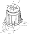
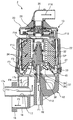
 同図に示すように、換気システム1は、オイルセパレータ2とブリーザーパイプ3とを有する。オイルセパレータ2は、エンジンから排出されたブローバイガス(ミスト状オイルを含有する処理対象ガスに相当する。)を処理し、ミスト状オイルを分離する。本実施形態において、オイルセパレータ2はエンジン4の側面に取り付けられている。ブリーザーパイプ3は、オイルセパレータ2から排出された処理後のブローバイガスを、エンジン4の吸気側流路5に還元するための還元流路を区画する。 As shown in the figure, the ventilation system 1 has an oil separator 2 and a breather pipe 3. The oil separator 2 processes blow-by gas (corresponding to a processing target gas containing mist-like oil) discharged from the engine, and separates the mist-like oil. In the present embodiment, the oil separator 2 is attached to the side surface of the engine 4. The breather pipe 3 defines a reduction passage for reducing the treated blow-by gas discharged from the oil separator 2 to the intake-side passage 5 of the engine 4.
 この換気システム1において、エンジン4から排出されたブローバイガスは、エンジン4の側面に設けられたオイルセパレータ2に導入される。そして、オイルセパレータ2で分離されたオイルはエンジン4へと戻される。一方、処理後のブローバイガスは、オイルセパレータ2の上端部から排出された後、ブリーザーパイプ3を通じて吸気側流路5に還元される。具体的には、吸気側流路5におけるエアフィルタ6とターボチャージャー7とを接続する部分に還元される。還元されたブローバイガスは、エアフィルタ6からの新鮮な空気と混合され、ターボチャージャー7で圧縮される。その後、チャージクーラー8で冷却されて、エンジン4に供給される。 In this ventilation system 1, blow-by gas discharged from the engine 4 is introduced into an oil separator 2 provided on the side of the engine 4. Then, the oil separated by the oil separator 2 is returned to the engine 4. On the other hand, the treated blow-by gas is discharged from the upper end of the oil separator 2 and then returned to the intake-side flow path 5 through the breather pipe 3. Specifically, it is reduced to a portion where the air filter 6 and the turbocharger 7 are connected in the intake side flow path 5. The reduced blow-by gas is mixed with fresh air from the air filter 6 and compressed by the turbocharger 7. Thereafter, it is cooled by the charge cooler 8 and supplied to the engine 4.
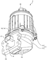
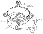
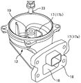
 次に、オイルセパレータ2について説明する。図2及び図3に示すように、このオイルセパレータ2では、下側ケース12と上側ケース13を有するハウジング11を有している。ハウジング11の内部空間(収容室)に、ローターユニットやPCVバルブといった各種の部品が収容されている(後述する)。 Next, the oil separator 2 will be described. As shown in FIGS. 2 and 3, the oil separator 2 includes a housing 11 having a lower case 12 and an upper case 13. Various components such as a rotor unit and a PCV valve are accommodated in an internal space (accommodating chamber) of the housing 11 (described later).
 下側ケース12は、ハウジング11の下側部分を区画する部分であり、上面が開放された有底の箱状部材によって構成されている。本実施形態において、下側ケース12や連通筒部等は鋳物で作製されているが、樹脂を成型することで作製してもよい。 The lower case 12 is a portion that divides the lower portion of the housing 11, and is configured by a box-shaped member having a bottom and an open upper surface. In the present embodiment, the lower case 12 and the communication tube portion are made of a casting, but may be made by molding a resin.
 図4に示すように、下側ケース12の上端部には円形の嵌合部14が設けられており、上側ケース13の下端部15と嵌め合わされる。下側ケース12の背面には、エンジン4と連通する連通筒部16が後方に向けて設けられている。この連通筒部16の近傍には、後述する筒状部材17(図3を参照)が設けられている。この筒状部材17は、ブローバイガスが導入されるガス導入部として機能する。一方、連通筒部16は、分離後のオイルが排出されるオイル排出部として機能する。そして、連通筒部16の先端部には、エンジン4の側面に結合されるフランジ18が設けられている。 As shown in FIG. 4, a circular fitting portion 14 is provided at the upper end portion of the lower case 12 and is fitted to the lower end portion 15 of the upper case 13. On the back surface of the lower case 12, a communication cylinder portion 16 that communicates with the engine 4 is provided facing rearward. A cylindrical member 17 (see FIG. 3), which will be described later, is provided in the vicinity of the communication cylinder portion 16. This cylindrical member 17 functions as a gas introduction part into which blowby gas is introduced. On the other hand, the communication cylinder part 16 functions as an oil discharge part from which the separated oil is discharged. A flange 18 that is coupled to the side surface of the engine 4 is provided at the distal end portion of the communication tube portion 16.
 下側ケース12の底面には、ジョイント部19の下端部が下向きに突設されている。このジョイント部19は円筒状をしており、図1に示すオイル供給パイプ9の一端に接続されている。後述するように、ジョイント部19の一部は、下側ケース12の内部で上方に突設されている。オイル供給パイプ9の他端はエンジン4の側面に接続されており、オイル供給パイプ9には、エンジン4の内部に設けられた油路(図示せず)からオイルが供給される。このオイルは、図4に示すローターユニット21を回転させるための動力として用いられる。 The lower end portion of the joint portion 19 projects downward from the bottom surface of the lower case 12. The joint portion 19 has a cylindrical shape and is connected to one end of the oil supply pipe 9 shown in FIG. As will be described later, a part of the joint portion 19 protrudes upward in the lower case 12. The other end of the oil supply pipe 9 is connected to the side surface of the engine 4, and oil is supplied to the oil supply pipe 9 from an oil passage (not shown) provided inside the engine 4. This oil is used as power for rotating the rotor unit 21 shown in FIG.
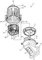
 図2~図4に示すように、上側ケース13は、下側ケース12に上方から取り付けられる部材であり、ローターユニット21などが収容される収容室を下側ケース12と共に区画する。この上側ケース13は、円筒状の本体カバー22と円盤状の上面カバー23とを有している。本体カバー22の内表面には複数本の縦リブ24が円周方向に等間隔で形成されている。これらの縦リブ24は、本体カバー22の内表面に沿って周方向に流れる分離後のオイルを捕捉及び合体させて、下方へ流下させるためのものである。 As shown in FIGS. 2 to 4, the upper case 13 is a member attached to the lower case 12 from above, and divides the accommodation chamber in which the rotor unit 21 and the like are accommodated together with the lower case 12. The upper case 13 has a cylindrical main body cover 22 and a disk-shaped upper surface cover 23. A plurality of vertical ribs 24 are formed on the inner surface of the main body cover 22 at equal intervals in the circumferential direction. These vertical ribs 24 are used to capture and unite the separated oil flowing in the circumferential direction along the inner surface of the main body cover 22 and to flow downward.
 図2に示すように、上面カバー23は、本体カバー22の上端部に気密状態で取り付けられている。また、上面カバー23の中心部には、筒状のガス排出部25が上方に向けて設けられている。このガス排出部25は、処理後のブローバイガスを排出する部分であり、出口パイプ26を介してブリーザーパイプ3が接続される。 As shown in FIG. 2, the upper surface cover 23 is attached to the upper end portion of the main body cover 22 in an airtight state. A cylindrical gas discharge portion 25 is provided at the center of the top cover 23 so as to face upward. The gas discharge part 25 is a part for discharging the blow-by gas after processing, and the breather pipe 3 is connected via the outlet pipe 26.
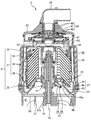
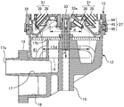
 次に、オイルセパレータ2の内部構造について説明する。図4に示すように、オイルセパレータ2の内部には、ローターユニット21や区画部材27が配設されている。また、図5の断面図に示すように、上面カバー23の内部には、PCVバルブ28が取り付けられている。 Next, the internal structure of the oil separator 2 will be described. As shown in FIG. 4, a rotor unit 21 and a partition member 27 are disposed inside the oil separator 2. Further, as shown in the cross-sectional view of FIG. 5, a PCV valve 28 is attached inside the upper surface cover 23.
 まず、ローターユニット21について説明する。このローターユニット21は、ブローバイガスに含まれるミスト状オイルを分離するための機構であり、図5に示すように、ローター31、スピンドル32、及びスピンドルシャフト33を有している。 First, the rotor unit 21 will be described. The rotor unit 21 is a mechanism for separating mist-like oil contained in blow-by gas, and has a rotor 31, a spindle 32, and a spindle shaft 33 as shown in FIG.
 ローター31は、回転によってミスト状オイルを凝集させ、ブローバイガスから分離する部分であり、複数枚の分離ディスク34、上部ホルダ35、及び下部ホルダ36を有している。分離ディスク34は、外周側に向けて下り傾斜されたリング状の板材、言い換えれば円錐台の側面形状に加工された板材である。本実施形態の分離ディスク34は、厚さが1mm以下とされ、樹脂の成型により作製されている。これらの分離ディスク34は、スピンドル32の軸線方向に積層されている。なお、説明の都合上、分離ディスク34同士の間隔を空けて描いているが、実際の間隔は極めて狭く(例えば1mm未満)に定められている。 The rotor 31 is a part that aggregates mist-like oil by rotation and separates it from blow-by gas, and includes a plurality of separation disks 34, an upper holder 35, and a lower holder 36. The separation disk 34 is a ring-shaped plate material that is inclined downward toward the outer peripheral side, in other words, a plate material that is processed into a side surface shape of a truncated cone. The separation disk 34 of the present embodiment has a thickness of 1 mm or less and is manufactured by resin molding. These separation disks 34 are stacked in the axial direction of the spindle 32. For convenience of explanation, the separation disks 34 are drawn with an interval between them, but the actual interval is set to be extremely narrow (for example, less than 1 mm).
 上部ホルダ35は、積層された複数枚の分離ディスク34を上側から保持する部材であり、下部ホルダ36は、同じく下側から保持する部材である。そして、下部ホルダ36の外周縁には、上部ホルダ35と連結するための連結アーム36aが複数本設けられている(図4を参照)。本実施形態では、4本の連結アーム36aが周方向に90度間隔で設けられている。連結アーム36aの上端を上部ホルダ35に接合することで、複数枚の分離ディスク34、上部ホルダ35、及び下部ホルダ36が一体化されてローター31が構成される。 The upper holder 35 is a member that holds a plurality of stacked separation disks 34 from above, and the lower holder 36 is also a member that holds the separation disk 34 from below. A plurality of connecting arms 36a for connecting to the upper holder 35 are provided on the outer peripheral edge of the lower holder 36 (see FIG. 4). In the present embodiment, four connection arms 36a are provided at intervals of 90 degrees in the circumferential direction. By joining the upper end of the connecting arm 36 a to the upper holder 35, the plurality of separation disks 34, the upper holder 35, and the lower holder 36 are integrated to form the rotor 31.
 このローター31は、円筒状の外観をしており、図5に示すように、内周側が中空部分とされて上下方向に貫通している。この中空部分にはスピンドル32が挿入されており、スピンドル32とローター31とは互いに結合されている。このためローター31は、スピンドル32と共にスピンドル32の軸線を中心に回転する。 The rotor 31 has a cylindrical appearance. As shown in FIG. 5, the inner peripheral side is a hollow portion and penetrates in the vertical direction. A spindle 32 is inserted into the hollow portion, and the spindle 32 and the rotor 31 are coupled to each other. For this reason, the rotor 31 rotates around the axis of the spindle 32 together with the spindle 32.
 スピンドル32におけるローター31よりも下側の周面からはノズル37が突設されている。このノズル37は、スピンドルシャフト33を通じて供給されたオイルを噴射する部分であり、スピンドル32やローター31を回転させるための駆動力を発生させる。 A nozzle 37 projects from the peripheral surface of the spindle 32 below the rotor 31. The nozzle 37 is a portion that injects oil supplied through the spindle shaft 33, and generates a driving force for rotating the spindle 32 and the rotor 31.
 本実施形態のノズル37は、基端がスピンドル32に接合され、先端が塞がれた円筒状のノズル本体38と、ノズル本体38の先端部に設けられた噴射孔39とを有している。ノズル本体38は、符号ALで示すスピンドル32の軸線方向に対して下向き斜め45度の角度で取り付けられている。そして、3本のノズル本体38が周方向に120度間隔で設けられている。また、噴射孔39は、ノズル本体38における先端部の側面に設けられている。詳しくは、噴射孔39は、符号NLで示すノズル本体38の軸線方向と直交する向きであって、オイルが水平方向に噴射される向きに設けられている。 The nozzle 37 of the present embodiment has a cylindrical nozzle body 38 whose base end is joined to the spindle 32 and whose tip is closed, and an injection hole 39 provided at the tip of the nozzle body 38. . The nozzle body 38 is attached at an angle of 45 degrees obliquely downward with respect to the axial direction of the spindle 32 indicated by reference numeral AL. Three nozzle bodies 38 are provided at intervals of 120 degrees in the circumferential direction. The injection hole 39 is provided on the side surface of the tip portion of the nozzle body 38. Specifically, the injection hole 39 is provided in a direction orthogonal to the axial direction of the nozzle main body 38 indicated by reference numeral NL and in a direction in which oil is injected in the horizontal direction.
 スピンドルシャフト33は、スピンドル32の軸受けとなる円柱状部材であり、スピンドル32を回転可能な状態で支持する。図5に示すように、スピンドルシャフト33の内側には、オイルを供給するためのオイル供給路33aが形成されている。また、スピンドルシャフト33の下端部は、下側ケース12に設けられたジョイント部19の上端部と接合されている。前述したように、ジョイント部19には、オイル供給パイプ9が接続されている。このため、オイル供給パイプ9を通じて供給されたオイルは、ジョイント部19を通った後にスピンドルシャフト33へ流入する。さらに、ノズル本体38に流入した後に噴射孔39から噴射される。 The spindle shaft 33 is a cylindrical member serving as a bearing for the spindle 32, and supports the spindle 32 in a rotatable state. As shown in FIG. 5, an oil supply path 33 a for supplying oil is formed inside the spindle shaft 33. The lower end portion of the spindle shaft 33 is joined to the upper end portion of the joint portion 19 provided in the lower case 12. As described above, the oil supply pipe 9 is connected to the joint portion 19. For this reason, the oil supplied through the oil supply pipe 9 flows into the spindle shaft 33 after passing through the joint portion 19. Further, after flowing into the nozzle main body 38, it is injected from the injection hole 39.
 前述したように噴射孔39は、ノズル本体38の先端部において、オイルが水平方向に噴射される向きに設けられている。そして、120度間隔で設けられた3本のノズル37において、噴射孔39の形成位置は揃えられている。このため、各噴射孔39からオイルが噴射されると、ローター31及びスピンドル32は、スピンドルシャフト33を軸にして回転する。 As described above, the injection hole 39 is provided at the tip of the nozzle body 38 in a direction in which oil is injected in the horizontal direction. And in the three nozzles 37 provided at intervals of 120 degrees, the formation positions of the injection holes 39 are aligned. For this reason, when oil is injected from each injection hole 39, the rotor 31 and the spindle 32 rotate around the spindle shaft 33.
 次に、区画部材27について説明する。図5に示すように、区画部材27は、ハウジング11の内部空間(収容室)を下側収容室41(一次分離室)と上側収容室42(二次分離室)とに区画すると共に、下側収容室41のブローバイガスを上側収容室42へ案内する連通口43を形成する部材である。図4及び図5に示すように、区画部材27は、外周部44とテーパー部45とを有している。外周部44は、短尺な円筒状をした部分であり、高さ方向の中間には鍔部46が側方に張り出している。テーパー部45は、外周部44よりも内周側に設けられており、外周部44の下端から上方に向けて次第に縮径されたテーパー形状をしている。本実施形態のテーパー部45は、スピンドル32の軸線に対して約45度の角度で傾斜する傾斜面45aを有している。そして、テーパー部45の上端開口が連通口43を形成している。 Next, the partition member 27 will be described. As shown in FIG. 5, the partition member 27 partitions the internal space (storage chamber) of the housing 11 into a lower storage chamber 41 (primary separation chamber) and an upper storage chamber 42 (secondary separation chamber). It is a member that forms a communication port 43 that guides the blow-by gas in the side storage chamber 41 to the upper storage chamber 42. As shown in FIGS. 4 and 5, the partition member 27 has an outer peripheral portion 44 and a tapered portion 45. The outer peripheral portion 44 is a portion having a short cylindrical shape, and a flange portion 46 projects laterally in the middle of the height direction. The tapered portion 45 is provided on the inner peripheral side with respect to the outer peripheral portion 44, and has a tapered shape that is gradually reduced in diameter from the lower end of the outer peripheral portion 44 upward. The tapered portion 45 of the present embodiment has an inclined surface 45 a that is inclined at an angle of about 45 degrees with respect to the axis of the spindle 32. The upper end opening of the tapered portion 45 forms a communication port 43.
 区画部材27は、下側ケース12の嵌合部14に対して内周側から嵌め込まれる。そして、鍔部46が嵌合部14の上端に上方から当接して位置決めされる。その結果、テーパー部45は、ローター31が有する下部ホルダ36の直下に配置される。そして、区画部材27を境にして、収容室は下側収容室41と上側収容室42とに区画され、これらの下側収容室41と上側収容室42とが連通口43を通じて連通される。すなわち、この区画部材27によって、下側収容室41のブローバイガスを上側収容室42に案内する連通口43が、ノズル37と分離ディスク34の間の高さにおけるスピンドル32の周囲に形成される。 The partition member 27 is fitted into the fitting portion 14 of the lower case 12 from the inner peripheral side. Then, the flange portion 46 is positioned in contact with the upper end of the fitting portion 14 from above. As a result, the tapered portion 45 is disposed immediately below the lower holder 36 included in the rotor 31. Then, with the partition member 27 as a boundary, the storage chamber is partitioned into a lower storage chamber 41 and an upper storage chamber 42, and the lower storage chamber 41 and the upper storage chamber 42 communicate with each other through the communication port 43. That is, the partition member 27 forms a communication port 43 for guiding the blow-by gas in the lower storage chamber 41 to the upper storage chamber 42 around the spindle 32 at a height between the nozzle 37 and the separation disk 34.
 また、ローター31の高速回転時において、噴射孔39の旋回軌道から外周側には、高速で旋回するオイルの膜が形成される。このオイルの膜にブローバイガスが接触すると、ブローバイガスに含まれるミスト状オイルは、オイルの膜に取り込まれ、遠心分離される。これにより、ブローバイガスにおけるミスト状オイルの含有量を低減できる。このように、下側収容室41では、スピンドル32やローター31の駆動源となるオイルを噴射させることで、ブローバイガスにおけるミスト状オイルの含有量を低減できる。従って、下側収容室41は、ミスト状オイルの一次分離室として機能している。 Further, when the rotor 31 rotates at high speed, an oil film that rotates at high speed is formed on the outer peripheral side from the orbit of the injection hole 39. When blow-by gas comes into contact with this oil film, the mist-like oil contained in the blow-by gas is taken into the oil film and centrifuged. Thereby, content of the mist-like oil in blow-by gas can be reduced. Thus, in the lower storage chamber 41, the amount of mist-like oil in the blow-by gas can be reduced by injecting oil that is a drive source for the spindle 32 and the rotor 31. Therefore, the lower storage chamber 41 functions as a primary separation chamber for mist oil.
 次に、PCVバルブ28について説明する。図5に示すように、PCVバルブ28は、ダイヤフラム47と、上側スプリング48と、下側スプリング49を備えている。 Next, the PCV valve 28 will be described. As shown in FIG. 5, the PCV valve 28 includes a diaphragm 47, an upper spring 48, and a lower spring 49.
 ダイヤフラム47は弁体であり、ゴムと樹脂を成形することで作製され、中心部から周縁部に向けて僅かに下り傾斜された円盤状部材によって構成されている。上側スプリング48及び下側スプリング49は、ダイヤフラム47を上下方向に移動可能な状態で支持するための部材である。すなわち、上側スプリング48はダイヤフラム47の中心に上方から配置され、下側スプリング49はダイヤフラム47の中心に下方から配置されている。そして、これらの上側スプリング48と下側スプリング49によってダイヤフラム47を挟むことで、上下方向に移動可能な状態で支持している。 The diaphragm 47 is a valve body, which is manufactured by molding rubber and resin, and is configured by a disk-shaped member that is slightly inclined downward from the central portion toward the peripheral portion. The upper spring 48 and the lower spring 49 are members for supporting the diaphragm 47 in a state in which the diaphragm 47 can move in the vertical direction. That is, the upper spring 48 is disposed at the center of the diaphragm 47 from above, and the lower spring 49 is disposed at the center of the diaphragm 47 from below. The diaphragm 47 is sandwiched between the upper spring 48 and the lower spring 49 so as to be supported so as to be movable in the vertical direction.
 このPCVバルブ28は、上側ケース13の上部に配置されている。詳しくは、上面カバー23の直下の位置に、台座部51に載せられた状態で配置されている。この台座部51は、ダイヤフラム47で気密に覆われている。そして、台座部51とダイヤフラム47の間には、下側スプリング49が取り付けられている。また、台座部51とダイヤフラム47とで区画される空間は、大気連通部52を通じて大気開放されている。一方、上面カバー23とダイヤフラム47との間には上側スプリング48が取り付けられている。 The PCV valve 28 is disposed on the upper case 13. Specifically, it is arranged at a position directly below the upper surface cover 23 in a state of being placed on the pedestal 51. The pedestal 51 is airtightly covered with a diaphragm 47. A lower spring 49 is attached between the pedestal 51 and the diaphragm 47. Further, the space defined by the pedestal 51 and the diaphragm 47 is open to the atmosphere through the air communication part 52. On the other hand, an upper spring 48 is attached between the upper surface cover 23 and the diaphragm 47.
 ダイヤフラム47は、エンジン4の吸気側圧力やクランクケースの内圧に応じて上下方向に移動し、ブローバイガスの流れを調整する。すなわち、ダイヤフラム47は、エンジン4の吸気圧力(負圧)が過度に大きい場合にはガス排出部25側(上方)に移動し、クランクケース側の圧力が高い場合には反対側(下方)に移動する。 The diaphragm 47 moves up and down according to the intake side pressure of the engine 4 and the internal pressure of the crankcase, and adjusts the flow of blow-by gas. That is, the diaphragm 47 moves to the gas discharge unit 25 side (upward) when the intake pressure (negative pressure) of the engine 4 is excessively large, and to the opposite side (downward) when the crankcase side pressure is high. Moving.
 これにより、上側収容室42の圧力がPCV設定圧力よりも高くなれば、ダイヤフラム47が下方に移動してブローバイガスの流量を増やす。反対に、上側収容室42の圧力がPCV設定圧力よりも低くなれば、ダイヤフラム47が上方に移動してブローバイガスの流量を少なくする。このように、ブローバイガスの流量が適切に調整されることで、エンジン4のクランクケース側圧力が一定の範囲に保たれる。 Thereby, when the pressure in the upper storage chamber 42 becomes higher than the PCV set pressure, the diaphragm 47 moves downward to increase the flow rate of blow-by gas. On the contrary, if the pressure in the upper storage chamber 42 becomes lower than the PCV set pressure, the diaphragm 47 moves upward to reduce the flow rate of blow-by gas. Thus, the crankcase side pressure of the engine 4 is maintained in a certain range by appropriately adjusting the flow rate of the blow-by gas.
 PCVバルブ28が載置される台座部51は、その外周が平面視円形の側壁部で区画され、この側壁部には連通窓部53が設けられている。この連通窓部53によって、上側収容室42におけるダイヤフラム47よりも上方側の部分とローター31側の部分とが連通されている。そして、側壁部の下側には円筒リブ54が設けられている。この円筒リブ54は、ローターユニット21よりも上方であってダイヤフラム47よりも下方の高さに、本体カバー22と一体に設けられたリング状突起である。 The outer periphery of the pedestal 51 on which the PCV valve 28 is placed is partitioned by a side wall having a circular shape in plan view, and a communication window 53 is provided on the side wall. By this communication window portion 53, a portion above the diaphragm 47 in the upper accommodation chamber 42 and a portion on the rotor 31 side are communicated with each other. A cylindrical rib 54 is provided below the side wall. The cylindrical rib 54 is a ring-shaped protrusion provided integrally with the main body cover 22 at a height above the rotor unit 21 and below the diaphragm 47.
 この円筒リブ54は、本体カバー22の上端部で、本体カバー22の内表面に沿って外周側から内周側へ流れる流体(オイルやブローバイガス)を下向きに案内する。この円筒リブ54によってもオイルの量を低減できるので、PCVバルブ28へのオイルの付着を高いレベルで抑制できる。 The cylindrical rib 54 guides fluid (oil or blow-by gas) flowing downward from the outer peripheral side to the inner peripheral side along the inner surface of the main body cover 22 at the upper end of the main body cover 22. Since the amount of oil can also be reduced by this cylindrical rib 54, the adhesion of oil to the PCV valve 28 can be suppressed at a high level.
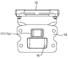
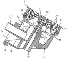
 次に、下側ケース12に設けられた連通筒部16及び筒状部材17について詳細に説明する。図6及び図7に示すように、下側ケース12の内部空間には、円筒状のジョイント部19が上方に向けて突設されている。そして、筒状部材17の一部分がジョイント部19に沿って設けられている。この筒状部材17は途中でL字状に屈曲されており、残りの部分が連通筒部16と並行に設けられている。図8にも示すように、筒状部材17は、連通筒部16の直上に設けられており、その端部はフランジ18から突出されている。 Next, the communication cylinder part 16 and the cylindrical member 17 provided in the lower case 12 will be described in detail. As shown in FIGS. 6 and 7, a cylindrical joint portion 19 protrudes upward in the internal space of the lower case 12. A part of the cylindrical member 17 is provided along the joint portion 19. The tubular member 17 is bent in an L shape in the middle, and the remaining portion is provided in parallel with the communication tubular portion 16. As shown also in FIG. 8, the cylindrical member 17 is provided immediately above the communicating cylinder portion 16, and an end portion thereof protrudes from the flange 18.
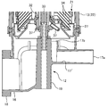
 図9に示すように、ジョイント部19の上端部は、固定フレーム55に嵌合されている。この固定フレーム55は、下側ケース12の嵌合部14に取り付けられる金属製の枠体である(図4を参照)。そして、筒状部材17は、ブローバイガスの導入入口側部分17aが、フランジ18よりも後方(図9における右側)に突設され、導入出口側部分17bがジョイント部19の近傍であって、固定フレーム55の直下に配置されている。 As shown in FIG. 9, the upper end portion of the joint portion 19 is fitted to the fixed frame 55. The fixed frame 55 is a metal frame attached to the fitting portion 14 of the lower case 12 (see FIG. 4). The cylindrical member 17 has a blow-by gas introduction inlet side portion 17a projecting behind the flange 18 (right side in FIG. 9) and an introduction outlet side portion 17b in the vicinity of the joint portion 19 and fixed. It is arranged immediately below the frame 55.
 ここで、導入出口側部分17bの開口幅は、固定フレーム55を構成する枠体の幅よりも十分に広く設けられている。なお、本実施形態では、導入出口側部分17bの開口面積と出口パイプ26(図2参照)の開口面積とを揃えており、ブローバイガスを円滑に流している。そして、筒状部材17から排出されたブローバイガスは、固定フレーム55を通過して上方に流れ込み、噴射孔39の軌跡よりも回転中心側からローター31の中空部分に流入する。 Here, the opening width of the introduction outlet side portion 17 b is sufficiently wider than the width of the frame constituting the fixed frame 55. In the present embodiment, the opening area of the introduction outlet side portion 17b and the opening area of the outlet pipe 26 (see FIG. 2) are aligned, and the blow-by gas flows smoothly. The blow-by gas discharged from the cylindrical member 17 flows upward through the fixed frame 55 and flows into the hollow portion of the rotor 31 from the rotation center side with respect to the locus of the injection holes 39.
 そして、筒状部材17(ガス導入部)の導入出口側部分17bに関し、その開口がノズル37の下側近傍に臨んでいれば、具体的には、図9に符号Xの点線で示すように、噴射孔39からスピンドル32の軸線に対して45度斜め下方に拡開された範囲内であって、噴射孔39の高さから噴射孔39の回転直径dの2/3だけ下方の範囲内に臨んでいれば、ブローバイガスを効率よくローター31の中空部分へと流入させることができる。これにより、噴射孔39から噴射されたオイルの巻き込みを抑制しつつ、筒状部材17から排出されたブローバイガスを、噴射孔39の軌跡よりも回転中心側から上側収容室42へ導入できる。 Then, regarding the introduction outlet side portion 17b of the cylindrical member 17 (gas introduction portion), if the opening faces the lower side of the nozzle 37, specifically, as indicated by the dotted line X in FIG. , Within a range that is obliquely expanded downward by 45 degrees with respect to the axis of the spindle 32 from the injection hole 39 and that is below the height of the injection hole 39 by 2/3 of the rotational diameter d of the injection hole 39. The blow-by gas can be efficiently flowed into the hollow portion of the rotor 31 as long as it faces. Thereby, the blow-by gas discharged from the cylindrical member 17 can be introduced into the upper storage chamber 42 from the rotation center side with respect to the locus of the injection hole 39 while suppressing the entrainment of the oil injected from the injection hole 39.
 そして、ノズル37(噴射孔39)から噴射されたオイルは、ブローバイガスから分離されたオイルと共に下側収容室41の底部に集められ、連通筒部16を通じてエンジン4に戻される。本実施形態では、ブローバイガスの流路が筒状部材17によって区画されているので、オイルの流れは、ブローバイガスの流れによる影響を受け難くなっている。 Then, the oil injected from the nozzle 37 (injection hole 39) is collected at the bottom of the lower housing chamber 41 together with the oil separated from the blow-by gas, and is returned to the engine 4 through the communication cylinder portion 16. In this embodiment, since the flow path of blow-by gas is partitioned by the cylindrical member 17, the flow of oil is hardly affected by the flow of blow-by gas.
 次に、図10を参照し、上記のように構成されたオイルセパレータ2におけるブローバイガスからのミスト状オイルの分離について説明する。 Next, the separation of the mist-like oil from the blow-by gas in the oil separator 2 configured as described above will be described with reference to FIG.
 エンジン4からオイル供給パイプ9を通じてジョイント部19に供給されたオイルは、符号F1の矢印で示すように、スピンドルシャフト33へ流入する。その後、オイルは、スピンドルシャフト33からノズル本体38に流入し、符号F2の矢印で示すように、噴射孔39から噴射される。各噴射孔39からオイルが噴射されると、ローター31及びスピンドル32はスピンドルシャフト33を中心に回転する。 The oil supplied from the engine 4 to the joint portion 19 through the oil supply pipe 9 flows into the spindle shaft 33 as indicated by the arrow F1. Thereafter, the oil flows from the spindle shaft 33 into the nozzle body 38 and is injected from the injection hole 39 as indicated by the arrow F2. When oil is injected from each injection hole 39, the rotor 31 and the spindle 32 rotate around the spindle shaft 33.
 噴射されたオイルは、区画部材27のテーパー部45に吹き付けられ、符号F3の矢印で示すように、テーパー部45の傾斜面45aに沿って外周側の斜め下方向とへ案内される。これにより、オイル飛沫のブローバイガスへの混入を抑制できる。その後、オイルは、符号F4の矢印で示すように、下側ケース12の内表面を下側収容室41の底部に向けて流下する。さらに、オイルは、符号F5の矢印で示すように、連通筒部16に流入され、エンジン4の側面からクランクケースへ戻される。 The injected oil is sprayed onto the tapered portion 45 of the partition member 27 and is guided in the obliquely downward direction on the outer peripheral side along the inclined surface 45a of the tapered portion 45, as indicated by the arrow F3. Thereby, mixing of the oil splash into the blow-by gas can be suppressed. Thereafter, the oil flows down the inner surface of the lower case 12 toward the bottom of the lower storage chamber 41 as indicated by an arrow F4. Further, the oil flows into the communication cylinder portion 16 and is returned from the side surface of the engine 4 to the crankcase as indicated by an arrow F5.
 一方、エンジン4からのブローバイガスは、符号F11の矢印で示すように、筒状部材17によって案内される。その後、符号F12の矢印で示すように、導入出口側部分17bから排出されたブローバイガスは、噴射孔39の移動軌跡の内側を通ってローター31の中空部分に流入する。筒状部材17が独立した流路を形成していることから、オイルの流れは、ブローバイガスの流れによる影響を受け難い。 On the other hand, blow-by gas from the engine 4 is guided by the tubular member 17 as indicated by an arrow F11. Thereafter, as indicated by the arrow F12, the blow-by gas discharged from the inlet / outlet side portion 17b flows into the hollow portion of the rotor 31 through the inside of the movement locus of the injection hole 39. Since the cylindrical member 17 forms an independent flow path, the oil flow is hardly affected by the blow-by gas flow.
 ローター31の中空部分に流入したブローバイガスは、ローター31の回転に伴って生じる遠心力により、符号F13の矢印で示すように、分離ディスク34同士の隙間をローター31の外周方向へ移動する。このように、遠心力によってブローバイガスがローター31の外周方向へ移動すると、ローター31における内周側の圧力が外周側の圧力よりも低くなる。この圧力差により、下側収容室41のブローバイガスがローター31の中空部分に流入し易くなるので、ブローバイガスの流入効率を高めることができる。 The blow-by gas that has flowed into the hollow portion of the rotor 31 moves through the gap between the separation disks 34 toward the outer periphery of the rotor 31 by the centrifugal force generated as the rotor 31 rotates, as indicated by the arrow F13. Thus, when blow-by gas moves in the outer circumferential direction of the rotor 31 by centrifugal force, the pressure on the inner circumferential side of the rotor 31 becomes lower than the pressure on the outer circumferential side. This pressure difference makes it easier for the blow-by gas in the lower housing chamber 41 to flow into the hollow portion of the rotor 31, so that the inflow efficiency of the blow-by gas can be increased.
 ブローバイガスが分離ディスク34に接触すると、このブローバイガスに含まれるミスト状オイルが分離ディスク34の表面に付着する。そして、付着したミスト状オイルに別のミスト状オイルが合体し、分離ディスク34の表面でオイルが凝集される。すなわち、オイルが二次分離される。前述したように、ブローバイガスは、下側収容室41でミスト状オイルが一次分離されている。このため、分離ディスク34での二次分離により、ミスト状オイルは高いレベルでブローバイガスから分離される。このように、上側収容室42は、ミスト状オイルが一次分離された後のブローバイガスについて、残存するミスト状オイルを二次分離する二次分離室に相当する。 When the blow-by gas comes into contact with the separation disk 34, mist-like oil contained in the blow-by gas adheres to the surface of the separation disk 34. Then, another mist-like oil is combined with the attached mist-like oil, and the oil is aggregated on the surface of the separation disk 34. That is, the oil is secondarily separated. As described above, the blow-by gas is primarily separated from the mist-like oil in the lower housing chamber 41. For this reason, the mist oil is separated from the blow-by gas at a high level by the secondary separation in the separation disk 34. Thus, the upper storage chamber 42 corresponds to a secondary separation chamber that secondary-separates the remaining mist-like oil with respect to the blow-by gas after the mist-like oil is primarily separated.
 また、スピンドル32とスピンドルシャフト33の間には隙間SPが形成されている。この隙間は、オイル案内路として機能し、ノズル37から噴射させるべく供給されたオイルで満たされる。ここで、オイルの供給圧力が十分に高いことから、隙間に充填されたオイルの一部は、隙間の上端を通ってスピンドル32の上端部からローター31の中空部分に放出される。そして、ローター31の中空部分に放出されたオイルはブローバイガスと同じく、ローター31の遠心力によって分離ディスク34同士の隙間をローター31の外周方向へ移動する。 Further, a gap SP is formed between the spindle 32 and the spindle shaft 33. This gap functions as an oil guide path and is filled with oil supplied to be ejected from the nozzle 37. Here, since the supply pressure of the oil is sufficiently high, a part of the oil filled in the gap is discharged from the upper end portion of the spindle 32 to the hollow portion of the rotor 31 through the upper end of the gap. The oil discharged into the hollow portion of the rotor 31 moves in the gap between the separation disks 34 in the outer circumferential direction of the rotor 31 by the centrifugal force of the rotor 31 as in the blow-by gas.
 分離ディスク34の表面で凝集されたオイルは、ローター31の中空部分に放出されたオイルと合体する。これにより、分離ディスク34の表面が洗浄され、分離ディスク34に対するメンテナンスを簡略化できる。分離ディスク34の表面で凝集されたオイルや合体されたオイルは、分離ディスク34の外周縁から放出され、本体カバー22の内表面に衝突した後、この内表面を流下する。さらに、オイルは、下側収容室41でノズル37から噴射されたオイルと合流し、エンジン4へと戻される。 The oil aggregated on the surface of the separation disk 34 is combined with the oil discharged into the hollow portion of the rotor 31. As a result, the surface of the separation disk 34 is cleaned, and maintenance for the separation disk 34 can be simplified. Oil agglomerated or coalesced on the surface of the separation disk 34 is discharged from the outer peripheral edge of the separation disk 34, collides with the inner surface of the main body cover 22, and then flows down the inner surface. Further, the oil merges with the oil injected from the nozzle 37 in the lower accommodation chamber 41 and is returned to the engine 4.
 ローター31を通過して、ミスト状オイルが分離されたブローバイガスは、上側収容室42における上側ケース13の内表面とローター31との隙間を、旋回しながら上昇する。ここで、分離されたオイルがブローバイガスの旋回流に乗って上昇することが考えられるが、本体カバー22の内表面に設けられた縦リブ24(図4参照)によって移動を阻まれて合体し、この縦リブ24に沿って流下する。また、本体カバー22の内表面に沿って外周側から内周側へとオイルが流れても、円筒リブ54によってオイルを滴状にして落下させることができる。 The blow-by gas from which the mist-like oil has been separated after passing through the rotor 31 rises while turning around the gap between the inner surface of the upper case 13 and the rotor 31 in the upper storage chamber 42. Here, it is conceivable that the separated oil rises on the swirling flow of blow-by gas. Then, it flows down along the vertical ribs 24. Even if the oil flows from the outer peripheral side to the inner peripheral side along the inner surface of the main body cover 22, the oil can be dropped in the form of droplets by the cylindrical rib 54.
 このようにして、ミスト状オイルが分離されたブローバイガスは、符号F14,F15の矢印で示すように、PCVバルブ28の上面側空間に導かれる。その後、符号F16の矢印で示すように、出口パイプ26を通ってブリーザーパイプ3へと導かれる。そして、本実施形態のオイルセパレータ2では、筒状部材17によってブローバイガス用の独立した流路が形成されているので、例えば図11に示すように前方へ傾斜しても、下側収容室41に溜まったオイルOLがブローバイガスの流れによって波打つことはない。これにより、オイルがローター31側へ浸入することを防止でき、ガスの浄化性能を高いレベルで維持できる。 In this way, the blowby gas from which the mist-like oil has been separated is guided to the space on the upper surface side of the PCV valve 28 as indicated by the arrows F14 and F15. Thereafter, as indicated by an arrow F <b> 16, the air is guided to the breather pipe 3 through the outlet pipe 26. And in the oil separator 2 of this embodiment, since the independent flow path for blow-by gas is formed by the cylindrical member 17, even if it inclines forward as shown, for example in FIG. The oil OL accumulated in the tank is not undulated by the flow of blow-by gas. Thereby, oil can be prevented from entering the rotor 31 side, and the gas purification performance can be maintained at a high level.
 また、本実施形態のオイルセパレータ2では、分離ディスク34を、外周側に向けて下り傾斜されたリング状の板材で構成しているので、分離ディスク34で分離されたオイルが下向きに流れることとなり、処理後ガスへのオイルの混入を抑制できる。加えて、図9等に示すように、筒状部材17(ガス流入部)における流入側部分が、連通筒部16(オイル排出部)と並行に設けられているので、装置の小型化が図れる。 Further, in the oil separator 2 of the present embodiment, the separation disk 34 is composed of a ring-shaped plate material that is inclined downward toward the outer peripheral side, so that the oil separated by the separation disk 34 flows downward. , It is possible to suppress oil from being mixed into the treated gas. In addition, as shown in FIG. 9 and the like, since the inflow side portion of the cylindrical member 17 (gas inflow portion) is provided in parallel with the communication cylinder portion 16 (oil discharge portion), the apparatus can be downsized. .
 以上の実施形態の説明は、本発明の理解を容易にするためのものであり、本発明を限定するものではない。本発明はその趣旨を逸脱することなく、変更、改良され得ると共に本発明にはその等価物が含まれる。例えば、次のように構成してもよい。 The above description of the embodiment is intended to facilitate understanding of the present invention and does not limit the present invention. The present invention can be changed and improved without departing from the gist thereof, and the present invention includes equivalents thereof. For example, you may comprise as follows.
 前述の実施形態では、固定フレーム55によってジョイント部19の上端部、及び、スピンドルシャフト33の下端部を支持する構成であった。この点に関し、例えば図12に示すように、固定フレーム55を省略してもよい。これは、筒状部材17(ガス流入部)における排出側部分が、ジョイント部19と一体に設けられていることから、ジョイント部19の剛性が向上しているためである。 In the above-described embodiment, the upper end portion of the joint portion 19 and the lower end portion of the spindle shaft 33 are supported by the fixed frame 55. In this regard, for example, as shown in FIG. 12, the fixed frame 55 may be omitted. This is because the rigidity of the joint portion 19 is improved because the discharge side portion of the cylindrical member 17 (gas inflow portion) is provided integrally with the joint portion 19.
 また、図13~15に示すように、筒状部材17´(ガス流入部)における導入入口側部分17aを、下側ケース12における連通筒部16(オイル排出部)とは異なる位置、具体的には下側ケース12の前面から前方に突設させてもよい。このように構成することで、ブローバイガスをホース等で案内する車種にも容易に適用できる。なお、導入入口側部分17aの突設位置は、下側ケース12の前面に限らず、左右何れかの側面であってもよい。 Further, as shown in FIGS. 13 to 15, the introduction inlet side portion 17a in the cylindrical member 17 ′ (gas inflow portion) is located at a position different from the communicating cylinder portion 16 (oil discharge portion) in the lower case 12, specifically May project forward from the front surface of the lower case 12. By comprising in this way, it can apply easily also to the vehicle type which guides blow-by gas with a hose etc. The protruding position of the introduction inlet side portion 17a is not limited to the front surface of the lower case 12, and may be either the left or right side surface.
1…閉鎖型クランクケース換気システム,2…オイルセパレータ,3…ブリーザーパイプ,4…エンジン,5…吸気側流路,6…エアフィルタ,7…ターボチャージャー,8…チャージクーラー,9…オイル供給パイプ,11…ハウジング,12…下側ケース,13…上側ケース,14…下側ケースの嵌合部,15…上側ケースの下端部,16…連通筒部,17,17´…筒状部材,17a…筒状部材の導入入口側部分,17b…筒状部材の導入出口側部分,18…フランジ,19…ジョイント部,21…ローターユニット,22…本体カバー,23…円盤状の上面カバー,24…縦リブ,25…ガス排出部,26…出口パイプ,27…区画部材,28…PCVバルブ,31…ローター,32…スピンドル,33…スピンドルシャフト,33a…オイル供給路,34…分離ディスク,35…上部ホルダ,36…下部ホルダ,36a…連結アーム,37…ノズル,38…ノズル本体,39…噴射孔,41…下側収容室,42…上側収容室,43…連通口,44…区画部材の外周部,45…区画部材のテーパー部,45a…テーパー部の傾斜面,46…区画部材の鍔部,47…PCVバルブのダイヤフラム,48…PCVバルブの上側スプリング,49…PCVバルブの下側スプリング,51…台座部,52…大気連通部,53…連通窓部,54…円筒リブ,55…固定フレーム,AL…スピンドルの軸線方向,NL…ノズル本体の軸線方向,SP…スピンドルとスピンドルシャフトの隙間,OL…下側収容室に溜まったオイル DESCRIPTION OF SYMBOLS 1 ... Closed-type crankcase ventilation system, 2 ... Oil separator, 3 ... Breather pipe, 4 ... Engine, 5 ... Intake side flow path, 6 ... Air filter, 7 ... Turbocharger, 8 ... Charge cooler, 9 ... Oil supply pipe , 11 ... Housing, 12 ... Lower case, 13 ... Upper case, 14 ... Lower case fitting part, 15 ... Lower end part of upper case, 16 ... Communication cylinder part, 17, 17 '... Cylindrical member, 17a ... inlet side portion of the cylindrical member, 17b ... inlet side portion of the cylindrical member, 18 ... flange, 19 ... joint portion, 21 ... rotor unit, 22 ... main body cover, 23 ... disc-shaped top cover, 24 ... Longitudinal rib, 25 ... gas discharge part, 26 ... exit pipe, 27 ... partition member, 28 ... PCV valve, 31 ... rotor, 32 ... spindle, 33 ... spindle shaft, 33 DESCRIPTION OF SYMBOLS Oil supply path 34 ... Separation disc 35 ... Upper holder 36 ... Lower holder 36a ... Connecting arm 37 ... Nozzle 38 ... Nozzle body 39 ... Injection hole 41 ... Lower storage chamber 42 ... Upper storage Chamber, 43 ... Communication port, 44 ... Peripheral part of partition member, 45 ... Tapered part of partition member, 45a ... Inclined surface of taper part, 46 ... Gutter part of partition member, 47 ... Diaphragm of PCV valve, 48 ... PCV valve Upper spring, 49 ... lower spring of the PCV valve, 51 ... pedestal, 52 ... atmospheric communication, 53 ... communication window, 54 ... cylindrical rib, 55 ... fixed frame, AL ... spindle axial direction, NL ... nozzle Main body axial direction, SP: Clearance between spindle and spindle shaft, OL: Oil accumulated in lower storage chamber

Claims (7)

  1.  処理対象ガスに含まれるミスト状オイルを分離するオイルセパレータであって、
     スピンドルと共に回転可能に設けられ、前記スピンドルの軸線方向に積層された複数枚の分離ディスクと、
     前記スピンドルにおける前記分離ディスクよりも下側の周面から突設され、噴射孔からオイルを噴射させることで軸線を中心に前記スピンドルを回転させるノズルと、
     前記処理対象ガスを導入するガス導入部、及び、オイルを排出させるオイル排出部が設けられた下側ケースと、
     前記下側ケースに上方から取り付けられ、前記スピンドル、前記分離ディスク、及び前記ノズルが収容される収容室を、前記下側ケースと共に区画する上側ケースと、
     前記収容室を、下側収容室と上側収容室とに区画し、かつ、前記下側収容室の前記処理対象ガスを前記上側収容室に案内する連通口を、前記ノズルと前記分離ディスクの間の高さにおける前記スピンドルの周囲に形成する区画部材とを有し、
     前記ガス導入部は、
      前記処理対象ガスの導入入口端部が、前記下側ケースの外に臨み、
      前記処理対象ガスの導入出口端部が、前記ノズルの下側近傍に臨む筒状部材によって構成されていることを特徴とするオイルセパレータ。
    An oil separator for separating mist oil contained in a gas to be treated,
    A plurality of separation discs provided rotatably with the spindle and stacked in the axial direction of the spindle;
    A nozzle that protrudes from a peripheral surface below the separation disk in the spindle, and rotates the spindle around an axis by injecting oil from an injection hole;
    A gas introduction part for introducing the gas to be treated, and a lower case provided with an oil discharge part for discharging oil;
    An upper case that is attached to the lower case from above and divides a storage chamber in which the spindle, the separation disk, and the nozzle are stored, together with the lower case;
    The storage chamber is divided into a lower storage chamber and an upper storage chamber, and a communication port for guiding the processing target gas in the lower storage chamber to the upper storage chamber is provided between the nozzle and the separation disk. A partition member formed around the spindle at a height of
    The gas introduction part is
    The inlet end portion of the processing target gas faces outside the lower case,
    An oil separator, wherein an inlet / outlet end portion of the gas to be treated is formed of a cylindrical member facing the lower side of the nozzle.
  2.  前記スピンドルは、スピンドルシャフトによって回転可能に支持され、
     前記下側ケースには、前記スピンドルシャフトの下端部が嵌合されるジョイント部が設けられ、
     前記ガス導入部の導入出口側部分は、前記ジョイント部に沿って設けられていることを特徴とする請求項1に記載のオイルセパレータ。
    The spindle is rotatably supported by a spindle shaft;
    The lower case is provided with a joint portion into which the lower end portion of the spindle shaft is fitted,
    The oil separator according to claim 1, wherein an introduction outlet side portion of the gas introduction part is provided along the joint part.
  3.  前記スピンドルシャフトは、前記スピンドルの動力となるオイルを供給する円筒状部材によって構成され、
     前記ジョイント部は、前記スピンドルシャフトに前記オイルを供給する筒状部材によって構成されていることを特徴とする請求項2に記載のオイルセパレータ。
    The spindle shaft is constituted by a cylindrical member that supplies oil to be the power of the spindle,
    The oil separator according to claim 2, wherein the joint portion is configured by a cylindrical member that supplies the oil to the spindle shaft.
  4.  前記処理対象ガスの導入出口端部は、前記噴射孔の高さから当該噴射孔の回転直径dだけ下方の高さ範囲内であって、1.5dの回転直径範囲内に臨んでいることを特徴とする請求項1~3の何れか1項に記載のオイルセパレータ。 The inlet / outlet end of the gas to be processed is within a height range below the injection hole height by the rotation diameter d of the injection hole and faces the rotation diameter range of 1.5d. The oil separator according to any one of claims 1 to 3, characterized in that:
  5.  前記区画部材は、外周側に向けて下り傾斜されたリング状の板材であって、下り傾斜面に前記噴射孔から噴射された前記オイルが吹き付けられることを特徴とする請求項1から4の何れか1項に記載のオイルセパレータ。 The said partition member is a ring-shaped board | plate material inclined downward toward the outer peripheral side, The said oil injected from the said injection hole is sprayed on a downward inclined surface, Any one of Claim 1 to 4 characterized by the above-mentioned. The oil separator according to claim 1.
  6.  前記ガス導入部の導入入口側部分は、前記オイル排出部と並行に設けられていることを特徴とする請求項1から5の何れか1項に記載のオイルセパレータ。 The oil separator according to any one of claims 1 to 5, wherein an inlet side portion of the gas introduction part is provided in parallel with the oil discharge part.
  7.  前記ガス導入部の導入入口側部分は、前記下側ケースにおける前記オイル排出部とは異なる位置から、前記下側ケースよりも外側に突設されていることを特徴とする請求項1から5の何れか1項に記載のオイルセパレータ。 The introduction inlet side portion of the gas introduction part protrudes outward from the lower case from a position different from the oil discharge part in the lower case. The oil separator according to any one of the above.
PCT/JP2014/054426 2014-02-25 2014-02-25 Oil separator WO2015128925A1 (en)

Priority Applications (4)

Application Number Priority Date Filing Date Title
EP14883775.0A EP3112032B1 (en) 2014-02-25 2014-02-25 Oil separator
US15/121,660 US20160375387A1 (en) 2014-02-25 2014-02-25 Oil separator
PCT/JP2014/054426 WO2015128925A1 (en) 2014-02-25 2014-02-25 Oil separator
JP2016504875A JP6255476B2 (en) 2014-02-25 2014-02-25 Oil separator

Applications Claiming Priority (1)

Application Number Priority Date Filing Date Title
PCT/JP2014/054426 WO2015128925A1 (en) 2014-02-25 2014-02-25 Oil separator

Publications (1)

Publication Number Publication Date
WO2015128925A1 true WO2015128925A1 (en) 2015-09-03

Family

ID=54008298

Family Applications (1)

Application Number Title Priority Date Filing Date
PCT/JP2014/054426 WO2015128925A1 (en) 2014-02-25 2014-02-25 Oil separator

Country Status (4)

Country Link
US (1) US20160375387A1 (en)
EP (1) EP3112032B1 (en)
JP (1) JP6255476B2 (en)
WO (1) WO2015128925A1 (en)

Cited By (2)

* Cited by examiner, † Cited by third party
Publication number Priority date Publication date Assignee Title
WO2017134055A1 (en) * 2016-02-01 2017-08-10 Reinz-Dichtungs-Gmbh Oil separator
US11097285B2 (en) * 2018-01-11 2021-08-24 Kuhn Performance Technologies, Llc Crankcase ventilation management devices, systems, and methods

Families Citing this family (3)

* Cited by examiner, † Cited by third party
Publication number Priority date Publication date Assignee Title
EP3441145A4 (en) * 2016-04-06 2019-12-11 Tokyo Roki Co., Ltd. Oil separator
DE202017100779U1 (en) * 2017-02-14 2018-05-15 Reinz-Dichtungs-Gmbh Oil separator with split drive chamber
EP3838376B1 (en) * 2019-12-16 2022-09-21 Alfdex AB Centrifugal separator and machine comprising a centrifugal separator

Citations (6)

* Cited by examiner, † Cited by third party
Publication number Priority date Publication date Assignee Title
WO1999051353A1 (en) * 1998-04-02 1999-10-14 Alfa Laval Ab Rotor for centrifugal separator
JP2005507310A (en) * 2001-11-01 2005-03-17 アルファ ラヴァル コーポレイト アクチボラゲット Device for purifying liquid and gas simultaneously
JP2005515065A (en) * 2002-01-25 2005-05-26 アルファ ラヴァル コーポレイト アクチボラゲット A device that purifies liquid and gas simultaneously
JP2008502473A (en) * 2004-06-16 2008-01-31 3ニーネ アクチボラゲット Centrifuge rotor unit
JP2009167812A (en) * 2008-01-10 2009-07-30 Toyota Boshoku Corp Centrifuging oil filter
JP2011528280A (en) * 2008-07-16 2011-11-17 アルファ ラヴァル コーポレイト アクチボラゲット centrifuge

Family Cites Families (16)

* Cited by examiner, † Cited by third party
Publication number Priority date Publication date Assignee Title
US6183407B1 (en) * 1998-04-02 2001-02-06 Alfa Laval Ab Centrifugal separator having axially-extending, angled separation discs
US6017300A (en) * 1998-08-19 2000-01-25 Fleetguard, Inc. High performance soot removing centrifuge with impulse turbine
SE515302C2 (en) * 1999-11-15 2001-07-09 Alfa Laval Ab A method and apparatus for purifying gas
SE517663C2 (en) * 2000-10-27 2002-07-02 Alfa Laval Corp Ab Centrifugal separator for purification of a gaseous fluid
DE10063903A1 (en) * 2000-12-21 2002-07-04 Mann & Hummel Filter Free jet centrifuge with integrated oil separator
SE0201982D0 (en) * 2002-06-24 2002-06-24 Alfa Laval Corp Ab Ways to clean crankcase gas and a gas purifier separator
SE523676C2 (en) * 2002-09-04 2004-05-11 Alfa Laval Corp Ab Gas purification apparatus
SE529609C2 (en) * 2006-02-13 2007-10-02 Alfa Laval Corp Ab centrifugal
US7338546B2 (en) * 2006-04-19 2008-03-04 Alfa Laval Corporate Ab Centrifugal separator for cleaning gas generated by an internal combustion engine and a method for operating the same
SE530223C2 (en) * 2006-05-15 2008-04-01 Alfa Laval Corp Ab centrifugal
DE202007009913U1 (en) * 2007-07-13 2008-11-20 Hengst Gmbh & Co.Kg Separator for separating oil mist from the crankcase ventilation gas of an internal combustion engine and internal combustion engine with a separator
US20110011795A1 (en) * 2009-07-15 2011-01-20 Hoff William D Fluid pressure driven centrifuge apparatus
DE102011076465B4 (en) * 2011-05-25 2021-04-29 Hengst Se Centrifugal separator for separating oil mist from the crankcase ventilation gas of an internal combustion engine
US9987579B2 (en) * 2013-03-28 2018-06-05 Tokyo Roki Co., Ltd. Oil separator
EP2944391A1 (en) * 2014-05-13 2015-11-18 Alfa Laval Corporate AB Centrifugal separator
EP3311923B1 (en) * 2015-06-19 2019-11-27 Tokyo Roki Co., Ltd. Oil separator

Patent Citations (6)

* Cited by examiner, † Cited by third party
Publication number Priority date Publication date Assignee Title
WO1999051353A1 (en) * 1998-04-02 1999-10-14 Alfa Laval Ab Rotor for centrifugal separator
JP2005507310A (en) * 2001-11-01 2005-03-17 アルファ ラヴァル コーポレイト アクチボラゲット Device for purifying liquid and gas simultaneously
JP2005515065A (en) * 2002-01-25 2005-05-26 アルファ ラヴァル コーポレイト アクチボラゲット A device that purifies liquid and gas simultaneously
JP2008502473A (en) * 2004-06-16 2008-01-31 3ニーネ アクチボラゲット Centrifuge rotor unit
JP2009167812A (en) * 2008-01-10 2009-07-30 Toyota Boshoku Corp Centrifuging oil filter
JP2011528280A (en) * 2008-07-16 2011-11-17 アルファ ラヴァル コーポレイト アクチボラゲット centrifuge

Non-Patent Citations (1)

* Cited by examiner, † Cited by third party
Title
See also references of EP3112032A4 *

Cited By (3)

* Cited by examiner, † Cited by third party
Publication number Priority date Publication date Assignee Title
WO2017134055A1 (en) * 2016-02-01 2017-08-10 Reinz-Dichtungs-Gmbh Oil separator
US11098622B2 (en) 2016-02-01 2021-08-24 3Nine Ab Oil separator
US11097285B2 (en) * 2018-01-11 2021-08-24 Kuhn Performance Technologies, Llc Crankcase ventilation management devices, systems, and methods

Also Published As

Publication number Publication date
EP3112032A4 (en) 2018-01-17
EP3112032A1 (en) 2017-01-04
JP6255476B2 (en) 2017-12-27
US20160375387A1 (en) 2016-12-29
JPWO2015128925A1 (en) 2017-03-30
EP3112032B1 (en) 2020-05-27

Similar Documents

Publication Publication Date Title
JP6069488B2 (en) Oil separator
JP6268302B2 (en) Oil separator
JP6286530B2 (en) Oil separator
JP6336037B2 (en) Oil separator
JP6255476B2 (en) Oil separator
WO2016046944A1 (en) Separation disk for oil separator, rotor for oil separator, and oil separator
JP6511522B2 (en) Oil separator
WO2014155614A1 (en) Oil separator
JP6647391B2 (en) Oil separator
JP6934471B2 (en) Oil separator
WO2016139716A1 (en) Separation disk and oil separator
JP6322715B2 (en) Method for separating mist oil and oil separator
JP6336038B2 (en) Oil separator
WO2016035204A1 (en) Oil separator
JP6726739B2 (en) Separated disc stack

Legal Events

Date Code Title Description
121 Ep: the epo has been informed by wipo that ep was designated in this application

Ref document number: 14883775

Country of ref document: EP

Kind code of ref document: A1

ENP Entry into the national phase

Ref document number: 2016504875

Country of ref document: JP

Kind code of ref document: A

NENP Non-entry into the national phase

Ref country code: DE

WWE Wipo information: entry into national phase

Ref document number: 15121660

Country of ref document: US

REEP Request for entry into the european phase

Ref document number: 2014883775

Country of ref document: EP

WWE Wipo information: entry into national phase

Ref document number: 2014883775

Country of ref document: EP