WO2015125573A1 - 人工歯 - Google Patents
人工歯 Download PDFInfo
- Publication number
- WO2015125573A1 WO2015125573A1 PCT/JP2015/052311 JP2015052311W WO2015125573A1 WO 2015125573 A1 WO2015125573 A1 WO 2015125573A1 JP 2015052311 W JP2015052311 W JP 2015052311W WO 2015125573 A1 WO2015125573 A1 WO 2015125573A1
- Authority
- WO
- WIPO (PCT)
- Prior art keywords
- artificial tooth
- denture
- tooth
- recess
- artificial
- Prior art date
Links
Images


Classifications
-
- A—HUMAN NECESSITIES
- A61—MEDICAL OR VETERINARY SCIENCE; HYGIENE
- A61C—DENTISTRY; APPARATUS OR METHODS FOR ORAL OR DENTAL HYGIENE
- A61C13/00—Dental prostheses; Making same
- A61C13/10—Fastening of artificial teeth to denture palates or the like
- A61C13/1003—Fastening of artificial teeth to denture palates or the like by embedding in base material
- A61C13/1006—Fastening of artificial teeth to denture palates or the like by embedding in base material characterised by a tooth shape which improves retention
-
- A—HUMAN NECESSITIES
- A61—MEDICAL OR VETERINARY SCIENCE; HYGIENE
- A61C—DENTISTRY; APPARATUS OR METHODS FOR ORAL OR DENTAL HYGIENE
- A61C13/00—Dental prostheses; Making same
- A61C13/0003—Making bridge-work, inlays, implants or the like
- A61C13/0006—Production methods
-
- A—HUMAN NECESSITIES
- A61—MEDICAL OR VETERINARY SCIENCE; HYGIENE
- A61C—DENTISTRY; APPARATUS OR METHODS FOR ORAL OR DENTAL HYGIENE
- A61C13/00—Dental prostheses; Making same
- A61C13/08—Artificial teeth; Making same
-
- A—HUMAN NECESSITIES
- A61—MEDICAL OR VETERINARY SCIENCE; HYGIENE
- A61C—DENTISTRY; APPARATUS OR METHODS FOR ORAL OR DENTAL HYGIENE
- A61C13/00—Dental prostheses; Making same
- A61C13/10—Fastening of artificial teeth to denture palates or the like
- A61C13/1003—Fastening of artificial teeth to denture palates or the like by embedding in base material
- A61C13/1013—Arch forms
- A61C13/1016—Methods or apparatus for mounting, holding or positioning a set of teeth
Definitions
- the present invention relates to an artificial tooth.
- One of the well-known methods for producing a denture is a lost wax method. This can be obtained through a process as follows to obtain a denture.
- an impression material is first used to take a shape of the shape in the patient's mouth (so-called impression taking).
- Gypsum is poured and hardened to make a plaster model.
- the height of the upper and lower jaw dentures is secured on the plaster model using wax, and artificial teeth are embedded in the wax to form wax dentures (so-called artificial tooth arrangement).
- the wax denture is buried in gypsum and hardened, and a part where the wax flows out is formed, and then the wax is melted and poured out using hot water or the like.
- the denture can be obtained by cracking and removing the plaster.
- the lost wax method has many steps and takes time to complete, and the skill of a dental technician is required for its production.
- Patent Documents 1 and 2 disclose a technique for producing a dental prosthesis such as a plate denture using CAD / CAM. That is, it is possible to obtain a dental prosthesis by using CAD / CAM to handle from the design to manufacture of the dental prosthesis as data, and finally carving it with an NC machine tool based on the data. According to this, there are few processes compared with the lost wax method, and it is possible to manufacture a dental prosthesis in a shorter period of time than before.
- the denture base is made by cutting a denture base with a hard resin material compared to wax, and an artificial tooth previously formed on the hard denture base is fitted. It was necessary to insert artificial teeth such as ceramics and resin into the recesses for insertion, and to fix them with an adhesive. Then, since it is necessary to form the hollow which fits an artificial tooth larger than an artificial tooth, especially in the shape where a cross section is a circle
- an object of the present invention is to provide an artificial tooth that can be easily and accurately attached to a denture base when arranging the artificial teeth on a denture base designed and formed by CAD / CAM.
- the present invention is an artificial tooth (21) having a shape corresponding to a denture base designed and cut out on CAD based on three-dimensional data, and the tooth axis is centered on a portion to be in contact with the denture base Means (21a to 21h) are provided for restricting the rotation of the tooth, and the means for restricting is an artificial tooth that has a shape that does not engage the denture base in the tooth axis direction.
- the “tooth axis” means the long axis of the artificial tooth.
- the means for regulating the artificial teeth (21a to 21h) may include at least one of a protrusion and a depression.
- an artificial tooth attached to a denture base designed and formed by CAD / CAM can be easily and accurately attached to the denture base while preventing rotation.
- FIG. 3 is a diagram illustrating an appearance of an artificial tooth 21.
- FIG. 4A is a diagram illustrating one scene where the artificial tooth 21 is attached to the denture base 11
- FIG. 4B is a diagram illustrating one scene where the artificial tooth 21 is attached to the denture base 11.
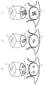
- 5A is a diagram showing the means 13a and 21a for restricting rotation
- FIG. 5B is a diagram showing the means 13b and 21b for restricting rotation
- FIG. 5C is a means 13c and 21c for restricting rotation.
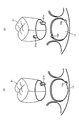
- FIG. FIG. 6A is a view showing the means 13d and 21d for restricting rotation
- FIG. 6B is a view showing the means 13e and 21e for restricting rotation.
- 7A is a view showing the means 13f and 21f for restricting rotation
- FIG. 7B is a view showing the means 13g and 21g for restricting rotation
- FIG. 7C is a means 13h and 21h for restricting rotation.
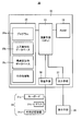
- FIG. 2 is a block diagram conceptually showing a design apparatus 30.
- FIG. It is a figure showing the flow of manufacturing method S1 of a denture. It is a figure showing the flow of process S20 of the design of a denture. It is a figure showing the flow of process S30 of preparation of a base denture.
- FIG. 1 is a diagram illustrating one embodiment, and is a diagram illustrating an appearance of a plate denture 10 including artificial teeth 21.
- a plate denture 10 is placed on the lower jaw side and / or the upper jaw side in the oral cavity of the patient to artificially supplement the missing natural tooth.
- the denture 10 has a denture base 11 and a plurality of artificial teeth 21.
- FIG. 2 shows the external appearance of the denture base 11
- FIG. 3 shows an artificial tooth 21 according to one example.
- an explanation will be given by taking, as an example, a base denture that supplements the entire jaw side as the base denture 10, but it may be a partial base denture that compensates for the loss of some natural teeth.
- the denture base 11 is a member having a function of holding the artificial tooth 21 in a predetermined position and stably mounting the denture itself on the oral mucosa.
- the ridge-like raised ridge portion 12 is provided as a portion where the artificial teeth 21 are arranged, and one end of the artificial tooth 21 is inserted into the top of the ridge portion 12, so that the artificial tooth 21 is provided.
- a recess 13 is provided in which is fixed.
- the artificial tooth 21 is an artificial tooth produced so as to have the function of the natural tooth instead of the missing natural tooth.
- One end of the artificial tooth 21 is inserted into the concave portion 13 of the denture base 11 and fixed by an adhesive.
- the plurality of artificial teeth 21 are arranged like an arch like an arch, and can function like a natural tooth.
- a known material used for artificial teeth can be applied to the artificial teeth 21.
- This can include, for example, ceramics, resins, hard resins, and metals.
- a known material can be used as a material for adhering the artificial tooth 21 to the denture base 11.
- a known polymer such as an immediate polymerization resin, a gingival color resin, a denture base resin, and an epoxy adhesive can be used.
- An industrial adhesive or a combination of at least two of these may be used.
- FIG. 4A is a perspective view schematically showing a state immediately before one artificial tooth 21 is attached to the recess 13 of the denture base 11, and
- FIG. 4B is a schematic view showing the attached state.
- one end surface of the artificial tooth 21 is positioned so as to face the bottom surface of the concave portion 13 of the denture base 11, and this is the direction indicated by the arrow IVa (the artificial tooth 21).
- the end surface of the artificial tooth 21 and the bottom surface of the recess 13 are brought together with each other in the insertion direction, for example, the tooth axis direction (direction along the tooth axis).
- the artificial tooth 21 is attached so as to protrude from the denture base 11 as shown in FIG.
- the adhesive is disposed and fixed between the end surface of the artificial tooth 21 and the bottom surface of the recess 13.
- the outer peripheral shape of the concave portion 13 is substantially the same as or slightly larger than the outer peripheral shape of the artificial tooth 21 at the inserted portion in the posture in which the end portion of the artificial tooth 21 is inserted inside the concave portion 13. preferable.
- the artificial tooth 21 is positioned in the direction along the bottom surface of the recess 13 with the posture in which the artificial tooth 21 is attached to the recess 13.
- the recess 13 and the portion of the artificial tooth 21 that is inserted into the recess 13 are not engaged with each other in the insertion direction (for example, the direction along the tooth axis (the tooth axis direction)) (for example, the shapes that do not catch each other). ) Is preferred.
- the denture base 11 is made of a hard material such as a hard resin, metal, or ceramic sintered body as described above, and therefore it is not suitable to provide an undercut, for example, to engage by so-called forced insertion. It depends.
- the artificial tooth 21 whose center (axis) is the direction along the protruding direction of the artificial tooth 21 (tooth axis direction of the artificial tooth 21). It is also necessary to regulate the rotation of Without this restriction, it cannot be said that the direction of rotation is strongly constrained, and there is a risk of rotation during attachment. Therefore, means for restricting the rotation of the artificial tooth 21 is provided in the concave portion 13 of the artificial tooth 21 and the denture base 11.
- the specific form of the means for restricting rotation is not particularly limited, for example, the artificial tooth 21 is provided with a protrusion or a hole, and the concave portion 13 of the denture base 11 is provided with a corresponding recess or protrusion. . Specific examples are shown in FIGS.
- FIG. 5A two columnar projections 21a are arranged on the surface of the artificial tooth 21 that faces the bottom surface of the recess 13, and the bottom surface of the recess 13 is provided with a recess 13a in a shape and position corresponding thereto.
- FIG. 5B one prismatic projection 21b is disposed on the surface of the artificial tooth 21 that faces the bottom surface of the recess 13, and the bottom surface of the recess 13 is provided with a recess 13b in the shape and position corresponding to this. This is an example.
- FIG. 5B two prismatic projection 21b is disposed on the surface of the artificial tooth 21 that faces the bottom surface of the recess 13, and the bottom surface of the recess 13 is provided with a recess 13b in the shape and position corresponding to this. This is an example.
- FIG. 5B two prismatic projection 21b is disposed on the surface of the artificial tooth 21 that faces the bottom surface of the recess 13, and the bottom surface of the recess 13 is provided with a recess
- one cross-shaped protrusion 21c is disposed on the surface of the artificial tooth 21 that faces the bottom surface of the recess 13, and the bottom surface of the recess 13 is provided with a recess 13c in a corresponding shape and position.
- the rotation can be restricted by inserting the protrusions 21a, 21b, and 21c corresponding to the recesses 13a, 13b, and 13c.
- the artificial tooth 21 is provided with a protrusion and a recess corresponding to the protrusion 13 is provided on the bottom surface of the recess 13. May be provided.
- one prismatic protrusion 21d is disposed on the surface of the artificial tooth 21 that faces the side surface of the recess 13, and the recess 13d is provided on the side surface of the recess 13 in the shape and position corresponding thereto. This is an example.
- FIG. 6B two semi-cylindrical protrusions 21 e on the surface of the artificial tooth 21 facing the side surface of the recess 13 are arranged, and the side surface of the recess 13 is recessed in a shape and position corresponding thereto.
- 13e is provided.
- a protrusion is provided on the side surface of the artificial tooth 21 and a corresponding recess is provided on the side surface of the recess 13.
- the recess is provided on the artificial tooth 21 side, and this corresponds to the side surface of the recess 13. Protrusions may be provided.
- two protuberances 21f are provided on the surface of the artificial tooth 21 that faces the side surface of the recess 13 with a predetermined interval, and the side surface of the recess 13 has a shape and position corresponding to this.
- a protrusion 21g is provided on the surface of the artificial tooth 21 that faces the bottom surface of the recess 13, and the recess 13f is formed on the side surface of the recess 13 in the same manner as described above. Is provided, and a recess 13g is provided in a shape and position corresponding to the protrusion 21g.
- two concave portions 21h are provided on the surface of the artificial tooth 21 that faces the side surface of the concave portion 13 with a predetermined interval, and the side surface of the concave portion 13 has a shape and a position corresponding thereto.
- a protrusion 13h is provided.
- the protrusion and the recess have a shape (for example, a shape that does not catch each other) that does not engage in the direction in which the protrusion is inserted into the recess (for example, the tooth axis direction). Therefore, the insertion can be performed without elastically or plastically deforming the protrusion and the depression.
- FIG. 8 is a block diagram conceptually showing a configuration included in the denture design device 30 according to one embodiment.
- the floor denture design device 30 (hereinafter sometimes referred to as “design device 30”) includes an input unit 31, an arithmetic unit 32, and a display unit 38.
- the arithmetic device 32 includes an arithmetic means 33, a RAM 34, a storage means 35, a receiving means 36, and an output means 37.
- the input means 31 includes a keyboard 31a, a mouse 31b, and an external storage device 31c that functions as one of storage media.
- the computing means 33 is constituted by a so-called CPU (central operator), and is a means that can be connected to and controlled by the above-described components. Also, the calculation means 33 executes various programs 35a stored in the storage means 35 or the like functioning as a storage medium, and performs calculation as means for generating various data and selecting data based on this program 35a. It is.
- the RAM 34 is a structural member that functions as a work area for the computing means 33 and a temporary data storage means.
- the RAM 34 can be configured by SRAM, DRAM, flash memory, or the like, and is similar to a known RAM.
- the storage means 35 is a member that functions as a storage medium for storing programs and data that are the basis for various calculations.
- the storage unit 35 may be capable of storing various intermediate and final results obtained by executing the program. More specifically, the storage unit 35 stores (saves) a program 35a, an artificial tooth shape database 35b, and a denture base shape database 35c. Other information may also be stored.
- the program 35a is a program necessary for operating the design apparatus 30, and is not particularly limited.
- the artificial tooth shape database 35b is a database that stores information such as shapes related to artificial teeth.
- the type of artificial tooth shape stored in the database is not particularly limited, but as a set of data, the upper and lower dental arches are bitten together with a plurality of artificial teeth included in the dental arch. The aspect accommodated may be sufficient.
- the data may be configured to be handled by several divided units including several artificial teeth in addition to each artificial tooth. Such a set of artificial teeth is preferably prepared with a plurality of variations for matching with patient characteristics such as “sex” and “physique”.
- the artificial tooth shape database 35b also includes a form of means for restricting the rotation described above.
- the denture base shape database 35c is a database in which information such as the shape related to the denture base is stored.
- the mode of data related to the denture base stored in the database is not particularly limited. For example, the positional relationship with the artificial tooth data in which “only the upper half including the part to which the artificial tooth is attached” is engaged (for example, for bonding) Data having a space of 0.1 mm to 0.5 mm or the like) may be stored. Regarding the variations, it is preferable that there are 3 to 4 types of data in combination with the size of the artificial tooth.
- the denture base shape database 35c includes a form of means for restricting rotation.
- the receiving means 36 is a structural member having a function for appropriately taking in information from the outside into the arithmetic device 32, and is connected to the input means 31. This includes so-called input ports, input connectors, and the like.
- the output means 37 is a structural member having a function of appropriately outputting information to be output to the outside among the obtained results, and a display means 38 such as a monitor and various devices are connected thereto. This includes so-called output ports, output connectors, and the like.
- the input device 31 includes, for example, a keyboard 31a, a mouse 31b, an external storage device 31c, and the like.
- the external storage device 31c is a known externally connectable storage unit and also functions as a storage medium.
- various necessary programs and data can be stored.
- the same program and data as the above-mentioned storage means 35 may be stored here.
- a known device can be used as the external storage device 31c. Examples thereof include CD-ROM and CD-ROM drive, DVD and DVD drive, hard disk, various memories and the like.
- information may be provided to the arithmetic device 32 via the receiving unit 36 by a network or communication.
- information may be transmitted to an external device (for example, NC machine tool) via the output unit 37 by a network or communication.
- the denture base can be directly cut out, and a denture base can be produced without going through a complicated process such as the lost wax method.
- manufacturing method S1 (which may be referred to as “manufacturing method S1”) for manufacturing the plate denture 10 using the design device 30 will be described.
- manufacturing method S1 an example using the design apparatus 30 will be described for the sake of clarity.
- the manufacturing method is not limited to this, and any other apparatus can be used as long as a method including the following points is possible. You can also.
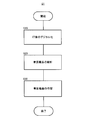
- FIG. 9 shows the flow of the manufacturing method S1.
- the manufacturing method S1 includes an impression digitization step S10, a floor denture design step S20, and a floor denture production step S30. Each process will be described below.
- Step S10 is a step of obtaining shape data and occlusal CAD data from the obtained impression.
- the impression itself is obtained by a known method, and information on the mucosal surface of the patient such as a plaster model can be obtained therefrom.
- a method for obtaining CAD data can be performed by using a known apparatus, such as a three-dimensional optical scanner.
- occlusion-related data can be obtained by three-dimensional measurement by combining the impression body of the upper jaw and the impression body of the lower jaw in the same manner as the patient's occlusion state.
- step S20 the shape of the bed denture 10 is finally determined on the data based on the information on the mucosal surface based on the patient obtained in step S10 and the database stored in the design apparatus 30. Further, in step S20, the artificial tooth data is deleted from the denture data that has been arranged, and machining data for denture base cutting is output to step S30 (machine tool) for producing a denture.
- step S20 Each calculation performed in step S20 in this embodiment is performed by the design apparatus 30. In other words, the calculation is performed by the calculation means 33 according to the program 35a stored in the storage device 35 provided in the design apparatus S30.
- FIG. 10 shows the flow of step S20. As can be seen, the step S20 includes an impression data acquisition step S21, a data call and arrangement position adjustment step S22, and an artificial tooth / denture base data output step S23.
- Step S21 is a step of acquiring information about the impression converted into data in step S10 and taking it into the design apparatus 30.
- the fetch is stored in the storage device 35 via the receiving means 36 of the design device 30.
- Step S22 is a step of calling information from the database and arranging artificial teeth on the design device 30. That is, based on the information acquired so far, artificial tooth data corresponding to the dental arch is called from the database stored in the storage means 35 of the design apparatus 30. Then, after arranging this at an approximate position on the jaw crest, the position is finely adjusted.
- Step S23 is a step of individually extracting the shape data of the artificial teeth and the shape data of the denture base from the shape determined in step S22 and outputting them as command data to the machine tool used in step S30. This output can be performed via the output means 37 of the design apparatus 30.
- Step S30 is a step of receiving the denture machining data output from step S20 and cutting out the shape with a machine tool, and combining them to finish the denture 10 in a denture.
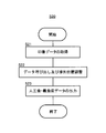
- FIG. 11 shows the flow of step S30.
- the step S30 includes a cutting step S31, an artificial tooth attachment step S32 on the denture base, and a final polishing step S33.
- Step S31 is a step in which the machine tool cuts the denture base by cutting based on the command data output to the machine tool output in step S23.
- a well-known thing can be used for a machine tool, It is not specifically limited, A well-known NC machine tool can be used.
- the denture base material used here is made of a hard material such as a hard resin, metal, or ceramic, so that cutting can be performed with good accuracy.
- Step S32 is a step of attaching an artificial tooth to the denture base obtained in step S31.
- the one end surface of the artificial tooth 21 is fixed so as to overlap the bottom surface of the concave portion 13 of the denture base 11.
- the denture and the denture base are provided with means for restricting rotation (for example, FIGS. 5 (a) to 5 (c))
- the rotation is also regulated and appropriate artificial teeth can be attached.
- both the artificial tooth and the denture base can be inserted without being deformed, it can be easily attached without being forcedly inserted.
- an adhesive is supplied and fixed between the end face of the artificial tooth 21 and the bottom face of the recess 13 which are arranged facing each other.
- step S33 the denture denture obtained in step S32 is subjected to finish polishing, and finally the denture 10 is obtained.
- the denture base 11 is formed of a hard material such as a hard resin, metal, or ceramic sintered body. Therefore, it is not suitable to provide an undercut, for example, so as to force engagement. Therefore, when the artificial tooth is attached to the denture base, there is a possibility that the rotation shown in FIG. 4 (b) may be a problem. In the present embodiment, since the means for restricting the rotation is provided, this can be solved.
Abstract
Description
次に、石膏模型の上にワックスを用いて上下顎義歯の高さを確保し、ワックスに人工歯を埋め込み、蝋義歯とする(いわゆる人工歯排列。)。その後この蝋義歯を石膏などに埋めて固めるとともにワックスが流出する部位を形成したうえで湯等を用いてワックスを溶融して流し去る。これにより排列された人工歯のみが残り、ワックスが存在していた部分に空洞が形成されるのでここにレジン等を流入(填入)させて硬化する。そして石膏を割って取り去ることにより有床義歯を得ることができる。
これによれば、ロストワックス法に比べて工程が少なく、歯科補綴物をこれまでより短期間で製作することが可能である。
ここで「歯軸」とは人工歯の長軸を意味する。
本形態では有床義歯10として一方の顎側全体を補う有床義歯を例に説明するが、一部の天然歯の欠損を補う部分的な有床義歯であってもよい。
また、義歯床11に人工歯21を接着する材料としては、公知の材料を用いることができるが、これには例えば即時重合レジン、歯肉色レジン、義歯床用レジン、エポキシ接着剤等の公知の工業用接着剤、又はこれらの少なくとも2つの組み合わせ等が挙げられる。
また、凹部13と、人工歯21のうち凹部13に挿入される部位とは、挿入の方向(例えば歯軸に沿った方向(歯軸方向))では係合しない形状(例えば互いに引っ掛かりがない形状)とされていることが好ましい。これにより当該挿入に際して互いに弾性変形、又は塑性変形を要しない関係となる。これは上記のように義歯床11が硬質のレジン、金属、セラミック焼結体等の硬質の材料で形成されているので、例えばアンダーカットを設けていわゆる無理入れにより係合させることは適していないことによる。
そこで、人工歯21及び義歯床11の凹部13には、人工歯21の回転を規制する手段が設けられている。回転を規制する手段の具体的な形態は特に限定されることはないが、例えば人工歯21に突起又は孔が設けられ、義歯床11の凹部13にはこれに対応する窪み又は突起が設けられる。図5~図7に具体例を表した。
図5(b)は、人工歯21のうち凹部13の底面に対向する面に1つの角柱状の突起21bが配置され、凹部13の底面にはこれに対応する形状及び位置に窪み13bが設けられている例である。
図5(c)は、人工歯21のうち凹部13の底面に対向する面に1つの十字状の突起21cが配置され、凹部13の底面にはこれに対応する形状及び位置に窪み13cが設けられている例である。
人工歯21を凹部13に挿入して人工歯21を配置するに際し、窪み13a、13b、13cに対応する突起21a、21b、21cが挿入されることにより、回転も規制することができる。
ここでは人工歯21に突起、凹部13の底面にこれに対応する窪みが設けられた例を表したが、これとは逆に人工歯21側に窪み、凹部13の底面にこれに対応する突起が設けられてもよい。
定されることはない。
このような人工歯の組は、例えば「性別」、「体格」等、患者の特徴に合わせるための複数のバリエーションを有したものが準備されていることが好ましい。
また、当該人工歯形状データベース35bには、上記説明した回転を規制する手段の形態も含まれている。
バリエーションについても人工歯の大きさに合わせた組み合わせで3~4種類の大きさのデータがあることが好ましい。
当該義歯床形状データベース35cには、回転を規制する手段の形態も含まれている。
外部記憶装置31cは、公知の外部接続可能な記憶手段であり、記憶媒体としても機能する。ここには特に限定されることなく、必要とされる各種プログラム、データを記憶させておくことができる。例えば上記した記憶手段35と同様のプログラム、データがここに記憶されていても良い。また、演算装置32によるデータ生成の際の基礎となる印象データや咬合関係のデータ等を外部記憶装置31cに記憶しておいてもよい。
外部記憶装置31cとしては、公知の装置を用いることができる。これには例えばCD-ROM及びCD-ROMドライブ、DVD及びDVDドライブ、ハードディスク、各種メモリ等を挙げることができる。
一方、咬合関係のデータは、上顎の印象体と下顎の印象体とを患者の咬合状態と同様に組み合わせて3次元計測することにより得ることができる。
図10に工程S20の流れを示した。ここからわかるように、工程S20は、印象データの取得の工程S21、データ呼び出し及び排列位置調整の工程S22、人工歯・義歯床データの出力の工程S23を含む。
図11には工程S30の流れを示した。図11からわかるように、工程S30は、切削加工の工程S31、義歯床への人工歯の取り付けの工程S32、及び仕上げ研磨の工程S33を備えている。
そして対向して配置された、人工歯21の端面と凹部13の底面との間に接着剤が塗布等により供給され、固定される。
11 義歯床
12 堤
13 凹部
21 人工歯
Claims (2)
- 3次元データを元にCAD上で設計され削り出された義歯床に対応する形状を有する人工歯であって、
前記義歯床に接触すべき部位には、歯軸を中心に回転することを規制する手段が設けられており、
前記規制する手段は、歯軸方向において前記義歯床に係合しない形状とされている人工歯。 - 前記規制する手段は、突起及び窪みの少なくとも1つを含む請求項1に記載の人工歯。
Priority Applications (5)
| Application Number | Priority Date | Filing Date | Title |
|---|---|---|---|
| EP15752345.7A EP3108851A4 (en) | 2014-02-18 | 2015-01-28 | Artificial tooth |
| CN201580007062.8A CN105960218B (zh) | 2014-02-18 | 2015-01-28 | 人工齿 |
| US15/119,248 US20170007381A1 (en) | 2014-02-18 | 2015-01-28 | Artificial tooth |
| KR1020167015329A KR20160123285A (ko) | 2014-02-18 | 2015-01-28 | 인공 치아 |
| JP2016504014A JP6322698B2 (ja) | 2014-02-18 | 2015-01-28 | 人工歯 |
Applications Claiming Priority (2)
| Application Number | Priority Date | Filing Date | Title |
|---|---|---|---|
| JP2014-028287 | 2014-02-18 | ||
| JP2014028287 | 2014-02-18 |
Publications (1)
| Publication Number | Publication Date |
|---|---|
| WO2015125573A1 true WO2015125573A1 (ja) | 2015-08-27 |
Family
ID=53878086
Family Applications (1)
| Application Number | Title | Priority Date | Filing Date |
|---|---|---|---|
| PCT/JP2015/052311 WO2015125573A1 (ja) | 2014-02-18 | 2015-01-28 | 人工歯 |
Country Status (6)
| Country | Link |
|---|---|
| US (1) | US20170007381A1 (ja) |
| EP (1) | EP3108851A4 (ja) |
| JP (1) | JP6322698B2 (ja) |
| KR (1) | KR20160123285A (ja) |
| CN (1) | CN105960218B (ja) |
| WO (1) | WO2015125573A1 (ja) |
Cited By (4)
| Publication number | Priority date | Publication date | Assignee | Title |
|---|---|---|---|---|
| EP3097887A1 (en) | 2015-07-27 | 2016-11-30 | Nicola Zucchini | Artificial pre-mounted teeth in a fixed and repeatable position for making a dental prosthesis and method for manufacturing such prostheses |
| EP3235469A1 (en) * | 2016-04-24 | 2017-10-25 | Johannes Petrus Michael Grobbee | A denture |
| JP2020010950A (ja) * | 2018-07-20 | 2020-01-23 | Dgshape株式会社 | 義歯床の製造方法および切削装置ならびに切削材料 |
| EP3973916A1 (en) | 2020-09-25 | 2022-03-30 | Kabushiki Kaisha Shofu | Method for producing denture with high accuracy of fitting of artificial tooth to socket |
Families Citing this family (8)
| Publication number | Priority date | Publication date | Assignee | Title |
|---|---|---|---|---|
| KR101857951B1 (ko) * | 2017-05-04 | 2018-05-16 | 주식회사 디오 | 틀니 제조방법 및 제조시스템 |
| KR101867040B1 (ko) * | 2017-05-04 | 2018-06-14 | 주식회사 디오 | 조립식 틀니장치 |
| US10952828B2 (en) * | 2017-10-05 | 2021-03-23 | Gc Corporation | Method for designing denture, method for producing denture and positioning means |
| CN108888372B (zh) * | 2018-04-25 | 2021-08-10 | 四川大学 | 一种基于智能推荐的虚拟活动义齿设计方法及系统 |
| CA185510S (en) * | 2018-07-05 | 2020-05-06 | Tokuyama Dental Corp | Denture arrangement device |
| US11660173B2 (en) * | 2019-02-15 | 2023-05-30 | Dentsply Sirona Inc. | Denture base and dental prosthesis |
| US20210298881A1 (en) * | 2020-03-26 | 2021-09-30 | Exocad Gmbh | Removable partial denture |
| CN113208758B (zh) * | 2021-05-17 | 2022-03-22 | 深圳市一诺牙科技术有限公司 | 采用铜片活性炭组合的高弹性隐形活动义齿 |
Citations (2)
| Publication number | Priority date | Publication date | Assignee | Title |
|---|---|---|---|---|
| JP2004237104A (ja) * | 2003-02-05 | 2004-08-26 | Heraeus Kulzer Gmbh | 義歯の作成装置および方法 |
| JP2012143561A (ja) * | 2011-01-10 | 2012-08-02 | Tai-Wu Lin | 複数の内冠を備えた義歯 |
Family Cites Families (10)
| Publication number | Priority date | Publication date | Assignee | Title |
|---|---|---|---|---|
| JPH09238958A (ja) * | 1996-03-11 | 1997-09-16 | G C:Kk | 総義歯の作製方法 |
| JPH09238959A (ja) * | 1996-03-11 | 1997-09-16 | G C:Kk | 総義歯作製方法 |
| NL1019628C2 (nl) * | 2001-12-20 | 2003-06-24 | Denta Net Holding B V | Prothese voor een tand of kies alsmede set voor een dergelijke prothese. |
| EP1454597A1 (de) * | 2003-03-04 | 2004-09-08 | Merz Dental GmbH | Kunstzahn für Zahnprothesen |
| DE102007002178A1 (de) * | 2007-01-03 | 2008-07-10 | Aepsilon Rechteverwaltungs Gmbh | Verfahren betreffend die Modellierung und Herstellung von einem künstlichen Gebiss |
| JP4869394B2 (ja) * | 2009-10-19 | 2012-02-08 | 株式会社ユニックスジャパン | 義歯 |
| DK201000730A (en) * | 2010-02-24 | 2011-08-25 | 3Shape As | Support of removable components in a teeth model manufactured by means of CAM |
| KR101026297B1 (ko) * | 2010-09-28 | 2011-03-31 | 김영열 | 치과용 보철물 |
| US20130108988A1 (en) * | 2011-10-26 | 2013-05-02 | Stefan J. Simoncic | Systems and methods for fabricating dental prostheses in a single office visit |
| US9375298B2 (en) * | 2012-02-21 | 2016-06-28 | Align Technology, Inc. | Dental models and related methods |
-
2015
- 2015-01-28 KR KR1020167015329A patent/KR20160123285A/ko not_active Application Discontinuation
- 2015-01-28 JP JP2016504014A patent/JP6322698B2/ja active Active
- 2015-01-28 WO PCT/JP2015/052311 patent/WO2015125573A1/ja active Application Filing
- 2015-01-28 EP EP15752345.7A patent/EP3108851A4/en not_active Withdrawn
- 2015-01-28 US US15/119,248 patent/US20170007381A1/en not_active Abandoned
- 2015-01-28 CN CN201580007062.8A patent/CN105960218B/zh active Active
Patent Citations (2)
| Publication number | Priority date | Publication date | Assignee | Title |
|---|---|---|---|---|
| JP2004237104A (ja) * | 2003-02-05 | 2004-08-26 | Heraeus Kulzer Gmbh | 義歯の作成装置および方法 |
| JP2012143561A (ja) * | 2011-01-10 | 2012-08-02 | Tai-Wu Lin | 複数の内冠を備えた義歯 |
Non-Patent Citations (1)
| Title |
|---|
| See also references of EP3108851A4 * |
Cited By (5)
| Publication number | Priority date | Publication date | Assignee | Title |
|---|---|---|---|---|
| EP3097887A1 (en) | 2015-07-27 | 2016-11-30 | Nicola Zucchini | Artificial pre-mounted teeth in a fixed and repeatable position for making a dental prosthesis and method for manufacturing such prostheses |
| EP3235469A1 (en) * | 2016-04-24 | 2017-10-25 | Johannes Petrus Michael Grobbee | A denture |
| JP2020010950A (ja) * | 2018-07-20 | 2020-01-23 | Dgshape株式会社 | 義歯床の製造方法および切削装置ならびに切削材料 |
| EP3973916A1 (en) | 2020-09-25 | 2022-03-30 | Kabushiki Kaisha Shofu | Method for producing denture with high accuracy of fitting of artificial tooth to socket |
| US11793614B2 (en) | 2020-09-25 | 2023-10-24 | Kabushiki Kaisha Shofu | Method for producing denture with high accuracy of fitting of artificial tooth to socket |
Also Published As
| Publication number | Publication date |
|---|---|
| CN105960218B (zh) | 2019-01-15 |
| JPWO2015125573A1 (ja) | 2017-03-30 |
| JP6322698B2 (ja) | 2018-05-09 |
| CN105960218A (zh) | 2016-09-21 |
| EP3108851A1 (en) | 2016-12-28 |
| EP3108851A4 (en) | 2017-10-18 |
| KR20160123285A (ko) | 2016-10-25 |
| US20170007381A1 (en) | 2017-01-12 |
Similar Documents
| Publication | Publication Date | Title |
|---|---|---|
| JP6322698B2 (ja) | 人工歯 | |
| JP6244022B2 (ja) | 人工歯 | |
| JP5100918B2 (ja) | 義歯システム、入れ歯の作成方法および補修方法 | |
| WO2018179554A1 (ja) | 試適義歯、試適義歯作製プログラム、及び義歯作製方法 | |
| US8506297B2 (en) | Dental model | |
| JP5571876B2 (ja) | 歯科用インプラント | |
| JP2011110418A (ja) | インプラント手術後の義歯の製作方法 | |
| JP6454627B2 (ja) | 有床義歯の設計方法、有床義歯の製造方法、位置決め手段 | |
| WO2019176178A1 (ja) | 試適具、及び義歯の製造方法 | |
| US11890151B2 (en) | Method for designing denture, method for producing denture and positioning means | |
| JP6802927B2 (ja) | 試適義歯、及び試適義歯作製プログラム | |
| TWI580406B (zh) | 用於牙科植體的支台齒的製造方法 | |
| JP2014128726A (ja) | 歯科用インプラント | |
| JP2014064640A (ja) | 義歯システムおよび入れ歯の作成方法 | |
| JP2016193266A (ja) | 歯科用インプラント | |
| JP2016010716A (ja) | 歯科用インプラント |
Legal Events
| Date | Code | Title | Description |
|---|---|---|---|
| 121 | Ep: the epo has been informed by wipo that ep was designated in this application |
Ref document number: 15752345 Country of ref document: EP Kind code of ref document: A1 |
|
| ENP | Entry into the national phase |
Ref document number: 2016504014 Country of ref document: JP Kind code of ref document: A |
|
| ENP | Entry into the national phase |
Ref document number: 20167015329 Country of ref document: KR Kind code of ref document: A |
|
| WWE | Wipo information: entry into national phase |
Ref document number: 15119248 Country of ref document: US |
|
| NENP | Non-entry into the national phase |
Ref country code: DE |
|
| REEP | Request for entry into the european phase |
Ref document number: 2015752345 Country of ref document: EP |
|
| WWE | Wipo information: entry into national phase |
Ref document number: 2015752345 Country of ref document: EP |