WO2015125568A1 - Wheel-driving motor and in-wheel motor drive device - Google Patents
Wheel-driving motor and in-wheel motor drive device Download PDFInfo
- Publication number
- WO2015125568A1 WO2015125568A1 PCT/JP2015/052203 JP2015052203W WO2015125568A1 WO 2015125568 A1 WO2015125568 A1 WO 2015125568A1 JP 2015052203 W JP2015052203 W JP 2015052203W WO 2015125568 A1 WO2015125568 A1 WO 2015125568A1
- Authority
- WO
- WIPO (PCT)
- Prior art keywords
- diameter portion
- axial direction
- motor
- rotor
- wheel
- Prior art date
Links
Images


Classifications
-
- B—PERFORMING OPERATIONS; TRANSPORTING
- B60—VEHICLES IN GENERAL
- B60K—ARRANGEMENT OR MOUNTING OF PROPULSION UNITS OR OF TRANSMISSIONS IN VEHICLES; ARRANGEMENT OR MOUNTING OF PLURAL DIVERSE PRIME-MOVERS IN VEHICLES; AUXILIARY DRIVES FOR VEHICLES; INSTRUMENTATION OR DASHBOARDS FOR VEHICLES; ARRANGEMENTS IN CONNECTION WITH COOLING, AIR INTAKE, GAS EXHAUST OR FUEL SUPPLY OF PROPULSION UNITS IN VEHICLES
- B60K7/00—Disposition of motor in, or adjacent to, traction wheel
- B60K7/0007—Disposition of motor in, or adjacent to, traction wheel the motor being electric
-
- B—PERFORMING OPERATIONS; TRANSPORTING
- B60—VEHICLES IN GENERAL
- B60B—VEHICLE WHEELS; CASTORS; AXLES FOR WHEELS OR CASTORS; INCREASING WHEEL ADHESION
- B60B27/00—Hubs
-
- B—PERFORMING OPERATIONS; TRANSPORTING
- B60—VEHICLES IN GENERAL
- B60K—ARRANGEMENT OR MOUNTING OF PROPULSION UNITS OR OF TRANSMISSIONS IN VEHICLES; ARRANGEMENT OR MOUNTING OF PLURAL DIVERSE PRIME-MOVERS IN VEHICLES; AUXILIARY DRIVES FOR VEHICLES; INSTRUMENTATION OR DASHBOARDS FOR VEHICLES; ARRANGEMENTS IN CONNECTION WITH COOLING, AIR INTAKE, GAS EXHAUST OR FUEL SUPPLY OF PROPULSION UNITS IN VEHICLES
- B60K17/00—Arrangement or mounting of transmissions in vehicles
- B60K17/04—Arrangement or mounting of transmissions in vehicles characterised by arrangement, location, or kind of gearing
- B60K17/043—Transmission unit disposed in on near the vehicle wheel, or between the differential gear unit and the wheel
-
- H—ELECTRICITY
- H02—GENERATION; CONVERSION OR DISTRIBUTION OF ELECTRIC POWER
- H02K—DYNAMO-ELECTRIC MACHINES
- H02K1/00—Details of the magnetic circuit
- H02K1/06—Details of the magnetic circuit characterised by the shape, form or construction
- H02K1/22—Rotating parts of the magnetic circuit
- H02K1/28—Means for mounting or fastening rotating magnetic parts on to, or to, the rotor structures
- H02K1/30—Means for mounting or fastening rotating magnetic parts on to, or to, the rotor structures using intermediate parts, e.g. spiders
-
- H—ELECTRICITY
- H02—GENERATION; CONVERSION OR DISTRIBUTION OF ELECTRIC POWER
- H02K—DYNAMO-ELECTRIC MACHINES
- H02K1/00—Details of the magnetic circuit
- H02K1/06—Details of the magnetic circuit characterised by the shape, form or construction
- H02K1/22—Rotating parts of the magnetic circuit
- H02K1/32—Rotating parts of the magnetic circuit with channels or ducts for flow of cooling medium
-
- H—ELECTRICITY
- H02—GENERATION; CONVERSION OR DISTRIBUTION OF ELECTRIC POWER
- H02K—DYNAMO-ELECTRIC MACHINES
- H02K7/00—Arrangements for handling mechanical energy structurally associated with dynamo-electric machines, e.g. structural association with mechanical driving motors or auxiliary dynamo-electric machines
- H02K7/006—Structural association of a motor or generator with the drive train of a motor vehicle
-
- H—ELECTRICITY
- H02—GENERATION; CONVERSION OR DISTRIBUTION OF ELECTRIC POWER
- H02K—DYNAMO-ELECTRIC MACHINES
- H02K7/00—Arrangements for handling mechanical energy structurally associated with dynamo-electric machines, e.g. structural association with mechanical driving motors or auxiliary dynamo-electric machines
- H02K7/08—Structural association with bearings
-
- H—ELECTRICITY
- H02—GENERATION; CONVERSION OR DISTRIBUTION OF ELECTRIC POWER
- H02K—DYNAMO-ELECTRIC MACHINES
- H02K7/00—Arrangements for handling mechanical energy structurally associated with dynamo-electric machines, e.g. structural association with mechanical driving motors or auxiliary dynamo-electric machines
- H02K7/10—Structural association with clutches, brakes, gears, pulleys or mechanical starters
- H02K7/116—Structural association with clutches, brakes, gears, pulleys or mechanical starters with gears
-
- H—ELECTRICITY
- H02—GENERATION; CONVERSION OR DISTRIBUTION OF ELECTRIC POWER
- H02K—DYNAMO-ELECTRIC MACHINES
- H02K9/00—Arrangements for cooling or ventilating
- H02K9/19—Arrangements for cooling or ventilating for machines with closed casing and closed-circuit cooling using a liquid cooling medium, e.g. oil
-
- H—ELECTRICITY
- H02—GENERATION; CONVERSION OR DISTRIBUTION OF ELECTRIC POWER
- H02K—DYNAMO-ELECTRIC MACHINES
- H02K2213/00—Specific aspects, not otherwise provided for and not covered by codes H02K2201/00 - H02K2211/00
- H02K2213/03—Machines characterised by numerical values, ranges, mathematical expressions or similar information
-
- Y—GENERAL TAGGING OF NEW TECHNOLOGICAL DEVELOPMENTS; GENERAL TAGGING OF CROSS-SECTIONAL TECHNOLOGIES SPANNING OVER SEVERAL SECTIONS OF THE IPC; TECHNICAL SUBJECTS COVERED BY FORMER USPC CROSS-REFERENCE ART COLLECTIONS [XRACs] AND DIGESTS
- Y02—TECHNOLOGIES OR APPLICATIONS FOR MITIGATION OR ADAPTATION AGAINST CLIMATE CHANGE
- Y02T—CLIMATE CHANGE MITIGATION TECHNOLOGIES RELATED TO TRANSPORTATION
- Y02T10/00—Road transport of goods or passengers
- Y02T10/60—Other road transportation technologies with climate change mitigation effect
- Y02T10/64—Electric machine technologies in electromobility
Definitions
- the present invention relates to a wheel drive motor that is built in an in-wheel motor drive device or the like and drives a wheel.
- an in-wheel motor driving device as described in JP 2012-148725 A (Patent Document 1) and JP 2009-063043 A (Patent Document 2) has been known. It has been.
- the in-wheel motor drive device 101 described in Patent Literature 1 and Patent Literature 2 rotates a motor portion 101A incorporating a motor, a reduction portion 101B incorporating a cycloid reduction gear, and a wheel hub 108. And a wheel hub bearing portion 101C that is freely supported.
- the motor casing 102 of the motor unit 101 ⁇ / b> A rotatably supports both end portions 103 a and 103 c of the motor shaft 103 with rolling bearings 104 and 105.
- a cylindrical rotor 106 is connected and fixed to the outer peripheral surface of the central portion 103 b of the motor shaft 103.
- the outer peripheral surface of the rotor 106 faces the inner peripheral surface of the stator 107 fixed to the inner periphery of the motor casing 102.
- the rotation of the motor shaft 103 is decelerated at a high reduction ratio exceeding 1/10 by a cycloid reduction gear (deceleration unit 101B) to drive the wheel hub 108.
- the cycloid reduction gear is advantageous in that it is compact but has a high reduction ratio as compared with a general reduction gear such as a planetary gear reduction gear or a parallel shaft gear reduction gear.
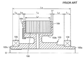
- the motor shaft 103, the rotor 106, and the bearings 104 and 105 shown in FIG. 5 are taken out and enlarged in FIG.
- the present inventor has found that there is a further improvement in the conventional in-wheel motor drive device. 1stly, since an in-wheel motor drive device is arrange
- the motor torque is close to the motor size, it is difficult to increase it in the radial direction due to the restriction that it is installed in the road wheel, and it is necessary to extend it in the axial direction in order to secure the torque. That is, referring to FIG. 6, it is required to shorten the shaft length Ls of the motor shaft 103 from the viewpoint of arrangement, but from the viewpoint of securing the torque, the bearing span of the bearing that rotatably supports both ends of the motor shaft is shortened. It is difficult to do.
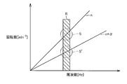
- the speed of the vehicle (automobile) equipped with the in-wheel motor drive device varies from 0 km / h to a high speed range of 100 km / h or higher. For this reason, the rotation speed of the motor shaft of the in-wheel motor drive device varies greatly in the range of 0 to several tens of thousands [min ⁇ 1 ].
- the resonance frequency (region R) around the suspension device intersects with the rotation n-th order forced vibration component and rotation (n + ⁇ ) -order forced vibration component. (Circle S, S ′) may cause audible vibration and in-vehicle noise, which may cause discomfort to the occupant.
- the rotation n-th order forced vibration that is the origin of all vibrations including the rotation first-order forced vibration component. It is important to suppress the components.
- measures for suppressing vibrations including the rotating primary forced vibration component have not been sufficiently studied, and there is room for improvement.
- the bearing span it may be possible to shorten the bearing span by placing a motor shaft bearing inside the cylindrical rotor.
- the outer periphery of the central portion (hereinafter referred to as the outer periphery of the large diameter portion) of the motor shaft to which the inner peripheral surface of the rotor is fitted is formed in a cylindrical shape, and an annular space is formed at the end of the large diameter portion.
- the outer periphery of the end of the motor shaft (hereinafter referred to as the outer periphery of the small diameter portion) into which the inner ring member of the bearing is fitted is disposed in the annular space in the large diameter portion.
- the present invention can secure the motor torque while shifting the forced vibration component of the motor shaft and shortening the bearing span, without using a dedicated grindstone, and without changing the chucking.
- An object of the present invention is to provide a wheel drive motor capable of polishing the outer periphery of a small diameter portion and the outer periphery of a large diameter portion with a chuck.
- the wheel driving motor includes a motor shaft having one side in the axial direction having a smaller diameter than the central portion in the axial direction, and a bearing that rotatably supports a small diameter portion on one side in the axial direction of the motor shaft.
- a rotor that is fixed to the outer peripheral surface of the large-diameter portion located in the axial center of the motor shaft and that faces the stator, and outputs a driving force for rotating the wheel from the motor shaft.
- One end portion in the direction projects from the one end surface in the axial direction of the large diameter portion toward the small diameter portion in the axial direction.
- the axial dimension of the rotor can be made larger than the axial dimension of the motor shaft large diameter portion. Therefore, the first problem described above is solved, and the bearing span of the motor shaft is reduced by shortening the axial dimension of the large-diameter portion of the motor shaft while ensuring sufficient motor torque without changing the axial dimension of the rotor. Can be shortened.
- the outer peripheral surface of the large-diameter portion and the outer peripheral surface of the small-diameter portion can be polished by one chucking without changing the motor shaft in the polishing process of the motor shaft, in the balance correction of the rotating body (motor shaft),
- the coaxiality of the central axis of the large-diameter portion that becomes the mass portion of the motor shaft and the central axis of the small-diameter portion that becomes the bearing portion of the motor shaft can be ensured. Therefore, the balance of the rotating body (motor shaft) can be reliably corrected, and consequently the absolute values of the rotational n-order forced vibration component and the rotational (n + ⁇ ) -order forced vibration component serving as the excitation source can be reduced.
- the second problem described above is solved, and the NVH characteristics that cause discomfort to the occupant are improved.
- the outer peripheral surface of the large diameter portion and the outer peripheral surface of the small diameter portion can be polished with one chuck without changing the motor shaft in the motor shaft polishing step.
- Such polishing can be performed with a general-purpose cylindrical grindstone. Therefore, the third and fourth problems described above are solved, and the concentricity between the outer periphery of the small diameter portion and the outer periphery of the large diameter portion is not impaired, which is advantageous in accuracy and manufacturing cost.
- the large diameter portion of the present invention only needs to have a larger diameter than the small diameter portion, but as a preferred embodiment, the outer diameter size of the large diameter portion is larger than the outer diameter size of the bearing, and one end portion in the axial direction of the rotor is It is good to protrude in the axial direction small diameter part side rather than the axial direction other end part of a bearing. According to this embodiment, the axial position of the bearing overlaps with the axial position of one end in the axial direction of the rotor, and the bearing span of the motor shaft can be shortened.
- the outer peripheral surface of the large-diameter portion includes a large-diameter portion fitting surface that engages with the inner-diameter side portion of the rotor, and the small-diameter portion is fitted to the outer ring member of the bearing on the outer periphery Has a surface.
- the large diameter part fitting surface and the small diameter part fitting surface are good to arrange
- the axial position of the large-diameter portion fitting surface may overlap with the axial position of the small-diameter portion fitting surface.
- the motor shaft is changed and the large-diameter portion is fitted with two chucks.
- the surface and the small-diameter portion fitting surface must be polished individually, or the small-diameter portion fitting surface must be polished with a dedicated grindstone, which is disadvantageous in terms of accuracy or manufacturing cost.
- the rotor can be securely fixed to the large diameter portion so that the rotor does not move in the axial direction. It is sufficient to form a flange portion at the other axial end of the large diameter portion and attach the end member only to one axial end of the large diameter portion.
- the end member can be attached and fixed to both ends in the axial direction of the large diameter portion.
- the end member is positioned so as to be coaxial with the motor shaft at the attachment portion with the large-diameter portion, and is fitted to the inner diameter side portion at one end in the axial direction of the rotor. You may have a fitting outer peripheral surface to match.
- an end member having a lubricating oil passage may be further provided between the end member and one end surface in the axial direction of the rotor.
- the inside of the motor can be lubricated.
- a wheel drive motor according to the present invention, an input shaft coupled to the motor shaft, a speed reduction unit having an output shaft that decelerates and outputs the rotation of the input shaft, and a wheel having a wheel hub coupled to the output shaft
- You may comprise an in-wheel motor drive device by providing a hub bearing part.
- the in-wheel motor drive device can be housed in the space area inside the road wheel, and the wheel drive motor can be installed without difficulty in a narrow wheel housing or in a vehicle body with large layout constraints. it can.
- the outer peripheral surface of the small diameter portion and the large diameter portion can be polished with one chuck without bringing back the motor shaft.
- the dedicated grindstone is not required, and the outer peripheral surface of the small diameter portion and the large diameter portion of the motor shaft can be polished using a general-purpose cylindrical grindstone.
- FIG. 1 is a longitudinal sectional view showing an in-wheel motor drive apparatus that employs a wheel drive motor according to an embodiment of the present invention.
- FIG. 2 is a longitudinal sectional view showing the motor shaft, rotor, and bearing of FIG.
- FIG. 3 is a longitudinal sectional view showing the motor shaft of FIG.
- the in-wheel motor drive device 21 includes a motor unit A that generates a driving force, a deceleration unit B that decelerates and outputs the rotation of the motor unit A, and an output from the deceleration unit B as driving wheels. And a wheel hub bearing portion C for transmitting to the wheel. And it arrange
- the motor part A is accommodated in the motor casing 22a, the pump casing 22p, the motor cover 22t, and the cover cap 22u that form the outline of the motor part A
- the reduction part B is accommodated in the reduction part casing 22b that forms the outline of the reduction part B.
- the wheel hub bearing portion C is a rolling bearing including a wheel hub 32 and a bearing outer ring 22c described later.
- the motor casing 22a, the pump casing 22p, the motor cover 22t, the cover cap 22u, the speed reducer casing 22b, and the bearing outer ring 22c are coupled to each other to form one casing 22.
- the in-wheel motor drive device 21 is installed in a wheel housing of an electric vehicle, for example, together with a wheel (not shown).
- the motor part A includes a stator 23 fixed to the inner periphery of a cylindrical motor casing 22 a, a rotor 24 disposed at a position facing the inside of the stator 23 via a gap opened in the radial direction, and the rotor 24.
- This is a radial gap motor including a rotating motor shaft 35.
- an axial gap motor may be used.
- the rotor 24 is formed by laminating a plurality of flat ring-shaped steel discs 24 m in the direction of the axis O, and a pair of end members having a disc ring shape at both ends of the rotor 24. 38 is provided. These steel discs 24m and end members 38 laminated in the axial direction constitute a cylindrical body. The cylindrical body is disposed between a flange portion 35 f formed on the motor shaft 35 and a flange-shaped end member 39 attached and fixed to the motor shaft 35.
- the end member 39 is provided with a female screw hole, and one end member 38, a plurality of steel disks 24m, the other end member 38, and the flange portion 35f have small holes or notches, respectively.
- the bolt 37 is passed from the flange portion 35f side, and the head portion 37n of the bolt 37 protrudes outward from the flange portion 35f.
- a male screw formed on the outer periphery of the front end portion of the bolt 37 is screwed into a female screw hole formed in the end member 39.
- the end member 39, the one end member 38, the plurality of steel discs 24m, and the other end member 38 are firmly attached to the large-diameter portion 35d that is the central portion in the axial direction of the motor shaft 35.
- the plurality of steel disks 24m and the pair of end members 38 are clamped in the axial direction by the end member 39 and the flange portion 35f.
- a groove 59u extending in the radial direction is formed on the end surface of each end member 38 that contacts the rotor 24.
- the groove 59u is covered with the end face of the rotor 24, and constitutes a lubricating oil passage which will be described later.
- the motor casing 22a extends in the direction of the axis O of the motor shaft 35 as shown in FIG.
- the pump casing 22p integrally formed with one end of the motor casing 22a has a substantially disc shape with a central hole, and forms a boundary with the speed reduction portion B at one end in the axis O direction of the motor portion A, and a bearing.
- One end of the motor shaft 35 is rotatably supported via 36b.
- the bearing 36b is a known rolling bearing having an outer ring member, an inner ring member, and a plurality of rolling elements, but is not limited to such a configuration.
- the inner ring member of the bearing 36b is fixed to the outer peripheral surface of one end portion of the motor shaft 35 by fitting.
- the pump casing 22p includes an oil pump 51 in the central portion.
- An annular groove 22g is formed on the end surface of the pump casing 22p directed to the motor part A.
- the annular groove 22g receives the stator coil 23c protruding from the stator 23 in the axis O direction.
- a central portion 22i of the pump casing 22p protrudes toward the inner diameter side space of the rotor 24 that is a cylindrical body.
- the outer ring member of the bearing 36b is attached and fixed to the inner peripheral surface of the center hole formed in the center portion 22i.
- the motor cover 22t attached and fixed to the other end of the motor casing 22a has a substantially disc shape with a central hole, and forms the end face of the motor portion A at the other end in the axis O direction of the motor portion A, and a bearing 36a.
- the other end portion of the motor shaft 35 is rotatably supported via the.
- the motor cover 22t is an end portion of the motor part A and also an end portion of the in-wheel motor drive device 21.
- the bearing 36a is a known rolling bearing having an outer ring member, an inner ring member, and a plurality of rolling elements, but is not limited to such a configuration.
- the inner ring member of the bearing 36a is fixed to the outer peripheral surface of the other end portion of the motor shaft 35 by fitting.
- the outer ring member of the bearing 36a is attached and fixed to the inner peripheral surface of the central hole formed in the motor cover 22t.
- a rotational speed sensor 34 is disposed at a position in the axis O direction between the bearing 36 a and the rotor 24.
- the rotation speed sensor 34 (detection side) is supported by the bracket 22v of the motor cover 22t protruding toward the rotor 24, and faces the sensor rotor (detection side) attached to the outer peripheral surface of the motor shaft 35.
- a cover cap 22u is attached to the motor cover 22t to close the central hole of the motor cover 22t and cover the end surface of the motor shaft 35.
- small diameter portions 35 a and 35 b having predetermined outer diameters are formed at both ends of the motor shaft 35.
- a cylindrical large-diameter portion 35d having a predetermined outer diameter that is sufficiently larger than the small-diameter portions 35a and 35b is formed.
- the large-diameter portion 35d is connected to the shaft portion of the motor shaft 35 (straight shaft portion from the small-diameter portion 35a to the small-diameter portion 35b) via a coupling portion 35c extending in the inner-diameter direction from the central portion in the axial direction of the large-diameter portion 35d. To do. Then, both end portions in the axial direction of the large diameter portion 35d are cantilevered by the coupling portion 35c. A flange portion 35f that protrudes further to the outer diameter side is formed at the end portion on the small diameter portion 35a side of the large diameter portion 35d. On the other hand, the end member 39 is attached and fixed to the end of the large diameter portion 35d on the small diameter portion 35b side.
- the bearing 36b rotatably supports the small diameter portion 35b which is one end portion of the motor shaft 35.
- the bearing 36a rotatably supports the small diameter portion 35a which becomes the other end portion of the motor shaft 35.
- the inner peripheral surface 24 i of the rotor 24 is fitted to the outer peripheral surface 35 j of the large-diameter portion 35 d that becomes the central portion of the motor shaft 35.
- a notch formed on the inner periphery of the steel disk 24 m is continuous to form a groove that avoids interference with the bolt 37.
- a groove 59t constituting a lubricating oil passage described later is formed in the outer peripheral surface 35j.
- axial dimension Lr of the rotor 24 is greater than the axial dimension L 2 of the outer peripheral surface 35j.
- the dimension Lr shown in FIG. 2 represents the axial length of a region sandwiched between the flange portion 35f of the large diameter portion 35d and the flange portion of the end member 39. That is, in FIG.
- the outer diameter of the large diameter portion 35d is sufficiently larger than the outer diameter of the small diameter portion 35b and sufficiently larger than the outer diameter of the bearing 36b.
- the axial position of the bearing 36 b overlaps with the axial position of the one end 24 p in the axial direction of the rotor 24. As a result, the distance from one bearing 36b to the other bearing 36a is shortened, the bearing span of the motor shaft 35 is shortened, and the axial dimension of the motor portion A can be shortened.
- the outer peripheral surface 35j which is a fitting surface with the rotor 24, is shorter in the axial direction than the rotor 24.
- the end member 39 presses the one end 24p in the axial direction of the rotor 24 in the axial direction. Does not occur.
- One end member 38 is separated from the outer peripheral surface 35j, but is supported by the end member 39, so that there is no problem in attaching the end member.
- the outer peripheral surface 35j of the large diameter portion 35d includes a large diameter portion fitting surface that fits with the inner diameter side portion of the rotor 24.
- the small-diameter portion 35a has a small-diameter portion fitting surface 35h that fits with the inner ring member of the bearing 36a on the outer periphery.
- the small-diameter portion 35b has a small-diameter portion fitting surface 35i that fits with the inner ring member of the bearing 36b on the outer periphery.
- the outer peripheral surface 35j that becomes the large-diameter portion fitting surface and the small-diameter portion fitting surface 35i are arranged adjacent to each other so that the positions in the axial direction do not overlap.
- the grindstone can be applied to the outer peripheral surface 35j and the small diameter portion fitting surface 35i from the outside in the radial direction without holding the motor shaft 35 while being chucked. Can do.
- the small-diameter portion fitting surface 35i and the large-diameter portion outer peripheral surface 35j of the present embodiment are continuously disposed in the axial direction as indicated by the axial dimensions L 3 and L 2 , and therefore, the bearing span of the motor shaft. Can be made shorter than before. This is because the conventional motor shaft 103 has a distance Lq between the bearing 105 and the rotor 106, as shown in FIG.
- FIG. 1 a comparative example is shown in FIG.
- the large-diameter portion fitting surface 135j and the small-diameter portion fitting surface 135i overlap in the axial direction position. For this reason, in the surface polishing process of the motor shaft 135, the motor shaft 135 is chucked and the grindstone is applied to the large-diameter portion fitting surface 135j from the outside in the radial direction. It must be applied to the fitting surface 135i.
- the outer peripheral surface 35j and the small-diameter fitting surface 35i can be simultaneously polished with one chuck, and the outer peripheral surface 35j and the small-diameter fitting are fitted. This is advantageous in terms of both high accuracy and cost of concentricity of the mating surface 35i.
- the end member 39 is fixedly attached to one end surface 35e in the axial direction of the large-diameter portion 35d, protrudes from the one end surface 35e in the axial direction in the axial direction, and then flanges toward the outer diameter direction. spread. That is, the end member 39 faces the flange portion 35f with the inner diameter side portion of the rotor 24 and the pair of end members 38 interposed therebetween.
- the end member 39 is a ring-shaped member including a cylindrical portion and a flange portion, and a cross section cut along a plane including the central axis (axis O) has an L shape (see FIG. 2).
- a fitting surface 35g that is processed with high accuracy so as to be concentric with the axis O of the motor shaft 35 is formed at one end in the axial direction of the large diameter portion 35d.
- the fitting surface 35g is a peripheral surface, and when the surface to be joined of the ring-shaped end member 39 is fitted to the fitting surface 35g, the end member 39 is positioned so as to be concentric with the axis O.
- the fitting surface 35g of this embodiment is an inner peripheral surface
- the to-be-joined surface of the end member 39 is an outer peripheral surface, you may reverse the internal / external relationship of this peripheral surface.
- the end member 39 has a fitting outer peripheral surface 39j that fits with the inner diameter side portion of the one end 24p in the axial direction of the rotor 24.
- the rotor 24 is positioned with high accuracy so as to be concentric with the axis O by the outer peripheral surface 35j and the fitting outer peripheral surface 39j fitted to the inner diameter side portion of the rotor 24.
- the fitting outer peripheral surface 39j fits not only with the inner peripheral surface 24i of the rotor 24 but also with the inner peripheral surface of one end member 38.
- the one end member 38 is also positioned with high accuracy so that the rotor 24 is concentric with the axis O by the fitting outer peripheral surface 39j.
- the other end member 38 is also positioned with high accuracy so that the rotor 24 is concentric with the axis O by the outer peripheral surface 35j of the large diameter portion 35d.
- one end of the motor shaft 35 is coupled to a speed reducer input shaft 25 that is rotatably provided inside the speed reducer B.
- One end of the speed reduction part input shaft 25 on the side far from the motor part A is rotatably supported by an end part of a speed reduction part output shaft 28 described later via a bearing 36d.
- the other end of the speed reducing unit input shaft 25 on the side close to the motor unit A is coupled to one end of the motor shaft 35.
- a central portion of the speed reduction portion input shaft 25 is rotatably supported by a reinforcing member 61 described later via a bearing 36c.
- the bearings 36c and 36d are known rolling bearings having an outer ring member, an inner ring member, and a plurality of rolling elements.
- Eccentric portions 25a and 25b are formed eccentrically from the axis O on the outer periphery of the deceleration portion input shaft 25.
- the two disc-shaped eccentric portions 25a and 25b are arranged apart from each other in the direction of the axis O, and are provided with a phase difference of 180 ° in the circumferential direction so as to cancel out vibrations generated by centrifugal force due to the eccentric motion.
- the motor shaft 35 and the speed reduction part input shaft 25 constitute a motor side rotation member that transmits the driving force of the motor part A to the speed reduction part B.
- the speed reduction part B is a cycloid speed reducer and is coaxially arranged on one side in the axis O direction of the motor part A, and has a cylindrical speed reduction part casing 22b and an outer pin holding part 45 fixed to the speed reduction part casing 22b.
- Deceleration part input shaft 25 eccentric parts 25a, 25b coupled to deceleration part input shaft 25
- curved plates 26a, 26b as revolving members rotatably held by eccentric parts 25a, 25b, and curved plates 26a, 26b
- a rolling bearing 41 is provided in an annular space between the outer periphery of the eccentric portion 25a and the inner periphery of the curved plate 26a.
- a rolling bearing 41 is also provided between the outer periphery of the eccentric portion 25b and the inner periphery of the curved plate 26b.
- the deceleration part output shaft 28 has a flange part 28a on the motor part A side and a shaft part 28b on the wheel hub bearing part C side.
- a circular recess for receiving one end of the speed reducing portion input shaft 25 is formed at the center of the flange portion 28a, and an outer ring member of the bearing 36d is attached and fixed to the inner peripheral surface of the circular recess.
- holes for fixing one end portions of the inner pins 31 are formed at equal intervals on the circumference around the axis O of the speed reduction portion output shaft 28.
- a wheel hub 32 is connected and fixed to the outer peripheral surface of the shaft portion 28b.
- the speed reduction part output shaft 28 and the wheel hub 32 constitute a wheel side rotation member that transmits the driving force of the speed reduction part B to the drive wheels.
- the outer pins 27 are installed at equal intervals in the circumferential direction with the axis O as the center.
- the curved plates 26a and 26b engaged with the outer pin 27 revolve around the axis O according to the movement of the eccentric portions 25a and 25b, and in the direction opposite to the revolution direction. Rotate slightly.
- the inner pin 31 is passed through a through hole formed in the curved plates 26a and 26b, and has an outer diameter that is sufficiently smaller than the inner diameter of the through hole.
- the inner pin 31 takes out only the rotational motion of the curved plates 26 a and 26 b and transmits it to the speed reduction portion output shaft 28.
- the rotational speed of the speed reducing part output shaft 28 with respect to the speed of the speed reducing part input shaft 25 is reduced by more than 1/10. According to the reduction part B of this embodiment, it is compact and can obtain a high reduction ratio.
- a reinforcing member 61 is provided at the other end portion of the inner pin 31 on the side away from the flange portion 28a.
- the reinforcing member 61 includes a flange-shaped annular portion 61b coupled to the tips of the plurality of inner pins 31, and a cylindrical portion 61c extending from the inner peripheral edge of the annular portion 61b to the motor portion A in the axial direction. Since the load applied to a part of the inner pins 31 from the two wire plates 26a, 26b is supported by all the inner pins 31 through the annular portion 61b, the stress acting on the inner pins 31 is reduced and durability is improved. Can be improved.
- the tip of the cylindrical portion 61 c is inserted into the oil pump 51 to drive the oil pump 51.
- the oil pump 51 is connected to a suction oil passage 52 and a discharge oil passage 54 provided in the wall of the pump casing 22p, and supplies lubricating oil from an oil reservoir 53 provided in a lower portion of the speed reduction portion B through the suction oil passage 52.
- the suction and discharge oil passage 54 discharges the lubricating oil.
- the discharge oil passage 54 is provided in the motor casing 22a to cool the lubricating oil, the communication oil passage 56a provided in the wall of the motor cover 22t, and the wall of the cover cap 22u.
- a branch oil passage 58a extending outward and a branch oil passage 58b extending in the eccentric portion 25b in the same manner and a hole 43 formed in the inner ring member 42 fitted to the outer periphery of each of the eccentric portions 25a and 25b are sequentially connected. .
- the lubricating oil discharged from the oil pump 51 sequentially flows through these oil passages 54, 55, 56a, 56b, 57, 58a (58b) and the hole 43, and inside the speed reduction part B (the rolling bearing 41, the curved plates 26a, 26b).
- the inner pin 31, the outer pin 27, the bearings 36c, 36d, etc.) are lubricated.
- the lubricating oil after lubrication falls and passes through a through hole 45h formed in the lower part of the outer pin holding part 45 and a through hole 53h formed in the lower part of the speed reduction part casing 22b, and the lower part of the speed reduction part casing 22b. Gathers in an oil sump 53 attached to the Then, it is sucked again by the oil pump 51 and circulates inside the in-wheel motor drive device 21.
- the motor shaft 35 is formed with a rotor oil passage 59 that branches off from the axial oil passage 57 and extends in the radial direction.
- the rotor oil passage 59 is formed inside the coupling portion 35c and extends from the axial oil passage 57 in the outer diameter direction, a groove 59t connected to the hole 59s, and a groove 59u extending from the end of the groove 59t in the outer diameter direction. including.
- the outer diameter side end of the groove 59u is an opening.
- Lubricating oil that branches off from the axial oil passage 57 and flows through the rotor oil passage 59 is injected into the motor casing 22a and lubricates the inside of the motor portion A (bearings 36a, 36b, etc.).
- the lubricated lubricating oil falls, passes through a through hole 53 i that penetrates the lower part of the pump casing 22 p, and collects in the oil reservoir 53.
- the in-wheel motor drive device 21 of the present embodiment includes the lubricating oil circuit of the shaft center oil supply system and injects lubricating oil from the input shaft 25. Then, the lubricating oil flows radially outward from the input shaft 25 and lubricates the motor part A and the speed reducing part B.
- a bearing 36 b that rotatably supports a small diameter portion 35 b on one side in the axial direction of the motor shaft 35 and a large portion on the other side (center portion) in the axial direction of the motor shaft 35.
- the one axial end portion 24p of the rotor 24 is closer to the small diameter portion 35b side than the one axial end surface 35e of the large diameter portion 35d.
- the axial dimension Lr of the rotor 24 it is possible to be larger than the axial dimension L 2 of the outer peripheral surface 35j (Lr> L 2). Therefore, the motor torque necessary for driving the wheels can be ensured.
- the shaft length Ls of the motor shaft 35 is shorter than that of the conventional motor, and the bearing span can be shortened as compared with the conventional motor.
- FIG. 3 showing a motor shaft 35 of this embodiment for comparison, compared to Figure 6 showing a conventional motor shaft 103, axial length Ls of the motor shaft 35, the axial dimension L 1 of the bearing 36a, a bearing 36a a distance Lp to the flange portion 35f of the thickness Lf of the flange portion 35f, the axial dimension L 2 of the outer peripheral surface 35j, the sum of the axial dimension L 3 of the bearing 36b.
- the axial dimension Lr of the conventional rotor 106 is smaller than the axial dimension L 2 of the outer peripheral surface portion of the rotor 106 and a pair of end members 109 of the motor shaft 103 is mounted and fixed, axial dimension L 2 was not fully utilized.
- the dimension Lr shown in FIG. 6 indicates the dimension in the axial direction of the rotor 106 alone. Assuming that the dimension Lr here also indicates the dimension obtained by adding the axial dimension of the rotor 106 itself and the axial dimension of the inner diameter side portion of the pair of end members 109, the conventional rotor 106. Dimension Lr becomes substantially the same as the axial dimension L 2 of the outer peripheral surface of the central portion of the motor shaft 103 (the large diameter portion) 103b.
- the outer diameter dimension of the large diameter portion 35 d is larger than the outer diameter dimension of the bearing 36 b, and the axial position of the bearing 36 b is the axial end position 24 p of the rotor 24. Overlap with the axial position. Thereby, the axial length of the motor shaft 35 can be further shortened while sufficiently securing the axial dimension Lr of the rotor 24.
- the outer peripheral surface 35j of the large diameter portion 35d includes the large diameter portion fitting surface 35k that fits the inner diameter side portion of the rotor 24, and the small diameter portion 35b is a bearing on the outer periphery. It has a small diameter portion fitting surface 35i that fits with the inner ring member 36b. And the large diameter part fitting surface 35k and the small diameter part fitting surface 35i are arrange
- the large-diameter portion fitting surface 35k and the small-diameter portion fitting surface 35i are the position of one end in the axial direction of the large-diameter portion fitting surface 35k (outer peripheral surface 35j) and the small-diameter portion fitting surface 35i.
- these positions may be slightly apart.
- the large-diameter portion fitting surface 35k and the small-diameter portion fitting surface 35i are adjacent to each other in the axial direction so that at least the axial position of the small-diameter portion fitting surface 35i overlaps the axial position of the end member 39. As long as they are arranged. More specifically, the position of the other end in the axial direction of the small diameter portion fitting surface 35i is divided by the position of one end in the axial direction of the large diameter portion fitting surface 35k and the position of one end in the axial direction of the end member 39. What is necessary is just to be arrange
- the end member 39 that is attached and fixed to the large diameter portion 35d, protrudes in the axial direction from one end surface in the axial direction of the large diameter portion 35d, and covers the one end surface in the axial direction of the rotor 24.
- the position of the rotor 24 in the axial direction is regulated so that the rotor 24 does not shift in the axial direction.
- the end member 39 is positioned so as to be coaxial with the axis O of the motor shaft 35 at the fitting surface 35g with the large diameter portion 35d, and the inner diameter side portion of the one end 24p in the axial direction of the rotor 24 And a fitting outer peripheral surface 39j to be fitted.
- the rotor 24 is positioned with high accuracy so as to be concentric with the axis O.
- the motor part A can be lubricated.
- the end member 38 may not be provided between at least one of the rotor 24 and the end member 39 and between the rotor 24 and the flange portion 35f of the large diameter portion 35d.
- the wheel drive motor and in-wheel motor drive device according to the present invention are advantageously used in electric vehicles and hybrid vehicles.
Abstract
This wheel-driving motor is provided with: a motor shaft (35) having one axial side having a smaller diameter than the axial center section of the motor shaft (35); a bearing (36b) for rotatably supporting the small-diameter section (35b) of the motor shaft, which is located on the one axial side; and a rotor (24) affixed to the outer peripheral surface (35j) of the large-diameter section (35d) of the motor shaft, which is located at the axial center section of the motor shaft, and facing a stator. The wheel-driving motor outputs a drive force from the motor shaft, the drive force rotating a wheel. The wheel-driving motor is characterized in that one axial end section (24p) of the rotor axially protrudes further toward the axial small-diameter section (35b) than one axial end surface (35e) of the large-diameter section.
Description
本発明は、インホイールモータ駆動装置等に内蔵され、車輪を駆動する車輪駆動用モータに関する。
The present invention relates to a wheel drive motor that is built in an in-wheel motor drive device or the like and drives a wheel.
車輪を駆動する車輪駆動用モータとしては従来、例えば、特開2012-148725号公報(特許文献1)および特開2009-063043号公報(特許文献2)に記載のごときインホイールモータ駆動装置が知られている。特許文献1および特許文献2に記載のインホイールモータ駆動装置101は、図5に示すように、モータを内蔵するモータ部101Aと、サイクロイド減速機を内蔵する減速部101Bと、車輪ハブ108を回転自在に支持する車輪ハブ軸受部101Cとを備える。モータ部101Aのモータケーシング102は、モータ軸103の両端部103a,103cを転がり軸受104,105で回転自在に支持する。モータ軸103の中央部103bの外周面には、円筒形状のロータ106を連結固定する。ロータ106の外周面は、モータケーシング102の内周に固定されたステータ107の内周面と対面する。モータ軸103の回転はサイクロイド減速機(減速部101B)で1/10を超える高い減速比で減速されて車輪ハブ108を駆動する。このようにサイクロイド減速機は、遊星歯車減速機や平行軸歯車減速機等の一般的な減速機と比較して、コンパクトでありながらも減速比が高く、有利である。
As a wheel driving motor for driving a wheel, for example, an in-wheel motor driving device as described in JP 2012-148725 A (Patent Document 1) and JP 2009-063043 A (Patent Document 2) has been known. It has been. As shown in FIG. 5, the in-wheel motor drive device 101 described in Patent Literature 1 and Patent Literature 2 rotates a motor portion 101A incorporating a motor, a reduction portion 101B incorporating a cycloid reduction gear, and a wheel hub 108. And a wheel hub bearing portion 101C that is freely supported. The motor casing 102 of the motor unit 101 </ b> A rotatably supports both end portions 103 a and 103 c of the motor shaft 103 with rolling bearings 104 and 105. A cylindrical rotor 106 is connected and fixed to the outer peripheral surface of the central portion 103 b of the motor shaft 103. The outer peripheral surface of the rotor 106 faces the inner peripheral surface of the stator 107 fixed to the inner periphery of the motor casing 102. The rotation of the motor shaft 103 is decelerated at a high reduction ratio exceeding 1/10 by a cycloid reduction gear (deceleration unit 101B) to drive the wheel hub 108. As described above, the cycloid reduction gear is advantageous in that it is compact but has a high reduction ratio as compared with a general reduction gear such as a planetary gear reduction gear or a parallel shaft gear reduction gear.
図5のモータ軸103、ロータ106、および軸受104、105を取り出し、図6に拡大して示す。モータ軸103が最低限必要な軸長Lsは、モータ軸103の端部103aを支持するために必要な軸線方向寸法L1と、モータ軸103の中央部103bの軸線方向寸法L2+Lfと、モータ軸103の端部103cを支持するために必要な軸線方向寸法L3と、端部103aおよび中央部103b間の距離Lpと、中央部103bおよび端部103c間の距離Lqとの合計である(Ls=L3+Lq+L2+Lf+Lp+L1)。
The motor shaft 103, the rotor 106, and the bearings 104 and 105 shown in FIG. 5 are taken out and enlarged in FIG. The minimum shaft length Ls required for the motor shaft 103 is the axial dimension L 1 required to support the end 103 a of the motor shaft 103, the axial dimension L 2 + Lf of the central portion 103 b of the motor shaft 103, and is the sum of the axial dimension L 3 required for supporting an end portion 103c of the motor shaft 103, the distance Lp between the end portion 103a and the central portion 103b, the distance Lq between the central portion 103b and the end portion 103c (Ls = L 3 + Lq + L 2 + Lf + Lp + L 1).
しかし、上記従来のようなインホイールモータ駆動装置にあっては、さらに改善すべき点があることを本発明者は見いだした。第1に、インホイールモータ駆動装置は、車輪のロードホイール内に配置されることから、インホイールモータ駆動装置全体がロードホイール内に収容されて、インホイールモータ駆動装置の端部がはみ出さないことが望ましい。そこでモータ軸の両端を支持する軸受スパンを短くすることが要求される。一方で、モータトルクはモータ体格に寄るが、ロードホイール内に設置されるという制約から、径方向に大きくすることは難しく、トルク確保のためには軸方向に延長する必要がある。つまり図6を参照すると、配置の観点からモータ軸103の軸長Lsを短くすることが要求されるが、トルク確保の観点からモータ軸の両端部を回転自在に支持する軸受の軸受スパンを短くすることは困難である。
However, the present inventor has found that there is a further improvement in the conventional in-wheel motor drive device. 1stly, since an in-wheel motor drive device is arrange | positioned in the road wheel of a wheel, the whole in-wheel motor drive device is accommodated in a road wheel, and the edge part of an in-wheel motor drive device does not protrude. It is desirable. Therefore, it is required to shorten the bearing span that supports both ends of the motor shaft. On the other hand, although the motor torque is close to the motor size, it is difficult to increase it in the radial direction due to the restriction that it is installed in the road wheel, and it is necessary to extend it in the axial direction in order to secure the torque. That is, referring to FIG. 6, it is required to shorten the shaft length Ls of the motor shaft 103 from the viewpoint of arrangement, but from the viewpoint of securing the torque, the bearing span of the bearing that rotatably supports both ends of the motor shaft is shortened. It is difficult to do.
第2に、インホイールモータ駆動装置を搭載した車両(自動車)の速度は、0km/hから100km/h以上の高速域まで変化する。そのため、インホイールモータ駆動装置のモータ軸の回転数が、0~数万[min-1]の範囲で大きく変動する。インホイールモータ駆動装置が取り付けられる懸架装置に着目すると、図7を参照して懸架装置周辺の共振周波数(領域R)と回転n次強制振動成分や回転(n+α)次強制振動成分が交差するポイント(丸囲いS,S’)では、可聴域の振動および車内騒音を引き起こし、乗員に不快感を与える可能性がある。従って、インホイールモータ駆動装置を搭載した車両の静粛性(NVH特性 Noise Vibration Harshness)を向上するためには、回転1次強制振動成分をはじめとする全ての振動の由来となる回転n次強制振動成分を抑制することが重要である。しかしながら、従来のインホイールモータ駆動装置では回転1次強制振動成分をはじめとする振動の抑制対策について十分に検討されておらず、改善の余地を残している。
Second, the speed of the vehicle (automobile) equipped with the in-wheel motor drive device varies from 0 km / h to a high speed range of 100 km / h or higher. For this reason, the rotation speed of the motor shaft of the in-wheel motor drive device varies greatly in the range of 0 to several tens of thousands [min −1 ]. When attention is paid to the suspension device to which the in-wheel motor drive device is attached, referring to FIG. 7, the resonance frequency (region R) around the suspension device intersects with the rotation n-th order forced vibration component and rotation (n + α) -order forced vibration component. (Circle S, S ′) may cause audible vibration and in-vehicle noise, which may cause discomfort to the occupant. Therefore, in order to improve the quietness (NVH characteristic Noise Vibration Harshness) of the vehicle equipped with the in-wheel motor drive device, the rotation n-th order forced vibration that is the origin of all vibrations including the rotation first-order forced vibration component. It is important to suppress the components. However, in the conventional in-wheel motor drive device, measures for suppressing vibrations including the rotating primary forced vibration component have not been sufficiently studied, and there is room for improvement.
第3に、円筒形状のロータ内部にモータ軸の軸受を配置して軸受スパンを短くすることが考えられる。具体的には、ロータの内周面が嵌合するモータ軸の中央部外周(以下、大径部外周という)を円筒状に形成しておき、大径部の端部に環状空間を形成する。そして大径部内の環状空間に、軸受の内輪部材が嵌合するモータ軸の端部外周(以下、小径部外周という)を配置する。この場合にはモータ軸の研磨工程において、小径部外周と大径部外周を研磨する際にいわゆるツーチャックの手順が必要となり、小径部外周および大径部外周を同時研磨することができない。つまり小径部外周の軸線方向位置と大径部外周の軸線方向位置が重なるため、まずモータ軸の所定箇所をチャッキングして小径部外周を研磨し、次に持ち替えてモータ軸の別な箇所をチャッキングして大径部外周を研磨する必要がある。そうすると2度のチャッキングによって小径部外周と大径部外周の同心度が損なわれる恐れがある。
Third, it may be possible to shorten the bearing span by placing a motor shaft bearing inside the cylindrical rotor. Specifically, the outer periphery of the central portion (hereinafter referred to as the outer periphery of the large diameter portion) of the motor shaft to which the inner peripheral surface of the rotor is fitted is formed in a cylindrical shape, and an annular space is formed at the end of the large diameter portion. . Then, the outer periphery of the end of the motor shaft (hereinafter referred to as the outer periphery of the small diameter portion) into which the inner ring member of the bearing is fitted is disposed in the annular space in the large diameter portion. In this case, in the motor shaft polishing step, a so-called two-chuck procedure is required when polishing the outer periphery of the small diameter portion and the outer periphery of the large diameter portion, and the outer periphery of the small diameter portion and the outer periphery of the large diameter portion cannot be simultaneously polished. In other words, since the axial position of the outer periphery of the small diameter portion and the axial position of the outer periphery of the large diameter portion overlap each other, first chuck the predetermined portion of the motor shaft, polish the outer periphery of the small diameter portion, and then change it to replace another portion of the motor shaft. It is necessary to polish the outer periphery of the large diameter portion by chucking. Then, the concentricity of the outer periphery of the small diameter portion and the outer periphery of the large diameter portion may be impaired by the two times of chucking.
第4に、大径部の内部の空間に挿入可能な専用砥石を用いて、チャッキングの持ち替えを伴うことなく小径部外周を研磨することが考えられるが、専用砥石は管理コストアップの原因となる。
Fourthly, it is conceivable to grind the outer periphery of the small diameter part without changing the chucking using a special grindstone that can be inserted into the space inside the large diameter part. Become.
本発明は、上述の実情に鑑み、モータ軸の強制振動成分をずらし、軸受スパンを短くしつつもモータトルクを確保することができ、専用砥石を使用することなく、チャッキングを持ち替えることなくワンチャックで小径部外周および大径部外周を研磨することができる車輪駆動モータを提供することを目的とする。
In view of the above situation, the present invention can secure the motor torque while shifting the forced vibration component of the motor shaft and shortening the bearing span, without using a dedicated grindstone, and without changing the chucking. An object of the present invention is to provide a wheel drive motor capable of polishing the outer periphery of a small diameter portion and the outer periphery of a large diameter portion with a chuck.
この目的のため本発明による車輪駆動用モータは、軸線方向一方側が軸線方向中央部よりも小径に形成されたモータ軸と、モータ軸の軸線方向一方側の小径部を回転自在に支持する軸受と、モータ軸の軸線方向中央部に位置する大径部の外周面に固定されてステータと対面するロータとを備え、モータ軸から車輪を回転するための駆動力を出力するモータにおいて、ロータの軸線方向一方端部が大径部の軸線方向一方端面から軸線方向小径部側に突出することを特徴とする。
For this purpose, the wheel driving motor according to the present invention includes a motor shaft having one side in the axial direction having a smaller diameter than the central portion in the axial direction, and a bearing that rotatably supports a small diameter portion on one side in the axial direction of the motor shaft. A rotor that is fixed to the outer peripheral surface of the large-diameter portion located in the axial center of the motor shaft and that faces the stator, and outputs a driving force for rotating the wheel from the motor shaft. One end portion in the direction projects from the one end surface in the axial direction of the large diameter portion toward the small diameter portion in the axial direction.
かかる本発明によれば、ロータの軸線方向寸法をモータ軸大径部の軸線方向寸法よりも大きくすることができる。したがって上述した第1の課題が解決され、ロータの軸線方向寸法を変化させることなく十分なモータトルクを確保しつつも、モータ軸大径部の軸線方向寸法を短くすることによりモータ軸の軸受スパンを短縮することができる。またモータ軸の研磨工程においてモータ軸を持ち替えることなく1度のチャッキングで大径部の外周面および小径部の外周面を研磨することができることから、回転体(モータ軸)のバランス修正において、モータ軸の質量部になる大径部の中心軸と、モータ軸の軸受部になる小径部の中心軸の同軸度を確保することができる。したがって確実に回転体(モータ軸)のバランス修正を行うことが可能となり、ひいては、加振源となる回転n次強制振動成分や回転(n+α)次強制振動成分の絶対値を低減できる。この結果、上述した第2の課題が解決され、乗員への不快感を及ぼすNVH特性が改善する。
According to the present invention, the axial dimension of the rotor can be made larger than the axial dimension of the motor shaft large diameter portion. Therefore, the first problem described above is solved, and the bearing span of the motor shaft is reduced by shortening the axial dimension of the large-diameter portion of the motor shaft while ensuring sufficient motor torque without changing the axial dimension of the rotor. Can be shortened. In addition, since the outer peripheral surface of the large-diameter portion and the outer peripheral surface of the small-diameter portion can be polished by one chucking without changing the motor shaft in the polishing process of the motor shaft, in the balance correction of the rotating body (motor shaft), The coaxiality of the central axis of the large-diameter portion that becomes the mass portion of the motor shaft and the central axis of the small-diameter portion that becomes the bearing portion of the motor shaft can be ensured. Therefore, the balance of the rotating body (motor shaft) can be reliably corrected, and consequently the absolute values of the rotational n-order forced vibration component and the rotational (n + α) -order forced vibration component serving as the excitation source can be reduced. As a result, the second problem described above is solved, and the NVH characteristics that cause discomfort to the occupant are improved.
またモータ軸の研磨工程においてモータ軸を持ち替えることなくワンチャックで大径部の外周面および小径部の外周面を研磨することができる。かかる研磨は汎用の円筒型砥石で可能である。したがって上述した第3および第4の課題が解決され、小径部外周と大径部外周の同心度が損なわれず精度および製造コストにおいて有利である。
Also, the outer peripheral surface of the large diameter portion and the outer peripheral surface of the small diameter portion can be polished with one chuck without changing the motor shaft in the motor shaft polishing step. Such polishing can be performed with a general-purpose cylindrical grindstone. Therefore, the third and fourth problems described above are solved, and the concentricity between the outer periphery of the small diameter portion and the outer periphery of the large diameter portion is not impaired, which is advantageous in accuracy and manufacturing cost.
本発明の大径部は小径部よりも大径であればよいが、好ましい実施形態として、大径部の外径寸法が軸受の外径寸法よりも大きく、ロータの軸線方向一方端部が、軸受の軸線方向他方端部よりも軸線方向小径部側に突出するとよい。かかる実施形態によれば軸受の軸線方向位置がロータの軸線方向一方端部の軸線方向位置に重なり、モータ軸の軸受スパンを短縮することができる。
The large diameter portion of the present invention only needs to have a larger diameter than the small diameter portion, but as a preferred embodiment, the outer diameter size of the large diameter portion is larger than the outer diameter size of the bearing, and one end portion in the axial direction of the rotor is It is good to protrude in the axial direction small diameter part side rather than the axial direction other end part of a bearing. According to this embodiment, the axial position of the bearing overlaps with the axial position of one end in the axial direction of the rotor, and the bearing span of the motor shaft can be shortened.
本発明の好ましい実施形態として、大径部の外周面はロータの内径側部分と嵌合する大径部嵌合面を含み、小径部は外周に軸受の内輪部材と嵌合する小径部嵌合面を有する。そして大径部嵌合面と小径部嵌合面は、軸線方向位置が重ならないよう隣り合って配置されるとよい。ここで好ましくは、大径部嵌合面および小径部嵌合面間の軸線方向距離が開かないよう連続して配置される。他の実施形態として、大径部嵌合面の軸線方向位置と小径部嵌合面の軸線方向位置が重なってもよいが、この場合にはモータ軸を持ち替えてツーチャックで大径部嵌合面と小径部嵌合面を個別に研磨するか、専用砥石で小径部嵌合面を研磨するかしなければならず、精度あるいは製造コストにおいて不利である。
As a preferred embodiment of the present invention, the outer peripheral surface of the large-diameter portion includes a large-diameter portion fitting surface that engages with the inner-diameter side portion of the rotor, and the small-diameter portion is fitted to the outer ring member of the bearing on the outer periphery Has a surface. And the large diameter part fitting surface and the small diameter part fitting surface are good to arrange | position adjacently so that an axial direction position may not overlap. Here, preferably, it arrange | positions continuously so that the axial direction distance between a large diameter part fitting surface and a small diameter part fitting surface may not open. As another embodiment, the axial position of the large-diameter portion fitting surface may overlap with the axial position of the small-diameter portion fitting surface. In this case, the motor shaft is changed and the large-diameter portion is fitted with two chucks. The surface and the small-diameter portion fitting surface must be polished individually, or the small-diameter portion fitting surface must be polished with a dedicated grindstone, which is disadvantageous in terms of accuracy or manufacturing cost.
本発明のさらに好ましい実施形態として、大径部に取付固定されて、大径部の軸線方向一方端面から軸線方向に突出し、ロータの軸線方向一方端面を覆うエンド部材をさらに備えるとよい。かかる実施形態によれば、ロータが軸線方向に動かないよう、大径部に確りと固定することができる。なお大径部の軸線方向他方端にはフランジ部を形成しておき、エンド部材は大径部の軸線方向一方端のみに取り付ければ足りる。あるいはエンド部材を大径部の軸線方向両端に取付固定することも可能である。
As a further preferred embodiment of the present invention, it is preferable to further include an end member attached and fixed to the large-diameter portion, protruding in the axial direction from one end surface in the axial direction of the large-diameter portion, and covering the one end surface in the axial direction of the rotor. According to such an embodiment, the rotor can be securely fixed to the large diameter portion so that the rotor does not move in the axial direction. It is sufficient to form a flange portion at the other axial end of the large diameter portion and attach the end member only to one axial end of the large diameter portion. Alternatively, the end member can be attached and fixed to both ends in the axial direction of the large diameter portion.
本発明は一実施形態に限定されるものではないが、エンド部材は、大径部との取付箇所でモータ軸と同軸となるよう位置決めされ、ロータの軸線方向一方端部の内径側部分と嵌合する嵌合外周面を有してもよい。
Although the present invention is not limited to one embodiment, the end member is positioned so as to be coaxial with the motor shaft at the attachment portion with the large-diameter portion, and is fitted to the inner diameter side portion at one end in the axial direction of the rotor. You may have a fitting outer peripheral surface to match.
本発明の一実施形態としてエンド部材とロータの軸線方向一方端面との間に、潤滑油路を有する端部部材をさらに備えてもよい。かかる実施形態によれば、モータの内部を潤滑することができる。
As an embodiment of the present invention, an end member having a lubricating oil passage may be further provided between the end member and one end surface in the axial direction of the rotor. According to this embodiment, the inside of the motor can be lubricated.
一実施形態として、本発明の車輪駆動用モータと、モータ軸と結合する入力軸および入力軸の回転を減速して出力する出力軸を有する減速部と、出力軸と結合する車輪ハブを有する車輪ハブ軸受部とを具備することによって、インホイールモータ駆動装置を構成してもよい。
As one embodiment, a wheel drive motor according to the present invention, an input shaft coupled to the motor shaft, a speed reduction unit having an output shaft that decelerates and outputs the rotation of the input shaft, and a wheel having a wheel hub coupled to the output shaft You may comprise an in-wheel motor drive device by providing a hub bearing part.
このように本発明によれば、インホイールモータ駆動装置をロードホイール内空領域に収納して、狭小なホイールハウジングや、レイアウト上の制約が大きな車体に、車輪駆動モータを無理なく設置することができる。またモータ軸の製造工程において、モータ軸を持ち帰ること無くワンチャックで、小径部および大径部の外周面を研磨することができる。しかも専用砥石が不要となって、汎用の円筒形砥石を用いてモータ軸の小径部および大径部の外周面を研磨することができる。
As described above, according to the present invention, the in-wheel motor drive device can be housed in the space area inside the road wheel, and the wheel drive motor can be installed without difficulty in a narrow wheel housing or in a vehicle body with large layout constraints. it can. In the manufacturing process of the motor shaft, the outer peripheral surface of the small diameter portion and the large diameter portion can be polished with one chuck without bringing back the motor shaft. In addition, the dedicated grindstone is not required, and the outer peripheral surface of the small diameter portion and the large diameter portion of the motor shaft can be polished using a general-purpose cylindrical grindstone.
以下、本発明の実施の形態を、図面に基づき詳細に説明する。図1は、本発明の一実施形態になる車輪駆動モータを採用するインホイールモータ駆動装置を示す縦断面図である。図2は図1のモータ軸、ロータ、および軸受を取り出して示す縦断面図である。図3は図1のモータ軸を取り出して示す縦断面図である。インホイールモータ駆動装置21は、図1に示すように、駆動力を発生させるモータ部Aと、モータ部Aの回転を減速して出力する減速部Bと、減速部Bからの出力を駆動輪に伝える車輪ハブ軸受部Cとを備える。そしてモータ部A、減速部B、車輪ハブ軸受部Cの順で、軸線O方向に同軸に配置される。
Hereinafter, embodiments of the present invention will be described in detail with reference to the drawings. FIG. 1 is a longitudinal sectional view showing an in-wheel motor drive apparatus that employs a wheel drive motor according to an embodiment of the present invention. FIG. 2 is a longitudinal sectional view showing the motor shaft, rotor, and bearing of FIG. FIG. 3 is a longitudinal sectional view showing the motor shaft of FIG. As shown in FIG. 1, the in-wheel motor drive device 21 includes a motor unit A that generates a driving force, a deceleration unit B that decelerates and outputs the rotation of the motor unit A, and an output from the deceleration unit B as driving wheels. And a wheel hub bearing portion C for transmitting to the wheel. And it arrange | positions coaxially in the axis line O direction in order of the motor part A, the deceleration part B, and the wheel hub bearing part C.
モータ部Aはモータ部Aの外郭を形成するモータケーシング22a、ポンプケーシング22p、モータカバー22t、およびカバーキャップ22uに収容され、減速部Bは減速部Bの外郭を形成する減速部ケーシング22bに収容され、車輪ハブ軸受部Cは、後述する車輪ハブ32および軸受外輪22cを含む転がり軸受である。これらモータケーシング22a、ポンプケーシング22p、モータカバー22t、カバーキャップ22u、減速部ケーシング22b、および軸受外輪22cは相互に結合して1個のケーシング22を構成する。インホイールモータ駆動装置21は、図示しない車輪とともに、例えば電気自動車のホイールハウジング内に設置される。
The motor part A is accommodated in the motor casing 22a, the pump casing 22p, the motor cover 22t, and the cover cap 22u that form the outline of the motor part A, and the reduction part B is accommodated in the reduction part casing 22b that forms the outline of the reduction part B. The wheel hub bearing portion C is a rolling bearing including a wheel hub 32 and a bearing outer ring 22c described later. The motor casing 22a, the pump casing 22p, the motor cover 22t, the cover cap 22u, the speed reducer casing 22b, and the bearing outer ring 22c are coupled to each other to form one casing 22. The in-wheel motor drive device 21 is installed in a wheel housing of an electric vehicle, for example, together with a wheel (not shown).
モータ部Aは、円筒形状のモータケーシング22a内周に固定されるステータ23と、ステータ23の内側に径方向に開いた隙間を介して対面する位置に配置されるロータ24と、ロータ24と一体回転するモータ軸35とを備えるラジアルギャップモータである。あるいはアキシャルギャップモータであってもよい。
The motor part A includes a stator 23 fixed to the inner periphery of a cylindrical motor casing 22 a, a rotor 24 disposed at a position facing the inside of the stator 23 via a gap opened in the radial direction, and the rotor 24. This is a radial gap motor including a rotating motor shaft 35. Alternatively, an axial gap motor may be used.
図2に示すように、ロータ24は平坦なリング状の鋼製円板24mを軸線O方向に複数枚積層したものであって、ロータ24の両端に円板リング状の1対の端部部材38が設けられる。軸線方向に積層されたこれら鋼製円板24mおよび端部部材38は円筒体を構成する。そしてこの円筒体はモータ軸35に形成されたフランジ部35fと、モータ軸35に取付固定されたフランジ状のエンド部材39との間に配置される。
As shown in FIG. 2, the rotor 24 is formed by laminating a plurality of flat ring-shaped steel discs 24 m in the direction of the axis O, and a pair of end members having a disc ring shape at both ends of the rotor 24. 38 is provided. These steel discs 24m and end members 38 laminated in the axial direction constitute a cylindrical body. The cylindrical body is disposed between a flange portion 35 f formed on the motor shaft 35 and a flange-shaped end member 39 attached and fixed to the motor shaft 35.
図1に示すように、軸線O方向一方側から他方側に向かって順次積層された、エンド部材39と、一方の端部部材38と、複数の鋼製円板24mと、他方の端部部材38と、フランジ部35fは、軸線Oと平行に延びる細長いボルト37によって串刺しにされる。具体的にはエンド部材39に雌ねじ孔が設けられ、一方の端部部材38と、複数の鋼製円板24mと、他方の端部部材38と、フランジ部35fに小孔ないし切欠きがそれぞれ設けられており、フランジ部35f側からボルト37が通されて、ボルト37の頭部37nがフランジ部35fから外方へ突出する。そしてボルト37の先端部の外周に形成された雄ねじがエンド部材39に形成された雌ねじ孔に螺合する。これにより、エンド部材39と、一方の端部部材38と、複数の鋼製円板24mと、他方の端部部材38は、モータ軸35の軸線方向中央部である大径部35dに確りと固定される。そして複数の鋼製円板24mおよび1対の端部部材38は、エンド部材39およびフランジ部35fによって軸線方向に挟圧される。各端部部材38のうちロータ24と接触する端面には、図2に示すように、径方向に延びる溝59uが形成される。溝59uはロータ24の端面に覆われて、後述する潤滑油路を構成する。
As shown in FIG. 1, an end member 39, one end member 38, a plurality of steel disks 24m, and the other end member, which are sequentially stacked from one side to the other side in the axis O direction. 38 and the flange portion 35 f are skewered by an elongated bolt 37 extending parallel to the axis O. Specifically, the end member 39 is provided with a female screw hole, and one end member 38, a plurality of steel disks 24m, the other end member 38, and the flange portion 35f have small holes or notches, respectively. The bolt 37 is passed from the flange portion 35f side, and the head portion 37n of the bolt 37 protrudes outward from the flange portion 35f. Then, a male screw formed on the outer periphery of the front end portion of the bolt 37 is screwed into a female screw hole formed in the end member 39. Thereby, the end member 39, the one end member 38, the plurality of steel discs 24m, and the other end member 38 are firmly attached to the large-diameter portion 35d that is the central portion in the axial direction of the motor shaft 35. Fixed. The plurality of steel disks 24m and the pair of end members 38 are clamped in the axial direction by the end member 39 and the flange portion 35f. As shown in FIG. 2, a groove 59u extending in the radial direction is formed on the end surface of each end member 38 that contacts the rotor 24. The groove 59u is covered with the end face of the rotor 24, and constitutes a lubricating oil passage which will be described later.
モータケーシング22aは、図1に示すように、モータ軸35の軸線O方向に延びる。モータケーシング22aの一方端と一体形成されるポンプケーシング22pは、中央孔を伴う略円板形状であって、モータ部Aの軸線O方向一方端で減速部Bとの境界を形成するとともに、軸受36bを介してモータ軸35の一方端部を回転自在に支持する。軸受36bは、外輪部材と、内輪部材と、複数の転動体とを有する公知の転がり軸受であるがかかる構成に限定されるものではない。軸受36bの内輪部材は、嵌合によって、モータ軸35の一方端部の外周面に固定される。
The motor casing 22a extends in the direction of the axis O of the motor shaft 35 as shown in FIG. The pump casing 22p integrally formed with one end of the motor casing 22a has a substantially disc shape with a central hole, and forms a boundary with the speed reduction portion B at one end in the axis O direction of the motor portion A, and a bearing. One end of the motor shaft 35 is rotatably supported via 36b. The bearing 36b is a known rolling bearing having an outer ring member, an inner ring member, and a plurality of rolling elements, but is not limited to such a configuration. The inner ring member of the bearing 36b is fixed to the outer peripheral surface of one end portion of the motor shaft 35 by fitting.
ポンプケーシング22pは、オイルポンプ51を中央部分に備える。モータ部Aに指向するポンプケーシング22pの端面には、環状溝22gが形成される。環状溝22gは、ステータ23から軸線O方向に突出するステータコイル23cを受け入れる。ポンプケーシング22pの中心部22iは、円筒体であるロータ24の内径側空間に向かって突出する。中心部22iに形成された中央孔の内周面には、軸受36bの外輪部材が取付固定される。
The pump casing 22p includes an oil pump 51 in the central portion. An annular groove 22g is formed on the end surface of the pump casing 22p directed to the motor part A. The annular groove 22g receives the stator coil 23c protruding from the stator 23 in the axis O direction. A central portion 22i of the pump casing 22p protrudes toward the inner diameter side space of the rotor 24 that is a cylindrical body. The outer ring member of the bearing 36b is attached and fixed to the inner peripheral surface of the center hole formed in the center portion 22i.
モータケーシング22aの他方端に取付固定されるモータカバー22tは、中央孔を伴う略円板形状であって、モータ部Aの軸線O方向他方端でモータ部Aの端面を形成するとともに、軸受36aを介してモータ軸35の他方端部を回転自在に支持する。モータカバー22tはモータ部Aの端部であるとともに、インホイールモータ駆動装置21の端部でもある。軸受36aは、外輪部材と、内輪部材と、複数の転動体とを有する公知の転がり軸受であるがかかる構成に限定されるものではない。軸受36aの内輪部材は、嵌合によって、モータ軸35の他方端部の外周面に固定される。モータカバー22tに形成された中央孔の内周面には、軸受36aの外輪部材が取付固定される。軸受36aとロータ24との間の軸線O方向位置には回転数センサ34が配置される。回転数センサ34(検出側)は、ロータ24に向かって突出するモータカバー22tのブラケット22vに支持され、モータ軸35の外周面に取付けられたセンサロータ(被検出側)と対面する。またモータカバー22tには、モータカバー22tの中央孔を塞ぎ、モータ軸35の端面を覆うカバーキャップ22uが取り付けられる。
The motor cover 22t attached and fixed to the other end of the motor casing 22a has a substantially disc shape with a central hole, and forms the end face of the motor portion A at the other end in the axis O direction of the motor portion A, and a bearing 36a. The other end portion of the motor shaft 35 is rotatably supported via the. The motor cover 22t is an end portion of the motor part A and also an end portion of the in-wheel motor drive device 21. The bearing 36a is a known rolling bearing having an outer ring member, an inner ring member, and a plurality of rolling elements, but is not limited to such a configuration. The inner ring member of the bearing 36a is fixed to the outer peripheral surface of the other end portion of the motor shaft 35 by fitting. The outer ring member of the bearing 36a is attached and fixed to the inner peripheral surface of the central hole formed in the motor cover 22t. A rotational speed sensor 34 is disposed at a position in the axis O direction between the bearing 36 a and the rotor 24. The rotation speed sensor 34 (detection side) is supported by the bracket 22v of the motor cover 22t protruding toward the rotor 24, and faces the sensor rotor (detection side) attached to the outer peripheral surface of the motor shaft 35. Further, a cover cap 22u is attached to the motor cover 22t to close the central hole of the motor cover 22t and cover the end surface of the motor shaft 35.
ロータ24およびモータ軸35を取り出し拡大して示す図2を参照して、モータ軸35の両端部には、所定の外径を有する小径部35a,35bが形成され、モータ軸35の中央部には小径部35a,35bよりも十分に大径であって所定の外径を有する円筒形状の大径部35dが形成される。
Referring to FIG. 2 in which the rotor 24 and the motor shaft 35 are taken out and enlarged, small diameter portions 35 a and 35 b having predetermined outer diameters are formed at both ends of the motor shaft 35. A cylindrical large-diameter portion 35d having a predetermined outer diameter that is sufficiently larger than the small- diameter portions 35a and 35b is formed.
大径部35dは、大径部35dの軸線方向中央部から内径方向に延びる結合部35cを介して、モータ軸35の軸部分(小径部35aから小径部35bまでのストレートなシャフト部分)と接続する。そして大径部35dの軸線方向両端部は、結合部35cに片持ち支持される。大径部35dのうち小径部35a側の端部には、さらに外径側に突出するフランジ部35fが形成される。これに対し大径部35dのうち小径部35b側の端部には、エンド部材39が取付固定される。
The large-diameter portion 35d is connected to the shaft portion of the motor shaft 35 (straight shaft portion from the small-diameter portion 35a to the small-diameter portion 35b) via a coupling portion 35c extending in the inner-diameter direction from the central portion in the axial direction of the large-diameter portion 35d. To do. Then, both end portions in the axial direction of the large diameter portion 35d are cantilevered by the coupling portion 35c. A flange portion 35f that protrudes further to the outer diameter side is formed at the end portion on the small diameter portion 35a side of the large diameter portion 35d. On the other hand, the end member 39 is attached and fixed to the end of the large diameter portion 35d on the small diameter portion 35b side.
軸受36bはモータ軸35の一方端部になる小径部35bを回転自在に支持する。軸受36aはモータ軸35の他方端部になる小径部35aを回転自在に支持する。モータ軸35の中央部になる大径部35dの外周面35jには、ロータ24の内周面24iが嵌合する。ロータ24の内周面24iには、鋼製円板24mの内周に形成された切欠きが連なって、ボルト37との干渉を避ける溝が形成される。後述する潤滑油路を構成する溝59tは、外周面35jに形成されている。ロータ24の軸線方向一方端部24pは、大径部35dの軸線方向一方端面35eから小径部35b側に突出する。このためロータ24の軸線方向寸法Lrは外周面35jの軸線方向寸法L2よりも大きい。これによりロータ24の軸線方向寸法Lrを十分確保して、ロータ24およびステータ23間で充分なモータトルクを発生させることができる。なお、図2に示す寸法Lrは、大径部35dのフランジ部35fと、エンド部材39のフランジ部とによって挟まれる領域の軸線方向長さを表わしている。すなわち、図2においては、ロータ24そのものの軸線方向寸法と、1対の端部部材38の内径側部分(大径部35dのフランジ部35fとエンド部材39のフランジ部とにそれぞれ接触する部分)の軸線方向寸法とを足し合わせた寸法が、寸法Lrとして示されている。
The bearing 36b rotatably supports the small diameter portion 35b which is one end portion of the motor shaft 35. The bearing 36a rotatably supports the small diameter portion 35a which becomes the other end portion of the motor shaft 35. The inner peripheral surface 24 i of the rotor 24 is fitted to the outer peripheral surface 35 j of the large-diameter portion 35 d that becomes the central portion of the motor shaft 35. On the inner peripheral surface 24 i of the rotor 24, a notch formed on the inner periphery of the steel disk 24 m is continuous to form a groove that avoids interference with the bolt 37. A groove 59t constituting a lubricating oil passage described later is formed in the outer peripheral surface 35j. One end 24p in the axial direction of the rotor 24 protrudes from the one end face 35e in the axial direction of the large diameter portion 35d toward the small diameter portion 35b. Thus axial dimension Lr of the rotor 24 is greater than the axial dimension L 2 of the outer peripheral surface 35j. Thereby, the axial dimension Lr of the rotor 24 can be sufficiently secured, and a sufficient motor torque can be generated between the rotor 24 and the stator 23. The dimension Lr shown in FIG. 2 represents the axial length of a region sandwiched between the flange portion 35f of the large diameter portion 35d and the flange portion of the end member 39. That is, in FIG. 2, the axial dimension of the rotor 24 itself and the inner diameter side portion of the pair of end members 38 (the portions that contact the flange portion 35f of the large diameter portion 35d and the flange portion of the end member 39, respectively). A dimension obtained by adding together the axial direction dimensions is indicated as a dimension Lr.
大径部35d、すなわち外周面35j、の外径寸法は、小径部35bの外径寸法よりも十分に大きく、軸受36bの外径寸法よりも十分に大きい。そして軸受36bの軸線方向位置がロータ24の軸線方向一方端部24pの軸線方向位置と重なる。これにより一方の軸受36bから他方の軸受36aまでの距離が短縮されて、モータ軸35の軸受スパンが短くなり、ひいてはモータ部Aの軸線方向寸法を短くすることができる。
The outer diameter of the large diameter portion 35d, that is, the outer peripheral surface 35j, is sufficiently larger than the outer diameter of the small diameter portion 35b and sufficiently larger than the outer diameter of the bearing 36b. The axial position of the bearing 36 b overlaps with the axial position of the one end 24 p in the axial direction of the rotor 24. As a result, the distance from one bearing 36b to the other bearing 36a is shortened, the bearing span of the motor shaft 35 is shortened, and the axial dimension of the motor portion A can be shortened.
なおロータ24との嵌合面である外周面35jはロータ24よりも軸線方向に短いが、エンド部材39がロータ24の軸線方向一方端部24pを軸線方向に押さえるので、ロータ取り付け上の問題は生じない。また一方の端部部材38は、外周面35jから離れているが、エンド部材39に支持されているので、端部部材取り付け上の問題は生じない。
The outer peripheral surface 35j, which is a fitting surface with the rotor 24, is shorter in the axial direction than the rotor 24. However, the end member 39 presses the one end 24p in the axial direction of the rotor 24 in the axial direction. Does not occur. One end member 38 is separated from the outer peripheral surface 35j, but is supported by the end member 39, so that there is no problem in attaching the end member.
モータ軸35を取り出し拡大して示す図3を参照して、大径部35dの外周面35jは、ロータ24の内径側部分と嵌合する大径部嵌合面を含む。小径部35aは、外周に軸受36aの内輪部材と嵌合する小径部嵌合面35hを有する。小径部35bは、外周に軸受36bの内輪部材と嵌合する小径部嵌合面35iを有する。大径部嵌合面になる外周面35jと小径部嵌合面35iは、軸線方向位置が重ならないよう隣り合って配置される。これによりモータ軸35の表面研磨加工において、モータ軸35をチャックしたまま持ち替えることなく、径方向外方から砥石を外周面35jおよび小径部嵌合面35iに当てることができるので、同時に表面研磨加工ができる。
Referring to FIG. 3 in which the motor shaft 35 is taken out and enlarged, the outer peripheral surface 35j of the large diameter portion 35d includes a large diameter portion fitting surface that fits with the inner diameter side portion of the rotor 24. The small-diameter portion 35a has a small-diameter portion fitting surface 35h that fits with the inner ring member of the bearing 36a on the outer periphery. The small-diameter portion 35b has a small-diameter portion fitting surface 35i that fits with the inner ring member of the bearing 36b on the outer periphery. The outer peripheral surface 35j that becomes the large-diameter portion fitting surface and the small-diameter portion fitting surface 35i are arranged adjacent to each other so that the positions in the axial direction do not overlap. Thus, in the surface polishing of the motor shaft 35, the grindstone can be applied to the outer peripheral surface 35j and the small diameter portion fitting surface 35i from the outside in the radial direction without holding the motor shaft 35 while being chucked. Can do.
特に本実施形態の小径部嵌合面35iと大径部の外周面35jは、軸線方向寸法L3,L2で示すように軸線方向に連続して配置されることから、モータ軸の軸受スパンを従来よりも短くすることができる。従来のモータ軸103は、図6に示すように、軸受105およびロータ106間に距離Lqが介在するためである。
In particular, the small-diameter portion fitting surface 35i and the large-diameter portion outer peripheral surface 35j of the present embodiment are continuously disposed in the axial direction as indicated by the axial dimensions L 3 and L 2 , and therefore, the bearing span of the motor shaft. Can be made shorter than before. This is because the conventional motor shaft 103 has a distance Lq between the bearing 105 and the rotor 106, as shown in FIG.
本実施形態の理解を深めるため、図4に比較例を示す。比較例のモータ軸135では、大径部嵌合面135jと小径部嵌合面135iは、軸線方向位置が重なっている。このためモータ軸135の表面研磨加工において、モータ軸135をチャックして径方向外方から砥石を大径部嵌合面135jに当て、次にモータ軸135を持ち替えてチャックし、砥石を小径部嵌合面135iに当てざるを得ない。そうすると2度のチャックによって不可避的に芯ズレが生じるため、大径部嵌合面135jと小径部嵌合面135iの同心度が僅かにずれてしまう恐れがあり、バランス上好ましいものではない。
In order to deepen the understanding of this embodiment, a comparative example is shown in FIG. In the motor shaft 135 of the comparative example, the large-diameter portion fitting surface 135j and the small-diameter portion fitting surface 135i overlap in the axial direction position. For this reason, in the surface polishing process of the motor shaft 135, the motor shaft 135 is chucked and the grindstone is applied to the large-diameter portion fitting surface 135j from the outside in the radial direction. It must be applied to the fitting surface 135i. Then, the misalignment is inevitably caused by the two chucks, so that the concentricity of the large-diameter portion fitting surface 135j and the small-diameter portion fitting surface 135i may be slightly shifted, which is not preferable in terms of balance.
あるいは比較例のモータ軸135において、円筒状の大径部135d内に挿入可能な突出した形状の専用砥石を準備して、小径部嵌合面135iを研磨することも考えられるが、専用砥石はコストアップを招いてしまう。またかかる突出した形状の専用砥石は剛性が低く、加工精度の点で不利となる。
Alternatively, in the motor shaft 135 of the comparative example, it is conceivable to prepare a dedicated grindstone having a protruding shape that can be inserted into the cylindrical large-diameter portion 135d and polish the small-diameter portion fitting surface 135i. Incurs an increase in cost. In addition, such a dedicated grindstone having a protruding shape has low rigidity, which is disadvantageous in terms of processing accuracy.
モータ軸135と比較して明らかなように、図3に示す本実施形態によればワンチャックで外周面35jおよび小径部嵌合面35iを同時に研磨することができ、外周面35jおよび小径部嵌合面35iの同心度の高精度化およびコストの両方において有利である。
As apparent from the comparison with the motor shaft 135, according to the present embodiment shown in FIG. 3, the outer peripheral surface 35j and the small-diameter fitting surface 35i can be simultaneously polished with one chuck, and the outer peripheral surface 35j and the small-diameter fitting are fitted. This is advantageous in terms of both high accuracy and cost of concentricity of the mating surface 35i.
説明を図2に戻すとエンド部材39は、大径部35dの軸線方向一方端面35eに取付固定されて、軸線方向一方端面35eから軸線方向に突出し、次に外径方向に向かってフランジ状に広がる。つまりエンド部材39は、ロータ24および1対の端部部材38の内径側部分を挟んで、フランジ部35fと向き合う。
Returning to FIG. 2, the end member 39 is fixedly attached to one end surface 35e in the axial direction of the large-diameter portion 35d, protrudes from the one end surface 35e in the axial direction in the axial direction, and then flanges toward the outer diameter direction. spread. That is, the end member 39 faces the flange portion 35f with the inner diameter side portion of the rotor 24 and the pair of end members 38 interposed therebetween.
エンド部材39は筒部およびフランジ部からなるリング状の部材であって、中心軸線(軸線O)を含む平面で切断した断面がL字状を呈する(図2参照)。大径部35dの軸線方向一方端部には、モータ軸35の軸線Oと同心円となるよう高精度で加工された嵌合面35gが形成される。嵌合面35gは周面であり、かかる嵌合面35gにリング状のエンド部材39の被接合面が嵌合すると、エンド部材39は軸線Oと同心円となるよう位置出しされる。なお本実施形態の嵌合面35gは内周面でありエンド部材39の被接合面は外周面であるが、かかる周面の内外関係を逆にしてもよい。
The end member 39 is a ring-shaped member including a cylindrical portion and a flange portion, and a cross section cut along a plane including the central axis (axis O) has an L shape (see FIG. 2). A fitting surface 35g that is processed with high accuracy so as to be concentric with the axis O of the motor shaft 35 is formed at one end in the axial direction of the large diameter portion 35d. The fitting surface 35g is a peripheral surface, and when the surface to be joined of the ring-shaped end member 39 is fitted to the fitting surface 35g, the end member 39 is positioned so as to be concentric with the axis O. In addition, although the fitting surface 35g of this embodiment is an inner peripheral surface, and the to-be-joined surface of the end member 39 is an outer peripheral surface, you may reverse the internal / external relationship of this peripheral surface.
エンド部材39は、ロータ24の軸線方向一方端部24pの内径側部分と嵌合する嵌合外周面39jを有する。ロータ24の内径側部分と嵌合する外周面35jおよび嵌合外周面39jによって、ロータ24は軸線Oと同心円になるよう、高精度に位置決めされる。また嵌合外周面39jは、ロータ24の内周面24iのみならず、一方の端部部材38の内周面とも嵌合する。これにより一方の端部部材38も、嵌合外周面39jによって、ロータ24は軸線Oと同心円になるよう、高精度に位置決めされる。同様に、他方の端部部材38も、大径部35dの外周面35jによって、ロータ24は軸線Oと同心円になるよう、高精度に位置決めされる。
The end member 39 has a fitting outer peripheral surface 39j that fits with the inner diameter side portion of the one end 24p in the axial direction of the rotor 24. The rotor 24 is positioned with high accuracy so as to be concentric with the axis O by the outer peripheral surface 35j and the fitting outer peripheral surface 39j fitted to the inner diameter side portion of the rotor 24. The fitting outer peripheral surface 39j fits not only with the inner peripheral surface 24i of the rotor 24 but also with the inner peripheral surface of one end member 38. As a result, the one end member 38 is also positioned with high accuracy so that the rotor 24 is concentric with the axis O by the fitting outer peripheral surface 39j. Similarly, the other end member 38 is also positioned with high accuracy so that the rotor 24 is concentric with the axis O by the outer peripheral surface 35j of the large diameter portion 35d.
図1に示すように、モータ軸35の一端は、減速部Bの内部に回転自在に設けられた減速部入力軸25と結合する。モータ部Aから遠い側にある減速部入力軸25の一端は、軸受36dを介して、後述する減速部出力軸28の端部に回転自在に支持される。またモータ部Aに近い側にある減速部入力軸25の他端はモータ軸35の一端と結合する。減速部入力軸25の中央部は軸受36cを介して、後述する補強部材61に回転自在に支持される。軸受36c,36dは外輪部材と、内輪部材と、複数の転動体を有する公知の転がり軸受である。
As shown in FIG. 1, one end of the motor shaft 35 is coupled to a speed reducer input shaft 25 that is rotatably provided inside the speed reducer B. One end of the speed reduction part input shaft 25 on the side far from the motor part A is rotatably supported by an end part of a speed reduction part output shaft 28 described later via a bearing 36d. Further, the other end of the speed reducing unit input shaft 25 on the side close to the motor unit A is coupled to one end of the motor shaft 35. A central portion of the speed reduction portion input shaft 25 is rotatably supported by a reinforcing member 61 described later via a bearing 36c. The bearings 36c and 36d are known rolling bearings having an outer ring member, an inner ring member, and a plurality of rolling elements.
減速部入力軸25の外周には、偏心部25a,25bが軸線Oから偏心して形成される。2つの円盤形状の偏心部25a,25bは、軸線O方向に離隔して配置され、偏心運動による遠心力で発生する振動を互いに打ち消し合うために、周方向180°位相を変えて設けられている。モータ軸35および減速部入力軸25は、モータ部Aの駆動力を減速部Bに伝達するモータ側回転部材を構成する。
Eccentric portions 25a and 25b are formed eccentrically from the axis O on the outer periphery of the deceleration portion input shaft 25. The two disc-shaped eccentric portions 25a and 25b are arranged apart from each other in the direction of the axis O, and are provided with a phase difference of 180 ° in the circumferential direction so as to cancel out vibrations generated by centrifugal force due to the eccentric motion. . The motor shaft 35 and the speed reduction part input shaft 25 constitute a motor side rotation member that transmits the driving force of the motor part A to the speed reduction part B.
減速部Bは、サイクロイド減速機であって、モータ部Aの軸線O方向一方側に同軸配置され、円筒形状の減速部ケーシング22bと、減速部ケーシング22bに固定される外ピン保持部45と、減速部入力軸25と、減速部入力軸25に結合した偏心部25a,25bと、偏心部25a,25bに回転自在に保持される公転部材としての曲線板26a,26bと、曲線板26a,26bの外周部に係合する外周係合部材としての複数の外ピン27と、減速部出力軸28と、減速部出力軸28と結合して曲線板26a,26bに形成された貫通孔に通される内側係合部材としての内ピン31と、曲線板26a,26b間の隙間に取り付けられてこれら曲線板26a,26bの端面に当接して曲線板の傾きを防止するセンターカラー29と、補強部材61とを有する。偏心部25aの外周および曲線板26aの内周間の環状空間には転がり軸受41が設けられる。偏心部25bの外周および曲線板26bの内周間にも転がり軸受41が設けられる。
The speed reduction part B is a cycloid speed reducer and is coaxially arranged on one side in the axis O direction of the motor part A, and has a cylindrical speed reduction part casing 22b and an outer pin holding part 45 fixed to the speed reduction part casing 22b. Deceleration part input shaft 25, eccentric parts 25a, 25b coupled to deceleration part input shaft 25, curved plates 26a, 26b as revolving members rotatably held by eccentric parts 25a, 25b, and curved plates 26a, 26b A plurality of outer pins 27 as outer peripheral engaging members that engage with the outer peripheral portion of the motor, a speed reduction portion output shaft 28, and a speed reduction portion output shaft 28 that are coupled to the through holes formed in the curved plates 26a and 26b. An inner pin 31 as an inner engaging member, a center collar 29 which is attached to a gap between the curved plates 26a and 26b and abuts against the end surfaces of the curved plates 26a and 26b to prevent the curved plate from being inclined, And a member 61. A rolling bearing 41 is provided in an annular space between the outer periphery of the eccentric portion 25a and the inner periphery of the curved plate 26a. A rolling bearing 41 is also provided between the outer periphery of the eccentric portion 25b and the inner periphery of the curved plate 26b.
減速部出力軸28は、モータ部A側にフランジ部28aを、車輪ハブ軸受部C側に軸部28bを有する。フランジ部28aの中心には減速部入力軸25の一端を受け入れる円形凹部が形成され、該円形凹部の内周面に軸受36dの外輪部材が取付固定される。フランジ部28aの外縁部には、減速部出力軸28の軸線Oを中心とする円周上の等間隔に内ピン31の一端部を固定する穴が形成されている。軸部28bの外周面には、車輪ハブ32が連結固定されている。減速部出力軸28および車輪ハブ32は、減速部Bの駆動力を駆動輪に伝達する車輪側回転部材を構成する。
The deceleration part output shaft 28 has a flange part 28a on the motor part A side and a shaft part 28b on the wheel hub bearing part C side. A circular recess for receiving one end of the speed reducing portion input shaft 25 is formed at the center of the flange portion 28a, and an outer ring member of the bearing 36d is attached and fixed to the inner peripheral surface of the circular recess. In the outer edge portion of the flange portion 28a, holes for fixing one end portions of the inner pins 31 are formed at equal intervals on the circumference around the axis O of the speed reduction portion output shaft 28. A wheel hub 32 is connected and fixed to the outer peripheral surface of the shaft portion 28b. The speed reduction part output shaft 28 and the wheel hub 32 constitute a wheel side rotation member that transmits the driving force of the speed reduction part B to the drive wheels.
外ピン27は、軸線Oと中心として、周方向等間隔に設置される。減速部入力軸25が1回転すると、外ピン27と係合する曲線板26a,26bが、偏心部25a,25bの動きに応じて軸線O回りに1公転するとともに、公転方向とは逆向きに僅かに自転する。内ピン31は、曲線板26a,26bに形成された貫通孔に通され、かかる貫通孔の内径寸法よりも十分に小さな外径寸法を有する。これにより内ピン31は、曲線板26a,26bの自転運動のみを取り出して減速部出力軸28に伝達する。減速部入力軸25の回転数に対する減速部出力軸28の回転数は1/10を超えて減速される。本実施形態の減速部Bによれば、コンパクトで高減速比を得ることができる。
The outer pins 27 are installed at equal intervals in the circumferential direction with the axis O as the center. When the deceleration portion input shaft 25 makes one revolution, the curved plates 26a and 26b engaged with the outer pin 27 revolve around the axis O according to the movement of the eccentric portions 25a and 25b, and in the direction opposite to the revolution direction. Rotate slightly. The inner pin 31 is passed through a through hole formed in the curved plates 26a and 26b, and has an outer diameter that is sufficiently smaller than the inner diameter of the through hole. As a result, the inner pin 31 takes out only the rotational motion of the curved plates 26 a and 26 b and transmits it to the speed reduction portion output shaft 28. The rotational speed of the speed reducing part output shaft 28 with respect to the speed of the speed reducing part input shaft 25 is reduced by more than 1/10. According to the reduction part B of this embodiment, it is compact and can obtain a high reduction ratio.
フランジ部28aから離れた側にある内ピン31の他端部には、補強部材61が設けられている。補強部材61は、複数の内ピン31先端と結合するフランジ形状の円環部61bと、円環部61bの内周縁から軸線方向にモータ部Aへ延びる円筒部61cとを含む。2枚の線板26a、26bから一部の内ピン31に負荷される荷重は円環部61bを介して全ての内ピン31によって支持されるため、内ピン31に作用する応力を低減させ耐久性を向上させることができる。円筒部61cの先端は、オイルポンプ51に差し込まれて、オイルポンプ51を駆動する。
A reinforcing member 61 is provided at the other end portion of the inner pin 31 on the side away from the flange portion 28a. The reinforcing member 61 includes a flange-shaped annular portion 61b coupled to the tips of the plurality of inner pins 31, and a cylindrical portion 61c extending from the inner peripheral edge of the annular portion 61b to the motor portion A in the axial direction. Since the load applied to a part of the inner pins 31 from the two wire plates 26a, 26b is supported by all the inner pins 31 through the annular portion 61b, the stress acting on the inner pins 31 is reduced and durability is improved. Can be improved. The tip of the cylindrical portion 61 c is inserted into the oil pump 51 to drive the oil pump 51.
オイルポンプ51は、ポンプケーシング22pの壁内部に設けられた吸入油路52および吐出油路54と接続し、減速部Bの下部に設けられた油溜まり53から吸入油路52を経て潤滑油を吸い込み、吐出油路54から潤滑油を吐き出す。吐出油路54は、モータケーシング22aに設けられて潤滑油を冷却する冷却油路55と、モータカバー22tの壁内部に設けられた連絡油路56aと、カバーキャップ22uの壁内部に設けられた連絡油路56bと、管状のモータ軸35および減速部入力軸25の内部に設けられて軸線Oに沿って延びる軸線油路57と、減速部Bで、軸線Oから偏心部25a内を径方向外側に向かって延びる分岐油路58aおよび偏心部25b内を同様に延びる分岐油路58bと、偏心部25a,25bの外周にそれぞれ嵌合する内輪部材42に穿設された孔43と順次接続する。
The oil pump 51 is connected to a suction oil passage 52 and a discharge oil passage 54 provided in the wall of the pump casing 22p, and supplies lubricating oil from an oil reservoir 53 provided in a lower portion of the speed reduction portion B through the suction oil passage 52. The suction and discharge oil passage 54 discharges the lubricating oil. The discharge oil passage 54 is provided in the motor casing 22a to cool the lubricating oil, the communication oil passage 56a provided in the wall of the motor cover 22t, and the wall of the cover cap 22u. A communication oil passage 56b, an axial oil passage 57 provided along the axis O provided inside the tubular motor shaft 35 and the speed reduction part input shaft 25, and a speed reduction part B, the radial direction from the axis O to the inside of the eccentric part 25a. A branch oil passage 58a extending outward and a branch oil passage 58b extending in the eccentric portion 25b in the same manner and a hole 43 formed in the inner ring member 42 fitted to the outer periphery of each of the eccentric portions 25a and 25b are sequentially connected. .
そしてオイルポンプ51から吐出した潤滑油はこれら油路54,55,56a,56b,57,58a(58b)、および孔43を順次流れて、減速部B内部(転がり軸受41、曲線板26a,26b、内ピン31、および外ピン27、軸受36c,36d等)を潤滑する。潤滑後の潤滑油は落下して、外ピン保持部45の下部に形成された貫通孔45hと、減速部ケーシング22bの下部に形成された貫通孔53hとを通過し、減速部ケーシング22bの下部に付設された油溜まり53に集まる。そしてオイルポンプ51によって再び吸入されて、インホイールモータ駆動装置21の内部を循環する。
Then, the lubricating oil discharged from the oil pump 51 sequentially flows through these oil passages 54, 55, 56a, 56b, 57, 58a (58b) and the hole 43, and inside the speed reduction part B (the rolling bearing 41, the curved plates 26a, 26b). The inner pin 31, the outer pin 27, the bearings 36c, 36d, etc.) are lubricated. The lubricating oil after lubrication falls and passes through a through hole 45h formed in the lower part of the outer pin holding part 45 and a through hole 53h formed in the lower part of the speed reduction part casing 22b, and the lower part of the speed reduction part casing 22b. Gathers in an oil sump 53 attached to the Then, it is sucked again by the oil pump 51 and circulates inside the in-wheel motor drive device 21.
またモータ軸35には、図2に示すように、軸線油路57から分岐して径方向に延びるロータ油路59が形成される。ロータ油路59は、結合部35c内部に形成されて軸線油路57から外径方向に延びる孔59sと、孔59sと接続する溝59tと、溝59tの端部から外径方向に延びる溝59uを含む。溝59uの外径側端は開口になっている。軸線油路57から分岐してロータ油路59を流れる潤滑油は、モータケーシング22a内部に噴射され、モータ部A内部(軸受36a,36b等)を潤滑する。潤滑後の潤滑油は落下して、ポンプケーシング22pの下部を貫通する貫通孔53iを通過し、油溜まり53に集まる。
Further, as shown in FIG. 2, the motor shaft 35 is formed with a rotor oil passage 59 that branches off from the axial oil passage 57 and extends in the radial direction. The rotor oil passage 59 is formed inside the coupling portion 35c and extends from the axial oil passage 57 in the outer diameter direction, a groove 59t connected to the hole 59s, and a groove 59u extending from the end of the groove 59t in the outer diameter direction. including. The outer diameter side end of the groove 59u is an opening. Lubricating oil that branches off from the axial oil passage 57 and flows through the rotor oil passage 59 is injected into the motor casing 22a and lubricates the inside of the motor portion A ( bearings 36a, 36b, etc.). The lubricated lubricating oil falls, passes through a through hole 53 i that penetrates the lower part of the pump casing 22 p, and collects in the oil reservoir 53.
このように本実施形態のインホイールモータ駆動装置21は、軸心給油方式の潤滑油回路を備え、入力軸25から潤滑油を噴射する。そして潤滑油は、入力軸25から径方向外側に流れてモータ部Aおよび減速部Bを潤滑する。
As described above, the in-wheel motor drive device 21 of the present embodiment includes the lubricating oil circuit of the shaft center oil supply system and injects lubricating oil from the input shaft 25. Then, the lubricating oil flows radially outward from the input shaft 25 and lubricates the motor part A and the speed reducing part B.
ところで本実施形態によれば図2に示すように、モータ軸35の軸線方向一方側の小径部35bを回転自在に支持する軸受36bと、モータ軸35の軸線方向他方側(中央部)の大径部35dの外周面35jに固定されてステータと対面するロータ24とを備えるモータ部において、ロータ24の軸線方向一方端部24pが、大径部35dの軸線方向一方端面35eから小径部35b側に突出することから、ロータ24の軸線方向寸法Lrを、外周面35jの軸線方向寸法L2よりも大きくすることが可能になる(Lr>L2)。したがって、車輪の駆動に必要なモータトルクを確保することができる。さらに図3に示すように、モータ軸35の軸長Lsが従来よりも短くなり、従来のモータよりも軸受スパンを短縮することができる。
By the way, according to the present embodiment, as shown in FIG. 2, a bearing 36 b that rotatably supports a small diameter portion 35 b on one side in the axial direction of the motor shaft 35 and a large portion on the other side (center portion) in the axial direction of the motor shaft 35. In the motor unit including the rotor 24 fixed to the outer peripheral surface 35j of the diameter portion 35d and facing the stator, the one axial end portion 24p of the rotor 24 is closer to the small diameter portion 35b side than the one axial end surface 35e of the large diameter portion 35d. since the projecting, the axial dimension Lr of the rotor 24, it is possible to be larger than the axial dimension L 2 of the outer peripheral surface 35j (Lr> L 2). Therefore, the motor torque necessary for driving the wheels can be ensured. Further, as shown in FIG. 3, the shaft length Ls of the motor shaft 35 is shorter than that of the conventional motor, and the bearing span can be shortened as compared with the conventional motor.
比較のため本実施形態のモータ軸35を示す図3と、従来のモータ軸103を示す図6を比べると、モータ軸35の軸長Lsは、軸受36aの軸線方向寸法L1と、軸受36aからフランジ部35fまでの距離Lpと、フランジ部35fの厚み寸法Lfと、外周面35jの軸線方向寸法L2と、軸受36bの軸線方向寸法L3との合計である。これに対し従来のモータ軸103の軸長Lsは、Ls=L3+Lq+L2+Lf+Lp+L1である。すなわち本実施形態のモータ軸35は、従来のモータ軸103よりも距離Lqだけ短いことがわかる。また従来のロータ106の軸線方向寸法Lrは、モータ軸103のうちロータ106および1対の端部部材109が取り付け固定される外周面部分の軸線方向寸法L2よりも小さく、軸線方向寸法L2の全てを十分に活用していなかった。
And Figure 3 showing a motor shaft 35 of this embodiment for comparison, compared to Figure 6 showing a conventional motor shaft 103, axial length Ls of the motor shaft 35, the axial dimension L 1 of the bearing 36a, a bearing 36a a distance Lp to the flange portion 35f of the thickness Lf of the flange portion 35f, the axial dimension L 2 of the outer peripheral surface 35j, the sum of the axial dimension L 3 of the bearing 36b. On the other hand, the shaft length Ls of the conventional motor shaft 103 is Ls = L 3 + Lq + L 2 + Lf + Lp + L 1 . That is, it can be seen that the motor shaft 35 of this embodiment is shorter than the conventional motor shaft 103 by the distance Lq. The axial dimension Lr of the conventional rotor 106 is smaller than the axial dimension L 2 of the outer peripheral surface portion of the rotor 106 and a pair of end members 109 of the motor shaft 103 is mounted and fixed, axial dimension L 2 Was not fully utilized.
なお、図6に示す寸法Lrは、ロータ106だけの軸線方向寸法を示している。仮に、ここでも寸法Lrが、ロータ106そのものの軸線方向寸法と、1対の端部部材109の内径側部分の軸線方向寸法とを足し合わせた寸法を示しているとすれば、従来のロータ106の寸法Lrは、モータ軸103の中央部(大径部)103bの外周面の軸線方向寸法L2と略同じとなる。
Note that the dimension Lr shown in FIG. 6 indicates the dimension in the axial direction of the rotor 106 alone. Assuming that the dimension Lr here also indicates the dimension obtained by adding the axial dimension of the rotor 106 itself and the axial dimension of the inner diameter side portion of the pair of end members 109, the conventional rotor 106. dimension Lr becomes substantially the same as the axial dimension L 2 of the outer peripheral surface of the central portion of the motor shaft 103 (the large diameter portion) 103b.
また本実施形態によれば、図2に示すように大径部35dの外径寸法が軸受36bの外径寸法よりも大きく、軸受36bの軸線方向位置がロータ24の軸線方向一方端部24pの軸線方向位置と重なる。これによりロータ24の軸線方向寸法Lrを十分確保しつつ、モータ軸35の軸長を一層短くすることができる。
Further, according to the present embodiment, as shown in FIG. 2, the outer diameter dimension of the large diameter portion 35 d is larger than the outer diameter dimension of the bearing 36 b, and the axial position of the bearing 36 b is the axial end position 24 p of the rotor 24. Overlap with the axial position. Thereby, the axial length of the motor shaft 35 can be further shortened while sufficiently securing the axial dimension Lr of the rotor 24.
また本実施形態によれば、図3に示すように大径部35dの外周面35jはロータ24の内径側部分と嵌合する大径部嵌合面35kを含み、小径部35bは外周に軸受36bの内輪部材と嵌合する小径部嵌合面35iを有する。そして大径部嵌合面35kと小径部嵌合面35iは、軸線方向位置が重ならないよう隣り合って配置される。これによりモータ軸35の研磨工程において外周面35jと小径部嵌合面35iを同時加工できるので高精度で同心円にすることができる。なお、本実施形態では、大径部嵌合面35kと小径部嵌合面35iとは、大径部嵌合面35k(外周面35j)の軸線方向一方端の位置と小径部嵌合面35iの軸線方向他方端の位置とが略一致した状態で、軸線方向に隣り合って配置された例を示したが、これらの位置は若干離れた状態であってもよい。すなわち、大径部嵌合面35kと小径部嵌合面35iとは、少なくとも、小径部嵌合面35iの軸線方向位置が、エンド部材39の軸線方向位置に重なるように、軸線方向に隣り合って配置されていればよい。より具体的には、小径部嵌合面35iの軸線方向他方端の位置が、大径部嵌合面35kの軸線方向一方端の位置とエンド部材39の軸線方向一方端の位置とで区切られる範囲内に配置されていればよい。
Further, according to the present embodiment, as shown in FIG. 3, the outer peripheral surface 35j of the large diameter portion 35d includes the large diameter portion fitting surface 35k that fits the inner diameter side portion of the rotor 24, and the small diameter portion 35b is a bearing on the outer periphery. It has a small diameter portion fitting surface 35i that fits with the inner ring member 36b. And the large diameter part fitting surface 35k and the small diameter part fitting surface 35i are arrange | positioned adjacently so that an axial direction position may not overlap. As a result, the outer peripheral surface 35j and the small diameter portion fitting surface 35i can be processed simultaneously in the polishing step of the motor shaft 35, so that the concentric circle can be made with high accuracy. In the present embodiment, the large-diameter portion fitting surface 35k and the small-diameter portion fitting surface 35i are the position of one end in the axial direction of the large-diameter portion fitting surface 35k (outer peripheral surface 35j) and the small-diameter portion fitting surface 35i. Although the example of being arranged adjacent to each other in the axial direction in the state where the position of the other end in the axial direction is substantially coincident with each other is shown, these positions may be slightly apart. That is, the large-diameter portion fitting surface 35k and the small-diameter portion fitting surface 35i are adjacent to each other in the axial direction so that at least the axial position of the small-diameter portion fitting surface 35i overlaps the axial position of the end member 39. As long as they are arranged. More specifically, the position of the other end in the axial direction of the small diameter portion fitting surface 35i is divided by the position of one end in the axial direction of the large diameter portion fitting surface 35k and the position of one end in the axial direction of the end member 39. What is necessary is just to be arrange | positioned in the range.
また本実施形態によれば、大径部35dに取付固定されて、大径部35dの軸線方向一方端面から軸線方向に突出し、ロータ24の軸線方向一方端面を覆うエンド部材39をさらに備えることから、ロータ24の軸線方向位置を規制して、ロータ24が軸線方向にずれることがない。
In addition, according to the present embodiment, it is further provided with the end member 39 that is attached and fixed to the large diameter portion 35d, protrudes in the axial direction from one end surface in the axial direction of the large diameter portion 35d, and covers the one end surface in the axial direction of the rotor 24. The position of the rotor 24 in the axial direction is regulated so that the rotor 24 does not shift in the axial direction.
また本実施形態によればエンド部材39は、大径部35dとの嵌合面35gでモータ軸35の軸線Oと同軸となるよう位置決めされ、ロータ24の軸線方向一方端部24pの内径側部分と嵌合する嵌合外周面39jを有する。これによりロータ24は軸線Oと同心円になるよう、高精度に位置決めされる。
Further, according to the present embodiment, the end member 39 is positioned so as to be coaxial with the axis O of the motor shaft 35 at the fitting surface 35g with the large diameter portion 35d, and the inner diameter side portion of the one end 24p in the axial direction of the rotor 24 And a fitting outer peripheral surface 39j to be fitted. Thus, the rotor 24 is positioned with high accuracy so as to be concentric with the axis O.
また本実施形態によればエンド部材39とロータ24の軸線方向一方端面との間に、潤滑油が流れる溝59uを有する端部部材38を備えることから、モータ部Aを潤滑することができる。なお、ロータ24とエンド部材39との間、および、ロータ24と大径部35dのフランジ部35fとの間の少なくともいずれか一方には、端部部材38が設けられていなくてもよい。
Further, according to the present embodiment, since the end member 38 having the groove 59u through which the lubricating oil flows is provided between the end member 39 and one end face in the axial direction of the rotor 24, the motor part A can be lubricated. Note that the end member 38 may not be provided between at least one of the rotor 24 and the end member 39 and between the rotor 24 and the flange portion 35f of the large diameter portion 35d.
以上、図面を参照してこの発明の実施の形態を説明したが、この発明は、図示した実施の形態のものに限定されない。図示した実施の形態に対して、この発明と同一の範囲内において、あるいは均等の範囲内において、種々の修正や変形を加えることが可能である。
The embodiment of the present invention has been described above with reference to the drawings, but the present invention is not limited to the illustrated embodiment. Various modifications and variations can be made to the illustrated embodiment within the same range or equivalent range as the present invention.
この発明になる車輪駆動モータおよびインホイールモータ駆動装置は、電気自動車およびハイブリッド車両において有利に利用される。
The wheel drive motor and in-wheel motor drive device according to the present invention are advantageously used in electric vehicles and hybrid vehicles.
21 インホイールモータ駆動装置、 22 ケーシング、 22a モータケーシング、 22g 環状溝、 22i 中心部、 22p ポンプケーシング、 22t モータカバー、 22u カバーキャップ、 23 ステータ、 23c ステータコイル、 24 ロータ、 24i 内周面、 24m 鋼製円板、 24p ロータの軸線方向一方端部、 25 減速部入力軸、 28 減速部出力軸、 35f フランジ部、 32 車輪ハブ、 35 モータ軸、 35a,35b 小径部、 35c 結合部、 35d 大径部、 35e 大径部の軸線方向一方端面、 35h,35i 小径部嵌合面、 35j 外周面、 35k 大径部嵌合面、 36a,36b,36c,36d,41 軸受、 37 ボルト、 37n ナット、 38 端部部材、 39 エンド部材、 39j 嵌合外周面、 51 オイルポンプ、 52 吸入油路、 53 油溜まり、 59 ロータ油路、 59s 孔(潤滑油路)、 59t,59u 溝(潤滑油路)、 Lf フランジ部厚み寸法、 Ls モータ軸が最低限必要な軸長、 O 軸線。
21 In-wheel motor drive device, 22 casing, 22a motor casing, 22g annular groove, 22i center, 22p pump casing, 22t motor cover, 22u cover cap, 23 stator, 23c stator coil, 24 rotor, 24 rotor inside, 24 i Steel disc, 24p, one end in the axial direction of the rotor, 25 deceleration part input shaft, 28 deceleration part output shaft, 35f flange part, 32 wheel hub, 35 motor shaft, 35a, 35b small diameter part, 35c coupling part, 35d large part Diameter part, 35e One end face in the axial direction of the large diameter part, 35h, 35i Small diameter part fitting surface, 35j Outer peripheral surface, 35k large diameter mating surface, 36a, 36b, 36c, 36d, 41 bearing, 37 bolt, 37n nut, 38 end member, 39 end member, 39j mating outer surface, 51 oil pump, 52 suction oil Road, 53 oil sump, 59 rotor oil passage, 59s hole (lubricating oil passage), 59t, 59u groove (lubricating oil passage), Lf flange part thickness dimension, Ls motor shaft minimum required shaft length, O axis.
Claims (7)
- 軸線方向一方側が軸線方向中央部よりも小径に形成されたモータ軸と、前記モータ軸の軸線方向一方側の小径部を回転自在に支持する軸受と、前記モータ軸の軸線方向中央部に位置する大径部の外周面に固定されてステータと対面するロータとを備え、前記モータ軸から車輪を回転するための駆動力を出力するモータにおいて、
前記ロータの軸線方向一方端部が、前記大径部の軸線方向一方端面から軸線方向小径部側に突出することを特徴とする、車輪駆動用モータ。 A motor shaft having one side in the axial direction smaller in diameter than the central portion in the axial direction, a bearing that rotatably supports a small diameter portion on one side in the axial direction of the motor shaft, and a central portion in the axial direction of the motor shaft In a motor comprising a rotor fixed to the outer peripheral surface of the large diameter portion and facing the stator, and outputting a driving force for rotating a wheel from the motor shaft,
The wheel driving motor, wherein one end portion in the axial direction of the rotor protrudes from the one end surface in the axial direction of the large diameter portion toward the small diameter portion in the axial direction. - 前記大径部の外径寸法が前記軸受の外径寸法よりも大きく、
前記ロータの軸線方向一方端部が、前記軸受の軸線方向他方端部よりも軸線方向小径部側に突出する、請求項1に記載の車輪駆動用モータ。 The outer diameter of the large diameter portion is larger than the outer diameter of the bearing;
The wheel driving motor according to claim 1, wherein one end portion in the axial direction of the rotor protrudes toward the small-diameter portion side in the axial direction from the other end portion in the axial direction of the bearing. - 前記大径部の外周面は、前記ロータの内径側部分と嵌合する大径部嵌合面を含み、
前記小径部は、外周に前記軸受の内輪部材と嵌合する小径部嵌合面を有し、
前記大径部嵌合面と前記小径部嵌合面は、軸線方向位置が重ならないよう隣り合って配置される、請求項2に記載の車輪駆動用モータ。 The outer peripheral surface of the large-diameter portion includes a large-diameter portion fitting surface that fits with the inner diameter side portion of the rotor,
The small-diameter portion has a small-diameter portion fitting surface that fits on the outer periphery of the inner ring member of the bearing,
The wheel driving motor according to claim 2, wherein the large-diameter portion fitting surface and the small-diameter portion fitting surface are arranged adjacent to each other so that the positions in the axial direction do not overlap. - 前記大径部に取付固定されて、前記大径部の軸線方向一方端面から軸線方向に突出し、前記ロータの軸線方向一方端面を覆うエンド部材をさらに備える、請求項1~3のいずれかに記載の車輪駆動用モータ。 The end member that is attached and fixed to the large-diameter portion, protrudes in the axial direction from one end surface in the axial direction of the large-diameter portion, and covers the one end surface in the axial direction of the rotor. Wheel drive motor.
- 前記エンド部材は、前記大径部との取付箇所でモータ軸と同軸となるよう位置決めされ、
前記ロータの軸線方向一方端部の内径側部分と嵌合する嵌合外周面を有する、請求項4に記載の車輪駆動用モータ。 The end member is positioned so as to be coaxial with the motor shaft at the attachment position with the large diameter portion,
The wheel driving motor according to claim 4, further comprising a fitting outer peripheral surface that fits with an inner diameter side portion of one end portion in the axial direction of the rotor. - 前記エンド部材と前記ロータの軸線方向一方端面との間に、潤滑油路を有する端部部材をさらに備える、請求項4または5に記載の車輪駆動用モータ。 The wheel drive motor according to claim 4 or 5, further comprising an end member having a lubricating oil passage between the end member and one end surface in the axial direction of the rotor.
- 請求項1~6のいずれかに記載の車輪駆動用モータと、前記モータ軸と結合する入力軸および前記入力軸の回転を減速して出力する出力軸を有する減速部と、前記出力軸と結合する車輪ハブを有する車輪ハブ軸受部とを具備する、インホイールモータ駆動装置。 A wheel driving motor according to any one of claims 1 to 6, an input shaft coupled to the motor shaft, a speed reduction unit having an output shaft that decelerates and outputs the rotation of the input shaft, and the output shaft An in-wheel motor drive device comprising: a wheel hub bearing portion having a wheel hub.
Priority Applications (3)
| Application Number | Priority Date | Filing Date | Title |
|---|---|---|---|
| EP15751577.6A EP3109973B1 (en) | 2014-02-18 | 2015-01-27 | Wheel drive motor and in-wheel motor drive assembly |
| CN201580008546.4A CN106030991B (en) | 2014-02-18 | 2015-01-27 | Wheel drive motor and in-wheel motor drive unit |
| US15/116,521 US10363808B2 (en) | 2014-02-18 | 2015-01-27 | Wheel drive motor and in-wheel motor drive assembly |
Applications Claiming Priority (4)
| Application Number | Priority Date | Filing Date | Title |
|---|---|---|---|
| JP2014028494 | 2014-02-18 | ||
| JP2014-028494 | 2014-02-18 | ||
| JP2015-003903 | 2015-01-13 | ||
| JP2015003903A JP6496555B2 (en) | 2014-02-18 | 2015-01-13 | Wheel drive motor and in-wheel motor drive device |
Publications (1)
| Publication Number | Publication Date |
|---|---|
| WO2015125568A1 true WO2015125568A1 (en) | 2015-08-27 |
Family
ID=53878082
Family Applications (1)
| Application Number | Title | Priority Date | Filing Date |
|---|---|---|---|
| PCT/JP2015/052203 WO2015125568A1 (en) | 2014-02-18 | 2015-01-27 | Wheel-driving motor and in-wheel motor drive device |
Country Status (5)
| Country | Link |
|---|---|
| US (1) | US10363808B2 (en) |
| EP (1) | EP3109973B1 (en) |
| JP (1) | JP6496555B2 (en) |
| CN (1) | CN106030991B (en) |
| WO (1) | WO2015125568A1 (en) |
Families Citing this family (17)
| Publication number | Priority date | Publication date | Assignee | Title |
|---|---|---|---|---|
| US9987933B2 (en) * | 2015-03-10 | 2018-06-05 | Chen-Yang Wu | Range-extending, charging, and driving apparatus for an electric vehicle |
| DE102017201117A1 (en) | 2017-01-24 | 2018-07-26 | Bayerische Motoren Werke Aktiengesellschaft | Method for cooling an electric machine and electric machine |
| JP6790947B2 (en) * | 2017-03-21 | 2020-11-25 | トヨタ自動車株式会社 | In-wheel motor unit |
| JP2019170005A (en) * | 2018-03-22 | 2019-10-03 | 本田技研工業株式会社 | Motor unit and vehicle |
| JP2019174235A (en) * | 2018-03-28 | 2019-10-10 | 本田技研工業株式会社 | Electric vehicle |
| KR20200020100A (en) * | 2018-08-16 | 2020-02-26 | 현대모비스 주식회사 | Apparatus for measuring speed of vehicle having in-wheel motor |
| CN108916370B (en) * | 2018-09-25 | 2020-04-21 | 珠海格力电器股份有限公司 | Reduction gear and robot |
| US10704597B2 (en) * | 2018-11-30 | 2020-07-07 | Arvinmeritor Technology, Llc | Axle assembly having a bearing preload module |
| US10935120B2 (en) | 2018-11-30 | 2021-03-02 | Arvinmeritor Technology, Llc | Axle assembly having a spigot bearing assembly |
| US10801602B2 (en) | 2018-11-30 | 2020-10-13 | Arvinmeritor Technology, Llc | Axle assembly having counterphase planet gears |
| US11038396B2 (en) | 2018-11-30 | 2021-06-15 | Arvinmeritor Technology, Llc | Axle assembly having an electric motor module and method of assembly |
| US10985635B2 (en) | 2018-11-30 | 2021-04-20 | Arvinmeritor Technology, Llc | Axle assembly having a resolver and a method of assembly |
| US10808834B2 (en) | 2018-11-30 | 2020-10-20 | Arvinmeritor Technology, Llc | Axle assembly and method of control |
| US10808830B2 (en) | 2018-11-30 | 2020-10-20 | Arvinmeritor Technology, Llc | Axle assembly with multiple lubricant chambers |
| US10892657B1 (en) | 2019-06-19 | 2021-01-12 | Ford Global Technologies, Llc | Electric machine |
| WO2023156816A1 (en) * | 2022-02-16 | 2023-08-24 | Rimac Technology Llc | An electric motor rotor assembly having cooling means, and an electric engine having such a rotor central assembly |
| US20240051379A1 (en) * | 2022-08-12 | 2024-02-15 | Dana Graziano S.R.L. | Integrated electric drive axle layout |
Citations (4)
| Publication number | Priority date | Publication date | Assignee | Title |
|---|---|---|---|---|
| JP2002281720A (en) * | 2001-03-21 | 2002-09-27 | Nsk Ltd | Motor |
| JP2005318679A (en) * | 2004-04-27 | 2005-11-10 | Toyota Motor Corp | Rotor structure of rotary electric machine, rotary electric machine, and power mechanism |
| JP2011188541A (en) * | 2010-03-04 | 2011-09-22 | Ntn Corp | Driving motor for electric vehicle |
| JP2013126280A (en) * | 2011-12-14 | 2013-06-24 | Nissan Motor Co Ltd | Rotary electric machine |
Family Cites Families (13)
| Publication number | Priority date | Publication date | Assignee | Title |
|---|---|---|---|---|
| JP2005081872A (en) * | 2003-09-04 | 2005-03-31 | Toyota Motor Corp | In-wheel motor |
| JP2006158005A (en) | 2004-11-25 | 2006-06-15 | Toyota Motor Corp | Fixing structure of resolver rotor |
| JP5079431B2 (en) | 2007-09-05 | 2012-11-21 | Ntn株式会社 | In-wheel motor drive device |
| JP5262583B2 (en) | 2008-10-30 | 2013-08-14 | トヨタ自動車株式会社 | Resolver integrated rotary electric machine and rotor core |
| JP5374312B2 (en) * | 2009-10-09 | 2013-12-25 | Ntn株式会社 | In-wheel motor drive device |
| JP2011240772A (en) * | 2010-05-17 | 2011-12-01 | Ntn Corp | In-wheel motor drive device |
| JP5719132B2 (en) * | 2010-09-21 | 2015-05-13 | Ntn株式会社 | In-wheel motor drive device |
| JP5778433B2 (en) | 2011-01-21 | 2015-09-16 | Ntn株式会社 | In-wheel motor drive device |
| JP5685111B2 (en) * | 2011-03-07 | 2015-03-18 | Ntn株式会社 | Electric vehicle drive |
| DE102011079164A1 (en) * | 2011-07-14 | 2013-01-17 | Schaeffler Technologies AG & Co. KG | Rotor shaft assembly of electromotive transmission apparatus used in vehicle, has annular channel which is extended along the axial direction with respect to rotation axis |
| JP5799731B2 (en) * | 2011-10-12 | 2015-10-28 | 日産自動車株式会社 | Axle support structure |
| JP2015021570A (en) * | 2013-07-19 | 2015-02-02 | Ntn株式会社 | In-wheel motor driving device |
| CN105848951B (en) * | 2014-01-08 | 2019-04-19 | Ntn株式会社 | In-wheel motor drive unit |
-
2015
- 2015-01-13 JP JP2015003903A patent/JP6496555B2/en active Active
- 2015-01-27 WO PCT/JP2015/052203 patent/WO2015125568A1/en active Application Filing
- 2015-01-27 CN CN201580008546.4A patent/CN106030991B/en active Active
- 2015-01-27 EP EP15751577.6A patent/EP3109973B1/en active Active
- 2015-01-27 US US15/116,521 patent/US10363808B2/en active Active
Patent Citations (4)
| Publication number | Priority date | Publication date | Assignee | Title |
|---|---|---|---|---|
| JP2002281720A (en) * | 2001-03-21 | 2002-09-27 | Nsk Ltd | Motor |
| JP2005318679A (en) * | 2004-04-27 | 2005-11-10 | Toyota Motor Corp | Rotor structure of rotary electric machine, rotary electric machine, and power mechanism |
| JP2011188541A (en) * | 2010-03-04 | 2011-09-22 | Ntn Corp | Driving motor for electric vehicle |
| JP2013126280A (en) * | 2011-12-14 | 2013-06-24 | Nissan Motor Co Ltd | Rotary electric machine |
Non-Patent Citations (1)
| Title |
|---|
| See also references of EP3109973A4 * |
Also Published As
| Publication number | Publication date |
|---|---|
| US20160355084A1 (en) | 2016-12-08 |
| JP6496555B2 (en) | 2019-04-03 |
| CN106030991A (en) | 2016-10-12 |
| EP3109973A1 (en) | 2016-12-28 |
| US10363808B2 (en) | 2019-07-30 |
| CN106030991B (en) | 2019-01-08 |
| JP2015173585A (en) | 2015-10-01 |
| EP3109973B1 (en) | 2022-06-29 |
| EP3109973A4 (en) | 2018-03-28 |
Similar Documents
| Publication | Publication Date | Title |
|---|---|---|
| JP6496555B2 (en) | Wheel drive motor and in-wheel motor drive device | |
| US8002060B2 (en) | Vehicle wheel driving apparatus and electric motor | |
| JP5709373B2 (en) | In-wheel motor drive device | |
| WO2017006716A1 (en) | Motor drive device for vehicle | |
| JP5685111B2 (en) | Electric vehicle drive | |
| WO2010001698A1 (en) | Cycloid reduction gear, in-wheel motor drive device, and motor drive device for vehicle | |
| US7753821B2 (en) | Power transmission device | |
| CN103711842A (en) | Wave gear unit with input bearings | |
| JP2017065671A (en) | In-wheel motor drive device | |
| JP2016014423A (en) | In-wheel motor drive device | |
| WO2019124243A1 (en) | In-wheel motor | |
| JP6176266B2 (en) | Planetary gear unit | |
| WO2021095678A1 (en) | In-wheel motor drive device | |
| JP6442838B2 (en) | Actuator | |
| WO2016093149A1 (en) | Wiring structure of motor drive device for vehicle | |
| JP2017127150A (en) | Fixing structure of stator in motor | |
| WO2019124244A1 (en) | Motor unit and in-wheel motor | |
| JP2016151321A (en) | In-wheel motor drive device | |
| WO2019156075A1 (en) | In-wheel motor drive device, rotary electric motor, and production method for housing | |
| CN112460224A (en) | Method for producing a differential gear and differential gear | |
| JP2017089786A (en) | In-wheel motor drive device | |
| WO2021095674A1 (en) | In-wheel motor drive device | |
| JP2012097903A (en) | In-wheel motor driving device | |
| JP2016056926A (en) | Wheel driving device | |
| WO2019124245A1 (en) | Motor unit and in-wheel motor |
Legal Events
| Date | Code | Title | Description |
|---|---|---|---|
| 121 | Ep: the epo has been informed by wipo that ep was designated in this application |
Ref document number: 15751577 Country of ref document: EP Kind code of ref document: A1 |
|
| WWE | Wipo information: entry into national phase |
Ref document number: 15116521 Country of ref document: US |
|
| REEP | Request for entry into the european phase |
Ref document number: 2015751577 Country of ref document: EP |
|
| WWE | Wipo information: entry into national phase |
Ref document number: 2015751577 Country of ref document: EP |
|
| NENP | Non-entry into the national phase |
Ref country code: DE |