JP2016014423A - In-wheel motor drive device - Google Patents

In-wheel motor drive device Download PDF

Info

Publication number
JP2016014423A
JP2016014423A JP2014136463A JP2014136463A JP2016014423A JP 2016014423 A JP2016014423 A JP 2016014423A JP 2014136463 A JP2014136463 A JP 2014136463A JP 2014136463 A JP2014136463 A JP 2014136463A JP 2016014423 A JP2016014423 A JP 2016014423A
Authority
JP
Japan
Prior art keywords
motor
wheel
rotating member
side rotating
casing
Prior art date
Legal status (The legal status is an assumption and is not a legal conclusion. Google has not performed a legal analysis and makes no representation as to the accuracy of the status listed.)
Pending
Application number
JP2014136463A
Other languages
Japanese (ja)
Inventor
千浪 伊桐
Chinami Ikiri
千浪 伊桐
朋久 魚住
Tomohisa Uozumi
朋久 魚住
Current Assignee (The listed assignees may be inaccurate. Google has not performed a legal analysis and makes no representation or warranty as to the accuracy of the list.)
NTN Corp
Original Assignee
NTN Corp
NTN Toyo Bearing Co Ltd
Priority date (The priority date is an assumption and is not a legal conclusion. Google has not performed a legal analysis and makes no representation as to the accuracy of the date listed.)
Filing date
Publication date
Application filed by NTN Corp, NTN Toyo Bearing Co Ltd filed Critical NTN Corp
Priority to JP2014136463A priority Critical patent/JP2016014423A/en
Publication of JP2016014423A publication Critical patent/JP2016014423A/en
Pending legal-status Critical Current

Links

Images

Abstract

PROBLEM TO BE SOLVED: To suppress internal vibration of an in-wheel motor drive device.SOLUTION: A bearing (64) rotatably supporting a wheel-side rotary member (28) of the in-wheel motor drive device (21) to a casing-side member (45) is a rolling bearing including an outer ring and multiple rolling elements, where a buffer member (65) formed of a high polymer material is interposed between the outer ring of the bearing (64) and the casing-side member.

Description

本発明は、インホイールモータ駆動装置の回転要素、例えば軸、を回転自在に支持する軸受に関する。   The present invention relates to a bearing that rotatably supports a rotating element, for example, a shaft, of an in-wheel motor drive device.

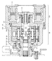
従来のインホイールモータ駆動装置として例えば特開2013−148198号公報(特許文献1)に記載されるものが知られている。特許文献1のインホイールモータ駆動装置は、電動車両の車輪内部に配置され、コンパクトで高い減速比が得られるサイクロイド減速機を備える。従来のインホイールモータ駆動装置を示す図7の縦断面図を参照して、電動モータ110のロータ111は軸受112によって回転自在に支持される。減速機120の入力軸121は軸受122によって回転自在に支持される。減速機120の出力回転を取り出す一対の環状板123は軸受124によってそれぞれ回転自在に支持される。   As a conventional in-wheel motor drive device, for example, a device described in JP 2013-148198 A (Patent Document 1) is known. The in-wheel motor drive apparatus of patent document 1 is arrange | positioned inside the wheel of an electric vehicle, and is provided with the cycloid reducer which is compact and can obtain a high reduction ratio. Referring to the longitudinal sectional view of FIG. 7 showing a conventional in-wheel motor drive device, the rotor 111 of the electric motor 110 is rotatably supported by a bearing 112. The input shaft 121 of the speed reducer 120 is rotatably supported by a bearing 122. A pair of annular plates 123 for extracting the output rotation of the speed reducer 120 are rotatably supported by bearings 124, respectively.

特開2013−148198号公報JP 2013-148198 A

しかし、上記従来のインホイールモータ駆動装置にあっては、さらに改善すべき点があることを本発明者は見いだした。つまり入力軸121には一対の偏心軸部125が偏心して設けられている。一対の偏心軸部125は偏心運動による遠心力で発生する振動を互いに打ち消すために周方向180°位相を変えて設けられているが、偏心軸部125は入力軸121の回転軸線を中心として高速で公転する場合に、加工誤差に基づく振動を完全に打ち消すことができず入力軸121には振動が生じる懸念があることを本発明者は見いだした。かかる入力軸121の振動は、軸受122と、環状板123と、軸受124と、内歯車126と、支持ピン127を順次経て、ケーシング129に伝達する。このためインホイールモータ駆動装置の外郭をなすケーシング129を含め、インホイールモータ駆動装置の各部材が振動する。そうすると、電動車両の振動が伝達されると乗り心地が損なわれたり、振動を原因として異音が発生したりする懸念がある。また図示はしなかったが、部品をインホイールモータ駆動装置にねじ止めするねじ止め部が緩んだりする懸念がある。   However, the present inventor has found that there is a point to be further improved in the conventional in-wheel motor driving device. That is, the input shaft 121 is provided with a pair of eccentric shaft portions 125 eccentrically. The pair of eccentric shafts 125 are provided with a 180 ° phase change in order to cancel vibrations generated by the centrifugal force due to the eccentric motion, but the eccentric shafts 125 are arranged at a high speed around the rotation axis of the input shaft 121. The present inventor has found that the vibration due to the processing error cannot be completely cancelled and the input shaft 121 may be vibrated when it is revolved. The vibration of the input shaft 121 is transmitted to the casing 129 through the bearing 122, the annular plate 123, the bearing 124, the internal gear 126, and the support pin 127 in order. For this reason, each member of an in-wheel motor drive device vibrates including the casing 129 which makes the outline of an in-wheel motor drive device. Then, there is a concern that when the vibration of the electric vehicle is transmitted, the ride comfort is impaired, or abnormal noise is generated due to the vibration. Although not shown, there is a concern that the screwing portion for screwing the component to the in-wheel motor drive device may be loosened.

特許文献1に採用されるサイクロイド減速機に限らず、インホイールモータ駆動装置においては、インホイールモータ駆動装置の内部で高速回転する回転要素の振動が、インホイールモータ駆動装置のケーシングに伝達することを極力低減することが望ましい。   In the in-wheel motor drive device as well as the cycloid reducer adopted in Patent Document 1, vibration of a rotating element that rotates at high speed inside the in-wheel motor drive device is transmitted to the casing of the in-wheel motor drive device. It is desirable to reduce as much as possible.

本発明は、上述の実情に鑑み、インホイールモータ駆動装置の内部の振動が、インホイールモータ駆動装置の外郭をなすケーシングに伝達することを低減することを目的とする。   In view of the above circumstances, an object of the present invention is to reduce transmission of internal vibrations of an in-wheel motor drive device to a casing that forms an outline of the in-wheel motor drive device.

この目的のため第1発明によるインホイールモータ駆動装置は、モータ側回転部材を駆動するモータ部と、モータ側回転部材の回転を減速して車輪側回転部材に出力する減速部とを備え、モータ側回転部材をケーシング側部材に回転自在に支持する軸受、および/または車輪側回転部材をケーシング側部材に回転自在に支持する軸受は、外輪および複数の転動体を含む転がり軸受であり、外輪とケーシング側部材との間には、高分子材料からなる緩衝部材が介在することを特徴とする。   For this purpose, the in-wheel motor drive device according to the first invention comprises a motor section for driving the motor side rotating member, and a speed reducing section for decelerating the rotation of the motor side rotating member and outputting it to the wheel side rotating member. The bearing that rotatably supports the side rotating member on the casing side member and / or the bearing that rotatably supports the wheel side rotating member on the casing side member is a rolling bearing including an outer ring and a plurality of rolling elements. A buffer member made of a polymer material is interposed between the casing side member and the casing side member.

また第2発明によるインホイールモータ駆動装置は、モータ側回転部材を駆動するモータ部と、モータ側回転部材の回転を減速して車輪側回転部材に出力する減速部とを備え、モータ側回転部材をケーシング側部材に回転自在に支持する軸受、および/または車輪側回転部材をケーシング側部材に回転自在に支持する軸受は、内輪および複数の転動体を含む転がり軸受であり、内輪と該内輪を貫通するモータ側回転部材および/または車輪側回転部材との間には、高分子材料からなる緩衝部材が介在することを特徴とする。   The in-wheel motor drive device according to the second invention includes a motor unit that drives the motor-side rotation member, and a reduction unit that decelerates the rotation of the motor-side rotation member and outputs it to the wheel-side rotation member. The bearing that rotatably supports the casing side member and / or the bearing that rotatably supports the wheel side rotating member on the casing side member is a rolling bearing including an inner ring and a plurality of rolling elements. A buffer member made of a polymer material is interposed between the penetrating motor-side rotating member and / or the wheel-side rotating member.

かかる第1および第2発明によれば、モータ側回転部材および車輪側回転部材といったインホイールモータ駆動装置内部の回転部材と、インホイールモータ駆動装置の外郭をなす非回転部材のケーシングと、回転部材をケーシングに支持する転がり軸受との支持関係において、回転部材とケーシングの間に高分子材料からなる緩衝部材が介在することから、緩衝部材が振動を吸収し回転部材の振動がケーシングに伝達することを低減することができる。   According to the first and second aspects of the present invention, the rotating member inside the in-wheel motor driving device such as the motor-side rotating member and the wheel-side rotating member, the casing of the non-rotating member that forms the outline of the in-wheel motor driving device, and the rotating member In the support relationship with the rolling bearing that supports the casing, since the buffer member made of a polymer material is interposed between the rotating member and the casing, the buffer member absorbs vibration and the vibration of the rotating member is transmitted to the casing. Can be reduced.

また第1および第2発明によれば軸受の外輪または内輪と、ケーシングまたは回転部材といった内外輪の取り付け先になる相手部材との間に、高分子材料からなる緩衝部材が介在することから、軸受の熱膨張率と相手部材との熱膨張率が異なる場合、緩衝部材が内/外輪と相手部材の熱膨張差を吸収するよう設計する。したがって温度変化に係わらず内/外輪と相手部材の嵌め合い状態、例えば接触面圧、を所定の範囲に保ち、クリープを防止することができる。   According to the first and second inventions, since the buffer member made of a polymer material is interposed between the outer ring or inner ring of the bearing and the counterpart member to which the inner and outer rings are attached, such as the casing or the rotating member, the bearing When the coefficient of thermal expansion differs from that of the mating member, the buffer member is designed to absorb the difference in thermal expansion between the inner / outer ring and the mating member. Therefore, regardless of the temperature change, the fitting state of the inner / outer ring and the mating member, for example, the contact surface pressure, can be kept within a predetermined range and creep can be prevented.

なお転がり軸受は、一例として回転部材とは別部材の内輪と、ケーシング側部材とは別部材の外輪の双方を有する。あるいは他の例として、内輪が別部材としてではなく回転部材に一体形成されていてもよい。あるいはさらに他の例として、外輪が別部材としてではなくケーシング側部材に一体形成されていてもよい。   As an example, the rolling bearing has both an inner ring that is a member different from the rotating member and an outer ring that is a member different from the casing side member. Alternatively, as another example, the inner ring may be integrally formed with the rotating member rather than as a separate member. Alternatively, as still another example, the outer ring may be integrally formed with the casing side member, not as a separate member.

ケーシング側部材は、インホイールモータ駆動装置の外郭をなすケーシングの他、ケーシングに附設される部材であってもよいし、非回転の固定部材であるか回転する部材であるかを問わず転がり軸受からみてケーシングに近い方の部材であればよい。   The casing-side member may be a member attached to the casing in addition to the casing that forms the outline of the in-wheel motor drive device, or a rolling bearing regardless of whether it is a non-rotating fixed member or a rotating member. Any member may be used as long as it is closer to the casing.

本発明の一実施形態として、モータ側回転部材はモータ部の一部であり該モータ部から回転を出力するモータ回転軸と、減速部の一部であり該減速部に回転を入力する減速部入力軸とを含み、緩衝部材はモータ回転軸をケーシング側部材に回転自在に支持する軸受に設けられる。他の実施形態として、緩衝部材は減速部入力軸をケーシング側部材に回転自在に支持する軸受に設けられる。   As one embodiment of the present invention, the motor-side rotating member is a part of the motor unit, and a motor rotating shaft that outputs rotation from the motor unit, and a speed reducing unit that is part of the speed reducing unit and inputs rotation to the speed reducing unit The buffer member is provided on a bearing that rotatably supports the motor rotation shaft on the casing side member. As another embodiment, the buffer member is provided in a bearing that rotatably supports the speed reducing portion input shaft on the casing side member.

高分子材料からなる緩衝部材の形状、寸法、および個数は特に限定されない。本発明の一実施形態として、緩衝部材は内輪の内周面または外輪の外周面に沿って延びる環状体である。かかる実施形態によれば、内輪または外輪の全周に亘って緩衝部材が介在することから、振動の伝達を効果的に低減することができる。環状体の軸方向幅寸法および径方向厚み寸法は特に限定されない。環状体は、例えば無端バンドのような帯状体である。環状体の軸方向幅寸法は、周方向位置に係わらず一定であるのが好ましい。また環状体の径方向厚み寸法も、周方向位置に係わらず一定であるのが好ましい。他の実施形態として、緩衝部材は周方向に間隔を空けて転がり軸受に設けられてもよい。   The shape, size, and number of the buffer members made of the polymer material are not particularly limited. As one embodiment of the present invention, the buffer member is an annular body extending along the inner peripheral surface of the inner ring or the outer peripheral surface of the outer ring. According to this embodiment, since the buffer member is provided over the entire circumference of the inner ring or the outer ring, transmission of vibration can be effectively reduced. The axial width dimension and the radial thickness dimension of the annular body are not particularly limited. The annular body is a strip-like body such as an endless band. It is preferable that the axial width dimension of the annular body is constant regardless of the circumferential position. The radial thickness of the annular body is also preferably constant regardless of the circumferential position. As another embodiment, the buffer member may be provided on the rolling bearing with an interval in the circumferential direction.

高分子材料からなる緩衝部材とは、要するに樹脂であり、緩衝部材に入力される振動を吸収・減衰する性能が高いほど良い。また緩衝部材は、軸受に用いられることから耐油性が高く、潤滑油に長期間晒されても劣化し難いことが望まれる。また緩衝部材は、インホイールモータ駆動装置の内部に設けられることから、耐熱性が高く、150℃の高温でも劣化しないことが望まれる。本発明の好ましい実施形態として、緩衝部材はフッ素系高分子材料またはアクリル系高分子材料を主成分とする弾性体である。かかる実施形態によれば、緩衝部材の耐油性および耐熱性を確保することができる。フッ素系高分子材料を用いる弾性体として例えば、フッ素ゴム、フロオロシリコーンゴム等が挙げられる。アクリル系高分子材料を主成分とする弾性体として例えば、アクリルゴム等が挙げられる。他の実施形態として緩衝部材は、他の種類の高分子材料から構成されてもよい。   The buffer member made of a polymer material is basically a resin, and the higher the performance of absorbing and attenuating vibrations input to the buffer member, the better. Further, since the buffer member is used for a bearing, it is desired that the buffer member has high oil resistance and is hardly deteriorated even if it is exposed to lubricating oil for a long time. Further, since the buffer member is provided inside the in-wheel motor drive device, it is desired that the buffer member has high heat resistance and does not deteriorate even at a high temperature of 150 ° C. As a preferred embodiment of the present invention, the buffer member is an elastic body mainly composed of a fluorine polymer material or an acrylic polymer material. According to this embodiment, the oil resistance and heat resistance of the buffer member can be ensured. Examples of the elastic body using a fluorine-based polymer material include fluorine rubber and fluorosilicone rubber. Examples of the elastic body mainly composed of an acrylic polymer material include acrylic rubber. In another embodiment, the buffer member may be made of other types of polymer materials.

本発明のケーシング側部材は、非回転の固定部材であってもよいし、回転する部材であってもよい。本発明の一実施形態として、モータ側回転部材は車輪側回転部材に同軸配置され、車輪側回転部材の端部にはモータ側回転部材の端部を受け入れる円形凹部が形成される。そしてモータ側回転部材をケーシング側部材に回転自在に支持する軸受は、円形凹部の内周面とモータ側回転部材の外周面の間に画成される環状空間に設置され、緩衝部材を伴う。   The casing-side member of the present invention may be a non-rotating fixed member or a rotating member. As one embodiment of the present invention, the motor-side rotating member is coaxially arranged with the wheel-side rotating member, and a circular recess that receives the end of the motor-side rotating member is formed at the end of the wheel-side rotating member. The bearing that rotatably supports the motor-side rotating member on the casing-side member is installed in an annular space defined between the inner peripheral surface of the circular recess and the outer peripheral surface of the motor-side rotating member, and includes a buffer member.

本発明の一実施形態として、減速部はモータ側回転部材に偏心して設けられた一対の偏心部と、偏心部に相対回転可能に保持されモータ側回転部材の回転に伴って該モータ側回転部材の軸線を中心とする公転運動を行う一対の公転部材と、公転部材の外周に係合して公転部材の自転運動を生じさせる外周係合部材と、公転部材の自転運動をモータ側回転部材の軸線を中心とする回転運動に変換して車輪側回転部材へ出力する運動変換機構とを有する。かかる実施形態によれば、サイクロイド減速機の内部から発生する振動を低減することができる。他の実施形態として、減速部は他の歯車組であってもよい。   As one embodiment of the present invention, the speed reducing portion is eccentrically provided on the motor-side rotating member, and the motor-side rotating member is held by the rotation of the motor-side rotating member that is held by the eccentric portion so as to be relatively rotatable. A pair of revolving members that revolve around the axis of the outer periphery, an outer peripheral engagement member that engages with the outer periphery of the revolving member to cause the revolving motion of the revolving member, and the rotational movement of the revolving member of the motor side rotating member. And a motion conversion mechanism that converts the rotational motion about the axis to the wheel-side rotating member. According to this embodiment, vibration generated from the inside of the cycloid reduction gear can be reduced. As another embodiment, the reduction gear may be another gear set.

このように本発明によれば、インホイールモータ駆動装置において、減速部内部の回転部材から発生する振動を低減することができる。したがってインホイールモータ駆動装置を搭載する電気自動車あるいはハイブリッド車両において乗り心地性能が改善される。また振動を原因とする不具合が生じることがなく、インホイールモータ駆動装置の耐久性が向上する。   As described above, according to the present invention, in the in-wheel motor drive device, it is possible to reduce the vibration generated from the rotating member inside the speed reducing portion. Therefore, riding comfort performance is improved in an electric vehicle or a hybrid vehicle equipped with an in-wheel motor drive device. Further, there is no problem caused by vibration, and the durability of the in-wheel motor drive device is improved.

本発明の一実施形態になるインホイールモータ駆動装置を示す縦断面図である。It is a longitudinal cross-sectional view which shows the in-wheel motor drive device which becomes one Embodiment of this invention. 図1のII−IIにおける横断面図である。It is a cross-sectional view in II-II of FIG. 図1中の減速部を拡大して示す縦断面図である。It is a longitudinal cross-sectional view which expands and shows the deceleration part in FIG. 緩衝部材を取り付けた転がり軸受を取り出して示す縦断面図である。It is a longitudinal cross-sectional view which takes out and shows the rolling bearing which attached the buffer member. 本発明の他の実施形態を示す縦断面図であり、インホイールモータ駆動装置の減速部を拡大して示す。It is a longitudinal cross-sectional view which shows other embodiment of this invention, and expands and shows the deceleration part of an in-wheel motor drive device. 本発明のさらに他の実施形態を示す縦断面図であり、インホイールモータ駆動装置のモータ部を拡大して示す。It is a longitudinal cross-sectional view which shows other embodiment of this invention, and expands and shows the motor part of an in-wheel motor drive device. 従来のインホイールモータ駆動装置を示す縦断面図である。It is a longitudinal cross-sectional view which shows the conventional in-wheel motor drive device.

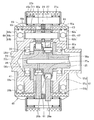
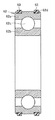
以下、本発明の実施の形態を、図面に基づき詳細に説明する。図1は、本発明の一実施形態になるインホイールモータ駆動装置を示す縦断面図である。図2は図1のII−IIにおける横断面図である。図3は、図1中の減速部を拡大して示す縦断面図である。図4は、図3中の転がり軸受を取り出して示す縦断面図である。インホイールモータ駆動装置21は、駆動力を発生させるモータ部Aと、モータ部Aの回転を減速して出力する減速部Bと、減速部Bからの出力を駆動輪に伝える車輪ハブ軸受部Cとを備える。   Hereinafter, embodiments of the present invention will be described in detail with reference to the drawings. FIG. 1 is a longitudinal sectional view showing an in-wheel motor drive device according to an embodiment of the present invention. 2 is a cross-sectional view taken along the line II-II in FIG. FIG. 3 is an enlarged longitudinal sectional view showing the speed reducing portion in FIG. 4 is a longitudinal sectional view showing the rolling bearing in FIG. The in-wheel motor drive device 21 includes a motor unit A that generates a driving force, a deceleration unit B that decelerates and outputs the rotation of the motor unit A, and a wheel hub bearing unit C that transmits the output from the deceleration unit B to driving wheels. With.

モータ部Aはモータ部の外郭を形成するモータケーシング22a、ポンプケーシング22p、およびモータカバー22tを有し、減速部Bは減速部の外郭を形成する減速部ケーシング22bを有する。これらモータケーシング22a、ポンプケーシング22p、モータカバー22t、および減速部ケーシング22bは、ボルト等により、あるいは一体形成により、相互に結合して1個のケーシング22を構成する。そしてケーシング22には、車輪ハブ軸受部Cの外輪部材33aが取付固定される。インホイールモータ駆動装置21は、例えば電気自動車のホイールハウジング内に取り付けられる。この電気自動車は乗用自動車であり、一般的なエンジン自動車と同様に公道を走行可能である。   The motor part A has a motor casing 22a that forms an outer shell of the motor part, a pump casing 22p, and a motor cover 22t, and the speed reducing part B has a speed reducing part casing 22b that forms the outer shell of the speed reducing part. The motor casing 22a, the pump casing 22p, the motor cover 22t, and the speed reducer casing 22b are coupled to each other by a bolt or the like or integrally formed to constitute one casing 22. Then, the outer ring member 33 a of the wheel hub bearing portion C is attached and fixed to the casing 22. The in-wheel motor drive device 21 is attached, for example, in a wheel housing of an electric vehicle. This electric vehicle is a passenger car and can travel on public roads like a general engine car.

モータ部Aは、円筒形状のモータケーシング22a内周に固定されるステータ23と、ステータ23の内側に径方向に開いた隙間を介して対面する位置に配置されるロータ24と、ロータ24の内側に連結固定されてロータ24と一体回転するモータ回転軸35とを備えるラジアルギャップモータである。あるいは図示はしなかったが、モータ部Aはアキシャルギャップモータであってもよい。   The motor part A includes a stator 23 fixed to the inner periphery of a cylindrical motor casing 22a, a rotor 24 disposed at a position facing the inner side of the stator 23 via a gap opened in the radial direction, and an inner side of the rotor 24. A radial gap motor including a motor rotating shaft 35 that is connected and fixed to the rotor 24 and rotates integrally with the rotor 24. Alternatively, although not shown, the motor part A may be an axial gap motor.

モータケーシング22aは、モータ回転軸35の軸線Oを中心とし、この軸線方向に延びる。ケーシング22の一部であるポンプケーシング22pは、略円板形状の隔壁であって、モータ部Aの軸線O方向一方端で減速部Bとの境界を形成するとともに、転がり軸受37を介してモータ回転軸35の一方端部を回転自在に支持する。さらにポンプケーシング22pは、オイルポンプ51を備える。ケーシング22の一部であるモータカバー22tは、略円板形状であって、モータ部Aの軸線O方向他方端でモータ部Aの端面を形成するとともに、転がり軸受36を介してモータ回転軸35の他方端部を回転自在に支持する。モータカバー22tはモータ部Aの端部であるとともに、インホイールモータ駆動装置21の端部でもある。   The motor casing 22a extends about the axis O of the motor rotation shaft 35 in the axial direction. The pump casing 22p which is a part of the casing 22 is a substantially disc-shaped partition wall, which forms a boundary with the speed reduction part B at one end in the axis O direction of the motor part A, and a motor via a rolling bearing 37. One end of the rotating shaft 35 is rotatably supported. Further, the pump casing 22p includes an oil pump 51. The motor cover 22t which is a part of the casing 22 has a substantially disc shape, and forms an end surface of the motor part A at the other end in the axis O direction of the motor part A, and a motor rotating shaft 35 via a rolling bearing 36. The other end of this is rotatably supported. The motor cover 22t is an end portion of the motor part A and also an end portion of the in-wheel motor drive device 21.

モータ回転軸35の一端は、減速部Bの内部に回転自在に設けられた減速部入力軸25と結合する。この結合はセレーション嵌合であり、管状に形成されたモータ回転軸35の端部開口に、先細に形成された減速部入力軸25が挿入固定される。   One end of the motor rotating shaft 35 is coupled to a speed reducing portion input shaft 25 that is rotatably provided inside the speed reducing portion B. This coupling is serration fitting, and the tapered speed reduction portion input shaft 25 is inserted and fixed in the end opening of the motor rotation shaft 35 formed in a tubular shape.

減速部Bは、サイクロイド減速機であって、モータ部Aの軸線O方向一方側に同軸配置され、円筒形状の減速部ケーシング22bと、減速部ケーシング22bに取り付け固定される外ピン保持部45と、軸線Oに沿って延びる減速部入力軸25と、減速部入力軸25に形成された一対の偏心部25a,25bと、それぞれの偏心部25a,25bに回転自在に保持される公転部材としての一対の曲線板26a,26bと、曲線板26a,26bの外周部に係合する外周係合部材としての複数の外ピン27と、軸線Oに沿って延びる減速部出力軸28と、減速部出力軸28と結合し、曲線板26a,26bの自転運動を取り出す内側係合部材としての内ピン31と、一対の曲線板26a,26b間の隙間に取り付けられてこれら曲線板26a,26bの端面に当接して曲線板の傾きを防止するセンターカラー29と、補強部材61とを有する。   The speed reduction part B is a cycloid speed reducer, and is coaxially arranged on one side in the axis O direction of the motor part A, and has a cylindrical speed reduction part casing 22b and an outer pin holding part 45 attached and fixed to the speed reduction part casing 22b. As a revolving member that is rotatably held by the decelerating portion input shaft 25 extending along the axis O, a pair of eccentric portions 25a and 25b formed on the decelerating portion input shaft 25, and the eccentric portions 25a and 25b. A pair of curved plates 26a, 26b, a plurality of outer pins 27 as outer peripheral engagement members that engage with the outer peripheral portions of the curved plates 26a, 26b, a speed reduction portion output shaft 28 extending along the axis O, and a speed reduction portion output The curved plate 26a, 26b is attached to the inner pin 31 as an inner engagement member that couples with the shaft 28 and extracts the rotational movement of the curved plates 26a, 26b, and the curved plate 26a, 26b. Contact with the end face of 6b the center collar 29 to prevent the inclination of the curved plates, and a reinforcing member 61.

減速部入力軸25は、モータ回転軸35の軸線Oに沿って延び、その両端部のうちモータ部Aに近い側にある減速部入力軸25の端部がモータ回転軸35の一端と結合する。モータ部Aから遠い側にある減速部入力軸25の端部は、転がり軸受39を介して、後述する減速部出力軸28の端部に回転自在に支持される。減速部入力軸25の外周には、一対の偏心部25a,25bが軸線Oから偏心して形成される。減速部入力軸25は、偏心部25a,25bよりもモータ部Aに近い側で、転がり軸受38によって回転自在に支持される。   The speed reduction unit input shaft 25 extends along the axis O of the motor rotation shaft 35, and the end of the speed reduction unit input shaft 25 on the side closer to the motor unit A of both ends thereof is coupled to one end of the motor rotation shaft 35. . The end of the speed reduction part input shaft 25 on the side far from the motor part A is rotatably supported by the end of a speed reduction part output shaft 28 described later via a rolling bearing 39. A pair of eccentric portions 25 a and 25 b are formed eccentrically from the axis O on the outer periphery of the deceleration portion input shaft 25. The speed reduction part input shaft 25 is rotatably supported by the rolling bearing 38 on the side closer to the motor part A than the eccentric parts 25a and 25b.

2個で一対の偏心部25a,25bは、円板形状であり、軸線O方向に離隔して配置され、偏心運動による遠心力で発生する振動を互いに打ち消し合うために、周方向180°位相を変えて設けられている。モータ回転軸35および減速部入力軸25は、モータ部Aの駆動力を減速部Bに伝達するモータ側回転部材を構成する。   The two pairs of eccentric parts 25a and 25b have a disk shape and are spaced apart from each other in the direction of the axis O. In order to cancel vibrations generated by the centrifugal force due to the eccentric motion, the circumferential direction has a 180 ° phase. It is provided by changing. The motor rotation shaft 35 and the speed reduction part input shaft 25 constitute a motor side rotation member that transmits the driving force of the motor part A to the speed reduction part B.

図2を参照して、曲線板26bは円板形状であり、その外周部を波形に形成される。具体的には曲線板26bの外周部は、エピトロコイド等のトロコイド系曲線で構成されて径方向に窪んだ複数の曲線凹部であり、外ピン27と噛合する。また曲線板26bは、一方側端面から他方側端面に貫通する複数の貫通孔30a,30bを有する。貫通孔30aは、曲線板26bの自転軸心Xを中心とする円周上に等間隔に複数個設けられており、内ピン31を受入れる。また、貫通孔30bは、曲線板26bの自転軸心Xに設けられており、曲線板26bの内周になる。曲線板26bは、偏心部25bの外周に相対回転可能に取り付けられる。内ピン31は、針状ころ軸受を含み、内ピン本体31aと、複数の針状ころ31bと、軸受外輪31cを有する。内ピン本体31aは軸受外輪31cを貫通し、針状ころ31bは内ピン本体31aおよび軸受外輪31c間の環状空間に配置される。軸受外輪31cの外周面は、貫通孔31aの孔壁面と転がり接触する。   Referring to FIG. 2, curved plate 26b has a disc shape, and its outer peripheral portion is formed in a waveform. Specifically, the outer peripheral portion of the curved plate 26 b is a plurality of curved concave portions formed of a trochoidal curve such as an epitrochoid and recessed in the radial direction, and meshes with the outer pin 27. The curved plate 26b has a plurality of through holes 30a and 30b penetrating from one end face to the other end face. A plurality of through holes 30a are provided at equal intervals on the circumference centering on the rotation axis X of the curved plate 26b, and receive the inner pins 31. Moreover, the through-hole 30b is provided in the autorotation axis X of the curved plate 26b, and becomes an inner periphery of the curved plate 26b. The curved plate 26b is attached to the outer periphery of the eccentric portion 25b so as to be relatively rotatable. The inner pin 31 includes a needle roller bearing, and includes an inner pin main body 31a, a plurality of needle rollers 31b, and a bearing outer ring 31c. The inner pin main body 31a passes through the bearing outer ring 31c, and the needle rollers 31b are disposed in an annular space between the inner pin main body 31a and the bearing outer ring 31c. The outer peripheral surface of the bearing outer ring 31c is in rolling contact with the hole wall surface of the through hole 31a.

曲線板26bは、転がり軸受41によって偏心部25bに対して回転自在に支持されている。理解を容易にするため図2では転がり軸受41の周方向一部を破断して示す。この転がり軸受41は、外径面に内側軌道面42aを有する環状の内輪部材42と、内側軌道面42aと外側軌道面になる貫通孔30bの孔壁面との間に配置される複数のころ44と、周方向で隣り合うころ44の間隔を保持する保持器(図示省略)とを備える円筒ころ軸受である。あるいは深溝玉軸受であってもよい。内輪部材42の内径面は偏心部25bの外径面に嵌合する。内輪部材42は内側軌道面42aに位置し径方向に貫通する孔43および内側軌道面42aを挟んで向かい合う一対の鍔部をさらに有する。孔43は、偏心部25b内部を軸線O直角方向に延びる分岐油路58bと接続する。曲線板26aについても同様である。   The curved plate 26b is rotatably supported by the rolling bearing 41 with respect to the eccentric portion 25b. In order to facilitate understanding, a part of the rolling bearing 41 in the circumferential direction is shown in FIG. The rolling bearing 41 includes a plurality of rollers 44 disposed between an annular inner ring member 42 having an inner raceway surface 42a on the outer diameter surface and a hole wall surface of the through-hole 30b serving as the outer raceway surface. And a cylindrical roller bearing provided with a cage (not shown) that holds the interval between the rollers 44 adjacent in the circumferential direction. Alternatively, it may be a deep groove ball bearing. The inner diameter surface of the inner ring member 42 is fitted to the outer diameter surface of the eccentric portion 25b. The inner ring member 42 further includes a hole 43 that is located on the inner raceway surface 42a and penetrates in the radial direction and a pair of flanges that face each other across the inner raceway surface 42a. The hole 43 connects the inside of the eccentric portion 25b to a branch oil passage 58b extending in the direction perpendicular to the axis O. The same applies to the curved plate 26a.

外ピン27は、モータ側回転部材の軸線Oを中心とする円周軌道上に等間隔に複数設けられ(図2参照)、軸線Oと平行に延びる。そして、2個で一対の曲線板26a,26bが軸線Oを中心として公転運動すると、曲線板26a,26b外周の曲線凹部と外ピン27とが係合して、曲線板26a,26bに自転運動を生じさせる。   A plurality of outer pins 27 are provided at equal intervals on a circumferential track centered on the axis O of the motor-side rotating member (see FIG. 2), and extend parallel to the axis O. When the two pair of curved plates 26a, 26b revolve around the axis O, the curved concave portions on the outer periphery of the curved plates 26a, 26b engage with the outer pin 27, and the curved plates 26a, 26b rotate. Give rise to

なお、減速部ケーシング22b内部に配設された外ピン27は、減速部ケーシング22bの内壁面に直接連結固定されていてもよいが、好ましくは減速部ケーシング22bの内壁面に取付固定されている外ピン保持部45に保持されている。より具体的には、図3に示すように、外ピン27の軸線方向両端部を外ピン保持部45に取り付けられた針状ころ軸受27a(転がり軸受)によって回転自在に支持されている。このように、外ピン27を転がり軸受を介して外ピン保持部45に転がり回転自在に取り付けることにより、曲線板26a,26bとの係合による接触抵抗を低減することができる。詳しくは後述するが外ピン保持部45の他、減速部出力軸28、補強部材61、およびケーシング22を、ケーシング側部材と総称する場合がある。   The outer pin 27 disposed inside the speed reduction unit casing 22b may be directly connected and fixed to the inner wall surface of the speed reduction unit casing 22b, but is preferably attached and fixed to the inner wall surface of the speed reduction unit casing 22b. It is held by the outer pin holding part 45. More specifically, as shown in FIG. 3, both axial ends of the outer pin 27 are rotatably supported by needle roller bearings 27 a (rolling bearings) attached to the outer pin holding portion 45. In this way, by attaching the outer pin 27 to the outer pin holding portion 45 via the rolling bearing so as to be rotatable and rotatable, the contact resistance due to the engagement with the curved plates 26a and 26b can be reduced. Although described in detail later, in addition to the outer pin holding portion 45, the speed reduction portion output shaft 28, the reinforcing member 61, and the casing 22 may be collectively referred to as a casing side member.

上述した全ての実施形態では減速部ケーシング22bに取付固定される円筒形状の外ピン保持部45が減速部ケーシング22bの内壁面から離隔して設けられているが、これに限定されない。図示はしなかったが、変形例として外ピン保持部45の外壁面が減速部ケーシング22bの内壁面に密着してもよい。あるいは図示はしなかったが、外ピン保持部45は減速部ケーシング22bに一体形成されていてもよい。   In all the embodiments described above, the cylindrical outer pin holding part 45 attached and fixed to the speed reduction part casing 22b is provided separately from the inner wall surface of the speed reduction part casing 22b, but is not limited thereto. Although not shown, as an alternative, the outer wall surface of the outer pin holding portion 45 may be in close contact with the inner wall surface of the speed reduction portion casing 22b. Or although not illustrated, the outer pin holding | maintenance part 45 may be integrally formed in the deceleration part casing 22b.

図3を参照して、外ピン保持部45は円筒形状であり、外ピン保持部45の軸方向中央部45cが両端側の軸方向端部45a,45bよりも大径にされる。そして小径の軸方向端部45a,45bと大径の軸方向中央部45cとの間の環状空間に、外ピン27が配置される。また外ピン保持部45は、軸方向端部45a,45bよりも内径側に曲線板26a,26b、減速部出力軸28の端部、内ピン31、偏心部25a,25b、減速部入力軸25の端部を収容する。減速部ケーシング22bからみて外ピン保持部45はフローティング状態にされ、外ピン保持部45の外周面は減速部ケーシング22bの内壁面から離隔する。ただし外ピン保持部45は、ボルトあるいはキーといった固定手段によって減速部ケーシング22bに相対回転不能に取付固定される。このように外ピン保持部45は、非回転の固定部材であり、減速部出力軸28からみて減速部ケーシング22b側にあるケーシング側部材である。インホイールモータ駆動装置21の軽量化の観点から、減速部ケーシング22bを含めて、ケーシング22はアルミ合金やマグネシウム合金等の軽金属で形成する。一方、高い強度が求められる外ピン保持部45は、炭素鋼で形成するのが望ましい。2枚の曲線板26a,26b間には環状のセンターカラー29が配置される。センターカラー29は曲線板26a,26bが軸線Oに対して傾くことを防止する。   Referring to FIG. 3, outer pin holding portion 45 has a cylindrical shape, and axial center portion 45c of outer pin holding portion 45 has a larger diameter than axial end portions 45a and 45b on both ends. The outer pin 27 is disposed in an annular space between the small-diameter axial ends 45a and 45b and the large-diameter axial central portion 45c. Further, the outer pin holding portion 45 has curved plates 26a, 26b, ends of the speed reduction portion output shaft 28, inner pins 31, eccentric portions 25a, 25b, speed reduction portion input shaft 25 on the inner diameter side of the axial ends 45a, 45b. The end of the is housed. The outer pin holding portion 45 is brought into a floating state when viewed from the speed reduction portion casing 22b, and the outer peripheral surface of the outer pin holding portion 45 is separated from the inner wall surface of the speed reduction portion casing 22b. However, the outer pin holding portion 45 is attached and fixed to the speed reduction portion casing 22b by a fixing means such as a bolt or a key so as not to be relatively rotatable. As described above, the outer pin holding portion 45 is a non-rotating fixed member and is a casing side member on the speed reduction portion casing 22b side as viewed from the speed reduction portion output shaft 28. From the viewpoint of reducing the weight of the in-wheel motor drive device 21, the casing 22 including the speed reduction portion casing 22b is formed of a light metal such as an aluminum alloy or a magnesium alloy. On the other hand, it is desirable to form the outer pin holding part 45, which requires high strength, from carbon steel. An annular center collar 29 is disposed between the two curved plates 26a and 26b. The center collar 29 prevents the curved plates 26a and 26b from being inclined with respect to the axis O.

減速部出力軸28は、モータ部A側の端部に大径フランジ部28bを、車輪ハブ軸受部C側に軸部28dを有する。大径フランジ部28bと軸部28dとの接続箇所には小径フランジ部28cが形成される。大径フランジ部28bの中心には減速部入力軸25の一端を受け入れる円形凹部34が形成され、円形凹部34の内周面に転がり軸受39が配置される。   The speed reduction part output shaft 28 has a large-diameter flange part 28b at the end part on the motor part A side and a shaft part 28d on the wheel hub bearing part C side. A small-diameter flange portion 28c is formed at a connection portion between the large-diameter flange portion 28b and the shaft portion 28d. A circular recess 34 is formed in the center of the large-diameter flange portion 28b to receive one end of the speed reducer input shaft 25. A rolling bearing 39 is disposed on the inner peripheral surface of the circular recess 34.

大径フランジ部28bの外縁部には、減速部出力軸28の軸線Oを中心とする円周上の等間隔に内ピン31の一端部を固定する穴が形成されている。軸部28dの外周面には、車輪ハブ軸受部Cの車輪ハブ32が連結固定されている(図1参照)。   In the outer edge portion of the large diameter flange portion 28b, holes for fixing one end portion of the inner pin 31 are formed at equal intervals on the circumference around the axis O of the speed reduction portion output shaft 28. The wheel hub 32 of the wheel hub bearing portion C is connected and fixed to the outer peripheral surface of the shaft portion 28d (see FIG. 1).

図3に示すように、大径フランジ部28bから離れた側にある内ピン31の他端部には、補強部材61が設けられている。補強部材61は、減速部B内部で複数の内ピン31先端と結合固定するフランジ形状の大径円板部61bと、大径円板部61bに隣接して同軸に形成され、大径円板部61bよりも小径の小径円板部61cと、小径円板部61cの内周縁からモータ部Aへ延びるさらに小径の円筒部61dとを含む。円筒部61dは軸線Oに沿って延びる形状であるのに対し、大径円板部61bおよび小径円板部61cは、互いに一体形成されて軸線O直角方向に広がる円板部である。   As shown in FIG. 3, a reinforcing member 61 is provided at the other end of the inner pin 31 on the side away from the large-diameter flange portion 28b. The reinforcing member 61 is a flange-shaped large-diameter disc portion 61b that is coupled and fixed to the tips of the plurality of inner pins 31 inside the speed reduction portion B, and is coaxially formed adjacent to the large-diameter disc portion 61b. A small-diameter disk part 61c having a smaller diameter than the part 61b and a smaller-diameter cylindrical part 61d extending from the inner peripheral edge of the small-diameter disk part 61c to the motor part A are included. The cylindrical portion 61d has a shape extending along the axis O, whereas the large-diameter disc portion 61b and the small-diameter disc portion 61c are disc portions that are integrally formed and spread in the direction perpendicular to the axis O.

2枚の曲線板26a、26bから一部の内ピン31に負荷される荷重は補強部材61の大径円板部61bおよび減速部出力軸28の大径フランジ部28bを介して全ての内ピン31によって支持されるため、内ピン31に作用する応力を低減させ耐久性を向上させることができる。円筒部61dの先端は、オイルポンプ51に差し込まれて、オイルポンプ51を駆動する(図1参照)。小径円板部61cの内周面には転がり軸受38が配置され、転がり軸受38は減速部入力軸25を回転自在に支持する。   The load applied to a part of the inner pins 31 from the two curved plates 26a, 26b is applied to all the inner pins via the large-diameter disk portion 61b of the reinforcing member 61 and the large-diameter flange portion 28b of the reduction portion output shaft 28. Since it is supported by 31, the stress which acts on the inner pin 31 can be reduced and durability can be improved. The tip of the cylindrical portion 61d is inserted into the oil pump 51 to drive the oil pump 51 (see FIG. 1). A rolling bearing 38 is disposed on the inner peripheral surface of the small-diameter disc portion 61c, and the rolling bearing 38 supports the speed reduction portion input shaft 25 in a freely rotatable manner.

補強部材61は、内ピン31を介して減速部出力軸28と連結することから、減速部出力軸28と一体に回転する。減速部出力軸28、補強部材61、および車輪ハブ32は、図1に示すように、減速部Bの駆動力を駆動輪(ボルト32cと連結する図示しない駆動輪)に伝達する車輪側回転部材を構成する。   Since the reinforcing member 61 is connected to the speed reducing unit output shaft 28 via the inner pin 31, the reinforcing member 61 rotates integrally with the speed reducing unit output shaft 28. As shown in FIG. 1, the speed reducer output shaft 28, the reinforcing member 61, and the wheel hub 32 are wheel-side rotating members that transmit the driving force of the speed reducer B to drive wheels (drive wheels (not shown) connected to the bolts 32 c). Configure.

モータ回転軸35とセレーション嵌合する減速部入力軸25の端部を除き、減速部入力軸25の大部分は、環状の補強部材61から減速部出力軸28の小径フランジ部28cまでの軸線方向位置と一致する。そして減速部入力軸25は、補強部材61の内部および円形凹部34に配置されて、一方端側で転がり軸受39を介して減速部出力軸28に回転自在に支持され、他方端側で転がり軸受38を介して補強部材61に回転自在に支持される。   Except for the end of the speed reducer input shaft 25 that is serrated to the motor rotation shaft 35, most of the speed reducer input shaft 25 is in the axial direction from the annular reinforcing member 61 to the small-diameter flange portion 28c of the speed reducer output shaft 28. Match the position. The speed reducer input shaft 25 is disposed inside the reinforcing member 61 and in the circular recess 34, and is rotatably supported by the speed reducer output shaft 28 via the rolling bearing 39 on one end side, and the rolling bearing on the other end side. It is rotatably supported by the reinforcing member 61 via 38.

外ピン保持部45の両端部には金属製の転がり軸受62,64が配置される。転がり軸受62,64は車輪側回転部材を回転自在に支持する。転がり軸受62はモータ部Aに近い側に配置され、転がり軸受64は車輪ハブ軸受部Cに近い側に配置される。   Metal rolling bearings 62 and 64 are disposed at both ends of the outer pin holding portion 45. The rolling bearings 62 and 64 rotatably support the wheel side rotating member. The rolling bearing 62 is disposed on the side close to the motor part A, and the rolling bearing 64 is disposed on the side close to the wheel hub bearing part C.

図3に示すように、転がり軸受62の外輪62aは外ピン保持部45における軸方向端部45aの内周面に相対回転不能に取り付けられ、転がり軸受62の内輪62bは補強部材61の小径円板部61cの外周面に相対回転不能に取り付けられる。複数の転動体62cは外輪62aおよび内輪62b間の環状空間に配置される。複数の転動体62cは図示しない保持器によって円周方向等間隔に保持されている。大径円板部61bの外周面および小径円板部61cの外周面は環状段差を構成する。そして転がり軸受62は、これら大径円板部61bと小径円板部61cの環状段差に収納され、内ピン31と同じ径方向位置に配置される。外輪62aおよび外ピン保持部45間には緩衝部材63が介在する。緩衝部材63は外輪62aの外周面に沿って設けられる環状体である。本実施形態では2個の緩衝部材63が軸線O方向に間隔を空けて設けられる。   As shown in FIG. 3, the outer ring 62 a of the rolling bearing 62 is attached to the inner peripheral surface of the axial end portion 45 a of the outer pin holding portion 45 so as not to be relatively rotatable, and the inner ring 62 b of the rolling bearing 62 is a small-diameter circle of the reinforcing member 61. It is attached to the outer peripheral surface of the plate part 61c so as not to be relatively rotatable. The plurality of rolling elements 62c are arranged in an annular space between the outer ring 62a and the inner ring 62b. The plurality of rolling elements 62c are held at equal intervals in the circumferential direction by a holder (not shown). The outer peripheral surface of the large-diameter disc portion 61b and the outer peripheral surface of the small-diameter disc portion 61c constitute an annular step. The rolling bearing 62 is housed in an annular step between the large-diameter disk portion 61b and the small-diameter disk portion 61c, and is disposed at the same radial position as the inner pin 31. A buffer member 63 is interposed between the outer ring 62 a and the outer pin holding portion 45. The buffer member 63 is an annular body provided along the outer peripheral surface of the outer ring 62a. In the present embodiment, two buffer members 63 are provided with an interval in the direction of the axis O.

転がり軸受64の外輪64aは外ピン保持部45における軸方向端部45bの内周面に相対回転不能に取り付けられ、転がり軸受64の内輪64bは減速部出力軸28の小径フランジ部28cの外周面に相対回転不能に取り付けられる。複数の転動体64cは、外輪64aおよび内輪64b間の環状空間に配置される。複数の転動体62cは図示しない保持器によって円周方向等間隔に保持されている。大径フランジ部28bの外周面および小径フランジ部28cの外周面は環状段差を構成する。そして転がり軸受64は、これら大径フランジ部28bと小径フランジ部28cの環状段差に収納され、内ピン31と同じ径方向位置に配置される。外輪64aおよび外ピン保持部45間には緩衝部材65が介在する。2個の緩衝部材65は外輪64aの外周面に沿って設けられる環状体である。   The outer ring 64a of the rolling bearing 64 is attached to the inner peripheral surface of the axial end portion 45b of the outer pin holding portion 45 so as not to be relatively rotatable, and the inner ring 64b of the rolling bearing 64 is an outer peripheral surface of the small-diameter flange portion 28c of the speed reduction unit output shaft 28. It is attached so that relative rotation is impossible. The plurality of rolling elements 64c are arranged in an annular space between the outer ring 64a and the inner ring 64b. The plurality of rolling elements 62c are held at equal intervals in the circumferential direction by a holder (not shown). The outer peripheral surface of the large-diameter flange portion 28b and the outer peripheral surface of the small-diameter flange portion 28c constitute an annular step. The rolling bearing 64 is housed in an annular step between the large-diameter flange portion 28 b and the small-diameter flange portion 28 c and is disposed at the same radial position as the inner pin 31. A buffer member 65 is interposed between the outer ring 64 a and the outer pin holding portion 45. The two buffer members 65 are annular bodies provided along the outer peripheral surface of the outer ring 64a.

転がり軸受62,64は同様の構成を有し、緩衝部材63,65は同様の構成を有するので、緩衝部材63,65を代表して緩衝部材63を説明する。図4は緩衝部材63を取付けた転がり軸受62を取り出して示す縦断面図である。外輪62aの外周面には環状溝62dが複数本形成される。かかる環状溝62dには、樹脂バンドになる環状の緩衝部材63が嵌合する。外輪62aが相手材(軸方向端部45a)から取り外された状態で、緩衝部材63は軸方向端部45aから圧縮力を受けることなく、環状溝62dから盛り上がっている。これに対し外輪62aを軸方向端部45aに取り付けると、緩衝部材63は軸方向端部45aの内周面から圧縮力を受けて弾性変形し、環状溝62dの内部に収まる。   Since the rolling bearings 62 and 64 have the same configuration and the buffer members 63 and 65 have the same configuration, the buffer member 63 will be described as a representative of the buffer members 63 and 65. FIG. 4 is a longitudinal sectional view showing the rolling bearing 62 with the buffer member 63 attached. A plurality of annular grooves 62d are formed on the outer peripheral surface of the outer ring 62a. An annular buffer member 63 serving as a resin band is fitted into the annular groove 62d. In a state where the outer ring 62a is removed from the counterpart material (axial end 45a), the buffer member 63 rises from the annular groove 62d without receiving a compressive force from the axial end 45a. On the other hand, when the outer ring 62a is attached to the axial end portion 45a, the buffer member 63 is elastically deformed by receiving a compressive force from the inner peripheral surface of the axial end portion 45a, and fits inside the annular groove 62d.

なお図3を参照して、外ピン保持部45における軸方向端部45aの内周面には環状溝が形成されず、円筒面のままである。あるいは図示はしなかったが、変形例として軸方向端部45aの内周面に環状溝を設け、外輪62aの外周面を円筒面にしてもよい。   Referring to FIG. 3, an annular groove is not formed on the inner peripheral surface of the axial end portion 45 a of the outer pin holding portion 45, and it remains a cylindrical surface. Alternatively, although not illustrated, as a modification, an annular groove may be provided on the inner peripheral surface of the axial end portion 45a, and the outer peripheral surface of the outer ring 62a may be a cylindrical surface.

軸方向に計測される緩衝部材63の幅寸法は、荷重を掛けない自然状態で、1.0〜5.0[mm]に含まれる所定値であり、全周に亘り一定である。幅寸法が1.0[mm]よりも小さいと緩衝部材63の成形性が悪化する。幅寸法が5.0[mm]よりも大きいと環状溝62dの加工量が大きくなる。   The width dimension of the buffer member 63 measured in the axial direction is a predetermined value included in 1.0 to 5.0 [mm] in a natural state where no load is applied, and is constant over the entire circumference. If the width dimension is smaller than 1.0 [mm], the moldability of the buffer member 63 is deteriorated. When the width dimension is larger than 5.0 [mm], the processing amount of the annular groove 62d becomes large.

径方向に計測される緩衝部材63の厚み寸法は、荷重を掛けない自然状態で、1.0〜3.0[mm]に含まれる所定値であり、全周に亘り一定である。厚み寸法が1.0[mm]よりも小さいと緩衝部材63の成形性が悪化する。厚み寸法が3.0[mm]よりも大きいと環状溝62dの加工量が大きくなる。   The thickness dimension of the buffer member 63 measured in the radial direction is a predetermined value included in 1.0 to 3.0 [mm] in a natural state where no load is applied, and is constant over the entire circumference. If the thickness dimension is smaller than 1.0 [mm], the moldability of the buffer member 63 is deteriorated. When the thickness dimension is larger than 3.0 [mm], the processing amount of the annular groove 62d is increased.

緩衝部材63が圧縮力を受けると緩衝部材63の振動減衰効果が低下してしまう。そこで緩衝部材63の幅寸法および径寸法は、インホイールモータ駆動装置21の使用温度全域に亘り、外輪62aから緩衝部材63に作用する面圧が所定値以下になるよう算出される。さらに緩衝部材63の幅寸法および厚み寸法は、外輪62aと、外輪62aの取り付け先になる相手部材との嵌め合い状態および熱膨張差を考慮して決定される。外輪62aの相手部材は外ピン保持部45である。例えば外輪62aおよび外ピン保持部45が鋼製の場合、両者の熱膨張差が小さい。このため緩衝部材63は高温時に過大な圧縮力を受けて押し潰されてしまうことがないし、振動減衰効果が低下することもない。   When the buffer member 63 receives a compressive force, the vibration damping effect of the buffer member 63 is reduced. Therefore, the width dimension and the diameter dimension of the buffer member 63 are calculated so that the surface pressure acting on the buffer member 63 from the outer ring 62a is equal to or less than a predetermined value over the entire operating temperature range of the in-wheel motor drive device 21. Furthermore, the width dimension and the thickness dimension of the buffer member 63 are determined in consideration of the fitting state between the outer ring 62a and the mating member to which the outer ring 62a is attached and the difference in thermal expansion. The counterpart member of the outer ring 62a is the outer pin holding portion 45. For example, when the outer ring 62a and the outer pin holding part 45 are made of steel, the difference in thermal expansion between them is small. For this reason, the buffer member 63 is not crushed by receiving an excessive compressive force at a high temperature, and the vibration damping effect is not lowered.

ところが例えば外輪62aが鋼製で外ピン保持部45がアルミニウム等の軽金属製の場合、両者の熱膨張差が大きいため、両者の熱膨張差を考慮しないと高温時に緩衝部材63と外ピン保持部45の締め代が低下してしまう。したがって両者の熱膨張差が大きい場合には、高温時に締め代が変化しないように熱膨張差を考慮して緩衝部材63の幅寸法および厚み寸法を算出する。   However, for example, when the outer ring 62a is made of steel and the outer pin holding portion 45 is made of a light metal such as aluminum, the difference in thermal expansion between the two is large. The tightening allowance of 45 will fall. Therefore, when the thermal expansion difference between the two is large, the width dimension and the thickness dimension of the buffer member 63 are calculated in consideration of the thermal expansion difference so that the interference does not change at high temperatures.

緩衝部材63,65はフッ素系高分子材料またはアクリル系高分子材料を主成分とする弾性体である。具体的には例えばフッ素ゴム、フロオロシリコーンゴム、アクリルゴム等からなり、他のゴム材料と比較して、耐油性、耐熱性に優れ、振動に関する減衰率が大きい。これに対しモータ側回転部材、車輪側回転部材、およびケーシング側部材は金属製である。また転がり軸受36,37,38,39,62,64も金属製である。   The buffer members 63 and 65 are elastic bodies mainly composed of a fluorine polymer material or an acrylic polymer material. Specifically, it is made of, for example, fluororubber, fluorosilicone rubber, acrylic rubber, and the like, and is excellent in oil resistance and heat resistance and has a large damping rate with respect to vibration as compared with other rubber materials. On the other hand, the motor side rotating member, the wheel side rotating member, and the casing side member are made of metal. The rolling bearings 36, 37, 38, 39, 62, 64 are also made of metal.

図1を参照して、オイルポンプ51は、ポンプケーシング22pの壁内部に設けられた吸入油路52および吐出油路54と接続し、減速部Bの下部に設けられたオイルタンク53から吸入油路52を経て潤滑油を吸い込み、吐出油路54から潤滑油を吐き出す。吐出油路54は、モータ部Aに設けられて潤滑油を冷却する冷却油路55(モータケーシング22aの壁内部)と、モータカバー22tの壁内部に設けられた連絡油路56と、管状のモータ回転軸35および減速部入力軸25の内部に設けられて軸線Oに沿って延びる軸線油路57と、減速部Bで、軸線Oから偏心部25a内を径方向外側に向かって延びる分岐油路58aおよび偏心部25b内を同様に延びる分岐油路58bと、偏心部25a,25bの外周にそれぞれ嵌合する内輪部材42に穿設された孔43(図2参照)および軸線油路57の先端に開口する油路58cと順次接続する。   Referring to FIG. 1, an oil pump 51 is connected to an intake oil passage 52 and a discharge oil passage 54 provided in the wall of the pump casing 22p, and is provided with an intake oil from an oil tank 53 provided at a lower portion of the speed reduction unit B. The lubricating oil is sucked through the passage 52 and discharged from the discharge oil passage 54. The discharge oil passage 54 is provided in the motor part A to cool the lubricating oil 55 (inside the wall of the motor casing 22a), a communication oil passage 56 provided in the wall of the motor cover 22t, and a tubular oil passage An axial oil passage 57 provided inside the motor rotation shaft 35 and the speed reduction part input shaft 25 and extending along the axis O, and a branching oil extending from the axis O toward the radially outer side from the axis O by the speed reduction part B A branch oil passage 58b that similarly extends in the passage 58a and the eccentric portion 25b, a hole 43 (see FIG. 2) drilled in the inner ring member 42 fitted to the outer periphery of each of the eccentric portions 25a and 25b, and the axial oil passage 57 The oil passage 58c opened at the tip is sequentially connected.

そしてオイルポンプ51から吐出した潤滑油は、これら油路54,55,56,57,58a(58b)、58cおよび孔43を順次流れて、減速部B内部(転がり軸受38,39,41,62,64、曲線板26a,26b、内ピン31、および外ピン27等)を潤滑する。潤滑後の潤滑油は落下してオイルタンク53に集まる。そしてオイルポンプ51によって再び吸入されて、インホイールモータ駆動装置21の内部を循環する。このように本実施形態のインホイールモータ駆動装置21は、軸心給油方式の潤滑油回路を備え、減速部入力軸25から潤滑油を噴射する。そして潤滑油は、減速部入力軸25から径方向外側に流れて減速部Bを潤滑する。また潤滑油は、軸線油路57から分岐して、ロータ24に形成されたロータ油路59を流れ、モータ部A内部を冷却するとともに、転がり軸受36,37を潤滑する。   The lubricating oil discharged from the oil pump 51 flows through these oil passages 54, 55, 56, 57, 58 a (58 b), 58 c and the hole 43 in order, and the inside of the reduction part B (rolling bearings 38, 39, 41, 62). 64, curved plates 26a and 26b, inner pin 31, outer pin 27, etc.) are lubricated. The lubricating oil after lubrication falls and collects in the oil tank 53. Then, it is sucked again by the oil pump 51 and circulates inside the in-wheel motor drive device 21. As described above, the in-wheel motor drive device 21 according to the present embodiment includes an axial center-lubricated lubricating oil circuit and injects lubricating oil from the speed reduction unit input shaft 25. Then, the lubricating oil flows radially outward from the speed reducer input shaft 25 and lubricates the speed reducer B. The lubricating oil branches off from the axial oil passage 57 and flows through a rotor oil passage 59 formed in the rotor 24 to cool the inside of the motor part A and lubricate the rolling bearings 36 and 37.

車輪ハブ軸受部Cは、内輪33c、回転軸としての車輪ハブ32、転動体33、外輪部材33aを有する転がり軸受である。車輪ハブ32は図1に示すように減速部出力軸28の軸線O方向一方側に同軸配置され、減速部出力軸28に連結固定される。外輪部材33aは減速部ケーシング22bの一端にボルト33bで固定され、内輪33cは車輪ハブ32の外周面に嵌合固定される。車輪ハブ軸受部Cは多数の転動体33を複列に有する複列アンギュラ玉軸受であって、第1列の転動体33が減速部Bに近い側で、外輪部材33aおよび内輪33c間に配置され、第2列の転動体33が減速部Bから遠い側で、外輪部材33aおよび車輪ハブ32間に配置される。   The wheel hub bearing portion C is a rolling bearing having an inner ring 33c, a wheel hub 32 as a rotating shaft, a rolling element 33, and an outer ring member 33a. As shown in FIG. 1, the wheel hub 32 is coaxially arranged on one side in the direction of the axis O of the speed reduction unit output shaft 28 and is connected and fixed to the speed reduction unit output shaft 28. The outer ring member 33 a is fixed to one end of the speed reduction unit casing 22 b with a bolt 33 b, and the inner ring 33 c is fitted and fixed to the outer peripheral surface of the wheel hub 32. The wheel hub bearing portion C is a double row angular contact ball bearing having a large number of rolling elements 33 in a double row, and is arranged between the outer ring member 33a and the inner ring 33c on the side where the rolling elements 33 in the first row are close to the speed reduction portion B. The second row of rolling elements 33 is disposed between the outer ring member 33 a and the wheel hub 32 on the side far from the speed reduction portion B.

車輪ハブ32は、円筒形状の中空部32aと、中空部32aの一端から外径方向に突出する車輪取付けフランジ部32bとを有する。中空部32aの中央孔には軸部28dが嵌合する。また中空部32aの外周面には第2列の転動体33と転がり接触する内側軌道面が形成される。車輪取付けフランジ部32bにはボルト32cによって図示しない駆動輪のロードホイールが連結固定される。   The wheel hub 32 includes a cylindrical hollow portion 32a and a wheel mounting flange portion 32b that protrudes from one end of the hollow portion 32a in the outer diameter direction. The shaft portion 28d is fitted in the central hole of the hollow portion 32a. An inner raceway surface that is in rolling contact with the second row of rolling elements 33 is formed on the outer peripheral surface of the hollow portion 32a. A drive wheel road wheel (not shown) is connected and fixed to the wheel mounting flange portion 32b by a bolt 32c.

上記構成のインホイールモータ駆動装置21の作動原理を詳しく説明する。   The operation principle of the in-wheel motor drive device 21 having the above configuration will be described in detail.

モータ部Aは、例えば、ステータ23のコイルに交流電流を供給することによって生じる電磁力を受けて、永久磁石または磁性体によって構成されるロータ24が回転する。   The motor unit A receives, for example, an electromagnetic force generated by supplying an alternating current to the coil of the stator 23, and the rotor 24 composed of a permanent magnet or a magnetic material rotates.

これにより、ロータ24に接続されたモータ回転軸35が回転すると、曲線板26a,26bはモータ側回転部材の軸線Oを中心として公転運動する。このとき、外ピン27が、曲線板26a,26bの外周に形成された曲線凹部と転がりながら接触しつつ係合して、曲線板26a,26bをモータ側回転部材の回転とは逆向きに自転運動させる。   Thereby, when the motor rotating shaft 35 connected to the rotor 24 rotates, the curved plates 26a and 26b revolve around the axis O of the motor side rotating member. At this time, the outer pin 27 is engaged with the curved concave portions formed on the outer circumferences of the curved plates 26a and 26b while rolling, and rotates the curved plates 26a and 26b in the direction opposite to the rotation of the motor side rotating member. Exercise.

各貫通孔30aに挿通される内ピン31は、貫通孔30aの内径よりも十分に細く、曲線板26a,26bの自転運動に伴って貫通孔30aの孔壁面と当接する(図2参照)。これにより、曲線板26a,26bの公転運動が内ピン31に伝わらず、曲線板26a,26bの自転運動のみが減速部出力軸28を介して車輪ハブ軸受部Cに伝達される。なお内ピン31の軸受外輪31cは、貫通孔30aの孔壁面に沿って転がる。このとき、軸受外輪31cの一部が貫通孔30aの孔壁面と接触しつつ軸受外輪31cの残部が貫通孔30aの孔壁面と非接触となる。そして軸受外輪31cは、貫通孔30aの孔壁面と接触状態と非接触状態を繰り返しながら転がり接触する。   The inner pin 31 inserted through each through hole 30a is sufficiently thinner than the inner diameter of the through hole 30a, and abuts against the hole wall surface of the through hole 30a as the curved plates 26a and 26b rotate (see FIG. 2). As a result, the revolving motion of the curved plates 26a and 26b is not transmitted to the inner pin 31, but only the rotational motion of the curved plates 26a and 26b is transmitted to the wheel hub bearing portion C via the speed reduction portion output shaft 28. The bearing outer ring 31c of the inner pin 31 rolls along the hole wall surface of the through hole 30a. At this time, a part of the bearing outer ring 31c is in contact with the hole wall surface of the through hole 30a, and the remaining part of the bearing outer ring 31c is not in contact with the hole wall surface of the through hole 30a. The bearing outer ring 31c is in rolling contact with the hole wall surface of the through hole 30a while repeating a contact state and a non-contact state.

このとき、軸線Oと同軸に配置された減速部出力軸28は、減速部Bの出力軸として曲線板26a,26bの自転を取り出す。これにより、減速部入力軸25の回転が減速部Bによって減速されて減速部出力軸28に伝達されるので、低トルク、高回転型のモータ部Aを採用した場合でも、駆動輪に必要なトルクを伝達することが可能となる。   At this time, the speed reduction part output shaft 28 arranged coaxially with the axis O takes out the rotation of the curved plates 26 a and 26 b as the output axis of the speed reduction part B. As a result, the rotation of the speed reduction unit input shaft 25 is decelerated by the speed reduction unit B and transmitted to the speed reduction unit output shaft 28. Therefore, even when the low torque, high rotation type motor unit A is employed, it is necessary for the drive wheels. Torque can be transmitted.

なお、上記構成の減速部Bの減速比は、外ピン27の数をZ、曲線板26a,26bの波形の数をZとすると、(Z−Z)/Zで算出される。図2に示す実施形態では、Z=12、Z=11であるので、減速比は1/11と、非常に大きな減速比を得ることができる。このように、多段構成とすることなく大きな減速比を得ることができる減速部Bを採用することにより、コンパクトで高減速比のインホイールモータ駆動装置21を得ることができる。本実施形態に係るインホイールモータ駆動装置21を電気自動車に採用することにより、バネ下重量を抑えることができる。その結果、走行安定性に優れた電気自動車を得ることができる。 Note that the reduction ratio of the speed reduction unit B having the above-described configuration is calculated as (Z A −Z B ) / Z B where Z A is the number of outer pins 27 and Z B is the number of waveforms of the curved plates 26a and 26b. The In the embodiment shown in FIG. 2, since Z A = 12 and Z B = 11, the reduction ratio is 1/11, and a very large reduction ratio can be obtained. In this way, by adopting the speed reduction unit B that can obtain a large speed reduction ratio without using a multi-stage configuration, the in-wheel motor drive device 21 having a compact and high speed reduction ratio can be obtained. By employing the in-wheel motor drive device 21 according to the present embodiment in an electric vehicle, the unsprung weight can be suppressed. As a result, an electric vehicle with excellent running stability can be obtained.

また、本実施形態においては、減速部Bの曲線板26a,26bを180°位相を変えて2枚設けたが、この曲線板の枚数は任意に設定することができ、例えば、曲線板を3枚設ける場合は、120°位相を変えて設けるとよい。そして本実施形態のセンターカラー29を2枚準備しておき、隣り合う曲線板間にそれぞれ設けるとよい。   In the present embodiment, two curved plates 26a and 26b of the deceleration unit B are provided with 180 ° phase shifts. However, the number of the curved plates can be arbitrarily set. In the case of providing a sheet, it is preferable to change the phase by 120 °. And it is good to prepare the center collar 29 of this embodiment two sheets, and to each provide between adjacent curved plates.

また、本実施形態における運動変換機構は、減速部出力軸28に固定された内ピン31と、曲線板26a,26bに設けられた貫通孔30aとで構成される例を示したが、これに限ることなく、減速部Bの回転を車輪ハブ32に伝達可能な任意の構成とすることができる。例えば、曲線板に固定された内ピンと、車輪側回転部材に形成された穴とで構成される運動変換機構であってもよい。   Moreover, although the motion conversion mechanism in this embodiment showed the example comprised by the inner pin 31 fixed to the deceleration part output shaft 28, and the through-hole 30a provided in the curve boards 26a and 26b, Without limitation, any configuration capable of transmitting the rotation of the speed reduction unit B to the wheel hub 32 can be employed. For example, it may be a motion conversion mechanism composed of an inner pin fixed to a curved plate and a hole formed in the wheel side rotation member.

なお、本実施形態における作動の説明は、各部材の回転に着目して行ったが、実際にはトルクを含む動力がモータ部Aから駆動輪に伝達される。したがって、上述のように減速された動力は高トルクに変換されたものとなっている。   The description of the operation in the present embodiment has been made by paying attention to the rotation of each member. However, in reality, power including torque is transmitted from the motor unit A to the drive wheels. Therefore, the power decelerated as described above is converted into high torque.

また、本実施例における作動の説明では、モータ部Aに電力を供給してモータ部Aを駆動させ、モータ部Aからの動力を駆動輪に伝達させたが、これとは逆に、車両が減速したり坂を下ったりするようなときは、駆動輪側からの動力を減速部Bで高回転低トルクの回転に変換してモータ部Aに伝達し、モータ部Aで発電しても良い。さらに、ここで発電した電力は、バッテリーに蓄電しておき、後でモータ部Aを駆動させてもよいし、車両に備えられた他の電動機器等の作動に用いてもよい。   In the description of the operation in the present embodiment, power is supplied to the motor unit A to drive the motor unit A, and the power from the motor unit A is transmitted to the drive wheels. When decelerating or going down a hill, the power from the driving wheel side may be converted into high-rotation and low-torque rotation by the deceleration unit B and transmitted to the motor unit A, and the motor unit A may generate power. . Furthermore, the electric power generated here may be stored in a battery, and the motor unit A may be driven later, or may be used for the operation of other electric devices provided in the vehicle.

ところで本実施形態のインホイールモータ駆動装置21によれば、モータ側回転部材に含まれるモータ回転軸35を駆動するモータ部Aと、モータ側回転部材の回転を減速して車輪側回転部材に含まれる減速部出力軸28に出力する減速部Bとを備え、減速部出力軸28をケーシング側部材に含まれる外ピン保持部45に回転自在に支持する転がり軸受64は、外輪64aおよび複数の転動体64cを含む転がり軸受である。また車輪側回転部材に含まれる補強部材61を外ピン保持部45に回転自在に支持する転がり軸受62は、外輪62aおよび複数の転動体62cを含む転がり軸受である。そして外輪62a,64aと外ピン保持部45との間には、高分子材料からなる緩衝部材63,65が介在する。   By the way, according to the in-wheel motor drive device 21 of the present embodiment, the motor part A that drives the motor rotation shaft 35 included in the motor side rotation member and the rotation of the motor side rotation member are decelerated and included in the wheel side rotation member. A rolling bearing 64 that includes a speed reducing portion B that outputs to the speed reducing portion output shaft 28 and rotatably supports the speed reducing portion output shaft 28 on an outer pin holding portion 45 included in the casing side member. It is a rolling bearing including the moving body 64c. Further, the rolling bearing 62 that rotatably supports the reinforcing member 61 included in the wheel side rotating member on the outer pin holding portion 45 is a rolling bearing including an outer ring 62a and a plurality of rolling elements 62c. Between the outer rings 62a and 64a and the outer pin holding portion 45, buffer members 63 and 65 made of a polymer material are interposed.

高分子材料からなる緩衝部材63,65は、金属製部材よりも振動に関する減衰率が大きく、モータ側回転部材に含まれる減速部入力軸25の振動が転がり軸受62,64に伝達しても、緩衝部材63,65で遮断および吸収され、外ピン保持部45や減速部ケーシング22bまで振動が伝達し難くなる。したがって図7に示す従来のインホイールモータ駆動装置と比較して、ケーシング22の振動が低減される。   The buffer members 63 and 65 made of a polymer material have a larger damping rate with respect to vibration than metal members, and even if the vibration of the speed reducer input shaft 25 included in the motor-side rotating member is transmitted to the rolling bearings 62 and 64, It is blocked and absorbed by the buffer members 63 and 65, and it is difficult for vibration to be transmitted to the outer pin holding portion 45 and the speed reduction portion casing 22b. Therefore, the vibration of the casing 22 is reduced as compared with the conventional in-wheel motor drive device shown in FIG.

これにより減速部入力軸25の振動が減速部出力軸28を経由して転がり軸受62,64に入力されても、この振動が外ピン保持部45に伝達することを抑制することができる。したがって外ピン保持部45およびケーシング22の振動を低減することができる。   Thereby, even if the vibration of the speed reduction part input shaft 25 is input to the rolling bearings 62 and 64 via the speed reduction part output shaft 28, it is possible to suppress transmission of this vibration to the outer pin holding part 45. Therefore, vibrations of the outer pin holding part 45 and the casing 22 can be reduced.

図3に示す本実施形態のインホイールモータ駆動装置21によれば、緩衝部材63,65は外輪62a,64aの外周面に沿って延びる環状体である。このように転がり軸受62,64の全周に亘り緩衝部材を設けることから、減速部B内部の振動を効果的に減衰させることができる。   According to the in-wheel motor drive device 21 of the present embodiment shown in FIG. 3, the buffer members 63 and 65 are annular bodies that extend along the outer peripheral surfaces of the outer rings 62a and 64a. As described above, since the buffer member is provided over the entire circumference of the rolling bearings 62 and 64, the vibration in the speed reduction portion B can be effectively damped.

また本実施形態の緩衝部材63,65は、フッ素系高分子材料またはアクリル系高分子材料を主成分とする弾性体である。このように樹脂バンドを用いることにより、耐油性および耐熱性を確保することができる。   The buffer members 63 and 65 of this embodiment are elastic bodies mainly composed of a fluorine-based polymer material or an acrylic polymer material. Thus, by using a resin band, oil resistance and heat resistance can be ensured.

また本実施形態の減速部Bは、モータ側回転部材に偏心して設けられた偏心部25a,25bと、偏心部25a,25bに相対回転可能に保持されてモータ側回転部材の回転に伴って該モータ側回転部材の軸線Oを中心とする公転運動を行う公転部材としての曲線板26a,26bと、曲線板26a,26bの外周に係合して曲線板26a,26bの自転運動を生じさせる外周係合部材としての外ピン27と、曲線板26a,26bの自転運動をモータ側回転部材の軸線Oを中心とする回転運動に変換して車輪側回転部材へ出力する運動変換機構としての内ピン31および貫通孔30aを有する。減速部Bがこのようなサイクロイド減速機である場合も、減速部内部の振動を抑制することができる。   In addition, the speed reduction part B of the present embodiment is held eccentrically by the eccentric parts 25a and 25b provided eccentric to the motor side rotating member, and the eccentric parts 25a and 25b, and the motor side rotating member rotates with the rotation of the motor side rotating member. The curved plates 26a and 26b as revolving members that perform the revolving motion around the axis O of the motor-side rotating member, and the outer periphery that engages with the outer peripheries of the curved plates 26a and 26b and causes the curved plates 26a and 26b to rotate. An outer pin 27 as an engaging member, and an inner pin as a motion converting mechanism that converts the rotational motion of the curved plates 26a and 26b into a rotational motion around the axis O of the motor side rotating member and outputs it to the wheel side rotating member. 31 and a through hole 30a. Also when the deceleration part B is such a cycloid reduction gear, the vibration inside a reduction part can be suppressed.

なお図示はしなかったが、図3および図4に示す実施形態の変形例として、外輪62a,64aの外周面に緩衝部材63,65を設けるのではなく、内輪62b,64bの内周面に緩衝部材63,65を設け、内輪62b,64bの内周面と車輪側回転部材の外周面との間に緩衝部材を介在させてもよい。あるいは外輪62a,64aの外周面と内輪62b,64bの内周面の双方に緩衝部材を設けてもよい。   Although not shown in the drawings, as a modification of the embodiment shown in FIGS. 3 and 4, the buffer members 63 and 65 are not provided on the outer peripheral surfaces of the outer rings 62a and 64a, but are provided on the inner peripheral surfaces of the inner rings 62b and 64b. The buffer members 63 and 65 may be provided, and the buffer members may be interposed between the inner peripheral surfaces of the inner rings 62b and 64b and the outer peripheral surface of the wheel-side rotating member. Or you may provide a buffer member in both the outer peripheral surface of the outer rings 62a and 64a and the inner peripheral surface of the inner rings 62b and 64b.

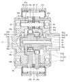
次に本発明の他の実施形態を説明する。図5は他の実施形態を示す縦断面図であり、インホイールモータ駆動装置の減速部を拡大して示す。他の実施形態につき、前述した実施形態と共通する構成については同一の符号を付して説明を省略し、異なる構成について以下に説明する。他の実施形態では減速部入力軸25を回転支持する転がり軸受38,39に高分子材料からなる緩衝部材63,65を設ける。   Next, another embodiment of the present invention will be described. FIG. 5 is a longitudinal sectional view showing another embodiment, and shows an enlarged view of a speed reduction portion of an in-wheel motor drive device. Regarding the other embodiments, the same reference numerals are given to the configurations common to the above-described embodiments, and the description thereof will be omitted, and different configurations will be described below. In another embodiment, buffer members 63 and 65 made of a polymer material are provided on the rolling bearings 38 and 39 that rotatably support the speed reduction unit input shaft 25.

減速部入力軸25からみてケーシング側部材になる減速部出力軸28および補強部材61は、転がり軸受38,39を介して減速部入力軸25を回転自在に支持する。軸受38は外輪38a、内輪38b、複数の転動体38c、および図示しない保持器を有する転がり軸受である。転がり軸受39も同様である。内輪38bと、内輪38bを貫通する減速部入力軸25との間には、高分子材料からなる緩衝部材63が介在する。緩衝部材63は環状の樹脂バンドであり、軸線O方向に間隔を空けて2箇所配置される。また内輪39bと、内輪39bを貫通する減速部入力軸25との間には、高分子材料からなる緩衝部材65が介在する。緩衝部材65は環状の樹脂バンドであり、軸線O方向に間隔を空けて2箇所配置される。図5に示す緩衝部材63,65の固定は、内輪38b,39bの内周面に環状溝を形成し、かかる環状溝に環状体の緩衝部材63,65を嵌合するとよい。緩衝部材63,65の材料、幅寸法および厚み寸法は、前述した実施形態の転がり軸受62、64の緩衝部材63、65と同じであり、また同様に転がり軸受38、39の内輪38b、39bと、これら内輪38b、39bが取り付けられる相手部材になる減速部入力軸25との嵌め合い状態および熱膨張差を考慮して決定される。   The speed reducer output shaft 28 and the reinforcing member 61 that are casing side members when viewed from the speed reducer input shaft 25 rotatably support the speed reducer input shaft 25 via rolling bearings 38 and 39. The bearing 38 is a rolling bearing having an outer ring 38a, an inner ring 38b, a plurality of rolling elements 38c, and a cage (not shown). The same applies to the rolling bearing 39. A buffer member 63 made of a polymer material is interposed between the inner ring 38b and the speed reducer input shaft 25 penetrating the inner ring 38b. The buffer member 63 is an annular resin band, and is arranged at two locations with a space in the direction of the axis O. Further, a buffer member 65 made of a polymer material is interposed between the inner ring 39b and the speed reducer input shaft 25 penetrating the inner ring 39b. The buffer member 65 is an annular resin band, and is arranged at two locations with a space in the direction of the axis O. The buffer members 63 and 65 shown in FIG. 5 may be fixed by forming annular grooves on the inner peripheral surfaces of the inner rings 38b and 39b and fitting the annular buffer members 63 and 65 into the annular grooves. The material, width dimension, and thickness dimension of the buffer members 63, 65 are the same as the buffer members 63, 65 of the rolling bearings 62, 64 of the above-described embodiment, and are similarly the inner rings 38b, 39b of the rolling bearings 38, 39. The inner ring 38b, 39b is determined in consideration of the fitting state with the speed reducer input shaft 25 to be a counterpart member to which the inner rings 38b, 39b are attached and the thermal expansion difference.

他の実施形態によれば図5に示すように、モータ側回転部材に含まれる減速部入力軸25をケーシング側部材に含まれる減速部出力軸28に回転自在に支持する転がり軸受39は、内輪39bおよび複数の転動体39cを含む転がり軸受である。また減速部入力軸25をケーシング側部材に含まれる補強部材61に回転自在に支持する転がり軸受38は、内輪38bおよび複数の転動体38cを含む転がり軸受である。そして内輪38bと、内輪38bを貫通する減速部入力軸25との間には、高分子材料からなる緩衝部材63が介在し、内輪39bと、内輪38bを貫通する減速部入力軸25との間には、高分子材料からなる緩衝部材65が介在する。これにより減速部入力軸25の振動が転がり軸受38,39に入力されても、この振動が減速部出力軸28および補強部材61に伝達することを抑制することができる。したがって減速部入力軸25よりもケーシング側になるケーシング22の振動を低減することができる。   According to another embodiment, as shown in FIG. 5, the rolling bearing 39 that rotatably supports the speed reduction unit input shaft 25 included in the motor side rotation member on the speed reduction unit output shaft 28 included in the casing side member includes an inner ring It is a rolling bearing including 39b and a plurality of rolling elements 39c. Further, the rolling bearing 38 that rotatably supports the speed reducing portion input shaft 25 on the reinforcing member 61 included in the casing side member is a rolling bearing including an inner ring 38b and a plurality of rolling elements 38c. A buffer member 63 made of a polymer material is interposed between the inner ring 38b and the speed reducer input shaft 25 penetrating the inner ring 38b, and between the inner ring 39b and the speed reducer input shaft 25 penetrating the inner ring 38b. There is a buffer member 65 made of a polymer material. Thereby, even if the vibration of the deceleration part input shaft 25 is input into the rolling bearings 38 and 39, it can suppress that this vibration is transmitted to the deceleration part output shaft 28 and the reinforcement member 61. Therefore, it is possible to reduce the vibration of the casing 22 that is closer to the casing than the speed reduction unit input shaft 25.

また他の実施形態によれば、図5に示すようにモータ側回転部材に含まれる減速部入力軸25が車輪側回転部材に含まれる減速部出力軸28に同軸配置され、減速部出力軸28の端部には減速部入力軸25の端部を受け入れる円形凹部34が形成される。減速部入力軸25をケーシング側部材に相当する減速部出力軸28に回転自在に支持する転がり軸受39は、円形凹部34の内周面と減速部入力軸25の外周面の間に画成される環状空間に設置され、緩衝部材65を伴う。これにより、ケーシング側部材が減速部出力軸28のように回転する部材であっても、減速部Bの内部からケーシング側部材へ振動が伝達することを抑制することができる。   According to another embodiment, as shown in FIG. 5, the speed reduction unit input shaft 25 included in the motor side rotation member is coaxially arranged with the speed reduction unit output shaft 28 included in the wheel side rotation member, and the speed reduction unit output shaft 28. A circular concave portion 34 that receives the end portion of the speed reduction portion input shaft 25 is formed at the end portion. A rolling bearing 39 that rotatably supports the speed reducer input shaft 25 on the speed reducer output shaft 28 corresponding to the casing side member is defined between the inner peripheral surface of the circular recess 34 and the outer peripheral surface of the speed reducer input shaft 25. And is provided with a buffer member 65. Thereby, even if a casing side member is a member rotating like the deceleration part output shaft 28, it can suppress that a vibration is transmitted from the inside of the deceleration part B to a casing side member.

なお図示はしなかったが、図5に示す実施形態の変形例として、内輪38b,39bの内周面に緩衝部材63,65を設けるのではなく、外輪38a,39aの外周面に緩衝部材63,65を設け、外輪38a,39aの外周面と車輪側回転部材の内周面との間に緩衝部材を介在させてもよい。あるいは外輪38a,39aの外周面と内輪38b,39bの内周面の双方に緩衝部材を設けてもよい。   Although not shown, as a modification of the embodiment shown in FIG. 5, the buffer members 63, 65 are not provided on the inner peripheral surfaces of the inner rings 38b, 39b, but the buffer members 63 are provided on the outer peripheral surfaces of the outer rings 38a, 39a. , 65 may be provided, and a buffer member may be interposed between the outer peripheral surface of the outer ring 38a, 39a and the inner peripheral surface of the wheel-side rotating member. Or you may provide a buffer member in both the outer peripheral surface of outer ring | wheel 38a, 39a and the inner peripheral surface of inner ring | wheel 38b, 39b.

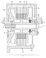
次に本発明のさらに他の実施形態を説明する。図6はさらに他の実施形態を示す縦断面図である。さらに他の実施形態につき、前述した実施形態と共通する構成については同一の符号を付して説明を省略し、異なる構成について以下に説明する。さらに他の実施形態ではモータ回転軸35を回転支持する転がり軸受36,37に高分子材料からなる緩衝部材63,65を設ける。   Next, still another embodiment of the present invention will be described. FIG. 6 is a longitudinal sectional view showing still another embodiment. Further, regarding the other embodiments, the same reference numerals are given to configurations common to the above-described embodiments, description thereof is omitted, and different configurations will be described below. In yet another embodiment, the rolling bearings 36 and 37 that rotatably support the motor rotating shaft 35 are provided with buffer members 63 and 65 made of a polymer material.

転がり軸受36は、外輪36a、内輪36b、複数の転動体36c、および図示しない保持器を有し、外輪36aの外周面がモータカバー22tの中心孔の内周面に取り付けられる。外輪36aとケーシング側部材に含まれるモータカバー22tとの間には、高分子材料からなる緩衝部材63が介在する。緩衝部材63は環状の樹脂バンドであり、軸線O方向に間隔を空けて2箇所配置される。   The rolling bearing 36 includes an outer ring 36a, an inner ring 36b, a plurality of rolling elements 36c, and a retainer (not shown), and the outer peripheral surface of the outer ring 36a is attached to the inner peripheral surface of the center hole of the motor cover 22t. A buffer member 63 made of a polymer material is interposed between the outer ring 36a and the motor cover 22t included in the casing side member. The buffer member 63 is an annular resin band, and is arranged at two locations with a space in the direction of the axis O.

転がり軸受37は、外輪37a、内輪37b、複数の転動体37c、および図示しない保持器を有し、外輪37aの外周面がポンプケーシング22pの中心孔の内周面に取り付けられる。外輪37aとケーシング側部材に含まれるポンプケーシング22pとの間には、高分子材料からなる緩衝部材65が介在する。緩衝部材65は環状の樹脂バンドであり、軸線O方向に間隔を空けて2箇所配置される。   The rolling bearing 37 includes an outer ring 37a, an inner ring 37b, a plurality of rolling elements 37c, and a retainer (not shown), and the outer peripheral surface of the outer ring 37a is attached to the inner peripheral surface of the center hole of the pump casing 22p. A buffer member 65 made of a polymer material is interposed between the outer ring 37a and the pump casing 22p included in the casing side member. The buffer member 65 is an annular resin band, and is arranged at two locations with a space in the direction of the axis O.

緩衝部材63,65の固定は、前述した図4に示すように、外輪36a,37aの外周面に環状溝を設けるとよい。緩衝部材63,65の幅寸法および厚み寸法は、前述したように転がり軸受36、37の外輪36a、37aと、これら外輪36a、37aの相手部材になるケーシング22との嵌め合い状態および熱膨張差を考慮して決定される。   As shown in FIG. 4 described above, the buffer members 63 and 65 may be fixed by providing annular grooves on the outer peripheral surfaces of the outer rings 36a and 37a. As described above, the width and thickness dimensions of the buffer members 63 and 65 are such that the outer rings 36a and 37a of the rolling bearings 36 and 37 and the casing 22 which is the counterpart member of the outer rings 36a and 37a are fitted and the thermal expansion difference. Is determined in consideration of

さらに他の実施形態によれば図6に示すように、モータ側回転部材に含まれるモータ回転軸35をケーシング22に回転自在に支持する転がり軸受36,37は、外輪36a,37aおよび複数の転動体36c,37cを含む転がり軸受であり、外輪36a,37aとケーシング22との間には、高分子材料からなる緩衝部材63,65が介在する。これによりモータ回転軸35の振動が転がり軸受36,37に入力されても、この振動がケーシング22に伝達することを抑制することができる。したがってケーシング22の振動を低減することができる。   According to still another embodiment, as shown in FIG. 6, the rolling bearings 36 and 37 that rotatably support the motor rotating shaft 35 included in the motor side rotating member on the casing 22 include outer rings 36a and 37a and a plurality of rolling bearings. It is a rolling bearing including moving bodies 36c, 37c, and buffer members 63, 65 made of a polymer material are interposed between the outer rings 36a, 37a and the casing 22. Thereby, even if the vibration of the motor rotating shaft 35 is input to the rolling bearings 36 and 37, the transmission of the vibration to the casing 22 can be suppressed. Therefore, the vibration of the casing 22 can be reduced.

またモータ側回転部材は、モータ部Aの一部でありモータ部Aから回転を出力するモータ回転軸35と、減速部Bの一部であり減速部Bに回転を入力する減速部入力軸25とを含み、ケーシング側部材はモータ部Aの一部であるポンプケーシング22pおよびモータカバー22tを含み、緩衝部材63,65は、モータ回転軸35をポンプケーシング22pおよびモータカバー22tに回転自在に支持する転がり軸受36,37に設けられる。
これにより、モータ回転軸35の振動が転がり軸受36,37に入力されても、この振動がモータカバー22tおよびポンプケーシング22pに伝達することを抑制することができる。
The motor-side rotating member is a part of the motor unit A and outputs a motor rotation shaft 35 that outputs rotation from the motor unit A, and a speed reduction unit input shaft 25 that is a part of the speed reduction unit B and inputs rotation to the speed reduction unit B. The casing side member includes a pump casing 22p and a motor cover 22t which are part of the motor part A, and the buffer members 63 and 65 rotatably support the motor rotating shaft 35 on the pump casing 22p and the motor cover 22t. The rolling bearings 36 and 37 are provided.
Thereby, even if the vibration of the motor rotating shaft 35 is input to the rolling bearings 36 and 37, this vibration can be prevented from being transmitted to the motor cover 22t and the pump casing 22p.

なお図示はしなかったが、図6に示す実施形態の変形例として、外輪36a,37aの外周面に緩衝部材63,65を設けるのではなく、内輪36b,37bの内周面に緩衝部材63,65を設け、内輪36b,37bの内周面とモータ回転軸35の外周面との間に緩衝部材を介在させてもよい。あるいは外輪36a,37aの外周面と内輪36b,37bの内周面の双方に緩衝部材を設けてもよい。   Although not shown, as a modification of the embodiment shown in FIG. 6, the buffer members 63 and 65 are not provided on the outer peripheral surfaces of the outer rings 36a and 37a, but the buffer members 63 are provided on the inner peripheral surfaces of the inner rings 36b and 37b. , 65 may be provided, and a buffer member may be interposed between the inner peripheral surface of the inner rings 36b, 37b and the outer peripheral surface of the motor rotating shaft 35. Or you may provide a buffer member in both the outer peripheral surface of the outer rings 36a and 37a, and the inner peripheral surface of the inner rings 36b and 37b.

以上、図面を参照してこの発明の実施の形態を説明したが、この発明は、図示した実施の形態のものに限定されない。図示した実施の形態に対して、この発明と同一の範囲内において、あるいは均等の範囲内において、種々の修正や変形を加えることが可能である。例えば上述した図3、図5、および図6の実施形態や、各実施形態の説明で附言した変形例の中から幾つかを選んで組み合わせてもよい。   Although the embodiments of the present invention have been described with reference to the drawings, the present invention is not limited to the illustrated embodiments. Various modifications and variations can be made to the illustrated embodiment within the same range or equivalent range as the present invention. For example, you may select and combine some from the embodiment of FIG.3, FIG.5 and FIG.6 mentioned above, and the modification added by description of each embodiment.

この発明になるインホイールモータ駆動装置は、電気自動車およびハイブリッド車両において有利に利用される。   The in-wheel motor drive device according to the present invention is advantageously used in electric vehicles and hybrid vehicles.

21 インホイールモータ駆動装置、 22 ケーシング、
22a モータケーシング、 22b 減速部ケーシング、
22p ポンプケーシング、 22t モータカバー、 23 ステータ、
24ロータ、 25 減速部入力軸、 25a,25b 偏心部、
26a,26b 曲線板、 27 外ピン、 28 減速部出力軸、
28b 大径フランジ部、 28c 小径フランジ部、 28d 軸部、 31 内ピン、 32 車輪ハブ、 33 車輪ハブ軸受、
34 円形凹部、 35 モータ回転軸、
36,37,38,39 転がり軸受、 36a,37a,38a,39a 外輪、
36b,37b,38b,39b 内輪、
36c,36c,37c,38c,39c 転動体、 45 外ピン保持部
61 補強部材、 61b 大径円板部、 61c 小径円板部、
61d 円筒部、 62,64 転がり軸受、 62b,64b 内輪
62a,64a 外輪 62c,64c 転動体 62d 環状溝、
63,65 緩衝部材、 A モータ部、 B 減速部、
C 車輪ハブ軸受部、 O 軸線、 X 自転軸心。
21 in-wheel motor drive device, 22 casing,
22a motor casing, 22b reduction gear casing,
22p pump casing, 22t motor cover, 23 stator,
24 rotor, 25 reduction part input shaft, 25a, 25b eccentric part,
26a, 26b Curved plate, 27 Outer pin, 28 Speed reducer output shaft,
28b Large diameter flange portion, 28c Small diameter flange portion, 28d Shaft portion, 31 Inner pin, 32 Wheel hub, 33 Wheel hub bearing,
34 circular recess, 35 motor rotating shaft,
36, 37, 38, 39 Rolling bearing, 36a, 37a, 38a, 39a Outer ring,
36b, 37b, 38b, 39b Inner ring,
36c, 36c, 37c, 38c, 39c rolling elements, 45 outer pin holding part
61 reinforcing member, 61b large-diameter disk part, 61c small-diameter disk part,
61d Cylindrical part, 62, 64 Rolling bearing, 62b, 64b Inner ring
62a, 64a outer ring 62c, 64c rolling element 62d annular groove,
63, 65 Buffer member, A motor part, B deceleration part,
C Wheel hub bearing, O axis, X Spindle shaft center.

Claims (7)

モータ側回転部材を駆動するモータ部と、前記モータ側回転部材の回転を減速して車輪側回転部材に出力する減速部とを備え、
前記モータ側回転部材をケーシング側部材に回転自在に支持する軸受、および/または前記車輪側回転部材をケーシング側部材に回転自在に支持する軸受は、外輪および複数の転動体を含む転がり軸受であり、
前記外輪と前記ケーシング側部材との間には、高分子材料からなる緩衝部材が介在することを特徴とする、インホイールモータ駆動装置。
A motor unit that drives the motor-side rotating member; and a speed-reducing unit that decelerates the rotation of the motor-side rotating member and outputs it to the wheel-side rotating member.
The bearing that rotatably supports the motor-side rotating member on the casing-side member and / or the bearing that rotatably supports the wheel-side rotating member on the casing-side member is a rolling bearing including an outer ring and a plurality of rolling elements. ,
An in-wheel motor drive device, wherein a buffer member made of a polymer material is interposed between the outer ring and the casing side member.
モータ側回転部材を駆動するモータ部と、前記モータ側回転部材の回転を減速して車輪側回転部材に出力する減速部とを備え、
前記モータ側回転部材をケーシング側部材に回転自在に支持する軸受、および/または前記車輪側回転部材をケーシング側部材に回転自在に支持する軸受は、内輪および複数の転動体を含む転がり軸受であり、
前記内輪と、該内輪を貫通する前記モータ側回転部材および/または前記車輪側回転部材との間には、高分子材料からなる緩衝部材が介在することを特徴とする、インホイールモータ駆動装置。
A motor unit that drives the motor-side rotating member; and a speed-reducing unit that decelerates the rotation of the motor-side rotating member and outputs it to the wheel-side rotating member.
The bearing that rotatably supports the motor side rotating member on the casing side member and / or the bearing that rotatably supports the wheel side rotating member on the casing side member is a rolling bearing including an inner ring and a plurality of rolling elements. ,
An in-wheel motor drive device characterized in that a buffer member made of a polymer material is interposed between the inner ring and the motor-side rotating member and / or the wheel-side rotating member penetrating the inner ring.
前記モータ側回転部材は、前記モータ部の一部であり該モータ部から回転を出力するモータ回転軸と、前記減速部の一部であり該減速部に回転を入力する減速部入力軸とを含み、
前記緩衝部材は、前記モータ回転軸を前記ケーシング側部材に回転自在に支持する軸受に設けられる、請求項1または2に記載のインホイールモータ駆動装置。
The motor-side rotating member includes a motor rotating shaft that is a part of the motor unit and outputs rotation from the motor unit, and a speed reducing unit input shaft that is a part of the speed reducing unit and inputs rotation to the speed reducing unit. Including
The in-wheel motor drive device according to claim 1, wherein the buffer member is provided in a bearing that rotatably supports the motor rotation shaft on the casing side member.
前記緩衝部材は、前記内輪の内周面、または前記外輪の外周面に沿って延びる環状体である、請求項1〜3のいずれかに記載のインホイールモータ駆動装置。   The in-wheel motor drive device according to any one of claims 1 to 3, wherein the buffer member is an annular body extending along an inner peripheral surface of the inner ring or an outer peripheral surface of the outer ring. 前記緩衝部材は、フッ素系高分子材料またはアクリル系高分子材料を主成分とする弾性体である、請求項1〜4のいずれかに記載のインホイールモータ駆動装置。   The in-wheel motor drive device according to any one of claims 1 to 4, wherein the buffer member is an elastic body mainly composed of a fluorine-based polymer material or an acrylic-based polymer material. 前記モータ側回転部材は前記車輪側回転部材に同軸配置され、
前記車輪側回転部材の端部には、前記モータ側回転部材の端部を受け入れる円形凹部が形成され、
前記モータ側回転部材を前記ケーシング側部材に回転自在に支持する軸受は、前記円形凹部の内周面と前記モータ側回転部材の外周面の間に画成される環状空間に設置され、前記緩衝部材を伴う、請求項1〜5のいずれかに記載のインホイールモータ駆動装置。
The motor side rotating member is coaxially arranged with the wheel side rotating member,
A circular recess that receives the end of the motor-side rotating member is formed at the end of the wheel-side rotating member,
A bearing that rotatably supports the motor-side rotating member on the casing-side member is installed in an annular space defined between an inner peripheral surface of the circular recess and an outer peripheral surface of the motor-side rotating member, and the buffer The in-wheel motor drive device in any one of Claims 1-5 with a member.
前記減速部は、前記モータ側回転部材に偏心して設けられた偏心部と、
前記偏心部に相対回転可能に保持され、前記モータ側回転部材の回転に伴って該モータ側回転部材の軸線を中心とする公転運動を行う公転部材と、
前記公転部材の外周に係合して前記公転部材の自転運動を生じさせる外周係合部材と、
前記公転部材の自転運動を前記モータ側回転部材の軸線を中心とする回転運動に変換して前記車輪側回転部材へ出力する運動変換機構とを有する、請求項6に記載のインホイールモータ駆動装置。
The speed reduction part is an eccentric part provided eccentric to the motor side rotation member;
A revolving member that is held in the eccentric part so as to be relatively rotatable, and performs a revolving motion around the axis of the motor side rotating member as the motor side rotating member rotates,
An outer periphery engaging member that engages with the outer periphery of the revolving member to cause the revolving motion of the revolving member;
The in-wheel motor drive device according to claim 6, further comprising: a motion conversion mechanism that converts the rotation motion of the revolution member into a rotation motion centering on an axis of the motor-side rotation member and outputs the rotation motion to the wheel-side rotation member. .
JP2014136463A 2014-07-02 2014-07-02 In-wheel motor drive device Pending JP2016014423A (en)

Priority Applications (1)

Application Number Priority Date Filing Date Title
JP2014136463A JP2016014423A (en) 2014-07-02 2014-07-02 In-wheel motor drive device

Applications Claiming Priority (1)

Application Number Priority Date Filing Date Title
JP2014136463A JP2016014423A (en) 2014-07-02 2014-07-02 In-wheel motor drive device

Publications (1)

Publication Number Publication Date
JP2016014423A true JP2016014423A (en) 2016-01-28

Family

ID=55230769

Family Applications (1)

Application Number Title Priority Date Filing Date
JP2014136463A Pending JP2016014423A (en) 2014-07-02 2014-07-02 In-wheel motor drive device

Country Status (1)

Country Link
JP (1) JP2016014423A (en)

Cited By (9)

* Cited by examiner, † Cited by third party
Publication number Priority date Publication date Assignee Title
CN109505925A (en) * 2017-09-13 2019-03-22 麦克赛尔控股株式会社 Speed reducer and the electrical equipment for having speed reducer
JP2019131009A (en) * 2018-01-30 2019-08-08 ミネベアミツミ株式会社 Wheel module and moving mechanism
JP2019131010A (en) * 2018-01-30 2019-08-08 ミネベアミツミ株式会社 Wheel module and moving mechanism
JP2019131008A (en) * 2018-01-30 2019-08-08 ミネベアミツミ株式会社 Wheel module and movement mechanism
CN110285198A (en) * 2019-07-23 2019-09-27 温州市日康烟具厂 A kind of cycloid reducer
JP2019183990A (en) * 2018-04-12 2019-10-24 住友重機械工業株式会社 Gear device
CN111503163A (en) * 2018-12-28 2020-08-07 株式会社荏原制作所 Bearing device and vacuum pump device
CN111684175A (en) * 2018-01-30 2020-09-18 美蓓亚三美株式会社 Wheel module and moving mechanism
JP2021108631A (en) * 2020-01-15 2021-08-02 株式会社シマノ Fishing reel

Cited By (13)

* Cited by examiner, † Cited by third party
Publication number Priority date Publication date Assignee Title
CN109505925A (en) * 2017-09-13 2019-03-22 麦克赛尔控股株式会社 Speed reducer and the electrical equipment for having speed reducer
CN111684175A (en) * 2018-01-30 2020-09-18 美蓓亚三美株式会社 Wheel module and moving mechanism
JP2019131009A (en) * 2018-01-30 2019-08-08 ミネベアミツミ株式会社 Wheel module and moving mechanism
JP2019131010A (en) * 2018-01-30 2019-08-08 ミネベアミツミ株式会社 Wheel module and moving mechanism
JP2019131008A (en) * 2018-01-30 2019-08-08 ミネベアミツミ株式会社 Wheel module and movement mechanism
CN111684175B (en) * 2018-01-30 2023-10-27 美蓓亚三美株式会社 Wheel module and moving mechanism
JP7084151B2 (en) 2018-01-30 2022-06-14 ミネベアミツミ株式会社 Wheel module and movement mechanism
JP7033995B2 (en) 2018-04-12 2022-03-11 住友重機械工業株式会社 Gear device
JP2019183990A (en) * 2018-04-12 2019-10-24 住友重機械工業株式会社 Gear device
CN111503163A (en) * 2018-12-28 2020-08-07 株式会社荏原制作所 Bearing device and vacuum pump device
CN110285198A (en) * 2019-07-23 2019-09-27 温州市日康烟具厂 A kind of cycloid reducer
JP2021108631A (en) * 2020-01-15 2021-08-02 株式会社シマノ Fishing reel
JP7281422B2 (en) 2020-01-15 2023-05-25 株式会社シマノ fishing reel

Similar Documents

Publication Publication Date Title
JP2016014423A (en) In-wheel motor drive device
JP5709373B2 (en) In-wheel motor drive device
WO2015104980A1 (en) In-wheel motor drive device
JP2009052630A (en) In-wheel motor drive unit
JP2015021570A (en) In-wheel motor driving device
JP2016161117A (en) Cycloid speed reducer and motor drive device with cycloid speed reducer
JP2017057901A (en) Motor drive unit for vehicle
JP2010255713A (en) In-wheel motor driving device
WO2016017351A1 (en) Cycloidal speed reducer and in-wheel motor drive device provided with same
JP6324761B2 (en) In-wheel motor drive device
JP6400297B2 (en) In-wheel motor drive device
JP2008184017A (en) In-wheel motor drive device
WO2015133278A1 (en) In-wheel motor drive device
WO2015046086A1 (en) In-wheel motor drive device
JP2008261445A (en) In-wheel motor drive device
WO2015137088A1 (en) In-wheel motor drive device
JP6328429B2 (en) In-wheel motor drive device
JP2016125628A (en) In-wheel motor driving device
JP2008168822A (en) In-wheel motor drive unit
JP2016023700A (en) Motor drive unit for vehicle
WO2016043011A1 (en) In-wheel motor drive device
WO2015137073A1 (en) In-wheel motor drive device
JP2012097903A (en) In-wheel motor driving device
WO2016043012A1 (en) In-wheel motor drive device
JP2009216104A (en) Railway vehicle drive unit