WO2015122289A1 - 情報処理装置および制御プログラム - Google Patents
情報処理装置および制御プログラム Download PDFInfo
- Publication number
- WO2015122289A1 WO2015122289A1 PCT/JP2015/052535 JP2015052535W WO2015122289A1 WO 2015122289 A1 WO2015122289 A1 WO 2015122289A1 JP 2015052535 W JP2015052535 W JP 2015052535W WO 2015122289 A1 WO2015122289 A1 WO 2015122289A1
- Authority
- WO
- WIPO (PCT)
- Prior art keywords
- client
- content
- server
- unit
- pairing
- Prior art date
- Legal status (The legal status is an assumption and is not a legal conclusion. Google has not performed a legal analysis and makes no representation as to the accuracy of the status listed.)
- Ceased
Links
Images













Classifications
-
- H—ELECTRICITY
- H04—ELECTRIC COMMUNICATION TECHNIQUE
- H04W—WIRELESS COMMUNICATION NETWORKS
- H04W60/00—Affiliation to network, e.g. registration; Terminating affiliation with the network, e.g. de-registration
- H04W60/06—De-registration or detaching
-
- H—ELECTRICITY
- H04—ELECTRIC COMMUNICATION TECHNIQUE
- H04L—TRANSMISSION OF DIGITAL INFORMATION, e.g. TELEGRAPHIC COMMUNICATION
- H04L67/00—Network arrangements or protocols for supporting network services or applications
- H04L67/14—Session management
- H04L67/143—Termination or inactivation of sessions, e.g. event-controlled end of session
-
- H—ELECTRICITY
- H04—ELECTRIC COMMUNICATION TECHNIQUE
- H04L—TRANSMISSION OF DIGITAL INFORMATION, e.g. TELEGRAPHIC COMMUNICATION
- H04L67/00—Network arrangements or protocols for supporting network services or applications
- H04L67/50—Network services
- H04L67/54—Presence management, e.g. monitoring or registration for receipt of user log-on information, or the connection status of the users
-
- H—ELECTRICITY
- H04—ELECTRIC COMMUNICATION TECHNIQUE
- H04L—TRANSMISSION OF DIGITAL INFORMATION, e.g. TELEGRAPHIC COMMUNICATION
- H04L67/00—Network arrangements or protocols for supporting network services or applications
- H04L67/50—Network services
- H04L67/60—Scheduling or organising the servicing of application requests, e.g. requests for application data transmissions using the analysis and optimisation of the required network resources
- H04L67/62—Establishing a time schedule for servicing the requests
-
- H—ELECTRICITY
- H04—ELECTRIC COMMUNICATION TECHNIQUE
- H04N—PICTORIAL COMMUNICATION, e.g. TELEVISION
- H04N21/00—Selective content distribution, e.g. interactive television or video on demand [VOD]
- H04N21/40—Client devices specifically adapted for the reception of or interaction with content, e.g. set-top-box [STB]; Operations thereof
- H04N21/43—Processing of content or additional data, e.g. demultiplexing additional data from a digital video stream; Elementary client operations, e.g. monitoring of home network or synchronising decoder's clock; Client middleware
- H04N21/436—Interfacing a local distribution network, e.g. communicating with another STB or one or more peripheral devices inside the home
- H04N21/43615—Interfacing a Home Network, e.g. for connecting the client to a plurality of peripherals
Definitions
- the present invention relates to an information processing apparatus that accepts a device registration request in a content transmission system that transmits content to a registered device registered in advance.
- Japanese Patent Publication “JP 2012-4916 A Japanese Patent Publication “Japanese Patent Laid-Open No. 2006-31097 (published on February 2, 2006)” Japanese Patent Publication “JP 2001-326720 A” (published on November 22, 2001) Japanese Patent Publication “Japanese Patent Laid-Open No. 2012-199753” (published on October 18, 2012) Japanese Patent Publication “JP 2011-278244 A” (published on December 20, 2011)
- the present invention has been made in view of the above-described problems, and an object thereof is to provide an information processing apparatus and the like that can easily select an appropriate device as a registration cancellation target.
- an information processing apparatus provides a device registration in a content transmission system that transmits content to a registered device in response to a request from a registered device registered in advance.
- An information processing apparatus that accepts a request, and when a registration request is received in a state where the number of registered devices has reached the upper limit, a cancellation candidate selection that selects a cancellation candidate that is a candidate for canceling registration from the registered devices And a candidate presentation unit that presents the release candidate to the user and selects whether or not the release candidate can be deregistered.
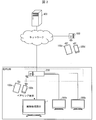
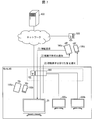
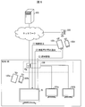
- FIG. 2 is a diagram showing an outline of the content transmission system.
- broadcast content received in real time by a server at home is transmitted to client devices outside the home in real time.
- content transmission can be performed by using DTCP +.
- the user can view the broadcast content outside the home in substantially real time.
- the transmission timing does not have to be substantially real time, and the content to be transmitted is not limited to the broadcast content.
- the content transmission system includes a server (information processing device, content transmission device) 1, portable client devices (devices, registered devices, release candidates) 100a to 100d, and stationary client devices 300a and 300b.
- portable client devices 100a to 100d may be abbreviated as client devices 100a to 100d or client devices.
- the content transmission system includes a router 200 that connects a home LAN (local area network) and a communication network (such as the Internet) outside the home, an access management server 400 for accessing the server 1 from outside the home, and from outside the home.
- An access point 500 for connecting to a network is included.
- the client devices 100 c and 100 d outside the home communicate with the server 1 by connecting to the access management server 400 via the access point 500 and acquiring the communication address of the server 1 registered in advance in the access management server 400. It becomes possible.
- the server 1 is a server that transmits contents to client devices inside or outside the house.
- the server 1 transmits the content to the requesting client device via the home LAN. Further, when the content is requested from the client device 100c or 100d outside the home, the server 1 transmits the content to the requesting client device via the communication network outside the home.
- the server 1 when the server 1 receives a content request from outside the home, the server 1 transmits the content only when the request source is a previously paired client device. That is, the above pairing means registering a client device that can receive content from the server 1 via a communication network outside the home (outside the LAN).
- the client devices 100a to 100d need to request pairing from the server in advance and have the server 1 register them as devices that can receive the content from outside the home.
- a pairing request registration request
- a configuration that allows pairing from outside the house may be used.
- the server 1 places a limit on the number of client devices that can be paired. For this reason, when the number of paired client devices has reached the upper limit, if a pairing request is further received, pairing will be performed according to the pairing request unless the pairing of any client device is released. Can't do it.
- the server 1 automatically selects a client device candidate (hereinafter referred to as a cancellation candidate) that seems to have no problem even if the pairing is canceled, and presents it to the user.
- a client device candidate hereinafter referred to as a cancellation candidate
- the user can easily select a client device that is appropriate for canceling the pairing (which is expected to be unlikely to cause trouble), and can pair a new client device with the server 1. become.
- FIG. 1 is a block diagram showing a main configuration of the server 1.
- the server 1 includes a control unit 2, a storage unit 3, a communication unit 4, a display unit 5, an input unit 6, and a content memory 7.
- the control unit 2 controls and controls each unit of the server 1, and includes a content transmission unit 10, a pairing management unit (cancellation candidate selection unit, candidate presentation unit) 11, a pairing unit 12, a position determination unit (device) A detection unit) 13, a residence time specifying unit (residence time specifying unit) 14, and a frequency specifying unit (frequency specifying unit) 15.
- the storage unit 3 stores various data used by the server 1.
- the illustrated storage unit 3 includes a paired device management information storage unit 3a.
- the communication unit 4 is for the server 1 to communicate with other devices, and the server 1 communicates with the client devices 100a to 100d through the communication unit 4.
- the input unit 6 inputs content acquired from the outside to the content memory 7.
- the input unit 6 is a tuner that acquires content from broadcast waves received by the server 1 and inputs the content to the content memory 7.
- the input unit 6 is not particularly limited as long as content can be input to the content memory 7.
- the input unit 6 may acquire content from a recording device such as a hard disk or a recording medium such as a BD disk and input the content to the content memory 7.
- the content memory 7 is a memory that stores the content output from the input unit 6.
- the display unit 5 is a display device that displays an image according to the control of the control unit 2. That is, the server 1 has a function as a television receiver that receives and displays broadcast content.
- the display unit 5 and the input unit 6 may be external devices externally connected to the server 1.
- the pair device management information storage unit 3a stores pair device management information for managing paired client devices. Details of the pair device management information will be described later.
- the content transmission unit 10 transmits content in response to a request from the client device. However, when a content transmission request is received from outside the house, the content transmission unit 10 checks whether the transmission source device of the request is registered in the paired device management information, and only when the content transmission request is registered Send.
- the pairing management unit 11 performs processing related to pairing between the server 1 and the client device. Specifically, when the pairing management unit 11 receives a pairing request in a state where the number of paired devices has not reached the upper limit, the pairing management unit 11 instructs the pairing unit 12 to pair with the device. Run the ring. On the other hand, when a pairing request is received in a state where the number of paired devices has reached the upper limit, the pairing management unit 11 cancels pairing cancellation from the registered client devices. Select a candidate. Then, the pairing management unit 11 presents the selected cancellation candidate to the user, and selects whether or not the cancellation candidate pairing cancellation (registration cancellation) is possible. Note that selection and presentation of cancellation candidates may be executed in different processing blocks.
- the pairing unit 12 performs pairing with the client device in accordance with instructions from the pairing management unit 11. Specifically, the pairing unit 12 performs pairing with the client device by registering the device ID and communication address of the client device instructed from the pairing management unit 11 in the paired device management information.
- the position determination unit 13 determines, for each paired client device, whether the client device exists in the home. Specifically, the position determination unit 13 transmits a response request to each device in the home LAN, and determines that a device that has returned a response to the response request exists in the home. That is, the position determination unit 13 detects a paired client device that is connected to the home LAN. Note that the method for determining whether or not the device is in the house is not limited to this. For example, when the client device includes a GPS (Global Positioning System) receiver, the client device transmits the position information of the device, If the position indicated by the position information is within a predetermined range from the position of the server 1, it may be determined that it exists in the house.
- GPS Global Positioning System
- the residence time specifying unit 14 for each paired client device specifies the accumulated time that the client device exists in the home, and records the identified accumulated time as the residence time of the client device.
- the accumulated time connected to the home LAN is the accumulated time existing in the home, but for example, the location information can be connected to the home LAN by using the location information described above.
- the accumulated time may be specified and used as the residence time in the house.
- the frequency identification unit 15 identifies and records the content acquisition frequency from outside the home of the client device for each paired client device.
- information indicating the frequency an example in which the number of times a content transmission request is received from outside the house during a predetermined period (for example, one day) will be described as information indicating the frequency.
- the information to be recorded is content from outside the house. Anything that indicates the acquisition frequency may be used, and the present invention is not limited to this example.
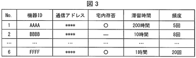
- FIG. 3 is a diagram illustrating an example of pair device management information.
- the paired device management information shown in the figure is a table format in which a device ID, a communication address, information indicating whether or not the device is present, information indicating the staying time in the home, and information indicating the frequency of content acquisition from outside the home are associated with each other. Information.
- the device ID is identification information for identifying the client device.
- the device ID may be any information that can uniquely identify each paired client device.
- the device ID may be a device name preset by the user, a user name of the device, a device model name, or the like.
- the communication address is a communication address for communicating with the client device. By using this communication address, content can be transmitted to a client device outside the home. Such information is recorded at the time of pairing, for example.
- the information indicating whether or not the home exists is information indicating whether or not the client device exists in the home. As described above, the position determination unit 13 determines whether the client device exists in the home. Then, the position determination unit 13 records the determination result in the pair device management information as information indicating whether the client device exists in the house. The information indicating whether the client device is in the house may be recorded as data different from the pair device management information.
- the information indicating the residence time in the home is information indicating the accumulated time that the client device has been in the home.
- the residence time specifying unit 14 specifies the accumulated time that the client device has been in the house. Then, the residence time specifying unit 14 records this identification result in the pair device management information as information indicating the residence time of the client device.
- the information indicating the residence time in the house may be recorded as data different from the paired device management information.
- the information indicating the content acquisition frequency from outside the home is information indicating the frequency at which the client device has acquired the content from the server 1 outside the home.
- the frequency acquisition unit 15 specifies the frequency of content acquisition from outside the house.
- the frequency identification unit 15 records the identification result in the pair device management information as information indicating the frequency of content acquisition from outside the home of the client device.
- Information indicating the frequency of content acquisition from outside the house may be recorded as data different from the paired device management information.
- FIG. 6 is a flowchart illustrating an example of the pairing process. Note that the processing in the figure is started when a pairing request is received from the client device. Further, it is assumed that the server 1 receives the device ID of the client device together with the pairing request.
- the pairing management unit 22 acquires pair device management information from the pair device management information storage unit 3a (S1), and determines whether the client device that is the pairing request source is unregistered in the pair device management information (S2). ). If it is determined that registration has been completed (NO in S2), the pairing management unit 22 ends the pairing process without performing pairing. On the other hand, when it is determined that it is not registered (YES in S2), the pairing management unit 22 determines whether the number of registered devices has reached the upper limit (S3).
- the pairing management unit 22 instructs the pairing unit 23 to execute pairing with the client device (S14).
- the management information is updated (S15), and the pairing process is terminated.
- the pairing management unit 22 instructs the position determination unit 24 to check whether each registered device exists in the home. Let it be judged. Then, according to the determination result, the pairing management unit 22 generates a home device list that is a list of registered devices existing in the home and a non-home device list that is a list of other registered devices ( S4).
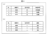
- FIG. 4 is a diagram illustrating an example of a home device list and a non-home device list.
- a record of “ ⁇ ” in the home presence / absence from the pair device management information in FIG. 3, that is, a record related to the client device detected to be connected to the home LAN is extracted.
- cancellation candidates are determined from the home device list based on the residence time in the home, so information indicating the residence time is also extracted from the pair device management information.
- 3B is a record of “ ⁇ ” in the home presence / absence from the pair device management information in FIG. 3, that is, a client device that is not detected to be connected to the home LAN.
- the cancellation candidate is determined from the non-home device list based on the content acquisition frequency from outside the home, information indicating the frequency is also extracted from the pair device management information.
- the pairing management unit 22 determines whether a device is included in the generated home device list (S5).
- the pairing management unit 22 determines a pairing cancellation candidate from the home device list based on the information indicating the stay time in the home (S6). .
- the pairing management unit 22 sorts the home device list in descending order using the home residence time as a key, and determines the first device, that is, the device with the longest home residence time, as a pairing release candidate. Then, the pairing management unit 22 presents the determined pairing cancellation candidates to the user, for example, by displaying them on the display unit 5 (S7).
- the pairing management unit 22 selects the cancellation candidate from the non-home device list based on the information indicating the content acquisition frequency from outside the home. (S8). Specifically, the pairing management unit 22 selects the first device that sorts the non-home device list in ascending order using the frequency as a key, that is, the device with the lowest frequency.
- the pairing management unit 22 determines whether content is being viewed on the selected device (S9). Specifically, when the device that is transmitting the content matches the device selected in S8, the distribution unit 21 determines that the device is currently viewing the content.
- the process proceeds to S7, and the cancellation candidate selected in S8 is presented to the user.
- the pairing management unit 22 determines the next candidate as a cancellation candidate (S10), proceeds to the processing of S7, and presents the cancellation candidate to the user.
- next candidate is a device having the second lowest frequency among the devices included in the non-home device list.
- the number of devices that can receive content distribution from the server 1 from outside the home is limited to one, even in the device with the second lowest frequency, The content distributed from the server 1 cannot be viewed.
- the determination in S9 may be performed until devices with no content viewing are found in order for devices with the second and subsequent frequencies.
- the pairing management unit 22 determines whether the user has agreed to cancel the pairing of the cancellation candidate (S11). For example, an option for whether or not to cancel can be displayed on the display unit 5 and the above determination can be made according to the content selected by the user.
- the pairing management unit 22 performs an exception process (S12) and ends the pairing process.
- the next cancellation candidate for example, the device with the longest residence time next to the cancellation candidate for which consent has not been obtained, or the frequency of content acquisition from outside the house next to the cancellation candidate for which consent has not been obtained is low.
- the process of presenting the device to the user may be repeated until the user's consent is obtained.
- the registered devices are displayed in a list (FIG. 5A) together with information for each device such as presence / absence in the home, residence time, frequency, etc., and the user is allowed to select a device to be paired. The user may be prompted to select a device to cancel pairing, or the pairing may not be canceled and the requested pairing may not be performed.
- the pairing management unit 22 deletes the cancellation candidate device from the paired device management information, and Pairing is canceled (S13). Then, the pairing management unit 22 instructs the pairing unit 23 to execute pairing with the client device (S14), updates the pair device management information (S15), and ends the pairing process.
- FIG. 5 is a diagram illustrating an example of an image presented to the user.
- the number of devices that can be paired has already reached the upper limit, and it is necessary to select a device to cancel pairing for a new pairing.
- a message indicating is included.
- the device ID of the device that has made the pairing request is included.
- the client device information is not deleted from the paired device management information, but information indicating that pairing is cancelled is added and left in the paired device management information.
- the residence time and the like can be presented as in the illustrated example. Of course, presentation of information such as residence time is not essential.
- the image of (a) in the figure includes an option for selecting whether or not pairing can be executed and a list of paired devices.
- cancellation candidates determined by the server 1 are focused (highlighted), and a cursor (arrow) for the user to select a device to be canceled is placed on the cancellation candidates.
- the user can easily select an appropriate release candidate. You can choose. Although only the cancellation candidates determined by the server 1 may be presented to the user, it is preferable to display other devices in a selectable manner because the range of selection by the user is widened. In the illustrated example, one cancellation candidate determined by the server 1 is highlighted. However, a plurality of cancellation candidates may be highlighted and presented in a similar manner, and it is considered more appropriate as a cancellation candidate. A plurality of release candidates may be presented in order.
- an image as shown in (b) of the figure is displayed, and the user can confirm whether or not pairing with the selected device can be canceled.
- the image of (b) in the figure shows the ID of the device selected by the user, information indicating that the device is a pairing cancellation candidate, and the judgment criteria for selecting the device as a cancellation candidate.
- the residence time of the device is shown.
- the image includes a message inquiring whether or not pairing of the device can be canceled and an option for selecting whether or not the device can be paired.
- the user By displaying such an image, the user has a long residence time at home, and is unlikely to be used for viewing content outside the home, or even when pairing is canceled, It is possible to recognize that a device that is easily paired again is a release candidate. Based on such recognition, it is possible to make a final determination as to whether or not to cancel pairing with the device.
- FIGS. 5A and 5B may be displayed on the client device, and the server 1 uses the input content of the user input to the client device based on this image as the client device. May be received and the determination of S11 may be made.
- registered client devices existing in the home are set as release candidates in preference to client devices that have not been confirmed to exist in the home. This is because a client device connected to the home LAN can receive desired content from the server 1 even if the pairing is canceled. Further, as described above, it is assumed here that pairing is possible only when connected to the home LAN. For this reason, even if it is a case where the pairing of the client apparatus contrary to a user's will is cancelled
- all the client devices determined to be present in the home in (1) may be set as cancellation candidates.
- the cancellation candidate may be determined by using only the criterion (2) or (3) or a combination of these criteria without using the criterion (1).
- cancellation candidates may be determined by combinations of all the criteria (1) to (3).
- the selection criteria for cancellation candidates are not limited to the above examples (1) to (3).
- a client device having a long period of time during which no viewing (reception of content from the server 1) has been performed may be given priority as a cancellation candidate. This is because client devices that have not been used for viewing outside the home for a long period of time are often less affected even when pairing is canceled.
- the server 1 may be provided with a non-reception period specifying unit (non-reception period specifying unit) that acquires non-reception period information indicating a period during which the client device does not receive content from the server 1 outside the home LAN. . Then, based on the non-reception period information, the pairing management unit 11 may preferentially select a client device having a longer period of not receiving content as a cancellation candidate.
- the timing at which the content is last received may be the timing at which the content transmission request is received, the timing at which the content transmission is started, or the timing at which the content transmission is terminated. Also good. Further, this timing may be indicated by a date and time, or may be indicated by a date. Furthermore, instead of such a recent non-reception period, a cumulative non-reception period may be used.
- the priority of pairing may be set for the client device, and the client device with a lower priority may be given priority as a release candidate.
- the priority may be set based on this information by registering information about the paired client device at the time of the first pairing, for example. Specifically, for example, a parent-child relationship, age, and the like may be registered for a user of a client device, and it may be determined that a parent has a higher priority than a child and an older person has a higher priority than a younger person.
- the priority may be set by the user, and a client device with a low priority may be given priority as a cancellation candidate.
- the server 1 may be provided with a priority determination unit (priority determination unit) that determines the priority of the client device based on information about the client device registered in advance. And the pairing management part 11 should just select a cancellation
- a priority determination unit priority determination unit
- a client device with a shorter usage time or a lower usage frequency may be given priority as a cancellation candidate. This is because a client device having a high usage frequency is considered to have a larger influence when pairing is canceled than a client device having a low usage frequency.
- the server 1 may be provided with a usage status specifying unit (usage status specifying unit) that specifies the accumulated usage time or usage frequency of the client device. Then, the pairing management unit 11 may prioritize the client device with the shorter cumulative usage time specified by the usage status specifying unit or the client device with a lower usage frequency as a cancellation candidate.
- the accumulated usage time may be obtained by measuring the time that the device is used (for example, the time when the power is on and not in the sleep state) in the client device, and acquiring the measured time from the device. Good.
- the frequency of use for example, in a client device, counts the number of times that the device has been used (number of times of use) (for example, the number of times the power is turned on or the sleep state is canceled). You may acquire from this apparatus. And it is good also considering the frequency
- the number and frequency of use in a predetermined manner for example, usage for viewing content, use of a specific application, etc. are not limited to the number and frequency acquired from the server 1) may be used. .
- Appropriate cancellation candidates can be selected by combining various criteria as described above alone or appropriately.
- the pairing requesting device has a lower priority for pairing, and it is determined that the pairing is canceled rather than the pairing cancellation based on the above criteria. It may be more appropriate to cancel a ring request. In such a case, a message to that effect may be presented to the user to select whether to cancel the pairing request. Thereby, in order to pair with a low priority apparatus, it can prevent releasing a pairing of a high priority apparatus.
- the priority determination unit (priority determination unit) that determines whether the server 1 has a lower registration priority than the paired client device according to a predetermined criterion. May be provided. Then, when the priority determination unit determines that the device that is the source of the pairing request has a lower registration priority than the paired client device, the pairing management unit 11 displays the determination result. Notify the user and select whether or not to accept a pairing request.
- the above criterion may be the same as the criterion for selecting a cancellation candidate.
- the cancellation candidate may be selected from all paired client devices and devices that have requested pairing.
- the priority level may be determined between the cancellation candidate and a device requesting pairing. In any of these configurations, it is possible to prevent pairing of a client device having a high priority from being canceled.
- the pairing management unit 11 selects one cancellation candidate according to the above criteria, cancels the pairing of the selected cancellation candidate, and instead performs pairing with the transmission source device of the pairing request. .
- pairing cancellation may be automatically performed when a client device that is a cancellation candidate satisfies requirements such as not acquiring content from outside the home for a predetermined period (for example, one year). .
- the control block (especially the control unit 2) of the server 1 may be realized by a logic circuit (hardware) formed in an integrated circuit (IC chip) or the like, or realized by software using a CPU (Central Processing Unit). May be.
- a logic circuit hardware
- IC chip integrated circuit
- CPU Central Processing Unit
- the server 1 includes a CPU that executes instructions of a program that is software that implements each function, a ROM (Read Only Memory) or storage in which the above-described program and various data are recorded so as to be readable by a computer (or CPU).
- a device (these are referred to as “recording media”), a RAM (Random Access Memory) for expanding the program, and the like are provided.
- the objective of this invention is achieved when a computer (or CPU) reads the said program from the said recording medium and runs it.
- a “non-temporary tangible medium” such as a tape, a disk, a card, a semiconductor memory, a programmable logic circuit, or the like can be used.
- the program may be supplied to the computer via an arbitrary transmission medium (such as a communication network or a broadcast wave) that can transmit the program.
- a transmission medium such as a communication network or a broadcast wave
- the present invention can also be realized in the form of a data signal embedded in a carrier wave in which the program is embodied by electronic transmission.
- Reference Example 1-1 A reference example of the present invention will be described with reference to FIGS. In this reference example, a configuration will be described in which a user of a certain client device can easily recognize that there is a viewing request (content transmission request) from another client device.
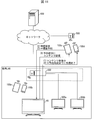
- Figure 7 shows an overview of the content transmission system according to this reference example. 7 shows four client devices 100a to 100d, it is assumed that the server 20 is paired with six client devices including the four client devices.
- the client device may be a device dedicated to the server 20 (slave device) or a general-purpose device such as a mobile phone or a smartphone.
- the server 20 according to the reference example 1-1 has the same configuration as the server 1 described in the first and second embodiments. That is, the server 20 includes a control unit 2, a storage unit 3, a communication unit 4, a display unit 5, an input unit 6, and a content memory 7 (see FIG. 1). However, as described below, the function of the control unit 2 is different from that of the above embodiment.
- the information processing apparatus (server 20) according to Reference Example 1-1 is a content transmission system that transmits content to a registered device in response to a viewing request from a registered device (client devices 100a to 100d) registered in advance.
- An information processing apparatus that limits the number of registered devices that simultaneously receive content, and when content viewing requests are received when the number of registered devices that simultaneously receive content has reached the upper limit,
- the control unit (2) includes a notification unit that notifies the registered device that has received the notification that the content viewing request has been received from another registered device.
- a certain client device is receiving content from the server 20 (that is, a user of the client device is viewing the content, and a user of another client device cannot view the content).
- the client device is expressed as “viewing right”.
- the user of the second client device wants to view the content immediately, it is necessary to search for the user of the first client device having the viewing right and request to stop viewing the content. Also, the user of the first client device cannot recognize that there is a viewing request from the second client device even if he / she thinks that viewing of the content may be stopped if there is a viewing request of another user. Therefore, I could not take any concrete action.
- the user of the first client device can easily recognize that there is a viewing request from the second client device. That is, as illustrated in FIG. 7, when the server 20 receives a viewing request from the client device 100c while transmitting content to the client device 100d (1), the notification unit displays the client device 100c. (2) and the client device 100d is notified that a viewing request has been received (3). Thereby, the user of the client device 100d receiving the content from the server 20 can easily recognize that there is a viewing request from another user.
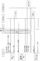
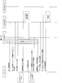
- FIG. 8 is a diagram showing a sequence of operations of the server 20 and six client devices (including client devices 100a to 100d) in the content transmission system shown in FIG.
- client No. 1 when one client device 100d (hereinafter referred to as client No. 1) of the six client devices paired with the server 20 has the viewing right, another one client device An example in which a viewing request is transmitted from the device 100c (hereinafter referred to as client No. 2) to the server 20 will be described. The remaining four client devices are assigned client numbers. Called 3-6.
- Client No. The control unit 2 of the server 20 that receives the viewing request from the client 2 receives the client number. 2 is notified that content viewing is not permitted (since client No. 1 is currently viewing the content and No. 2 has no viewing right).
- the notification unit displays the client number that has the viewing right. 1 to client No. 2 that the request for viewing has been received. At this time, the notification unit selects the client number from the six paired clients. 2 (client information) for specifying the client No. 2 3 is notified.
- the client information may be information that can uniquely identify the client device.
- the model number of 2 may be sufficient.
- the client No. registered in the server 20 is also displayed. 2 incidental information, for example, client No. 2 user name, age, and gender. 2 model names may be included.
- the client information is the client number. 2 requested content identification information (name, title, program code, etc.) or client number. Information on the state of 2 (position, whether or not moving, remaining battery capacity) may be included. Further, client No. If the 2 is a 3G mobile phone or the like having a function of notifying information indicating the radio wave state, the client No. Information indicating two radio wave conditions may be included.
- Client No. 1 is a client number. 2, a message explaining that the server 20 has received a content viewing request from the client 2, and a client number. 2 client information, the client number. 1 is displayed on the screen. This message and client information may be displayed overlapping (overlapping) with the content, or displayed in a screen area different from the screen area where the content is displayed, that is, without being superimposed on the same screen. May be.
- Client No. that confirmed the message One user can easily recognize that there is a content viewing request. Further, client No. Whether or not to stop viewing the content can be determined based on the client information 2.
- the notification part of the server 20 is the client number. 3 to 6 also have client No. 2 may be notified that a viewing request has been received. In this configuration, the client No. It can be expected that the users 3 to 6 recognize that the viewing request has already been transmitted (the viewing request is crowded) and do not transmit the viewing request unnecessarily.
- the server 20 has the client No. Support can be provided so that 1 to 6 users can view content smoothly.
- FIG. 9 is a diagram showing an outline of a content transmission system according to this reference example.
- the content transmission system shown in FIG. 9 is different from the content transmission system shown in FIG. 7 in that a server 30 is provided instead of the server 20.
- the server 30 has the same configuration as that of the server 20, but as described below, is different from the server 20 in that the function of the control unit 2 is further added.
- control unit (2) includes a registered device (source of a content viewing request) ( The information processing apparatus further includes an information transmitting unit that transmits information (viewing information) related to the registered device receiving the content to the client devices 100a to 100d).
- client No. 1 has the right to view the content, 2 does not allow the server 20 to view the content. The second user cannot view the content.
- Client No. The user No. 2 cannot view the content because the client No. It is not known whether it is due to the second problem, a communication problem, or another user is viewing the content.
- client No. 2 the server 30 (the information transmission unit of the control unit 2) receives the client number. 1 indicates that the content is being viewed. 2 is notified. That is, as shown in FIG. 9, when the server 30 is transmitting content to the client device 100d and receives a viewing request from the client device 100c (1), the notification unit sends the request to the client device 100c. On the other hand, notifying viewing is not permitted (2), and the information transmitting unit notifies viewing information (3).
- the viewing information is information regarding the content being viewed on the client device 100d itself, the user of the client device 100d, or the client device 100d. Therefore, the user of the client device 100c can easily recognize the situation where viewing is not possible.
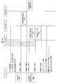
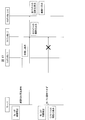
- FIG. 10 is a diagram showing a sequence of operations of the server 30 and six client devices (including client devices 100a to 100d) in the content transmission system shown in FIG.
- the client number 1 has the right to view the content.
- the client No. 2 transmits a content viewing request to the server 30.
- the notification unit of the server 30 that has received the viewing request from the client 2 receives the client number. 2 is notified that content viewing is not permitted (since client No. 1 is currently viewing the content and No. 2 has no viewing right).
- the information transmission unit of the server 30 is a client No. having viewing rights. 1 to client No. 2 that the request for viewing has been received. At this time, the information transmission unit of the server 30 receives the client number. 1 to client No. Requests to transmit viewing information indicating the viewing state of 1. Client No. 1 receives the request and transmits viewing information to the server 30.
- the viewing information is the client number. It may be information indicating the position of 1, whether or not it is moving, the orientation of the screen (portrait or landscape), the remaining battery level, the radio wave condition, and the like. Alternatively, the content (title, live or recording, remaining time) of the content being viewed, or the client No. One user name may be used.
- the information transmission unit of the server 30 is a client No. 2 for client no. 1 viewing information is transmitted. Further, the information transmission unit of the server 30 is a client No. 1 in addition to the viewing information of the client No. 1
- the incidental information of No. 1 is also client No. 2 to send.
- the incidental information is the client number. 1 user name, age, gender, or client No. 1 model name may be used.
- the information transmission unit of the server 30 is a client No. 1 shows the viewing time or cumulative viewing time of the content in client No. 2 may be transmitted.
- Client No. 2 displays the received viewing information and incidental information.
- the information transmission unit of the server 30 is a client No. 2 as well as client no. 3-6 are also notified of viewing information and incidental information.
- the client No. The users 3 to 6 also have client nos. 1 can know the viewing state of the content.
- client No. 2 has a client No.
- a comment for one user may be transmitted to the server 30.
- the information transmission part of the server 30 is client no.
- the comment received from the client No. 2 1 may be transmitted.
- client No. 2 the client No. 2 received from the server 30. 1, based on the viewing information and incidental information of client 1. It is possible to determine whether or not one user is to stop viewing the content. In addition, client No. It is also possible to send a comment to one user and prompt the user to stop viewing.
- FIG. 11 is a diagram showing an outline of a content transmission system according to this reference example.
- the content transmission system shown in FIG. 11 is different from the content transmission system shown in FIG. 7 in that a server 40 is provided instead of the server 20.
- the server 40 has the same configuration as that of the server 20, but is different from the server 20 in that the function of the control unit 2 is further added as described below.
- the control unit (2) determines that the number of registered devices that simultaneously receive content is the same.
- a reservation is made so that the registered device that has sent the viewing request receives the content after the time when the content reception ends at the registered device that is receiving the content. It is characterized by including a part.
- the client No. 2 is a client number.
- the right to view the content cannot be obtained until the viewing of the content at 1 is completed.
- client No. 1 is finished, another client no.
- the client No. 2 users have different client numbers. It is necessary to wait further until the viewing at 3-6 ends. Therefore, client no. There is a possibility that the second user may not know when the content can be viewed.
- the reservation part of the server 40 is the client No. 2, an example of accepting a reservation for viewing content will be described. That is, as shown in FIG. 11, when the server 40 is transmitting content to the client device 100d (1), when a viewing request is received from the client device 100c (2), viewing permission cannot be obtained.
- the client device 100c makes a viewing reservation with the server 40 (3).
- the reservation unit of the server 40 accepts this viewing reservation.
- the client device 100d finishes receiving the content by the reservation time (4), and transmits the content reserved to the client device 100c from the reservation unit of the server 40 at the reservation time. Therefore, the user of the client device 100c can start viewing desired content immediately after the viewing on the client device 100d is completed.
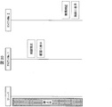
- FIG. 12 is a diagram showing a sequence of operations of the server 40 and six client devices (including client devices 100a to 100d) in the content transmission system shown in FIG.
- client No. 1 when one client device 100d (hereinafter referred to as client No. 1) of the six client devices paired with the server 40 has the viewing right, the other one client An example in which a viewing request is transmitted from the device 100c (hereinafter referred to as client No. 2) to the server 40 will be described.
- the remaining four client devices are assigned client numbers. Called 3-6.
- the reservation unit of the server 40 that has received the viewing request from the client 2 receives the client number. 2 is inquired whether the content to be viewed is live content (a television program being broadcast) or recorded content (content stored in a recorder or the like).
- Client No. 2 receives an inquiry from the server 40 and notifies the server 40 whether to specify recorded content or live content.
- the server 40 is notified that the recorded content is designated. Since live content cannot be viewed after the end of broadcasting, it is not subject to reservation.
- the reservation part of the server 40 is the client No. 2 receives a notification that the recorded content is to be specified, generates a list of recorded content, and displays the generated recorded content list as a client number. 2 to send.
- Client No. 2 displays a list of recorded contents received from the server 40.
- Client No. The second user designates the content to be viewed from the displayed list of recorded content.
- the client 2 notifies the server 40 of the content specified by the user.
- the reservation part of the server 40 is the client No. 1 after the content viewing time (time after the viewing end time). 2 indicates the time zone corresponding to the length of the content specified by the client No. 2 is secured as a time (reservation time) for permitting viewing of the content at 2. Client No. 2 is notified of the reserved time for viewing the content.
- Client No. 1 after the viewing time of the content by the client 1, when the reservation of viewing the content by another client has already been made, 1 so that the content viewing time does not bat with the content viewing time reserved by other clients. 2 to determine the reservation time for viewing content.
- the reservation part of the server 40 is the client number. 2 shows the viewing time of the content in the client No. Notify 1, 3-6. Client No. 1, 3 to 6 are client Nos. Notified from the server 40. 2 shows the reservation time for viewing the content. As a result, the client No. 1, 3 to 6, the client No. 2 can know the viewing time of content.
- the client No. 2 When the reserved time for viewing content is reached, the client No. 2 transmits a content viewing request to the server 40. And the reservation part of the server 40 is client no. 2 transmits the reserved content. Client No. 2 outputs the content received from the server 40.
- FIG. 13 is a diagram showing an outline of a content transmission system according to this reference example.
- the content transmission system shown in FIG. 13 is different from the content transmission system shown in FIG. 11 in that a server 50 is provided instead of the server 40.
- the server 50 has the same configuration as the server 20, but differs from the server 20 in that the function of the control unit 2 is further added as described below.
- the control unit (2) includes a registered device (client device) that is a transmission source of the viewing request. 100a to 100d), it further includes a time notifying unit for notifying the time when the registered device can receive the content. Further, the control unit 2 of the server 50 includes the reservation unit of the reference example.
- the client No. 2 notifies the server 40 of the content to be viewed, the server 40 receives the client number. 1 so that it does not overlap with the content viewing time.
- the example of securing the viewing reservation time by 2 has been described.
- client No. The time notification unit of the server 50 that has received the content viewing request from the client 2 receives the client number. 2 for client no. 1 is notified of the time at which viewing of content ends.
- Client No. The user No. 2 has a client No. 1, the viewing of the content after the time when the viewing of the content ends is reserved. Therefore, client no. The second user can surely view the content at the time reserved by the user.
- the server 50 when the server 50 is transmitting content to the client device 100d (1), when a viewing request is received from the client device 100c (2), viewing permission is not obtained.
- the client device 100c reserves the server 50 for viewing next to the client device 100d that is currently receiving the content (3). Then, the client device 100d finishes receiving the content by the reservation time (4), and transmits viewing permission from the server 50 to the client device 100c after the reservation time (5). Thereby, the user of the client device 100c can immediately start viewing desired content next to the user of the client device 100d.
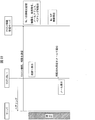
- FIG. 14 is a diagram showing a sequence of operations of the server 50 and six client devices (including client devices 100a to 100d) in the content transmission system shown in FIG.
- client No. 1 when one client device 100d (hereinafter referred to as client No. 1) of the six client devices paired with the server 50 has the viewing right, the other one client Consider a case where a viewing request is transmitted from the device 100c (hereinafter referred to as client No. 2) to the server 50.
- client No. 2 the device 100c
- the remaining four client devices are assigned client numbers. Called 3-6.
- the time notification unit of the server 50 that has received the viewing request from the client 2 receives the client number. 2 for client no. 1 that the content is being viewed, and the client No. 1 is notified of the time at which viewing of content ends.
- the notification time may be any time that allows the user to recognize the timing at which content can be received, and is not limited to the viewing end time.
- Client No. 2 shows the client No. 2 notified from the server 50. 1 displays the time when content viewing ends.
- Client No. 2 has a client No. 1 confirms the time when the content viewing ends, and determines the reserved time (viewing start time) for viewing the content in the time zone after that time. Client No. 2 notifies the server 50 of the reservation time determined by the user. It should be noted that the client No. It may be requested to watch after 1.
- the reservation part of the server 50 is the client No. 2 is notified of the reservation time, the client No. After the viewing time of the content according to 1, it is confirmed whether there is already a reservation for viewing the content by another client. Client No. 1, after the viewing time of the content by the client 1, if the reservation for viewing the content by another client has already been made, the reservation unit of the server 50 displays the client no.
- the reservation time determined by the user 2 is the client number. In addition to the content viewing time according to 1, it is checked whether the content viewing reservation time by another client is not batted.
- the reservation time determined by the user 2 is the client number. 1 does not overlap with the viewing time of the content by other clients and the viewing time of the content by other clients, the reservation unit of the server 50 receives the client number. 2 is notified that the acceptance of the reservation has been completed.
- the reservation part of the server 50 is the client No. 3 to 6, client No. 2 is notified of the time when viewing of the content according to 2 starts.
- the reservation unit of the server 50 has a client No. 1 to client No. 1 after the content viewing by the client No. 1 is finished. 2 that there is a reservation for viewing content.
- the reservation part of the server 50 is the client number. 2 is notified that content viewing is permitted.
- Client No. that received the notification from the server 50 2 requests the server 50 for a content list (at least one of a list of live contents and a list of recorded contents).
- Client No. 2 displays the content list received from the server 50.
- Client No. The second user designates (lists up, selects and determines) the content to be viewed from the displayed content list.
- Client No. 2 notifies the server 50 of the content designated by the user.
- the reservation part of the server 50 is the client No. 2 for client no.
- the content designated by the user 2 is transmitted.
- Client No. 2 outputs the content received from the server 50.
- client No Although the content designation is accepted after the content viewing in 1 is finished, it may be accepted at a timing before this.
- FIG. 15 is an outline of a content transmission system according to this reference example.
- the content transmission system illustrated in FIG. 15 is different from the content transmission system illustrated in FIG. 7 in that a server 60 is provided instead of the server 20.
- the server 60 has the same configuration as that of the server 20, but as described below, is different from the server 20 in that the function of the control unit 2 is further added.
- the information processing apparatus (server 60) according to the present reference example 1-5 is the content processing apparatus in the information processing apparatus according to the reference example 1-1 in a state where the number of registered devices simultaneously receiving the content has reached the upper limit. Is received by another registered device having a lower priority than the registered device that transmitted the viewing request, or there is a content having a lower priority than the content related to the viewing request. If it is received by another registered device, it further includes a priority control unit that transmits content to the registered device that has transmitted the viewing request instead of the other registered device.
- first user a user of a certain client
- second user wants to watch the live content.
- the second user feels that viewing of live content that can only be viewed now should be given priority.
- parents should watch content preferentially over children.
- the client device paired with the server 60 is given a priority order regarding the right to view the content in advance.
- the priority control unit of the server 60 receives a viewing request from a client device having a higher priority than the client device having the content viewing right
- the priority requesting unit requests the client having the content viewing right from the client device having a higher priority. Notify that you have received. Then, the right to view the content is switched to a client device having a higher priority.
- the server 60 when the server 60 receives a viewing request from a client having a lower priority than the client device having the content viewing right, the server 60 has received a viewing request from another client device to the client device having the content viewing right. To be notified. However, viewing rights are not switched.
- the priority order of clients is not limited to the priority order regarding viewing rights.
- a client device that desires to view live content may be given priority over a client device that desires to view recorded content.
- the server 60 transfers the viewing right to the other client device.
- the server 60 when the server 60 is transmitting content to the client device 100d (1), when a viewing request is received from the client device 100c (2), the client device 100c has priority over 100d. Is higher, the priority control unit of the server 60 requests the client device 100d having a lower priority to stop receiving (3). When the client device 100d responds to this request, the priority control unit of the server 60 starts transmitting content to the client device 100c (5). Thereby, the user of the client device 100c can start viewing desired content promptly.
- FIG. 16 is a diagram showing a sequence of operations of the server 60 and six client devices (including client devices 100a to 100d) in the content transmission system shown in FIG.
- client No. 1 when one client device 100d (hereinafter referred to as client No. 1) of the six client devices paired with the server 60 has the viewing right, the other one client An example in which a viewing request is transmitted from the device 100c (hereinafter referred to as client No. 2) to the server 60 will be described.
- the remaining four client devices are assigned client numbers. Called 3-6.
- client No. 1 the recorded content is viewed.
- FIG. 2 transmits a viewing request to the server 60.
- Client No. The priority control unit of the server 60 that receives the viewing request from the client 2 receives the client number. 2 for client no. 1 notifies that the content is being viewed.
- Client No. that received the notification from the server 60 2 requests the server 60 for a broadcast program list (a list of recorded broadcast programs and a live content list which is a list of programs being broadcast).
- a broadcast program list (a list of recorded broadcast programs and a live content list which is a list of programs being broadcast).
- the priority control unit of the server 60 is the client No. 2 in response to a request from the client No. 2 2 to send.
- Client No. 2 displays a broadcast program list received from the server 60.
- Client No. 2 designates one of the programs from the broadcast program list. Here, it is assumed that a live program is designated. Client No. 2 notifies the server 60 of the live program designated by the user.
- the priority control unit of the server 60 is the client No. 2 is confirmed to be a live program, not a recorded program. 1 is notified that a request for viewing a live program has been received, and requests that viewing of recorded content be stopped (viewing rights are abandoned). In other words, in this example, the priority control unit of the server 60 receives the client No. requesting live content. 2 is the client No. receiving the recorded content. It is determined that the priority is higher than 1.
- Client No. 1 displays that the server 60 has received a request to view a live program and that it is desired to stop viewing recorded content.
- Client No. The first user confirms the display and stops viewing the recorded content.
- Client No. 1 notifies the server 60 that it understands that the viewing right is abandoned.
- the priority control unit of the server 60 is the client No. 1, after receiving notification that the viewing right is to be waived, 2 is notified that viewing of the live program is permitted (viewing right is given).
- the priority control unit of the server 60 is a client No. 2 that the viewing right is given to the client No. 2 Notify 3-6.
- the priority control unit of the server 60 is the client No. 2 shows the contents of the live program designated by the user No. 2 to send.
- Each unit (notification unit, information transmission unit, reservation unit, time notification unit, priority control unit) of the control unit 2 of the servers 20 to 60 according to the reference examples 1-1 to 1-5 is an integrated circuit (IC chip) or the like. It may be realized by a logic circuit (hardware) formed in the above, or may be realized by software using a CPU (Central Processing Unit).
- IC chip integrated circuit
- CPU Central Processing Unit
- the servers 20 to 60 include a CPU that executes instructions of a program that is software that realizes each function, and a ROM (Read Only Memory) in which the program and various data are recorded so as to be readable by the computer (or CPU).
- a storage device (these are referred to as “recording media”), a RAM (Random Access Memory) for expanding the program, and the like are provided. Then, when the computer (or CPU) reads the program from the recording medium and executes it, the object of the invention according to the reference examples 1-1 to 1-5 is achieved.
- a “non-temporary tangible medium” such as a tape, a disk, a card, a semiconductor memory, a programmable logic circuit, or the like can be used.
- the program may be supplied to the computer via an arbitrary transmission medium (such as a communication network or a broadcast wave) that can transmit the program.
- the inventions according to the reference examples 1-1 to 1-5 can also be realized in the form of data signals embedded in a carrier wave, in which the program is embodied by electronic transmission.
- a mobile terminal configured in accordance with the guidelines of DLNA (Digital Living Network Alliance: registered trademark) can view images of a television (server) configured in accordance with the same guidelines at home.
- the server transmits the content wirelessly, and the client device receives the content at various locations in the home.
- a technology has also been developed that enables a client device paired with a server to receive content from the server outside the home.
- a client device outside the home can connect to the server indefinitely, that is, if the user can view the content outside the home for an indefinite period of time, the content is illegally used on a device other than the client device. May be watched. Therefore, it has been proposed to set a pairing expiration date, which is a period during which pairing is effective, that is, a time limit during which the client device can connect to the server, to the client device.
- the user of the client device does not necessarily know the pairing expiration date.
- a user who does not know the pairing expiration date feels that the content cannot be viewed suddenly when the pairing expiration date has passed. Therefore, it may be possible to notify the client device that the pairing expiration date is approaching.
- the server By placing the warning message in communication with the viewing application, the warning message can be transmitted to the client device relatively easily.
- the server 20 when communication between the server 20 and the client devices 100a to 100d (see FIG. 2) whose pairing expiration date is approaching is impossible, the server 20 has the client devices 100a to 100d.
- a method for notifying the above user of a warning message to the effect that the following pairing expiration date is approaching will be described by a method other than communication.
- the server 20 displays a screen on the server side. Display a warning message.
- the server 20 according to the reference example 2-1 has the same configuration as the server 1 described in the first and second embodiments. That is, the server 20 includes a control unit 2, a storage unit 3, a communication unit 4, a display unit 5, an input unit 6, and a content memory 7 (see FIG. 1). However, as described below, the function of the control unit 2 is different from that of the above embodiment.
- the information processing apparatus (server 20) according to Reference Example 2-1 is a content transmission system that transmits content to a registered device in response to a viewing request from a registered device (client devices 100a to 100d) registered in advance.
- An information processing apparatus that manages registration of the registered device, and notifies the user of the registered device that the period until the registration expiration date (pairing expiration date) of the registered device has reached a predetermined period Is included in the control unit (2).
- the notification unit when the notification unit cannot communicate with a registered device whose registration period has reached a predetermined period, the notification unit notifies the information processing apparatus. Accordingly, even when communication with the registered device is not possible, it becomes possible for the user of the registered device to recognize that the period until the expiration date of registration has reached the predetermined period.
- FIG. 17 is a diagram illustrating an operation sequence of the server 20 and the six client devices (including the client devices 100a to 100d) in the content transmission system of this reference example.
- one client device 100d out of the six client devices paired with the server 20 is assigned a client number. 1 and the other client device 100c is assigned a client number. Call it 2. The remaining four client devices are assigned client numbers. Called 3-6.
- the notification unit of the server 20 displays the client No. Try to send a warning message to 1.
- client No. 1 can receive a warning message from the server 20.
- the notification unit of the server 20 sends a warning message to the client number. 1 to send.
- the client No. that received the warning message from the server 20 1 displays the received warning message.
- the client No. 1 if content is being displayed, a warning message may be superimposed on the display of the content, or a warning message may be displayed prominently near the display of the content.
- Client No. 1 when the content is being viewed or the viewing application is main and operating (that is, when the content is being viewed with the viewing application), the client No. 1 displays a warning message superimposed on the content display. Alternatively, a warning message may be displayed so as to stand out in the vicinity of the content display.
- client No. 1 when the content is not being viewed, the client No. 1 displays specific contents (a date and time of a pairing expiration date, a reconnection (repairing) method, and a message that reconnection is possible only at home) in a dialog. If the viewing application is resident and does not operate in the main, the client No. 1 may alert the user by displaying an icon or the like that warns that the pairing expiration date is approaching.
- the notification unit of the server 20 is the client number. 2 to 6, all client numbers are assigned to client devices that can communicate with the server 20. Notify 1 to 6 connection expiration date.
- the client devices that have received the notification from the server 20 are all client numbers. Displays the connection expiration date 1-6.
- client no. 2 when the predetermined period is reached until the pairing expiration date, the notification unit of the server 20 receives the client number. 2 to send a warning message.
- client No. 2 is not in the activated state (that is, in the stopped state) and cannot receive a warning message from the server 20.
- Client No. 2 cannot send a warning message to the server 20, the notification unit of the server 20 receives the client number.
- a warning message indicating that the predetermined period has expired until the pairing expiration date 2 is displayed on the screen (display unit 5) of the server 20.
- the server 20 may display a warning message superimposed on the television display screen.
- the notification unit of the server 20 may display a simple icon or may display a simple message (word) such as “There is a client whose pairing expiration date is almost expired”. Further, the date and time of the pairing expiration date, the client model number, the user name, and the like may be displayed. These may be displayed in stages. In this configuration, the notification unit of the server 20 displays an icon and displays a simple message when an operation for specifying the icon is accepted. Further, when an operation for designating the message is accepted, a detailed explanation regarding the pairing expiration date is displayed.
- the notification unit of the server 20 may display a warning message when the server 20 is powered on (timing).
- the warning message may always be displayed from the time when the remaining period of 2 becomes a predetermined period.
- a warning message may be displayed periodically.
- the client No. It can be recognized that the pairing expiration date of 2 is approaching. As a result, the user can change the client No. 2 pairing by itself, client no. 2 users can be prompted to pair. In this way, the server 20 receives the client number. It is possible to prevent the pairing expiration date of 2 from being expired.
- a notification message is sent to the other client devices 100a to 100d that can communicate. Send.
- the user of the client device paired with the same server 20 is often a family, there is a high possibility that there is a user of another client device near the user of a certain client device. Therefore, the user of the client device whose pairing expiration date is approaching tells the other user who owns the client device paired with the same server 20 that the pairing expiration date of his client device is approaching. I can get it.
- the notification unit of Reference Example 2-2 cannot communicate with a registered device whose registration period has reached a predetermined period, it notifies other registered devices. Accordingly, even when communication with the registered device is not possible, it becomes possible for the user of the registered device to recognize that the period until the expiration date of registration has reached the predetermined period.
- FIG. 18 is a diagram illustrating an operation sequence of the server 20 and the six client devices (including the client devices 100a to 100d) in the content transmission system of the present reference example.
- one client device 100d out of the six client devices paired with the server 20 is assigned a client number. 1 and the other client device 100c is assigned a client number. Call it 2. The remaining four client devices are assigned client numbers. Called 3-6.
- the notification unit of the server 20 displays the client number. Try to send a warning message to 1.
- client No. 1 can receive a warning message from the server 20.
- the notification unit of the server 20 sends a warning message to the client number. 1 to send.
- Client No. 1 displays a warning message received from the server 20.
- the reference example Since this is the same as described in 2-1, the description thereof is omitted.
- client no. 2 the notification unit of the server 20 receives the client No. 2 to send a warning message.
- client No. 2 is not in an activated state and cannot receive a warning message from the server 20.
- Client No. 2 cannot transmit a warning message, the notifying unit of the server 20 receives another client number. 1, 3 to 6, a client No. 1 is connected to a client device that can communicate with the server 20. A warning message indicating that the pairing expiration date of 2 is approaching is transmitted.
- the notification unit of the server 20 displays an icon, a simple message, and a client number in addition to the warning message. 2 at least one of the detailed information of the client No. 1, 3 to 6 may be transmitted.
- the notification unit of the server 20 is a client No. 1, 3 to 6, the client No.
- the pairing expiration date of 1, 3 to 6 or the remaining period until the pairing expiration date is also notified.
- Client No. 1 and 3 to 6 display the pairing expiration date notified from the server 20 or the remaining period until the pairing expiration date. Therefore, client no.
- the users 1, 3 to 6 can know not only that the pairing expiration date of the client 2 is approaching, but also information related to the pairing expiration date of their own client.
- the notification unit of Reference Example 2-3 if the notification unit of Reference Example 2-3 cannot communicate with a registered device whose registration period has reached a predetermined period, the notification unit waits until communication with the registered device becomes possible, and can communicate with the registered device. The registered device is notified. This makes it possible for the user of the registered device to recognize that the period until the expiration date of registration has reached a predetermined period in a case where communication with the registered device is temporarily disabled.
- FIG. 19 is a diagram illustrating an operation sequence of the server 20 and two client devices (client devices 100c to 100d) in the content transmission system of the present reference example.
- one client device 100d of the two client devices paired with the server 20 is set as the client number. 1 and the other client device 100c is assigned a client number. Call it 2.
- the notification unit of the server 20 receives the client number. Try to send a warning message to 1.
- client No. 1 can receive a warning message from the server 20.
- the notification unit of the server 20 sends a warning message to the client number. 1 to send.
- Client No. 1 displays the warning message received from the server 20 on the screen.
- the details are as described in the reference example 2-1, and the description thereof is omitted.
- client no. 2 when the period until the pairing expiration date becomes a predetermined period, the notification unit of the server 20 receives the client number. 2 to send a warning message.
- client No. 2 is not in an activated state and cannot receive a warning message from the server 20.
- Client No. 2 cannot send a warning message to the server 20, the notification unit of the server 20 receives the client number. 2. Wait for communication between the server 2 and the server 20 to be possible.
- Client No. 2 when in the activated state, notifies the server 20 that it has been activated. At this time, the client No. 2 may be notified to the server 20 of address information (for example, an address in the home LAN) for transmitting the message.
- address information for example, an address in the home LAN
- Client No. 2 and the server 20 can communicate with each other, the notification unit of the server 20 receives the client number. 2 for client no. A warning message indicating that the pairing expiration date of 2 is approaching is transmitted. Client No. 2 displays the warning message received from the server 20 on the screen.
- warning message is transmitted when a client device that has not been started up.
- this application software is used.
- a warning message may be transmitted when is running.
- the notification unit of the server 20 is a client No. 2 and a client message No. 2 1 may be displayed on the screen of the server 20, or the client number. 2 may be displayed. This is because when it is found that the pairing deadline of a certain device is close, there are many users who are concerned about the pairing deadline of another device.
- the server 20 notifies the client device that the pairing expiration date is approaching. However, if the server 20 is in a stopped state, it cannot communicate with the client device and cannot receive a notification from the server 20. In addition, a client device in an environment that cannot communicate with the server 20 cannot receive a notification from the server 20.
- the client device manages the pairing expiration date of the client device, and when the pairing expiration date approaches, the client device user is notified that the pairing expiration date is approaching.
- the configuration for notification will be described. That is, in Reference Example 2-4, the registered devices (client devices 100a to 100d) include a notification unit that notifies that the period until the registration expiration date (pairing expiration date) has reached a predetermined period. An example will be described.
- the client devices 100a to 100d have the same configuration as the server 1. That is, the client devices 100a to 100d include a control unit, a storage unit, a communication unit, a display unit, an input unit, and the like (see FIG. 1).
- the control units of the client devices 100a to 100d include a notification unit that notifies the device that the pairing expiration date is approaching.
- the server 20 when pairing with the client devices 100a to 100d, transmits the pairing expiration date of the client devices 100a to 100d to the client devices 100a to 100d.
- the notification units of the client devices 100a to 100d store and manage the pairing expiration date received from the server 20. When a predetermined period is reached until the pairing expiration date, the notification units of the client devices 100a to 100d display a preset warning message.
- the server 20 cannot communicate with the client devices 100a to 100d, the user of the client devices 100a to 100d can be notified that the pairing expiration date is approaching.
- FIG. 20 is a diagram illustrating an operation sequence of the server 20 and the two client devices 100c and 100d in the content transmission system according to the present reference example.
- the client device 100d is assigned a client number. 1
- the client device 100c is assigned a client number. Call it 2.
- Client No. 1 and client no. 2 the server 20 notifies the pairing expiration date in advance.
- Client No. 1 and client no. 2 stores the notified pairing expiration date in a storage unit (not shown).
- the server 20 is in a stopped state throughout the sequence. 1 and client no. It is assumed that communication with 2 is impossible.
- Client No. The 1 notification unit monitors the period until the pairing expiration date. When the predetermined period is reached until the pairing expiration date, the client No. No. 1 notification unit displays a preset warning message. In addition, client No. 2 also monitors the period until the pairing expiration date. Client No. 2 is the client number. Similar to 1, a warning message is displayed when a predetermined period of time elapses until the pairing expiration date.
- the client device has a configuration that can notify the user of the client device that the pairing expiration date is approaching even when the warning receiving application is not activated. explain.
- the notification unit of the server 20 when the notification unit of the server 20 performs pairing with the client devices 100a to 100d, the pairing expiration date of the client devices 100a to 100d is stored in a storage device (not shown). And the notification part of the server 20 transmits the warning message about the client apparatus which became the predetermined period until the pairing expiration date by an electronic mail (henceforth abbreviated as mail).
- the mail address is stored in advance at the time of pairing.
- the user can receive a warning message if there is a terminal that can be connected to the Internet (in the case of web mail). Further, the user does not have to start up the warning receiving application. Further, since the user generally checks the mail frequently, it is easy to notice that the user has received the warning message mail.
- the means for the server 20 to send a warning message to the client devices 100a to 100d is not limited to email.
- the server 20 may send a warning message to the client devices 100a to 100d using another means via the Internet. That is, the warning message may be uploaded on a network that can be browsed by the user of the client device, or the warning message may be transmitted by communication means other than mail.
- the notifying unit of Reference Example 2-5 makes information indicating that the period until the expiration date of registration has reached a predetermined period accessible from the registered device via a predetermined communication network. This makes it possible for the user of the registered device to recognize that the period until the expiration date of registration has reached a predetermined period even when communication with the registered device is not possible.
- FIG. 21 is a diagram illustrating a sequence of operations of the server 20 and the client devices 100c and 100d in the content transmission system according to the present reference example.
- the client device 100d is assigned a client number. 1
- the client device 100c is assigned a client number. Call it 2.
- client No. 1 the warning receiving application is in a stopped state, and the client No. 1, it is assumed that a warning message cannot be received from the server 20.
- the notification unit of the server 20 transmits a warning message to a preset mail address.
- the second user confirms the warning message using the application software for browsing electronic mail. As a result, the user can change the client No. It can be recognized that the pairing expiration date of 2 is approaching.
- Reference Example 2-6 In Reference Example 2-5, the configuration in which the server 20 transmits a warning message mail to a predetermined mail address via the Internet has been described. However, if the server 20 is turned off or the server 20 cannot connect to the Internet for some reason, the server 20 cannot send a warning message mail.
- the server 20 when the server 20 performs pairing with the client devices 100a to 100d, the pairing expiration date of the client devices 100a to 100d, the client information for identifying the client devices 100a to 100d, and the client devices 100a to 100d
- the mail address associated with the 100d client information is transmitted to the client information management server, which is another server connected to the Internet.
- the client information includes, for example, the model names of the client devices 100a to 100d and the user names of the client devices 100a to 100d.
- the client information management server manages the pairing expiration date of the client devices 100a to 100d. Then, the client information management server transmits a warning message by e-mail to the e-mail address associated with the device that has reached a predetermined period until the pairing expiration date. That is, in Reference Example 2-6, an example will be described in which the client information management server includes a notification unit that notifies that the period until the registration expiration date (pairing expiration date) has reached a predetermined period.
- the client information management server has the same configuration as the server 1. That is, the client information management server includes a control unit, a storage unit, a communication unit, a display unit, an input unit, and the like (see FIG. 1).
- the control unit of the client information management server includes the notification unit.
- the user can open the mail on the client device and check the warning message. . If the mail is a web mail, the user can receive a warning message at a terminal that can be connected to the Internet even when the client devices 100a to 100d are not at hand.
- the means for the client information management server to send a warning message to the client devices 100a to 100d is not limited to email.
- the client information management server may send a warning message to the client devices 100a to 100d using another means via the Internet or the like.
- FIG. 22 is a diagram illustrating a sequence of operations of the server 20, the client device 100d, and the mail receiving server of the content transmission system of this reference example.
- the client device 100d is assigned a client number. Call it 1.
- the server 20 receives the client number. 1 pairing expiration date, client No. 1 client information and mail address are transmitted to the client information management server.
- the notification unit of the client information management server receives the client number received from the server 20. 1 pairing expiration date is managed. Then, the notification unit of the client information management server displays the client number. When the predetermined period of time until the pairing expiration date of 1 is reached, the client No. A warning message mail is transmitted to the mail address associated with the client information 1. As a result, the client No. 1 user can confirm the warning message by e-mail.
- the notification unit of the control unit 2 of the server 20 according to the reference examples 2-1 to 2-6 may be realized by a logic circuit (hardware) formed in an integrated circuit (IC chip) or the like, or a CPU ( It may be realized by software using a Central Processing Unit.
- the server 20 includes a CPU that executes instructions of a program that is software that realizes each function, a ROM (Read Only Memory) or a storage in which the program and various data are recorded so as to be readable by the computer (or CPU).
- a device (these are referred to as “recording media”), a RAM (Random Access Memory) for expanding the program, and the like are provided. Then, when the computer (or CPU) reads the program from the recording medium and executes it, the object of the invention according to the reference examples 2-1 to 2-6 is achieved.
- a “non-temporary tangible medium” such as a tape, a disk, a card, a semiconductor memory, a programmable logic circuit, or the like can be used.
- the program may be supplied to the computer via an arbitrary transmission medium (such as a communication network or a broadcast wave) that can transmit the program.
- the inventions according to Reference Examples 2-1 to 2-6 can also be realized in the form of a data signal embedded in a carrier wave, in which the program is embodied by electronic transmission. The same applies to the notification units included in the client devices 100a to 100d and the client information management server.
- pairing expiration date is too short (or too long)
- the user may forget to update the pairing expiration date.
- the user may notice that the pairing expiration date has expired when trying to use the client device without using the client device for a long time.
- pairing expiration date has expired when trying to use the client device without using the client device for a long time.
- there is a restriction that pairing is possible only via the home LAN pairing cannot be performed unless the user goes home once, which is very inconvenient. Therefore, in this reference example, a configuration for preventing pairing expiration will be described.
- the server 20 or the client devices 100a to 100d periodically Update the expiration date of pairing.
- pairing can be updated only from within the house. More specifically, the expiration date of pairing is updated by performing pairing again from home.
- the pairing update may be configured from outside the house.
- the server 20 according to the reference example 3-1 has the same configuration as the server 1 described in the first and second embodiments. That is, the server 20 includes a control unit 2, a storage unit 3, a communication unit 4, a display unit 5, an input unit 6, and a content memory 7 (see FIG. 1). However, as described below, the function of the control unit 2 is different from that of the above embodiment.
- the information processing apparatus (server 20) according to Reference Example 3-1 is a content transmission system that transmits content to a registered device in response to a viewing request from a registered device (client devices 100a to 100d) registered in advance.
- An information processing apparatus that manages registration of the registered device, and when the registered device is connected to the same local area network (home LAN) as the information processing device, the registration expiration date of the registered device (
- the control unit (2) includes an update unit that periodically updates (pairing expiration date). Note that the update unit may prompt the user to update, and in this case, the expiration date is updated only when the user agrees to update.
- the client devices 100a to 100d have the same configuration as the server 1. That is, the client devices 100a to 100d include a control unit, a storage unit, a communication unit, a display unit, an input unit, and the like (see FIG. 1).
- the control unit of the client devices 100a to 100d may include the update unit. In this case, the expiration date (pairing expiration date) is updated under the initiative of the client devices 100a to 100d.
- FIG. (A) and (b) of FIG. 23 are diagrams illustrating an operation sequence of the server 20 and the client device 100d of the content transmission system according to the present reference example.
- the client device 100d is assigned the client No. Call it 1.
- FIG. 23 is a sequence illustrating a pairing update method when the client device spontaneously updates pairing.
- the server 20 and client No. It is assumed that 1 is already paired.
- client No. 1 it is assumed that the server 20 has notified the pairing expiration date.
- client No. 1 moves from outside the house to the house (connected to the home LAN). Then, when a predetermined period (a period shorter than the pairing expiration date. For example, if the expiration date is three months, one week or one day) has passed since the last pairing, the client No. The update unit 1 transmits a pairing request to the server 20 and performs pairing with the server 20 again. Thereby, the pairing expiration date is reset. After pairing is completed, the client No. The update unit 1 terminates the connection with the server 20. This is because the connection for renewing the pairing is sufficient in a short time.
- a predetermined period a period shorter than the pairing expiration date. For example, if the expiration date is three months, one week or one day
- the update unit 1 may display a screen for selecting whether or not pairing can be updated, and may transmit a pairing request when the user of the own device selects that updating is possible.
- the update unit 1 makes a pairing request to the server 20 as described above, and updates the pairing expiration date.
- FIG. 1 As shown in FIG. 1 is already paired with the server 20 and can communicate with the server 20 from outside the house (such as reception of content).
- Client No. moved to home 1 connects to a home LAN with WiFi (registered trademark).
- WiFi registered trademark
- the update unit of the server 20 receives the client number. 1 is transmitted to inquire whether or not to update the pairing expiration date.
- Client No. 1 notifies the server whether or not to update the pairing expiration date with the server 20. Note that the user can select whether or not to update.
- Client No. 1 notifies that the pairing expiration date is to be updated, the update unit of the server 20 receives the client number. Pair with 1 again to update the pairing expiration date. After pairing is completed, the client No. 1 ends the connection with the server 20 (WiFi connection). Client No. 1 notifies that the pairing expiration date is not updated, the update unit of the server 20 receives the client number. The pairing expiration date of 1 is not updated.
- the update unit of the server 20 will receive the client number as described above. 1 confirms whether pairing is necessary.
- the information processing apparatus (server 20) according to the present reference example 3-2 is the information processing apparatus according to the reference example 3-1.
- the control unit (2) The time limit for viewing content by the registered device is updated when the viewing time limit (pairing expiration date) is less than a predetermined period.
- the server 20 or the client devices 100a to 100d updates the expiration date of pairing.
- the updating unit of Reference Example 3-2 performs registration when the registered devices (client devices 100a to 100d) are connected to the same local area network (home LAN) as the information processing device (server 20).
- the expiration date of the registered device that has reached a predetermined period until the expiration date (pairing expiration date) is updated.
- This updating unit may be included in the control unit of the registered device (client devices 100a to 100d).
- the update unit may prompt the user to update, and in this case, the expiration date is updated only when the user agrees to update.
- FIGS. (A) and (b) of FIG. 24 are diagrams showing an operation sequence of the server 20 and the client device 100d of the content transmission system according to this reference example.
- the client device 100d is assigned the client No. Call it 1.
- the server 20 and the client No. 1 is already paired with the client No. 1, it is assumed that the server 20 has notified the pairing expiration date.
- FIG. 24 is a sequence for explaining a pairing update method when the client device voluntarily updates pairing. As shown in FIG. 1 is at home throughout the sequence.
- the update unit 1 transmits a pairing request to the server 20. Assuming that the user does not want to update, the client No.
- the update unit 1 may display a screen for selecting whether or not pairing can be updated, and may transmit a pairing request when the user of the own device selects that updating is possible.
- the client No. The update unit 1 terminates the connection with the server 20. Although not shown in the figure, the server 20 has a client No. 1 is notified of the pairing expiration date after the update.
- the update unit 1 transmits a pairing request to update pairing.
- the update unit of the server 20 has a client No. 1 is monitored, and the remaining period until the pairing expiration date is monitored. When the expiration date is approaching (before the predetermined period), the client No. 1 is requested to update pairing.
- the update unit of the server 20 receives the client number. Pair with 1 again to update the pairing expiration date. After pairing is completed, the client No. 1 ends the connection with the server 20.
- the update unit of the control unit 2 of the server 20 according to the reference examples 3-1 and 3-2 may be realized by a logic circuit (hardware) formed in an integrated circuit (IC chip) or the like, or a CPU ( It may be realized by software using a Central Processing Unit.
- the server 20 includes a CPU that executes instructions of a program that is software that realizes each function, a ROM (Read Only Memory) or a storage in which the program and various data are recorded so as to be readable by the computer (or CPU).
- a device (these are referred to as “recording media”), a RAM (Random Access Memory) for expanding the program, and the like are provided.
- the computer or CPU
- reads the program from the recording medium and executes it the object of the invention according to Reference Examples 3-1 and 3-2 is achieved.
- the recording medium a “non-temporary tangible medium” such as a tape, a disk, a card, a semiconductor memory, a programmable logic circuit, or the like can be used.
- the program may be supplied to the computer via an arbitrary transmission medium (such as a communication network or a broadcast wave) that can transmit the program.
- a transmission medium such as a communication network or a broadcast wave
- the inventions according to the reference examples 3-1 and 3-2 can also be realized in the form of a data signal embedded in a carrier wave, in which the program is embodied by electronic transmission. The same applies to the update units included in the client devices 100a to 100d.
- a device having a function of skipping reproduction of a CM included in recorded broadcast content is known.
- a CM skip function even when viewing broadcast content from outside the home in the content transmission system as described above. . This is because it is considered that there are many users who feel uncomfortable that CM skip is possible in the house but it is impossible outside the house.
- the content transmission system of the present reference example includes the server 20 and client devices 100a to 100d as in the other reference examples. That is, the server 20 according to this reference example is similar to the server 1 described in the first and second embodiments, the control unit 2, the storage unit 3, the communication unit 4, the display unit 5, the input unit 6, and the content memory 7. (See FIG. 1). However, as described below, the function of the control unit 2 is different from that of the above embodiment.
- the playback devices (client devices 100a to 100d) according to the reference example 4-1 are playback devices that play back content acquired by requesting the content transmission system, and change (skip) the playback position of the content being played back. And when the playback position is changed by the playback position changing unit so that the inserted content inserted in the content is not played back, the inserted content is changed to the content after the change of the playback position. And a playback unit for playback. Thereby, the inserted content (for example, CM) can be viewed while changing the reproduction position.
- CM for example, CM
- the band-like figure shown on the left side shows the configuration of the recorded content, and the horizontal direction in the figure shows time.
- the recorded content includes a program part and a CM part inserted into the program part.
- the reproduction position is indicated by an arrow, and an image displayed at the reproduction position is shown on the right side of the figure.
- the client device 100a reproduces the stored recorded content while decoding it.
- the client device may be any of 100a to 100d.
- the playback position is included in the program part, and the video of the television program is displayed on the screen of the client device.
- the playback position is the CM start position.
- the user performs a skip operation (including 30-second jump, fast forward, etc.) to skip the reproduction position. Then, the playback position changing unit of the client device 100a accepts this operation.
- the playback position changing unit of the client device 100a determines whether or not the skipped portion includes the CM portion when the skip operation is accepted. When the CM portion is not included, the playback position changing unit of the client device 100a plays back the recorded content from the playback position after skipping.
- the playback position changing unit of the client device 100a notifies the playback unit of information (for example, the CM start time and end time) indicating the skipped CM portion.
- the playback unit displays the skipped CM image on the sub-screen smaller than the main screen in the main screen displaying the video of the recorded content. That is, as shown on the right side of FIG. 25C, the CM is displayed with PinP (PicturePin Picture).
- the playback position changing unit of the client device 100a displays the recorded content played back from the playback position after skipping on the main screen.
- the client device 100a decodes both the CM portion and the program portion in parallel.
- the content transmission system of the present reference example includes the server 20 and client devices 100a to 100d as in the other reference examples.
- the client devices 100a to 100d according to this reference example include a control unit 2, a storage unit 3, a communication unit 4, a display unit 5, an input unit 6, and the like (see FIG. 1).
- the control units of the client devices 100a to 100d include the following acquisition unit and playback unit.
- the playback devices (client devices 100a to 100d) according to Reference Example 4-2 are playback devices that play back the content acquired by requesting the content transmission system, and the content being played back includes the inserted content (CM).
- the server 20 according to the reference example 4-2 has the same configuration as the server 1. That is, the server 20 includes a control unit 2, a storage unit 3, a communication unit 4, a display unit 5, an input unit 6, and a content memory 7 (see FIG. 1).
- the control unit of the server 20 includes the following acquisition unit and transmission unit.
- the information processing apparatus (server 20) according to Reference Example 4-2 is an information processing apparatus that transmits content to a playback apparatus (client devices 100a to 100d) registered in advance in response to a viewing request.
- the content transmitted to the playback device includes an insertion content (CM)
- a transmission unit for transmitting to the apparatus As a result, it is possible to acquire the insertion content corresponding to the playback device or the user and play it instead of the default insertion content.
- FIG. 26 is a diagram illustrating an operation sequence of the server 20, the client device 100d, and the CM management server of the content transmission system according to the present reference example.
- the client device 100d is assigned the client No. Call it 1.
- the CM management server is a server that manages, for each sponsor, CM contents corresponding to user information such as age, sex, and residential area.
- Client No. 1 requests the server 20 to transmit content after pairing with the server 20 is completed.
- the transmission unit of the server 20 sends the requested content to the client number. 1 to send. Further, the acquisition unit of the server 20 specifies the sponsor of the content transmitted by the transmission unit.
- client No. 1 starts playback of the content received from the server 20, and the client No. 1 1 acquires the client number. 1 user information (age, gender, user location information, etc.) is transmitted to the server 20.
- the acquisition unit of the server 20 notifies the CM management server of the received user information and the identified sponsor, and searches for the user's preference of the user information among the CM contents of the sponsor.
- the CM management server searches for the CM content based on this request. For example, client No. CM content corresponding to a region such as a store close to the position of one user may be selected.
- the CM management server transmits the CM information indicating the content of the detected CM content and the moving image data which is the main body of the CM content to the server 20, and the transmission unit of the server 20 transmits the moving image data to the client No. 1 to send.
- the first playback unit decodes the received moving image data of the CM content and stores it in a buffer different from the content being output.
- the output buffer Switch When the playback position of the content enters the playback range of the CM, the output buffer Switch. As a result, the received CM content is replaced with the original CM and output.
- the CM content is replaced according to the user information.
- the replaced CM content may be specified without using the user information. For example, it is not necessary to use user information for replacement with the latest CM content.
- control blocks (particularly the reproduction position changing unit, the acquisition unit, and the reproduction unit) of the client devices 100a to 100d according to the reference examples 4-1 to 4-2 and the control blocks (particularly the acquisition unit and the transmission unit) of the server 20 are Alternatively, it may be realized by a logic circuit (hardware) formed in an integrated circuit (IC chip) or the like, or may be realized by software using a CPU (Central Processing Unit).
- a logic circuit hardware
- IC chip integrated circuit
- CPU Central Processing Unit
- the client devices 100a to 100d and the server 20 include a CPU that executes instructions of a program that is software that realizes each function, and a ROM (the above-described program and various data are recorded so as to be readable by a computer (or CPU)).
- a computer or CPU
- Read Only Memory or a storage device (these are referred to as “recording media”), a RAM (Random Access Memory) for expanding the program, and the like.
- a “non-temporary tangible medium” such as a tape, a disk, a card, a semiconductor memory, a programmable logic circuit, or the like can be used.
- the program may be supplied to the computer via an arbitrary transmission medium (such as a communication network or a broadcast wave) that can transmit the program.
- the inventions according to the reference examples 4-1 to 4-2 can also be realized in the form of a data signal embedded in a carrier wave, in which the program is embodied by electronic transmission.
- the information processing apparatus (server 1) is configured to request registration of a device in a content transmission system that transmits content to a registered device in response to a request from a registered device registered in advance (pairing).
- a cancellation candidate selection unit that selects a cancellation candidate that is a candidate for canceling registration from registered devices when a registration request is received in a state where the number of registered devices has reached the upper limit.
- Airing management unit 11 and a candidate presenting unit (Pairing management unit 11) for presenting the cancellation candidates to the user and selecting whether or not to cancel the cancellation candidate registration (pairing cancellation).
- a cancellation candidate is selected from the registered devices and presented to the user, and the cancellation candidate is registered. Select whether to cancel. Therefore, it is possible to easily select an appropriate device as an object of deregistration as compared with a case where a device to be deregistered is selected from all registered devices.
- the user who is the candidate for presenting the cancellation candidate may be a user who has made a new registration request, or may be another user (for example, a user who has the authority to cancel registration).
- the presentation target is a user who has made a new registration request, it may be presented by a device that has made a new registration request, or may be presented by another device (for example, a content transmission device).
- the content transmission apparatus (server 1) that transmits content to the registered device is a local area network (home LAN) to which the content transmission apparatus is connected.
- a device detection unit (position determination unit 13) that detects a device or a registered device at a connectable position is provided, and the release candidate selection unit selects a release candidate from among the registered devices detected by the device detection unit.
- the above configuration is selected as a cancellation candidate from registered devices connected to the local area network or registered devices at connectable locations. This is effective, for example, when registration is accepted only from a device connected to the local area network. This is because even if the registration of the device contrary to the intention of the user is canceled, it can be re-registered immediately.
- the above configuration is effective when, for example, a device connected to a local area network can receive content from a content transmission device without performing registration. This is because even if the registration is canceled, the state in which the content can be received does not change.
- the information processing apparatus is the information processing apparatus according to aspect 2, wherein the registered device specifies the accumulated time connected to the local area network or the accumulated time at a connectable position. (Residential residence time specifying unit 14), and the cancellation candidate selection unit preferentially releases registered devices having a longer cumulative time specified by the residence time specifying unit among the registered devices detected by the device detection unit.
- Registered devices that have a longer cumulative time connected to the local area network or a longer cumulative time at a connectable location are mainly used within the local area network, and are not sufficient for receiving content from outside the local area network. There is a high possibility that it is not used. Therefore, according to the above configuration, a registration device that is highly likely not to be used for receiving content from outside the local area network and is appropriate to be released can be set as a release candidate. In addition, it is possible to prevent devices that have not been used for viewing content from outside the local area network from being registered for a long time.
- the frequency specifying unit that specifies the frequency at which the registration device requests the content transmission apparatus from outside the local area network and acquires the content.
- the cancel candidate selecting unit gives priority to a registered device with a lower frequency specified by the frequency specifying unit as a cancel candidate.
- registered devices with lower frequency of content acquisition from outside the local area network are given priority as cancellation candidates. Therefore, a registered device that is less frequently used for receiving content from outside the local area network and is appropriate to be released can be set as a release candidate.
- the content transmission apparatus that transmits content to the registered device is connected to a local area network to which the content transmission apparatus is connected. And a device capable of transmitting content to a device that communicates with the content transmission device via an external communication network.
- the information processing device is configured such that the registered device is connected from the content transmission device outside the local area network.
- a non-reception period specifying unit that acquires non-reception period information indicating a period in which content is not received is provided, and the cancellation candidate selection unit is registered based on the non-reception period information for a longer period in which no content is received Prioritize equipment as a candidate for release.
- a registered device having a longer period of not receiving content from the content transmission apparatus outside the local area network is given priority as a cancellation candidate. Therefore, registered devices that have a long period of not receiving content from the content transmission apparatus outside the local area network and are appropriate to be released can be set as cancellation candidates.
- the period may be the most recent non-reception period (elapsed time since the last reception) or the cumulative non-reception period.
- the information processing apparatus is the information processing apparatus according to any one of the aspects 1 to 5, wherein the accumulated usage time obtained by accumulating the time when the registered device is used in a predetermined mode, or the registered device is in a predetermined mode.
- a usage status identifying unit that identifies a usage frequency that has been used, and the cancellation candidate selecting unit includes a registered device with a shorter cumulative usage time identified by the usage status identifying unit or a registered device with a lower usage frequency. Priority is given to cancellation candidates.
- the predetermined mode may be a usage mode of content reception, or may be another usage mode such as displaying an image on a device.
- the information processing apparatus is the information processing apparatus according to any one of aspects 1 to 6, wherein the registration request source device has a higher registration priority than the registered device according to a predetermined criterion.
- a priority determination unit that determines whether the registration request is lower, and the candidate presentation unit determines that the priority of the registration request is lower than that of the registered device. Then, the determination result is notified to the user to select whether or not the registration request can be canceled.
- the cancellation candidate is selected from the registered devices, but there may be a case where the registered device that is registered earlier should give priority to the registration device than the device that has transmitted the registration request. Therefore, according to the above configuration, when it is determined that the registration request source device has lower registration priority than the registered device, the determination result is notified to the user, and the registration request is canceled. Select whether or not. Therefore, in order to register a device with a low priority, it is possible to prevent the registration of a device with a high priority from being canceled.
- the information processing apparatus may be realized by a computer.
- a control program for the processing apparatus and a computer-readable recording medium on which the control program is recorded also fall within the scope of the present invention.
- the present invention can also be expressed as follows.
- the remote viewing compatible device (base unit) has a list of paired remote viewing terminals (hereinafter referred to as slave units), and if the number of slave units has reached the upper limit when receiving a pairing request, a pairing request is made Out of paired handsets and the handset that has not been paired to fit within the above upper limit range (does not accept the request from the handset that is currently requesting pairing or has been paired (Cancel pairing of slave unit)
- the remote viewing compatible device has means for acquiring whether the slave is in the house or outside the home, and whether the pairing requesting slave and the paired slave are in the house or not. In accordance with the detection result, there is a change in the determination method for determining a child device candidate that is not paired from the child device that is requesting pairing and the paired child device.
- the remote viewing-compatible device includes a slave unit that exists outside the home, a slave unit that exists outside the home, and a slave unit that is present in the home among all the slave units including the slave unit that is requesting pairing and the paired slave unit. If there is, pairing is canceled in preference to the paired slaves in the house.
- the remote viewing-compatible device has means for acquiring the time during which the paired child device has been continuously present in the home, and the paired child devices existing in the home are not present in the home. The longer the time, the higher the priority for the pairing cancellation candidate.
- the remote viewing compatible device has means for acquiring the frequency of remote viewing performed on the paired slave unit, and if the paired slave unit does not exist in the home, the pairing that is outside the home Cancel pairing by giving priority to remote handsets with low remote viewing frequency.
- the present invention can be used in a content transmission system that transmits content to a registered device.
Landscapes
- Engineering & Computer Science (AREA)
- Signal Processing (AREA)
- Computer Networks & Wireless Communication (AREA)
- Multimedia (AREA)
- Two-Way Televisions, Distribution Of Moving Picture Or The Like (AREA)
- Information Transfer Between Computers (AREA)
Abstract
Description
以下、本発明の実施の形態について、詳細に説明する。まず、図2に基づいて、本実施形態に係るコンテンツ送信システムの概要を説明する。図2は、コンテンツ送信システムの概要を示す図である。
次に、サーバ1の構成を図1に基づいて説明する。図1は、サーバ1の要部構成を示すブロック図である。図示のように、サーバ1は、制御部2、記憶部3、通信部4、表示部5、入力部6、およびコンテンツメモリ7を備えている。
続いて、ペア機器管理情報の詳細を図3に基づいて説明する。図3は、ペア機器管理情報の一例を示す図である。図示のペア機器管理情報は、機器IDと、通信アドレスと、宅内存否を示す情報と、宅内滞留時間を示す情報と、宅外からのコンテンツ取得頻度を示す情報とが対応付けられたテーブル形式の情報である。
次に、サーバ1が実行するペアリング処理の流れを図6に基づいて説明する。図6は、ペアリング処理の一例を示すフローチャートである。なお、同図の処理は、クライアント機器からのペアリング要求の受信を契機として開始される。また、サーバ1は、ペアリング要求と共に、クライアント機器の機器IDを受信しているとする。
上記実施形態では、下記(1)の基準で宅内に存在すると判定されたクライアント機器のうち、下記(2)の宅内滞留時間が最も長いクライアント機器を解除候補とする例を説明した。また、下記(1)の基準で宅内には存在しないと判定されたクライアント機器のうち、下記(3)の宅外からのコンテンツ取得頻度が最も低いクライアント機器を解除候補とする例を説明した。
(1)宅内存否(宅内のクライアント機器を優先して解除候補とする)
(2)宅内滞留時間(宅内滞留時間の長いクライアント機器を優先して解除候補とする)
(3)宅外取得頻度(宅外からのコンテンツ取得頻度が低いクライアント機器を優先して解除候補とする)
しかしながら、解除候補の選択は、必ずしも上記のような組み合わせで行う必要はない。例えば、(1)で宅内に存在すると判定されたクライアント機器を全て解除候補としてもよい。また、(1)の基準は用いずに、(2)または(3)の基準のみ、あるいはこれらの基準の組み合わせにより、解除候補を決定してもよい。さらに、(1)~(3)の全ての基準の組み合わせにより、解除候補を決定してもよい。
以上のようにして選択した解除候補ではあっても、ペアリング要求している機器の方がペアリングの優先度が低く、上記のような基準から判断して、ペアリング解除するよりも、ペアリング要求をキャンセルする方が妥当な場合がある。このような場合には、その旨をユーザに提示して、ペアリング要求のキャンセルの可否を選択させてもよい。これにより、優先度の低い機器とペアリングするために、優先度の高い機器のペアリングを解除してしまうことを防ぐことができる。
上記実施形態では、解除候補をユーザに提示して、最終的な解除の可否はユーザに選択させる例を説明したが、ユーザを介することなく、自動で解除候補のペアリングを解除してもよい。この場合、ペアリング管理部11は、上記のような基準に従って1つの解除候補を選択し、選択した解除候補のペアリングを解除して、代わりにペアリング要求の送信元の機器とペアリングさせる。
上記実施形態では、サーバ1がコンテンツの送信と、ペアリングの管理との両方を行う例を示したが、これらを個別の装置で行うようにしてもよい。例えば、コンテンツ要求を受信し、該要求に応じてコンテンツを送信するコンテンツ送信装置と、ペアリング要求を受信し、該要求に応じてペアリングする情報処理装置とを含むシステムであっても、サーバ1と同様の機能を実現できる。このようなシステムでは、解除候補の決定および提示のための処理を上記情報処理装置で行ってもよいし、コンテンツ送信装置で行ってもよい。
サーバ1の制御ブロック(特に制御部2)は、集積回路(ICチップ)等に形成された論理回路(ハードウェア)によって実現してもよいし、CPU(Central Processing Unit)を用いてソフトウェアによって実現してもよい。
図7~図8を用いて、本発明の一参考例を説明する。本参考例では、あるクライアント機器のユーザが、他のクライアント機器からの視聴要求(コンテンツ送信要求)があることを容易に認識することができる構成を説明する。
図8を用いて、本参考例に係るコンテンツ送信システムの動作の流れを説明する。図8は、図7に示すコンテンツ送信システムのサーバ20、および6台のクライアント機器(クライアント機器100a~100dを含む)の動作のシーケンスを示す図である。
クライアントNo.1は、クライアントNo.2からのコンテンツの視聴要求をサーバ20が受けた旨を説明するメッセージと、クライアントNo.2のクライアント情報とを、クライアントNo.1の画面に表示する。このメッセージおよびクライアント情報は、コンテンツにオーバーラップして表示(重畳表示)されてもよいし、コンテンツが表示された画面領域とは別の画面領域に、すなわち、同一画面において重畳させずに表示されてもよい。
図9~図10を用いて、本発明の別の参考例を説明する。
図10を用いて、本参考例に係るコンテンツ送信システムの動作の流れを説明する。図10は、図9に示すコンテンツ送信システムのサーバ30、および6台のクライアント機器(クライアント機器100a~100dを含む)の動作のシーケンスを示す図である。
図11~図12を用いて、本発明の別の参考例を説明する。
図12を用いて、本参考例に係るコンテンツ送信システムの動作の流れを説明する。図12は、図11に示すコンテンツ送信システムのサーバ40、および6台のクライアント機器(クライアント機器100a~100dを含む)の動作のシーケンスを示す図である。
図13~図14を用いて、本発明の別の参考例を説明する。
図14を用いて、本参考例に係るコンテンツ送信システムの動作の流れを説明する。図14は、図13に示すコンテンツ送信システムのサーバ50、および6台のクライアント機器(クライアント機器100a~100dを含む)の動作のシーケンスを示す図である。
図15~図16を用いて、本発明の別の参考例を説明する。
図16を用いて、本参考例に係るコンテンツ送信システムの動作の流れを説明する。図16は、図15に示すコンテンツ送信システムのサーバ60、および6台のクライアント機器(クライアント機器100a~100dを含む)の動作のシーケンスを示す図である。
前記参考例1-1~1-5に係るサーバ20~60の制御部2の各部(通知部、情報送信部、予約部、時刻通知部、優先制御部)は、集積回路(ICチップ)等に形成された論理回路(ハードウェア)によって実現してもよいし、CPU(Central Processing Unit)を用いてソフトウェアによって実現してもよい。
従来、DLNA(Digital Living Network Alliance:登録商標)のガイドラインに従って構成された携帯端末(クライアント機器)は、同じガイドラインに従って構成されたテレビ(サーバ)の映像を宅内で視聴することができる。サーバは、無線でコンテンツを送信し、クライアント機器は、宅内の様々な場所でコンテンツを受信する。また、サーバとペアリングされたクライアント機器が、宅外で、サーバからコンテンツを受信することを可能にする技術も開発されている。
図17を用いて、本参考例に係るコンテンツ送信システムの動作の流れを説明する。図17は、本参考例のコンテンツ送信システムのサーバ20、および6台のクライアント機器(クライアント機器100a~100dを含む)の動作のシーケンスを示す図である。
前記参考例2-1では、サーバ20は、ペアリング有効期限が近付いているクライアント機器100a~100dとの通信が不可能である場合、サーバ20の画面に警告メッセージを表示する構成を説明した。
図18を用いて、本参考例に係るコンテンツ送信システムの動作の流れを説明する。図18は、本参考例のコンテンツ送信システムのサーバ20、および6台のクライアント機器(クライアント機器100a~100dを含む)の動作のシーケンスを示す図である。
本参考例では、サーバ20の通知部は、ペアリング有効期限が近付いているクライアント機器100a~100dとの通信が不可能である場合、当該クライアント機器100a~100dにおいて、視聴用アプリケーションが起動したとき、または、当該クライアント機器100a~100dとサーバ20との通信が可能となったとき、ペアリング有効期限切れが近い旨を、当該クライアント機器100a~100dに通知する。
図19を用いて、本参考例に係るコンテンツ送信システムの動作の流れを説明する。図19は、本参考例のコンテンツ送信システムのサーバ20、および2台のクライアント機器(クライアント機器100c~100d)の動作のシーケンスを示す図である。
前記参考例2-1~2-3では、サーバ20が、クライアント機器にペアリング有効期限が近付いている旨を通知する例を説明した。しかしながら、サーバ20が停止状態であれば、クライアント機器と通信することができず、サーバ20からの通知を受けることができない。また、サーバ20と通信できない環境にあるクライアント機器もサーバ20からの通知を受けることができない。
図20を用いて、本参考例に係るコンテンツ送信システムの動作の流れを説明する。図20は、本参考例のコンテンツ送信システムのサーバ20、および2台のクライアント機器100c、100dの動作のシーケンスを示す図である。ここでは、クライアント機器100dをクライアントNo.1と呼び、クライアント機器100cをクライアントNo.2と呼ぶ。
クライアント機器において、サーバから警告メッセージを受信するためのアプリケーション(以下では、警告受信アプリケーションと呼ぶ)が常駐型でない場合、ユーザは、警告受信アプリケーションを立ち上げなければ、警告メッセージの存在に気づくことができない。
図21を用いて、本参考例に係るコンテンツ送信システムの動作の流れを説明する。図21は、本参考例のコンテンツ送信システムのサーバ20、およびクライアント機器100c、100dの動作のシーケンスを示す図である。ここでは、クライアント機器100dをクライアントNo.1と呼び、クライアント機器100cをクライアントNo.2と呼ぶ。
前記参考例2-5では、サーバ20が、インターネットを経由して、予め定められたメールアドレス宛に警告メッセージのメールを送信する構成を説明した。しかしながら、サーバ20の電源が切られていたり、何らかの理由でサーバ20がインターネットに接続できなかったりする場合、サーバ20は、警告メッセージのメールを送信することができない。
図22を用いて、本参考例に係るコンテンツ送信システムの動作の流れを説明する。図22は、本参考例のコンテンツ送信システムのサーバ20、クライアント機器100d、およびメール受信サーバの動作のシーケンスを示す図である。ここでは、クライアント機器100dをクライアントNo.1と呼ぶ。
前記参考例2-1~2-6に係るサーバ20の制御部2の通知部は、集積回路(ICチップ)等に形成された論理回路(ハードウェア)によって実現してもよいし、CPU(Central Processing Unit)を用いてソフトウェアによって実現してもよい。
上述のようにペアリング有効期限が設定されている場合、ペアリングの更新を行わずに、ペアリング有効期限(例えば最後のペアリングから3カ月)が過ぎ、期限切れとなると、ペアリングは無効になる。
図23の(a)および(b)を用いて、本参考例に係るコンテンツ送信システムの動作の流れを説明する。図23の(a)および(b)は、本参考例に係るコンテンツ送信システムのサーバ20、およびクライアント機器100dの動作のシーケンスを示す図である。なお、ここでは、クライアント機器100dをクライアントNo.1と呼ぶ。
本参考例3-2に係る情報処理装置(サーバ20)は、前記参考例3-1に係る情報処理装置において、上記制御部(2)は、登録機器(クライアント機器100a~100d)によるコンテンツの視聴期限(ペアリング有効期限)まで所定期間以下となった時点で、該登録機器によるコンテンツの視聴期限を更新することを特徴とする。
図24の(a)および(b)を用いて、本参考例に係るコンテンツ送信システムの動作の流れを説明する。図24の(a)および(b)は、本参考例に係るコンテンツ送信システムのサーバ20、およびクライアント機器100dの動作のシーケンスを示す図である。なお、ここでは、クライアント機器100dをクライアントNo.1と呼ぶ。また、サーバ20とクライアントNo.1とは、既にペアリングされており、クライアントNo.1には、サーバ20から、ペアリング有効期限が通知されているとする。
前記参考例3-1~3-2に係るサーバ20の制御部2の更新部は、集積回路(ICチップ)等に形成された論理回路(ハードウェア)によって実現してもよいし、CPU(Central Processing Unit)を用いてソフトウェアによって実現してもよい。
図25の(a)~(d)を用いて、本発明の別の参考例を説明する。
図25の(a)および(d)を用いて、本参考例に係るコンテンツ送信システムの動作を説明する。図25の(a)~(d)は、本参考例に係るコンテンツ送信システムのクライアント機器での録画コンテンツの再生の流れを説明する図である。
図26を用いて、本発明の別の参考例を説明する。
図26を用いて、本参考例に係るコンテンツ送信システムの動作の流れを説明する。図26は、本参考例のコンテンツ送信システムのサーバ20、クライアント機器100d、およびCM管理サーバの動作のシーケンスを示す図である。なお、ここでは、クライアント機器100dをクライアントNo.1と呼ぶ。また、CM管理サーバは、年齢、性別、居住地域等のユーザ情報に応じたCMコンテンツをスポンサーごとに管理しているサーバである。
前記参考例4-1~4-2に係るクライアント機器100a~100dの制御ブロック(特に再生位置変更部、取得部、および再生部)、ならびにサーバ20の制御ブロック(特に取得部および送信部)は、集積回路(ICチップ)等に形成された論理回路(ハードウェア)によって実現してもよいし、CPU(Central Processing Unit)を用いてソフトウェアによって実現してもよい。
本発明の態様1に係る情報処理装置(サーバ1)は、予め登録(ペアリング)された登録機器からの要求に応じて、該登録機器にコンテンツを送信するコンテンツ送信システムにおいて、機器の登録要求を受け付ける情報処理装置であって、登録機器の数が上限に達している状態で登録要求を受信した場合に、登録機器の中から登録を解除する候補である解除候補を選択する解除候補選択部(ペアリング管理部11)と、上記解除候補をユーザに提示して該解除候補の登録解除(ペアリング解除)の可否を選択させる候補提示部(ペアリング管理部11)を備えている。
本発明は、下記のように表現することもできる。
リモート視聴対応機器(親機)は、ペアリング済みリモート視聴端末(以下、子機)のリストを持ち、ペアリング要求の受信時に子機の数が上限に到達していた場合に、ペアリング要求中の子機とペアリング済み子機の中から、上記上限の範囲内に収まるように、ペアリングしない子機(現在、ペアリング要求中の子機の要求を受け付けない、あるいは、ペアリング済み子機のペアリングを解除する)の候補を決定する。
11 ペアリング管理部(解除候補選択部、候補提示部)
13 位置判定部(機器検出部)
14 宅内滞留時間特定部(滞留時間特定部)
15 頻度特定部
100a~100d クライアント機器(機器、登録機器、解除候補)
Claims (8)
- 予め登録された登録機器からの要求に応じて、該登録機器にコンテンツを送信するコンテンツ送信システムにおいて、機器の登録要求を受け付ける情報処理装置であって、
登録機器の数が上限に達している状態で登録要求を受信した場合に、登録機器の中から登録を解除する候補である解除候補を選択する解除候補選択部と、
上記解除候補をユーザに提示して該解除候補の登録解除の可否を選択させる候補提示部と、を備えていることを特徴とする情報処理装置。 - 上記登録機器にコンテンツを送信するコンテンツ送信装置は、該コンテンツ送信装置の接続しているローカルエリアネットワークに接続中の機器、および該コンテンツ送信装置と外部の通信ネットワークを介して通信する機器にコンテンツを送信可能な装置であり、
上記情報処理装置は、上記ローカルエリアネットワークに接続中の登録機器、または接続可能な位置の登録機器を検出する機器検出部を備え、
上記解除候補選択部は、上記機器検出部が検出した登録機器の中から解除候補を選択することを特徴とする請求項1に記載の情報処理装置。 - 上記登録機器が、上記ローカルエリアネットワークに接続されている累計時間、または接続可能な位置にある累計時間を特定する滞留時間特定部を備え、
上記解除候補選択部は、上記機器検出部が検出した登録機器のうち、上記滞留時間特定部が特定した累計時間がより長い登録機器を優先して解除候補とすることを特徴とする請求項2に記載の情報処理装置。 - 上記登録機器が、上記ローカルエリアネットワーク外から上記コンテンツ送信装置に要求して、コンテンツを取得した頻度を特定する頻度特定部を備え、
上記解除候補選択部は、上記機器検出部によって登録機器が検出されなかった場合、上記頻度特定部が特定した頻度がより低い登録機器を優先して解除候補とすることを特徴とする請求項2または3に記載の情報処理装置。 - 上記登録機器にコンテンツを送信するコンテンツ送信装置は、該コンテンツ送信装置の接続しているローカルエリアネットワークに接続中の機器、および該コンテンツ送信装置と外部の通信ネットワークを介して通信する機器にコンテンツを送信可能な装置であり、
上記情報処理装置は、上記登録機器が上記外部の通信ネットワークを介して上記コンテンツ送信装置からコンテンツを受信していない期間を示す非受信期間情報を取得する非受信期間特定部を備え、
上記解除候補選択部は、上記非受信期間情報に基づき、コンテンツを受信していない期間がより長い登録機器を優先して解除候補とすることを特徴とする請求項1から4の何れか1項に記載の情報処理装置。 - 上記登録機器が所定の態様で使用された時間を累計した累計使用時間、または上記登録機器が所定の態様で使用された使用頻度を特定する使用状況特定部を備え、
上記解除候補選択部は、上記使用状況特定部が特定した上記累計使用時間がより短い登録機器、または上記使用頻度がより低い登録機器を優先して解除候補とすることを特徴とする請求項1から5の何れか1項に記載の情報処理装置。 - 予め定めた基準に従って、上記登録要求の送信元の機器の方が、上記登録機器よりも登録の優先度が低いか判定する優先判定部を備え、
上記候補提示部は、上記優先判定部が、上記登録要求の送信元の機器の方が、上記登録機器よりも登録の優先度が低いと判定した場合に、該判定結果を上記ユーザに通知して、上記登録要求のキャンセルの可否を選択させることを特徴とする請求項1から6の何れか1項に記載の情報処理装置。 - 請求項1から7のいずれか1項に記載の情報処理装置としてコンピュータを機能させるための制御プログラムであって、コンピュータを上記各部として機能させるための制御プログラム。
Priority Applications (2)
| Application Number | Priority Date | Filing Date | Title |
|---|---|---|---|
| JP2015562780A JPWO2015122289A1 (ja) | 2014-02-14 | 2015-01-29 | 情報処理装置、制御プログラム、および情報処理装置の制御方法 |
| US15/118,017 US20160366662A1 (en) | 2014-02-14 | 2015-01-29 | Information processing apparatus and control program |
Applications Claiming Priority (2)
| Application Number | Priority Date | Filing Date | Title |
|---|---|---|---|
| JP2014027025 | 2014-02-14 | ||
| JP2014-027025 | 2014-02-14 |
Publications (1)
| Publication Number | Publication Date |
|---|---|
| WO2015122289A1 true WO2015122289A1 (ja) | 2015-08-20 |
Family
ID=53800037
Family Applications (1)
| Application Number | Title | Priority Date | Filing Date |
|---|---|---|---|
| PCT/JP2015/052535 Ceased WO2015122289A1 (ja) | 2014-02-14 | 2015-01-29 | 情報処理装置および制御プログラム |
Country Status (3)
| Country | Link |
|---|---|
| US (1) | US20160366662A1 (ja) |
| JP (1) | JPWO2015122289A1 (ja) |
| WO (1) | WO2015122289A1 (ja) |
Cited By (3)
| Publication number | Priority date | Publication date | Assignee | Title |
|---|---|---|---|---|
| JP2017022562A (ja) * | 2015-07-10 | 2017-01-26 | 船井電機株式会社 | コンテンツ配信装置、及びコンテンツ再生装置 |
| JP2017085260A (ja) * | 2015-10-26 | 2017-05-18 | 船井電機株式会社 | コンテンツ配信サーバー、コンテンツ配信方法 |
| JP2023535613A (ja) * | 2020-07-28 | 2023-08-18 | 華為技術有限公司 | Bluetoothノードペアリング方法及び関連する装置 |
Families Citing this family (4)
| Publication number | Priority date | Publication date | Assignee | Title |
|---|---|---|---|---|
| US11170399B2 (en) | 2018-06-29 | 2021-11-09 | Sion Apps LLC | Browser based advertising platform and rewards system |
| US10565607B2 (en) * | 2018-06-29 | 2020-02-18 | Sion Apps LLC | Browser based advertising platform and rewards system |
| US11212847B2 (en) | 2018-07-31 | 2021-12-28 | Roku, Inc. | More secure device pairing |
| CN115767771B (zh) * | 2022-11-14 | 2026-04-28 | 深圳市普森斯科技有限公司 | 洗地机器人基站配对方法、装置、系统及介质 |
Citations (4)
| Publication number | Priority date | Publication date | Assignee | Title |
|---|---|---|---|---|
| JP2004110817A (ja) * | 2002-08-28 | 2004-04-08 | Matsushita Electric Ind Co Ltd | コンテンツ複製管理システム及びネットワーク機器 |
| JP2006185154A (ja) * | 2004-12-27 | 2006-07-13 | Matsushita Electric Ind Co Ltd | 機器管理装置 |
| JP2006323707A (ja) * | 2005-05-20 | 2006-11-30 | Hitachi Ltd | コンテンツ送信装置、コンテンツ受信装置、コンテンツ送信方法及びコンテンツ受信方法 |
| JP2008310451A (ja) * | 2007-06-12 | 2008-12-25 | Sony Corp | ホームネットワークシステム、情報処理装置、コンテンツサーバ、ホームネットワークの接続設定方法、情報処理装置の接続設定方法、コンテンツサーバの接続設定方法およびコンピュータプログラム |
Family Cites Families (9)
| Publication number | Priority date | Publication date | Assignee | Title |
|---|---|---|---|---|
| JP2001326720A (ja) * | 2000-05-17 | 2001-11-22 | Matsushita Electric Ind Co Ltd | 通信システム |
| JP4647903B2 (ja) * | 2003-07-09 | 2011-03-09 | 株式会社東芝 | 情報通信装置、通信システム及びデータ伝送制御プログラム |
| JP2006031097A (ja) * | 2004-07-12 | 2006-02-02 | Matsushita Electric Ind Co Ltd | 通信システムならびにそれに用いられる通信端末、認証情報管理方法、認証情報管理プログラムおよび認証情報管理プログラムを格納する記録媒体 |
| CN100511252C (zh) * | 2004-07-15 | 2009-07-08 | 松下电器产业株式会社 | 设备登记系统及设备登记装置 |
| US9124650B2 (en) * | 2006-12-13 | 2015-09-01 | Quickplay Media Inc. | Digital rights management in a mobile environment |
| US20110016492A1 (en) * | 2009-07-16 | 2011-01-20 | Gemstar Development Corporation | Systems and methods for forwarding media asset events |
| JP2012004916A (ja) * | 2010-06-17 | 2012-01-05 | Panasonic Corp | Avデータ送受信方法、avデータ受信装置、avデータ送信装置、avデータ受信方法、avデータ送信方法及びavデータ送受信システム |
| JP5421316B2 (ja) * | 2011-03-22 | 2014-02-19 | パナソニック株式会社 | ポータブル端末、ペアリングシステム、ペアリング方法 |
| US9154534B1 (en) * | 2013-01-02 | 2015-10-06 | Amazon Technologies, Inc. | Multiple media device infrastructure |
-
2015
- 2015-01-29 JP JP2015562780A patent/JPWO2015122289A1/ja active Pending
- 2015-01-29 US US15/118,017 patent/US20160366662A1/en not_active Abandoned
- 2015-01-29 WO PCT/JP2015/052535 patent/WO2015122289A1/ja not_active Ceased
Patent Citations (4)
| Publication number | Priority date | Publication date | Assignee | Title |
|---|---|---|---|---|
| JP2004110817A (ja) * | 2002-08-28 | 2004-04-08 | Matsushita Electric Ind Co Ltd | コンテンツ複製管理システム及びネットワーク機器 |
| JP2006185154A (ja) * | 2004-12-27 | 2006-07-13 | Matsushita Electric Ind Co Ltd | 機器管理装置 |
| JP2006323707A (ja) * | 2005-05-20 | 2006-11-30 | Hitachi Ltd | コンテンツ送信装置、コンテンツ受信装置、コンテンツ送信方法及びコンテンツ受信方法 |
| JP2008310451A (ja) * | 2007-06-12 | 2008-12-25 | Sony Corp | ホームネットワークシステム、情報処理装置、コンテンツサーバ、ホームネットワークの接続設定方法、情報処理装置の接続設定方法、コンテンツサーバの接続設定方法およびコンピュータプログラム |
Cited By (7)
| Publication number | Priority date | Publication date | Assignee | Title |
|---|---|---|---|---|
| JP2017022562A (ja) * | 2015-07-10 | 2017-01-26 | 船井電機株式会社 | コンテンツ配信装置、及びコンテンツ再生装置 |
| JP2017085260A (ja) * | 2015-10-26 | 2017-05-18 | 船井電機株式会社 | コンテンツ配信サーバー、コンテンツ配信方法 |
| JP2023535613A (ja) * | 2020-07-28 | 2023-08-18 | 華為技術有限公司 | Bluetoothノードペアリング方法及び関連する装置 |
| JP7572537B2 (ja) | 2020-07-28 | 2024-10-23 | 華為技術有限公司 | ノードペアリング方法及び関連する装置 |
| JP2025004204A (ja) * | 2020-07-28 | 2025-01-14 | 華為技術有限公司 | Bluetoothノードペアリング方法及び関連する装置 |
| US12432556B2 (en) | 2020-07-28 | 2025-09-30 | Huawei Technologies Co., Ltd. | Bluetooth node pairing method and related apparatus |
| JP7760025B2 (ja) | 2020-07-28 | 2025-10-24 | 華為技術有限公司 | Bluetoothノードペアリング方法及び関連する装置 |
Also Published As
| Publication number | Publication date |
|---|---|
| JPWO2015122289A1 (ja) | 2017-03-30 |
| US20160366662A1 (en) | 2016-12-15 |
Similar Documents
| Publication | Publication Date | Title |
|---|---|---|
| WO2015122289A1 (ja) | 情報処理装置および制御プログラム | |
| US20090199232A1 (en) | Recording and playing system, client terminal and server terminal | |
| JP4636172B2 (ja) | 操作装置、コンテンツ視聴制限方法及び電子機器装置 | |
| JP2014110517A (ja) | リモコン管理装置、制御方法及び制御プログラム | |
| JP2012533928A (ja) | メディアアセットイベントの転送のシステムおよび方法 | |
| JP2009171232A (ja) | コンテンツ再生装置および制御方法 | |
| JP4605273B2 (ja) | 情報処理装置及び機能拡張方法 | |
| JP2013110472A (ja) | 再生装置、テレビジョン受像機、機器選択方法、プログラムおよび記録媒体 | |
| JP5596194B2 (ja) | 認証装置、認証装置の制御方法、通信装置、認証システム、制御プログラム、および記録媒体 | |
| JP2015064689A (ja) | 通知サーバ、通知システム、通知方法、プログラム、および記録媒体 | |
| JP5502130B2 (ja) | 受信装置、受信装置の制御方法、アプリケーション実行装置、受信システム、制御プログラム、および記録媒体 | |
| US20150163554A1 (en) | Method, electronic device, and computer program product | |
| JP6284575B2 (ja) | コンテンツ再生装置、関連情報サーバ、関連情報提供システム、第1のアプリケーションサーバ、第2のアプリケーションサーバ、コンテンツ再生方法、プログラム、及び、記録媒体 | |
| JP6081952B2 (ja) | 受信装置、レコメンドシステム及びレコメンド方法 | |
| JP5740367B2 (ja) | 中継装置、情報提示方法、制御プログラム、端末装置、および表示装置 | |
| JP5203581B2 (ja) | 映像表示システムおよび通信端末装置 | |
| JP6302062B2 (ja) | 電子機器及び方法及びプログラム | |
| JP5398991B2 (ja) | コンテンツ再生装置および制御方法 | |
| JP4969254B2 (ja) | 映像表示システム、映像表示装置、および映像表示方法 | |
| JP2011166622A (ja) | 映像コンテンツの録画予約管理装置、方法及びコンピュータプログラム | |
| JP4767083B2 (ja) | 映像表示システム、通信端末装置、映像表示装置および装置制御方法 | |
| JP5277486B2 (ja) | コンテンツ再生システムおよび再生方法 | |
| JP2009177673A (ja) | テレビ番組リモート録画システム、方法、およびプログラム | |
| JP2025091597A (ja) | 情報処理装置、情報処理方法及びプログラム | |
| JP2017060062A (ja) | プログラム、携帯通信機及びテレビ操作方法 |
Legal Events
| Date | Code | Title | Description |
|---|---|---|---|
| 121 | Ep: the epo has been informed by wipo that ep was designated in this application |
Ref document number: 15749629 Country of ref document: EP Kind code of ref document: A1 |
|
| ENP | Entry into the national phase |
Ref document number: 2015562780 Country of ref document: JP Kind code of ref document: A |
|
| WWE | Wipo information: entry into national phase |
Ref document number: 15118017 Country of ref document: US |
|
| NENP | Non-entry into the national phase |
Ref country code: DE |
|
| 122 | Ep: pct application non-entry in european phase |
Ref document number: 15749629 Country of ref document: EP Kind code of ref document: A1 |