WO2015121925A1 - システム管理方法 - Google Patents
システム管理方法 Download PDFInfo
- Publication number
- WO2015121925A1 WO2015121925A1 PCT/JP2014/053199 JP2014053199W WO2015121925A1 WO 2015121925 A1 WO2015121925 A1 WO 2015121925A1 JP 2014053199 W JP2014053199 W JP 2014053199W WO 2015121925 A1 WO2015121925 A1 WO 2015121925A1
- Authority
- WO
- WIPO (PCT)
- Prior art keywords
- business
- computer
- node
- nodes
- management
- Prior art date
Links
Images


Classifications
-
- G—PHYSICS
- G06—COMPUTING; CALCULATING OR COUNTING
- G06F—ELECTRIC DIGITAL DATA PROCESSING
- G06F9/00—Arrangements for program control, e.g. control units
- G06F9/06—Arrangements for program control, e.g. control units using stored programs, i.e. using an internal store of processing equipment to receive or retain programs
- G06F9/46—Multiprogramming arrangements
- G06F9/50—Allocation of resources, e.g. of the central processing unit [CPU]
- G06F9/5005—Allocation of resources, e.g. of the central processing unit [CPU] to service a request
- G06F9/5027—Allocation of resources, e.g. of the central processing unit [CPU] to service a request the resource being a machine, e.g. CPUs, Servers, Terminals
- G06F9/5038—Allocation of resources, e.g. of the central processing unit [CPU] to service a request the resource being a machine, e.g. CPUs, Servers, Terminals considering the execution order of a plurality of tasks, e.g. taking priority or time dependency constraints into consideration
-
- G—PHYSICS
- G06—COMPUTING; CALCULATING OR COUNTING
- G06F—ELECTRIC DIGITAL DATA PROCESSING
- G06F11/00—Error detection; Error correction; Monitoring
- G06F11/30—Monitoring
- G06F11/34—Recording or statistical evaluation of computer activity, e.g. of down time, of input/output operation ; Recording or statistical evaluation of user activity, e.g. usability assessment
- G06F11/3409—Recording or statistical evaluation of computer activity, e.g. of down time, of input/output operation ; Recording or statistical evaluation of user activity, e.g. usability assessment for performance assessment
- G06F11/3433—Recording or statistical evaluation of computer activity, e.g. of down time, of input/output operation ; Recording or statistical evaluation of user activity, e.g. usability assessment for performance assessment for load management
-
- G—PHYSICS
- G06—COMPUTING; CALCULATING OR COUNTING
- G06F—ELECTRIC DIGITAL DATA PROCESSING
- G06F9/00—Arrangements for program control, e.g. control units
- G06F9/06—Arrangements for program control, e.g. control units using stored programs, i.e. using an internal store of processing equipment to receive or retain programs
- G06F9/46—Multiprogramming arrangements
- G06F9/50—Allocation of resources, e.g. of the central processing unit [CPU]
- G06F9/5061—Partitioning or combining of resources
- G06F9/5077—Logical partitioning of resources; Management or configuration of virtualized resources
-
- G—PHYSICS
- G06—COMPUTING; CALCULATING OR COUNTING
- G06F—ELECTRIC DIGITAL DATA PROCESSING
- G06F9/00—Arrangements for program control, e.g. control units
- G06F9/06—Arrangements for program control, e.g. control units using stored programs, i.e. using an internal store of processing equipment to receive or retain programs
- G06F9/46—Multiprogramming arrangements
- G06F9/50—Allocation of resources, e.g. of the central processing unit [CPU]
- G06F9/5083—Techniques for rebalancing the load in a distributed system
-
- G—PHYSICS
- G06—COMPUTING; CALCULATING OR COUNTING
- G06F—ELECTRIC DIGITAL DATA PROCESSING
- G06F11/00—Error detection; Error correction; Monitoring
- G06F11/30—Monitoring
- G06F11/34—Recording or statistical evaluation of computer activity, e.g. of down time, of input/output operation ; Recording or statistical evaluation of user activity, e.g. usability assessment
- G06F11/3409—Recording or statistical evaluation of computer activity, e.g. of down time, of input/output operation ; Recording or statistical evaluation of user activity, e.g. usability assessment for performance assessment
-
- G—PHYSICS
- G06—COMPUTING; CALCULATING OR COUNTING
- G06F—ELECTRIC DIGITAL DATA PROCESSING
- G06F2201/00—Indexing scheme relating to error detection, to error correction, and to monitoring
- G06F2201/815—Virtual
Definitions
- the present invention relates to a business system management method constructed on a computer system including a plurality of computers.
- a data center provider allocates predetermined computer resources from a resource pool in response to a user request, and constructs a user business system on the data center.
- a user provides a predetermined service such as a Web service by using a business system built on a data center.
- the scale of the data center is expanded by increasing the computer resources of the data center by scaling out.
- Patent Document 1 Japanese Patent Application Laid-Open No. 2004-228561 describes that “a condition used to control a monitoring target system so as to satisfy a contract condition and a condition indicating the state of the monitoring target system and a state of the monitoring target system are executed when the condition satisfies the condition.
- a policy creation support method in a policy creation support system that supports creation of a policy including an action to be monitored, wherein the condition includes a monitoring item to be monitored in the monitoring target system and a range of measurement values in the monitoring item.
- the policy creation support system includes a holding step for holding a template for specifying a type of a monitoring item necessary for policy creation, and an extension target for each of the monitoring items corresponding to the type specified in the template.
- the policy creation support method executes the monitoring item, the resource amount in the monitoring item, and the output step of outputting the measurement value range corresponding to the resource amount, with the range including the representative measurement value as the measurement value range.
- the computer system and the business system are independent from each other, and the configuration of the business system is different for each user, it is difficult to grasp the performance limit of the computer system and the business system. Therefore, it is difficult to estimate the limit of scale-out and to estimate the unit of expansion.
- the type of expansion depends on the configuration of the computer system and the business system.
- An object of the present invention is to perform an effective load test based on the relevance of each of a plurality of nodes constituting a business system, and to estimate the performance limit of the computer system and the business system.
- a typical example of the invention disclosed in the present application is as follows. That is, a system management method in a management computer connected to a computer system, wherein the management computer is connected to a first processor, a first memory connected to the first processor, and the first processor.
- the computer system includes a plurality of computers, and each of the plurality of computers includes a second processor, a second memory connected to the second processor, and the second A business interface is constructed in the computer system, and the business system is a computer resource of one computer of the plurality of computers or the plurality of computers.
- a business node to which a computer resource of a virtual machine created on at least one computer is assigned
- the management computer analyzes a configuration of the computer system to identify one or more important nodes that are important business nodes in the business system, and the management
- a fourth step of identifying a range affected by a change in the load of the important node is based on the measurement result of the load.
- the present invention it is possible to identify an important node based on the configuration of a computer system in which a business system is constructed, and to measure the load of the business system by paying attention to the important node. Further, the range affected by the important node can be specified based on the strength of the relationship between the business nodes. As a result, the performance limit of the business system can be estimated.
- FIG. 1 is an explanatory diagram illustrating an example of a configuration of an entire system according to a first embodiment.
- FIG. 3 is a block diagram illustrating a configuration example of a management server according to the first embodiment.
- FIG. 3 is a block diagram illustrating a configuration example of a blade server according to the first embodiment.
- 6 is an explanatory diagram illustrating an example of a topology management table according to the first embodiment.
- FIG. 6 is an explanatory diagram illustrating an example of a logical configuration management table according to Embodiment 1.
- FIG. 6 is an explanatory diagram illustrating an example of a node management table according to the first embodiment. It is explanatory drawing which shows an example of the threshold value management table of Example 1.
- FIG. FIG. 6 is an explanatory diagram illustrating an example of an adjustment method management table according to the first embodiment. It is explanatory drawing which shows an example of the system performance table of Example 1.
- FIG. It is explanatory drawing which shows an example of the weight management table of Example 1.
- FIG. FIG. 6 is an explanatory diagram illustrating a notation example in a matrix format of the weight management table of the first embodiment. It is explanatory drawing which shows an example of the rule management table of Example 1.
- FIG. 6 is a flowchart illustrating an outline of processing executed by the management server according to the first embodiment.
- FIG. 6 is a flowchart illustrating an example of node selection processing according to the first exemplary embodiment.
- 3 is a flowchart illustrating an example of a measurement process according to the first embodiment. It is explanatory drawing which shows an example of the measurement result of Example 1.
- FIG. 6 is a flowchart illustrating an example of a counting process according to the first embodiment.
- 3 is a flowchart illustrating an example of a monitoring process according to the first embodiment. It is explanatory drawing which shows an example of the orientation parameter registration screen of Example 2.
- FIG. 14 is a flowchart illustrating an example of a superposition matrix generation process according to the fourth embodiment.
- FIG. 10 is a block diagram illustrating a configuration example of a management server according to a fifth embodiment. 10 is a flowchart illustrating an example of a meta tag generation process according to a fifth embodiment.
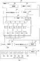
- FIG. 1 is a block diagram for explaining the outline of this embodiment.
- a business system that executes a predetermined business and a management server 100 that manages the business system are connected via a management network.
- the business system is connected to an external network via a business network.
- the business system shown in FIG. 1 includes one database server 10, two application servers 11, four Web servers 12, and one load balancer 13.
- the configuration of a database server or the like constituting the business system is also referred to as a business node.
- the business system is built on a computer system that provides computer resources.
- the computer system includes a physical layer composed of a physical computer and a physical switch, and a logical layer composed of a virtual computer realized using the physical computer and a virtual switch realized using the physical switch.
- a physical computer configuring a physical layer is described as a physical node
- a virtual computer configuring a logical layer is also described as a logical node.
- Business nodes are realized using physical nodes and logical nodes.
- the database server may be realized using the blade server 223 which is a physical node, or the database server is generated using a virtual machine generated on the blade server 223, that is, a logical node. May be realized.
- This example aims to estimate the performance limit of the business system.
- a business node having strict performance requirements in the business system is identified according to the following procedure, and a load test is performed on the identified business node.
- the management server 100 first identifies an important business node in the business system based on the configuration of the business system and the configuration of the computer system on which the business system is constructed.
- important business nodes are also referred to as important nodes.
- the management server 100 performs a load test on the important node and measures the influence of the entire business system.
- the management server 100 calculates a minimum cut set (influence range) that is a combination of nodes having a large influence on the business system, based on the measurement result of the load test described above.
- the minimum cut set includes one or more important nodes. Further, the management server 100 estimates the magnitude of the influence on the business node included in the influence range due to the change in the load of the important node.
- the performance limit (performance characteristics) of the business system can be estimated.
- the measurement result of the load test when the allocated resource amount of the database server identified as the important node is reduced by 30% is shown.
- a minimum cut set as indicated by a dotted line is calculated. That is, in the business system, it is possible to identify a business node that is affected by the load of the database server that is an important node.
- the management server 100 executes a monitoring process based on the load test measurement result during operation of the business system. At this time, the management server 100 displays a meter 15 indicating an estimated value or a dangerous value of the load of the business node included in the influence range. This makes it possible to estimate whether the computer system and the business system need to be expanded.
- FIG. 2 is an explanatory diagram illustrating an example of a configuration of the entire system according to the first embodiment.
- the system in the first embodiment includes a management server 100 and a computer system on which a business system is constructed.
- the computer system is a system that provides computer resources, and includes a plurality of server apparatuses 220, a storage subsystem 260, an NW-SW 250, and an FC-SW 140.
- Management server 100 manages the computer system.
- the management server 100 is connected to the management interface (management I / F) 211 of the NW-SW 210 and the management interface 251 of the NW-SW (business network switch) 250 via the NW-SW (management network switch) 210.
- the management server 100 can set a VLAN (Virtual LAN) for each NW-SW 210, 250.
- VLAN Virtual LAN
- the NW-SW 210 constitutes a management network.
- the management network is a network for managing the operation of the management server 100 such as OS and application distribution, power control, etc. operating on the plurality of server apparatuses 220.
- NW-SW 250 constitutes a business network.
- the business network is a network used by an application executed by the server device 220 or a virtual machine (VM) on the server device 220.
- the NW-SW 250 communicates with an external client computer connected via a WAN or the like.
- physical computer resources such as the server device 220, the FC-SW 140, the NW-SW 250, and the storage subsystem 260 are called physical nodes, and virtual computer resources such as VMs and virtual switches are called logical nodes. .
- the management server 100 is connected to the management interface (management I / F) 161 of the storage subsystem 260 via the FC-SW (Fibre Channel switch) 140.
- the management server 100 manages an LU (Logical Unit) 162 in the storage subsystem 260.
- the management server 100 manages N LU1 to LUn.
- the management server 100 includes a control unit 201 and holds a management table group 202.
- the management table group 202 includes computer system configuration information and the like.
- the control unit 201 refers to the information included in the management table group 202, executes a load test (black box test) on the business system constructed on the computer system, and based on the measurement result of the load test.
- the information included in the management table group 202 is updated. Details of the configuration of the management server 100 will be described later with reference to FIG.
- the server apparatus 220 provides computer resources to be allocated to business nodes as will be described later.
- the server device 220 is connected to the NW-SWs 210 and 250 via I / O devices or the like.
- the server device 220 includes a service processor 221 and a plurality of blade servers 223.
- the service processor 221 monitors the blade server 223 mounted on the server device 220.
- the server device 220 is connected to the management server 100 via the service processor 221.
- the blade server 223 runs an OS and applications. The software configuration and hardware configuration of the blade server 223 will be described later with reference to FIG.
- one or more VMs can be generated in the blade server 223.
- one or more virtual switches can be generated in the FC-SW and NW-SW 250.
- a virtual switch may be generated on the blade server 223.
- the server device 220 includes the blade server 223, but the present embodiment is not limited to this.
- a general computer including a processor, a memory, a network interface, and the like may be used as the server device 220.
- the storage subsystem 260 provides a storage area used by an OS or the like operating on the server device 220.
- the storage subsystem 260 includes a controller (not shown), a plurality of storage media (not shown), a disk interface (not shown), and a network interface (not shown).
- a storage medium an HDD (Hard Disk Drive), an SSD (Solid State Drive), or the like can be considered.
- the controller (not shown) configures a RAID using a plurality of storage media (not shown), and generates a plurality of LUs 162 from the RAID volume.
- the storage subsystem 260 provides the LU 162 as a storage area used by the OS or the like.
- FIG. 3 is a block diagram illustrating a configuration example of the management server 100 according to the first embodiment.
- the management server 100 includes a processor 301, a memory 302, a disk interface 303, and a network interface 304.
- the processor 301 executes a program stored in the memory 302.
- the memory 302 stores a program executed by the processor 301 and information necessary for executing the program.
- the program and information stored in the memory 302 will be described later.
- the disk interface 303 is an interface for accessing the storage subsystem 260.
- the network interface 304 is an interface for communicating with other devices via the IP network.
- the management server 100 may include a BMC (Basement Management Controller) that performs power control and control of each interface.
- BMC Base Management Controller
- the memory 302 stores a program for realizing the control unit 201 and a management table group 202.
- the control unit 201 includes a plurality of program modules. Specifically, the control unit 201 includes a weight calculation unit 310, a measurement unit 311, an estimation unit 312, and a business system monitoring unit 313.
- the processor 301 operates as a functional unit that realizes a predetermined function by operating according to a program module that implements the weight calculation unit 310, the measurement unit 311, the estimation unit 312, and the business system monitoring unit 313.
- the processor 301 functions as the weight calculation unit 310 by operating according to a program module that implements the weight calculation unit 310. The same applies to other programs.
- the weight calculation unit 310 calculates a weight for evaluating the importance of each of a plurality of business nodes in the business system.
- the weight calculation unit 310 according to the first embodiment calculates the weight of the business node based on the configuration of the physical computer resource (physical node) and the configuration of the logical computer resource (logical node). Details of the processing executed by the weight calculation unit 310 will be described later with reference to FIG.
- the measuring unit 311 measures the influence on the business system by executing a predetermined load test (black box test) on the business node. Details of processing executed by the measurement unit 311 will be described later with reference to FIG.
- the estimation unit 312 generates information for estimating the performance limit of the business system based on the measurement result. Details of the processing executed by the estimation unit 312 will be described later with reference to FIG.
- the business system monitoring unit 313 monitors the business system based on the information related to the performance limit of the business system and displays the monitoring result. Further, the business system monitoring unit 313 may display the processing results of the weight calculation unit 310, the measurement unit 311, and the estimation unit 312. Details of processing executed by the business system monitoring unit 313 will be described later with reference to FIG.
- the management table group 202 stores various information for managing the computer system and the business system. Specifically, the management table group 202 includes a topology management table 320, a logical configuration management table 321, a business management table 322, a node management table 323, a threshold management table 324, an adjustment method management table 325, a system performance table 326, and a weight management. A table 327 and a rule management table 328 are included.
- the topology management table 320 stores information on physical nodes. Details of the topology management table 320 will be described later with reference to FIG.
- the logical configuration management table 321 stores information on logical nodes. Details of the logical configuration management table 321 will be described later with reference to FIG.
- the business management table 322 stores information related to programs executed in the business system. Details of the business management table 322 will be described later with reference to FIG.
- the node management table 323 stores information on business nodes. Details of the node management table 323 will be described later with reference to FIG.
- the threshold management table 324 stores thresholds for selecting important nodes based on the weights of business nodes. Details of the threshold management table 324 will be described later with reference to FIG.
- the adjustment method management table 325 stores a load test policy. Details of the adjustment method management table 325 will be described later with reference to FIG.
- the system performance table 326 stores the measurement result of the load test. Details of the system performance table 326 will be described later with reference to FIG.
- the weight management table 327 stores information on the importance of business nodes and the relationship between business nodes in the business system. Details of the weight management table 327 will be described later with reference to FIG.
- the rule management table 328 stores a method for changing the configuration of the business system or the computer system and the details of the change. Details of the rule management table 328 will be described later with reference to FIG.
- Each table in the program and management table group 202 that realizes the control unit 201 includes a storage subsystem 260, a nonvolatile semiconductor memory, a hard disk drive, a storage device such as an SSD (Solid State Drive), or an IC card, an SD card, or a DVD. Etc., and can be stored in a non-transitory data storage medium readable by a computer.
- a storage subsystem 260 a nonvolatile semiconductor memory
- a hard disk drive such as an SSD (Solid State Drive), or an IC card, an SD card, or a DVD. Etc., and can be stored in a non-transitory data storage medium readable by a computer.
- the server type of the management server 100 may be any of a physical server, a blade server, a virtualized server, a logically partitioned server, a physically partitioned server, and the like. The effects of the embodiment can be obtained.
- FIG. 4 is a block diagram illustrating a configuration example of the blade server 223 according to the first embodiment.
- the blade server 223 includes a processor 401, a memory 402, a network interface 403, a disk interface 404, a BMC 405, and a PCI-Express interface 406.
- the processor 401 executes a program stored in the memory 402.
- the memory 402 stores a program executed by the processor 401 and information necessary for executing the program.
- the program and information stored in the memory 302 will be described later.
- the network interface 403 is an interface for communicating with other devices via the IP network.
- the disk interface 404 is an interface for accessing the storage subsystem 260.
- the BMC 405 performs power supply control and control of each interface.
- the PCI-Express interface 406 is an interface for connecting to the PCIex-SW.
- the memory 402 stores a program for realizing the OS 411, the application 421, and the monitoring unit 422.
- the processor 401 manages devices in the blade server 223 by executing the OS 411 on the memory 402. Under the OS 411, an application 421 that provides a business and a monitoring unit 422 operate.
- the memory 402 may store a program that realizes a virtualization unit that manages a virtual machine, as will be described later.
- one network interface 403, one disk interface 404, and one PCI-Express interface 406 are shown, but a plurality of interfaces may be provided.
- the blade server 223 may have a network interface connected to the NW-SW 210 and a network interface connected to the NW-SW 250.
- FIG. 5 is an explanatory diagram illustrating an example of the topology management table 320 according to the first embodiment.
- the topology management table 320 stores information related to the physical configuration of the computer system in which the business system is constructed. Specifically, the topology management table 320 includes an identifier 501, UUID 502, physical node identifier 503, device name 504, property 505, connection destination device name 506, reliability type 507, and unique value 508.
- the identifier 501 is an identifier for uniquely identifying an entry in the topology management table 320.
- the UUID 502 stores a UUID (Universal Unique IDentifier) that is an identifier whose format is defined so as not to overlap.
- the physical node identifier 503 is an identifier for uniquely identifying a physical node constituting the physical layer. In this embodiment, the device identifier is used as the physical node identifier.
- the device name 504 is an identifier for uniquely identifying a device included in the physical node. In the case of an entry representing the physical node itself, the device name 504 is blank.
- Property 505 is information indicating the performance of the physical node itself or the performance of the device corresponding to the device name 504.
- the property 505 stores information such as the vendor type, RAID configuration, virtualization type, support function, and firmware version.
- the connection destination device name 506 stores information on other devices connected to the device corresponding to the device name 504.
- the connection destination device name 506 stores an identifier of another physical node connected to the physical node.
- the reliability type 507 is information related to a configuration such as redundancy of a device corresponding to the physical node or the connection destination device name 506.
- the unique value 508 is a value for evaluating the importance of the physical node or device corresponding to the entry. That is, the eigenvalue 508 is a value for evaluating the importance of the configuration of the physical layer in the computer system.
- the configuration of the physical layer includes a hardware configuration, a software configuration, a connection configuration between a plurality of physical nodes, and the like.
- the eigenvalue 508 may be set in advance, or may be set by an administrator who operates the management server 100 or the like.
- FIG. 6 is an explanatory diagram illustrating an example of the logical configuration management table 321 according to the first embodiment.
- the logical configuration management table 321 stores information related to node characteristics in the business system. Specifically, the logical configuration management table 321 includes an identifier 601, a UUID 602, a logical node identifier 603, a type 604, an adjustment metric 605, an adjustment parameter 606, a physical node identifier 607, a system configuration 608, a column connection 609, and a unique value 610. Including.
- the identifier 601 is an identifier for uniquely identifying an entry in the logical configuration management table 321.
- the logical node identifier 603 is an identifier for uniquely identifying a logical node constituting the logical layer. In this embodiment, the identifiers of the VM and the virtual switch are used as logical node identifiers.
- the type 604 is information indicating the type of performance change method that can be supported by the logical node.
- the adjustment metric 605 is an item measured for grasping the load of the logical node in the black box test. For example, since “CPU”, “I / O”, and “memory” are stored in the adjustment metric 605 of the entry with the identifier 601 “1”, the processor usage rate, the number of I / Os, or the memory usage in the logical node 1 The rate is the measurement target.
- the adjustment parameter 606 is a parameter to be adjusted when the load on the logical node is changed in the black box test.
- the physical node identifier 607 is an identifier of a physical node that allocates computer resources to the logical node.
- the physical node identifier 607 is the same as the physical node identifier 503.
- the system configuration 608 is information regarding the configuration of logical nodes in the logical layer.
- the system configuration 608 stores “scale-out type”, “scale-up type”, and “mesh type” as information indicating the system configuration.
- “scale-out type” indicates a configuration in which logical nodes of the same type perform processing in parallel.
- a unique value for the configuration of the logical node in the logical layer is set. For example, “1.0” is set as the unique value in the system configuration 608 of the entry whose identifier 601 is “1”.
- the system configuration 608 stores an identifier of a logical node that constructs a cluster or an identifier of a logical node connected in parallel.
- the column connection 609 is an identifier of a logical node connected to the logical node corresponding to the logical node identifier 603 by a serial configuration.
- a Web three-layer model may be considered as the serial configuration.
- the unique value 610 is a value for evaluating the importance of the logical node corresponding to the logical node identifier 603. That is, the eigenvalue 610 is a value for evaluating the importance of the configuration of the logical layer in the computer system.
- the configuration of the logical layer includes a hardware configuration, a software configuration, a connection configuration between a plurality of logical nodes, and the like.
- the eigenvalue 610 may be set in advance, or may be set by an administrator who operates the management server 100.
- FIG. 7 is an explanatory diagram illustrating an example of the business management table 322 according to the first embodiment.
- the business management table 322 stores information related to business executed in the business system. Specifically, the business management table 322 includes a business identifier 701, UUID 702, business software name 703, business setting information 704, priority order 705, and unique value 706.
- the business identifier 701 is an identifier for uniquely identifying a business in the business system.
- the business software name 703 is a name of software executed to provide a business.
- the task setting information 704 is setting information necessary for executing a task corresponding to the task identifier 701.
- the priority order 705 is a business priority order in the business system. A smaller value of the priority 705 indicates a more important work.
- the priority order 705 also stores information related to the configuration necessary for business.
- the eigenvalue 706 is a value for evaluating the importance of the work.
- FIG. 8 is an explanatory diagram illustrating an example of the node management table 323 according to the first embodiment.
- the node management table 323 stores information related to business nodes constituting the business system. Specifically, the node management table 323 includes a business node identifier 801, a UUID 802, an assigned node identifier 803, a business type 804, a business identifier 805, a connection node identifier 806, and related information 807.
- the business node identifier 801 is an identifier for uniquely identifying a business node in the business system.
- the assigned node identifier 803 is an identifier of a node that provides computer resources to the business node.
- the physical node identifier is stored in the allocation node identifier 803, and when a logical node provides a computer resource to the business node, the logical node identifier is stored in the allocation node identifier 803. Is stored.
- the business type 804 is a business type executed by the business node.
- the business identifier 805 is a business identifier corresponding to the business type 804.
- the business identifier 805 is the same as the business identifier 701.
- the connection node identifier 806 is an identifier of another business node connected to the business node corresponding to the business node identifier 801.
- the related information 807 is information related to the configuration necessary for the business node.
- no eigenvalue is set for the business node. This is because even if the business system is the same, if the configuration of the computer system in which the business system is constructed and the content of the business executed in the business system are different, the relationship between business nodes and the performance limit of the business node This is because they are different.
- the management server 100 calculates a weight indicating the importance of the business node based on the configuration of the physical layer, the configuration of the logical layer, and the content of the business.
- the management server 100 identifies an important node of the business system based on the calculated business node weight.
- Important nodes are highly likely to have a significant impact on business systems. Therefore, efficient measurement can be performed by executing a load test for important nodes. Further, by grasping the behavior of the entire business system with respect to the load on the important node, the performance limit of the business system can be estimated.
- the load test may be performed on a business node other than the important node. For example, a method of performing a load test on a business node connected to an important node can be considered.
- This embodiment improves the calculation efficiency and increases the accuracy of the load test by executing the load test only on important nodes.
- node management table 323 for one business system.
- the node management table 323 is associated with a business system identifier.
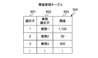
- FIG. 9 is an explanatory diagram illustrating an example of the threshold management table 324 according to the first embodiment.
- the threshold management table 324 stores thresholds used when the management server 100 identifies important nodes. Specifically, the threshold management table 324 includes an identifier 901, a business identifier 902, and a threshold 903.
- the identifier 901 is an identifier for uniquely identifying an entry in the threshold management table 324.
- the business identifier 902 is an identifier for uniquely identifying a business in the business system.
- the business identifier 902 is the same as the business identifier 701.
- the threshold value 903 is a threshold value in business.
- a threshold is set for each business, but one threshold may be set for the business system.
- FIG. 10 is an explanatory diagram illustrating an example of the adjustment method management table 325 according to the first embodiment.
- the adjustment method management table 325 stores information on a load adjustment method for a physical node or a logical node in a load test. Specifically, the adjustment method management table 325 includes an identifier 1001, a node type 1002, and an adjustment method 1003.
- the identifier 1001 is an identifier for uniquely identifying an entry in the adjustment method management table 325.
- the node type 1002 is the type of node to be adjusted.
- the node type 1002 stores “physical server”, “SW”, “VM”, “vSW”, and the like.
- the adjustment method 1003 includes information on a load adjustment method for a physical node or a logical node corresponding to the node type 1002. Specifically, the adjustment method 1003 includes an adjustment parameter type 1004, an adjustment value 1005, and a priority 1006.
- the adjustment parameter type 1004 is a type of a parameter (adjustment parameter) to be adjusted in a node corresponding to the node type 1002.
- the adjustment value 1005 is an adjustment value of the adjustment parameter.
- the priority 1006 is a priority order of the adjustment method. More specifically, a value for determining an adjustment method to be applied when there are a plurality of entries having the same node type 1002 and adjustment parameter type 1004 and different adjustment values 1005 is stored. In this embodiment, it is assumed that the smaller the value is, the higher the priority is.
- the node type 1002 of the entry whose identifier 1001 is “1” is “VM”, the adjustment parameter type 1004 is “CPU”, and the adjustment value 1005 is “ ⁇ 10%”.
- the management server 100 decreases the allocation rate of the virtual processors allocated to the VM by “ ⁇ 10%”, and measures the influence of the entire business system.
- the management server 100 measures the influence of the entire business system by decreasing the virtual processor allocation rate by “ ⁇ 10%”.
- the node type 1002 of the entry whose identifier 1001 is “5” is “VM”, the adjustment parameter type 1004 is “VM”, and the adjustment value 1005 is “ ⁇ 1”.
- the management server 100 decreases the number of VMs by “ ⁇ 1” and measures the influence of the entire business system.
- the management server 100 decreases the number of VMs by “ ⁇ 1” and measures the influence of the entire business system.
- the management server 100 decreases the number of virtual processors for the VM by “ ⁇ 1” and restarts, and then measures the influence of the entire business system.
- the management server 100 decreases the number of virtual processors by “ ⁇ 1” and restarts, and then measures the influence of the entire business system.
- FIG. 11 is an explanatory diagram illustrating an example of the system performance table 326 according to the first embodiment.
- the system performance table 326 stores information on the performance characteristic function generated based on the measurement result of the load test. Specifically, the system performance table 326 includes an identifier 1101, an important node identifier 1102, a related node identifier 1103, and a performance characteristic function 1104.
- the identifier 1101 is an identifier for uniquely identifying an entry in the system performance table 326.
- the system performance table 326 has one entry for one important node.
- the important node identifier 1102 is an identifier of a business node that is an important node.
- the related node identifier 1103 is an identifier of the business node affected by the important node.
- One or more related nodes exist for one important node.
- a business node affected by an important node is also referred to as a related node.
- the performance characteristic function 1104 stores information on the performance characteristic function indicating the relationship between the important node and the related node. Specifically, the performance characteristic function 1104 includes an adjustment parameter type 1105 and a function 1106.
- the adjustment parameter type 1105 is an adjustment parameter in the important node, and corresponds to a variable of the performance characteristic function.
- the function 1106 stores a performance characteristic function.
- the performance characteristic function is calculated as a change in the load of the related node with respect to the adjustment parameter. Assume that the load on the related node is the processor usage rate. Note that a memory usage rate, a network usage rate, a response time, and the like may be used as the load on the related node.
- X stored in the function 1106 is the value of the adjustment parameter corresponding to the adjustment parameter type 1105
- Y represents the load of the related node
- system performance table 326 for one business system.
- the system performance table 326 is associated with a business system identifier.
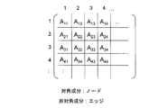
- FIG. 12 is an explanatory diagram illustrating an example of the weight management table 327 according to the first embodiment.
- FIG. 13 is an explanatory diagram illustrating a notation example in a matrix format of the weight management table 327 according to the first embodiment.
- the weight management table 327 stores information on the strength of relevance between business nodes calculated from the load test measurement results. Specifically, the weight management table 327 includes an identifier 1201, a type 1202, a parameter type 1203, a business node identifier 1204, and a weight 1205.
- the identifier 1201 is an identifier for uniquely identifying an entry in the weight management table 327.
- the type 1202 is a target type for which a weight is calculated. In the case of an entry corresponding to a node weight, “node” is stored in the type 1202, and in the case of an entry corresponding to the edge weight connecting two nodes, “edge” is stored in the type 1202.
- the parameter type 1203 stores the type of parameter that one business node affects the other business node.
- the business node identifier 1204 is an identifier of a business node related to the type 1202. For example, when the type 1202 is “node”, the business node identifier 1204 stores the identifier of one business node, and when the type 1202 is “edge”, the identifiers of two business nodes connected by the edge are stored. Is done.
- the weight 1205 is a business node weight or an edge weight.
- the business node weight is a value for evaluating the importance of the business node in the business system.
- the edge weight is a value for evaluating the strength of the relationship between the business nodes.
- the weight management table 327 shown in FIG. 12 can be expressed as data in a matrix format as shown in FIG.
- the diagonal component of the matrix corresponds to the node weight
- the non-diagonal component of the matrix corresponds to the edge weight.
- the matrix component A11 corresponds to the weight of the business node 1
- the matrix component A12 corresponds to the weight of the edge connecting the business node 1 and the business node 2.
- weight management table 327 for one business system.
- the business management system identifier is associated with the weight management table 327.
- FIG. 14 is an explanatory diagram illustrating an example of the rule management table 328 according to the first embodiment.
- the rule management table 328 stores a method for changing the configuration of the business system or the computer system and the details of the change. Specifically, the rule management table 328 includes a business identifier 1401, a UUID 1402, a business type 1403, related information 1404, a priority order 1405, and a rule 1406.
- the business identifier 1401 is an identifier for uniquely identifying a business in the business system.
- the business identifier 1401 is the same as the business identifier 701.
- the business type 1403 is a business type executed by the business node.
- the business type 1403 is the same as the business type 804.
- the related information 1404 is information related to the configuration necessary for the business corresponding to the business type.
- the priority order 1405 is a priority order of business in the business system. In the present embodiment, it is assumed that the priority is higher as the value of the priority 1405 is smaller.
- the rule 1406 is a change in the specific configuration of the business system. In this embodiment, the rule 1406 stores one or more changes. In this case, all the changes may be applied, or the changes may be applied until it is confirmed that the performance of the business system has been improved.
- FIG. 15 is a flowchart illustrating an outline of processing executed by the management server 100 according to the first embodiment.
- the control unit 201 of the management server 100 starts processing upon receiving a load test execution instruction from a user or the like.
- the opportunity for the management server 100 to start processing is not limited to this.
- the management server 100 may execute the process periodically, or may start the process when a change in the business system or the computer system is detected.
- the management server 100 receives the identifier of the business system to be processed.
- the control unit 201 first executes a node selection process (step S100).
- the control unit 201 analyzes the configuration of the computer system and selects one or more important nodes from a plurality of business nodes that configure the business system based on the analysis result. Details of the node selection processing will be described later with reference to FIG.
- the control unit 201 executes measurement processing (step S101), and executes aggregation processing based on the result of the measurement processing (step S102).
- step S101 a load test focusing on the important node selected in the node selection process is executed.
- step S102 a load test focusing on the important node selected in the node selection process is executed.
- step S102 information indicating the relationship between the two business nodes is generated based on the result of the measurement process. Details of the measurement process will be described later with reference to FIG. Details of the tabulation process will be described later with reference to FIG.
- step S100 to step S102 is processing executed before the operation of the business system.
- the control unit 201 executes a monitoring process for the business system based on the results of the measurement process and the aggregation process (step S103). Details of the monitoring process will be described later with reference to FIG.
- FIG. 16 is a flowchart illustrating an example of node selection processing according to the first embodiment.
- the weight calculation unit 310 included in the control unit 201 executes node selection processing.
- the weight calculation unit 310 starts a loop process for the business node (step S200). At this time, the weight calculation unit 310 selects a business node to be processed from business nodes included in the business system.
- the weight calculation unit 310 refers to the node management table 323 corresponding to the input business system identifier and selects one entry. In this embodiment, it is assumed that the weight calculation unit 310 sequentially selects entries from the node management table 323. Note that a priority order may be set in advance according to the business type or business content, and the weight calculation unit 310 may select an entry based on the priority order.
- the weight calculation unit 310 acquires eigenvalues related to the selected business node from the topology management table 320 and the logical configuration management table 321 (step S201). Specifically, the following processing is executed.
- the weight calculation unit 310 refers to the assigned node identifier 803 of the entry selected from the node management table 323 and identifies a node that provides computer resources to the selected business node.
- the weight calculation unit 310 refers to the topology management table 320 and searches for all entries in which the physical node identifier 503 matches the assigned node identifier 803. The weight calculation unit 310 acquires all the values of the eigenvalues 508 of the searched entries.
- the weight calculation unit 310 refers to the logical configuration management table 321 and searches for an entry in which the logical node identifier 603 matches the assigned node identifier 803. The weight calculation unit 310 acquires the value included in the system configuration 608 of the retrieved entry and the value of the eigenvalue 610.
- the weight calculation unit 310 refers to the topology management table 320 and searches for all entries in which the physical node identifier 503 matches the physical node identifier 607 of the entry retrieved from the logical configuration management table 321. The weight calculation unit 310 acquires all the unique values 508 of the searched entries.
- physical nodes such as the blade server 223 are treated as business nodes, and physical nodes such as the NW-SW 250 are not treated as business nodes.
- a physical node such as NW-SW 250 is treated as an edge. Therefore, when the weight calculation unit 310 calculates the eigenvalue, it is necessary to set in advance whether it is necessary to consider a physical node such as the NW-SW 250.
- it is assumed that a physical node to be considered when calculating the eigenvalue is set in advance for the business node.
- the eigenvalue of the physical node included in the edge may be used as the edge weighting coefficient.
- step S201 The above is the description of the processing in step S201.
- the weight calculation unit 310 calculates the weight of the business node by using the eigenvalue acquired from the topology management table 320 and the logical configuration management table 321 (step S202).
- the weight calculation unit 310 calculates the weight of the business node by using the eigenvalue acquired from the topology management table 320 and the logical configuration management table 321 (step S202).
- the following calculation method can be considered.
- the weight calculation unit 310 calculates the first total value by adding all the values acquired from the eigenvalue 508 of the topology management table 320. .
- the first total value becomes the weight of the business node.
- the weight calculation unit 310 calculates the first total value by adding all the values acquired from the eigenvalue 508 of the topology management table 320. . Further, the weight calculation unit 310 calculates the second total value by adding the value included in the system configuration 608 of the logical configuration management table 321 and the value of the eigenvalue 610. Furthermore, the weight calculation unit 310 calculates the third total value by adding the first total value and the second total value. The third total value becomes the weight of the business node.
- the weight calculation unit 310 calculates the weight of the business node by multiplying the first total value by the second total value.
- the business node weight calculation method described above is merely an example, and the present embodiment is not limited to the business node weight calculation method. Any method may be used as long as it can calculate an index (weight) for evaluating the importance of the business node from the configuration of the physical layer and the configuration of the logical layer.
- the weight calculation unit 310 updates the weight management table 327 based on the calculated weight (step S203).
- the weight calculation unit 310 adds an entry to the weight management table 327 and sets a predetermined identifier as the identifier 1201 of the added entry.
- the weight calculation unit 310 sets “node” as the type 1202 of the added entry, sets the identifier of the business node to be processed as the business node identifier 1204, and sets the calculated weight as the weight 1205.
- the parameter type 1203 remains blank.
- the weight calculation unit 310 determines whether or not the business node weight is greater than the threshold (step S204).
- the weight calculation unit 310 refers to the threshold management table 324 and searches for an entry in which the business identifier 902 matches the business identifier 805 of the entry selected from the node management table 323. The weight calculation unit 310 determines whether the business node weight is greater than the threshold value 903 of the searched entry.
- the weight calculation unit 310 proceeds to step S206.
- the weight calculation unit 310 registers the selected business node in the verification list (step S205).
- the verification list is a list in which important nodes are registered.
- the weight calculation unit 310 registers the entry of the selected business node in the verification list. In this embodiment, the weight calculation unit 310 registers an entry having the same content as the entry corresponding to the business node in the logical configuration management table 321 in the verification list. Furthermore, the weight calculation unit 310 sorts the entries stored in the verification list based on the business node weights. In the present embodiment, the weight calculation unit 310 rearranges the entries in descending order of the business node weight.
- the weight calculation unit 310 If the verification list does not exist, the weight calculation unit 310 generates a verification list in the work area of the memory 302, and registers a business node entry in the generated verification list.
- the weight calculation unit 310 determines whether or not the processing has been completed for all business nodes of the business system to be processed (step S206). If it is determined that the processing has not been completed for all the business nodes of the business system to be processed, the weight calculation unit 310 returns to step S200 and executes the same processing for the new business node.
- the weight calculation unit 310 ends the processing.
- FIG. 17 is a flowchart illustrating an example of the measurement process according to the first embodiment.
- a measurement unit 311 included in the control unit 201 executes measurement processing.
- the measurement unit 311 starts loop processing of important nodes (step S300). At this time, the measurement unit 311 selects one important node entry from the verification list. Since the entries in the verification list of this embodiment are arranged in descending order of weight, the measurement unit 311 selects the entries in the order from the top of the verification list. In addition, the measurement unit 311 adds an entry to the system performance table 326, sets a predetermined identifier in the identifier 1101, and sets the identifier of the selected important node in the important node identifier 1102.
- the measurement unit 311 refers to the adjustment method management table 325 and specifies a verification method to be applied to the selected important node (step S301). Specifically, the following processing is executed.
- the measuring unit 311 acquires an identifier from the assigned node identifier 803 of the selected important node entry.
- the measuring unit 311 identifies the device from the identifier of the physical node.
- the measurement unit 311 acquires all entries whose node type 1002 is “physical server” from the adjustment method management table 325. If the device is a switch, the measurement unit 311 acquires all entries whose node type 1002 is “SW” from the adjustment method management table 325.
- the measuring unit 311 identifies a logical device from the logical node identifier.
- the measurement unit 311 acquires all entries whose node type 1002 is “VM” from the adjustment method management table 325.
- the measurement unit 311 acquires all entries whose node type 1002 is “vSW” from the adjustment method management table 325.
- the measurement unit 311 refers to the topology management table 320, identifies the physical node to which the logical node is associated, and uses the same method as that described in (1) from the adjustment method management table 325, Get all entries corresponding to the physical node.
- the measurement unit 311 starts a loop process of the verification method (from step S302 to step S309).
- the measuring unit 311 adjusts at least one parameter of the physical node or the logical node for each specified verification method, and measures the load on the entire business system.
- the measurement unit 311 selects one specified verification method, and starts measurement processing based on the selected verification method (step S302). At this time, when there are a plurality of entries having the same adjustment parameter type 1004 and adjustment value 1005, the measurement unit 311 selects an entry based on the value of the priority 1006.
- the measurement unit 311 changes parameters of the physical node or logical node according to the selected verification method (step S303), and measures various loads in the business system (step S304).
- the load of each business node in the business system is measured.
- the measurement unit 311 measures the processor usage rate, memory usage rate, network bandwidth usage rate, throughput, and the like of the business node as loads.
- the number of requests processed (throughput) in the business node is measured as a load.
- the measurement unit 311 stores the measurement result 1800 in the work area of the memory 302 or the storage area of the storage subsystem 260.
- the measurement result 1800 will be described with reference to FIG.
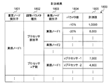
- FIG. 18 is an explanatory diagram showing an example of the measurement result 1800 of the first embodiment.
- the measurement result 1800 shown in FIG. 18 there is one entry for one entry in the verification list. That is, the measurement result 1800 includes the same number of entries as the important node.
- the entry includes an important node identifier 1801, an adjustment parameter type 1802, a business node identifier 1803, a parameter value 1804, and a measured value 1805.
- the important node identifier 1801 is an identifier of the important node selected in step S300.
- the important node identifier 1801 stores the same identifier as the identifier stored in the business node identifier 801.
- the adjustment parameter type 1802 is the type of the adjustment parameter adjusted in step S303.
- the adjustment parameter type 1802 is the same as the adjustment parameter type 1004.
- the business node identifier 1803 is an identifier of the business node whose load is measured.
- the business node identifier 1803 is the same as the business node identifier 801.
- the parameter value 1804 is a parameter value actually adjusted by the measurement unit 311 according to the verification method selected in step S302.
- the measured value 1805 is a value indicating the load of the business node corresponding to the business node identifier 1803 when the parameter is adjusted to the value indicated by the parameter value 1804.
- the measuring unit 311 determines whether or not processing has been completed for all specified verification methods (step S305). When it is determined that the processing has not been completed for all the specified verification methods, the measurement unit 311 returns to step S302 and executes the same processing for the new verification method.
- the measurement unit 311 When it is determined that the processing has been completed for all the specified verification methods, the measurement unit 311 has completed the processing for all the important nodes, that is, whether the processing has been completed for all the entries included in the verification list. It is determined whether or not (step S306). If it is determined that the processing has not been completed for all the important nodes, the measurement unit 311 returns to step S300 and executes the same processing for the new important node.
- the measurement unit 311 updates the system performance table 326 based on the measurement result 1800 (step S307), and then ends the processing. Specifically, the following processing is executed.
- the measurement unit 311 reads one entry from the measurement result 1800, and adds one entry to the system performance table 326.
- the measurement unit 311 sets a predetermined identifier in the identifier 1101 of the added entry, and sets an identifier stored in the important node identifier 1801 in the important node identifier 1102.
- the measuring unit 311 selects one adjustment parameter type 1802 and identifies a business node whose load has changed by a certain value or more. For example, the measurement unit 311 calculates the load fluctuation rate by analyzing the measurement value 1805 corresponding to the business node identifier 1803, and determines whether or not the calculated load fluctuation rate is 20% or more. A business node having a calculated load fluctuation rate of 20% or more is identified as a business node whose load has changed by a certain value or more.
- the measuring unit 311 may select the business node.
- the measurement unit 311 sets the business node identifier specified by the above-described processing in the business node identifier 1803 of the entry added to the system performance table 326. In addition, the measurement unit 311 sets information stored in the adjustment parameter type 1802 selected in the above-described processing in the adjustment parameter type 1105 of the entry.
- the measuring unit 311 calculates a performance characteristic function based on the analysis result of the processing described above.
- the measurement unit 311 calculates the performance characteristic function with the value of the adjustment parameter corresponding to the adjustment parameter type 1105 as the domain (X) and the throughput as the range (Y).
- the measurement unit 311 sets the calculated function as the function 1106. Thereafter, the system performance table 326 is updated according to the same procedure.
- FIG. 19 is a flowchart for explaining an example of the counting process according to the first embodiment.
- the estimation unit 312 included in the control unit 201 executes the aggregation process.
- the estimation unit 312 first starts loop processing of important nodes (step S400). At this time, the estimation unit 312 selects one entry from the system performance table 326. In the following description, the selected entry is also described as an important node entry.
- the estimation unit 312 starts the adjustment parameter loop processing (step S401). Specifically, the estimation unit 312 extracts all types of adjustment parameters from the adjustment parameter type 1105 of the important node entry, and selects one adjustment parameter to be processed from the extracted adjustment parameters.
- the estimation unit 312 starts a loop process for business nodes (step S402). Specifically, the following processing is executed.
- the estimation unit 312 extracts the identification of the related node from the business node identifier 1803 of the line including the selected adjustment parameter in the adjustment parameter type 1105 of the important node entry.
- the estimation unit 312 selects one identifier of the related node from the extracted identifiers of the business nodes.
- the estimation unit 312 refers to the node management table 323 and identifies another business node connected to the selected business node.
- the estimation unit 312 calculates the number of business nodes that pass from the important node to the selected business node as the first hop count.
- the estimation unit 312 calculates the number of business nodes that pass from the important node to the identified business node as the second hop count.
- the estimation unit 312 determines whether or not the first hop number is larger than the second hop number. If the first hop count is less than or equal to the second hop count, the estimating unit 312 proceeds to step S403. When the first hop number is larger than the second hop number, the estimation unit 312 proceeds to step S405. The above is the description of the process in step S402.
- the estimation unit 312 calculates the weight of the edge connecting the two business nodes (step S403).
- the edge weight There are various methods for calculating the edge weight. For example, the following methods can be considered.
- the estimation unit 312 acquires the performance characteristic function from the function 1106 in the row that matches the important node, the related node, and the adjustment parameter selected in Step S400 to Step S402.
- the estimation unit 312 calculates the maximum value of the differential coefficient in the performance characteristic function based on the performance characteristic function and the domain of the variable X as the edge weight.
- the estimation unit 312 refers to the measurement result 1800 and acquires a necessary value from the measurement value 1805 that matches the identifier of the important node, the related node, and the adjustment parameter. The above is the description of the process in step S403.
- the estimation unit 312 updates the weight management table 327 based on the calculated edge weight (step S404).
- the estimation unit 312 adds an entry to the weight management table 327 and sets a predetermined identifier in the identifier 1201 of the added entry.
- the estimation unit 312 sets “edge” in the type 1202 of the added entry, and sets the selected adjustment parameter in the parameter type 1203. Further, the estimation unit 312 sets the selected business node and the identified business node identifier in the business node identifier 1204, and sets the calculated edge weight in the weight 1205.
- a plurality of business nodes are connected to the selected business node, a plurality of entries are added to the weight management table 327.
- the estimation unit 312 determines whether or not processing has been completed for all related nodes (step S405). If it is determined that the processing has not been completed for all the related nodes, the estimation unit 312 returns to step S402 and executes the same processing for the new related nodes.
- the estimation unit 312 determines whether the processing has been completed for all the adjustment parameters (step S406). When it is determined that the process has not been completed for all the adjustment parameters, the estimation unit 312 returns to step S401, selects a new adjustment parameter, and executes the same process.
- the estimation unit 312 determines whether the processing has been completed for all the important nodes (step S407). When it is determined that the processing has not been completed for all the important nodes, the estimation unit 312 returns to step S400 and executes the same processing for the new important node. On the other hand, when it is determined that the processing has been completed for all the important nodes, the estimation unit 312 proceeds to step S408.
- the estimation unit 312 In the processing after step S408, the estimation unit 312 generates a matrix representing the strength of the relevance between the plurality of business nodes based on the weight management table 327.
- a matrix representing the strength of relevance between a plurality of business nodes is also referred to as a relevance matrix.
- the estimation unit 312 since the edge weight is calculated for each adjustment parameter, the estimation unit 312 generates a relevance matrix for each adjustment parameter.
- the estimation unit 312 selects an adjustment parameter to be processed (step S408). Specifically, the estimation unit 312 extracts all types of adjustment parameters stored in the parameter type 1203 of the weight management table 327, and selects an adjustment parameter to be processed from the extracted adjustment parameters.
- the estimation unit 312 generates a relevance matrix for the selected adjustment parameter (step S409). Specifically, the following processing is executed.
- the estimation unit 312 generates a matrix with n rows and n columns. “N” is the number of business nodes, which matches the number of business nodes registered in the weight management table 327. At this time, all matrix element values are set to “0”.
- the business node identifier corresponds to the row and column of the matrix.
- “business node 1” corresponds to one row and one column.
- the matrix component of 1 row and 1 column represents the strength of relevance of “business node 1” itself
- the matrix component of 1 row and n column or n row and 1 column is “business node 1” and other business nodes Represents the strength of the connection that connects the two.
- the estimation unit 312 refers to the weight management table 327 and sets the value stored in the weight 1205 of the entry whose type 1202 is “node” as the diagonal component of the matrix. In this embodiment, it is assumed that the diagonal component of the matrix component does not depend on the adjustment parameter.
- the estimation unit 312 refers to the weight management table 327 and searches for an entry in which the type 1202 is “edge” and the adjustment parameter selected in the parameter type 1203 is stored. Further, the estimation unit 312 sets the value stored in the weight 1205 to the off-diagonal component of the matrix based on the business node identifier 1204 of the retrieved entry.
- the relevance matrix as shown in FIG. 13 can be generated from the weight management table 327 by the processing described above.
- the estimation unit 312 identifies the influence range in the business system based on the generated relevance matrix (step S410).
- the estimation unit 312 identifies a matrix component for which a value greater than a predetermined threshold is set. Based on the estimated matrix components, the estimation unit 312 can specify the range of influence of the business system due to the change in the load on the important node.
- the estimation unit 312 stores in the work area of the memory 302 the influence range data in which the identifier of the important node, the adjustment parameter, and the specified matrix component are associated with each other.
- the management server 100 When the management server 100 receives an instruction to display the influence range from the user, the management server 100 displays a business system as shown in FIG. 1 based on the node management table 323 and the relevance matrix, and further, based on the influence range data, FIG. It is possible to display the influence range as shown in FIG.
- the instruction from the user includes at least one of an important node identifier and an adjustment parameter.
- step S410 The above is the description of the processing in step S410.
- the estimation unit 312 determines whether or not the processing has been completed for all the adjustment parameters (step S411). When it is determined that the processing has not been completed for all the adjustment parameters, the estimation unit 312 returns to step S408 and executes the same processing for the new adjustment parameters.
- the estimation unit 312 ends the processing.
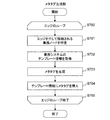
- FIG. 20 is a flowchart illustrating an example of the monitoring process according to the first embodiment.
- the business system monitoring unit 313 included in the control unit 201 executes monitoring processing.
- the business system monitoring unit 313 When the business system monitoring unit 313 detects the start timing of the process, the business system monitoring unit 313 starts the monitoring process (step S500). For example, when the business system monitoring unit 313 periodically executes the monitoring process, the business system monitoring unit 313 starts the monitoring process when detecting that a certain time has elapsed. In addition, the business system monitoring unit 313 starts monitoring processing when receiving an instruction from the user.
- the business system monitoring unit 313 reads the system performance table 326 and the influence range data, and monitors the state of the business node included in the influence range in the business system based on the read information (step S501).
- the business system monitoring unit 313 acquires the status of the business node at predetermined time intervals.
- the state of the business node included in the influence range is monitored, but only the state of the important node may be monitored.
- a monitoring target only a specific parameter may be monitored, or all parameters may be monitored.
- the business system monitoring unit 313 displays the load of the business node included in the affected range as a meter representing the load ratio (step S502). That is, the risk level indicating the possibility that the computer resources allocated to the business node will be insufficient is displayed as a meter. Specifically, the following processing is executed.
- the business system monitoring unit 313 refers to the system performance table 326 and searches for an entry that matches the identifier of the important node included in the influence range data. Next, the performance characteristic function from the function 1106 in the row where the identifier stored in the related node identifier 1103 matches the identifier of the business node from which the load is acquired and the adjustment parameter type 1105 matches the parameter corresponding to the acquired load. To get.
- the business system monitoring unit 313 calculates the current load ratio with respect to the maximum load value from the performance characteristic function and the acquired load value of the business node.
- the maximum load value can be calculated based on the domain X and the performance characteristic function.
- the business system monitoring unit 313 displays a meter 15 as shown in FIG. 1 based on the calculated load ratio. The above is the description of the process in step S502.
- the business system monitoring unit 313 determines whether there is a business node with an increased load (step S503).
- the business system monitoring unit 313 determines whether there is a business node for which the load ratio calculated in step S502 is greater than a predetermined threshold. For example, it is determined whether there is a business node having a load ratio greater than 80%.
- the business system monitoring unit 313 may determine that there is a business node with an increased load when receiving an instruction to change the configuration of the business node from a user who viewed the display on the meter 15.
- the business system monitoring unit 313 returns to step S501 and continues monitoring the status of the business system.
- the business system monitoring unit 313 refers to the rule management table 328 and searches for a rule applicable to the business node (step S504). Specifically, the following processing is executed.
- the business system monitoring unit 313 refers to the node management table 323 to search for an entry in which the business node identifier 801 identifier matches the business node identifier specified in step S504.
- the business system monitoring unit 313 acquires values stored in the business type 804 and the business identifier 805 of the searched entry.
- the business system monitoring unit 313 refers to the rule management table 328, and an entry in which the business identifier 1401 matches the value acquired from the business identifier 805 and the business type 1403 matches the value acquired from the business type 804 Search for.
- step S504. the business system monitoring unit 313 executes the above-described processing for each business node.
- the business system monitoring unit 313 displays the rules retrieved from the rule management table 328 together with the alert (step S505), and then returns to step S501 to continue monitoring the business system.
- the business system monitoring unit 313 displays the content stored in the rule 1406 of the entry retrieved from the rule management table 328 and the numerical value set in the priority order 1405 to the user.
- the user can grasp the necessity of improving the performance of the business system and the contents of the change for improving the performance of the business system without grasping the detailed state of the configuration of the physical layer and the logical layer. .
- the business system monitoring unit 313 only displays the rules, but the business system configuration change processing may be executed based on the rules. Further, together with the rule, the cost information such as the charge when the rule is applied and the service stop time may be displayed together.
- the present invention is not limited to this.
- the present embodiment can also be applied to a system having a two-layer structure of a physical layer and a business layer. That is, the present embodiment can be applied to a system in which physical nodes are assigned to all business nodes.
- the logic layer may have a multi-stage configuration.
- a two-stage configuration may be employed in which a plurality of logical computers are configured by logically dividing the blade server 223 and a plurality of virtual computers are operated on each logical computer.
- the management server 100 identifies an important business node based on the configuration information of the physical layer and the logical layer, and estimates a performance limit of the business system by performing a load test on the important business node. be able to.
- the following can be considered.
- a specific business system is constructed on the computer system, and the management server 100 executes the node selection process, the measurement process, and the aggregation process, so that the performance limit of the computer system for the specific business system can be estimated.
- the management server 100 executes the monitoring process, so that the management cost of the user who operates the business system can be reduced.
- the weight calculation unit 310 calculates only the weight of the selected business node. However, the weight calculation unit 310 can also calculate the weight of the edge connecting the selected business node and another business node. Is possible.
- the logical node assigned to the selected business node forms a cluster with another logical node of the same physical server, and the business node to which the other logical node is assigned ( A case where the second business node) exists will be described as an example.
- step S201 the weight calculation unit 310 refers to the topology management table 320 and the logical configuration management table 321 based on the identifiers stored in the business node identifier 801 and the connection node identifier 806 of the entry corresponding to the selected business node. Then, it is determined whether or not a special connection relationship exists between the selected business node and another business node.
- step S202 when there is a special connection relationship, the weight calculation unit 310 calculates the eigenvalue stored in the system configuration 608 as the weight of the edge connecting the first business node and the second business node. .
- step S203 the weight calculation unit 310 registers the calculated edge weight in the weight management table 327. Specifically, the following processing is executed.
- the weight calculation unit 310 adds an entry to the weight management table 327 and sets a predetermined identifier as the identifier 1201 of the added entry.
- the weight calculation unit 310 sets “edge” as the type 1202 of the added entry, and sets the identifier of the first business node and the identifier of the second business node as the business node identifier 1204.
- the parameter type 1203 remains blank.
- the weight calculation unit 310 sets a conversion formula using the calculated edge weight as a weight coefficient for the added entry weight 1205.
- a conversion formula is set like the weight 1205 of the entry whose identifier 1201 is “102” in FIG.
- “0.8” is a weight coefficient
- “m” is an edge weight obtained from the measurement result. Since the edge weight is unknown at this time, the edge weight is set as a variable.
- it is not limited to a format as shown in FIG. 12, For example, the conversion formula containing addition, division, etc. may be sufficient.
- step S404 the estimation unit 312 calculates the corrected edge weight by substituting the calculated edge weight into the conversion formula stored in the weight 1205, and calculates the calculated edge weight. The weight is overwritten on the weight 1205.
- Example 2 In the measurement process of the first embodiment, the management server 100 measures the load on the business node for all the verification methods. However, there is a case where the adjustment parameter is self-evident or the measurement process needs to be speeded up.
- the user specifies adjustment parameters in advance.
- the second embodiment will be described focusing on the differences of the first embodiment.
- management server 100 configuration, and blade server 223 configuration of the second embodiment are the same as those of the first embodiment, description thereof is omitted.
- the contents of the management table group 202 included in the management server 100 according to the second embodiment are also the same as those according to the first embodiment, and a description thereof will be omitted.
- the node selection process, the aggregation process, and the monitoring process of the second embodiment are the same as those of the first embodiment, description thereof is omitted.
- Example 2 the processing content of the measurement process is partially different. Specifically, the measurement unit 311 displays a directional parameter registration screen 2100 for designating a verification method to be applied at the start of the measurement process to the user.
- the directional parameter registration screen 2100 will be described.
- FIG. 21 is an explanatory diagram illustrating an example of a directional parameter registration screen 2100 according to the second embodiment.
- a selection item display area 2110 On the directional parameter registration screen 2100, a selection item display area 2110, a registration button 2120, a registration content display area 2130, a setting button 2140, and a cancel button 2150 are displayed.
- the selection item display area 2110 is an area for displaying information for specifying an adjustment parameter.
- the selection item display area 2110 includes a business node selection item 2111 and a parameter-oriented selection item 2112.
- the business node selection item 2111 is an item for selecting an important node.
- the parameter-oriented selection item 2112 is an item for designating an adjustment parameter to be applied to the important node.
- the measuring unit 311 displays an important node in the business node selection item 2111 based on the verification list.
- the parameter-oriented selection item 2112 displays not only the adjustment parameter itself but also the condition of the adjustment parameter or the type of the adjustment parameter. For example, “processor oriented” or the like is displayed as a display for designating an adjustment parameter related to the processor.
- the business node selection item 2111 and the parameter-oriented selection item 2112 are displayed in a pull-down format.
- the registration button 2120 is an operation button for registering the operation content of the selection item display area 2110.
- the registration button 2120 When the user operates the registration button 2120, the content set in the selection item display area 2110 is displayed in the registration content display area 2130.
- the registration content display area 2130 is an area for displaying the setting contents of the selection item display area 2110.
- the registered content display area 2130 includes a business node identifier 2131 and a parameter orientation 2132.
- the business node identifier 2131 is an important node identifier.
- the parameter orientation 2132 is parameter orientation applied to important nodes.
- the setting button 2140 is an operation button for reflecting the content displayed in the registered content display area 2130 to the measurement process.
- measurement unit 311 starts the process of step S300.
- a cancel button 2150 is an operation button for canceling the content displayed in the registered content display area 2130.
- the measuring unit 311 When the setting button 2140 is operated, the measuring unit 311 temporarily stores the content displayed in the registered content display area 2130 in the work area of the memory 302. In addition, the measurement unit 311 identifies the verification method of the selected important node based on the content set using the directivity parameter registration screen 2100 (step S301).
- the measurement unit 311 has the adjustment parameter type 1004 associated with the processor among the verification methods registered in the adjustment method management table 325. Search only for things. Since other processes are the same as those in the first embodiment, description thereof is omitted.
- the management server 100 can execute a load test for only necessary adjustment parameters. As a result, it is possible to reduce the load of the measurement process and increase the speed of the measurement process.
- Example 3 in the node selection process, the management server 100 selects an important node using the configuration of the business layer and the configuration of the physical layer and the logical layer.
- the third embodiment will be described focusing on differences from the first embodiment.
- the configuration of the management server 100, and the configuration of the blade server 223 are the same as those of the first embodiment, description thereof is omitted. Since the contents of the management table group 202 included in the management server 100 of the third embodiment are also the same as those of the first embodiment, the description thereof is omitted. Moreover, since the measurement process, the total process, and the monitoring process are the same as those in the first embodiment, the description thereof is omitted. In the third embodiment, part of the node selection process is different from the first embodiment.
- the weight calculation unit 310 acquires the weight associated with the selected business node from the topology management table 320, the logical configuration management table 321 and the business management table 322 (step S200). S201).
- the method for acquiring eigenvalues from the topology management table 320 and the logical configuration management table 321 is the same as that in the first embodiment, and a description thereof will be omitted.
- a method by which the weight calculation unit 310 acquires the eigenvalues of the business node from the business management table 322 will be described.
- the weight calculation unit 310 refers to the business management table 322 and searches for an entry in which the business identifier 701 matches the business identifier 805 of the entry selected from the node management table 323.
- the weight calculation unit 310 acquires the value of the eigenvalue 706 of the searched entry.
- step S202 the weight calculation unit 310 calculates the weight of the business node using the unique values acquired from the topology management table 320, the logical configuration management table 321 and the business management table 322. Since other processes are the same as those in the first embodiment, description thereof is omitted.
- the third embodiment since it is possible to select an important node in consideration of business layer information, a more accurate business system performance limit can be estimated.
- the following can be considered as a providing method of the third embodiment.
- a new business system is constructed on the existing computer system, and the management server 100 executes the node selection process, the measurement process, and the aggregation process, whereby the performance limit of the business system with respect to the existing computer system can be estimated.
- the management server 100 executes the monitoring process, so that the management cost of the user who operates the business system can be reduced.
- Example 4 the management server 100 reflects the configuration of the business layer in the relevance matrix in the aggregation process.
- the configuration of the management server 100, and the configuration of the blade server 223 are the same as those of the first embodiment, description thereof is omitted.
- the contents of the management table group 202 included in the management server 100 according to the fourth embodiment are also the same as those according to the first embodiment, and a description thereof will be omitted.
- the node selection process, the measurement process, and the monitoring process of the fourth embodiment are the same as those of the first embodiment, description thereof is omitted.
- a part of the aggregation process is different from the first embodiment.
- step S400 The processing from step S400 to step S407 is the same as in the first embodiment.
- the estimation unit 312 generates an association matrix after selecting the adjustment parameter to be processed (step S408) (step S409). Specifically, the following processing is executed.
- the estimation unit 312 first generates an association matrix based on the weight management table 327 according to the same procedure as in the first embodiment. Next, the estimation unit 312 generates a superposition matrix based on the business layer configuration information. The estimation unit 312 reflects the superposition matrix in the relevance matrix. For example, the estimation unit 312 multiplies or adds the superposition matrix to the relevance matrix.
- step S410 the estimation unit 312 identifies the influence range based on the relevance matrix reflecting the superposition matrix.
- FIG. 22 is a flowchart illustrating an example of a superposition matrix generation process according to the fourth embodiment.
- the estimation unit 312 generates a matrix of n rows and n columns in which all matrix components are “0” (step S600).
- the estimation unit 312 sets the eigenvalue of the business node as the diagonal component (step S601).
- the estimation unit 312 selects one entry from the node management table 323, and acquires the value of the business identifier 805 of the selected entry.
- the estimation unit 312 refers to the business management table 322 and searches for an entry in which the business identifier 701 matches the value acquired from the business identifier 805.
- the estimation unit 312 acquires the value of the eigenvalue 706 of the searched entry, and sets the value of the eigenvalue 706 to the diagonal component of the matrix corresponding to the selected business node.
- the estimation unit 312 performs the above-described processing for all entries in the node management table 323, that is, for all business nodes. Thereby, the value of the diagonal component of the matrix is set.
- the estimation unit 312 starts a business node loop process (step S602). At this time, the estimation unit 312 selects one entry from the node management table 323.
- the estimation unit 312 identifies a related node connected to the business node corresponding to the selected entry (step S603). Specifically, the estimation unit 312 acquires the business node identifier from the connection node identifier 806 of the selected entry.
- the business node corresponding to the connection node identifier 806 is also referred to as a connection node.
- the estimation unit 312 starts loop processing of the identified connection node (step S604). At this time, the estimation unit 312 selects one identifier of the connection node to be processed from the identifiers of the acquired connection nodes.
- the estimation unit 312 confirms the configuration related to the business node and the connection node (step S605), and determines whether or not there is a special connection relationship between the business node and the connection node (step S606). Specifically, the following processing is executed.
- the estimation unit 312 first checks the configuration of the business node.
- the estimation unit 312 refers to the entry corresponding to the business node in the node management table 323, acquires the value of the assigned node identifier 803 and the value of the business identifier 805, and acquires the information of the related information 807.
- the estimation unit 312 refers to the business management table 322 and searches for an entry in which the value of the business identifier 701 matches the value acquired from the business identifier 805.
- the estimation unit 312 acquires the eigenvalue 706 of the searched entry.
- the estimation unit 312 identifies the node assigned to the business node based on the value acquired from the assigned node identifier 803.
- the estimation unit 312 When a physical node is assigned to the business node, the estimation unit 312 refers to the topology management table 320 and searches for an entry in which the value of the physical node identifier 503 matches the value of the assigned node identifier. The estimation unit 312 acquires information from the reliability type 507 of the searched entry, and acquires a value from the eigenvalue 508.
- the estimation unit 312 refers to the logical configuration management table 321 and searches for an entry in which the value of the logical node identifier 603 matches the value of the assigned node identifier.
- the estimation unit 312 acquires information from the system configuration 608 of the searched entry, and acquires a value from the eigenvalue 610. Further, the estimation unit 312 refers to the topology management table 320 based on the value of the physical node identifier 607 of the retrieved entry, acquires information from the reliability type 507 of the entry corresponding to the physical node, and A value is acquired from the eigenvalue 508.
- connection node configuration The same process is executed for the connection node configuration.
- the estimation unit 312 analyzes the configuration of the business node and the connection node, and determines whether or not a special connection relationship exists. For example, when each of the business node and the connection node is a logical node that is generated on the same physical server and forms a cluster, the estimation unit 312 determines that a special connection relationship exists.
- step S605 The above is the description of the processing in step S605 and step S606.
- the estimation unit 312 proceeds to step S609.
- the estimation unit 312 calculates the eigenvalue of the edge using the eigenvalue acquired in step S605 (step S607).
- the estimation unit 312 calculates the eigenvalue of the edge using the eigenvalue acquired in step S605 (step S607).
- a method of calculating the eigenvalue of the edge by adding the eigenvalue 610 value related to the business node and the eigenvalue 610 value related to the connection node can be considered. Note that the present embodiment is not limited to the method for calculating the eigenvalue of the edge.
- the estimation unit 312 sets the calculated eigenvalue of the edge as a diagonal component corresponding to the edge (step S608).
- the estimation unit 312 determines whether or not the processing has been completed for all the connection nodes identified in step S603 (step S609). If it is determined that the processing has not been completed for all the connection nodes identified in step S603, the estimation unit 312 returns to step S604 and executes the same processing for the new connection node.
- the estimation unit 312 determines whether the processing has been completed for all business nodes (step S610).
- the estimation unit 312 If it is determined that the processing has not been completed for all business nodes, the estimation unit 312 returns to step S602 and executes the same processing for the new business node. On the other hand, when it is determined that the processing has been completed for all the business nodes, the estimation unit 312 ends the processing.
- the fourth embodiment it is possible to estimate the performance limit of the business system in consideration of information on the physical layer, the logical layer, and the business layer.
- the providing method similar to Example 3 can be considered.
- the management server 100 incorporates the influence range data into the template information used when building the business system.
- the configuration of the business system is managed as template information.
- the template information is data in XML format, for example. Therefore, the management server 100 incorporates the result of the aggregation processing into the template information corresponding to the business system for which the load test has been performed.
- the management server 100 according to the fifth embodiment is partially different in configuration.
- FIG. 23 is a block diagram illustrating a configuration example of the management server 100 according to the fifth embodiment.
- control unit 201 includes a meta tag insertion unit 2301. Further, the management table group 202 of the fifth embodiment includes template management information 2302.
- Template management information 2302 stores information related to the configuration of the business system. Specifically, the template management information 2302 includes a plurality of entries associated with business system identification information and template information indicating the configuration of the business system. In this embodiment, the template information is assumed to be XML format data.
- the meta tag insertion unit 2301 generates a meta tag (meta information) based on the result of the aggregation process, and inserts it into the meta tag of the template information. Details of processing executed by the meta tag insertion unit 2301 will be described later with reference to FIG.
- FIG. 24 is a flowchart illustrating an example of a meta tag generation process according to the fifth embodiment.
- the meta tag insertion unit 2301 of the control unit 201 starts the meta tag generation process after the aggregation process is completed.
- the meta tag insertion unit 2301 starts edge loop processing (step S700). At this time, the meta tag insertion unit 2301 refers to the weight management table 327 and selects one entry in which “edge” is stored in the type 1202.
- the meta tag insertion unit 2301 identifies two business nodes connected via the edge corresponding to the selected entry (step S701).
- the meta tag insertion unit 2301 refers to the business node identifier 1204 of the selected entry, and identifies two business nodes connected via the edge corresponding to the entry.
- the meta tag insertion unit 2301 acquires template information corresponding to the business system for which the load test has been performed, from the template management information 2302 (step S702).
- the meta tag insertion unit 2301 generates a meta tag related to an edge and a meta tag related to two business nodes connected via the edge (step S703). For example, the following meta tag is generated.
- the meta tag insertion unit 2301 generates a meta tag including edge information and a meta tag including information on two business nodes.
- the meta tag insertion unit 2301 refers to the system performance table 326 and generates a meta tag indicating the performance limit values in the two business nodes.
- the meta tag insertion unit 2301 searches for a row in which the important node identifier 1102 and the related node identifier 1103 match the identifiers of the two business nodes, and acquires a function stored in the function 1106 of the row. Further, a value X at which the system response time is saturated is calculated from the function, and a meta tag including a percentile of the value is generated.
- the meta tag insertion unit 2301 inserts the generated meta tag into the acquired template information (step S704).
- the meta tag insertion unit 2301 determines whether or not processing has been completed for all edges (step S705).
- the meta tag insertion unit 2301 returns to step S700 and executes the same processing for the new edge.
- the meta tag insertion unit 2301 ends the processing.
- the measurement result of the business system load test can be inserted into the template information used when the business system is generated.
- the performance characteristics of the business system can be grasped at the time of construction of the business system, and the system configuration necessary for construction of the business system can be grasped.
- meta tags include methods for dealing with any of physical nodes, logical nodes, and business nodes, when a performance failure occurs in a computer system or business system, quick and accurate failure handling based on the meta tag Is possible.
- this invention is not limited to the above-mentioned Example, Various modifications are included.
- the above-described embodiments have been described in detail for easy understanding of the present invention, and are not necessarily limited to those having all the configurations described.
- a part of the configuration of one embodiment can be replaced with the configuration of another embodiment, and the configuration of another embodiment can be added to the configuration of one embodiment.
- each of the above-described configurations, functions, processing units, processing means, and the like may be realized by hardware by designing a part or all of them with, for example, an integrated circuit.
- Each of the above-described configurations, functions, and the like may be realized by software by interpreting and executing a program that realizes each function by the processor.
- Information such as programs, tables, and files that realize each function is non-temporary that can be read by a storage device such as a memory, hard disk, SSD (Solid State Drive), or a computer such as an IC card, SD card, or DVD. Can be placed on any storage medium.
- control lines and information lines indicate what is considered necessary for the explanation, and not all the control lines and information lines on the product are necessarily shown. Actually, it may be considered that almost all the components are connected to each other.
Abstract
計算機システムに接続された管理計算機におけるシステム管理方法であって、計算機システムは複数の計算機を含み、計算機システムには業務システムが構築され、業務システムは、計算機又は仮想計算機が有する計算機リソースが割り当てられた業務ノードを複数含み、システム管理方法は、管理計算機が、計算機システムの構成を解析して、業務システムにおいて重要な業務ノードである重要ノードを一つ以上特定するステップと、一つ以上の重要ノードに割り当てられる計算機リソースの割当量を変更して、業務システムの負荷を計測するステップと、負荷の計測結果に基づいて、複数の業務ノード間の関連性の強さを示す重みを算出するステップと、重みに基づいて、一つ以上の重要ノードの負荷の変化によって影響を受ける範囲を特定するステップと、を含む。
Description
本発明は、複数の計算機を含む計算機システム上に構築された業務システムの管理方法に関する。
近年のクラウドコンピューティングの進展に伴い、計算機リソースをリソースプールとして運用するデータセンタが増えている。データセンタのプロバイダは、ユーザの要求に応じてリソースプールから所定の計算機リソースを割り当て、ユーザの業務システムをデータセンタ上に構築する。ユーザはデータセンタ上に構築された業務システムを用いて、Webサービスなど所定のサービスを提供する。
プロバイダは、リソースプールを運用において、データセンタにおけるシステムの性能限界を把握し、必要に応じてデータセンタの規模を拡張していくことが重要である。一般的には、スケールアウトによってデータセンタの計算機リソースを増設することによって、データセンタの規模が拡張される。
計算機システムの管理方法は、例えば、特許文献1に記載されている。特許文献1には、「契約条件を満たすように監視対象システムを制御するために用いられ、前記監視対象システムの状態を示す条件と、前記監視対象システムの状態が当該条件を満たす場合に実行されるアクションとを含むポリシの作成を支援するポリシ作成支援システムにおけるポリシ作成支援方法であって、前記条件には、前記監視対象システムにおいて監視対象となる監視項目および当該監視項目における計測値の範囲が含まれ、前記ポリシ作成支援システムは、ポリシの作成に必要な監視項目の種別を指定するテンプレートを保持する保持ステップと、前記テンプレートで指定される種別に該当する監視項目のそれぞれについて、拡張対象となるリソースのリソース量毎の計測値を取得する取得ステップと、前記テンプレートで指定される種別に該当する監視項目のそれぞれについて、リソース量毎に、計測値の中から代表計測値を1つ選択する選択ステップと、前記テンプレートで指定される種別に該当する監視項目毎に、選択した代表計測値を含む範囲を計測値の範囲として、当該監視項目、当該監視項目におけるリソース量、および当該リソース量に対応する計測値の範囲を出力する出力ステップとを実行する」ポリシ作成支援方法が記載されている。
しかし、計算機システム及び業務システムはそれぞれ独立しており、また、業務システムの構成はユーザ毎に異なっていることから、容易に計算機システム及び業務システムの性能限界を把握することができない。そのため、スケールアウトの限界を見積もり、また、増設の単位を見積もることが困難である。また、どのような拡張を行うかは計算機システム及び業務システムの構成に依存する。
また、データセンタの計算機リソースの性能が一様でない場合、データセンタ内にクラスタリングが構成される場合、又は、安価なサーバのみからデータセンタが構成される場合等、データセンタ毎にシステム変更の対応方法が異なる。業務システムの構成にも同様の課題がある。したがって、単純なスケールアウトでは対応できないデータセンタにおいては、計算機システム及び業務システムの性能限界を見積もることが困難である。
本発明は、業務システムを構成する複数のノードの各々の関連性に基づいて効果的な負荷テストを行い、計算機システム及び業務システムの性能限界を見積もることを一つの目的とする。
本願において開示される発明の代表的な一例を示せば以下の通りである。すなわち、計算機システムに接続された管理計算機におけるシステム管理方法であって、前記管理計算機は、第1のプロセッサ、前記第1のプロセッサに接続される第1のメモリ、及び前記第1のプロセッサに接続される第1のインタフェースを備え、前記計算機システムは、複数の計算機を含み、前記複数の計算機の各々は、第2のプロセッサ、前記第2のプロセッサに接続される第2のメモリ、及び前記第2のプロセッサに接続される第2のインタフェースを備え、前記計算機システムには、業務システムが構築され、前記業務システムは、前記複数の計算機のうちの一つの計算機が有する計算機リソース又は前記複数の計算機の少なくとも一つの計算機上に生成された仮想計算機が有する計算機リソースが割り当てられた業務ノードを複数含み、前記システム管理方法は、前記管理計算機が、前記計算機システムの構成を解析して、前記業務システムにおいて重要な業務ノードである重要ノードを一つ以上特定する第1のステップと、前記管理計算機が、一つ以上の前記重要ノードに割り当てられる前記計算機リソースの割当量を変更して、前記業務システムの負荷を計測する第2のステップと、前記管理計算機が、前記負荷の計測結果に基づいて、前記複数の業務ノード間の関連性の強さを示す第1の重みを算出する第3のステップと、前記管理計算機が、前記算出された第1の重みに基づいて、前記一つ以上の重要ノードの負荷の変化によって影響を受ける範囲を特定する第4のステップと、を含むことを特徴とする。
本発明の一形態によれば、業務システムが構築される計算機システムの構成に基づいて重要ノードを特定し、重要ノードに着目して業務システムの負荷を計測できる。また、業務ノード間の関連性の強さに基づいて、重要ノードの影響を受ける範囲を特定できる。これによって、業務システムの性能限界を見積もることができる。
上記した以外の課題、構成及び効果は、以下の実施例の説明により明らかにされる。
図1は、本実施例の概要を説明するブロック図である。
図1には、所定の業務を実行する業務システムと、業務システムを管理する管理サーバ100とが管理ネットワークを介して接続される。また、業務システムは業務ネットワークを介して外部のネットワークと接続される。
図1に示す業務システムは、一つのデータベースサーバ10、二つのアプリケーションサーバ11、四つのWebサーバ12、及び一つのロードバランサ13から構成される。以下の説明では、業務システムを構成するデータベースサーバ等の構成を業務ノードとも記載する。
業務システムは、計算機リソースを提供する計算機システム上に構築される。計算機システムは、物理計算機及び物理スイッチ等から構成される物理層と、物理計算機を用いて実現される仮想計算機及び物理スイッチを用いて実現される仮想スイッチ等から構成される論理層とを含む。以下の説明では、物理層を構成する物理計算機等を物理ノードと記載し、論理層を構成する仮想計算機等を論理ノードとも記載する。
業務ノードは、物理ノード及び論理ノードを用いて実現される。例えば、データベースサーバ10を実現する場合、物理ノードであるブレードサーバ223を用いてデータベースサーバを実現してもよいし、ブレードサーバ223上に生成された仮想計算機、すなわち、論理ノードを用いてデータベースサーバを実現してもよい。
本実施例は、業務システムの性能限界を見積もることを目的とする。そのために、以下のような手順にしたがって業務システムにおける性能の要件が厳しい業務ノードを特定し、特定された業務ノードに対して負荷テストを行う。
(1)管理サーバ100が、まず、業務システムの構成、及び業務システムが構築される計算機システムの構成に基づいて、業務システムにおいて重要な業務ノードを特定する。以下の説明では重要な業務ノードを重要ノードとも記載する。
(2)管理サーバ100は、重要ノードに対して負荷テストを行い、業務システム全体の影響を計測する。
(3)管理サーバ100は、前述した負荷テストの計測結果に基づいて、業務システムにおいて大きな影響を与えるノードの組合せである最小カットセット(影響範囲)を算出する。なお、最小カットセットには、一つ以上の重要ノードが含まれる。また、管理サーバ100は、重要ノードの負荷の変化によって、影響範囲に含まれる業務ノードに与える影響の大きさを見積もる。
以上のような処理によって、業務システムの性能限界(性能特性)を見積もることができる。
図1に示す例では、重要ノードとして特定されたデータベースサーバの割当リソース量を30パーセント削減した場合の負荷テストの計測結果を示す。この場合、点線で示すような最小カットセットが算出される。すなわち、業務システムにおいて、重要ノードであるデータベースサーバの負荷の影響を受ける業務ノードを特定できる。
また、本実施例では、管理サーバ100が、業務システムの運用時に負荷テストの計測結果に基づく監視処理を実行する。このとき、管理サーバ100は、影響範囲に含まれる業務ノードの負荷の推定値、又は危険値等を示すメータ15を表示する。これによって、計算機システム及び業務システムの拡張が必要であるか否かを推定できる。
これによって、業務システムの負荷が一定以上になる前に、プロバイダ又はユーザにアラートを通知することができるため、予め対応策をたてることができる。
(実施例1)
図2は、実施例1のシステム全体の構成の一例を示す説明図である。
図2は、実施例1のシステム全体の構成の一例を示す説明図である。
実施例1におけるシステムは、管理サーバ100、及び業務システムが構築される計算機システムから構成される。計算機システムは、計算機リソースを提供するシステムであり、複数のサーバ装置220、ストレージサブシステム260、NW-SW250、及びFC-SW140から構成される。
管理サーバ100は、計算機システムを管理する。管理サーバ100は、NW-SW(管理用ネットワークスイッチ)210を介して、NW-SW210の管理インタフェース(管理I/F)211及びNW-SW(業務用ネットワークスイッチ)250の管理インタフェース251に接続されており、管理サーバ100は各NW-SW210、250に対してVLAN(Virtual LAN)を設定できる。
NW-SW210は、管理用のネットワークを構成する。管理用のネットワークは、管理サーバ100が複数のサーバ装置220上で稼動するOS及びアプリケーションの配布並びに電源制御等の運用管理をするためのネットワークである。
NW-SW250は、業務用のネットワークを構成する。業務用のネットワークとは、サーバ装置220又はサーバ装置220上の仮想計算機(VM)が実行するアプリケーションによって使用されるネットワークである。なお、NW-SW250は、WAN等を介して接続される外部のクライアント計算機と通信する。
以下の説明では、サーバ装置220、FC-SW140、NW-SW250及びストレージサブシステム260等の物理的な計算機リソースを物理ノードと呼び、VM及び仮想スイッチ等の仮想的な計算機リソースを論理ノードと呼ぶ。
管理サーバ100は、FC-SW(ファイバーチャネル スイッチ)140を介してストレージサブシステム260の管理インタフェース(管理I/F)161に接続される。管理サーバ100は、ストレージサブシステム260内のLU(Logical Unit)162を管理する。図1に示す例では、管理サーバ100は、N個のLU1~LUnを管理する。
管理サーバ100は、制御部201を備え、また、管理テーブル群202を保持する。管理テーブル群202は、計算機システムの構成情報等を含む。制御部201は、管理テーブル群202に含まれる情報を参照して、計算機システム上に構築された業務システムに対して負荷テスト(ブラックボックステスト)を実行し、また、負荷テストの計測結果に基づいて管理テーブル群202に含まれる情報を更新する。管理サーバ100の構成の詳細については図3を用いて後述する。
サーバ装置220は、後述するように業務ノードに割り当てる計算機リソースを提供する。サーバ装置220は、I/Oデバイス等を介して、NW-SW210、250に接続される。
サーバ装置220は、サービスプロセッサ221及び複数のブレードサーバ223を搭載する。サービスプロセッサ221は、サーバ装置220に搭載されるブレードサーバ223を監視する。サーバ装置220はサービスプロセッサ221を介して管理サーバ100と接続する。ブレードサーバ223は、OS及びアプリケーションが稼動する。ブレードサーバ223のソフトウェア構成及びハードウェア構成については図4を用いて後述する。
なお、ブレードサーバ223には一つ以上のVMを生成することができる。また、FC-SW及びNW-SW250には一つ以上の仮想スイッチを生成することができる。ブレードサーバ223上に仮想スイッチが生成されてもよい。
なお、サーバ装置220はブレードサーバ223を備えるが、本実施例はこれに限定されない。例えば、プロセッサ、メモリ、ネットワークインタフェース等を備える一般的な計算機をサーバ装置220として用いてもよい。
ストレージサブシステム260は、サーバ装置220上で稼動するOS等が使用する記憶領域を提供する。ストレージサブシステム260は、コントローラ(図示省略)、複数の記憶媒体(図示省略)、ディスクインタフェース(図示省略)、及びネットワークインタフェース(図示省略)を備える。記憶媒体としてはHDD(Hard Disk Drive)及びSSD(Solid State Drive)等が考えられる。
コントローラ(図示省略)は、複数の記憶媒体(図示省略)を用いてRAIDを構成し、RAIDボリュームから複数のLU162を生成する。ストレージサブシステム260は、LU162をOS等が使用する記憶領域として提供する。
図3は、実施例1の管理サーバ100の構成例を示すブロック図である。
管理サーバ100は、プロセッサ301、メモリ302、ディスクインタフェース303、及びネットワークインタフェース304を有する。
プロセッサ301は、メモリ302に格納されるプログラムを実行する。メモリ302は、プロセッサ301によって実行されるプログラム及び当該プログラムの実行に必要な情報を格納する。メモリ302に格納されるプログラム及び情報については後述する。
ディスクインタフェース303は、ストレージサブシステム260にアクセスするためのインタフェースである。ネットワークインタフェース304は、IPネットワークを介して他の装置と通信するためのインタフェースである。
なお、図示しないが、管理サーバ100は、電源制御及び各インタフェースの制御を行うBMC(Basement Management Controller)を有してもよい。
メモリ302には、制御部201を実現するプログラム及び管理テーブル群202が格納される。制御部201は、複数のプログラムモジュールから構成される。具体的には、制御部201は、重み算出部310、計測部311、推定部312、及び業務システム監視部313を含む。
プロセッサ301は、重み算出部310、計測部311、推定部312、及び業務システム監視部313を実現するプログラムモジュールに従って動作することによって、所定の機能を実現する機能部として動作する。例えば、プロセッサ301は、重み算出部310を実現するプログラムモジュールに従って動作することによって重み算出部310として機能する。他のプログラムについても同様である。
重み算出部310は、業務システムにおける複数の業務ノードの各々の重要度を評価するための重みを算出する。実施例1の重み算出部310は、物理的な計算機リソース(物理ノード)の構成及び論理的な計算機リソース(論理ノード)の構成に基づいて、業務ノードの重みを算出する。重み算出部310が実行する処理の詳細は、図16を用いて後述する。
計測部311は、業務ノードに対して所定の負荷テスト(ブラックボックステスト)を実行することによって業務システムにおける影響を計測する。計測部311が実行する処理の詳細は、図17を用いて後述する。
推定部312は、計測結果に基づいて、業務システムの性能限界を見積もるための情報を生成する。推定部312が実行する処理の詳細は、図19を用いて後述する。
業務システム監視部313は、業務システムの性能限界に関する情報に基づいて業務システムの監視し、監視の結果を表示する。また、業務システム監視部313は、重み算出部310、計測部311、及び推定部312の処理結果を表示してもよい。業務システム監視部313が実行する処理の詳細は、図20を用いて後述する。
管理テーブル群202は、計算機システム及び業務システムを管理するための各種情報を格納する。具体的には、管理テーブル群202は、トポロジ管理テーブル320、論理構成管理テーブル321、業務管理テーブル322、ノード管理テーブル323、閾値管理テーブル324、調整方法管理テーブル325、システム性能テーブル326、重み管理テーブル327、及びルール管理テーブル328を含む。
なお、ノード管理テーブル323、システム性能テーブル326及び重み管理テーブル327は、業務システム毎に一つのテーブルが存在するものとする。
トポロジ管理テーブル320は、物理ノードに関する情報を格納する。トポロジ管理テーブル320の詳細は、図5を用いて後述する。論理構成管理テーブル321は、論理ノードに関する情報を格納する。論理構成管理テーブル321の詳細は、図6を用いて後述する。業務管理テーブル322は、業務システムにおいて実行されるプログラムに関する情報を格納する。業務管理テーブル322の詳細は、図7を用いて後述する。ノード管理テーブル323は、業務ノードに関する情報を格納する。ノード管理テーブル323の詳細は、図8を用いて後述する。
閾値管理テーブル324は、業務ノードの重みに基づいて、重要ノードを選択するための閾値を格納する。閾値管理テーブル324の詳細は、図9を用いて後述する。調整方法管理テーブル325は、負荷テストのポリシを格納する。調整方法管理テーブル325の詳細は、図10を用いて後述する。
システム性能テーブル326は、負荷テストの計測結果を格納する。システム性能テーブル326の詳細は、図11を用いて後述する。重み管理テーブル327は、業務ノードの重要度、及び業務システムにおける業務ノード間の関連性に関する情報を格納する。重み管理テーブル327の詳細は、図12を用いて後述する。
ルール管理テーブル328は、業務システム又は計算機システムの構成を変更方法及び変更内容を格納する。ルール管理テーブル328の詳細は、図14を用いて後述する。
制御部201を実現するプログラム及び管理テーブル群202における各テーブルは、ストレージサブシステム260、不揮発性半導体メモリ、ハードディスクドライブ若しくはSSD(Solid State Drive)等の記憶デバイス、又は、ICカード、SDカード若しくはDVD等の計算機が読み取り可能な非一時的データ記憶媒体に格納することができる。
なお、管理サーバ100のサーバの種別については、物理サーバ、ブレードサーバ、仮想化されたサーバ、論理分割又は物理分割されたサーバなどのいずれであってもよく、いずれのサーバを使った場合でも本実施例の効果を得ることができる。
図4は、実施例1のブレードサーバ223の構成例を示すブロック図である。
ブレードサーバ223は、プロセッサ401、メモリ402、ネットワークインタフェース403、ディスクインタフェース404、BMC405、及びPCI-Expressインタフェース406を有する。
プロセッサ401は、メモリ402に格納されるプログラムを実行する。メモリ402は、プロセッサ401によって実行されるプログラム及び当該プログラムを実行するために必要な情報を格納する。メモリ302に格納されるプログラム及び情報については後述する。
ネットワークインタフェース403は、IPネットワークを介して他の装置と通信するためのインタフェースである。ディスクインタフェース404は、ストレージサブシステム260にアクセスするためのインタフェースである。
BMC405は、電源制御及び各インタフェースの制御を行う。PCI-Expressインタフェース406は、PCIex-SWに接続するためのインタフェースである。
メモリ402には、OS411、アプリケーション421及び監視部422を実現するプログラムが格納される。プロセッサ401が、メモリ402上のOS411を実行することによって、ブレードサーバ223内のデバイスを管理する。OS411の下で、業務を提供するアプリケーション421及び監視部422が動作する。
なお、メモリ402は、後述するように仮想計算機を管理する仮想化部を実現するプログラムを格納していてもよい。
なお、図4に示す例では、ネットワークインタフェース403、ディスクインタフェース404及びPCI-Expressインタフェース406を、それぞれ一つずつ示しているが、各インタフェースは複数あってもよい。例えば、ブレードサーバ223は、NW-SW210と接続するネットワークインタフェース、及びNW-SW250と接続するネットワークインタフェースを有してもよい。
図5は、実施例1のトポロジ管理テーブル320の一例を示す説明図である。
トポロジ管理テーブル320は、業務システムが構築される計算機システムの物理構成に関する情報を格納する。具体的には、トポロジ管理テーブル320は、識別子501、UUID502、物理ノード識別子503、デバイス名504、プロパティ505、接続先デバイス名506、信頼性種別507、及び固有値508を含む。
識別子501は、トポロジ管理テーブル320におけるエントリを一意に識別するための識別子である。UUID502は、重複しないように形式が規定された識別子であるUUID(Universal Unique IDentifier)を格納する。物理ノード識別子503は、物理層を構成する物理ノードを一意に識別するための識別子である。本実施例では、装置の識別子が物理ノードの識別子として用いられる。
デバイス名504は、物理ノードが備えるデバイスを一意に識別するための識別子である。物理ノードそのものを表すエントリの場合、デバイス名504は空欄となる。
プロパティ505は、物理ノードそのものの性能、又は、デバイス名504に対応するデバイスの性能を示す情報である。デバイス名504にFC-SW240のポート名が格納される場合、プロパティ505にはベンダ種別、RAID構成、仮想化種別、サポート機能、及びファームウェアバージョンなどの情報が格納される。
接続先デバイス名506は、デバイス名504に対応するデバイスと接続される他のデバイスの情報を格納する。なお、デバイス名504が空欄の場合、すなわち、物理ノードそのものに対応するエントリの場合、接続先デバイス名506には、物理ノードと接続される他の物理ノードの識別子が格納される。信頼性種別507は、物理ノード又は接続先デバイス名506に対応するデバイスの冗長化等の構成に関する情報である。
固有値508は、エントリに対応する物理ノード又はデバイスの重要度を評価するための値である。すなわち、固有値508は、計算機システムにおける物理層の構成の重要度を評価するための値である。ここで、物理層の構成には、物理ノードのハードウェア構成、ソフトウェア構成、及び複数の物理ノード間の接続構成などが含まれる。固有値508は予め設定されていてもよいし、管理サーバ100を操作する管理者等が設定してもよい。
図6は、実施例1の論理構成管理テーブル321の一例を示す説明図である。
論理構成管理テーブル321は、業務システムにおけるノードの特性に関する情報を格納する。具体的には、論理構成管理テーブル321は、識別子601、UUID602、論理ノード識別子603、種別604、調整メトリクス605、調整パラメタ606、物理ノード識別子607、システム構成608、縦列接続609、及び固有値610を含む。
識別子601は、論理構成管理テーブル321におけるエントリを一意に識別するための識別子である。論理ノード識別子603は、論理層を構成する論理ノードを一意に識別するための識別子である。本実施例では、VM及び仮想スイッチそのものの識別子が論理ノードの識別子として用いられる。種別604は、論理ノードが対応可能な性能変更方法の種別を示す情報である。
調整メトリクス605は、ブラックボックステストにおいて論理ノードの負荷を把握するために計測される項目である。例えば、識別子601「1」のエントリの調整メトリクス605には「CPU」、「I/O」及び「メモリ」が格納されるため、論理ノード1におけるプロセッサの使用率、I/O数又はメモリ使用率などが計測対象となる。調整パラメタ606は、ブラックボックステストにおいて論理ノードに対する負荷を変化させる場合に調整するパラメタである。
物理ノード識別子607は、論理ノードに計算機リソースを割り当てている物理ノードの識別子である。物理ノード識別子607は、物理ノード識別子503と同一のものである。
システム構成608は、論理層における論理ノードの構成に関する情報である。図6に示す例では、システム構成608にはシステムの構成を示す情報として「スケールアウト型」、「スケールアップ型」、及び「メッシュ型」が格納される。例えば、「スケールアウト型」は同一種類の論理ノードが並列して処理を行う構成であることを示す。また、システム構成608には、論理層における論理ノードの構成に対する固有値が設定される。例えば、識別子601が「1」のエントリのシステム構成608には固有値として「1.0」が設定される。また、システム構成608は、クラスタを構築する論理ノードの識別子、又は、並列に接続される論理ノードの識別子などが格納される。
縦列接続609は、論理ノード識別子603に対応する論理ノードと、直列構成によって接続される論理ノードの識別子である。直列構成には例えばWeb3階層モデルなどが考えられる。固有値610は、論理ノード識別子603に対応する論理ノードの重要度を評価するための値である。すなわち、固有値610は、計算機システムにおける論理層の構成の重要度を評価するための値である。ここで、論理層の構成には、論理ノードのハードウェア構成、ソフトウェア構成、及び複数の論理ノード間の接続構成などが含まれる。固有値610は予め設定されていてもよいし、管理サーバ100を操作する管理者等が設定してもよい。
図7は、実施例1の業務管理テーブル322の一例を示す説明図である。
業務管理テーブル322は、業務システムにおいて実行される業務に関する情報を格納する。具体的には、業務管理テーブル322は、業務識別子701、UUID702、業務ソフトウェア名703、業務設定情報704、優先順位705、及び固有値706を含む。
業務識別子701は、業務システムにおける業務を一意に識別するための識別子である。業務ソフトウェア名703は、業務を提供するために実行されるソフトウェアの名称である。業務設定情報704は、業務識別子701に対応する業務を実行するために必要な設定情報である。優先順位705は、業務システムにおける業務の優先順位である。優先順位705の値が小さいほど重要な業務であることを示す。また、優先順位705には、業務に必要な構成に関する情報も格納される。固有値706は、業務の重要度を評価するための値である。
図8は、実施例1のノード管理テーブル323の一例を示す説明図である。
ノード管理テーブル323は、業務システムを構成する業務ノードに関する情報を格納する。具体的には、ノード管理テーブル323は、業務ノード識別子801、UUID802、割当ノード識別子803、業務種別804、業務識別子805、接続ノード識別子806、及び関連情報807を含む。
業務ノード識別子801は、業務システムにおける業務ノードを一意に識別するための識別子である。
割当ノード識別子803は、業務ノードに計算機リソースを提供するノードの識別子である。物理ノードが業務ノードに計算機リソースを提供する場合、割当ノード識別子803には物理ノードの識別子が格納され、論理ノードが業務ノードに計算機リソースを提供する場合、割当ノード識別子803には論理ノードの識別子が格納される。
業務種別804は、業務ノードが実行する業務の種別である。業務識別子805は、業務種別804に対応する業務の識別子である。業務識別子805は、業務識別子701と同一のものである。接続ノード識別子806は、業務ノード識別子801に対応する業務ノードと接続される他の業務ノードの識別子である。関連情報807は、業務ノードに必要な構成に関する情報である。
図8に示すように、業務ノードには固有値が設定されていない。これは、同一の業務システムであっても、当該業務システムが構築される計算機システムの構成、及び業務システムにおいて実行される業務の内容の異なると、業務ノード間の関連、及び業務ノードの性能限界が異なるためである。
そこで、本実施例では、管理サーバ100が、物理層の構成及び論理層の構成、並びに、業務の内容に基づいて、業務ノードの重要度を示す重みを算出する。管理サーバ100は、算出された業務ノードの重みに基づいて、業務システムの重要ノードを特定する。
重要ノードは、業務システムに大きな影響を与える可能性が大きい。したがって、重要ノードを対象とする負荷テストを実行することによって効率的な計測が可能となる。また、重要ノードの負荷に対する業務システム全体の挙動を把握することによって、業務システムの性能限界を見積もることができる。なお、負荷テストは重要ノード以外の業務ノードに対して実行してもよい。例えば、重要ノードと接続される業務ノードに対して負荷テストを行う方法が考えられる。
本実施例は、重要ノードに限定して負荷テストを実行することによって計算効率を向上させ、かつ、負荷テストの精度を高めている。
本実施例では、一つの業務システムに対して一つのノード管理テーブル323が存在するものとする。ノード管理テーブル323には業務システムの識別子が対応付けられる。
図9は、実施例1の閾値管理テーブル324の一例を示す説明図である。
閾値管理テーブル324は、管理サーバ100が重要ノードを特定するときに使用する閾値を格納する。具体的には、閾値管理テーブル324は、識別子901、業務識別子902、及び閾値903を含む。
識別子901は、閾値管理テーブル324のエントリを一意に識別するための識別子である。業務識別子902は、業務システムにおける業務を一意に識別するための識別子である。業務識別子902は、業務識別子701と同一のものである。閾値903は、業務における閾値である。
本実施例では業務ごとに閾値を設定しているが、業務システムに対して一つ閾値が設定されてもよい。
図10は、実施例1の調整方法管理テーブル325の一例を示す説明図である。
調整方法管理テーブル325は、負荷テストにおいて物理ノード又は論理ノードに対する負荷の調整方法に関する情報を格納する。具体的には、調整方法管理テーブル325は、識別子1001、ノード種類1002、及び調整方法1003を含む。
識別子1001は、調整方法管理テーブル325のエントリを一意に識別するための識別子である。ノード種類1002は、調整対象のノードの種類である。ノード種類1002には「物理サーバ」、「SW」、「VM」、「vSW」等が格納される。
調整方法1003は、ノード種類1002に対応する物理ノード又は論理ノードに対する負荷の調整方法に関する情報を含む。具体的には、調整方法1003は、調整パラメタ種別1004、調整値1005、及び優先度1006を含む。
調整パラメタ種別1004は、ノード種類1002に対応するノードにおいて調整するパラメタ(調整パラメタ)の種別である。調整値1005は、調整パラメタの調整値である。優先度1006は、調整方法の優先順位である。より具体的には、ノード種類1002及び調整パラメタ種別1004が同一であり、かつ、調整値1005が異なるエントリが複数ある場合に適応する調整方法を決定するための値が格納される。本実施例では、値が小さいものほど優先順位が上位であるものとする。
ここで、調整方法の内容について説明する。
識別子1001が「1」のエントリのノード種類1002は「VM」であり、調整パラメタ種別1004は「CPU」であり、調整値1005は「-10%」である。この場合、管理サーバ100は、VMに割り当てられる仮想プロセッサの割当率を「-10%」だけ減少させ、業務システム全体の影響を計測する。以下、管理サーバ100は、「-10%」ずつ仮想プロセッサの割当率を減少させて、業務システム全体の影響を計測する。
識別子1001が「5」のエントリのノード種類1002は「VM」であり、調整パラメタ種別1004は「VM」であり、調整値1005は「-1」である。この場合、管理サーバ100は、VMの数を「-1」だけ減少させ、業務システム全体の影響を計測する。以下、管理サーバ100は、「-1」ずつVMの数を減少させて、業務システム全体の影響を計測する。
また、識別子1001が「6」のエントリのノード種類1002は「VM」であり、調整パラメタ種別1004は「CPU」であり、調整値1005は「vCPU -1 with reboot」である。この場合、管理サーバ100は、VMに対する仮想プロセッサの数を「-1」減少させ、かつ、再起動させた後に、業務システム全体の影響を計測する。以下、管理サーバ100は、「-1」ずつ仮想プロセッサの数を減少させ、かつ、再起動させた後、業務システム全体の影響を計測する。
なお、業務システムの負荷が急激に変化する場合には、さらに細かく値を調整するように設定してもよい。
図11は、実施例1のシステム性能テーブル326の一例を示す説明図である。
システム性能テーブル326は、負荷テストの計測結果に基づいて生成される性能特性関数に関する情報を格納する。具体的には、システム性能テーブル326は、識別子1101、重要ノード識別子1102、関連ノード識別子1103、及び性能特性関数1104を含む。
識別子1101は、システム性能テーブル326のエントリを一意に識別するための識別子である。システム性能テーブル326には、一つの重要ノードに対して一つのエントリが存在する。重要ノード識別子1102は、重要ノードである業務ノードの識別子である。関連ノード識別子1103は、重要ノードの影響を受ける業務ノードの識別子である。一つの重要ノードに対して関連ノードは一つ以上存在する。以下の説明では、重要ノードの影響を受ける業務ノードを関連ノードとも記載する。
性能特性関数1104は、重要ノードと関連ノードとの間の関係を示す性能特性関数に関する情報を格納する。具体的には、性能特性関数1104は、調整パラメタ種別1105及び関数1106を含む。
調整パラメタ種別1105は、重要ノードにおける調整パラメタであり、性能特性関数の変数に対応する。関数1106は、性能特性関数を格納する。本実施例では、性能特性関数は、調整パラメタに対する関連ノードの負荷の変化として算出される。関連ノードの負荷はプロセッサ使用率であるものとする。なお、メモリ使用率、ネットワーク使用率、レスポンスタイムなどを関連ノードの負荷として用いてもよい。
ここで、関数1106に格納される「X」は、調整パラメタ種別1105に対応する調整パラメタの値であり、「Y」は関連ノードの負荷を表す。
本実施例では、一つの業務システムに対して一つのシステム性能テーブル326が存在するものとする。システム性能テーブル326には業務システムの識別子が対応付けられる。
図12は、実施例1の重み管理テーブル327の一例を示す説明図である。図13は、実施例1の重み管理テーブル327を行列形式の表記例を示す説明図である。
重み管理テーブル327は、負荷テストの計測結果から算出される業務ノード間の関連性の強さに関する情報を格納する。具体的には、重み管理テーブル327は、識別子1201、種別1202、パラメタ種別1203、業務ノード識別子1204、及び重み1205を含む。
識別子1201は、重み管理テーブル327のエントリを一意に識別するための識別子である。種別1202は、重みが算出された対象の種別である。ノードの重みに対応するエントリの場合、種別1202には「ノード」が格納され、二つのノード間を接続するエッジの重みに対応するエントリの場合、種別1202には「エッジ」が格納される。パラメタ種別1203は、一方の業務ノードが他方の業務ノードに影響を与えるパラメタの種別を格納する。
業務ノード識別子1204は、種別1202に関連する業務ノードの識別子である。例えば、種別1202が「ノード」の場合、業務ノード識別子1204には一つの業務ノードの識別子が格納され、種別1202が「エッジ」の場合、当該エッジによって接続される二つの業務ノードの識別子が格納される。
重み1205は、業務ノードの重み又はエッジの重みである。ここで、業務ノードの重みは、業務システムにおける業務ノードの重要度を評価するための値である。エッジの重みは、業務ノード間の関連性の強さを評価するための値である。
図12に示す重み管理テーブル327は、図13に示すような行列形式のデータとして表現できる。ここで、行列の対角成分はノードの重み、行列の非対角成分はエッジの重みに対応する。例えば、行列成分A11は業務ノード1の重みに対応し、行列成分A12は、業務ノード1と業務ノード2との間を接続するエッジの重みに対応する。
重み管理テーブル327には、全ての行列要素のエントリが存在しない可能性がある。本実施例では、行列要素に対応するエントリが存在しない場合、当該行列要素の値は「0」であるものとする。
本実施例では、一つの業務システムに対して一つの重み管理テーブル327が存在するものとする。重み管理テーブル327には業務システムの識別子が対応付けられる。
図14は、実施例1のルール管理テーブル328の一例を示す説明図である。
ルール管理テーブル328は、業務システム又は計算機システムの構成を変更方法及び変更内容を格納する。具体的には、ルール管理テーブル328は、業務識別子1401、UUID1402、業務種別1403、関連情報1404、優先順位1405、及びルール1406を含む。
業務識別子1401は、業務システムにおける業務を一意に識別するための識別子である。業務識別子1401は、業務識別子701と同一のものである。業務種別1403は、業務ノードが実行する業務の種別である。業務種別1403は、業務種別804と同一のものである。関連情報1404は、業務種別に対応する業務に必要な構成に関する情報である。
優先順位1405は、業務システムにおける業務の優先順位である。本実施例では、優先順位1405の値が小さいほど優先順位が上位であるものとする。ルール1406は、業務システムの具体的な構成の変更内容である。本実施例では、ルール1406には、一つ以上の変更内容が格納される。この場合、全ての変更内容を適用してもよいし、業務システムの性能が向上したことが確認されるまで変更内容を適用してもよい。
図15は、実施例1の管理サーバ100が実行する処理の概要を説明するフローチャートである。
管理サーバ100の制御部201は、ユーザ等から負荷テストの実行指示を受け付けると処理を開始する。なお、管理サーバ100が処理を開始する契機はこれに限定されない。例えば、管理サーバ100は、周期的に処理を実行してもよいし、業務システム又は計算機システムの変更が検知された場合に処理を開始してもよい。管理サーバ100には、処理対象の業務システムの識別子が入力される。
制御部201は、まず、ノード選択処理を実行する(ステップS100)。ノード選択処理では、制御部201が、計算機システムの構成を解析し、解析結果に基づいて業務システムを構成する複数の業務ノードの中から一つ以上の重要ノードを選択する。ノード選択処理の詳細は、図16を用いて後述する。
制御部201は、計測処理を実行し(ステップS101)、計測処理の結果に基づいて集計処理を実行する(ステップS102)。計測処理では、ノード選択処理において選択された重要ノードに着目した負荷テストが実行される。集計処理では、計測処理の結果に基づいて、二つの業務ノード間の関連性を示す情報が生成される。計測処理の詳細については、図17を用いて後述する。また、集計処理の詳細については、図19を用いて後述する。
ステップS100からステップS102までの処理は、業務システムの運用前に実行される処理である。業務システムの運用が開始された後、制御部201は、計測処理及び集計処理の結果に基づいて、業務システムに対する監視処理を実行する(ステップS103)。監視処理の詳細は、図20を用いて後述する。
図16は、実施例1のノード選択処理の一例を説明するフローチャートである。制御部201に含まれる重み算出部310がノード選択処理を実行する。
重み算出部310は、業務ノードのループ処理を開始する(ステップS200)。このとき、重み算出部310は、業務システムに含まれる業務ノードの中から処理対象の業務ノードを選択する。
具体的には、重み算出部310は、入力された業務システムの識別子に対応するノード管理テーブル323を参照して、エントリを一つ選択する。本実施例では、重み算出部310は、ノード管理テーブル323の上のエントリから順に選択するものとする。なお、予め、業務種別又は業務内容に応じて優先順位を設定しておき、重み算出部310は当該優先順位に基づいてエントリを選択してもよい。
重み算出部310は、トポロジ管理テーブル320及び論理構成管理テーブル321から、選択された業務ノードに関連する固有値を取得する(ステップS201)。具体的には、以下のような処理が実行される。
重み算出部310は、ノード管理テーブル323から選択されたエントリの割当ノード識別子803を参照して、選択された業務ノードに計算機リソースを提供するノードを特定する。
業務ノードに計算機リソースを提供するノードが物理ノードである場合、重み算出部310は、トポロジ管理テーブル320を参照して、物理ノード識別子503が割当ノード識別子803と一致するエントリを全て検索する。重み算出部310は、検索されたエントリの固有値508の値を全て取得する。
業務ノードに計算機リソースを提供するノードが論理ノードである場合、重み算出部310は、論理構成管理テーブル321を参照して、論理ノード識別子603が割当ノード識別子803に一致するエントリを検索する。重み算出部310は、検索されたエントリのシステム構成608に含まれる値、及び固有値610の値を取得する。
さらに、重み算出部310は、トポロジ管理テーブル320を参照して、物理ノード識別子503が論理構成管理テーブル321から検索されたエントリの物理ノード識別子607と一致するエントリを全て検索する。重み算出部310は、検索されたエントリの固有値508を全て取得する。
なお、本実施例では、ブレードサーバ223等の物理ノードを業務ノードとして扱い、NW-SW250等の物理ノードは業務ノードとして扱っていない。業務層では、NW-SW250等の物理ノードはエッジとして扱われる。そのため、重み算出部310が固有値を算出する場合に、NW-SW250等の物理ノードを考慮する必要があるか否かを予め設定しておく必要がある。本実施例では、業務ノードに対して固有値の算出時に考慮する物理ノードが予め設定されているものとする。なお、エッジに含まれる物理ノードの固有値をエッジの重み係数として用いてもよい。
以上がステップS201の処理の説明である。
次に、重み算出部310は、トポロジ管理テーブル320及び論理構成管理テーブル321から取得された固有値を用いて、業務ノードの重みを算出する(ステップS202)。業務ノードの重みの算出方法は様々考えられるが、例えば以下のような算出方法が考えられる。
業務ノードに計算機リソースを提供するノードが物理ノードである場合、重み算出部310は、トポロジ管理テーブル320の固有値508から取得された全ての値を足しあわせることによって、第1の合計値を算出する。当該第1の合計値が、業務ノードの重みとなる。
業務ノードに計算機リソースを提供するノードが論理ノードである場合、重み算出部310は、トポロジ管理テーブル320の固有値508から取得された全ての値を足しあわせることによって、第1の合計値を算出する。また、重み算出部310は、論理構成管理テーブル321のシステム構成608に含まれる値と、固有値610の値とを足しあわせることによって、第2の合計値を算出する。さらに、重み算出部310は、第1の合計値と第2の合計値を足しあわせることによって、第3の合計値を算出する。当該第3の合計値が、業務ノードの重みとなる。
また、第2の合計値を重み係数として用いる方法も考えられる。この場合、重み算出部310は、第1の合計値に第2の合計値を乗算することによって、業務ノードの重みを算出する。
なお、前述した業務ノードの重みの算出方法は一例であって、本実施例は業務ノードの重みの算出方法に限定されない。また、物理層の構成及び論理層の構成から業務ノードの重要度を評価する指標(重み)を算出できる方法であればどのような方法であってもよい。
次に、重み算出部310は、算出された重みに基づいて重み管理テーブル327を更新する(ステップS203)。
具体的には、重み算出部310は、重み管理テーブル327にエントリを追加し、追加されたエントリの識別子1201に所定の識別子を設定する。重み算出部310は、追加されたエントリの種別1202に「ノード」を設定し、業務ノード識別子1204に処理対象の業務ノードの識別子を設定し、さらに、重み1205に算出された重みを設定する。なお、パラメタ種別1203は空欄のままである。
重み算出部310は、業務ノードの重みが閾値より大きいか否かを判定する(ステップS204)。
具体的には、重み算出部310は、閾値管理テーブル324を参照し、業務識別子902がノード管理テーブル323から選択されたエントリの業務識別子805と一致するエントリを検索する。重み算出部310は、業務ノードの重みが検索されたエントリの閾値903の値より大きいか否かを判定する。
業務ノードの重みが閾値903の値以下であると判定された場合、重み算出部310は、ステップS206に進む。
業務ノードの重みが閾値903の値より大きいと判定された場合、重み算出部310は、選択された業務ノードを検証リストに登録する(ステップS205)。ここで、検証リストは、重要ノードが登録されるリストである。
具体的には、重み算出部310は、選択された業務ノードのエントリを検証リストに登録する。本実施例では、重み算出部310は、論理構成管理テーブル321の業務ノードに対応するエントリと同一内容のエントリを検証リストに登録する。さらに、重み算出部310は、検証リストに格納されるエントリを業務ノードの重みに基づいてソートする。本実施例では、重み算出部310は、業務ノードの重みが大きい順にエントリを並び替える。
なお、検証リストが存在しない場合には、重み算出部310は、メモリ302のワークエリアに検証リストを生成し、生成された検証リストに業務ノードのエントリを登録する。
重み算出部310は、処理対象の業務システムの全ての業務ノードについて処理が完了したか否かを判定する(ステップS206)。処理対象の業務システムの全ての業務ノードについて処理が完了していないと判定された場合、重み算出部310は、ステップS200に戻り、新たな業務ノードに対して同様の処理を実行する。
処理対象の業務システムの全ての業務ノードについて処理が完了したと判定された場合、重み算出部310は、処理を終了する。
図17は、実施例1の計測処理の一例を説明するフローチャートである。制御部201に含まれる計測部311が計測処理を実行する。
計測部311は、重要ノードのループ処理を開始する(ステップS300)。このとき、計測部311は、検証リストから重要ノードのエントリを一つ選択する。本実施例の検証リストのエントリは重みが大きい順に並べられているため、計測部311は、検証リストの上位のエントリから順に選択する。また、計測部311は、システム性能テーブル326にエントリを追加し、識別子1101に所定の識別子を設定し、重要ノード識別子1102に選択された重要ノードの識別子を設定する。
計測部311は、調整方法管理テーブル325を参照して、選択された重要ノードに適用する検証方法を特定する(ステップS301)。具体的には、以下のような処理が実行される。
計測部311は、選択された重要ノードのエントリの割当ノード識別子803から識別子を取得する。
(1)取得された識別子が物理ノードの識別子である場合、計測部311は、物理ノードの識別子から装置を特定する。装置がブレードサーバ223である場合、計測部311は、調整方法管理テーブル325から、ノード種類1002が「物理サーバ」であるエントリを全て取得する。また、装置がスイッチである場合、計測部311は、調整方法管理テーブル325から、ノード種類1002が「SW」であるエントリを全て取得する。
(2)取得された識別子が論理ノードの識別子である場合、計測部311は、論理ノード識別子から論理的な装置を特定する。論理的な装置がVMである場合、計測部311は、調整方法管理テーブル325から、ノード種類1002が「VM」であるエントリを全て取得する。また、論理的な装置が仮想スイッチである場合、計測部311は、調整方法管理テーブル325から、ノード種類1002が「vSW」であるエントリを全て取得する。
さらに、計測部311は、トポロジ管理テーブル320を参照して、論理ノードが対応付けられる物理ノードを特定し、(1)において記載した方法と同様の方法を用いて、調整方法管理テーブル325から、物理ノードに対応するエントリを全て取得する。
以上がステップS301の処理の説明である。
次に、計測部311は、検証方法のループ処理を開始する(ステップS302からステップS309)。検証方法のループ処理では、計測部311が、特定された検証方法毎に、物理ノード又は論理ノードの少なくともいずれかのパラメタを調整し、業務システム全体の負荷を計測する。
まず、計測部311は、特定された検証方法を一つ選択し、選択された検証方法に基づいて計測処理を開始する(ステップS302)。このとき、調整パラメタ種別1004及び調整値1005が同一のエントリが複数存在する場合、計測部311は、優先度1006の値に基づいてエントリを選択する。
計測部311は、選択された検証方法にしたがって、物理ノード又は論理ノードのパラメタを変更し(ステップS303)、業務システムにおける各種負荷を計測する(ステップS304)。
本実施例は、計測法に限定されず、例えば、実験計画法等を用いることが考えられる。本実施例では、業務システムにおける各業務ノードの負荷を計測する。例えば、計測部311は、業務ノードのプロセッサ使用率、メモリ使用率、ネットワーク帯域の使用率、及びスループット等を負荷として計測する。ここでは、一例として、業務ノードにおけるリクエストの処理数(スループット)を負荷として計測するものとする。
また、計測部311は、メモリ302のワークエリア、又はストレージサブシステム260の記憶領域に計測結果1800を格納する。ここで、図18を用いて計測結果1800の一例を説明する。
図18は、実施例1の計測結果1800の一例を示す説明図である。
図18に示す計測結果1800には、検証リストの一つのエントリに対して一つのエントリが存在する。すなわち、計測結果1800は、重要ノードと同一の数のエントリを含む。当該エントリは、重要ノード識別子1801、調整パラメタ種別1802、業務ノード識別子1803、パラメタ値1804、及び計測値1805を含む。
重要ノード識別子1801は、ステップS300において選択された重要ノードの識別子である。重要ノード識別子1801には、業務ノード識別子801に格納される識別子と同一の識別子が格納される。調整パラメタ種別1802は、ステップS303において調整された調整パラメタの種別である。調整パラメタ種別1802は、調整パラメタ種別1004と同一のものである。
業務ノード識別子1803は、負荷が計測された業務ノードの識別子である。業務ノード識別子1803は、業務ノード識別子801と同一のものである。パラメタ値1804は、計測部311がステップS302において選択された検証方法にしたがって、実際に調整したパラメタの値である。計測値1805は、パラメタ値1804に示す値にパラメタを調整した場合における、業務ノード識別子1803に対応する業務ノードの負荷を示す値である。
図17の説明に戻る。
計測部311は、特定された全ての検証方法について処理が完了したか否か判定する(ステップS305)。特定された全ての検証方法について処理が完了していないと判定された場合、計測部311は、ステップS302に戻り、新たな検証方法に対して同様の処理を実行する。
特定された全ての検証方法について処理が完了したと判定された場合、計測部311は、全ての重要ノードについて処理が完了したか、すなわち、検証リストに含まれる全てのエントリについて処理が完了したか否かを判定する(ステップS306)。全ての重要ノードについて処理が完了していないと判定された場合、計測部311は、ステップS300に戻り、新たな重要ノードに対して同様の処理を実行する。
全ての重要ノードについて処理が完了したと判定された場合、計測部311は、計測結果1800に基づいて、システム性能テーブル326を更新し(ステップS307)、その後、処理を終了する。具体的には、以下のような処理が実行される。
計測部311は、計測結果1800から一つのエントリを読み出し、また、システム性能テーブル326にエントリを一つ追加する。計測部311は、追加されたエントリの識別子1101に、所定の識別子を設定し、重要ノード識別子1102に、重要ノード識別子1801に格納される識別子を設定する。
計測部311は、一つの調整パラメタ種別1802を選択し、負荷が一定値以上変化した業務ノードを特定する。例えば、計測部311は、業務ノード識別子1803に対応する計測値1805を解析することによって負荷の変動率を算出し、算出された負荷の変動率が20%以上であるか否かを判定する。算出された負荷の変動率が20%以上である業務ノードが、一定値以上負荷が変化した業務ノードとして特定される。
なお、前回の負荷テストの結果などから、予め、重要ノードとの間の関連性がある業務ノードが分かっている場合、すなわち、前回の負荷テストで用いられたシステム性能テーブル326がメモリ302上に存在する場合、計測部311は、当該業務ノードを選択すればよい。
計測部311は、システム性能テーブル326に追加されたエントリの業務ノード識別子1803に、前述した処理によって特定された業務ノードの識別子を設定する。また、計測部311は、当該エントリの調整パラメタ種別1105に、前述した処理において選択された調整パラメタ種別1802に格納される情報を設定する。
計測部311は、前述した処理の解析結果に基づいて性能特性関数を算出する。ここでは、計測部311は、調整パラメタ種別1105に対応する調整パラメタの値を定義域(X)、スループットを値域(Y)として性能特性関数を算出する。計測部311は、算出された関数を関数1106に設定する。以下、同様の手順にしたがってシステム性能テーブル326が更新される。
以上がステップS307の処理の説明である。
図19は、実施例1の集計処理の一例を説明するフローチャートである。制御部201に含まれる推定部312が集計処理を実行する。
推定部312は、まず、重要ノードのループ処理を開始する(ステップS400)。このとき、推定部312は、システム性能テーブル326からエントリを一つ選択する。以下の説明では、選択されたエントリを重要ノードエントリとも記載する。
次に、推定部312は、調整パラメタのループ処理を開始する(ステップS401)。具体的には、推定部312は、重要ノードエントリの調整パラメタ種別1105から、全ての種類の調整パラメタを抽出し、抽出された調整パラメタの中から処理対象の調整パラメタを一つ選択する。
次に、推定部312は、業務ノードのループ処理を開始する(ステップS402)。具体的には、以下のような処理が実行される。
推定部312は、重要ノードエントリの調整パラメタ種別1105に、選択された調整パラメタを含む行の業務ノード識別子1803から関連ノードの識別を抽出する。推定部312は、抽出された業務ノードの識別子の中から関連ノードの識別子を一つ選択する。
推定部312は、ノード管理テーブル323を参照して、選択された業務ノードに接続される他の業務ノードを特定する。推定部312は、重要ノードから選択された業務ノードに至るまでに経由する業務ノードの数を第1のホップ数として算出する。また、推定部312は、重要ノードから特定された業務ノードに至るまでに経由する業務ノードの数を第2のホップ数として算出する。
推定部312は、第1のホップ数が第2のホップ数より大きいか否かを判定する。第1のホップ数が第2のホップ数以下の場合、推定部312は、ステップS403に進む。第1のホップ数が第2のホップ数より大きい場合、推定部312は、ステップS405に進む。以上がステップS402の処理の説明である。
推定部312は、二つの業務ノード間を接続するエッジの重みを算出する(ステップS403)。エッジの重みを算出する方法は様々考えられるが、例えば以下のようなものが考えられる。
推定部312は、ステップS400からステップS402において選択された重要ノード、関連ノード及び調整パラメタに一致する行の関数1106から性能特性関数を取得する。推定部312は、エッジの重みとして、性能特性関数及び変数Xの定義域に基づいて、性能特性関数における微分係数の最大値を算出する。
なお、性能特性関数の種類によっては微分係数を算出できない場合も考えられる。そのため、微分係数の代わりに、調整パラメタの変化に伴った関連ノードの負荷の大きさの平均値、又は合計値等を用いる方法が考えられる。この場合、推定部312は、計測結果1800を参照し、重要ノード、関連ノード及び調整パラメタの識別子と一致する計測値1805から必要な値を取得する。以上がステップS403の処理の説明である。
推定部312は、算出されたエッジの重みに基づいて、重み管理テーブル327を更新する(ステップS404)。
具体的には、推定部312は、重み管理テーブル327にエントリを追加し、追加されたエントリの識別子1201に所定の識別子を設定する。推定部312は、追加されたエントリの種別1202に「エッジ」を設定し、パラメタ種別1203に選択された調整パラメタを設定する。さらに、推定部312は、業務ノード識別子1204に選択された業務ノード及び特定された業務ノードの識別子を設定し、重み1205に算出されたエッジの重みを設定する。なお、選択された業務ノードに複数の業務ノードが接続されている場合、複数のエントリが重み管理テーブル327に追加される。
推定部312は、全ての関連ノードについて処理が完了したか否かを判定する(ステップS405)。全ての関連ノードについて処理が完了していないと判定された場合、推定部312は、ステップS402に戻り、新たな関連ノードに対して同様の処理を実行する。
全ての関連ノードについて処理が完了したと判定された場合、推定部312は、全ての調整パラメタについて処理が完了したか否かを判定する(ステップS406)。全ての調整パラメタについて処理が完了していないと判定された場合、推定部312は、ステップS401に戻り、新たな調整パラメタを選択し、同様の処理を実行する。
全ての調整パラメタについて処理が完了したと判定された場合、推定部312は、全ての重要ノードについて処理が完了したか否かを判定する(ステップS407)。全ての重要ノードについて処理が完了していないと判定された場合、推定部312は、ステップS400に戻り、新たな重要ノードに対して同様の処理を実行する。一方、全ての重要ノードについて処理が完了したと判定された場合、推定部312は、ステップS408に進む。
ステップS408以降の処理では、推定部312が、重み管理テーブル327に基づいて、複数の業務ノードの間の関連性の強さを表す行列を生成する。以下の説明では、複数の業務ノードの間の関連性の強さを表す行列を関連性行列とも記載する。本実施例では、調整パラメタ毎にエッジの重みが算出されているため、推定部312は、調整パラメタ毎に関連性行列を生成する。
推定部312は、処理対象の調整パラメタを選択する(ステップS408)。具体的には、推定部312は、重み管理テーブル327のパラメタ種別1203に格納される全ての種類の調整パラメタを抽出し、抽出された調整パラメタの中から処理対象の調整パラメタを選択する。
推定部312は、選択された調整パラメタについて、関連性行列を生成する(ステップS409)。具体的には以下のような処理が実行される。
推定部312は、n行n列の行列を生成する。「n」は業務ノードの数であり、重み管理テーブル327に登録される業務ノードの数と一致する。この時点では、行列要素の値は全て「0」に設定される。
本実施例では、業務ノードの識別子は、行列の行及び列と対応しているものとする。例えば、「業務ノード1」は、1行及び1列に対応する。この場合、1行1列の行列成分は「業務ノード1」自身の関連性の強さを表し、1行n列又はn行1列の行列成分は「業務ノード1」と他の業務ノードとの間を接続する関連性の強さを表す。
推定部312は、重み管理テーブル327を参照し、種別1202が「ノード」であるエントリの重み1205に格納される値を、行列の対角成分に設定する。本実施例では、行列成分の対角成分は調整パラメタに依存しないものとする。
推定部312は、重み管理テーブル327を参照し、種別1202が「エッジ」であり、かつ、パラメタ種別1203に選択された調整パラメタが格納されるエントリを検索する。さらに、推定部312は、検索されたエントリの業務ノード識別子1204に基づいて、行列の非対角成分に重み1205に格納される値を設定する。
前述した処理によって、重み管理テーブル327から図13に示すような関連性行列を生成することができる。
以上が、ステップS409の処理の説明である。
次に、推定部312は、生成された関連性行列に基づいて、業務システムにおける影響範囲を特定する(ステップS410)。
具体的には、推定部312は、所定の閾値より大きい値が設定された行列成分を特定する。推定部312は、推定された行列成分に基づいて、重要ノードの負荷の変動による業務システムの影響範囲を特定することができる。推定部312は、重要ノードの識別子、調整パラメタ、及び特定された行列成分が対応付けられた影響範囲データをメモリ302のワークエリアに格納する。
管理サーバ100は、ユーザから影響範囲の表示指示を受け付けると、ノード管理テーブル323及び関連性行列に基づいて、図1に示すような業務システムを表示し、さらに影響範囲データに基づいて、図1に示すような影響範囲を表示することができる。
なお、ユーザからの指示には、重要ノードの識別子及び調整パラメタの少なくともいずれかが含まれているものとする。
以上が、ステップS410の処理の説明である。
次に、推定部312は、全ての調整パラメタについて処理が完了したか否かを判定する(ステップS411)。全ての調整パラメタについて処理が完了していないと判定された場合、推定部312は、ステップS408に戻り、新たな調整パラメタに対して同様の処理を実行する。
全ての調整パラメタについて処理が完了したと判定された場合、推定部312は、処理を終了する。
図20は、実施例1の監視処理の一例を説明するフローチャートである。制御部201に含まれる業務システム監視部313が監視処理を実行する。
業務システム監視部313は、処理の開始契機を検出すると、監視処理を開始する(ステップS500)。例えば、業務システム監視部313は、周期的に監視処理を実行している場合、一定の時間が経過したことを検出すると監視処理を開始する。また、業務システム監視部313は、ユーザからの指示を受け付けると監視処理を開始する。
業務システム監視部313は、システム性能テーブル326及び影響範囲データを読み出し、読み出された情報に基づいて業務システムにおける影響範囲に含まれる業務ノードの状態を監視する(ステップS501)。
なお、負荷の監視方法は様々考えられるが、例えば、業務システム監視部313は、所定の時間間隔毎に業務ノードの状態を取得する。また、本実施例では、影響範囲に含まれる業務ノードの状態を監視しているが、重要ノードの状態のみを監視してもよい。また、監視対象としては、特定のパラメタのみを監視してもよいし、全てのパラメタを監視してもよい。
業務システム監視部313は、影響範囲に含まれる業務ノードの負荷を、負荷の比率を表すメータとして表示する(ステップS502)。すなわち、業務ノードに割り当てられる計算機リソースが不足する可能性を表す危険度がメータとして表示される。具体的には、以下のような処理が実行される。
業務システム監視部313は、システム性能テーブル326を参照し、影響範囲データに含まれる重要ノードの識別子と一致するエントリを検索する。次に、関連ノード識別子1103に格納される識別子が負荷が取得された業務ノードの識別子と一致し、調整パラメタ種別1105が取得された負荷に対応するパラメタと一致する行の関数1106から性能特性関数を取得する。
業務システム監視部313は、性能特性関数及び取得された業務ノードの負荷の値から、負荷の最大値に対する現在に負荷の比率を算出する。なお、負荷の最大値は、定義域X及び性能特性関数に基づいて算出することができる。
業務システム監視部313は、算出された負荷の比率に基づいて、図1に示すようなメータ15を表示する。以上が、ステップS502の処理の説明である。
次に、業務システム監視部313は、負荷が増大している業務ノードが存在するか否かを判定する(ステップS503)。
具体的には、業務システム監視部313は、ステップS502において算出された負荷の比率が所定の閾値より大きい業務ノードが存在するか否かを判定する。例えば、負荷の比率が80%より大きい業務ノードが存在するか否かが判定される。
また、業務システム監視部313は、メータ15の表示を見たユーザから業務ノードの構成変更の指示を受け付けた場合、負荷が増大した業務ノードが存在すると判定してもよい。
負荷が増大している業務ノードが存在しないと判定された場合、業務システム監視部313は、ステップS501に戻り、業務システムの状態の監視を継続する。
負荷が増大している業務ノードが存在すると判定された場合、業務システム監視部313は、ルール管理テーブル328を参照して、当該業務ノードに適用可能なルールを検索する(ステップS504)。具体的には、以下のような処理が実行される。
業務システム監視部313は、ノード管理テーブル323を参照して、業務ノード識別子801の識別子が、ステップS504において特定された業務ノードの識別子と一致するエントリを検索する。業務システム監視部313は、検索されたエントリの業務種別804及び業務識別子805に格納される値を取得する。
業務システム監視部313は、ルール管理テーブル328を参照して、業務識別子1401が業務識別子805から取得された値と一致し、かつ、業務種別1403が業務種別804から取得された値と一致するエントリを検索する。
以上が、ステップS504の処理の説明である。なお、負荷が増大している業務ノードが複数存在する場合、業務システム監視部313は、各業務ノードに対して前述した処理を実行する。
次に、業務システム監視部313は、ルール管理テーブル328から検索されたルールをアラートと共に表示し(ステップS505)、その後、ステップS501に戻り、業務システムの監視を継続する。
具体的には、業務システム監視部313は、ルール管理テーブル328から検索されたエントリのルール1406に格納される内容、及び優先順位1405に設定された数値をユーザに対して表示する。これによって、ユーザは、物理層及び論理層の構成の詳細な状態を把握することなく、業務システムの性能を改善が必要であること、及び業務システムの性能を改善するための変更内容を把握できる。
なお、本実施例では、業務システム監視部313は、ルールを表示するのみであるが、ルールに基づいて業務システムの構成変更処理を実行してもよい。また、ルールとともに、当該ルールを適用した場合の料金、及びサービス停止時間等のコスト情報をあわせて表示してもよい。
なお、本実施例では、物理層、論理層、及び業務層の3層構造のシステムを想定しているが、これに限定されない。物理層、及び業務層の2層構造のシステムについても本実施例を適用することができる。すなわち、全ての業務ノードの各々に物理ノードを割り当てるようなシステムにも本実施例を適用できる。
なお、論理層は多段の構成であってもよい。例えば、ブレードサーバ223を論理的に分割することによって複数の論理計算機を構成し、さらに、各論理計算機上に複数の仮想計算機を稼働させるような2段構成であってもよい。
実施例1によれば、管理サーバ100は、物理層及び論理層の構成情報に基づいて重要な業務ノードを特定し、重要な業務ノードに対する負荷テストを行うことによって、業務システムの性能限界を見積もることができる。実施例1の適用方法としては次のようなものが考えられる。
特定の業務システムを計算機システム上に構築し、管理サーバ100がノード選択処理、計測処理、及び集計処理を実行することによって、特定の業務システムに対する計算機システムの性能限界を見積もることができる。
これによって、計算機システムを運用するプロバイダが、特定の業務システムの構築に必要な計算機リソースを見積もることができ、また、特定の業務システムに特化した計算機システムを設計することができる。
また、管理サーバ100が監視処理を実行することによって、業務システムを運用するユーザの管理コストを低減することができる。
(変形例)
ノード選択処理において、重み算出部310は、選択された業務ノードの重みのみを算出していたが、選択された業務ノードと他の業務ノードとの間を接続するエッジの重みを算出することも可能である。
ノード選択処理において、重み算出部310は、選択された業務ノードの重みのみを算出していたが、選択された業務ノードと他の業務ノードとの間を接続するエッジの重みを算出することも可能である。
ここで、選択された業務ノード(第1の業務ノード)に割り当てられた論理ノードが同一の物理サーバの他の論理ノードとクラスタを構成し、かつ、他の論理ノードが割り当てられた業務ノード(第2の業務ノード)が存在する場合を例に説明する。
ステップS201において、重み算出部310は、選択された業務ノードに対応するエントリの業務ノード識別子801及び接続ノード識別子806に格納される識別子に基づいて、トポロジ管理テーブル320及び論理構成管理テーブル321を参照し、選択された業務ノードと他の業務ノードとの間に特別な接続関係が存在するか否かを判定する。
ステップS202において、重み算出部310は、特別な接続関係が存在する場合には、システム構成608に格納される固有値を第1の業務ノード及び第2の業務ノードを接続するエッジの重みとして算出する。
ステップS203において、重み算出部310は、算出されたエッジの重みを重み管理テーブル327に登録する。具体的には、以下のような処理が実行される。
重み算出部310は、重み管理テーブル327にエントリを追加し、追加されたエントリの識別子1201に所定の識別子を設定する。重み算出部310は、追加されたエントリの種別1202に「エッジ」を設定し、業務ノード識別子1204に第1の業務ノードの識別子及び第2の業務ノードの識別子を設定する。なお、パラメタ種別1203は空欄のままである。
また、重み算出部310は、追加されたエントリの重み1205に、算出されたエッジの重みを重み係数とする換算式を設定する。図12の識別子1201が「102」のエントリの重み1205のように換算式が設定される。ここで、「0.8」が重み係数であり、「m」は計測結果から求められるエッジの重みである。この時点ではエッジの重みは不明であるため、エッジの重みは変数として設定される。なお、図12に示すような形式に限定されず、例えば、加算、除算等を含む換算式であってもよい。
その他の処理は実施例1と同一であるため説明を省略する。なお、物理ノードについても同様の処理を適用することができる。
集計処理では、ステップS404において、推定部312は、重み1205に格納される換算式に、算出されたエッジの重みを代入することによって、修正されたエッジの重みを算出し、算出されたエッジの重みを重み1205に上書きする。
以上で説明したように、重み係数として用いることによって、物理層及び論理層の構成をより反映した計測結果を取得することが可能となる。
(実施例2)
実施例1の計測処理では、管理サーバ100は、全ての検証方法について業務ノードの負荷を計測する。しかし、予め調整パラメタが自明である場合、又は計測処理の高速化が必要な場合がある。実施例2では、ユーザが、予め、調整パラメタを指定する。以下、実施例1の差異を中心に、実施例2について説明する。
実施例1の計測処理では、管理サーバ100は、全ての検証方法について業務ノードの負荷を計測する。しかし、予め調整パラメタが自明である場合、又は計測処理の高速化が必要な場合がある。実施例2では、ユーザが、予め、調整パラメタを指定する。以下、実施例1の差異を中心に、実施例2について説明する。
実施例2のシステム構成、管理サーバ100の構成及びブレードサーバ223の構成は実施例1と同一であるため説明を省略する。また、実施例2の管理サーバ100が有する管理テーブル群202の内容も実施例1と同一であるため説明を省略する。また、実施例2のノード選択処理、集計処理及び監視処理は、実施例1と同一であるため説明を省略する。
実施例2では、計測処理の処理内容が一部異なる。具体的には、計測部311は、計測処理の開始時に適用する検証方法を指定するための指向パラメタ登録画面2100をユーザに対して表示する。ここで、指向パラメタ登録画面2100について説明する。
図21は、実施例2の指向パラメタ登録画面2100の一例を示す説明図である。
指向パラメタ登録画面2100には、選択項目表示領域2110、登録ボタン2120、登録内容表示領域2130、設定ボタン2140、及びキャンセルボタン2150が表示される。
選択項目表示領域2110は、調整パラメタを指定するための情報を表示する領域である。選択項目表示領域2110には、業務ノード選択項目2111及びパラメタ指向選択項目2112が含まれる。
業務ノード選択項目2111は、重要ノードを選択するための項目である。パラメタ指向選択項目2112は、重要ノードに適用する調整パラメタを指定するための項目である。計測部311は、検証リストに基づいて、業務ノード選択項目2111に重要ノードを表示する。パラメタ指向選択項目2112には、調整パラメタそのものでなく、調整パラメタの条件、又は、調整パラメタの種別などが表示される。例えば、プロセッサに関連する調整パラメタを指定するための表示として「プロセッサ指向」等が表示される。
図21に示す例では、業務ノード選択項目2111及びパラメタ指向選択項目2112は、プルダウン形式の表示である。
登録ボタン2120は、選択項目表示領域2110の操作内容を登録するための操作ボタンである。ユーザが登録ボタン2120を操作すると、選択項目表示領域2110に設定された内容が登録内容表示領域2130に表示される。
登録内容表示領域2130は、選択項目表示領域2110の設定内容を表示する領域である。登録内容表示領域2130には、業務ノード識別子2131及びパラメタ指向2132が含まれる。
業務ノード識別子2131は、重要ノードの識別子である。パラメタ指向2132は、重要ノードに適用されるパラメタ指向である。
設定ボタン2140は、登録内容表示領域2130に表示された内容を計測処理に反映するための操作ボタンである。ユーザが設定ボタン2140を操作すると、計測部311は、ステップS300の処理を開始する。キャンセルボタン2150は、登録内容表示領域2130に表示された内容を取り消すための操作ボタンである。
計測部311は、設定ボタン2140が操作された場合、登録内容表示領域2130に表示された内容を一時的にメモリ302のワークエリアに格納する。また、計測部311は、指向パラメタ登録画面2100を用いて設定された内容に基づいて、選択された重要ノードの検証方法を特定する(ステップS301)。
例えば、選択された重要ノードに対して「プロセッサ指向」が指定されている場合、計測部311は、調整方法管理テーブル325に登録される検証方法の中から、調整パラメタ種別1004がプロセッサに関連するもののみを検索する。その他の処理は実施例1と同一であるため説明を省略する。
実施例2によれば、管理サーバ100は、必要な調整パラメタのみについて負荷テストを実行することができる。これによって、計測処理の負荷の低減、及び計測処理の高速化を実現できる。
(実施例3)
実施例3では、管理サーバ100は、ノード選択処理において、物理層の構成及び論理層の構成に、さらに、業務層の構成を用いて、重要ノードを選択する。以下、実施例1との差異を中心に実施例3について説明する。
実施例3では、管理サーバ100は、ノード選択処理において、物理層の構成及び論理層の構成に、さらに、業務層の構成を用いて、重要ノードを選択する。以下、実施例1との差異を中心に実施例3について説明する。
実施例3のシステム構成、管理サーバ100の構成及びブレードサーバ223の構成は実施例1と同一であるため説明を省略する。実施例3の管理サーバ100が有する管理テーブル群202の内容も実施例1と同一であるため説明を省略する。また、計測処理、集計処理、及び監視処理は実施例1と同一であるため説明を省略する。実施例3では、ノード選択処理の一部が実施例1と異なる。
重み算出部310は、業務ノードが選択された後(ステップS200)、トポロジ管理テーブル320、論理構成管理テーブル321、及び業務管理テーブル322から、選択された業務ノードに関連する重みを取得する(ステップS201)。
トポロジ管理テーブル320及び論理構成管理テーブル321から固有値を取得する方法は実施例1と同一であるため説明を省略する。ここでは、重み算出部310が業務管理テーブル322から業務ノードの固有値を取得する方法について説明する。重み算出部310は、業務管理テーブル322を参照し、業務識別子701がノード管理テーブル323から選択されたエントリの業務識別子805と一致するエントリを検索する。重み算出部310は、検索されたエントリの固有値706の値を取得する。
ステップS202では、重み算出部310は、トポロジ管理テーブル320、論理構成管理テーブル321、及び業務管理テーブル322から取得された固有値を用いて、業務ノードの重みを算出する。その他の処理は実施例1と同一であるため説明を省略する。
実施例3によれば、業務層の情報をも考慮して重要ノードを選択することができるため、より正確な業務システムの性能限界を見積もることができる。実施例3の提供方法としては次のようなものが考えられる。
既存の計算機システム上に新規の業務システムを構築し、管理サーバ100がノード選択処理、計測処理、及び集計処理を実行することによって、既存の計算機システムに対する業務システムの性能限界を見積もることができる。
これによって、業務システムを運用するユーザが、業務システムに必要な計算機リソース、調整すべき構成、及び調整すべき設定項目などを把握できる。
また、管理サーバ100が監視処理を実行することによって、業務システムを運用するユーザの管理コストを低減することができる。
(実施例4)
実施例4では、管理サーバ100が、集計処理において、業務層の構成を関連性行列に反映する。
実施例4では、管理サーバ100が、集計処理において、業務層の構成を関連性行列に反映する。
実施例4のシステム構成、管理サーバ100の構成及びブレードサーバ223の構成は実施例1と同一であるため説明を省略する。また、実施例4の管理サーバ100が有する管理テーブル群202の内容も実施例1と同一であるため説明を省略する。実施例4のノード選択処理、計測処理、及び監視処理は、実施例1と同一であるため説明を省略する。実施例4では、集計処理の一部が実施例1と異なる。
ステップS400からステップS407までの処理は実施例1と同一である。
推定部312は、処理対象の調整パラメタを選択した後(ステップS408)、関連性行列を生成する(ステップS409)。具体的には以下のような処理が実行される。
推定部312は、まず、実施例1と同一の手順にしたがって、重み管理テーブル327に基づいて関連性行列を生成する。次に、推定部312は、業務層の構成情報に基づいて重ね合わせ行列を生成する。推定部312は、関連性行列に重ね合わせ行列を反映させる。例えば、推定部312は、関連性行列に重ね合わせ行列を乗算、又は、加算する。
ステップS410では、推定部312は、重ね合わせ行列が反映された関連性行列に基づいて影響範囲を特定する。
ここで、図22を用いて、重ね合わせ行列の生成処理の一例について説明する。図22は、実施例4の重ね合わせ行列の生成処理の一例を説明するフローチャートである。
推定部312は、全ての行列成分が「0」であるn行n列の行列を生成する(ステップS600)。推定部312は、対角成分に業務ノードの固有値を設定する(ステップS601)。
具体的には、推定部312は、ノード管理テーブル323から一つのエントリを選択し、選択されたエントリの業務識別子805の値を取得する。推定部312は、業務管理テーブル322を参照して、業務識別子701が業務識別子805から取得された値と一致するエントリを検索する。推定部312は、検索されたエントリの固有値706の値を取得し、選択された業務ノードに対応する行列の対角成分に固有値706の値を設定する。
推定部312は、前述した処理をノード管理テーブル323の全てのエントリ、すなわち、全ての業務ノードに対して実行する。これによって、行列の対角成分の値が設定される。
次に、推定部312は、業務ノードのループ処理を開始する(ステップS602)。このとき、推定部312は、ノード管理テーブル323から一つのエントリを選択する。
推定部312は、選択されたエントリに対応する業務ノードに接続される関連ノードを特定する(ステップS603)。具体的には、推定部312は、選択されたエントリの接続ノード識別子806から業務ノードの識別子を取得する。以下の説明では接続ノード識別子806に対応する業務ノードを接続ノードとも記載する。
推定部312は、特定された接続ノードのループ処理を開始する(ステップS604)。このとき、推定部312は、取得された接続ノードの識別子の中から処理対象の接続ノードの識別子を一つ選択する。
推定部312は、業務ノード及び接続ノードに関連する構成を確認し(ステップS605)、業務ノードと接続ノードとの間に特別な接続関係があるか否かを判定する(ステップS606)。具体的には、以下のような処理が実行される。
推定部312は、まず、業務ノードの構成を確認する。推定部312は、ノード管理テーブル323の業務ノードに対応するエントリを参照し、割当ノード識別子803の値、業務識別子805の値を取得し、関連情報807の情報を取得する。
推定部312は、業務管理テーブル322を参照して、業務識別子701の値が業務識別子805から取得された値と一致するエントリを検索する。推定部312は、検索されたエントリの固有値706を取得する。
推定部312は、割当ノード識別子803から取得された値に基づいて業務ノードに割り当てられたノードを特定する。
業務ノードに物理ノードが割り当てられている場合、推定部312は、トポロジ管理テーブル320を参照し、物理ノード識別子503の値が割当ノード識別子の値と一致するエントリを検索する。推定部312は、検索されたエントリの信頼性種別507から情報を取得し、また、固有値508から値を取得する。
業務ノードに論理ノードが割り当てられている場合、推定部312は、論理構成管理テーブル321を参照し、論理ノード識別子603の値が割当ノード識別子の値と一致するエントリを検索する。推定部312は、検索されたエントリのシステム構成608から情報を取得し、また、固有値610から値を取得する。また、推定部312は、検索されたエントリの物理ノード識別子607の値に基づいて、トポロジ管理テーブル320を参照して、物理ノードに対応するエントリの信頼性種別507から情報を取得し、また、固有値508から値を取得する。
接続ノードの構成についても同様の処理が実行される。
推定部312は、業務ノード及び接続ノードの構成を解析し、特別な接続関係が存在するか否かを判定する。例えば、業務ノード及び接続ノードのそれぞれが、同一の物理サーバ上に生成され、クラスタを構成する論理ノードである場合、推定部312は、特別な接続関係が存在すると判定する。
以上が、ステップS605及びステップS606の処理の説明である。
業務ノードと接続ノードとの間に特別な接続関係がないと判定された場合、推定部312は、ステップS609に進む。
業務ノードと接続ノードとの間に特別な接続関係があると判定された場合、推定部312は、ステップS605において取得された固有値を用いてエッジの固有値を算出する(ステップS607)。エッジの固有値を算出する方法は様々考えられる。例えば、業務ノードに関連する固有値610の値と接続ノードに関連する固有値610の値とを足しあわせることによって、エッジの固有値を算出する方法が考えられる。なお、本実施例はエッジの固有値の算出方法に限定されない。
推定部312は、算出されたエッジの固有値を、当該エッジに対応する対角成分に設定する(ステップS608)。
推定部312は、ステップS603において特定された全ての接続ノードについて処理が完了したか否かを判定する(ステップS609)。ステップS603において特定された全ての接続ノードについて処理が完了していないと判定された場合、推定部312は、ステップS604に戻り、新たな接続ノードに対して同様の処理を実行する。
ステップS603において特定された全ての接続ノードについて処理が完了したと判定された場合、推定部312は、全ての業務ノードに対して処理が完了したか否かを判定する(ステップS610)。
全ての業務ノードに対して処理が完了していないと判定された場合、推定部312は、ステップS602に戻り、新たな業務ノードに対して同様の処理を実行する。一方、全ての業務ノードに対して処理が完了したと判定された場合、推定部312は、処理を終了する。
以上が、重ね合わせ行列の生成処理の説明である。
実施例4によれば、物理層、論理層、及び業務層の情報を考慮して、業務システムの性能限界を見積もることができる。なお、実施例4の提供方法としては、実施例3と同様の提供方法が考えられる。
(実施例5)
実施例5では、管理サーバ100が、影響範囲データを業務システムの構築時に用いられるテンプレート情報に組み込む。
実施例5では、管理サーバ100が、影響範囲データを業務システムの構築時に用いられるテンプレート情報に組み込む。
従来技術では、業務システムの構成はテンプレート情報として管理されている。テンプレート情報は、例えば、XML形式のデータである。そこで、管理サーバ100は、負荷テストを行った業務システムに対応するテンプレート情報に、集計処理の結果を組み込む。
実施例5のシステム構成、及びブレードサーバ223の構成は実施例1と同一であるため説明を省略する。実施例5の管理サーバ100は、一部構成が異なる。
図23は、実施例5の管理サーバ100の構成例を示すブロック図である。
管理サーバ100のハードウェア構成は実施例1と同一であるため説明する。実施例5では、制御部201にメタタグ挿入部2301が含まれる。また、実施例5の管理テーブル群202には、テンプレート管理情報2302が含まれる。
テンプレート管理情報2302は、業務システムの構成に関する情報を格納する。具体的には、テンプレート管理情報2302には、業務システムの識別情報、及び業務システムの構成を示すテンプレート情報が対応付けられた複数のエントリを含む。本実施例では、テンプレート情報はXML形式のデータであるものとする。
メタタグ挿入部2301は、集計処理の結果に基づいてメタタグ(メタ情報)を生成し、テンプレート情報のメタタグに挿入する。メタタグ挿入部2301が実行する処理の詳細は図24を用いて後述する。
その他の構成は、実施例1と同一であるため説明を省略する。また、実施例5のノード選択処理、計測処理、集計処理、及び監視処理は、実施例1と同一であるため説明を省略する。
図24は、実施例5のメタタグ生成処理の一例を説明するフローチャートである。
制御部201のメタタグ挿入部2301は、集計処理が終了した後、メタタグ生成処理を開始する。
まず、メタタグ挿入部2301は、エッジのループ処理を開始する(ステップS700)。このとき、メタタグ挿入部2301は、重み管理テーブル327を参照し、種別1202に「エッジ」が格納されるエントリを一つ選択する。
メタタグ挿入部2301は、選択されたエントリに対応するエッジを介して接続される二つの業務ノードを特定する(ステップS701)。
具体的には、メタタグ挿入部2301は、選択されたエントリの業務ノード識別子1204を参照することによって、当該エントリに対応するエッジを介して接続される二つの業務ノードを特定する。
メタタグ挿入部2301は、テンプレート管理情報2302から、負荷テストを行った業務システムに対応するテンプレート情報を取得する(ステップS702)。メタタグ挿入部2301は、エッジに関するメタタグ、及び当該エッジを介して接続される二つの業務ノードに関するメタタグを生成する(ステップS703)。例えば、以下のようなメタタグが生成される。
メタタグ挿入部2301は、エッジの情報を含むメタタグ、及び二つの業務ノードの情報を含むメタタグを生成する。
また、メタタグ挿入部2301は、システム性能テーブル326を参照して、二つの業務ノードにおける性能限界の値を示したメタタグを生成する。メタタグ挿入部2301は、重要ノード識別子1102及び関連ノード識別子1103が二つの業務ノードの識別子に一致する行を検索し、当該行の関数1106に格納される関数を取得する。さらに、当該関数からシステムのレスポンスタイムが飽和する値Xを算出し、当該値のパーセンタイルを含むメタタグを生成する。
メタタグ挿入部2301は、取得されたテンプレート情報に生成されたメタタグを挿入する(ステップS704)。メタタグ挿入部2301は、全てのエッジについて処理が完了したか否かを判定する(ステップS705)。
全てのエッジについて処理が完了していないと判定された場合、メタタグ挿入部2301は、ステップS700に戻り、新たなエッジに対して同様の処理を実行する。全てのエッジについて処理が完了したと判定された場合、メタタグ挿入部2301は、処理を終了する。
実施例5によれば、業務システムの生成時に用いられるテンプレート情報に、業務システムの負荷テストの計測結果を挿入することができる。これによって、業務システムの構築時に業務システムの性能特性を把握でき、また、業務システムの構築に必要なシステム構成等を把握できる。
例えば、業務システム構築時に仮想計算機を生成する場合に、OVFのような性能特性を考慮したシステムを構築することができる。したがって、システムの可搬性及び移行性を向上できる。
メタタグには、物理ノード、論理ノード、及び業務ノードのいずれのノードに対する対応方法等が含まれるため、計算機システム又は業務システムにおいて性能障害が発生した場合に、メタタグに基づいて迅速かつ正確な障害対応が可能となる。
なお、本発明は上記した実施例に限定されるものではなく、様々な変形例が含まれる。例えば、上記した実施例は本発明を分かりやすく説明するために詳細に説明したものであり、必ずしも説明した全ての構成を備えるものに限定されるものではない。また、ある実施例の構成の一部を他の実施例の構成に置き換えることが可能であり、また、ある実施例の構成に他の実施例の構成を加えることも可能である。また、各実施例の構成の一部について、他の構成の追加・削除・置換をすることが可能である。
また、上記の各構成、機能、処理部、処理手段等は、それらの一部又は全部を、例えば集積回路で設計する等によりハードウェアで実現してもよい。また、上記の各構成、機能等は、プロセッサがそれぞれの機能を実現するプログラムを解釈し、実行することによりソフトウェアで実現してもよい。各機能を実現するプログラム、テーブル、ファイル等の情報は、メモリや、ハードディスク、SSD(Solid State Drive)等の記憶装置、又は、ICカード、SDカード、DVD等の計算機が読み取り可能な非一時的な記憶媒体に置くことができる。
また、制御線や情報線は説明上必要と考えられるものを示しており、製品上必ずしも全ての制御線や情報線を示しているとは限らない。実際には殆ど全ての構成が相互に接続されていると考えてもよい。
Claims (15)
- 計算機システムに接続された管理計算機におけるシステム管理方法であって、
前記管理計算機は、第1のプロセッサ、前記第1のプロセッサに接続される第1のメモリ、及び前記第1のプロセッサに接続される第1のインタフェースを備え、
前記計算機システムは、複数の計算機を含み、
前記複数の計算機の各々は、第2のプロセッサ、前記第2のプロセッサに接続される第2のメモリ、及び前記第2のプロセッサに接続される第2のインタフェースを備え、
前記計算機システムには、業務システムが構築され、
前記業務システムは、前記複数の計算機のうちの一つの計算機が有する計算機リソース又は前記複数の計算機の少なくとも一つの計算機上に生成された仮想計算機が有する計算機リソースが割り当てられた業務ノードを複数含み、
前記システム管理方法は、
前記管理計算機が、前記計算機システムの構成を解析して、前記業務システムにおいて重要な業務ノードである重要ノードを一つ以上特定する第1のステップと、
前記管理計算機が、一つ以上の前記重要ノードに割り当てられる前記計算機リソースの割当量を変更して、前記業務システムの負荷を計測する第2のステップと、
前記管理計算機が、前記負荷の計測結果に基づいて、前記複数の業務ノード間の関連性の強さを示す第1の重みを算出する第3のステップと、
前記管理計算機が、前記算出された第1の重みに基づいて、前記一つ以上の重要ノードの負荷の変化によって影響を受ける範囲を特定する第4のステップと、を含むことを特徴とするシステム管理方法。 - 請求項1に記載のシステム管理方法であって、
前記管理計算機は、
前記複数の計算機の各々の装置構成、及び前記複数の計算機の接続構成を管理するトポロジ管理情報と、
複数の仮想計算機の装置構成、及び前記複数の仮想計算機の接続構成を管理する論理構成管理情報と、
前記複数の業務ノードの接続構成、並びに、前記複数の業務ノードの各々に前記計算機リソースを割り当てる前記一つの計算機及び前記仮想計算機の対応関係を管理するノード管理情報と、を保持し、
前記トポロジ管理情報は、前記複数の計算機の各々の装置構成、及び前記複数の計算機の各々の接続構成に基づいて設定され、前記計算機システムにおける物理的な構成の重要度を示す第1の固有値を含み、
前記論理構成管理情報は、前記複数の仮想計算機の装置構成、及び前記複数の仮想計算機の各々の接続関係に基づいて設定され、前記計算機システムにおける論理的な構成の重要度を示す第2の固有値を含み、
前記第1のステップは、
前記ノード管理情報を参照して、前記複数の業務ノード毎に、前記業務ノードに前記計算機リソースを割り当てる前記一つの計算機及び前記仮想計算機を特定するステップと、
前記一つの計算機の前記計算機リソースが割り当てられる業務ノードの場合、前記トポロジ管理情報を参照し、当該業務ノードに前記計算機リソースを割り当てる前記一つの計算機に関連する一つ以上の前記第1の固有値を取得するステップと、
前記一つ以上の第1の固有値に基づいて、前記一つの計算機の計算機リソースが割り当てられる業務ノードの重要度を示す第2の重みを算出するステップと、
前記仮想計算機の前記計算機リソースが割り当てられる業務ノードの場合、前記論理構成管理情報を参照し、当該業務ノードに前記計算機リソースを割り当てる前記仮想計算機に関連する一つ以上の前記第2の固有値を取得するステップと、
前記論理構成管理情報及び前記トポロジ管理情報を参照して、前記業務ノードに前記計算機リソースを割り当てる前記仮想計算機が生成される計算機に関連する前記一つ以上の第1の固有値を取得するステップと、
前記一つ以上の第1の固有値及び前記一つ以上の第2の固有値に基づいて、前記第2の重みを算出するステップと、
前記複数の業務ノードの各々の前記第2の重みに基づいて、前記複数の業務ノードの中から前記重要ノードを一つ以上特定するステップと、を含むことを特徴とするシステム管理方法。 - 請求項2に記載のシステム管理方法であって、
前記第2のステップは、
前記一つ以上の重要ノードの中から処理対象の重要ノードを一つ選択するステップと、
前記処理対象の重要ノードに割り当てられる前記計算機リソースの割当量を変更して、前記複数の業務ノードの負荷を計測するステップと、
前記負荷の計測結果に基づいて、前記処理対象の重要ノードに割り当てられる計算機リソースの割当量と、前記複数の業務ノードの各々の負荷との間の関連性を表す性能特性関数を算出するステップと、を含み、
前記第3のステップは、前記第1の重みが非対角成分の値、前記第2の重みが対角成分の値となる関連性行列を生成するステップを含むことを特徴とするシステム管理方法。 - 請求項3に記載のシステム管理方法であって、
前記複数の業務ノードの各々は、所定の業務を実行し、
前記管理計算機は、前記業務システムにおいて実行される業務の種別、前記業務に必要な構成、及び、前記業務の重要度を示す第4の固有値が対応付けられた業務管理情報を保持し、
前記第4のステップは、
前記ノード管理情報を参照して、処理対象の業務ノードを一つ選択するステップと、
前記ノード管理情報を参照して、前記処理対象の業務ノードと接続される業務ノードである接続ノードを特定するステップと、
前記ノード管理情報及び前記業務管理情報に基づいて、前記処理対象の業務ノードが実行する前記業務の種別に対応する前記第4の固有値、及び前記接続ノードが実行する前記業務の種別に対応する前記第4の固有値を取得するステップと、
前記処理対象の業務ノードの前記第4の固有値及び前記接続ノードの前記第4の固有値を用いて、前記処理対象の業務ノードと前記接続ノードとの間の関連性の強さを示す第2の重みを算出するステップと、
前記第2の重みが非対角成分の値、前記業務ノードの固有値が対角成分の値となる重ね合わせ行列を生成するステップと、
前記重ね合わせ行列を用いて前記関連性行列を修正するステップと、を含むことを特徴とするシステム管理方法。 - 請求項3に記載のシステム管理方法であって、
前記複数の業務ノードの各々は、所定の業務を実行し、
前記管理計算機は、前記業務の種別、及び前記業務を実行する前記業務ノードに割り当てる前記計算機リソースの変更方法が対応付けられたルール管理情報を保持し、
前記システム管理方法は、
前記管理計算機が、前記影響を受ける範囲に含まれる前記複数の業務ノードの負荷を監視するステップと、
前記管理計算機が、前記複数の業務ノードの各々の負荷の値、及び前記性能特性関数を用いて、前記複数の業務ノードの各々の前記計算機リソースの不足する可能性を示す危険値を推定するステップと、
前記管理計算機が、前記複数の業務ノードの各々について、前記推定された危険値が第1の閾値以上である業務ノードが存在するか否かを判定するステップと、
前記管理計算機が、前記推定された危険値が前記第1の閾値以上である業務ノードが存在する場合に、前記ルール管理情報を参照して、当該業務ノードが実行する前記業務の種別に対応する前記計算機リソースの変更方法を特定するステップと、
前記管理計算機が、前記特定された計算機リソースの変更方法を表示するための情報を生成するステップと、を含むことを特徴とするシステム管理方法。 - 請求項3に記載のシステム管理方法であって、
前記管理計算機は、前記業務システムの構築に必要な情報を格納するテンプレート情報を保持し、
前記システム管理方法は、
前記管理計算機が、前記第1の重みに基づいて、関連性がある複数の業務ノードを特定するステップと、
前記管理計算機が、前記特定された複数の業務ノードの接続関係、及び前記負荷の計測結果を含むメタ情報を生成するステップと、
前記管理計算機が、前記テンプレート情報に前記メタ情報を追加するステップと、を含むことを特徴とするシステム管理方法。 - 複数の計算機を含む計算機システムに接続された管理計算機であって、
前記管理計算機は、第1のプロセッサ、前記第1のプロセッサに接続される第1のメモリ、及び前記第1のプロセッサに接続される第1のインタフェースを備え、
前記複数の計算機の各々は、第2のプロセッサ、前記第2のプロセッサに接続される第2のメモリ、及び前記第2のプロセッサに接続される第2のインタフェースを備え、
前記計算機システムには、業務システムが構築され、
前記業務システムは、前記複数の計算機のうちの一つの計算機が有する計算機リソース又は前記複数の計算機の少なくとも一つの計算機上に生成された仮想計算機が有する計算機リソースが割り当てられた業務ノードを複数含み、
前記管理計算機は、
前記計算機システムの構成を解析することによって前記業務ノードの重要度を示す第1の重みを算出し、前記第1の重みに基づいて、前記業務システムにおいて重要な業務ノードである重要ノードを一つ以上特定する重み算出部と、
一つ以上の前記重要ノードに割り当てられる前記計算機リソースの割当量を変更して、前記業務システムの負荷を計測する計測部と、
前記負荷の計測結果に基づいて、前記複数の業務ノード間の関連性の強さを示す第2の重みを算出し、前記算出された第2の重みに基づいて、前記一つ以上の重要ノードの負荷の変化によって影響を受ける範囲を特定する推定部と、を備えることを特徴とする管理計算機。 - 請求項7に記載の管理計算機であって、
前記管理計算機は、
前記複数の計算機の各々の装置構成、及び前記複数の計算機の接続構成を管理するトポロジ管理情報と、
複数の仮想計算機の装置構成、及び前記複数の仮想計算機の接続構成を管理する論理構成管理情報と、
前記複数の業務ノードの接続構成、並びに、前記複数の業務ノードの各々に前記計算機リソースを割り当てる前記一つの計算機及び前記仮想計算機の対応関係を管理するノード管理情報と、を保持し、
前記トポロジ管理情報は、前記複数の計算機の各々の装置構成、及び前記複数の計算機の各々の接続構成に基づいて設定され、前記計算機システムにおける物理的な構成の重要度を示す第1の固有値を含み、
前記論理構成管理情報は、前記複数の仮想計算機の装置構成、及び前記複数の仮想計算機の各々の接続関係に基づいて設定され、前記計算機システムにおける論理的な構成の重要度を示す第2の固有値を含み、
前記重み算出部は、
前記ノード管理情報を参照して、前記複数の業務ノード毎に、前記業務ノードに前記計算機リソースを割り当てる前記一つの計算機及び前記仮想計算機を特定し、
前記一つの計算機の前記計算機リソースが割り当てられる業務ノードの場合、前記トポロジ管理情報を参照し、当該業務ノードに前記計算機リソースを割り当てる前記一つの計算機に関連する一つ以上の前記第1の固有値を取得し、
前記一つ以上の第1の固有値に基づいて、前記第1の重みを算出し、
前記仮想計算機の前記計算機リソースが割り当てられる業務ノードの場合、前記論理構成管理情報を参照し、当該業務ノードに前記計算機リソースを割り当てる前記仮想計算機に関連する一つ以上の前記第2の固有値を取得し、
前記論理構成管理情報及び前記トポロジ管理情報を参照して、前記業務ノードに前記計算機リソースを割り当てる前記仮想計算機が生成される計算機に関連する前記一つ以上の第1の固有値を取得し、
前記一つ以上の第1の固有値及び前記一つ以上の第2の固有値に基づいて、前記第1の重みを算出し、
前記複数の業務ノードの各々の前記第2の重みに基づいて、前記複数の業務ノードの中から前記重要ノードを一つ以上特定することを特徴とする管理計算機。 - 請求項8に記載の管理計算機であって、
前記計測部は、
前記一つ以上の重要ノードの中から処理対象の重要ノードを一つ選択し、
前記処理対象の重要ノードに割り当てられる前記計算機リソースの割当量を変更して、前記複数の業務ノードの負荷を計測し、
前記負荷の計測結果に基づいて、前記処理対象の重要ノードに割り当てられる計算機リソースの割当量と、前記複数の業務ノードの各々の負荷との間の関連性を表す性能特性関数を算出し、
前記推定部は、前記第2の重みが非対角成分の値、前記第1の重みが対角成分の値となる関連性行列を生成することを特徴とする管理計算機。 - 請求項9に記載の管理計算機であって、
前記複数の業務ノードの各々は、所定の業務を実行し、
前記管理計算機は、前記業務システムにおいて実行される業務の種別、前記業務に必要な構成、及び、前記業務の重要度を示す第4の固有値が対応付けられた業務管理情報を保持し、
前記推定部は、
前記ノード管理情報を参照して、処理対象の業務ノードを一つ選択し、
前記ノード管理情報を参照して、前記処理対象の業務ノードと接続される業務ノードである接続ノードを特定し、
前記ノード管理情報及び前記業務管理情報に基づいて、前記処理対象の業務ノードが実行する前記業務の種別に対応する前記第4の固有値、及び前記接続ノードが実行する前記業務の種別に対応する前記第4の固有値を取得し、
前記処理対象の業務ノードの前記第4の固有値及び前記接続ノードの前記第4の固有値を用いて、前記処理対象の業務ノードと前記接続ノードとの間の関連性の強さを示す第2の重みを算出し、
前記第2の重みが非対角成分の値、前記業務ノードの固有値が対角成分の値となる重ね合わせ行列を生成し、
前記重ね合わせ行列を用いて前記関連性行列を修正することを特徴とする管理計算機。 - 請求項9に記載の管理計算機であって、
前記複数の業務ノードの各々は、所定の業務を実行し、
前記管理計算機は、前記業務の種別、及び前記業務を実行する前記業務ノードに割り当てる前記計算機リソースの変更方法が対応付けられたルール管理情報を保持し、
前記負荷の計測結果に基づいて、前記業務システムを監視する業務システム監視部を備え、
前記業務システム監視部は、
前記影響を受ける範囲に含まれる前記複数の業務ノードの負荷を監視し、
前記複数の業務ノードの各々の負荷の値、及び前記性能特性関数を用いて、前記複数の業務ノードの各々の前記計算機リソースの不足する可能性を示す危険値を推定し、
前記複数の業務ノードの各々について、前記推定された危険値が第1の閾値以上である業務ノードが存在するか否かを判定し、
前記推定された危険値が前記第1の閾値以上である業務ノードが存在する場合に、前記ルール管理情報を参照して、当該業務ノードが実行する前記業務の種別に対応する前記計算機リソースの変更方法を特定し、
前記特定された計算機リソースの変更方法を表示するための情報を生成する、を含むことを特徴とする管理計算機。 - 請求項9に記載の管理計算機であって、
前記管理計算機は、
前記業務システムの構築に必要な情報を格納するテンプレート情報を保持し、
前記負荷の計測結果を含むメタ情報を生成するメタ情報挿入部を備え、
前記メタ情報挿入部は、
前記第2の重みに基づいて、関連性がある複数の業務ノードを特定し、
前記特定された複数の業務ノードの接続関係、及び前記負荷の計測結果を含むメタ情報を生成し、
前記テンプレート情報に前記メタ情報を追加することを特徴とする管理計算機。 - 計算機システムに接続された管理計算機が実行するプログラムを格納する非一時的なコンピュータ可読記憶媒体であって、
前記管理計算機は、第1のプロセッサ、前記第1のプロセッサに接続される第1のメモリ、及び前記第1のプロセッサに接続される第1のインタフェースを備え、
前記計算機システムは、複数の計算機を含み、
前記複数の計算機の各々は、第2のプロセッサ、前記第2のプロセッサに接続される第2のメモリ、及び前記第2のプロセッサに接続される第2のインタフェースを備え、
前記計算機システムには、業務システムが構築され、
前記業務システムは、前記複数の計算機のうちの一つの計算機が有する計算機リソース又は前記複数の計算機の少なくとも一つの計算機上に生成された仮想計算機が有する計算機リソースが割り当てられた業務ノードを複数含み、
前記非一時的なコンピュータ可読記憶媒体は、
前記計算機システムの構成を解析して、前記業務システムにおいて重要な業務ノードである重要ノードを一つ以上特定する第1の手順と、
一つ以上の前記重要ノードに割り当てられる前記計算機リソースの割当量を変更して、前記業務システムの負荷を計測する第2の手順と、
前記負荷の計測結果に基づいて、前記複数の業務ノード間の関連性の強さを示す第1の重みを算出する第3の手順と、
前記算出された第1の重みに基づいて、前記一つ以上の重要ノードの負荷の変化によって影響を受ける範囲を特定する第4の手順と、を前記管理計算機に実行させるプログラムを格納する非一時的なコンピュータ可読記憶媒体。 - 請求項13に記載の非一時的なコンピュータ可読記憶媒体であって、
前記管理計算機は、
前記複数の計算機の各々の装置構成、及び前記複数の計算機の接続構成を管理するトポロジ管理情報と、
複数の仮想計算機の装置構成、及び前記複数の仮想計算機の接続構成を管理する論理構成管理情報と、
前記複数の業務ノードの接続構成、並びに、前記複数の業務ノードの各々に前記計算機リソースを割り当てる前記一つの計算機及び前記仮想計算機の対応関係を管理するノード管理情報と、を保持し、
前記トポロジ管理情報は、前記複数の計算機の各々の装置構成、及び前記複数の計算機の各々の接続構成に基づいて設定され、前記計算機システムにおける物理的な構成の重要度を示す第1の固有値を含み、
前記論理構成管理情報は、前記複数の仮想計算機の装置構成、及び前記複数の仮想計算機の各々の接続関係に基づいて設定され、前記計算機システムにおける論理的な構成の重要度を示す第2の固有値を含み、
前記第1の手順は、
前記ノード管理情報を参照して、前記複数の業務ノード毎に、前記業務ノードに前記計算機リソースを割り当てる前記一つの計算機及び前記仮想計算機を特定する手順と、
前記一つの計算機の前記計算機リソースが割り当てられる業務ノードの場合、前記トポロジ管理情報を参照し、当該業務ノードに前記計算機リソースを割り当てる前記一つの計算機に関連する一つ以上の前記第1の固有値を取得する手順と、
前記一つ以上の第1の固有値に基づいて、前記一つの計算機の計算機リソースが割り当てられる業務ノードの重要度を示す第2の重みを算出する手順と、
前記仮想計算機の前記計算機リソースが割り当てられる業務ノードの場合、前記論理構成管理情報を参照し、当該業務ノードに前記計算機リソースを割り当てる前記仮想計算機に関連する一つ以上の前記第2の固有値を取得する手順と、
前記論理構成管理情報及び前記トポロジ管理情報を参照して、前記業務ノードに前記計算機リソースを割り当てる前記仮想計算機が生成される計算機に関連する前記一つ以上の第1の固有値を取得する手順と、
前記一つ以上の第1の固有値及び前記一つ以上の第2の固有値に基づいて、前記第2の重みを算出する手順と、
前記複数の業務ノードの各々の前記第2の重みに基づいて、前記複数の業務ノードの中から前記重要ノードを一つ以上特定する手順と、を含むことを特徴とする非一時的なコンピュータ可読記憶媒体。 - 請求項14に記載の非一時的なコンピュータ可読記憶媒体であって、
前記第2の手順は、
前記一つ以上の重要ノードの中から処理対象の重要ノードを一つ選択する手順と、
前記処理対象の重要ノードに割り当てられる前記計算機リソースの割当量を変更して、前記複数の業務ノードの負荷を計測する手順と、
前記負荷の計測結果に基づいて、前記処理対象の重要ノードに割り当てられる計算機リソースの割当量と、前記複数の業務ノードの各々の負荷との間の関連性を表す性能特性関数を算出する手順と、を含み、
前記第3の手順は、前記第1の重みが非対角成分の値、前記第2の重みが対角成分の値となる関連性行列を生成する手順を含むことを特徴とする非一時的なコンピュータ可読記憶媒体。
Priority Applications (2)
| Application Number | Priority Date | Filing Date | Title |
|---|---|---|---|
| PCT/JP2014/053199 WO2015121925A1 (ja) | 2014-02-12 | 2014-02-12 | システム管理方法 |
| US14/909,770 US9852007B2 (en) | 2014-02-12 | 2014-02-12 | System management method, management computer, and non-transitory computer-readable storage medium |
Applications Claiming Priority (1)
| Application Number | Priority Date | Filing Date | Title |
|---|---|---|---|
| PCT/JP2014/053199 WO2015121925A1 (ja) | 2014-02-12 | 2014-02-12 | システム管理方法 |
Publications (1)
| Publication Number | Publication Date |
|---|---|
| WO2015121925A1 true WO2015121925A1 (ja) | 2015-08-20 |
Family
ID=53799695
Family Applications (1)
| Application Number | Title | Priority Date | Filing Date |
|---|---|---|---|
| PCT/JP2014/053199 WO2015121925A1 (ja) | 2014-02-12 | 2014-02-12 | システム管理方法 |
Country Status (2)
| Country | Link |
|---|---|
| US (1) | US9852007B2 (ja) |
| WO (1) | WO2015121925A1 (ja) |
Cited By (1)
| Publication number | Priority date | Publication date | Assignee | Title |
|---|---|---|---|---|
| CN107153575A (zh) * | 2016-03-04 | 2017-09-12 | Ls 产电株式会社 | 能量管理系统中的服务器装置和其操作方法 |
Families Citing this family (7)
| Publication number | Priority date | Publication date | Assignee | Title |
|---|---|---|---|---|
| WO2014188502A1 (ja) * | 2013-05-21 | 2014-11-27 | 株式会社日立製作所 | 管理システム、管理プログラム及び管理方法 |
| WO2015121925A1 (ja) * | 2014-02-12 | 2015-08-20 | 株式会社日立製作所 | システム管理方法 |
| US20160164696A1 (en) * | 2014-12-08 | 2016-06-09 | Ebay Inc. | Modular internet of things |
| US10564288B2 (en) | 2016-12-06 | 2020-02-18 | Google Llc | Real-time estimation of speed and gait characteristics using a custom estimator |
| JP7080033B2 (ja) * | 2017-11-07 | 2022-06-03 | 株式会社日立製作所 | タスク管理システム、タスク管理方法、及びタスク管理プログラム |
| CN107911251B (zh) * | 2017-12-08 | 2021-04-20 | 锐捷网络股份有限公司 | 一种网络设备配置方法、装置和介质 |
| US11803448B1 (en) | 2021-06-29 | 2023-10-31 | Amazon Technologies, Inc. | Faster restart of task nodes using periodic checkpointing of data sources |
Citations (2)
| Publication number | Priority date | Publication date | Assignee | Title |
|---|---|---|---|---|
| JP2010237901A (ja) * | 2009-03-31 | 2010-10-21 | Nec Corp | 監視制御システム、監視制御方法、監視制御サーバ及び監視制御プログラム |
| WO2011138879A1 (ja) * | 2010-05-06 | 2011-11-10 | 株式会社日立製作所 | 情報処理システムの運用管理装置および運用管理方法 |
Family Cites Families (11)
| Publication number | Priority date | Publication date | Assignee | Title |
|---|---|---|---|---|
| US6044222A (en) * | 1997-06-23 | 2000-03-28 | International Business Machines Corporation | System, method, and program product for loop instruction scheduling hardware lookahead |
| US7010789B1 (en) * | 2000-09-29 | 2006-03-07 | International Business Machines Corporation | Independent net task identification for efficient partition and distribution |
| FI20021287A0 (fi) * | 2002-06-28 | 2002-06-28 | Nokia Corp | Kuormituksen jako tietoliikennejärjestelmässä |
| US8108656B2 (en) * | 2002-08-29 | 2012-01-31 | Qst Holdings, Llc | Task definition for specifying resource requirements |
| US7222149B2 (en) * | 2004-09-17 | 2007-05-22 | Microsoft Corporation | Ordering decision nodes in distributed decision making |
| JP4982216B2 (ja) | 2007-03-14 | 2012-07-25 | 株式会社日立製作所 | ポリシ作成支援方法、ポリシ作成支援システム、およびプログラム |
| US8862743B1 (en) * | 2011-01-13 | 2014-10-14 | Google Inc. | Resource management |
| WO2011144082A2 (zh) * | 2011-05-25 | 2011-11-24 | 华为技术有限公司 | 虚拟网络单元中的路由计算方法和主节点设备 |
| WO2013128550A1 (ja) * | 2012-02-27 | 2013-09-06 | 株式会社日立製作所 | 監視システム及び監視プログラム |
| US9378068B2 (en) * | 2013-03-13 | 2016-06-28 | International Business Machines Corporation | Load balancing for a virtual networking system |
| WO2015121925A1 (ja) * | 2014-02-12 | 2015-08-20 | 株式会社日立製作所 | システム管理方法 |
-
2014
- 2014-02-12 WO PCT/JP2014/053199 patent/WO2015121925A1/ja active Application Filing
- 2014-02-12 US US14/909,770 patent/US9852007B2/en active Active
Patent Citations (2)
| Publication number | Priority date | Publication date | Assignee | Title |
|---|---|---|---|---|
| JP2010237901A (ja) * | 2009-03-31 | 2010-10-21 | Nec Corp | 監視制御システム、監視制御方法、監視制御サーバ及び監視制御プログラム |
| WO2011138879A1 (ja) * | 2010-05-06 | 2011-11-10 | 株式会社日立製作所 | 情報処理システムの運用管理装置および運用管理方法 |
Cited By (1)
| Publication number | Priority date | Publication date | Assignee | Title |
|---|---|---|---|---|
| CN107153575A (zh) * | 2016-03-04 | 2017-09-12 | Ls 产电株式会社 | 能量管理系统中的服务器装置和其操作方法 |
Also Published As
| Publication number | Publication date |
|---|---|
| US20160188373A1 (en) | 2016-06-30 |
| US9852007B2 (en) | 2017-12-26 |
Similar Documents
| Publication | Publication Date | Title |
|---|---|---|
| WO2015121925A1 (ja) | システム管理方法 | |
| JP5719974B2 (ja) | 複数の監視対象デバイスを有する計算機システムの管理を行う管理システム | |
| EP2701064B1 (en) | Robust tenant placement and migration in database-as-a-service environments | |
| US8661438B2 (en) | Virtualization planning system that models performance of virtual machines allocated on computer systems | |
| US20100077449A1 (en) | Calculating multi-tenancy resource requirements and automated tenant dynamic placement in a multi-tenant shared environment | |
| JP5585140B2 (ja) | 仮想計算機システムの管理プログラム,管理装置及び管理方法 | |
| US10282272B2 (en) | Operation management apparatus and operation management method | |
| CN106133693A (zh) | 虚拟机的迁移方法、装置及设备 | |
| CN106471473B (zh) | 用于控制数据中心中的服务器过高分配的机制 | |
| US20180267879A1 (en) | Management computer, performance monitoring method, and computer system | |
| US10114677B2 (en) | Method and system for workload recommendations on information handling systems | |
| JP6293683B2 (ja) | 計算機システム及び計算機システムの性能障害の対処方法 | |
| US20160117199A1 (en) | Computing system with thermal mechanism and method of operation thereof | |
| Xue et al. | Managing data center tickets: Prediction and active sizing | |
| JP5754440B2 (ja) | 構成情報管理サーバ、構成情報管理方法、及び構成情報管理用プログラム | |
| US9971785B1 (en) | System and methods for performing distributed data replication in a networked virtualization environment | |
| US20140164594A1 (en) | Intelligent placement of virtual servers within a virtualized computing environment | |
| US11635996B2 (en) | Management system and management method for migrating a business system operating on a target infrastructure | |
| JP6722345B2 (ja) | 予兆検知装置及び予兆検知方法 | |
| WO2015049771A1 (ja) | コンピュータシステム | |
| US20160110117A1 (en) | Computer system and method for controlling hierarchical storage therefor | |
| JP6963465B2 (ja) | 計算機システム及びデータ処理の制御方法 | |
| CN108228445B (zh) | 虚拟机能耗的测试方法以及装置 | |
| US20160299792A1 (en) | System wide manageability | |
| JP2014174609A (ja) | ハードウェア構成見積システム、ハードウェア構成見積方法及びハードウェア構成見積プログラム |
Legal Events
| Date | Code | Title | Description |
|---|---|---|---|
| 121 | Ep: the epo has been informed by wipo that ep was designated in this application |
Ref document number: 14882748 Country of ref document: EP Kind code of ref document: A1 |
|
| WWE | Wipo information: entry into national phase |
Ref document number: 14909770 Country of ref document: US |
|
| NENP | Non-entry into the national phase |
Ref country code: DE |
|
| 122 | Ep: pct application non-entry in european phase |
Ref document number: 14882748 Country of ref document: EP Kind code of ref document: A1 |
|
| NENP | Non-entry into the national phase |
Ref country code: JP |