WO2015118607A1 - 中空糸膜モジュール - Google Patents
中空糸膜モジュール Download PDFInfo
- Publication number
- WO2015118607A1 WO2015118607A1 PCT/JP2014/052545 JP2014052545W WO2015118607A1 WO 2015118607 A1 WO2015118607 A1 WO 2015118607A1 JP 2014052545 W JP2014052545 W JP 2014052545W WO 2015118607 A1 WO2015118607 A1 WO 2015118607A1
- Authority
- WO
- WIPO (PCT)
- Prior art keywords
- hollow fiber
- fiber membrane
- hollow
- module
- potting
- Prior art date
- Legal status (The legal status is an assumption and is not a legal conclusion. Google has not performed a legal analysis and makes no representation as to the accuracy of the status listed.)
- Ceased
Links
Images



Classifications
-
- B—PERFORMING OPERATIONS; TRANSPORTING
- B01—PHYSICAL OR CHEMICAL PROCESSES OR APPARATUS IN GENERAL
- B01D—SEPARATION
- B01D63/00—Apparatus in general for separation processes using semi-permeable membranes
- B01D63/02—Hollow fibre modules
- B01D63/021—Manufacturing thereof
- B01D63/022—Encapsulating hollow fibres
-
- B—PERFORMING OPERATIONS; TRANSPORTING
- B01—PHYSICAL OR CHEMICAL PROCESSES OR APPARATUS IN GENERAL
- B01D—SEPARATION
- B01D19/00—Degasification of liquids
- B01D19/0031—Degasification of liquids by filtration
Definitions
- the present invention relates to a hollow fiber membrane module. More specifically, the present invention relates to a hollow fiber membrane module used for liquid deaeration and the like.
- hollow fiber membrane modules are used for degassing, filtering, separating, concentrating liquids, or for humidifying and dehumidifying gases.
- a membrane type deaeration method using a hollow fiber membrane module as shown in FIG. 4 of Patent Document 1 is employed, which is a hollow fiber membrane.
- the liquid to be treated is allowed to flow to the outside of the hollow fiber membrane bundle of the module, the internal space side of the hollow fiber membrane is decompressed, and the gas dissolved in the liquid is removed therefrom.
- both bundle ends of a plurality of hollow fiber membranes 4 are respectively inserted into left and right bundled tubes, and hollow fibers are inserted into each bundled tube.
- What fixed the membrane edge part via potting part 5, 5 ' is used, and the liquid etc. which are the object of filtration are supplied from the side peripheral surface with respect to the major axis direction of the hollow fiber membrane module 1 Is mentioned.
- the liquid inlet 9 and the liquid outlet 10 are on the side with respect to the longitudinal direction of the hollow fiber membrane 4. It is provided on the peripheral surface side.
- the liquid supplied from the membrane module side peripheral surface is degassed mainly through the outer surface of the bundle of hollow fiber membranes when the hollow fiber membrane internal space side is depressurized from the degassing ports 11 and 11 ′. Therefore, the hollow fiber membrane 4 positioned at the center of the hollow fiber membrane bundle is not effectively used as compared with the hollow fiber membrane 4 positioned near the outer surface of the hollow fiber membrane bundle.
- the object of the present invention is to insert both ends of the hollow fiber membrane into the bundled tube, and place both ends of the hollow fiber membrane into the bundled tube so that only the hollow interior of the hollow fiber membrane is opened to the outside.
- the hollow fiber membrane module fixed via the hollow fiber membrane bundle not only the hollow fiber membrane located on the peripheral surface of the hollow fiber membrane bundle or in the vicinity thereof, but also the hollow fiber membrane located inside the hollow fiber membrane bundle can function effectively. It is an object of the present invention to provide a hollow fiber membrane module that enables the above.
- the object of the present invention is to insert both ends of the hollow fiber membrane into the bundled tube, and to connect both ends of the hollow fiber membrane to each bundled tube so that only the hollow interior of the hollow fiber membrane is opened to the outside.
- the hollow fiber membrane module fixed through the potting portion the hollow fiber membrane hollow opening at one end of the hollow fiber membrane bundle is sealed with a sealing material, and the hollow interior of the hollow fiber membrane is sealed.
- the hollow fiber membrane hollow opening at one end of the hollow fiber membrane bundle is sealed, and the hollow fiber membrane, generally the inside of the module at the center of the potting portion of the module end where the hollow inside of the porous hollow fiber membrane is sealed
- a fluid for example, a liquid, which has conventionally passed mainly at or near the side peripheral surface of the hollow fiber membrane bundle
- the flow path can be changed so as to pass through the central portion.
- FIG. 2 is a left side view of the embodiment of FIG.
- FIG. 2 is a right side view of the embodiment of FIG.
- FIG. 3 is an end view in the major axis direction showing a mode in which the hollow fiber membrane module is mounted on the housing. It is a long-axis direction centerline end view which shows one aspect
- the hollow fiber membrane module according to the present invention is hollow so that both ends of the bundles of hollow fiber membranes are fitted into bundled tubes, and only the hollow interior of the hollow fiber membrane, generally a porous hollow fiber membrane, is opened to the outside.
- the hollow fiber membrane module in which both ends of the yarn membrane are fixed to each bundled tube via a potting part the hollow fiber membrane hollow opening at one end of the hollow fiber membrane bundle is sealed with a sealing material, A through hole to the inside of the module is provided at the center portion of the potting portion at the end of the module on the side where the hollow interior of the hollow fiber membrane is sealed, which serves as an outlet for the fluid supplied from the outside of the module.
- porous hollow fiber membranes examples include porous carbon hollow fiber membranes and porous ceramic hollow fiber membranes.
- porous carbon hollow fiber membranes include polyphenylene oxide, polyimide, polysulfone, and cellulose. those firing the ones resin material such as, as the porous ceramic hollow fiber membranes, Al 2 O 3, Y 2 O 3, MgO, etc. SiO 2, Si 3 N 4, ZrO 2 made of those Is used.
- FIG. 1 is a partial end face front view showing one embodiment of a hollow fiber membrane module 1 according to the present invention
- the upper half of the figure is a front view of the hollow fiber membrane module
- the lower half of the figure is the length of the hollow fiber membrane module. It is a centerline end view with respect to the axial direction.
- the left bundle tube 2 and the right bundle tube 3 accommodate a plurality of hollow fiber membranes 4 filled therein, generally hollow fiber membrane bundle end portions made of porous hollow fiber membranes, respectively.
- potting portions 5 for sealing and fixing between the outer wall surfaces of the end portions of the hollow fiber membranes 4 and between the inner wall surfaces of the end portions of the hollow fiber membranes 4 and the left bundled tube 2 or the right bundled tube 3. 5 '.
- the potting part is preferably first sealed with an adhesive having high heat resistance such as an epoxy adhesive and provided with a first potting part (external side), and further, a secondary adhesive with a soft adhesive with low heat generation. It is formed by multistage potting such as sealing and providing a second potting portion (inside). By using multi-stage potting in this way, it is possible to suppress heat generated when potting is cured, and in particular, it is possible to prevent breakage of the hollow fiber membrane by suppressing heat generation between the interface with the hollow fiber membrane. .
- the hollow fiber membrane 4 located in one potting part 5 has its hollow interior sealed with the same material as the potting material, but the hollow fiber membrane 4 located in the other potting part 5 '
- the hollow interior is open to the outside.
- a method for forming a potting part by sealing and fixing between the outer wall surfaces of each hollow fiber membrane end and between the hollow fiber membrane end and the inner wall surface of the right bundled tube 3 so that the hollow interior is opened to the outside
- the potting portion is formed by potting, and the hollow fiber membrane is cut so that the hollow portion of the hollow fiber membrane is opened. Is mentioned.
- the hollow fiber membrane end is sealed with the same material as the potting material, and then accommodated in the bundled tube to form the potting portion.
- the hollow fiber membrane bundle in which the hollow fiber membrane end portion is not sealed is accommodated in a bundling tube, and the potting portion is formed, and at the same time, the hollow fiber membrane end portion is sealed together.
- the hollow fiber membrane bundle is accommodated in the bundled tube, in addition to a mode in which the hollow fiber membrane end is aligned with the bundled tube end, and the hollow fiber membrane end is located on the inner side of the bundled tube than the bundled tube end. Any of the modes of disposing and sealing the end portion of the hollow fiber membrane can be used.
- Such a through hole is formed by, for example, removing a protrusion after potting by inserting a protrusion having a conical tip at a tip end into the hollow fiber membrane bundle before potting.
- the potting part through-hole 6 functions as an outlet for the fluid supplied from the outside of the hollow fiber membrane module 1.
- the fluid to be degassed is supplied from the peripheral surface of the hollow fiber membrane bundle and reaches the central part of the hollow fiber membrane bundle, and then passes through the potting part provided in the center of the sealed module end potting part 5 It will flow out of the hole 6.
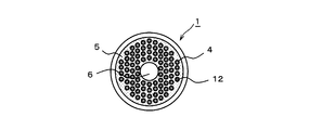
- FIG. 2 is a left side view of the hollow fiber membrane module 1 shown in FIG. 1
- FIG. 3 is a right side view of the hollow fiber membrane module 1 shown in FIG.
- the opening portion of the hollow fiber membrane 4 is a hollow opening portion 13 at the end of the hollow fiber membrane
- the opening portion of the hollow fiber membrane 4 is sealed with a sealing agent to form a hollow fiber.
- a membrane end hollow blocking portion 12 is provided, and a potting portion through hole 6 to the inside of the module is provided at the center portion of the potting portion 5 on the module end portion on the side where the hollow interior of the hollow fiber membrane is sealed. Yes.
- the hollow portion of the hollow fiber membrane is sealed with a sealant, there is no outflow or inflow of gas or liquid from the portion, and the potting portion through hole into the module provided in the central portion of the potting portion 5 6 functions as an outlet for the fluid supplied from the outside of the hollow fiber membrane bundle.
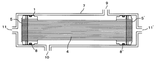
- FIG. 4 is a long axis showing a state in which the hollow fiber membrane module 1 shown in FIG. 1 is housed in the housing 7 through O-rings 8 and 8 ′ attached to the left bundled tube 2 or the right bundled tube 3. It is a direction center line end view.
- the conventional housing 7 was provided with the liquid outlet 10 in addition to the liquid inlet 9 on the side peripheral surface side with respect to the long axis direction of the hollow fiber membrane 4. Most of the liquids such as ethanol, isopropanol, and acetic acid only pass through the side peripheral surface of the hollow fiber membrane bundle or the vicinity thereof, but in the present invention, the liquid outlet 10 is on one end side of the hollow fiber membrane module 1.
- the liquid to be degassed reaches the hollow fiber membrane bundle central part from the outer surface of the hollow fiber membrane bundle, and all the contained liquids regardless of the arrangement position of the hollow fiber membrane 4 Since deaeration is performed by effectively using the hollow fiber membranes, it is possible to achieve further improvement in performance in the case of hollow fiber membrane modules using the same number of hollow fiber membranes.
Landscapes
- Chemical & Material Sciences (AREA)
- Chemical Kinetics & Catalysis (AREA)
- Engineering & Computer Science (AREA)
- Manufacturing & Machinery (AREA)
- Separation Using Semi-Permeable Membranes (AREA)
- Degasification And Air Bubble Elimination (AREA)
Abstract
中空糸膜両束端部をそれぞれ束着管に嵌挿し、中空糸膜の中空内部のみが外部に開放されるように中空糸膜両端部を各束着管にそれぞれポッティング部を介して固定せしめた中空糸膜モジュールにおいて、中空糸膜束の片端部の中空糸膜中空開口部を封止材によって封止せしめるとともに、中空糸膜の中空内部が封止された側のモジュール端部のポッティング部中央部分に、モジュール外部から供給された流体の流出口となる、モジュール内部への貫通穴を設けた中空糸膜モジュール。この中空糸膜モジュールは、中空糸膜束側周面あるいはその近傍に位置する中空糸膜のみならず、中空糸膜束内部に位置する多孔質中空糸膜をも有効に機能させることを可能とする。
Description
本発明は、中空糸膜モジュールに関する。さらに詳しくは、液体の脱気などに用いられる中空糸膜モジュールに関する。
現在、中空糸膜モジュールは液体の脱気、ろ過、分離、濃縮などに、あるいは気体の加湿、除湿などに用いられている。例えば、水中など液体中の気体を除去する方法としては、例えば特許文献1の図4に示されるような中空糸膜モジュールを用いた膜式脱気方法が採用されており、これは中空糸膜モジュールの中空糸膜束外側部に被処理液体を流し、中空糸膜内部空間側を減圧にしてそこから液体中に溶存する気体の除去が行われる。
このような中空糸膜モジュールとしては、例えば図5に示されるように、複数本の中空糸膜4の両束端部を左右の束着管にそれぞれ挿嵌し、各束着管に中空糸膜端部をポッティング部5、5’を介して固定せしめたものが用いられ、中空糸膜モジュール1の長軸方向に対して側周面からろ過の対象となる液体等が供給されるといったものが挙げられる。しかるに、これらの中空糸膜モジュール1をOリング8、8’を介して格納しているハウジング7には、液体流入口9および液体流出口10が中空糸膜4の長軸方向に対して側周面側に設けられている。その結果、膜モジュール側周面から供給された液体は、中空糸膜内部空間側を脱気口11、11’から減圧した場合に主として中空糸膜束の外表面を通過して脱気されることとなるため、中空糸膜束の中心部分に位置する中空糸膜4は、中空糸膜束外表面近傍に位置する中空糸膜4と比べると有効に使用されないものであった。
本発明の目的は、中空糸膜両束端部をそれぞれ束着管に嵌挿し、中空糸膜の中空内部のみが外部に開放されるように中空糸膜両端部を各束着管にポッティング部を介して固定せしめた中空糸膜モジュールにおいて、中空糸膜束側周面あるいはその近傍に位置する中空糸膜のみならず、中空糸膜束内部に位置する中空糸膜をも有効に機能させることを可能とする中空糸膜モジュールを提供することにある。
かかる本発明の目的は、中空糸膜両束端部をそれぞれ束着管に嵌挿し、中空糸膜の中空内部のみが外部に開放されるように中空糸膜両端部を各束着管にそれぞれポッティング部を介して固定せしめた中空糸膜モジュールにおいて、中空糸膜束の片端部の中空糸膜中空開口部を封止材によって封止せしめるとともに、中空糸膜の中空内部が封止された側のモジュール端部のポッティング部中央部分に、モジュール外部から供給された流体の流出口となる、モジュール内部への貫通穴を設けた中空糸膜モジュールによって達成される。
中空糸膜束の片端部の中空糸膜中空開口部を封止せめるとともに、中空糸膜、一般には多孔質中空糸膜の中空内部が封止されたモジュール端部のポッティング部中央部分にモジュール内部への貫通穴を設けることにより、中空糸膜モジュールに流体を循環させた場合、従来は主として中空糸膜束の側周面あるいはその近傍を通過していた流体、例えば液体が、中空糸膜束中心部を通過するようにその流路を変更することが可能となる。その結果、中空糸膜束の側周面付近だけではなく、中央部付近に位置する中空糸膜をも有効に機能させることができるといったすぐれた効果を奏する。
本発明に係る中空糸膜モジュールは、中空糸膜両束端部をそれぞれ束着管に嵌挿し、中空糸膜、一般には多孔質中空糸膜の中空内部のみが外部に開放されるように中空糸膜両端部を各束着管にそれぞれポッティング部を介して固定せしめた中空糸膜モジュールにおいて、中空糸膜束の片端部の中空糸膜中空開口部が封止材によって封止されるとともに、中空糸膜の中空内部が封止された側のモジュール端部のポッティング部中央部分に、モジュール外部から供給された流体の流出口となる、モジュール内部への貫通穴が設けられている。
多孔質中空糸膜としては、多孔質炭素製中空糸膜、多孔質セラミックス製中空糸膜などが挙げられ、多孔質炭素製中空糸膜としては、ポリフェニレンオキシド系、ポリイミド系、ポリスルホン系、セルロース系などの樹脂系材質のものを焼成したものが、また多孔質セラミックス製中空糸膜としては、Al2O3、Y2O3、MgO、SiO2、Si3N4、ZrO2製のものなどが用いられる。
以下、図面を参照しながら本発明に係る中空糸膜モジュール用の具体的態様を詳細に説明する。なお、以下に述べる具体的態様はあくまで本発明の一態様を例示しているに過ぎず、本発明は次の各態様に限定されるものではない。
図1は、本発明に係る中空糸膜モジュール1の一態様を示す一部端面正面図であり、図の上半分は中空糸膜モジュールの正面図、図の下半分は中空糸膜モジュールの長軸方向に対する中心線端面図となっている。左束着管2および右束着管3には、そこに充填される複数本の中空糸膜4、一般には多孔質中空糸膜からなる中空糸膜束端部がそれぞれ収容され、中空糸膜モジュールの両端部には、各中空糸膜4端部の外壁面間および中空糸膜4端部と左束着管2あるいは右束着管3との内壁面間を封止固定するポッティング部5、5’が備えられている。一般に、ポッティング部は、好ましくはエポキシ系接着剤のように耐熱性の高い接着剤で一次封入をして第1ポッティング部(外部側)を設け、さらに発熱の低い軟性のある接着剤で二次封入をして第2ポッティング部(内部側)を設けるといった多段ポッティングにより形成される。このように多段ポッティングとすることにより、ポッティングが硬化する際に生じる発熱を抑えることができ、特に中空糸膜との界面間の発熱を抑えることで中空糸膜の切れなどを防止することができる。
本発明においては、一方のポッティング部5に位置する中空糸膜4は、その中空内部がポッティング材と同じ材料によって封止されているが、他方のポッティング部5’に位置する中空糸膜4はその中空内部が外部に開放されている。中空内部が外部に開放されるように各中空糸膜端部の外壁面間および中空糸膜端部と右束着管3との内壁面間をそれぞれ封止固定してポッティング部を形成させる方法としては、例えばポッティングする前に中空糸膜端部の中空部を封止した後、ポッティングを行ってポッティング部形成し、さらに中空糸膜中空部が開口するように中空糸膜をカットする方法などが挙げられる。また、中空内部をポッティング材と同じ材料によって封止する方法としては、中空糸膜端部をポッティング材と同じ材料によって封止したうえで束着管内に収容し、ポッティング部を形成する態様のほか、中空糸膜端部を封止していない中空糸膜束を束着管内に収容し、ポッティング部を形成すると同時に中空糸膜端部の封止をあわせて行う方法が挙げられる。このとき、中空糸膜束の束着管内への収容は、中空糸膜端部を束着管端部と揃える態様のほか中空糸膜端部を束着管端部よりも束着管内側に配置して中空糸膜端部を封止する態様のいずれも用いることができる。
中空糸膜の中空内部が封止されたモジュール端部のポッティング部5の中央部分には、モジュール外部から供給された液体等の流体の流出口となる、モジュール内部へのポッティング部貫通穴6が設けられている。かかる貫通穴は、ポッティング前に例えば先端が円錐形となっている突起物を軸方向で中空糸膜束に挿入してポッティングを行った後、突起物を取り外すことなどによって形成される。
ポッティング部貫通穴6は、中空糸膜モジュール1の外部から供給された流体の流出口として機能する。脱気対象等となる流体は、中空糸膜束側周表面から供給されて中空糸膜束中央部まで到達した後、封止されたモジュール端部ポッティング部5の中央に設けられたポッティング部貫通穴6から流出することとなる。かかる構成を採用することにより、中空糸膜の配置位置にかかわらず収容されているすべての中空糸膜を有効に利用することができ、中空糸膜モジュールの性能を向上させることができるといったすぐれた効果を奏する。
図2は、図1で示した中空糸膜モジュール1の左側面図、図3は、図1で示した中空糸膜モジュール1の右側面図である。図3では中空糸膜4の開口部分は中空糸膜端部中空開口部13となっているのに対して、図2では中空糸膜4の開口部分が封止剤によって封止されて中空糸膜端部中空閉塞部12となっており、また中空糸膜の中空内部が封止された側のモジュール端部のポッティング部5の中央部分にモジュール内部へのポッティング部貫通穴6が設けられている。中空糸膜中空部分が封止剤によって封止されていることにより、かかる部分からの気体または液体の流出、流入はなく、ポッティング部5の中央部分に設けられたモジュール内部へのポッティング部貫通穴6が中空糸膜束外部より供給された流体の流出口となって機能することとなる。
図4は、図1で示した中空糸膜モジュール1を、左束着管2または右束着管3に装着したOリング8、8’を介してハウジング7に格納せしめた態様を示す長軸方向中心線端面図である。図5に示されるように、従来のハウジング7には中空糸膜4の長軸方向に対して側周面側に液体流入口9に加えて液体流出口10が設けられていたため、供給されたエタノール、イソプロパノール、酢酸などの液体の大部分は中空糸膜束の側周表面あるいはその近傍を通過するだけになっていたが、本発明では液体流出口10が中空糸膜モジュール1の片端部側に設けられることとなるため、脱気対象となる液体は、中空糸膜束外表面から中空糸膜束中央部まで到達することとなり、中空糸膜4の配置位置にかかわらず収容されたすべての中空糸膜を有効に利用して脱気が行われることから、同じ中空糸膜本数を用いた中空糸膜モジュールの場合に、さらなる性能の向上を達成せしめることが可能となる。
1 中空糸膜モジュール
2 左束着管
3 右束着管
4 中空糸膜
5、5’ ポッティング部
6 ポッティング部貫通穴
7 ハウジング
8、8’ Oリング
9 液体流入口
10 液体流出口
11、11’ 脱気口
12 中空糸膜端部中空閉塞部
13 中空糸膜端部中空開口部
2 左束着管
3 右束着管
4 中空糸膜
5、5’ ポッティング部
6 ポッティング部貫通穴
7 ハウジング
8、8’ Oリング
9 液体流入口
10 液体流出口
11、11’ 脱気口
12 中空糸膜端部中空閉塞部
13 中空糸膜端部中空開口部
Claims (4)
- 中空糸膜両束端部をそれぞれ束着管に嵌挿し、中空糸膜の中空内部のみが外部に開放されるように中空糸膜両端部を各束着管にそれぞれポッティング部を介して固定せしめた中空糸膜モジュールにおいて、
中空糸膜束の片端部の中空糸膜中空開口部を封止材によって封止せしめるとともに、中空糸膜の中空内部が封止された側のモジュール端部のポッティング部中央部分に、モジュール外部から供給された流体の流出口となる、モジュール内部への貫通穴を設けたことを特徴とする中空糸膜モジュール。 - 中空糸膜が多孔質中空糸膜である請求項1記載の中空糸膜モジュール。
- 中空糸膜の中空内部が、ポッティング材と同じ材料によって封止されている請求項1または2記載の中空糸膜モジュール。
- 液体の脱気に用いられる請求項1、2または3記載の中空糸膜モジュール。
Priority Applications (1)
| Application Number | Priority Date | Filing Date | Title |
|---|---|---|---|
| PCT/JP2014/052545 WO2015118607A1 (ja) | 2014-02-04 | 2014-02-04 | 中空糸膜モジュール |
Applications Claiming Priority (1)
| Application Number | Priority Date | Filing Date | Title |
|---|---|---|---|
| PCT/JP2014/052545 WO2015118607A1 (ja) | 2014-02-04 | 2014-02-04 | 中空糸膜モジュール |
Publications (1)
| Publication Number | Publication Date |
|---|---|
| WO2015118607A1 true WO2015118607A1 (ja) | 2015-08-13 |
Family
ID=53777448
Family Applications (1)
| Application Number | Title | Priority Date | Filing Date |
|---|---|---|---|
| PCT/JP2014/052545 Ceased WO2015118607A1 (ja) | 2014-02-04 | 2014-02-04 | 中空糸膜モジュール |
Country Status (1)
| Country | Link |
|---|---|
| WO (1) | WO2015118607A1 (ja) |
Citations (5)
| Publication number | Priority date | Publication date | Assignee | Title |
|---|---|---|---|---|
| JPH06327905A (ja) * | 1993-05-21 | 1994-11-29 | Toray Ind Inc | 脱気膜モジュールおよびその運転方法 |
| JP2000084369A (ja) * | 1998-09-10 | 2000-03-28 | Dainippon Ink & Chem Inc | 中空糸膜型気液ガス交換装置及びそのガス交換方法 |
| JP2002113334A (ja) * | 2000-10-05 | 2002-04-16 | Mitsubishi Rayon Co Ltd | 中空糸膜モジュール及び中空糸膜モジュールを用いた液体の処理方法 |
| JP2002282655A (ja) * | 2001-01-16 | 2002-10-02 | Toray Ind Inc | 中空糸膜モジュール |
| JP2008080262A (ja) * | 2006-09-28 | 2008-04-10 | Toray Ind Inc | 中空糸膜モジュールの製造方法 |
-
2014
- 2014-02-04 WO PCT/JP2014/052545 patent/WO2015118607A1/ja not_active Ceased
Patent Citations (5)
| Publication number | Priority date | Publication date | Assignee | Title |
|---|---|---|---|---|
| JPH06327905A (ja) * | 1993-05-21 | 1994-11-29 | Toray Ind Inc | 脱気膜モジュールおよびその運転方法 |
| JP2000084369A (ja) * | 1998-09-10 | 2000-03-28 | Dainippon Ink & Chem Inc | 中空糸膜型気液ガス交換装置及びそのガス交換方法 |
| JP2002113334A (ja) * | 2000-10-05 | 2002-04-16 | Mitsubishi Rayon Co Ltd | 中空糸膜モジュール及び中空糸膜モジュールを用いた液体の処理方法 |
| JP2002282655A (ja) * | 2001-01-16 | 2002-10-02 | Toray Ind Inc | 中空糸膜モジュール |
| JP2008080262A (ja) * | 2006-09-28 | 2008-04-10 | Toray Ind Inc | 中空糸膜モジュールの製造方法 |
Similar Documents
| Publication | Publication Date | Title |
|---|---|---|
| JP5543875B2 (ja) | 中空糸モジュール | |
| KR102432606B1 (ko) | 제습 엘리먼트 및 그것을 갖는 제습 장치 | |
| EP4458444A1 (en) | Degassing module and method for degassing liquid | |
| JP6615969B1 (ja) | 中空糸膜モジュール | |
| US10729991B2 (en) | Compact cross-flow contactor | |
| KR101707969B1 (ko) | 가압식 중공사막 모듈 | |
| JP5708619B2 (ja) | 中空糸膜モジュール | |
| WO2015118607A1 (ja) | 中空糸膜モジュール | |
| WO2018092342A1 (ja) | 濾過モジュール及び濾過装置 | |
| CN104144885B (zh) | 内窥镜清洗装置用过滤装置 | |
| JP6439560B2 (ja) | 中空糸膜カートリッジ | |
| EP3434348B1 (en) | Fluid degassing devices having selected profiles | |
| JP6973074B2 (ja) | 分離膜モジュール | |
| CN108404675B (zh) | 内压式中空纤维膜组件 | |
| JP4362432B2 (ja) | 中空糸型モジュール | |
| JP6209474B2 (ja) | 中空糸膜モジュール | |
| KR101672506B1 (ko) | 중공사막 모듈 | |
| KR20180033902A (ko) | 중공사형 막 모듈 | |
| JP6277666B2 (ja) | 浄水カートリッジ | |
| JP2016036755A (ja) | 多孔質セラミックス中空糸膜モジュール | |
| JP4183589B2 (ja) | 中空糸膜型体液処理器 | |
| JP5825008B2 (ja) | ガス分離膜モジュール | |
| WO2022153903A1 (ja) | ベント構造を有するフィルタ容器システム | |
| JP2008119590A (ja) | 中空糸膜フィルターカートリッジおよびその製造方法 | |
| JP2005342394A (ja) | 中空糸型モジュール |
Legal Events
| Date | Code | Title | Description |
|---|---|---|---|
| 121 | Ep: the epo has been informed by wipo that ep was designated in this application |
Ref document number: 14881478 Country of ref document: EP Kind code of ref document: A1 |
|
| NENP | Non-entry into the national phase |
Ref country code: DE |
|
| 122 | Ep: pct application non-entry in european phase |
Ref document number: 14881478 Country of ref document: EP Kind code of ref document: A1 |
|
| NENP | Non-entry into the national phase |
Ref country code: JP |