WO2015115305A1 - 排ガス処理装置 - Google Patents
排ガス処理装置 Download PDFInfo
- Publication number
- WO2015115305A1 WO2015115305A1 PCT/JP2015/051726 JP2015051726W WO2015115305A1 WO 2015115305 A1 WO2015115305 A1 WO 2015115305A1 JP 2015051726 W JP2015051726 W JP 2015051726W WO 2015115305 A1 WO2015115305 A1 WO 2015115305A1
- Authority
- WO
- WIPO (PCT)
- Prior art keywords
- exhaust gas
- gas
- flue
- dust collector
- supplying
- Prior art date
- Legal status (The legal status is an assumption and is not a legal conclusion. Google has not performed a legal analysis and makes no representation as to the accuracy of the status listed.)
- Ceased
Links
Images

Classifications
-
- B—PERFORMING OPERATIONS; TRANSPORTING
- B01—PHYSICAL OR CHEMICAL PROCESSES OR APPARATUS IN GENERAL
- B01D—SEPARATION
- B01D53/00—Separation of gases or vapours; Recovering vapours of volatile solvents from gases; Chemical or biological purification of waste gases, e.g. engine exhaust gases, smoke, fumes, flue gases, aerosols
- B01D53/34—Chemical or biological purification of waste gases
- B01D53/46—Removing components of defined structure
- B01D53/48—Sulfur compounds
- B01D53/50—Sulfur oxides
-
- F—MECHANICAL ENGINEERING; LIGHTING; HEATING; WEAPONS; BLASTING
- F23—COMBUSTION APPARATUS; COMBUSTION PROCESSES
- F23J—REMOVAL OR TREATMENT OF COMBUSTION PRODUCTS OR COMBUSTION RESIDUES; FLUES
- F23J15/00—Arrangements of devices for treating smoke or fumes
- F23J15/003—Arrangements of devices for treating smoke or fumes for supplying chemicals to fumes, e.g. using injection devices
-
- B—PERFORMING OPERATIONS; TRANSPORTING
- B01—PHYSICAL OR CHEMICAL PROCESSES OR APPARATUS IN GENERAL
- B01D—SEPARATION
- B01D53/00—Separation of gases or vapours; Recovering vapours of volatile solvents from gases; Chemical or biological purification of waste gases, e.g. engine exhaust gases, smoke, fumes, flue gases, aerosols
- B01D53/34—Chemical or biological purification of waste gases
- B01D53/46—Removing components of defined structure
- B01D53/48—Sulfur compounds
- B01D53/50—Sulfur oxides
- B01D53/501—Sulfur oxides by treating the gases with a solution or a suspension of an alkali or earth-alkali or ammonium compound
-
- B—PERFORMING OPERATIONS; TRANSPORTING
- B01—PHYSICAL OR CHEMICAL PROCESSES OR APPARATUS IN GENERAL
- B01D—SEPARATION
- B01D53/00—Separation of gases or vapours; Recovering vapours of volatile solvents from gases; Chemical or biological purification of waste gases, e.g. engine exhaust gases, smoke, fumes, flue gases, aerosols
- B01D53/34—Chemical or biological purification of waste gases
- B01D53/46—Removing components of defined structure
- B01D53/54—Nitrogen compounds
- B01D53/56—Nitrogen oxides
-
- B—PERFORMING OPERATIONS; TRANSPORTING
- B01—PHYSICAL OR CHEMICAL PROCESSES OR APPARATUS IN GENERAL
- B01D—SEPARATION
- B01D53/00—Separation of gases or vapours; Recovering vapours of volatile solvents from gases; Chemical or biological purification of waste gases, e.g. engine exhaust gases, smoke, fumes, flue gases, aerosols
- B01D53/34—Chemical or biological purification of waste gases
- B01D53/46—Removing components of defined structure
- B01D53/64—Heavy metals or compounds thereof, e.g. mercury
-
- B—PERFORMING OPERATIONS; TRANSPORTING
- B01—PHYSICAL OR CHEMICAL PROCESSES OR APPARATUS IN GENERAL
- B01D—SEPARATION
- B01D53/00—Separation of gases or vapours; Recovering vapours of volatile solvents from gases; Chemical or biological purification of waste gases, e.g. engine exhaust gases, smoke, fumes, flue gases, aerosols
- B01D53/34—Chemical or biological purification of waste gases
- B01D53/74—General processes for purification of waste gases; Apparatus or devices specially adapted therefor
- B01D53/75—Multi-step processes
-
- F—MECHANICAL ENGINEERING; LIGHTING; HEATING; WEAPONS; BLASTING
- F23—COMBUSTION APPARATUS; COMBUSTION PROCESSES
- F23J—REMOVAL OR TREATMENT OF COMBUSTION PRODUCTS OR COMBUSTION RESIDUES; FLUES
- F23J15/00—Arrangements of devices for treating smoke or fumes
- F23J15/02—Arrangements of devices for treating smoke or fumes of purifiers, e.g. for removing noxious material
- F23J15/04—Arrangements of devices for treating smoke or fumes of purifiers, e.g. for removing noxious material using washing fluids
-
- F—MECHANICAL ENGINEERING; LIGHTING; HEATING; WEAPONS; BLASTING
- F23—COMBUSTION APPARATUS; COMBUSTION PROCESSES
- F23J—REMOVAL OR TREATMENT OF COMBUSTION PRODUCTS OR COMBUSTION RESIDUES; FLUES
- F23J15/00—Arrangements of devices for treating smoke or fumes
- F23J15/06—Arrangements of devices for treating smoke or fumes of coolers
-
- F—MECHANICAL ENGINEERING; LIGHTING; HEATING; WEAPONS; BLASTING
- F23—COMBUSTION APPARATUS; COMBUSTION PROCESSES
- F23L—SUPPLYING AIR OR NON-COMBUSTIBLE LIQUIDS OR GASES TO COMBUSTION APPARATUS IN GENERAL ; VALVES OR DAMPERS SPECIALLY ADAPTED FOR CONTROLLING AIR SUPPLY OR DRAUGHT IN COMBUSTION APPARATUS; INDUCING DRAUGHT IN COMBUSTION APPARATUS; TOPS FOR CHIMNEYS OR VENTILATING SHAFTS; TERMINALS FOR FLUES
- F23L15/00—Heating of air supplied for combustion
- F23L15/04—Arrangements of recuperators
-
- B—PERFORMING OPERATIONS; TRANSPORTING
- B01—PHYSICAL OR CHEMICAL PROCESSES OR APPARATUS IN GENERAL
- B01D—SEPARATION
- B01D2251/00—Reactants
- B01D2251/40—Alkaline earth metal or magnesium compounds
- B01D2251/404—Alkaline earth metal or magnesium compounds of calcium
-
- B—PERFORMING OPERATIONS; TRANSPORTING
- B01—PHYSICAL OR CHEMICAL PROCESSES OR APPARATUS IN GENERAL
- B01D—SEPARATION
- B01D2251/00—Reactants
- B01D2251/60—Inorganic bases or salts
- B01D2251/602—Oxides
-
- B—PERFORMING OPERATIONS; TRANSPORTING
- B01—PHYSICAL OR CHEMICAL PROCESSES OR APPARATUS IN GENERAL
- B01D—SEPARATION
- B01D2251/00—Reactants
- B01D2251/60—Inorganic bases or salts
- B01D2251/604—Hydroxides
-
- B—PERFORMING OPERATIONS; TRANSPORTING
- B01—PHYSICAL OR CHEMICAL PROCESSES OR APPARATUS IN GENERAL
- B01D—SEPARATION
- B01D2251/00—Reactants
- B01D2251/60—Inorganic bases or salts
- B01D2251/606—Carbonates
-
- B—PERFORMING OPERATIONS; TRANSPORTING
- B01—PHYSICAL OR CHEMICAL PROCESSES OR APPARATUS IN GENERAL
- B01D—SEPARATION
- B01D2257/00—Components to be removed
- B01D2257/30—Sulfur compounds
- B01D2257/302—Sulfur oxides
-
- B—PERFORMING OPERATIONS; TRANSPORTING
- B01—PHYSICAL OR CHEMICAL PROCESSES OR APPARATUS IN GENERAL
- B01D—SEPARATION
- B01D2257/00—Components to be removed
- B01D2257/40—Nitrogen compounds
- B01D2257/404—Nitrogen oxides other than dinitrogen oxide
-
- B—PERFORMING OPERATIONS; TRANSPORTING
- B01—PHYSICAL OR CHEMICAL PROCESSES OR APPARATUS IN GENERAL
- B01D—SEPARATION
- B01D53/00—Separation of gases or vapours; Recovering vapours of volatile solvents from gases; Chemical or biological purification of waste gases, e.g. engine exhaust gases, smoke, fumes, flue gases, aerosols
- B01D53/34—Chemical or biological purification of waste gases
- B01D53/74—General processes for purification of waste gases; Apparatus or devices specially adapted therefor
- B01D53/86—Catalytic processes
- B01D53/869—Multiple step processes
-
- F—MECHANICAL ENGINEERING; LIGHTING; HEATING; WEAPONS; BLASTING
- F23—COMBUSTION APPARATUS; COMBUSTION PROCESSES
- F23J—REMOVAL OR TREATMENT OF COMBUSTION PRODUCTS OR COMBUSTION RESIDUES; FLUES
- F23J2215/00—Preventing emissions
- F23J2215/10—Nitrogen; Compounds thereof
-
- F—MECHANICAL ENGINEERING; LIGHTING; HEATING; WEAPONS; BLASTING
- F23—COMBUSTION APPARATUS; COMBUSTION PROCESSES
- F23J—REMOVAL OR TREATMENT OF COMBUSTION PRODUCTS OR COMBUSTION RESIDUES; FLUES
- F23J2215/00—Preventing emissions
- F23J2215/20—Sulfur; Compounds thereof
-
- F—MECHANICAL ENGINEERING; LIGHTING; HEATING; WEAPONS; BLASTING
- F23—COMBUSTION APPARATUS; COMBUSTION PROCESSES
- F23J—REMOVAL OR TREATMENT OF COMBUSTION PRODUCTS OR COMBUSTION RESIDUES; FLUES
- F23J2219/00—Treatment devices
- F23J2219/10—Catalytic reduction devices
-
- F—MECHANICAL ENGINEERING; LIGHTING; HEATING; WEAPONS; BLASTING
- F23—COMBUSTION APPARATUS; COMBUSTION PROCESSES
- F23J—REMOVAL OR TREATMENT OF COMBUSTION PRODUCTS OR COMBUSTION RESIDUES; FLUES
- F23J2219/00—Treatment devices
- F23J2219/60—Sorption with dry devices, e.g. beds
-
- Y—GENERAL TAGGING OF NEW TECHNOLOGICAL DEVELOPMENTS; GENERAL TAGGING OF CROSS-SECTIONAL TECHNOLOGIES SPANNING OVER SEVERAL SECTIONS OF THE IPC; TECHNICAL SUBJECTS COVERED BY FORMER USPC CROSS-REFERENCE ART COLLECTIONS [XRACs] AND DIGESTS
- Y02—TECHNOLOGIES OR APPLICATIONS FOR MITIGATION OR ADAPTATION AGAINST CLIMATE CHANGE
- Y02A—TECHNOLOGIES FOR ADAPTATION TO CLIMATE CHANGE
- Y02A50/00—TECHNOLOGIES FOR ADAPTATION TO CLIMATE CHANGE in human health protection, e.g. against extreme weather
- Y02A50/20—Air quality improvement or preservation, e.g. vehicle emission control or emission reduction by using catalytic converters
-
- Y—GENERAL TAGGING OF NEW TECHNOLOGICAL DEVELOPMENTS; GENERAL TAGGING OF CROSS-SECTIONAL TECHNOLOGIES SPANNING OVER SEVERAL SECTIONS OF THE IPC; TECHNICAL SUBJECTS COVERED BY FORMER USPC CROSS-REFERENCE ART COLLECTIONS [XRACs] AND DIGESTS
- Y02—TECHNOLOGIES OR APPLICATIONS FOR MITIGATION OR ADAPTATION AGAINST CLIMATE CHANGE
- Y02E—REDUCTION OF GREENHOUSE GAS [GHG] EMISSIONS, RELATED TO ENERGY GENERATION, TRANSMISSION OR DISTRIBUTION
- Y02E20/00—Combustion technologies with mitigation potential
- Y02E20/34—Indirect CO2mitigation, i.e. by acting on non CO2directly related matters of the process, e.g. pre-heating or heat recovery
Definitions
- the present invention relates to an exhaust gas treatment apparatus that can follow fluctuations in SO 3 concentration in exhaust gas.
- SO x sulfur oxides
- SO 2 sulfur dioxide
- SO 3 sulfur trioxide
- the sulfur (S) content derived from the fuel of a thermal power plant is oxidized by the catalyst component in the fuel or the catalyst of the denitration device, and from sulfur dioxide (SO 2 ) to sulfur trioxide (SO 3 ) component Convert to
- the converted SO 3 concentration may reach a maximum of about 30 to 50 ppm in the exhaust gas from coal-fired boilers, and may reach a maximum of around 180 ppm for oil-fired and heavy fuels, depending on the boiler fouling condition and combustion conditions.
- the SO 3 in the exhaust gas causes troubles such as equipment corrosion and blockage due to increased ash adhesion in the low-temperature equipment downstream of the air heater, and increases maintenance costs for power plant users.
- SO 3 is known as a typical causative component of purple smoke from the chimney, and the plant may be forced to stop when the purple smoke is dark.
- SO 3 is the fuel property, contamination of the boiler furnace, although over time the concentration by the active state of the denitration catalyst varies from that on-line measurements of SO 3 concentration was difficult, the conventional CaCO 3
- the SO 3 concentration at the time of trial operation was measured by a chemical analysis method, or it was often sprayed excessively with respect to this SO 3 concentration assuming the maximum SO 3 concentration. For this reason, when the plant operating conditions fluctuate and increase to an unexpected SO 3 concentration, there is a problem that the chemical becomes insufficient, the SO 3 removal performance decreases, and pressure loss increase due to ash adhesion and corrosion is promoted. .
- the SO 3 concentration is lower than expected, it is also a factor in injecting an excessive amount of chemicals and introducing wasteful costs.
- an object of the present invention is to provide an exhaust gas treatment apparatus that can adjust the supply amount of the SO 3 removal agent and follow the variation in the SO 3 concentration in the exhaust gas.
- a first invention of the present invention for solving the above-described problems includes a denitration device for removing nitrogen oxides in exhaust gas from a boiler, an air preheater for recovering heat in the exhaust gas after removing nitrogen oxides, A dust collector that removes soot and dust in the exhaust gas after heat recovery, a gas-liquid contact type desulfurization device that removes sulfur oxide in the exhaust gas after dust removal, a chimney that discharges the exhaust gas after desulfurization to the outside, and SO 3 removing agent supply device for supplying the exhaust gas flue of SO 3 removal agent into the exhaust gas at the feed section of the upstream side of the dust collector, in the downstream side of the air preheater, the SO 3 removal agent
- the exhaust gas treatment apparatus includes a wet state treatment unit that supplies moisture to a part of the exhaust gas to make it wet in the exhaust gas flue on the upstream side of the supply unit that supplies the exhaust gas flue.
- the wet state processing unit rises in a direction orthogonal to the flue gas flue for discharging the exhaust gas, a gas ascending passage and a gas in the riser
- An exhaust gas treatment apparatus comprising: a partition section that partitions into a descending passage; and a droplet supply section that supplies droplets in the gas descending passage partitioned by the partition section.
- the third invention is the exhaust gas treatment apparatus according to the first or second invention, wherein a hopper is provided below the rising portion.
- a fourth invention is the exhaust gas treatment apparatus according to any one of the first to third inventions, wherein the desulfurization waste water or the dehydrated filtrate from the desulfurization apparatus is supplied to the wet state treatment unit.
- the exhaust gas treatment apparatus further comprises an Hg removal agent supply means for supplying an Hg removal agent into the exhaust gas on the front side of the dust collector. is there.
- the sixth invention in any one invention of the first to fifth, a part of the fly ash containing SO 3 removing agent recovered by the dust collector, the dust collector of the front SO 3 removal agent
- the exhaust gas treatment apparatus is provided with a return line for supplying the exhaust gas in the vicinity of the exhaust gas.
- a seventh aspect of the invention is the exhaust gas treatment apparatus according to any one of the first to sixth aspects, further comprising a gas gas heater between the supply unit that supplies the SO 3 removing agent and the dust collector. It is in.
- the eighth invention is a denitration device that removes nitrogen oxides in exhaust gas from a boiler, an air preheater that recovers heat in the exhaust gas after removing nitrogen oxides, and heat exchange of the heat of the exhaust gas after heat recovery Gas gas heater, dust collector that removes dust in exhaust gas after heat recovery, gas-liquid contact type desulfurization device that removes sulfur oxide in exhaust gas after dust removal, and exhaust gas after desulfurization to the outside A chimney, an SO 3 removal agent supply device for supplying an SO 3 removal agent into the exhaust gas in the exhaust gas at a supply portion on the downstream side of the air preheater and the upstream side of the gas gas heater, and the gas
- An exhaust gas treatment comprising: a wet state treatment unit which supplies moisture to a part of the exhaust gas in a flue gas flue on the downstream side of the gas heater and on the upstream side of the dust collector. In the device.
- the wet state treatment unit rises in a direction orthogonal to the flue gas flue from which the exhaust gas is discharged, a gas ascending passage and a gas in the riser
- An exhaust gas treatment apparatus comprising: a partition section that partitions into a descending passage; and a droplet supply section that supplies droplets in the gas descending passage partitioned by the partition section.
- a tenth aspect of the invention is an exhaust gas treatment apparatus according to the eighth or ninth aspect of the invention, further comprising a hopper below the rising portion.
- An eleventh aspect of the invention is an exhaust gas treatment apparatus according to any one of the eighth to tenth aspects of the invention, wherein desulfurization waste water or dehydrated filtrate from the desulfurization apparatus is supplied to the wet state treatment unit.
- a twelfth aspect of the present invention is the exhaust gas treatment apparatus according to any one of the eighth to eleventh aspects, further comprising an Hg removal agent supply means for supplying an Hg removal agent into the exhaust gas on the front side of the dust collector. is there.
- a thirteenth invention in any one invention of the eighth to 12, a part of the fly ash containing SO 3 removing agent recovered by the dust collector, the dust collector of the front SO 3 removal agent
- the exhaust gas treatment apparatus is provided with a return line for supplying the exhaust gas in the vicinity of the exhaust gas.
- moisture is actively supplied by supplying moisture to the exhaust gas, so that water is present at the interface near the powder surface of the supplied SO 3 removing agent.
- a chemical reaction in which SO 3 in the exhaust gas is absorbed on the surface of the SO 3 removing agent powder can be actively promoted.
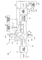
- FIG. 1 is a schematic diagram of an exhaust gas treatment apparatus according to a first embodiment.
- FIG. 2 is a schematic view of the calcium carbonate in a wet state.
- FIG. 3 is a schematic view of an exhaust gas flue according to the second embodiment.
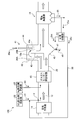
- FIG. 4 is a schematic flowchart of the exhaust gas processing apparatus according to the second embodiment.
- FIG. 5 is a schematic flowchart of the exhaust gas treatment apparatus according to the third embodiment.
- FIG. 6 is a schematic flowchart of the exhaust gas treatment apparatus according to the fourth embodiment.
- FIG. 7 is a schematic flowchart of the exhaust gas treatment apparatus according to the fifth embodiment.
- FIG. 1 is a schematic diagram of an exhaust gas treatment apparatus according to a first embodiment.
- the exhaust gas treatment apparatus 10A recovers heat in the exhaust gas 12 after removing the nitrogen oxide in the exhaust gas 12 from the boiler 11 and the nitrogen oxide removed.
- the SO 3 removal agent 31 is supplied into the exhaust gas flue in the exhaust gas 12 by the contact-type desulfurization device 16, the chimney 17 that discharges the exhaust gas after desulfurization to the outside, and the supply section X on the upstream side of the dust collector 15.
- a wet state processing unit 41 for supplying moisture to a part of the water Is shall.
- symbol F is fuel supplied to the boiler
- A is air
- 25 is dust collection ash from the dust collector
- 26 is desulfurization drainage
- 27 is a belt filter that separates the gypsum 28 from the desulfurization drainage
- 29 is The dehydrated filtrate from which the gypsum 28 has been separated by the belt filter 27 is illustrated.
- a part 29a of the dehydrated filtrate 29 is used in the exhaust gas 12 as water supplied from the outside.
- the exhaust gas flue 20 is provided with the wet state treatment unit 41 that partially wets the exhaust gas, the amount of water finely sprayed on the exhaust gas 12 increases and the gas temperature also decreases.
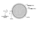
- FIG. 2 is a schematic view of the calcium carbonate in a wet state.
- the gas temperature of the exhaust gas 12 is after passing through the air preheater 14, when the gas temperature of the exhaust gas 12 after passing through the denitration device 13 is 350 ° C., for example, it becomes about 180 ° C., for example.
- the outer surface gas film 52 of the wet CaCO 3 water film film 51 covered with the water film film film 51 is about 180 ° C., which is the same as the gas temperature. In 51, it becomes about 70 degreeC (wet bulb temperature of water), and a big temperature gradient arises in both boundary films by this temperature difference. Due to this temperature gradient, the exhaust gas 12 containing gaseous SO 3 entering the calcium carbonate becomes lower than the acid dew point temperature (140 to 150 ° C.).
- the portion 29a of the dehydrated filtrate 29 is supplied to the exhaust gas 12 so as to be actively moistened.
- a temperature gradient involving water is generated, and a chemical reaction in which SO 3 in the exhaust gas 12 becomes calcium sulfate is actively performed on the surface of calcium carbonate.
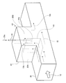
- FIG. 3 is a conceptual diagram of an exhaust gas flue according to the second embodiment.
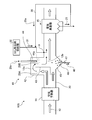
- FIG. 4 is a schematic flowchart of the exhaust gas processing apparatus according to the second embodiment.
- symbol is attached
- FIG. 4 shows only the main part of the exhaust gas treatment apparatus shown in FIG. 1, and others are omitted (the same applies to the following examples). As shown in FIGS.
- the exhaust gas treatment apparatus 10 ⁇ / b> B of the present embodiment, as the wet state treatment unit 41, a startup unit 42 that rises in a direction perpendicular to the exhaust gas flue 20 that exhausts the exhaust gas 12 from the boiler 11.
- the rising portion 42 is divided into a gas rising passage 20A and a gas lowering passage 20B, an inverted L-shaped partitioning portion 43, and a gas dropping passage 20B partitioned by the partitioning portion 43 into a droplet 44a.
- a part 25a of the dust collection ash 25 containing the unreacted SO 3 removal agent 31 collected by the dust collectors 15 in the three sections 15-1 to 15-3 is disposed on the front side of the dust collector 15.
- a return line 35 for supplying the SO 3 removing agent 31 in the vicinity of the exhaust gas 12 is provided to join the SO 3 removing agent 31 supplied from the SO 3 removing agent supply unit 32 and sprayed into the exhaust flue 20.
- the supply of the part 25a of the dust collection ash 25 is merged with the SO 3 removal agent 31 and sprayed into the flue gas flue 20, but the part 25a of the dust collection ash 25 is separated. You may make it spray in the exhaust gas flue 20 separately separately in a line.
- the droplet supply unit 44 sprays fine droplets using a spray nozzle or the like that sprays the dehydrated filtrate 29a.
- a spray nozzle it is considered that a two-fluid nozzle capable of miniaturizing droplets can be applied.
- the present invention is not limited to this.
- the wet exhaust gas 12b merges with the exhaust gas 12 that has passed through the lower side of the partition portion 43.
- a hopper 45 is provided on the bottom surface side of the flue gas flue 20 of the start-up portion 42, and when the droplets 44a are sprayed or when the solid matter 46 adhering to the vicinity of the nozzle falls, it enters the flue. Prevents accumulation.
- a rotary valve 47 is provided at the bottom of the hopper 45 so that the solid matter 46 is periodically removed.
- Ca ions, SO 4 ions, Cl ions, etc. in the dehydrated filtrate 29a are evaporated to form a salt form, or a part of the reaction gypsum / unreacted calcium carbonate or accompanying substances. And a mixture of combustion ash.
- droplets when droplets are sprayed, they are sprayed in the gas descending passage 20B of the rising portion 42 and sprayed in the same direction as the gas flow direction (left and right direction in the figure) in the exhaust gas flue 20. Not done.
- coarse solids 46 adhering to and dropping out from the nozzle periphery and surrounding structures may accumulate in the flue and obstruct the droplet spraying operation.
- the droplets 44a are sprayed along the descending flow of the rising portion.
- the solid matter 46 adhering to the periphery of the nozzle may obstruct the miniaturization of the droplets, it may be removed by intermittent beating or removal air by installing a removal device.
- the dehydrated filtrate 29a is used as water for supplying droplets, but the present invention is not limited to this.
- a part of the desulfurization waste water 26 before separating the gypsum 28 may be used.
- the gypsum slurry concentration may be adjusted using water.
- a part of the dust collection ash 25 collected by the electric dust collector 15 is returned again into the flue through the dust collection ash supply line.
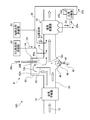
- FIG. 5 is a schematic flowchart of the exhaust gas treatment apparatus according to the third embodiment.
- the exhaust gas treatment apparatus 10 ⁇ / b> C according to the present embodiment further includes an Hg removal agent supply unit 62 that supplies an Hg removal agent 61 into the exhaust gas on the front side of the dust collector 15 in the second embodiment. SO 3 in the exhaust gas is removed and mercury in the exhaust gas is removed.
- the Hg removing agent is supplied on the upstream side of the dust collector 15 and on the downstream side of the supply unit X that supplies the SO 3 removing agent 31 into the exhaust gas flue 20.
- activated carbon (AC) can be exemplified.
- the SO 3 concentration in the exhaust gas 12 is reduced, so that the amount of activated carbon necessary for mercury-removing activated carbon (AC) is reduced, and the activated carbon necessary for Hg removal is reduced.
- the amount of addition can be minimized.
- the return line 35 for supplying the separated product 25c of the SO 3 remover 31 and the Hg remover 61 into the exhaust gas 12 is provided.
- the SO 3 remover 31 and the Hg remover are provided in the return line.
- a specific gravity separator 63 that separates a portion 25 a of the dust collection ash 25 including the agent 61 into fly ash 25 b and a separated product 25 c of the SO 3 removal agent 31 and the Hg removal agent 61 is provided. Then, the separated product 25c of the SO 3 removing agent 31 and the Hg removing agent 61 excluding the fly ash 25b separated by specific gravity is supplied into the exhaust gas 12. This makes it possible to reuse only the SO 3 removal agent 31 and Hg-removing agent 61 unreacted during SO 3 removal and Hg removal.
- FIG. 6 is a schematic flowchart of the exhaust gas treatment apparatus according to the fourth embodiment.
- symbol is attached
- a gas gas heater (GGH) heat recovery device 65 is further provided on the front side of the dust collector 15 to recover the heat of the exhaust gas 12.
- the heat medium after heat recovery is supplied for low-pressure turbine side feed water heating, and the cooled heat medium is returned to the gas gas heater (GGH) heat recovery device 65 and circulated ( The circulation line is omitted).
- GGH gas gas heater
- the exhaust gas temperature is further lowered. Therefore, the condensed SO 3 mist in the exhaust gas 12 after passing through the gas gas heater (GGH) heat recovery unit 65 is It is made to react with the unreacted calcium carbonate (CaCO 3 ) that is entrained in the catalyst to further improve the SO 3 removal efficiency.
- CaCO 3 unreacted calcium carbonate
- FIG. 7 is a schematic flowchart of the exhaust gas treatment apparatus according to the fifth embodiment.
- symbol is attached
- the exhaust gas treatment device 10E of this embodiment includes a denitration device 13 that removes nitrogen oxides in the exhaust gas 12 from the boiler, and air that recovers heat in the exhaust gas 12 after the removal of nitrogen oxides.
- the upstream side supply unit Y is the downstream side of the SO 3 removal agent supply unit 32 for supplying the SO 3 removal agent 31 into the exhaust gas flue 20 and the gas gas heater (GGH) heat recovery unit 65 in the upstream side.
- a wet state processing unit 41 for making a part of the exhaust gas 12 into a wet state.
- the wet state processing unit 41 is installed on the downstream side of the gas gas heater (GGH) heat recovery unit 65, so that the gas temperature of the exhaust gas 12 after passing through the gas gas heater (GGH) heat recovery unit 65 is 100 ° C.
- the gas temperature of the exhaust gas 12 after passing through the gas gas heater (GGH) heat recovery unit 65 is 100 ° C.
- SO 3 remaining in the exhaust gas after passing through the gas gas heater (GGH) heat recovery device 65 is reacted with unreacted calcium carbonate, Further, the SO 3 removal efficiency is improved.
Landscapes
- Engineering & Computer Science (AREA)
- Chemical & Material Sciences (AREA)
- Environmental & Geological Engineering (AREA)
- Chemical Kinetics & Catalysis (AREA)
- General Chemical & Material Sciences (AREA)
- Mechanical Engineering (AREA)
- General Engineering & Computer Science (AREA)
- Health & Medical Sciences (AREA)
- Biomedical Technology (AREA)
- Analytical Chemistry (AREA)
- Oil, Petroleum & Natural Gas (AREA)
- Combustion & Propulsion (AREA)
- Treating Waste Gases (AREA)
- Chimneys And Flues (AREA)
- Exhaust Gas Treatment By Means Of Catalyst (AREA)
Abstract
ボイラ11からの排ガス12中の窒素酸化物を除去する脱硝装置13と、窒素酸化物除去後の排ガス12中の熱を回収する空気予熱器14と、熱回収後の排ガス12中の煤塵を除去する電気集塵器15と、除塵後の排ガス12中の硫黄酸化物を除去する気液接触式の脱硫装置16と、脱硫後の排ガスを外部に排出する煙突17と、集塵器15の前流側の供給部Xで排ガス12中にSO3除去剤31を排ガス煙道内に供給するSO3除去剤供給部32と、空気予熱器14の後流側で、SO3除去剤31を排ガス煙道20内に供給する供給部Xの前流側の排ガス煙道20内において、排ガス12の一部を湿潤状態とする湿潤状態処理部41とを備える。
Description
本発明は、排ガス中のSO3濃度の変動に追従することができる排ガス処理装置に関するものである。
例えば、発電所等のボイラから排出される排ガスに含まれる硫黄酸化物(SOx)の大部分は二酸化硫黄(SO2)であるが、一部は共存する燃焼灰や脱硝触媒に担持された酸化金属の触媒作用などで三酸化硫黄(SO3)に転化する。SO3は反応性と腐食性とが高いことから、従来は設備劣化の防止のためにアンモニアの煙道注入による中和処理が一般になされている。
火力発電所の燃料由来の硫黄(S)分はボイラで燃焼する際に、同燃料中の触媒成分や脱硝装置の触媒で酸化し、二酸化硫黄(SO2)から三酸化硫黄(SO3)成分に転換する。この転換したSO3濃度は、石炭焚きボイラの排ガス中では最大30~50ppm程度、油焚き・重質燃料ではボイラの火炉汚れ状態や燃焼条件にもよるが最大180ppm前後にまで達する事もある。
排ガス中のSO3は、エアヒータ後流の低温設備にて例えば機器腐食や灰付着性増大による閉塞等のトラブルの原因となり、発電プラントユーザのメンテナンスコストを増大させる要因となる。
また、SO3は煙突からの紫煙の代表的な原因成分として知られており、紫煙が濃い場合にはプラント停止を余儀なくされる事がある。
火力発電所の燃料由来の硫黄(S)分はボイラで燃焼する際に、同燃料中の触媒成分や脱硝装置の触媒で酸化し、二酸化硫黄(SO2)から三酸化硫黄(SO3)成分に転換する。この転換したSO3濃度は、石炭焚きボイラの排ガス中では最大30~50ppm程度、油焚き・重質燃料ではボイラの火炉汚れ状態や燃焼条件にもよるが最大180ppm前後にまで達する事もある。
排ガス中のSO3は、エアヒータ後流の低温設備にて例えば機器腐食や灰付着性増大による閉塞等のトラブルの原因となり、発電プラントユーザのメンテナンスコストを増大させる要因となる。
また、SO3は煙突からの紫煙の代表的な原因成分として知られており、紫煙が濃い場合にはプラント停止を余儀なくされる事がある。
そこで、従来においては、このSO3の除去対策として、例えば煙道中に、アンモニアを導入する以外にCaCO3やCa(OH)2、CaO等を噴霧したり、活性炭(AC(Active Carbon);炭素を主成分とする多孔性の不純物吸着材)を噴霧したりしてSOxを除去する提案がある(特許文献1及び2)。
また、さらに煙道中において、電気集塵器の前流側に熱回収器としてガスガスヒータ(GGH)を設置する場合においては、そのGGH入口部に、SO3除去剤として炭酸カルシウム(CaCO3)粉末を煙道内に噴霧し、SO3(SO2)を除去することもある。この提案では、SO3を含む排ガスをGGHに導き、この熱回収器内部で酸露点を下回る様に排ガスを冷却させ(例:180⇒90℃)、同時にGGH熱回収器入口煙道に所定粒径分布を持ったCaCO3の粉体を噴霧し、GGH内で凝縮したSO3ミストを粉体表面(CaCO3+灰)に付着させSO3を除去するようにしている。
この際、SO3は燃料性状、ボイラ炉内の汚れ、脱硝触媒の活性状態によって経時的にその濃度が変動するが、SO3濃度のオンライン測定は困難であった事から、従来はCaCO3の噴霧量は試運転時のSO3濃度を化学分析法で測定し、或いは最大SO3濃度を想定して、このSO3濃度に対して過剰に噴霧するケースが多かった。このため、プラント運転条件が変動して、想定外のSO3濃度に高まった場合には、薬剤不足となり、SO3除去性能が低下し、灰付着による圧損上昇や腐食を助長するという問題がある。これに対し、逆にSO3濃度が想定より低い場合には、過剰に薬剤を注入し無駄なコストを投入する一因にもなっていた。
一方、米国の水銀、他大気有害物質基準(Mercury and Air Toxics Standards:MATS)や水俣条約を初めとして水銀規制が強化されつつある。一般的な水銀削減方法として、煙道に活性炭を噴霧する方法が知られているが、水銀除去に要する活性炭(AC)のユーティリティーコストは非常に高い事、共存するSO3濃度が高い場合には、消費活性炭量が大幅に増加し、経済的に不利となる事から、SO3を別途アルカリ剤の噴霧等の技術で除去しつつHg除去に必要な活性炭の添加量を最小化することが切望されている。
本発明は、前記問題に鑑み、SO3除去剤の供給量を適正とし、排ガス中のSO3濃度の変動に追従することができる排ガス処理装置を提供することを課題とする。
上述した課題を解決するための本発明の第1の発明は、ボイラからの排ガス中の窒素酸化物を除去する脱硝装置と、窒素酸化物除去後の排ガス中の熱を回収する空気予熱器と、熱回収後の排ガス中の煤塵を除去する集塵器と、除塵後の排ガス中の硫黄酸化物を除去する気液接触式の脱硫装置と、脱硫後の排ガスを外部に排出する煙突と、前記集塵器の前流側の供給部で排ガス中にSO3除去剤を排ガス煙道内に供給するSO3除去剤供給装置と、前記空気予熱器の後流側で、前記SO3除去剤を排ガス煙道内に供給する供給部の前流側の排ガス煙道内において、排ガスの一部に水分を供給して湿潤状態とする湿潤状態処理部とを備えることを特徴とする排ガス処理装置にある。
第2の発明は、第1の発明において、前記湿潤状態処理部が、前記排ガスを排出する排ガス煙道と直交する方向に立ち上がる立ち上げ部と、前記立ち上げ部内を、ガス上昇通路と、ガス降下通路とに仕切る仕切部と、前記仕切部で仕切られた前記ガス降下通路内に、液滴を供給する液滴供給部と、を備えることを特徴とする排ガス処理装置にある。
第3の発明は、第1又は2の発明において、前記立ち上げ部の下方側にホッパーを備えることを特徴とする排ガス処理装置にある。
第4の発明は、第1乃至3のいずれか一つの発明において、前記湿潤状態処理部へ、前記脱硫装置からの脱硫排水又は脱水濾液を供給することを特徴とする排ガス処理装置にある。
第5の発明は、第1乃至4のいずれか一つの発明において、前記集塵器の前側で排ガス中にHg除去剤を供給するHg除去剤供給手段を備えることを特徴とする排ガス処理装置にある。
第6の発明は、第1乃至5のいずれか一つの発明において、前記集塵器で回収したSO3除去剤を含む集塵灰の一部を、前記集塵器の前側のSO3除去剤を供給する近傍の排ガス中に供給する返送ラインを備えることを特徴とする排ガス処理装置にある。
第7の発明は、第1乃至6のいずれか一つの発明において、前記SO3除去剤を供給する供給部と前記集塵器との間に、ガスガスヒータを備えることを特徴とする排ガス処理装置にある。
第8の発明は、ボイラからの排ガス中の窒素酸化物を除去する脱硝装置と、窒素酸化物除去後の排ガス中の熱を回収する空気予熱器と、熱回収後の排ガスの熱を熱交換するガスガスヒータと、熱回収後の排ガス中の煤塵を除去する集塵器と、除塵後の排ガス中の硫黄酸化物を除去する気液接触式の脱硫装置と、脱硫後の排ガスを外部に排出する煙突と、前記空気予熱器の後流側であると共に前記ガスガスヒータの前流側の供給部で排ガス中にSO3除去剤を排ガス煙道内に供給するSO3除去剤供給装置と、前記ガスガスヒータの後流側であると共に前記集塵器の前流側の排ガス煙道内において、排ガスの一部に水分を供給して湿潤状態とする湿潤状態処理部とを備えることを特徴とする排ガス処理装置にある。
第9の発明は、第8の発明において、前記湿潤状態処理部が、前記排ガスを排出する排ガス煙道と直交する方向に立ち上がる立ち上げ部と、前記立ち上げ部内を、ガス上昇通路と、ガス降下通路とに仕切る仕切部と、前記仕切部で仕切られた前記ガス降下通路内に、液滴を供給する液滴供給部と、を備えることを特徴とする排ガス処理装置にある。
第10の発明は、第8又は9の発明において、前記立ち上げ部の下方側にホッパーを備えることを特徴とする排ガス処理装置にある。
第11の発明は、第8乃至10のいずれか一つの発明において、前記湿潤状態処理部へ、前記脱硫装置からの脱硫排水又は脱水濾液を供給することを特徴とする排ガス処理装置にある。
第12の発明は、第8乃至11のいずれか一つの発明において、前記集塵器の前側で排ガス中にHg除去剤を供給するHg除去剤供給手段を備えることを特徴とする排ガス処理装置にある。
第13の発明は、第8乃至12のいずれか一つの発明において、前記集塵器で回収したSO3除去剤を含む集塵灰の一部を、前記集塵器の前側のSO3除去剤を供給する近傍の排ガス中に供給する返送ラインを備えることを特徴とする排ガス処理装置にある。
本発明によれば、SO3除去剤を供給する領域において、排ガスに水分を供給して積極的に湿潤状態としているので、供給されたSO3除去剤の粉体表面近傍界面において、水が介在した温度勾配が生じ、SO3除去剤の粉体表面で排ガス中のSO3が吸収される化学反応を積極的に促進させることができる。
以下に添付図面を参照して、本発明の好適な実施例を詳細に説明する。なお、この実施例により本発明が限定されるものではなく、また、実施例が複数ある場合には、各実施例を組み合わせて構成するものも含むものである。
図1は、実施例1に係る排ガス処理装置の概略図である。
図1に示すように、本実施例に係る排ガス処理装置10Aは、ボイラ11からの排ガス12中の窒素酸化物を除去する脱硝装置13と、窒素酸化物除去後の排ガス12中の熱を回収する空気予熱器14と、熱回収後の排ガス12中の煤塵を除去する電気集塵器(以下「集塵器」という)15と、除塵後の排ガス12中の硫黄酸化物を除去する気液接触式の脱硫装置16と、脱硫後の排ガスを外部に排出する煙突17と、集塵器15の前流側の供給部Xで排ガス12中にSO3除去剤31を排ガス煙道内に供給するSO3除去剤供給部32と、空気予熱器14の後流側で、SO3除去剤31を排ガス煙道20内に供給する供給部Xの前流側の排ガス煙道20内において、排ガス12の一部に水分を供給して湿潤状態とする湿潤状態処理部41とを備えるものである。
図1中、符号Fはボイラに供給する燃料、Aは空気、25は集塵器15からの集塵灰、26は脱硫排水、27は脱硫排水26から石膏28を分離するベルトフィルタ、29はベルトフィルタ27で石膏28を分離した脱水濾液を図示する。
図1に示すように、本実施例に係る排ガス処理装置10Aは、ボイラ11からの排ガス12中の窒素酸化物を除去する脱硝装置13と、窒素酸化物除去後の排ガス12中の熱を回収する空気予熱器14と、熱回収後の排ガス12中の煤塵を除去する電気集塵器(以下「集塵器」という)15と、除塵後の排ガス12中の硫黄酸化物を除去する気液接触式の脱硫装置16と、脱硫後の排ガスを外部に排出する煙突17と、集塵器15の前流側の供給部Xで排ガス12中にSO3除去剤31を排ガス煙道内に供給するSO3除去剤供給部32と、空気予熱器14の後流側で、SO3除去剤31を排ガス煙道20内に供給する供給部Xの前流側の排ガス煙道20内において、排ガス12の一部に水分を供給して湿潤状態とする湿潤状態処理部41とを備えるものである。
図1中、符号Fはボイラに供給する燃料、Aは空気、25は集塵器15からの集塵灰、26は脱硫排水、27は脱硫排水26から石膏28を分離するベルトフィルタ、29はベルトフィルタ27で石膏28を分離した脱水濾液を図示する。
本実施例では、排ガス煙道20に設けた湿潤状態処理部41において、外部から供給する水として排ガス12中に脱水濾液29の一部29aを用いている。
本実施例では、排ガス煙道20に排ガスの一部を湿潤状態とする湿潤状態処理部41を設けているので、排ガス12に細かく噴霧された水分量が増大すると共にガス温度も低下する。
ここで、本実施例では、SO3除去剤として炭酸カルシウム(CaCO3)を用いる場合について、以下説明する。
図2は、炭酸カルシウムが湿潤状態となった模式図である。
先ず、湿潤状態処理部41を通過した排ガス12は、排ガス12中に噴霧された水が蒸発過程の状態で介在するので、この状態の排ガス12に炭酸カルシウム(CaCO3)が供給されると、炭酸カルシウムの表面に水が介在することで、湿潤状態となる。よって、この水が介在することにより、水膜境膜51でおおわれた炭酸カルシウム(CaCO3)表面上で化学反応が促進され易くなる。
図2は、炭酸カルシウムが湿潤状態となった模式図である。
先ず、湿潤状態処理部41を通過した排ガス12は、排ガス12中に噴霧された水が蒸発過程の状態で介在するので、この状態の排ガス12に炭酸カルシウム(CaCO3)が供給されると、炭酸カルシウムの表面に水が介在することで、湿潤状態となる。よって、この水が介在することにより、水膜境膜51でおおわれた炭酸カルシウム(CaCO3)表面上で化学反応が促進され易くなる。
ここで、排ガス12のガス温度は、空気予熱器14を通過した後であるので、脱硝装置13を通過した後の排ガス12のガス温度が例えば350℃の場合、例えば180℃程度となる。
図2に示すように、水膜境膜51で覆われた湿潤状態のCaCO3の水膜境膜51の外面ガス境膜52では、ガス温度と同じ180℃程度であるが、水膜境膜51では70℃(水の湿球温度)程度となり、この温度差によって両境膜に大きな温度勾配が生じる。
この温度勾配によって、炭酸カルシウムに侵入するガス状のSO3を含む排ガス12は、酸露点温度(140~150℃)よりも低くなる。
図2に示すように、水膜境膜51で覆われた湿潤状態のCaCO3の水膜境膜51の外面ガス境膜52では、ガス温度と同じ180℃程度であるが、水膜境膜51では70℃(水の湿球温度)程度となり、この温度差によって両境膜に大きな温度勾配が生じる。
この温度勾配によって、炭酸カルシウムに侵入するガス状のSO3を含む排ガス12は、酸露点温度(140~150℃)よりも低くなる。
この結果、ガス中のSO3が凝縮されたミスト状のSO3になると共に、この凝縮したミスト状のSO3がさらに炭酸カルシウムとの化学反応により硫酸カルシウム(CaSO4)となり取り込まれ、排ガス12中からSO3が除去される。
このように、本発明では、SO3除去剤31として炭酸カルシウムを供給する領域において、排ガス12に脱水濾液29の一部29aを供給して積極的に湿潤状態としているので、供給された炭酸カルシウムの表面では、水が介在した温度勾配が生じ、炭酸カルシウムの表面で排ガス12中のSO3が硫酸カルシウムとなる化学反応が積極的に行われる。
これに対して、炭酸カルシウムを供給する領域を、湿潤状態としない場合には、水が介在しないので、この温度勾配が生ずることがない。この結果、酸露点を通過するような状態とならず、ガス状のSO3と炭酸カルシウムとの化学反応のみが進行することとなる。
この結果、従来の場合では、多量に炭酸カルシウムを供給する必要があるが、本実施例の場合には、この炭酸カルシウムの供給量を大幅に低減することができる。
この結果、従来の場合では、多量に炭酸カルシウムを供給する必要があるが、本実施例の場合には、この炭酸カルシウムの供給量を大幅に低減することができる。
なお、本実施例では、SO3除去剤として、炭酸カルシウム(CaCO3)を用いた場合について説明したが、本発明は、これに限定するものではなく、例えば消石灰(Ca(OH)2)や生石灰(CaO)等を用いることでも同様の効果が得られる。
次に、本発明の実施例2に係る排ガス処理装置について、図3及び4を参照して説明する。図3は、実施例2に係る排ガス煙道の概念図である。図4は、実施例2に係る排ガス処理装置の概略の流れ図である。なお、実施例1と同様の部材については、同一符号を付してその説明は省略する。ここで、図4は図1に示す排ガス処理装置の要部のみを示し、その他は省略している(以下の実施例でも同様)。
図3及び4に示すように、本実施例の排ガス処理装置10Bにおいては、湿潤状態処理部41として、ボイラ11からの排ガス12を排出する排ガス煙道20と直交する方向に立ち上がる立ち上げ部42と、この立ち上げ部42内を、ガス上昇通路20Aとガス降下通路20Bとに仕切る逆L字状の仕切部43と、この仕切部43で仕切られたガス降下通路20B内に、液滴44aを供給する液滴供給部44と、液滴供給部44の後流側の供給部Xで、排ガス煙道20内部にSO3除去剤31を供給するSO3除去剤供給部32とを備える。また、本実施例では、3区画15-1~15-3の集塵器15で回収した未反応SO3除去剤31を含む集塵灰25の一部25aを、前記集塵器15の前側のSO3除去剤31を供給する近傍の排ガス12中に供給する返送ライン35を設けてSO3除去剤供給部32から供給されるSO3除去剤31に合流させ、排ガス煙道20内に噴霧するようにしている。
なお、本実施例では、集塵灰25の一部25aの供給をSO3除去剤31に合流させて、排ガス煙道20内に噴霧しているが、集塵灰25の一部25aを別ラインで別途独立して排ガス煙道20内に噴霧するようにしてもよい。
図3及び4に示すように、本実施例の排ガス処理装置10Bにおいては、湿潤状態処理部41として、ボイラ11からの排ガス12を排出する排ガス煙道20と直交する方向に立ち上がる立ち上げ部42と、この立ち上げ部42内を、ガス上昇通路20Aとガス降下通路20Bとに仕切る逆L字状の仕切部43と、この仕切部43で仕切られたガス降下通路20B内に、液滴44aを供給する液滴供給部44と、液滴供給部44の後流側の供給部Xで、排ガス煙道20内部にSO3除去剤31を供給するSO3除去剤供給部32とを備える。また、本実施例では、3区画15-1~15-3の集塵器15で回収した未反応SO3除去剤31を含む集塵灰25の一部25aを、前記集塵器15の前側のSO3除去剤31を供給する近傍の排ガス12中に供給する返送ライン35を設けてSO3除去剤供給部32から供給されるSO3除去剤31に合流させ、排ガス煙道20内に噴霧するようにしている。
なお、本実施例では、集塵灰25の一部25aの供給をSO3除去剤31に合流させて、排ガス煙道20内に噴霧しているが、集塵灰25の一部25aを別ラインで別途独立して排ガス煙道20内に噴霧するようにしてもよい。
本実施例では、排ガス煙道20を仕切部43で仕切られるので、排ガス12の一部12aは立ち上げ部42内のガス上昇通路20Aとガス降下通路20Bとを通過する。このガス降下通路20Bを通過する際、液滴供給部44から脱水濾液29aが噴霧され、液滴44aが排ガス12b中に同伴される。これにより、この分岐された排ガス12の一部12aは湿潤状態の排ガス12bとなる。
液滴供給部44は、脱水濾液29aを噴霧する噴霧ノズル等を用いて、微細な液滴を噴霧するようにしている。当該噴霧ノズルとしては液滴を微細化できる二流体ノズル等が適用できると考えられる。但しこれに限定するものではない。
この湿潤状態となった排ガス12bは仕切部43の下方側を通過した排ガス12と合流する。
また、本実施例では、立ち上げ部42の排ガス煙道20の底面側にホッパー45を備え、液滴44aを噴霧する際や、ノズル近傍に付着する固形物46が落下して、煙道内に堆積するのを防止している。なお、ホッパー45の底部にはロータリーバルブ47を設け、この固形物46を定期的に除去するようにしている。
ここで、固形物46を構成する物質としては、脱水濾液29a中のCaイオン、SO4イオン、Clイオン等が蒸発し塩状になったものや反応石膏・未反応炭酸カルシウムの一部や同伴する燃焼灰の混合物が挙げられる。
ここで、固形物46を構成する物質としては、脱水濾液29a中のCaイオン、SO4イオン、Clイオン等が蒸発し塩状になったものや反応石膏・未反応炭酸カルシウムの一部や同伴する燃焼灰の混合物が挙げられる。
本実施例では、液滴を噴霧する際には、立ち上げ部42のガス下降通路20B内に噴霧しており、排ガス煙道20内のガス流れ方向(図中左右方向)と同一方向に噴霧していない。 このように、同一方向に噴霧するとノズル周囲や周辺構造物に付着・脱落する粗大な固形物46が煙道内に堆積し液滴の噴霧運転を阻害する事もあるため、これを防止するために、立ち上げ部の下降流に沿って液滴44aを噴霧するようにしている。尚、ノズル周囲に付着する固形物46は液滴の微細化を阻害する事もあるため、除媒装置を設置して間欠的な槌打又は除媒空気等によって脱落させてもよい。
このように、液滴微細化の阻害を防止した結果、常に細かい液滴のみを排ガス煙道20の軸方向(図中左右方向)に送ることができ、後流側に供給されるSO3除去剤31を湿潤状態にする際に、固形物46の影響を排除するようにしている。なお、固形物は、排ガス煙道20の底部側に設けたホッパー45に鉛直方向にそのまま落下する。
この結果、細かい液滴を噴霧するので、細かい液滴を含む排ガス12b中に炭酸カルシウムを供給することで、炭酸カルシウムが湿潤状態となる。
この結果、供給された炭酸カルシウムは、従来のようなドライ状態ではなく、湿潤状態とすることができ、排ガス12中のSO3が吸収され化学反応の反応性が促進されることとなる。
この結果、供給された炭酸カルシウムは、従来のようなドライ状態ではなく、湿潤状態とすることができ、排ガス12中のSO3が吸収され化学反応の反応性が促進されることとなる。
本実施例では、液滴供給の水として脱水濾液29aを用いているが、これに限定されず、例えば石膏28を分離する前の脱硫排水26の一部を用いるようにしてもよい。その際、水を用いて石膏スラリー濃度を調整するようにしてもよい。
そして、湿潤状態となった排ガス中にSO3除去剤31として炭酸カルシウムが供給されると、炭酸カルシウムが湿潤状態となり、実施例1で説明したように、化学反応により排ガス中のSO3の除去性を向上させることができる。
本実施例では、電気集塵器15で捕集した集塵灰25の一部を集塵灰供給ラインにより、煙道中に再度返送するようにしている。
これは、SO3除去剤供給部32から炭酸カルシウムを大量に供給しているので、未反応の炭酸カルシウムが集塵灰25中に捕集されることとなる。よって、この捕集された未反応の炭酸カルシウムを再利用するために返送するものであり、これにより、フレッシュな炭酸カルシウムの供給量を低減できる。なお、湿潤状態処理部41で湿潤状態とし化学反応により排ガス中のSO3の除去性を向上させることができるので、この未反応炭酸カルシウムを含む集塵灰の一部返送量も低減することができる。
これは、SO3除去剤供給部32から炭酸カルシウムを大量に供給しているので、未反応の炭酸カルシウムが集塵灰25中に捕集されることとなる。よって、この捕集された未反応の炭酸カルシウムを再利用するために返送するものであり、これにより、フレッシュな炭酸カルシウムの供給量を低減できる。なお、湿潤状態処理部41で湿潤状態とし化学反応により排ガス中のSO3の除去性を向上させることができるので、この未反応炭酸カルシウムを含む集塵灰の一部返送量も低減することができる。
また、電気集塵器15出口(脱硫装置16入口)又は煙突17出口等の後流側において、排ガス中のSO3濃度を監視し、SO3濃度が上昇したと判断した場合、1)CaCO3の供給量を増大する対応、2)集塵灰25の一部25aのリサイクル量を増大する対応、3)脱水濾液29aの水の噴霧量を適度に増大する対応等がある。
ここで、1)及び2)の量を増大する対応の場合には、集塵器15での負荷が増大するので、脱水濾液29aの供給量を適度に増大させて、排ガス12中のSO3濃度が上昇した場合にも迅速に対応することができる。
この結果、排ガス中のSO3濃度の変動に追従することができる。
ここで、1)及び2)の量を増大する対応の場合には、集塵器15での負荷が増大するので、脱水濾液29aの供給量を適度に増大させて、排ガス12中のSO3濃度が上昇した場合にも迅速に対応することができる。
この結果、排ガス中のSO3濃度の変動に追従することができる。
次に、本発明の実施例3に係る排ガス処理装置について、図5を参照して説明する。図5は、実施例3に係る排ガス処理装置の概略の流れ図である。なお、実施例1又は2と同様の部材については、同一符号を付してその説明は省略する。
図5に示すように、本実施例の排ガス処理装置10Cでは、実施例2において、さらに集塵器15の前側で排ガス中にHg除去剤61を供給するHg除去剤供給部62を備え、排ガス中のSO3の除去を行うと共に排ガス中の水銀を除去するようにしている。なお、Hg除去剤の供給は、集塵器15の前流側で、SO3除去剤31を排ガス煙道20内に供給する供給部Xの後流側としている。
ここで、Hg除去剤61としては、活性炭(AC)を例示することができる。
図5に示すように、本実施例の排ガス処理装置10Cでは、実施例2において、さらに集塵器15の前側で排ガス中にHg除去剤61を供給するHg除去剤供給部62を備え、排ガス中のSO3の除去を行うと共に排ガス中の水銀を除去するようにしている。なお、Hg除去剤の供給は、集塵器15の前流側で、SO3除去剤31を排ガス煙道20内に供給する供給部Xの後流側としている。
ここで、Hg除去剤61としては、活性炭(AC)を例示することができる。
本実施例では、湿潤状態処理部41を設けることで、排ガス12中のSO3濃度が低減されるので、水銀除去の活性炭(AC)の必要活性炭量が低減され、Hg除去に必要な活性炭の添加量の最小化を図ることができる。
また、本実施例では、SO3除去剤31及びHg除去剤61の分離物25cを排ガス12中に供給する返送ライン35を設けているが、この返送ラインにSO3除去剤31及び前記Hg除去剤61を含む集塵灰25の一部25aを、フライアッシュ25bと、SO3除去剤31及びHg除去剤61の分離物25cとに比重分離する比重分離器63を備えている。そして、比重分離したフライアッシュ25bを除いたSO3除去剤31及びHg除去剤61の分離物25cを排ガス12中に供給するようにしている。これにより、SO3除去及びHg除去の際に未反応のSO3除去剤31及びHg除去剤61のみを再利用することができる。
次に、本発明の実施例4に係る排ガス処理装置について、図6を参照して説明する。図6は、実施例4に係る排ガス処理装置の概略の流れ図である。なお、実施例1乃至3と同様の部材については、同一符号を付してその説明は省略する。
図6に示すように、本実施例の排ガス処理装置10Dでは、実施例3において、さらに集塵器15の前側にガスガスヒータ(GGH)熱回収器65を設けており、排ガス12の熱を回収して、熱回収した後の熱媒を例えばボイラ発電効率向上のために低圧タービン側給水加熱用に供給し、冷却された熱媒を、再度ガスガスヒータ(GGH)熱回収器65に戻し循環(循環ラインは省略する)するようにしている。
図6に示すように、本実施例の排ガス処理装置10Dでは、実施例3において、さらに集塵器15の前側にガスガスヒータ(GGH)熱回収器65を設けており、排ガス12の熱を回収して、熱回収した後の熱媒を例えばボイラ発電効率向上のために低圧タービン側給水加熱用に供給し、冷却された熱媒を、再度ガスガスヒータ(GGH)熱回収器65に戻し循環(循環ラインは省略する)するようにしている。
このガスガスヒータ(GGH)熱回収器65を通過する際、さらに排ガス温度が低下するので、ガスガスヒータ(GGH)熱回収器65を通過した後の排ガス12中の凝縮したSO3ミストを、排ガス中に同伴される未反応の炭酸カルシウム(CaCO3)と反応させて、さらにSO3の除去効率を向上させるようにしている。
次に、本発明の実施例5に係る排ガス処理装置について、図7を参照して説明する。図7は、実施例5に係る排ガス処理装置の概略の流れ図である。なお、実施例1乃至4と同様の部材については、同一符号を付してその説明は省略する。
図7に示すように、本実施例の排ガス処理装置10Eは、ボイラからの排ガス12中の窒素酸化物を除去する脱硝装置13と、窒素酸化物除去後の排ガス12中の熱を回収する空気予熱器14と、熱回収後の排ガスの熱を熱交換するガスガスヒータ(GGH)熱回収器65と、熱回収後の排ガス12中の煤塵を除去する集塵器15と、除塵後の排ガス中の硫黄酸化物を除去する気液接触式の脱硫装置16と、脱硫後の排ガスを外部に排出する煙突17と、空気予熱器の後流側であると共にガスガスヒータ(GGH)熱回収器65の前流側の供給部Yで、排ガス中にSO3除去剤31を排ガス煙道20内に供給するSO3除去剤供給部32と、ガスガスヒータ(GGH)熱回収器65の後流側であると共に集塵器15の前流側の排ガス煙道20内において、排ガス12の一部を湿潤状態とする湿潤状態処理部41とを備えるものである。
図7に示すように、本実施例の排ガス処理装置10Eは、ボイラからの排ガス12中の窒素酸化物を除去する脱硝装置13と、窒素酸化物除去後の排ガス12中の熱を回収する空気予熱器14と、熱回収後の排ガスの熱を熱交換するガスガスヒータ(GGH)熱回収器65と、熱回収後の排ガス12中の煤塵を除去する集塵器15と、除塵後の排ガス中の硫黄酸化物を除去する気液接触式の脱硫装置16と、脱硫後の排ガスを外部に排出する煙突17と、空気予熱器の後流側であると共にガスガスヒータ(GGH)熱回収器65の前流側の供給部Yで、排ガス中にSO3除去剤31を排ガス煙道20内に供給するSO3除去剤供給部32と、ガスガスヒータ(GGH)熱回収器65の後流側であると共に集塵器15の前流側の排ガス煙道20内において、排ガス12の一部を湿潤状態とする湿潤状態処理部41とを備えるものである。
本実施例では、ガスガスヒータ(GGH)熱回収器65の後流側に湿潤状態処理部41を設置するので、ガスガスヒータ(GGH)熱回収器65通過後の排ガス12のガス温度は100℃となっているが、水露点以上の排ガス12中に噴霧することにより、ガスガスヒータ(GGH)熱回収器65を通過した後の排ガス中に残存するSO3を未反応の炭酸カルシウムで反応させて、さらにSO3の除去効率を向上させるようにしている。
10A~E 排ガス処理装置
11 ボイラ
12 排ガス
13 脱硝装置
14 空気予熱器
15 電気集塵器(集塵器)
16 脱硫装置
26 脱硫排水
29 脱水濾液
31 SO3除去剤
32 SO3除去剤供給部
41 湿潤状態処理部
42 立ち上げ部
43 仕切部
44 液滴供給部
44a 液滴
11 ボイラ
12 排ガス
13 脱硝装置
14 空気予熱器
15 電気集塵器(集塵器)
16 脱硫装置
26 脱硫排水
29 脱水濾液
31 SO3除去剤
32 SO3除去剤供給部
41 湿潤状態処理部
42 立ち上げ部
43 仕切部
44 液滴供給部
44a 液滴
Claims (13)
- ボイラからの排ガス中の窒素酸化物を除去する脱硝装置と、
窒素酸化物除去後の排ガス中の熱を回収する空気予熱器と、
熱回収後の排ガス中の煤塵を除去する集塵器と、
除塵後の排ガス中の硫黄酸化物を除去する気液接触式の脱硫装置と、
脱硫後の排ガスを外部に排出する煙突と、
前記集塵器の前流側の供給部で排ガス中にSO3除去剤を排ガス煙道内に供給するSO3除去剤供給装置と、
前記空気予熱器の後流側で、前記SO3除去剤を排ガス煙道内に供給する供給部の前流側の排ガス煙道内において、排ガスの一部に水分を供給して湿潤状態とする湿潤状態処理部とを備えることを特徴とする排ガス処理装置。 - 請求項1において、
前記湿潤状態処理部が、
前記排ガスを排出する排ガス煙道と直交する方向に立ち上がる立ち上げ部と、
前記立ち上げ部内を、ガス上昇通路と、ガス降下通路とに仕切る仕切部と、
前記仕切部で仕切られた前記ガス降下通路内に、液滴を供給する液滴供給部と、を備えることを特徴とする排ガス処理装置。 - 請求項1又は2において、
前記立ち上げ部の下方側にホッパーを備えることを特徴とする排ガス処理装置。 - 請求項1乃至3のいずれか一つにおいて、
前記湿潤状態処理部へ、前記脱硫装置からの脱硫排水又は脱水濾液を供給することを特徴とする排ガス処理装置。 - 請求項1乃至4のいずれか一つにおいて、
前記集塵器の前側で排ガス中にHg除去剤を供給するHg除去剤供給手段を備えることを特徴とする排ガス処理装置。 - 請求項1乃至5のいずれか一つにおいて、
前記集塵器で回収したSO3除去剤を含む集塵灰の一部を、前記集塵器の前側のSO3除去剤を供給する近傍の排ガス中に供給する返送ラインを備えることを特徴とする排ガス処理装置。 - 請求項1乃至6のいずれか一つにおいて、
前記SO3除去剤を供給する供給部と前記集塵器との間に、ガスガスヒータを備えることを特徴とする排ガス処理装置。 - ボイラからの排ガス中の窒素酸化物を除去する脱硝装置と、
窒素酸化物除去後の排ガス中の熱を回収する空気予熱器と、
熱回収後の排ガスの熱を熱交換するガスガスヒータと、
熱回収後の排ガス中の煤塵を除去する集塵器と、
除塵後の排ガス中の硫黄酸化物を除去する気液接触式の脱硫装置と、
脱硫後の排ガスを外部に排出する煙突と、
前記空気予熱器の後流側であると共に前記ガスガスヒータの前流側の供給部で排ガス中にSO3除去剤を排ガス煙道内に供給するSO3除去剤供給装置と、
前記ガスガスヒータの後流側であると共に前記集塵器の前流側の排ガス煙道内において、排ガスの一部に水分を供給して湿潤状態とする湿潤状態処理部とを備えることを特徴とする排ガス処理装置。 - 請求項8において、
前記湿潤状態処理部が、
前記排ガスを排出する排ガス煙道と直交する方向に立ち上がる立ち上げ部と、
前記立ち上げ部内を、ガス上昇通路と、ガス降下通路とに仕切る仕切部と、
前記仕切部で仕切られた前記ガス降下通路内に、液滴を供給する液滴供給部と、を備えることを特徴とする排ガス処理装置。 - 請求項8又は9において、
前記立ち上げ部の下方側にホッパーを備えることを特徴とする排ガス処理装置。 - 請求項8乃至10のいずれか一つにおいて、
前記湿潤状態処理部へ、前記脱硫装置からの脱硫排水又は脱水濾液を供給することを特徴とする排ガス処理装置。 - 請求項8乃至11のいずれか一つにおいて、
前記集塵器の前側で排ガス中にHg除去剤を供給するHg除去剤供給手段を備えることを特徴とする排ガス処理装置。 - 請求項8乃至12のいずれか一つにおいて、
前記集塵器で回収したSO3除去剤を含む集塵灰の一部を、前記集塵器の前側のSO3除去剤を供給する近傍の排ガス中に供給する返送ラインを備えることを特徴とする排ガス処理装置。
Priority Applications (1)
| Application Number | Priority Date | Filing Date | Title |
|---|---|---|---|
| US15/025,783 US9925490B2 (en) | 2014-01-31 | 2015-01-22 | Flue gas treatment device |
Applications Claiming Priority (2)
| Application Number | Priority Date | Filing Date | Title |
|---|---|---|---|
| JP2014-018080 | 2014-01-31 | ||
| JP2014018080A JP6212401B2 (ja) | 2014-01-31 | 2014-01-31 | 排ガス処理装置 |
Publications (1)
| Publication Number | Publication Date |
|---|---|
| WO2015115305A1 true WO2015115305A1 (ja) | 2015-08-06 |
Family
ID=53756881
Family Applications (1)
| Application Number | Title | Priority Date | Filing Date |
|---|---|---|---|
| PCT/JP2015/051726 Ceased WO2015115305A1 (ja) | 2014-01-31 | 2015-01-22 | 排ガス処理装置 |
Country Status (3)
| Country | Link |
|---|---|
| US (1) | US9925490B2 (ja) |
| JP (1) | JP6212401B2 (ja) |
| WO (1) | WO2015115305A1 (ja) |
Cited By (7)
| Publication number | Priority date | Publication date | Assignee | Title |
|---|---|---|---|---|
| CN105498535A (zh) * | 2015-12-01 | 2016-04-20 | 大连海事大学 | 一种使用亚氯酸钠海水溶液脱除船舶柴油机废气中氮氧化物的方法及装置 |
| CN105771575A (zh) * | 2016-03-24 | 2016-07-20 | 上海蓝科石化环保科技股份有限公司 | 一种烟气多组分污染物一体化干式净化方法及系统 |
| CN106958936A (zh) * | 2016-01-12 | 2017-07-18 | 沈阳兰昊新能源科技有限公司 | 环保型生物质秸秆燃料锅炉 |
| CN107631290A (zh) * | 2017-09-14 | 2018-01-26 | 北京建筑大学 | 一种基于膜吸收的烟气余热回收系统 |
| CN107930359A (zh) * | 2017-12-21 | 2018-04-20 | 华北电力大学(保定) | 利用脱硫废水脱除燃煤烟气中元素态汞的装置和方法 |
| CN108730942A (zh) * | 2018-06-06 | 2018-11-02 | 安徽亿达新能源科技有限公司 | 一种可利用烟气加热的蒸汽发生器 |
| CN110529872A (zh) * | 2018-07-24 | 2019-12-03 | 青岛科技大学 | 基于入口烟气温度通信控制的电站锅炉余热利用系统 |
Families Citing this family (8)
| Publication number | Priority date | Publication date | Assignee | Title |
|---|---|---|---|---|
| US9352274B2 (en) * | 2014-01-02 | 2016-05-31 | Alstom Technology Ltd | Apparatus and method for evaporating waste water and reducing acid gas emissions |
| US9724638B2 (en) | 2014-01-02 | 2017-08-08 | General Electric Technology Gmbh | Apparatus and method for evaporating waste water and reducing acid gas emissions |
| US10267517B2 (en) * | 2016-07-08 | 2019-04-23 | Arvos Ljungstrom Llc | Method and system for improving boiler effectiveness |
| CN106322415A (zh) * | 2016-09-29 | 2017-01-11 | 杭州创屹机电科技有限公司 | 烟气污染物协同深度净化系统 |
| WO2018162471A1 (en) * | 2017-03-08 | 2018-09-13 | Shell Internationale Research Maatschappij B.V. | Process for removing so2 from gas with so2 content that is temporarily very high |
| KR102923927B1 (ko) * | 2018-09-14 | 2026-02-04 | 민플러스 비.브이. | 플루 가스에 수반된 애쉬 포집을 위한 장치를 포함하는 소각로 작동 방법 |
| CN111974207A (zh) * | 2019-05-23 | 2020-11-24 | 同正环保集团有限公司 | 一种烟气低温scr脱硝工艺 |
| CN111059561B (zh) * | 2019-12-25 | 2022-07-01 | 东莞市建安管桩有限公司 | 一种管桩锅炉蒸汽系统 |
Citations (7)
| Publication number | Priority date | Publication date | Assignee | Title |
|---|---|---|---|---|
| JPS51152043U (ja) * | 1975-01-07 | 1976-12-04 | ||
| JPS6135827A (ja) * | 1984-07-27 | 1986-02-20 | Hitachi Zosen Corp | 乾式石灰法による排ガスの浄化方法 |
| JPH04135618A (ja) * | 1990-09-26 | 1992-05-11 | Babcock Hitachi Kk | 排煙脱硫方法 |
| JPH09141050A (ja) * | 1995-11-24 | 1997-06-03 | Chiyoda Corp | 排煙脱硫プラントのガス吸収装置内部の洗浄方法および洗浄装置 |
| JPH10272335A (ja) * | 1997-03-31 | 1998-10-13 | Kawasaki Heavy Ind Ltd | 湿式排煙脱硫方法及びスプレー式吸収塔 |
| JP2000121032A (ja) * | 1998-10-16 | 2000-04-28 | Nkk Corp | 排ガス処理方法および装置 |
| WO2008078721A1 (ja) * | 2006-12-27 | 2008-07-03 | Babcock-Hitachi Kabushiki Kaisha | 排ガス処理方法と装置 |
Family Cites Families (3)
| Publication number | Priority date | Publication date | Assignee | Title |
|---|---|---|---|---|
| JPH04300624A (ja) | 1991-03-28 | 1992-10-23 | Babcock Hitachi Kk | 使用済み脱硫剤の再生方法および装置 |
| JPH0914050A (ja) * | 1995-06-30 | 1997-01-14 | Suzuki Motor Corp | クランクプーリのオイルシール構造 |
| JPH10118446A (ja) | 1996-10-17 | 1998-05-12 | Ishikawajima Harima Heavy Ind Co Ltd | 高濃度so2ガス排煙処理装置 |
-
2014
- 2014-01-31 JP JP2014018080A patent/JP6212401B2/ja active Active
-
2015
- 2015-01-22 WO PCT/JP2015/051726 patent/WO2015115305A1/ja not_active Ceased
- 2015-01-22 US US15/025,783 patent/US9925490B2/en active Active
Patent Citations (7)
| Publication number | Priority date | Publication date | Assignee | Title |
|---|---|---|---|---|
| JPS51152043U (ja) * | 1975-01-07 | 1976-12-04 | ||
| JPS6135827A (ja) * | 1984-07-27 | 1986-02-20 | Hitachi Zosen Corp | 乾式石灰法による排ガスの浄化方法 |
| JPH04135618A (ja) * | 1990-09-26 | 1992-05-11 | Babcock Hitachi Kk | 排煙脱硫方法 |
| JPH09141050A (ja) * | 1995-11-24 | 1997-06-03 | Chiyoda Corp | 排煙脱硫プラントのガス吸収装置内部の洗浄方法および洗浄装置 |
| JPH10272335A (ja) * | 1997-03-31 | 1998-10-13 | Kawasaki Heavy Ind Ltd | 湿式排煙脱硫方法及びスプレー式吸収塔 |
| JP2000121032A (ja) * | 1998-10-16 | 2000-04-28 | Nkk Corp | 排ガス処理方法および装置 |
| WO2008078721A1 (ja) * | 2006-12-27 | 2008-07-03 | Babcock-Hitachi Kabushiki Kaisha | 排ガス処理方法と装置 |
Cited By (10)
| Publication number | Priority date | Publication date | Assignee | Title |
|---|---|---|---|---|
| CN105498535A (zh) * | 2015-12-01 | 2016-04-20 | 大连海事大学 | 一种使用亚氯酸钠海水溶液脱除船舶柴油机废气中氮氧化物的方法及装置 |
| CN106958936A (zh) * | 2016-01-12 | 2017-07-18 | 沈阳兰昊新能源科技有限公司 | 环保型生物质秸秆燃料锅炉 |
| CN105771575A (zh) * | 2016-03-24 | 2016-07-20 | 上海蓝科石化环保科技股份有限公司 | 一种烟气多组分污染物一体化干式净化方法及系统 |
| CN105771575B (zh) * | 2016-03-24 | 2018-10-30 | 上海蓝科石化环保科技股份有限公司 | 一种烟气多组分污染物一体化干式净化方法及系统 |
| CN107631290A (zh) * | 2017-09-14 | 2018-01-26 | 北京建筑大学 | 一种基于膜吸收的烟气余热回收系统 |
| CN107631290B (zh) * | 2017-09-14 | 2019-01-25 | 北京建筑大学 | 一种基于膜吸收的烟气余热回收系统 |
| CN107930359A (zh) * | 2017-12-21 | 2018-04-20 | 华北电力大学(保定) | 利用脱硫废水脱除燃煤烟气中元素态汞的装置和方法 |
| CN108730942A (zh) * | 2018-06-06 | 2018-11-02 | 安徽亿达新能源科技有限公司 | 一种可利用烟气加热的蒸汽发生器 |
| CN110529872A (zh) * | 2018-07-24 | 2019-12-03 | 青岛科技大学 | 基于入口烟气温度通信控制的电站锅炉余热利用系统 |
| CN110529872B (zh) * | 2018-07-24 | 2020-11-17 | 苏州海陆重工股份有限公司 | 基于入口烟气温度通信控制的电站锅炉余热利用系统 |
Also Published As
| Publication number | Publication date |
|---|---|
| US9925490B2 (en) | 2018-03-27 |
| US20160243498A1 (en) | 2016-08-25 |
| JP6212401B2 (ja) | 2017-10-11 |
| JP2015144986A (ja) | 2015-08-13 |
Similar Documents
| Publication | Publication Date | Title |
|---|---|---|
| JP6212401B2 (ja) | 排ガス処理装置 | |
| JP7390431B2 (ja) | 無排水化排ガス処理システム及び無排水化排ガス処理方法 | |
| JP5984712B2 (ja) | 排ガス処理システム及び排ガス処理方法 | |
| JP6230818B2 (ja) | 排ガス処理装置及び排ガス処理方法 | |
| US7625537B2 (en) | Integrated dry and wet flue gas cleaning process and system | |
| CN106659971B (zh) | 用于从排气中除去污染物的方法和装置 | |
| KR100288993B1 (ko) | 연도가스 처리 방법 및 시스템 | |
| EP2891630B1 (en) | Apparatus and method for evaporating waste water and reducing acid gas emissions | |
| US10247414B2 (en) | Coal-fired boiler exhaust gas treatment apparatus and coal-fired boiler exhaust gas treatment method | |
| JP2009166012A (ja) | 石炭焚ボイラの排ガス処理システム及びその運転方法 | |
| US9650269B2 (en) | System and method for reducing gas emissions from wet flue gas desulfurization waste water | |
| JP2013039511A (ja) | 湿式排煙脱硫装置およびそれを備えた火力発電プラント | |
| BRPI0616068A2 (pt) | métodos de remoção de so3 de uma corrente de gás de combustão, e de fornecimento de um sorvente seco para injeção de gás de combustão | |
| JP3621822B2 (ja) | 排煙処理方法及び設備 | |
| JP2016120438A (ja) | 湿式脱硫装置及び湿式脱硫方法 | |
| US10005026B2 (en) | Limestone supply device and air pollution control system | |
| WO2016110828A2 (en) | Method and apparatus to increase industrial combustion efficiency | |
| KR100266098B1 (ko) | 배연처리방법및설비 | |
| JP5859244B2 (ja) | 排煙処理設備と排煙処理方法 | |
| US10617999B2 (en) | Process for removing SO2 from flue gases using liquid sorbent injection | |
| HK1184742A (en) | Spray-drying device for dehydrated filtrate from desulfurization wastewater, exhaust gas treatment system and method |
Legal Events
| Date | Code | Title | Description |
|---|---|---|---|
| 121 | Ep: the epo has been informed by wipo that ep was designated in this application |
Ref document number: 15743405 Country of ref document: EP Kind code of ref document: A1 |
|
| WWE | Wipo information: entry into national phase |
Ref document number: 15025783 Country of ref document: US |
|
| NENP | Non-entry into the national phase |
Ref country code: DE |
|
| 122 | Ep: pct application non-entry in european phase |
Ref document number: 15743405 Country of ref document: EP Kind code of ref document: A1 |