WO2015115162A1 - Run-flat radial tire - Google Patents
Run-flat radial tire Download PDFInfo
- Publication number
- WO2015115162A1 WO2015115162A1 PCT/JP2015/050643 JP2015050643W WO2015115162A1 WO 2015115162 A1 WO2015115162 A1 WO 2015115162A1 JP 2015050643 W JP2015050643 W JP 2015050643W WO 2015115162 A1 WO2015115162 A1 WO 2015115162A1
- Authority
- WO
- WIPO (PCT)
- Prior art keywords
- tire
- carcass
- reinforcing rubber
- run
- rubber layer
- Prior art date
Links
Images


Classifications
-
- B—PERFORMING OPERATIONS; TRANSPORTING
- B60—VEHICLES IN GENERAL
- B60C—VEHICLE TYRES; TYRE INFLATION; TYRE CHANGING; CONNECTING VALVES TO INFLATABLE ELASTIC BODIES IN GENERAL; DEVICES OR ARRANGEMENTS RELATED TO TYRES
- B60C17/00—Tyres characterised by means enabling restricted operation in damaged or deflated condition; Accessories therefor
- B60C17/0009—Tyres characterised by means enabling restricted operation in damaged or deflated condition; Accessories therefor comprising sidewall rubber inserts, e.g. crescent shaped inserts
-
- B—PERFORMING OPERATIONS; TRANSPORTING
- B60—VEHICLES IN GENERAL
- B60C—VEHICLE TYRES; TYRE INFLATION; TYRE CHANGING; CONNECTING VALVES TO INFLATABLE ELASTIC BODIES IN GENERAL; DEVICES OR ARRANGEMENTS RELATED TO TYRES
- B60C15/00—Tyre beads, e.g. ply turn-up or overlap
- B60C15/0009—Tyre beads, e.g. ply turn-up or overlap features of the carcass terminal portion
-
- B—PERFORMING OPERATIONS; TRANSPORTING
- B60—VEHICLES IN GENERAL
- B60C—VEHICLE TYRES; TYRE INFLATION; TYRE CHANGING; CONNECTING VALVES TO INFLATABLE ELASTIC BODIES IN GENERAL; DEVICES OR ARRANGEMENTS RELATED TO TYRES
- B60C15/00—Tyre beads, e.g. ply turn-up or overlap
- B60C15/06—Flipper strips, fillers, or chafing strips and reinforcing layers for the construction of the bead
- B60C15/0603—Flipper strips, fillers, or chafing strips and reinforcing layers for the construction of the bead characterised by features of the bead filler or apex
-
- B—PERFORMING OPERATIONS; TRANSPORTING
- B60—VEHICLES IN GENERAL
- B60C—VEHICLE TYRES; TYRE INFLATION; TYRE CHANGING; CONNECTING VALVES TO INFLATABLE ELASTIC BODIES IN GENERAL; DEVICES OR ARRANGEMENTS RELATED TO TYRES
- B60C9/00—Reinforcements or ply arrangement of pneumatic tyres
- B60C9/02—Carcasses
- B60C9/14—Carcasses built-up with sheets, webs, or films of homogeneous material, e.g. synthetics, sheet metal, rubber
-
- B—PERFORMING OPERATIONS; TRANSPORTING
- B60—VEHICLES IN GENERAL
- B60C—VEHICLE TYRES; TYRE INFLATION; TYRE CHANGING; CONNECTING VALVES TO INFLATABLE ELASTIC BODIES IN GENERAL; DEVICES OR ARRANGEMENTS RELATED TO TYRES
- B60C9/00—Reinforcements or ply arrangement of pneumatic tyres
- B60C9/18—Structure or arrangement of belts or breakers, crown-reinforcing or cushioning layers
- B60C9/20—Structure or arrangement of belts or breakers, crown-reinforcing or cushioning layers built-up from rubberised plies each having all cords arranged substantially parallel
- B60C9/2003—Structure or arrangement of belts or breakers, crown-reinforcing or cushioning layers built-up from rubberised plies each having all cords arranged substantially parallel characterised by the materials of the belt cords
- B60C9/2009—Structure or arrangement of belts or breakers, crown-reinforcing or cushioning layers built-up from rubberised plies each having all cords arranged substantially parallel characterised by the materials of the belt cords comprising plies of different materials
-
- B—PERFORMING OPERATIONS; TRANSPORTING
- B60—VEHICLES IN GENERAL
- B60C—VEHICLE TYRES; TYRE INFLATION; TYRE CHANGING; CONNECTING VALVES TO INFLATABLE ELASTIC BODIES IN GENERAL; DEVICES OR ARRANGEMENTS RELATED TO TYRES
- B60C9/00—Reinforcements or ply arrangement of pneumatic tyres
- B60C9/18—Structure or arrangement of belts or breakers, crown-reinforcing or cushioning layers
- B60C9/20—Structure or arrangement of belts or breakers, crown-reinforcing or cushioning layers built-up from rubberised plies each having all cords arranged substantially parallel
- B60C9/22—Structure or arrangement of belts or breakers, crown-reinforcing or cushioning layers built-up from rubberised plies each having all cords arranged substantially parallel the plies being arranged with all cords disposed along the circumference of the tyre
-
- B—PERFORMING OPERATIONS; TRANSPORTING
- B60—VEHICLES IN GENERAL
- B60C—VEHICLE TYRES; TYRE INFLATION; TYRE CHANGING; CONNECTING VALVES TO INFLATABLE ELASTIC BODIES IN GENERAL; DEVICES OR ARRANGEMENTS RELATED TO TYRES
- B60C9/00—Reinforcements or ply arrangement of pneumatic tyres
- B60C9/18—Structure or arrangement of belts or breakers, crown-reinforcing or cushioning layers
- B60C9/28—Structure or arrangement of belts or breakers, crown-reinforcing or cushioning layers characterised by the belt or breaker dimensions or curvature relative to carcass
-
- B—PERFORMING OPERATIONS; TRANSPORTING
- B60—VEHICLES IN GENERAL
- B60C—VEHICLE TYRES; TYRE INFLATION; TYRE CHANGING; CONNECTING VALVES TO INFLATABLE ELASTIC BODIES IN GENERAL; DEVICES OR ARRANGEMENTS RELATED TO TYRES
- B60C9/00—Reinforcements or ply arrangement of pneumatic tyres
- B60C9/18—Structure or arrangement of belts or breakers, crown-reinforcing or cushioning layers
- B60C9/20—Structure or arrangement of belts or breakers, crown-reinforcing or cushioning layers built-up from rubberised plies each having all cords arranged substantially parallel
- B60C2009/2038—Structure or arrangement of belts or breakers, crown-reinforcing or cushioning layers built-up from rubberised plies each having all cords arranged substantially parallel using lateral belt strips at belt edges, e.g. edge bands
-
- B—PERFORMING OPERATIONS; TRANSPORTING
- B60—VEHICLES IN GENERAL
- B60C—VEHICLE TYRES; TYRE INFLATION; TYRE CHANGING; CONNECTING VALVES TO INFLATABLE ELASTIC BODIES IN GENERAL; DEVICES OR ARRANGEMENTS RELATED TO TYRES
- B60C13/00—Tyre sidewalls; Protecting, decorating, marking, or the like, thereof
- B60C2013/005—Physical properties of the sidewall rubber
- B60C2013/007—Thickness
-
- B—PERFORMING OPERATIONS; TRANSPORTING
- B60—VEHICLES IN GENERAL
- B60C—VEHICLE TYRES; TYRE INFLATION; TYRE CHANGING; CONNECTING VALVES TO INFLATABLE ELASTIC BODIES IN GENERAL; DEVICES OR ARRANGEMENTS RELATED TO TYRES
- B60C15/00—Tyre beads, e.g. ply turn-up or overlap
- B60C15/0009—Tyre beads, e.g. ply turn-up or overlap features of the carcass terminal portion
- B60C2015/009—Height of the carcass terminal portion defined in terms of a numerical value or ratio in proportion to section height
-
- B—PERFORMING OPERATIONS; TRANSPORTING
- B60—VEHICLES IN GENERAL
- B60C—VEHICLE TYRES; TYRE INFLATION; TYRE CHANGING; CONNECTING VALVES TO INFLATABLE ELASTIC BODIES IN GENERAL; DEVICES OR ARRANGEMENTS RELATED TO TYRES
- B60C15/00—Tyre beads, e.g. ply turn-up or overlap
- B60C15/06—Flipper strips, fillers, or chafing strips and reinforcing layers for the construction of the bead
- B60C15/0603—Flipper strips, fillers, or chafing strips and reinforcing layers for the construction of the bead characterised by features of the bead filler or apex
- B60C2015/061—Dimensions of the bead filler in terms of numerical values or ratio in proportion to section height
Definitions
- side reinforcement type run-flat radial tires are mainly those having a relatively small tire cross-section height. This is because, as the tire cross-section height increases, the amount of tire deformation increases when a slip angle is applied during run-flat running (running with the internal pressure lowered due to puncture or the like). This is because the required performance level becomes severe.
- a side-reinforced run-flat radial tire with a high tire cross-section height tends to cause rim disengagement inside the turning of the vehicle.
- the present invention provides a side-reinforced run-flat radial tire that further improves rim detachability (and further prevents rim detachment).
- a run flat radial tire includes a carcass straddling between a pair of bead portions, a side reinforcing rubber layer provided in a tire side portion and extending in a tire radial direction along an inner surface of the carcass, and a tire radial direction of the carcass A cord provided on the outside and extending in a direction inclined with respect to the tire circumferential direction, the overlapping width in the tire axial direction of the maximum width inclined belt layer having the largest width in the tire axial direction and the side reinforcing rubber layer, At least one inclined belt layer that is 22.5% or more of the tire cross-sectional height on at least one end side in the tire axial direction of the maximum width inclined belt layer, and the tire cross-sectional height is 115 mm or higher. .
- the equatorial plane side part from the widthwise end of the tread is accompanied by buckling of the tire side part due to the provision of a slip angle. It has been confirmed by the present inventor that large bending occurs (hereinafter sometimes referred to as “near the tread edge”). Therefore, in the run-flat radial tire of this aspect, the overlapping width in the tire axial direction between the maximum width inclined belt layer and the side reinforcing rubber layer in the vicinity of the tread end where the large bending occurs, which causes buckling.
- the tire cross-section height is 22.5% or more of the tire cross-section height, the rigidity of the region is sufficiently improved, the buckling of the tire side portion is suppressed, and the rim detachability is improved.
- the side reinforcing rubber layer has a thickness measured on a normal line of the carcass passing through an end portion in the tire axial direction of the maximum width inclined belt layer, and the side reinforcing rubber at the maximum width position of the carcass. It may be 70% or more of the thickness of the layer.
- the thickness of the side reinforcing rubber layer at the end of the maximum width inclined belt layer which is an easily bent portion during buckling, is 70% or more of the side reinforcing rubber layer at the carcass maximum width position, Rigidity can be improved and rim detachability can be improved.
- the side reinforcing rubber measured on the normal line of the carcass passing through a position on the inner side in the tire axial direction by 14% of the tire cross-section height from the tire axial end of the maximum width inclined belt layer
- the thickness of the layer may be 30% or more of the thickness of the side reinforcing rubber layer at the maximum width position of the carcass.
- the side reinforcement rubber layer thickness at the position inside the tire axial direction by 14% of the tire cross-section height from the end of the maximum width inclined belt layer, which is a portion that is easily bent during buckling, is side reinforcing at the carcass maximum width position. Since it is 30% or more of the rubber layer, the bending rigidity of the run-flat radial tire can be improved, and the rim detachability can be improved.
- the tire axial width of the maximum width inclined belt layer may be 80% or more of the tire cross-sectional width.
- the tire axial width of the maximum width inclined belt layer is 80% or more of the tire cross-sectional width, the occurrence of buckling in the tire side portion can be suppressed and the rim detachability can be improved.
- the run-flat radial tire according to this aspect can improve rim detachability (further prevent rim detachment).
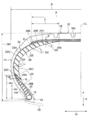
- FIG. 1 shows one side of a cross section along the tire axial direction of a run-flat radial tire (hereinafter, simply referred to as “tire”) 10 according to the embodiment.
- tire indicates the axial direction of the tire 10 (hereinafter referred to as “tire axial direction” as appropriate), and the arrow R indicates the radial direction of the tire 10 (hereinafter referred to as “tire radial direction” as appropriate).
- the symbol CL indicates the equator plane of the tire 10 (hereinafter referred to as “tire equator plane” as appropriate).
- the axis (rotation axis) side of the tire 10 along the tire radial direction is “inner side in the tire radial direction”, and the side opposite to the axis side of the tire 10 along the tire radial direction is “outer side in the tire radial direction”.
- the equatorial plane CL side of the tire 10 along the tire axial direction is referred to as “inner side in the tire axial direction”
- the side opposite to the equatorial plane CL side along the tire axial direction is referred to as “outer side in the tire axial direction”.
- the standard rim here is a rim defined in the Year 2013 edition of JATMA (Japan Automobile Tire Association).
- the standard air pressure is an air pressure corresponding to the maximum load capacity of Year Book 2013 version of JATMA (Japan Automobile Tire Association).
- the load is the maximum load (maximum load capacity) of a single wheel at the applicable size described in the following standard
- the internal pressure is the maximum load of a single wheel (specified in the following standard)
- the rim is a standard rim (or “Applied Rim” or “Recommended Rim”) in an applicable size described in the following standard.
- the standards are determined by industry standards that are valid in the region where the tire is produced or used. For example, in the United States, “The Tire and Rim Association Inc. Year Book” in Europe, in Europe “The European Tire and Rim Technical Standards Manual” in Japan, and in Japan, “Japan Tire” in Japan. Has been.
- the tire 10 of this embodiment should just be a tire whose tire cross-section height is 115 mm or more, for example, is a tire of 129 mm.
- the run-flat radial tire 10 includes a pair of bead portions 12 (only one bead portion 12 is shown in FIG. 1) and the pair of bead portions 12 outward in the tire radial direction.
- a pair of tire side portions 14 each extending and a tread portion 16 extending from one tire side portion 14 to the other tire side portion 14 are provided.
- the tire side part 14 bears the load which acts on the tire 10 at the time of run flat driving
- a bead core 18 is embedded in each of the pair of bead portions 12.
- a carcass 22 straddles the pair of bead cores 18. The end side of the carcass 22 is locked to the bead core 18. The end of the carcass 22 is folded around the bead core 18 from the inside of the tire to the outside, and the end 22C of the folded portion 22B is in contact with the carcass main body 22A. Further, the carcass 22 extends in a toroidal shape from one bead core 18 to the other bead core 18 to constitute a tire skeleton.
- the belt layers 24A and 24B are laminated on the outer side in the tire radial direction of the carcass main body portion 22A from the inner side in the tire radial direction, and the cap layer 24C is laminated thereon.
- Each of the belt layers 24A and 24B has a general configuration in which a plurality of steel cords are arranged in parallel with each other and rubber-coated, and the steel cord of the belt layer 24A and the steel cord of the second belt layer 24B are the equator. Inclined in the opposite direction to the surface CL and intersects each other.
- the belt layer 24A having a large width in the tire axial direction corresponds to the maximum width inclined belt layer.
- the width in the tire axial direction of the maximum width inclined belt layer (belt layer 24A) is preferably 90% or more and 115% or less of the tread width.
- the “tread width” refers to the width in the tire axial direction of the ground contact area under the maximum load when the tire 10 is assembled to the standard rim 30 and the internal pressure is set to the standard air pressure.
- the “maximum load load” is the maximum load load of Year Book 2013 version of JATMA (Japan Automobile Tire Association).
- a bead filler 20 extending from the bead core 18 to the outer side in the tire radial direction along the outer surface 220 of the carcass 22 is embedded.
- the bead filler 20 is disposed in a region surrounded by the carcass main body 22A and the folded portion 22B. Further, the bead filler 20 has a thickness that decreases toward the outer side in the tire radial direction, and an end portion 20 ⁇ / b> A on the outer side in the tire radial direction enters the tire side portion 14.
- the height BH of the bead filler 20 is preferably 30% to 50% of the tire cross-section height SH. In this embodiment, it is 42%.
- the “tire cross section height” is a length that is 1 ⁇ 2 of the difference between the tire outer diameter and the rim diameter in the no-load state, as defined by JATMA (Japan Automobile Tire Association) Year Book.
- the “bead filler height BH” refers to the end 20A of the bead filler 20 from the lower end (inner end in the tire radial direction) of the bead core 18 when the tire 10 is assembled to the standard rim 30 and the internal pressure is set to the standard air pressure. It indicates the length measured along the tire radial direction.
- the tire side portion 14 is provided with a side reinforcing rubber layer 26 that reinforces the tire side portion 14 on the inner side in the tire axial direction of the carcass 22.
- the side reinforcing rubber layer 26 extends in the tire radial direction along the inner surface 22I of the carcass 22.
- the side reinforcing rubber layer 26 has a shape that decreases in thickness toward the bead core 18 side and the tread portion 16 side, for example, a substantially crescent shape.
- the “thickness of the side reinforcing rubber layer” refers to the length measured along the normal line of the carcass 22 when the tire 10 is assembled to the standard rim 30 and the internal pressure is set to the standard air pressure. .
- the end portion 26A on the tread portion 16 side overlaps the belt layer 24A with the carcass 22 (carcass body portion 22A) interposed therebetween, and the end portion 26B on the bead core 18 side sandwiches the carcass 22 with the bead filler. 20 is formed to overlap.
- the overlapping width L in the tire axial direction of the side reinforcing rubber layer 26 and the belt layer 24A is set to 22.5% or more of the tire cross-section height SH.
- the thickness GB of the side reinforcing rubber layer 26 at the midpoint Q between the end 20A of the bead filler 20 and the end 26B of the side reinforcing rubber layer 26 along the extending direction of the carcass 22 is as follows.
- the thickness of the side reinforcing rubber layer 26 at the maximum width position of the carcass 22 is preferably 50% or less of the thickness GA (hereinafter sometimes referred to as the maximum thickness GA). In this embodiment, it is set to 30%.
- the “maximum width position of the carcass” refers to a position where the carcass 22 is the outermost in the tire axial direction.
- the thickness GC of the side reinforcing rubber layer 26 at the tire axial direction end E of the belt layer 24A which is the maximum width inclined belt layer is set to 70% or more of the maximum thickness GA.
- the thickness GD of the side reinforcing rubber layer 26 at the position P on the inner side in the tire axial direction by 14% of the tire cross-section height SH from the tire axial direction end E of the belt layer 24A may be 30% or more of the maximum thickness GA. It is preferable.
- the tire radial direction distance RH between the lower end (inner end in the tire radial direction) of the bead core 18 and the end 26B of the side reinforcing rubber layer 26 is preferably 50% to 80% of the bead filler height BH. . In this embodiment, it is 65%.
- Tire radial direction distance RH refers to the end of the side reinforcing rubber layer 26 from the lower end (inner end in the tire radial direction) of the bead core 18 when the tire 10 is assembled to the standard rim 30 and the internal pressure is set to the standard air pressure. It indicates the length measured along the tire radial direction up to 26B.
- the side reinforcing rubber layer 26 is a reinforcing rubber for running a predetermined distance while supporting the weight of the vehicle and the occupant when the internal pressure of the tire 10 decreases due to puncture or the like.
- the tread portion 16 has a plurality of circumferential grooves 16A extending in the tire circumferential direction.
- an inner liner mainly composed of butyl rubber (not shown) is disposed on the inner surface of the tire 10 from one bead portion 12 to the other bead portion 12.
- the inner liner may be mainly composed of a resin.
- the rim guard is not provided in this embodiment, but a rim guard may be provided.
- the mechanism of rim disengagement in the tire 10 will be briefly described.
- the overlap width L in the tire axial direction between the side reinforcing rubber layer 26 and the belt layer 24A which is the maximum width inclined belt layer is 14% (less than 22.5%) of the tire cross-section height SH.
- a tire 50 see FIG. 4 having the same configuration as the tire 10. Note that components that are substantially the same as those of the tire 10 are denoted by the same reference numerals.
- FIG. 5 it has been confirmed that the rim disengagement inside the turning of the vehicle is likely to occur in a tire having a tire cross-section height SH of 115 mm or more.
- the graph shown in FIG. 5 is obtained by examining the rim detachment index with respect to the tire cross-section height SH using a run-flat radial tire in which the tire width is 215 and the tire cross-section height SH is changed. The larger the is, the harder it is to remove the rim. According to FIG.
- the tire cross-section height SH is specifically 250 mm or less, particularly 155 mm or less.
- the overlap width L in the tire axial direction between the side reinforcing rubber layer 26 and the belt layer 24A is 22.5% or more of the tire cross-sectional height (see FIG. 1). Therefore, even when a slip angle is given during run-flat travel, the rigidity of the position P on the inner side in the tire axial direction is 14% of the tire cross-section height SH from the tire axial end E of the belt layer 24A that supports the load. Since it is improved, bending in the vicinity of the position P of the belt layer 24A is suppressed (see FIG. 2). Therefore, occurrence of buckling in the tire side portion 14 is suppressed, and an improvement in rim detachability can be achieved.
- a tire having a high tire side portion 14 (length along the tire radial direction), such as a tire having a tire cross-section height of 115 mm or more, is backed on the tire side portion 14 as in the tire 10 of the present embodiment. It is easy to cause a ring. For this reason, by setting the overlap width L in the tire axial direction between the side reinforcing rubber layer 26 and the belt layer 24A to 22.5% or more of the tire cross-section height with respect to the tire 10 having a tire cross-section height of 115 mm or more, Buckling of the tire side portion 14 can be effectively suppressed.
- the tire axial direction width A of the maximum width inclined belt layer (belt layer 24A) is 80% or more of the tire cross-sectional width B, the rigidity is improved in a wider range of the tread portion 16 and the bending is suppressed.
- the buckling of the side portion 14 can be suppressed and the rim detachability can be improved.
- buckling of the side portion can be further suppressed by expanding the overlapping width L of the side reinforcing rubber layer 26 and the belt layer 24A outward in the tire width direction.
- the thickness GD of the side reinforcing rubber layer 26 at the position P on the inner side in the tire axial direction by 14% of the tire cross-section height SH from the tire axial direction end E of the belt layer 24A is 30% or more of the maximum thickness GA.
- the occurrence of buckling can be further suppressed, and the rim detachability can be further improved.
- the thickness GC of the side reinforcing rubber layer 26 at the tire axial direction end E of the belt layer 24A that is the maximum width inclined belt layer is set to 70% or more of the maximum thickness GA.
- the bending rigidity in the vicinity of the tire axial direction end E of 24A can be further improved, and the rim detachability can be further improved.
- the height BH of the bead filler 20 is set to 42% (30% or more and 50% or less) of the tire cross-section height SH, both ride comfort and run flat durability can be achieved. That is, when the height BH of the bead filler 20 is less than 30% of the tire cross-section height SH, the rigidity of the bead portion 12 is low and easily deformed, so that the tire is easily damaged and the run-flat durability is reduced. . On the other hand, when the height BH of the bead filler 20 exceeds 50% of the tire cross-section height SH, the rigidity of the bead portion 12 is too high, and the ride comfort is lowered.
- the thickness of the side reinforcing rubber layer 26 is decreased as it goes toward the bead core 18 side and the tread portion 16 side, and the thickness GB of the side reinforcing rubber layer 26 at the midpoint Q of the overlapping portion 28 is reduced. Since the thickness GA of the side reinforcing rubber layer 26 at the maximum width position is 30% (50% or less), damage to the side reinforcing rubber layer 26 is suppressed even when side buckling occurs. This is because the distance from the carcass 22 to the inner surface 26C of the side reinforcing rubber layer 26 is shortened at the middle point Q of the overlapping portion 28, and this inner surface 26C (specifically, the portion corresponding to the overlapping portion 28 of the inner surface 26C). This is because the acting tensile stress is reduced.
- the tire radial direction distance RH between the lower end (inner end in the tire radial direction) of the bead core 18 and the end 26 ⁇ / b> B of the side reinforcing rubber layer 26 is 65% of the bead filler height BH (80% or more 80%). % Or less), it is possible to achieve both ride comfort and run-flat durability. That is, if the tire radial direction distance RH is less than 50% of the height BH, the rigidity of the bead portion 12 becomes too high, and the riding comfort is lowered. On the other hand, when the tire radial direction distance RH exceeds 80% of the height BH, the run-flat durability is deteriorated due to a decrease in the rigidity of the bead portion 12.
- the end portion side of the carcass 22 is folded around the bead core 18 from the inner side to the outer side in the tire axial direction, and the end portion of the carcass 22 is locked to the bead core 18.
- the embodiment is limited to this configuration.
- the bead core 18 may be halved, and the end of the carcass 22 may be sandwiched between the halved bead cores 18 so that the end of the carcass 22 is locked to the bead core 18.
- the side reinforcing rubber layer 26 is composed of one kind of rubber, but if the rubber is the main component, it may contain other fillers, short fibers, resins, and the like.
- the side reinforcing rubber layer 26 may be composed of a plurality of types of rubber.
- the side reinforcing rubber layer 26 may be configured by stacking a plurality of different types of rubber in the tire radial direction or the tire axial direction.
- the tire shaft of any side reinforcing rubber layer 26 and the belt layer 24A that is the maximum width inclined belt layer is 22.5% or more of the tire cross-section height SH.
- side reinforcing rubber layers 26 may be provided at a plurality of positions between the carcass 22 and between the carcass 22 and the inner liner.
- a reinforcing cord layer 24D may be provided.
- the cord constituting the reinforcing cord layer 24D is preferably provided so as to be inclined in the range of 60 ° or more and 90 ° or less with respect to the tire circumferential direction.
- the bending rigidity in the vicinity of the position P on the inner side in the tire axial direction is improved by 14% of the tire cross-section height SH from the tire axial direction end E of the belt layer 24A and the like, and the tire side portion 14 buckling can be further suppressed.
- the rubber member on the outer side in the tire axial direction of the carcass 22 of the tire side portion 14 is not specified in the present embodiment.
- the JIS hardness (20 ° C.) is 70 or more and 85 or less
- the loss coefficient tan ⁇ (60 (° C.) can include rubber having physical properties of 0.10 or less.
- this indication is not limited to such embodiment, and of course, it can implement in various modes in the range which does not deviate from the gist of this indication.
- the run-flat radial tire used in the test has a size of 215 / 60R17 and a tire cross-section height of 129 mm.
- the run-flat radial tires of Examples 1 to 12 all adopt the same structure as that of the tire 10 of the present embodiment described above, and the run-flat radial tires of Examples 1 to 5 are “maximum width inclined belts”. Tires having different values of “overlap width L with side reinforcing rubber layer” and “thickness GD of side reinforcing rubber layer at position P where the tire cross-section height SH ratio is 14% inward in the tire axial direction from the end of the maximum width inclined belt”. It is.
- run-flat radial tires of Examples 6 to 10 have the “thickness GC of the side reinforcing rubber layer at the end of the maximum inclined belt”, “the tire cross-section height SH ratio of 14 from the end of the maximum width inclined belt to the inside in the tire axial direction.
- the tires have different values of the thickness GD of the side reinforcing rubber layer at the position P of%.
- run flat tires of Examples 11 and 12 are tires having different values of “tire axial direction width A at the end of the maximum inclined belt layer”.
- the run flat radial tire of Comparative Example 1 has the same structure as the run flat radial tires of Examples 1 to 10, but the value of the overlap width L of the maximum width inclined belt and the side reinforcing rubber layer is disclosed in the present disclosure. This tire is not included in the range.
- Various numerical values of Examples 1 to 10 and Comparative Example are as shown in Tables 1 and 2.
- the run-flat radial tire of Comparative Example 2 has the same structure as the run-flat radial tires of Examples 11 and 12, but the value of the tire axial width A of the maximum width inclined belt layer is within the scope of the present disclosure. Tire not included.
- Various numerical values of Examples 11 and 12 and Comparative Example 2 are as shown in Table 3.
- test tire was assembled on a standard rim of JATMA standard, mounted on the vehicle without filling with air (with an internal pressure of 0 kPa), and ran for a distance of 5 km at a speed of 20 km / h.
- entering a turning circuit having a radius of curvature of 25 m at a predetermined speed and stopping at a position of 1/3 turn of this turning circuit was performed twice in succession (J-turn test).
- This J-turn test was carried out while increasing the approach speed by 2 km / h, and the turning acceleration when the bead part was detached from the rim (rim hump) was measured.
- the turning acceleration when the bead part of the comparative example was detached from the rim was taken as a reference value (100), and the turning acceleration when each bead part of Examples 1 to 12 was detached from the rim was expressed as an index and evaluated.
- “Rim detachability” in Tables 1 to 3 is an index that indicates the turning acceleration when the bead portion is detached from the rim.
- the numerical value of the rim detachability the larger the value, the better the result.
- the overlap width L between the side reinforcing rubber layer and the maximum width inclined belt layer is 40% (22.5% or more) of the tire cross-section height SH.
- the ratio (GC / GA) of the thickness GC of the side reinforcing rubber layer 26 at the tire axial direction end of the belt layer 24A that is the maximum width inclined belt layer with respect to the thickness GA of the side reinforcing rubber layer 26 at the carcass maximum width position is large. It was confirmed that the rim detachability was further improved. In particular, it was confirmed that GC / GA was 70% or more.
Abstract
Description
本発明は、ランフラットラジアルタイヤに関する。 This application claims the priority of Japanese Patent Application No. 2014-018920 filed on Feb. 3, 2014, the entirety of which is incorporated herein by reference.
The present invention relates to a run-flat radial tire.

実施例1~5では、サイド補強ゴム層と最大幅傾斜ベルト層とのタイヤ軸方向の重複幅Lをタイヤ断面高さSHの22.5%以上としているため、リム外れ性が向上したことが確認された。
In Examples 1 to 5, since the overlap width L in the tire axial direction between the side reinforcing rubber layer and the maximum width inclined belt layer is 22.5% or more of the tire cross-section height SH, the rim detachability is improved. confirmed.
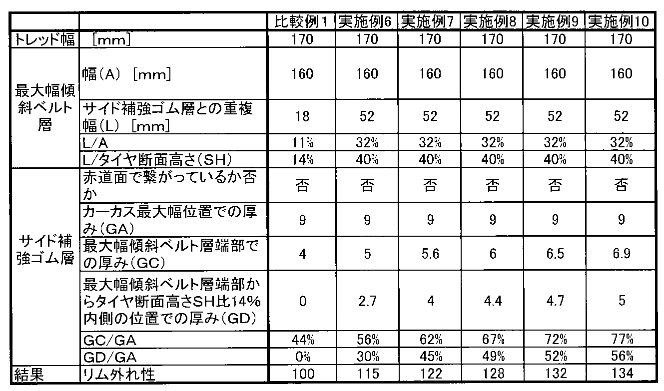
表2に示すように、実施例6~10では、サイド補強ゴム層と最大幅傾斜ベルト層の重複幅Lがタイヤ断面高さSHの40%(22.5%以上)のランフラットラジアルタイヤにおいて、カーカス最大幅位置におけるサイド補強ゴム層26の厚みGAに対する最大幅傾斜ベルト層であるベルト層24Aのタイヤ軸方向端部からタイヤ断面高さSHの14%だけタイヤ軸方向内側の位置Pにおけるサイド補強ゴム層26の厚みGDの割合(GD/GA)が大きいほど、リム外れ性が向上することが確認された。特に、GD/GAが30%以上であると良好なことが確認された。
As shown in Table 2, in Examples 6 to 10, in the run-flat radial tire, the overlap width L between the side reinforcing rubber layer and the maximum width inclined belt layer is 40% (22.5% or more) of the tire cross-section height SH. The side at the position P on the inner side in the tire axial direction by 14% of the tire cross-section height SH from the end in the tire axial direction of the

表3に示すように、実施例11、12では、最大幅傾斜ベルト層であるベルト層24Aのタイヤ軸方向幅Aがタイヤ断面幅Bの80%以上であると、リム外れ性が一層向上することが確認された。
As shown in Table 3, in Examples 11 and 12, when the tire axial direction width A of the
Claims (4)
- 一対のビード部間で跨るカーカスと、
タイヤサイド部に設けられ、前記カーカスの内面に沿ってタイヤ径方向に延びるサイド補強ゴム層と、
前記カーカスのタイヤ径方向外側に設けられ、タイヤ周方向に対して傾斜する方向に延びるコードを備え、タイヤ軸方向の幅が最も大きい最大幅傾斜ベルト層と前記サイド補強ゴム層の前記タイヤ軸方向の重複幅が、前記最大幅傾斜ベルト層の少なくとも一方のタイヤ軸方向の端部側で、タイヤ断面高さの22.5%以上である少なくとも一層の傾斜ベルト層と、
を備えるタイヤ断面高さが115mm以上であるランフラットラジアルタイヤ。 A carcass straddling between a pair of bead parts;
A side reinforcing rubber layer provided in the tire side portion and extending in the tire radial direction along the inner surface of the carcass;
The tire is provided on the outer side in the tire radial direction of the carcass and includes a cord extending in a direction inclined with respect to the tire circumferential direction, and the maximum width inclined belt layer having the largest width in the tire axial direction and the tire axial direction of the side reinforcing rubber layer At least one inclined belt layer having an overlap width of 22.5% or more of the tire cross-section height on the end side in the tire axial direction of at least one of the maximum width inclined belt layers;
A run-flat radial tire having a tire cross-section height of 115 mm or more. - 前記最大幅傾斜ベルト層のタイヤ軸方向端部を通る前記カーカスの法線上で測った前記サイド補強ゴム層の厚みが、前記カーカスの最大幅位置におけるサイド補強ゴム層の厚みの70%以上である請求項1記載のランフラットラジアルタイヤ。 The thickness of the side reinforcing rubber layer measured on the normal line of the carcass passing through the tire axial end of the maximum width inclined belt layer is 70% or more of the thickness of the side reinforcing rubber layer at the maximum width position of the carcass. The run-flat radial tire according to claim 1.
- 前記最大幅傾斜ベルト層のタイヤ軸方向端部からタイヤ断面高さの14%だけタイヤ軸方向内側の位置を通る前記カーカスの法線上で測った前記サイド補強ゴム層の厚みが、前記カーカスの最大幅位置におけるサイド補強ゴム層の厚みの30%以上である請求項1又は2記載のランフラットラジアルタイヤ。 The thickness of the side reinforcing rubber layer measured on the normal line of the carcass passing through a position on the inner side in the tire axial direction by 14% of the tire cross-section height from the tire axial end of the maximum width inclined belt layer is the maximum thickness of the carcass. The run-flat radial tire according to claim 1 or 2, wherein the run-flat radial tire is 30% or more of a thickness of the side reinforcing rubber layer at a large position.
- 前記最大幅傾斜ベルト層のタイヤ軸方向幅がタイヤ断面幅の80%以上である請求項1~3のいずれか1項記載のランフラットラジアルタイヤ。 The run-flat radial tire according to any one of claims 1 to 3, wherein a width in a tire axial direction of the maximum width inclined belt layer is 80% or more of a tire cross-sectional width.
Priority Applications (5)
| Application Number | Priority Date | Filing Date | Title |
|---|---|---|---|
| AU2015212144A AU2015212144B2 (en) | 2014-02-03 | 2015-01-13 | Run-flat radial tyre |
| US15/116,216 US20190152274A1 (en) | 2014-02-03 | 2015-01-13 | Run-flat radial tire |
| CN201580007130.0A CN105960342B (en) | 2014-02-03 | 2015-01-13 | Run-flat radial |
| EP15742827.7A EP3103659A4 (en) | 2014-02-03 | 2015-01-13 | Run-flat radial tire |
| ZA2016/05555A ZA201605555B (en) | 2014-02-03 | 2016-08-10 | Run-flat radial tire |
Applications Claiming Priority (2)
| Application Number | Priority Date | Filing Date | Title |
|---|---|---|---|
| JP2014-018920 | 2014-02-03 | ||
| JP2014018920A JP6454471B2 (en) | 2014-02-03 | 2014-02-03 | Run-flat radial tire |
Publications (1)
| Publication Number | Publication Date |
|---|---|
| WO2015115162A1 true WO2015115162A1 (en) | 2015-08-06 |
Family
ID=53756739
Family Applications (1)
| Application Number | Title | Priority Date | Filing Date |
|---|---|---|---|
| PCT/JP2015/050643 WO2015115162A1 (en) | 2014-02-03 | 2015-01-13 | Run-flat radial tire |
Country Status (7)
| Country | Link |
|---|---|
| US (1) | US20190152274A1 (en) |
| EP (1) | EP3103659A4 (en) |
| JP (1) | JP6454471B2 (en) |
| CN (1) | CN105960342B (en) |
| AU (1) | AU2015212144B2 (en) |
| WO (1) | WO2015115162A1 (en) |
| ZA (1) | ZA201605555B (en) |
Cited By (3)
| Publication number | Priority date | Publication date | Assignee | Title |
|---|---|---|---|---|
| US20160144670A1 (en) * | 2013-06-13 | 2016-05-26 | Bridgestone Corporation | Run-flat tire |
| US20170197477A1 (en) * | 2016-01-08 | 2017-07-13 | Sumitomo Rubber Industries, Ltd. | Pneumatic tire |
| WO2021229976A1 (en) * | 2020-05-15 | 2021-11-18 | 横浜ゴム株式会社 | Pneumatic tire |
Families Citing this family (4)
| Publication number | Priority date | Publication date | Assignee | Title |
|---|---|---|---|---|
| JP6347979B2 (en) * | 2014-04-18 | 2018-06-27 | 株式会社ブリヂストン | Side-reinforced run-flat radial tire |
| JP6519623B2 (en) * | 2017-10-02 | 2019-05-29 | 横浜ゴム株式会社 | Run flat tire |
| CN109501530B (en) * | 2018-10-15 | 2021-08-06 | 安徽佳通乘用子午线轮胎有限公司 | Run-flat tire with improved durability |
| JP7352449B2 (en) * | 2019-11-15 | 2023-09-28 | 株式会社ブリヂストン | run flat tires |
Citations (8)
| Publication number | Priority date | Publication date | Assignee | Title |
|---|---|---|---|---|
| JPH10138720A (en) * | 1996-11-13 | 1998-05-26 | Bridgestone Corp | Pneumatic tire |
| JP2001063324A (en) * | 1999-08-31 | 2001-03-13 | Bridgestone Corp | Pneumatic tire |
| JP2001322410A (en) * | 2000-05-17 | 2001-11-20 | Ohtsu Tire & Rubber Co Ltd :The | Pneumatic tire |
| JP2009126262A (en) | 2007-11-21 | 2009-06-11 | Bridgestone Corp | Run flat tire |
| JP2011084146A (en) * | 2009-10-14 | 2011-04-28 | Bridgestone Corp | Run-flat tire |
| JP2013060075A (en) * | 2011-09-13 | 2013-04-04 | Yokohama Rubber Co Ltd:The | Pneumatic tire |
| JP2013095211A (en) * | 2011-10-31 | 2013-05-20 | Sumitomo Rubber Ind Ltd | Pneumatic tire |
| JP2014018920A (en) | 2012-07-19 | 2014-02-03 | Fujibo Holdings Inc | Polishing pad, and method for forming the same |
Family Cites Families (11)
| Publication number | Priority date | Publication date | Assignee | Title |
|---|---|---|---|---|
| JPS53138106A (en) * | 1976-10-02 | 1978-12-02 | Toyo Tire & Rubber Co Ltd | Pneumatic safety tire |
| JPH0911714A (en) * | 1995-06-28 | 1997-01-14 | Bridgestone Corp | Pneumatic radial tire |
| JPH11227425A (en) * | 1998-02-18 | 1999-08-24 | Bridgestone Corp | Pneumatic safety tire |
| JP2000043518A (en) * | 1998-07-27 | 2000-02-15 | Bridgestone Corp | Pneumatic radial tire |
| JP5038624B2 (en) * | 2005-08-08 | 2012-10-03 | 住友ゴム工業株式会社 | Run flat tire |
| US20070069890A1 (en) * | 2005-09-28 | 2007-03-29 | Tuck Edward F | Personal radio location system |
| FR2925393B1 (en) * | 2007-12-21 | 2009-12-18 | Michelin Soc Tech | PNEUMATIC TIRE FOR FLAT ROLL WITH ADDITIONAL FLANK REINFORCEMENT. |
| JP5457415B2 (en) * | 2011-09-15 | 2014-04-02 | 住友ゴム工業株式会社 | Run flat tire |
| JP5589015B2 (en) * | 2012-02-27 | 2014-09-10 | 住友ゴム工業株式会社 | Pneumatic tire |
| JP5809611B2 (en) * | 2012-08-20 | 2015-11-11 | 住友ゴム工業株式会社 | Run flat tire |
| JP2015151019A (en) * | 2014-02-14 | 2015-08-24 | 株式会社ブリヂストン | run-flat radial tire |
-
2014
- 2014-02-03 JP JP2014018920A patent/JP6454471B2/en active Active
-
2015
- 2015-01-13 AU AU2015212144A patent/AU2015212144B2/en active Active
- 2015-01-13 US US15/116,216 patent/US20190152274A1/en not_active Abandoned
- 2015-01-13 CN CN201580007130.0A patent/CN105960342B/en active Active
- 2015-01-13 WO PCT/JP2015/050643 patent/WO2015115162A1/en active Application Filing
- 2015-01-13 EP EP15742827.7A patent/EP3103659A4/en not_active Withdrawn
-
2016
- 2016-08-10 ZA ZA2016/05555A patent/ZA201605555B/en unknown
Patent Citations (8)
| Publication number | Priority date | Publication date | Assignee | Title |
|---|---|---|---|---|
| JPH10138720A (en) * | 1996-11-13 | 1998-05-26 | Bridgestone Corp | Pneumatic tire |
| JP2001063324A (en) * | 1999-08-31 | 2001-03-13 | Bridgestone Corp | Pneumatic tire |
| JP2001322410A (en) * | 2000-05-17 | 2001-11-20 | Ohtsu Tire & Rubber Co Ltd :The | Pneumatic tire |
| JP2009126262A (en) | 2007-11-21 | 2009-06-11 | Bridgestone Corp | Run flat tire |
| JP2011084146A (en) * | 2009-10-14 | 2011-04-28 | Bridgestone Corp | Run-flat tire |
| JP2013060075A (en) * | 2011-09-13 | 2013-04-04 | Yokohama Rubber Co Ltd:The | Pneumatic tire |
| JP2013095211A (en) * | 2011-10-31 | 2013-05-20 | Sumitomo Rubber Ind Ltd | Pneumatic tire |
| JP2014018920A (en) | 2012-07-19 | 2014-02-03 | Fujibo Holdings Inc | Polishing pad, and method for forming the same |
Non-Patent Citations (2)
| Title |
|---|
| "Year Book", 2013, JAPAN AUTOMOBILE TIRE MANUFACTURERS ASSOCIATION (JATMA |
| See also references of EP3103659A4 * |
Cited By (5)
| Publication number | Priority date | Publication date | Assignee | Title |
|---|---|---|---|---|
| US20160144670A1 (en) * | 2013-06-13 | 2016-05-26 | Bridgestone Corporation | Run-flat tire |
| US10112446B2 (en) * | 2013-06-13 | 2018-10-30 | Bridgestone Corporation | Run-flat tire |
| US20170197477A1 (en) * | 2016-01-08 | 2017-07-13 | Sumitomo Rubber Industries, Ltd. | Pneumatic tire |
| US10744826B2 (en) * | 2016-01-08 | 2020-08-18 | Sumitomo Rubber Industries, Ltd. | Pneumatic tire |
| WO2021229976A1 (en) * | 2020-05-15 | 2021-11-18 | 横浜ゴム株式会社 | Pneumatic tire |
Also Published As
| Publication number | Publication date |
|---|---|
| CN105960342B (en) | 2018-03-30 |
| JP2015145176A (en) | 2015-08-13 |
| ZA201605555B (en) | 2019-07-31 |
| US20190152274A1 (en) | 2019-05-23 |
| AU2015212144A2 (en) | 2016-09-01 |
| JP6454471B2 (en) | 2019-01-16 |
| AU2015212144B2 (en) | 2017-12-07 |
| EP3103659A4 (en) | 2017-03-15 |
| CN105960342A (en) | 2016-09-21 |
| AU2015212144A1 (en) | 2016-09-01 |
| EP3103659A1 (en) | 2016-12-14 |
Similar Documents
| Publication | Publication Date | Title |
|---|---|---|
| JP6454472B2 (en) | Run-flat radial tire | |
| WO2015115162A1 (en) | Run-flat radial tire | |
| JP6377390B2 (en) | Run-flat radial tire | |
| JP6411059B2 (en) | Side-reinforced run-flat radial tires for passenger cars | |
| WO2015125387A1 (en) | Run-flat tire | |
| JP6347979B2 (en) | Side-reinforced run-flat radial tire | |
| JP2015214306A (en) | Run-flat tire | |
| WO2014199756A1 (en) | Run-flat tire | |
| WO2015064135A1 (en) | Run-flat radial tire | |
| JP6162023B2 (en) | Run-flat radial tire | |
| JP2015214307A (en) | Run-flat tire | |
| JP6268037B2 (en) | Run-flat radial tire | |
| JP6274815B2 (en) | Run-flat radial tire |
Legal Events
| Date | Code | Title | Description |
|---|---|---|---|
| 121 | Ep: the epo has been informed by wipo that ep was designated in this application |
Ref document number: 15742827 Country of ref document: EP Kind code of ref document: A1 |
|
| NENP | Non-entry into the national phase |
Ref country code: DE |
|
| REEP | Request for entry into the european phase |
Ref document number: 2015742827 Country of ref document: EP |
|
| WWE | Wipo information: entry into national phase |
Ref document number: 2015742827 Country of ref document: EP |
|
| ENP | Entry into the national phase |
Ref document number: 2015212144 Country of ref document: AU Date of ref document: 20150113 Kind code of ref document: A |