JP2015151019A - run-flat radial tire - Google Patents
run-flat radial tire Download PDFInfo
- Publication number
- JP2015151019A JP2015151019A JP2014026752A JP2014026752A JP2015151019A JP 2015151019 A JP2015151019 A JP 2015151019A JP 2014026752 A JP2014026752 A JP 2014026752A JP 2014026752 A JP2014026752 A JP 2014026752A JP 2015151019 A JP2015151019 A JP 2015151019A
- Authority
- JP
- Japan
- Prior art keywords
- tire
- width direction
- run
- width
- tread
- Prior art date
- Legal status (The legal status is an assumption and is not a legal conclusion. Google has not performed a legal analysis and makes no representation as to the accuracy of the status listed.)
- Pending
Links
Images


Classifications
-
- B—PERFORMING OPERATIONS; TRANSPORTING
- B60—VEHICLES IN GENERAL
- B60C—VEHICLE TYRES; TYRE INFLATION; TYRE CHANGING; CONNECTING VALVES TO INFLATABLE ELASTIC BODIES IN GENERAL; DEVICES OR ARRANGEMENTS RELATED TO TYRES
- B60C17/00—Tyres characterised by means enabling restricted operation in damaged or deflated condition; Accessories therefor
- B60C17/0009—Tyres characterised by means enabling restricted operation in damaged or deflated condition; Accessories therefor comprising sidewall rubber inserts, e.g. crescent shaped inserts
-
- B—PERFORMING OPERATIONS; TRANSPORTING
- B60—VEHICLES IN GENERAL
- B60C—VEHICLE TYRES; TYRE INFLATION; TYRE CHANGING; CONNECTING VALVES TO INFLATABLE ELASTIC BODIES IN GENERAL; DEVICES OR ARRANGEMENTS RELATED TO TYRES
- B60C15/00—Tyre beads, e.g. ply turn-up or overlap
- B60C15/0009—Tyre beads, e.g. ply turn-up or overlap features of the carcass terminal portion
- B60C15/0036—Tyre beads, e.g. ply turn-up or overlap features of the carcass terminal portion with high ply turn-up, i.e. folded around the bead core and terminating radially above the point of maximum section width
- B60C15/0045—Tyre beads, e.g. ply turn-up or overlap features of the carcass terminal portion with high ply turn-up, i.e. folded around the bead core and terminating radially above the point of maximum section width with ply turn-up up to the belt edges, i.e. folded around the bead core and extending to the belt edges
-
- B—PERFORMING OPERATIONS; TRANSPORTING
- B60—VEHICLES IN GENERAL
- B60C—VEHICLE TYRES; TYRE INFLATION; TYRE CHANGING; CONNECTING VALVES TO INFLATABLE ELASTIC BODIES IN GENERAL; DEVICES OR ARRANGEMENTS RELATED TO TYRES
- B60C3/00—Tyres characterised by the transverse section
- B60C3/04—Tyres characterised by the transverse section characterised by the relative dimensions of the section, e.g. low profile
-
- B—PERFORMING OPERATIONS; TRANSPORTING
- B60—VEHICLES IN GENERAL
- B60C—VEHICLE TYRES; TYRE INFLATION; TYRE CHANGING; CONNECTING VALVES TO INFLATABLE ELASTIC BODIES IN GENERAL; DEVICES OR ARRANGEMENTS RELATED TO TYRES
- B60C9/00—Reinforcements or ply arrangement of pneumatic tyres
- B60C9/18—Structure or arrangement of belts or breakers, crown-reinforcing or cushioning layers
- B60C9/28—Structure or arrangement of belts or breakers, crown-reinforcing or cushioning layers characterised by the belt or breaker dimensions or curvature relative to carcass
Abstract
Description
本発明は、ランフラットラジアルタイヤに関する。 The present invention relates to a run-flat radial tire.
パンクなどで内圧が低下した状態でも一定距離を安全に走行可能にするランフラットラジアルタイヤとして、タイヤサイド部をサイド補強ゴムで補強したサイド補強型のランフラットラジアルタイヤが知られている(例えば、特許文献1参照)。 As a run flat radial tire that can safely travel a certain distance even when the internal pressure is reduced due to puncture or the like, a side reinforcing type run flat radial tire in which a tire side portion is reinforced with a side reinforcing rubber is known (for example, Patent Document 1).
ところで、サイド補強型のランフラットラジアルタイヤでは、内圧が低下した状態での走行時(ランフラット走行時)に、車両が旋回するなどしてSA(スリップアングル)が付与された場合、タイヤサイド部がタイヤ内側に折れ曲がるバックリング現象が発生することがある。 By the way, in the side-reinforced run-flat radial tire, when SA (slip angle) is given by turning the vehicle or the like when running with the internal pressure reduced (run-flat running), the tire side portion There may be a buckling phenomenon in which the tire bends inside the tire.
本発明は、ランフラット走行時にタイヤサイド部にバックリング現象が発生するのを抑制できるランフラットラジアルタイヤを提供することを目的とする。 An object of this invention is to provide the run flat radial tire which can suppress that a buckling phenomenon generate | occur | produces in a tire side part at the time of run flat driving | running | working.
本発明の請求項1に記載のランフラットラジアルタイヤは、一対のビード部間に跨るカーカスと、前記カーカスのタイヤ径方向外側に設けられ、タイヤ周方向に対して傾斜する方向に延びるコードを備える少なくとも1枚のベルトプライによって構成された傾斜ベルト層と、前記傾斜ベルト層のタイヤ径方向外側に設けられ、踏面にタイヤ周方向に延びる周方向溝が複数形成されたトレッド部と、前記ビード部と前記トレッド部とを連結するタイヤサイド部に設けられ、前記カーカスの内面に沿って前記ビード部側から前記トレッド部側へ延びて最大幅の前記ベルトプライと重なり、前記最大幅のベルトプライとのタイヤ幅方向に沿った重複幅がタイヤ断面高さの20%以上の長さとされ、前記トレッド部側の端部がタイヤ幅方向最外側の前記周方向溝の溝底よりもタイヤ幅方向外側に配置されたサイド補強層と、を有している。 A run-flat radial tire according to a first aspect of the present invention includes a carcass straddling between a pair of bead portions, and a cord provided on the outer side in the tire radial direction of the carcass and extending in a direction inclined with respect to the tire circumferential direction. An inclined belt layer constituted by at least one belt ply, a tread portion provided on the outer side in the tire radial direction of the inclined belt layer and formed with a plurality of circumferential grooves extending in the tire circumferential direction on the tread surface, and the bead portion And a tire side portion connecting the tread portion, extending from the bead portion side to the tread portion side along the inner surface of the carcass and overlapping the maximum width belt ply, the maximum width belt ply, The overlap width along the tire width direction is 20% or more of the tire cross-section height, and the end on the tread portion side is the front of the outermost side in the tire width direction. Has a side reinforcing layer disposed outside in the tire width direction, the than the groove bottom of the circumferential groove.
請求項1に記載のランフラットラジアルタイヤでは、タイヤサイド部にカーカスの内面に沿ってビード部側からトレッド部側へ延びて最大幅(タイヤ幅方向に沿った幅が最大)のベルトプライと重なるサイド補強層を設けている。ここで、サイド補強層と最大幅のベルトプライとのタイヤ幅方向に沿った重複幅をタイヤ断面高さの20%以上の長さにしていることから、バックリング現象の起点となるトレッド端部近傍の剛性を高めることができる。これにより、ランフラット走行時に、タイヤサイド部にバックリング現象が発生するのを抑制できる。なお、ここでいう「タイヤ断面高さ」とは、JATMA(日本自動車タイヤ協会)のYear Book2014年度版で定義されるように、タイヤ外径とリム径との差の1/2の長さを指す。また、傾斜ベルト層が1枚のベルトプライで構成される場合には、1枚のベルトプライを最大幅のベルトプライとする。 In the run flat radial tire according to claim 1, the belt side ply extends along the inner surface of the carcass from the bead portion side to the tread portion side and overlaps with the belt ply having the maximum width (the width along the tire width direction is maximum). A side reinforcing layer is provided. Here, the overlap width along the tire width direction of the side reinforcing layer and the maximum width belt ply is set to a length of 20% or more of the tire cross-section height, so that the tread end that becomes the starting point of the buckling phenomenon The rigidity in the vicinity can be increased. Thereby, it is possible to suppress the occurrence of a buckling phenomenon at the tire side portion during run flat traveling. As used herein, the “tire cross-section height” is defined as 1/2 of the difference between the tire outer diameter and the rim diameter, as defined in the year 2014 edition of JATMA (Japan Automobile Tire Association) Point to. When the inclined belt layer is composed of a single belt ply, the single belt ply is the maximum width belt ply.
また、請求項1に記載のランフラットラジアルタイヤでは、サイド補強層のトレッド部側の端部をタイヤ幅方向最外側の周方向溝の溝底よりもタイヤ幅方向外側に配置している。言い換えると、サイド補強層をタイヤ幅方向最外側の周方向溝の溝底のタイヤ径方向内側に配置しないため、ランフラット走行時にタイヤ幅方向最外側の周方向溝の溝底を起点としてトレッド部がタイヤ幅方向に折れ曲がったとしても、このトレッド部の折れ曲がりにともなう入力がサイド補強層に作用するのが抑制される。これにより、ランフラット走行時におけるサイド補強層の耐久性が向上し、長期に亘ってタイヤサイド部にバックリング現象が発生するのを抑制できる。 In the run flat radial tire according to the first aspect, the end portion of the side reinforcing layer on the tread portion side is disposed on the outer side in the tire width direction than the groove bottom of the circumferential groove on the outermost side in the tire width direction. In other words, since the side reinforcing layer is not disposed on the inner side in the tire radial direction of the groove bottom of the outermost circumferential groove in the tire width direction, the tread portion starts from the groove bottom of the outermost circumferential groove in the tire width direction during run flat running. Even if the tire is bent in the tire width direction, it is possible to prevent the input accompanying the bending of the tread portion from acting on the side reinforcing layer. Thereby, durability of the side reinforcement layer at the time of run-flat traveling is improved, and occurrence of a buckling phenomenon in the tire side portion can be suppressed over a long period of time.
本発明の請求項2に記載のランフラットラジアルタイヤは、請求項1に記載のランフラットラジアルタイヤであって、タイヤ幅方向断面において、前記サイド補強層の前記トレッド部側の端部は、タイヤ幅方向最外側の前記周方向溝の溝底とタイヤ幅方向外側の溝壁との交点からタイヤ幅方向に沿ってトレッド半幅の3%以上離間した位置に配置されている。
The run-flat radial tire according to
請求項2に記載のランフラットラジアルタイヤでは、タイヤ幅方向断面において、サイド補強層のトレッド部側の端部をタイヤ幅方向最外側の周方向溝の溝底とタイヤ幅方向外側の溝壁との交点からタイヤ幅方向に沿ってトレッド半幅の3%以上離間した位置に配置している。このため、トレッド部がタイヤ幅方向最外側の周方向溝の溝底を起点として折れ曲がったとしても、このトレッド部の折れ曲がりにともなう入力がサイド補強層に作用するのが効果的に抑制される。
なお、ここでいう「溝底と溝壁との交点」とは、タイヤ幅方向断面において、周方向溝の隅部が湾曲している場合には、周方向溝の溝底(溝底面)の延長線と溝壁(溝壁面)の延長線との交点を指し、周方向溝の隅部が角張っている場合には、周方向溝の溝底(溝底面)と溝壁(溝壁面)との交点を指す。
In the run-flat radial tire according to
The “intersection of the groove bottom and the groove wall” as used herein refers to the groove bottom (groove bottom) of the circumferential groove when the corner of the circumferential groove is curved in the cross section of the tire width direction. The point of intersection of the extension line and the extension line of the groove wall (groove wall surface), and when the corner of the circumferential groove is square, the groove bottom (groove bottom surface) and groove wall (groove wall surface) of the circumferential groove The point of intersection.
本発明の請求項3に記載のランフラットラジアルタイヤは、請求項1又は請求項2に記載のランフラットラジアルタイヤであって、タイヤ断面高さが115mm以上である。
The run-flat radial tire according to
請求項3に記載のランフラットラジアルタイヤでは、タイヤ断面高さ(セクションハイト)が115mm以上のランフラットラジアルタイヤは、タイヤサイド部が曲がりやすくなっているが、このようなランフラットラジアルタイヤであってもバックリング現象の発生を抑制できる。
In the run flat radial tire according to
本発明のランフラットラジアルタイヤは、ランフラット走行時にタイヤサイド部にバックリング現象が発生するのを抑制できる。 The run flat radial tire of the present invention can suppress the occurrence of a buckling phenomenon at the tire side portion during run flat running.
以下、本発明のランフラットラジアルタイヤの一実施形態を図面に基づき説明する。
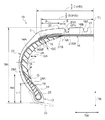
図1には、本実施形態のランフラットラジアルタイヤ10(以下、「タイヤ10」と称する。)のタイヤ幅方向に沿って切断した切断面の片側が示されている。なお、図中矢印TWはタイヤ10の幅方向(タイヤ幅方向)を示し、矢印TRはタイヤ10の径方向(タイヤ径方向)を示す。ここでいうタイヤ幅方向とは、タイヤ10の回転軸と平行な方向を指し、タイヤ軸方向ともいう。また、タイヤ径方向とは、タイヤ10の回転軸と直交する方向をいう。また、符号CLはタイヤ10の赤道(タイヤ赤道)を示している。
Hereinafter, an embodiment of a run flat radial tire of the present invention will be described with reference to the drawings.
FIG. 1 shows one side of a cut surface cut along the tire width direction of a run-flat radial tire 10 (hereinafter referred to as “
また、本実施形態では、タイヤ径方向に沿ってタイヤ10の回転軸側を「タイヤ径方向内側」、タイヤ径方向に沿ってタイヤ10の回転軸と反対側を「タイヤ径方向外側」と記載する。一方、タイヤ幅方向に沿ってタイヤ赤道CL側を「タイヤ幅方向内側」、タイヤ幅方向に沿ってタイヤ赤道CLと反対側を「タイヤ幅方向外側」と記載する。
Further, in the present embodiment, the rotation axis side of the
図1では、標準リム30(図1では、二点鎖線で示している。)に装着して標準空気圧を充填したときのタイヤ10を示している。ここでいう「標準リム」とは、JATMA(日本自動車タイヤ協会)のYear Book2014年度版規定のリムを指す。また、上記標準空気圧とは、JATMA(日本自動車タイヤ協会)のYear Book2013年度版の最大負荷能力に対応する空気圧である。
FIG. 1 shows the
なお、以下の説明において、荷重とは下記規格に記載されている適用サイズにおける単輪の最大荷重(最大負荷能力)のことであり、内圧とは下記規格に記載されている単輪の最大荷重(最大負荷能力)に対応する空気圧のことであり、リムとは下記規格に記載されている適用サイズにおける標準リム(または、”Approved Rim”、”Recommended Rim”)のことである。規格は、タイヤが生産又は使用される地域に有効な産業規格によって決められている。例えば、アメリカ合衆国では、”The Tire and Rim Association Inc.のYear Book ”で、欧州では”The European Tire and Rim Technical OrganizationのStandards Manual”で、日本では日本自動車タイヤ協会の“JATMA Year Book”にて規定されている。 In the following explanation, the load is the maximum load (maximum load capacity) of a single wheel at the applicable size described in the following standard, and the internal pressure is the maximum load of a single wheel described in the following standard. The rim refers to a standard rim (or “Applied Rim” or “Recommended Rim”) in an applicable size described in the following standard. The standards are determined by industry standards that are valid in the region where the tire is produced or used. For example, in the United States, “The Tire and Rim Association Inc. Year Book”, in Europe “The European Tire and Rim Technical Standards Standards” in the Japan Automobile Association of Japan Has been.
図1に示されるように、タイヤ10は、左右一対のビード部12(図1では、片側のビード部12のみ図示)と、一対のビード部12間をトロイド状に跨るカーカス14と、カーカス14よりもタイヤ径方向外側に設けられた傾斜ベルト層16、ベルト補強層17及び補強コード層18と、傾斜ベルト層16よりもタイヤ径方向外側に設けられてタイヤ10の外周部を構成するトレッド部20と、ビード部12とトレッド部20とを連結するタイヤサイド部22と、タイヤサイド部22に設けられたサイド補強層の一例としてのサイド補強ゴム24と、を備えている。
また、本実施形態のタイヤ10は、セクションハイトSHが115mm以上に設定されている。なお、ここでいうセクションハイト(タイヤ断面高さ)SHとは、タイヤ10を標準リム30に組み付けて内圧を標準空気圧とした状態におけるタイヤ外径とリム径との差の1/2の長さを指す。また、本実施形態では、タイヤ10のセクションハイトSHを115mm以上に設定しているが、本発明はこの構成に限定されず、セクションハイトSHを115mmよりも低く設定してもよい。
As shown in FIG. 1, the
In the
一対のビード部12には、ビードコア26がそれぞれ埋設されている。これらのビードコア26には、カーカス14が跨っている。
A
カーカス14は、1枚又は複数枚のカーカスプライによって構成されており、カーカスプライは、複数本のコード(例えば、有機繊維コードや金属コードなど)を被覆ゴムで被覆して形成されている。このようにして形成されたカーカス14が一方のビードコア26から他方のビードコア26へトロイド状に延びてタイヤの骨格を構成している。また、カーカス14の一端部及び他端部は、ビードコア26周りにタイヤ内側から外側へ折り返されて後述するトレッド部20まで延びている。なお、本実施形態では、カーカス14の一端部及び他端部をトレッド部20まで延ばしているが、本発明はこの構成に限定されず、カーカス14の一端部及び他端部をタイヤサイド部22まで延ばす、すなわち、タイヤサイド部22内に配置する構成としてもよい。
The
また、本実施形態では、カーカス14の一端部及び他端部をビードコア26周りに折り返してカーカス14をビードコア26に係止させているが、本発明はこの構成に限定されず、例えば、ビード部12に複数のビードコア片を配置して、この複数のビードコア片でカーカス14の一端部及び他端部を挟み込んでカーカス14をビードコア26に係止させてもよい。
In the present embodiment, one end and the other end of the
ビード部12のカーカス14で囲まれた領域には、ビードコア26からタイヤ径方向外側へ延びるビードフィラー28が埋設されている。ビードフィラー28は、タイヤ径方向外側の端部28Aがタイヤサイド部22に入り込んでおり、タイヤ径方向外側に向けて厚みが減少している。
A
また、ビードフィラー28の高さBHは、セクションハイトSHの30%〜50%の範囲内に設定されている。なお、ここでいうビードフィラー28の高さBHとは、タイヤ10を標準リム30に組み付けて内圧を標準空気圧とした状態におけるビードフィラー28のタイヤ径方向外側の端部28Aからビード部12の先端までの高さ(タイヤ径方向に沿った長さ)を指す。ここで、ビードフィラー28の高さBHがセクションハイトSHの30%より低い場合には、ランフラット走行時の耐久性を十分に確保できない。また、ビードフィラー28の高さBHがセクションハイトSHの50%より高い場合には、乗り心地が悪化する。このため、ビードフィラー28の高さBHは、セクションハイトSHの30%〜50%の範囲内で設定するのが好ましい。
Further, the height BH of the
また、本実施形態では、ビードフィラー28の端部28Aをタイヤ10の最大幅位置よりもタイヤ径方向内側に配置している。なお、ここでいうタイヤ10の最大幅位置とは、タイヤ10のタイヤ幅方向に沿って最も幅が広い位置を指している。
In the present embodiment, the
カーカス14のタイヤ径方向外側には、傾斜ベルト層16が配設されている。この傾斜ベルト層16は、1枚又は複数枚のベルトプライによって構成されている。このベルトプライは、複数本のコード(例えば、有機繊維コードや金属コードなど)を被覆ゴムで被覆して形成されている。ベルトプライを構成するコードは、タイヤ周方向に対して傾斜する方向に延びている。なお、本実施形態の傾斜ベルト層16は、2枚のベルトプライ16A、16Bで構成されている。
ベルトプライ16Aは、ベルトプライ16Bのタイヤ径方向内側に配置されている。また、ベルトプライ16Aは、タイヤ幅方向に沿った幅がベルトプライ16Bのタイヤ幅方向に沿った幅よりも狭くされている。なお、本実施形態のベルトプライ16Aは、本発明の最大幅のベルトプライの一例である。
An
The belt ply 16A is disposed on the inner side in the tire radial direction of the belt ply 16B. Further, the belt ply 16A has a width along the tire width direction that is narrower than a width along the tire width direction of the belt ply 16B. The
傾斜ベルト層16のタイヤ径方向外側には、ベルト補強層17が設けられている。このベルト補強層17は、傾斜ベルト層16の全体を覆っている。また、ベルト補強層17のタイヤ径方向外側には、ベルト補強層17の両端部をそれぞれ覆うように一対の補強コード層18が設けられている。なお、本発明は上記構成に限定されず、ベルト補強層17の片側の端部のみを補強コード層18で覆う構成としてもよく、ベルト補強層17の両端部をタイヤ幅方向に連続する一つの補強コード層18で覆う構成としてもよい。また、タイヤ10の仕様に応じて、補強コード層18を省略してもよい。
A
傾斜ベルト層16、ベルト補強層17及び補強コード層18のタイヤ径方向外側には、トレッド部20が設けられている。トレッド部20は、走行中に路面に接地する部位であり、トレッド部20の踏面には、タイヤ周方向に延びる周方向溝21が複数本形成されている。また、トレッド部20には、タイヤ幅方向に延びる図示しない幅方向溝が形成されている。なお、周方向溝21及び幅方向溝の形状や本数は、タイヤ10に要求される排水性や操縦安定性等の性能に応じて適宜設定される。
A
ビード部12とトレッド部20との間には、タイヤサイド部22が設けられている。タイヤサイド部22は、タイヤ径方向に延びてビード部12とトレッド部20とを連結しており、ランフラット走行時にタイヤ10に作用する荷重を負担できるように構成されている。
A
タイヤサイド部22には、カーカス14のタイヤ幅方向内側にタイヤサイド部22を補強するサイド補強ゴム24が配設されている。サイド補強ゴム24は、パンクなどでタイヤ10の内圧が減少した場合に車両及び乗員の重量を支えた状態で所定の距離を走行させるための補強ゴムである。なお、本実施形態では一例としてゴムを主成分とするサイド補強ゴムを配設しているが、これに限らず、他の材料で形成してもよく、例えば、熱可塑性樹脂等を主成分として形成してもよい。
A
なお、本実施形態では、サイド補強ゴム24を1種類のゴム部材で形成しているが、これに限らず、複数のゴム部材で形成してもよい。また、また、サイド補強ゴム24は、ゴム部材が主成分であれば、他にフィラー、短繊維、樹脂等の材料を含んでもよい。さらに、ランフラット走行時の耐久力を高めるため、サイド補強ゴム24を構成するゴム部材として、デュロメータ硬さ試験機を用いて20℃で測定したJIS硬度が70〜85のゴム部材を含んでもよい。さらに、粘弾性スペクトロメータ(例えば、東洋精機製作所製スペクトロメータ)を用いて周波数20Hz、初期歪み10%、動歪み±2%、温度60℃の条件で測定した損失係数tanδが0.10以下の物性を有するゴム部材を含んでもよい。
In the present embodiment, the
サイド補強ゴム24は、カーカス14の内面14Aに沿ってビード部12側からトレッド部20側へタイヤ径方向に延びている。また、サイド補強ゴム24は、中央部分からビード部12側及びトレッド部20側に向かうにつれて厚みが減少する形状、例えば、略三日月形状とされている。なお、ここでいうサイド補強ゴム24の厚みとは、タイヤ10を標準リム30に組み付けて内圧を標準空気圧とした状態におけるカーカス14の法線に沿った長さを指している。
The
サイド補強ゴム24の内面には、一方のビード部12から他方のビード部12に亘って図示しないインナーライナーが配設されている。本実施形態では、一例として、ブチルゴムを主成分とするインナーライナーを配設しているが、これに限らず、他のゴム部材や、樹脂を主成分としてもよい。
An inner liner (not shown) is disposed on the inner surface of the
サイド補強ゴム24は、ビード部12側の下端部24Aがカーカス14を挟んでビードフィラー28と重なっており、トレッド部20側の上端部24Bがカーカス14を挟んで傾斜ベルト層16と重なっている。具体的には、サイド補強ゴム24の上端部24Bは、カーカス14を挟んで最大幅のベルトプライ16Aと重なっている。
ここで、サイド補強ゴム24とベルトプライ16Aとのタイヤ幅方向に沿った重複幅Pが、セクションハイトSHの20%以上の長さに設定されている。言い換えると、サイド補強ゴム24をタイヤ径方向に投影したときに、サイド補強ゴム24とベルトプライ16Aとが重なる重複幅Pが、セクションハイトSHの20%以上の長さに設定されている。
なお、重複幅Pは、セクションハイトSHの22%〜27%の範囲内の長さに設定することが好ましい。
The
Here, the overlapping width P along the tire width direction between the
The overlap width P is preferably set to a length within a range of 22% to 27% of the section height SH.
また、タイヤ幅方向断面において、サイド補強ゴム24の上端部24Bは、複数の周方向溝21のうちタイヤ幅方向最外側の周方向溝21Aの溝底21ABよりもタイヤ幅方向外側に位置している。具体的には、上端部24Bは、周方向溝21Aの溝底21ABとタイヤ幅方向外側の溝壁21AWとの交点からタイヤ幅方向に沿って後述するトレッド半幅HDの3%以上離間した位置に配置されている。なお、図1では、サイド補強ゴム24の上端部24Bと周方向溝21Aの交点との間のタイヤ幅方向に沿った間隔を符号Sで示している。本実施形態では、周方向溝21Aの隅部が湾曲しているため、上端部24Bは、溝底21ABの延長線と溝壁21AWの延長線との交点から間隔Sをあけた位置に配置されている。なお、本発明はこの構成に限定されず、周方向溝21Aの隅部は角張っていてもよい。
また、間隔Sは、トレッド半幅HDの3〜13%の範囲内で設定することが好ましい。なお、ここでいう「トッド半幅」とは、後述するトレッド幅Dの半分の幅(D/2)を指す。
Further, in the tire width direction cross section, the
The interval S is preferably set within a range of 3 to 13% of the tread half width HD. The “tod half width” referred to here indicates a half width (D / 2) of a tread width D described later.
また、本実施形態では、周方向溝21Aをトレッド部20のタイヤ赤道CLからトレッド半幅HDの50%〜60%の範囲内に形成している。
In the present embodiment, the
また、カーカス14の延在方向に沿ってビードフィラー28の端部28A及びサイド補強ゴム24の下端部24A間の中点Qにおけるサイド補強ゴム24の厚みGBは、サイド補強ゴム24の最大厚みGAの50%以下の厚みに設定されている。このように、サイド補強ゴム24の厚みGBを最大厚みGAの50%以下の厚みとすることで、仮に、タイヤサイド部22にバックリング現象が発生した場合であっても、サイド補強ゴム24に割れが生じるのを抑制できる。なお、本実施形態では、カーカス14の最大幅位置におけるサイド補強ゴム24の厚みが最大厚みGAとなっているが、本発明はこの構成に限定されない。また、ここでいうカーカス14の最大幅位置とは、カーカス14のタイヤ幅方向に沿って最も幅が広い位置を指している。
The thickness GB of the
また、最大幅のベルトプライ16Aのタイヤ幅方向の端部16AEを通るカーカス14の法線上で測ったサイド補強ゴム24の厚みGCが、カーカス14の最大幅位置におけるサイド補強ゴム24の厚み(本実施形態では、最大厚みGA)の70%以上の厚みに設定されている。
Further, the thickness GC of the
タイヤ10を標準リム30に組み付けて内圧を標準空気圧とした状態におけるサイド補強ゴム24の下端部24Aからビード部12の先端までの高さLHは、ビードフィラー28の高さBHの50%〜80%の範囲内の高さに設定されている。ここで、高さLHが高さBHの80%の高さより高い場合には、ランフラット走行時の耐久性が確保しにくい。また、高さLHが高さBHの50%の高さより低い場合には、乗り心地が悪化する。このため、高さLHは、高さBHの50%〜80%の範囲内の高さで設定するのが好ましい。
The height LH from the
傾斜ベルト層16(本実施形態では、最大幅のベルトプライ16A)のタイヤ幅方向に沿った長さ(幅W)は、トレッド幅Dの90%〜115%の範囲内の長さに設定されている。ここで、傾斜ベルト層16のタイヤ幅方向に沿った幅Wをトレッド幅Dの90%の長さより短くした場合には、トレッド部20の剛性を確保しにくくなる。また、傾斜ベルト層16のタイヤ幅方向に沿った幅Wをトレッド幅Dの115%の長さより長くした場合には、乗り心地が悪化する。このため、傾斜ベルト層16のタイヤ幅方向の幅Wは、トレッド幅Dの90%〜115%の範囲内の長さで設定するのが好ましい。なお、ここでいうトレッド幅Dとは、タイヤ10を標準リム30に組み付けて内圧を標準空気圧とした状態における最大荷重下でのトレッド部20の接地端Tの間のタイヤ幅方向に沿った長さを指す。
The length (width W) along the tire width direction of the inclined belt layer 16 (the belt ply 16A having the maximum width in this embodiment) is set to a length within a range of 90% to 115% of the tread width D. ing. Here, when the width W along the tire width direction of the
また、本実施形態では、セクションハイトSHが高いタイヤ10を対象としているため、リムガード(リムプロテクション)を設けていないが、本発明はこの構成に限定されず、リムガードを設けてもよい。
Moreover, in this embodiment, since the
次に、車両の旋回内側のタイヤサイド部に発生するバックリング現象の説明を通じて本実施形態のタイヤ10の作用について説明する。以下の説明のタイヤ100(図3参照)は、本実施形態のタイヤ10のように重複幅PがセクションハイトSHの20%以上の長さでない、具体的には、重複幅PがセクションハイトSHの20%未満の長さの比較例のタイヤである。
Next, the operation of the
図3にように、ランフラット走行時には、タイヤ100の接地部分が大きく撓んだ状態となり、この状態で、例えば、コーナリングによってSA(スリップアングル)が付与されると、タイヤ100の接地部分が潰れてタイヤ100の撓みが増え、この撓みがタイヤ100の進行方向前側へ伝播することで、踏込側部分Fのベルト径が拡大する(なお、図3の矢印は、タイヤ回転方向を示したものである)。この結果、ビード部に対するタイヤ径方向外側の引張力が大きくなり、車両の旋回内側に位置するタイヤサイド部102がタイヤ100の内側に折れ曲がるバックリング現象と相まって、ビード部が標準リム30から外れる現象(リム外れ)が発生することがある。
As shown in FIG. 3, during run-flat driving, the ground contact portion of the
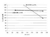
ところで、図4に示すように、旋回内側のリム外れは、セクションハイトSHが115mm以上のタイヤで発生しやすいことが確認されている。図4に示すグラフは、タイヤ幅を225mmにしてタイヤ断面高さSHを変更したランフラットラジアルタイヤを用いて、セクションハイトSHに対するリム外れ指標を調べたものであり、リム外れ指標の数値が大きいほど、リム外れしにくいことを示している。この図4によれば、セクションハイトSHが115mmより低いタイヤの場合は、タイヤの旋回外側の方がリム外れし易くなっており、セクションハイトSHが115mm以上のタイヤの場合は、タイヤの旋回内側の方がリム外れし易くなっている。この結果から、セクションハイトSHが115mm以上のタイヤでは、旋回内側のリム外れを抑制することが重要であることが分かる。なお、セクションハイトに特に上限はないが、例えば155mm以下である。 By the way, as shown in FIG. 4, it has been confirmed that the rim disengagement inside the turning is likely to occur in a tire having a section height SH of 115 mm or more. The graph shown in FIG. 4 is obtained by examining the rim detachment index with respect to the section height SH using a run-flat radial tire in which the tire width is 225 mm and the tire section height SH is changed, and the numerical value of the rim detachment index is large. It shows that it is hard to come off the rim. According to FIG. 4, in the case of a tire having a section height SH lower than 115 mm, the rim is more easily removed from the rim, and in the case of a tire having a section height SH of 115 mm or more, the inside of the tire is turned. It is easier to remove the rim. From this result, it can be seen that it is important to suppress rim disengagement inside the turn for tires having a section height SH of 115 mm or more. The section height is not particularly limited, but is, for example, 155 mm or less.
ここで、図1に示されるように、本実施形態のタイヤ10では、サイド補強ゴム24と最大幅のベルトプライ16Aとのタイヤ幅方向に沿った重複幅PをセクションハイトSHの20%以上の長さにしていることから、バックリング現象の起点となるトレッド端部近傍の剛性が高められて、トレッド部20のショルダー部が曲がりにくくなる。このため、ランフラット走行時のタイヤ10にSA(スリップアングル)が付与された場合であっても、図2に示されるように、タイヤサイド部22がタイヤ10の内側に折れ曲がることがない。これにより、ランフラット走行時にタイヤサイド部22にバックリング現象が発生するのを抑制できる。結果、ランフラット走行時の耐リム外れ性を向上させることができる。
Here, as shown in FIG. 1, in the
また、タイヤ10では、サイド補強ゴム24の上端部24Bをタイヤ幅方向最外側の周方向溝21Aよりもタイヤ幅方向外側に位置させている。言い換えると、タイヤ幅方向最外側の周方向溝21Aのタイヤ径方向内側にサイド補強ゴム24を配置しない構成としている。ここで、ランフラット走行時のタイヤ10にSA(スリップアングル)が付与された場合、トレッド部20の厚みが薄く、剛性が低くなる周方向溝21Aの溝底21ABを起点としてトレッド部20がタイヤ幅方向に折れ曲がることが確認されている。このため、サイド補強ゴム24の上端部24Bをタイヤ幅方向最外側の周方向溝21Aのタイヤ幅方向外側に配置することで、トレッド部20が周方向溝21Aの溝底21ABを起点として折れ曲がったとしても、このトレッド部20の折れ曲がりにともなう引張入力がサイド補強ゴム24に作用するのが抑制される。これにより、ランフラット走行時におけるサイド補強ゴム24の耐久性が向上するため、長期に亘ってタイヤサイド部22にバックリング現象が発生するのを抑制できる。
特に、本実施形態のタイヤ10では、タイヤ幅方向断面において、サイド補強ゴム24の上端部24Bを周方向溝21Aの溝底21ABと溝壁21AWとの交点からタイヤ幅方向に沿ってトレッド半幅HDの3%以上離間した位置に配置していることから、トレッド部20が周方向溝21Aの溝底21ABを起点として折れ曲がったとしても、サイド補強ゴム24にトレッド部20の折れ曲がりにともなう引張入力が作用するのが効果的に抑制される。
Further, in the
In particular, in the
さらに、サイド補強ゴム24の上端部24Bをタイヤ幅方向最外側の周方向溝21Aのタイヤ幅方向外側に配置することで、タイヤ10の重量増加を抑制することができる。
Furthermore, the weight increase of the
また、重複幅PをセクションハイトSHの22%〜27%の範囲内の長さに設定することで、上記バックリング現象の発生を抑制する効果と、上記重量増加を抑制する効果のバランスをとることができる。 Further, by setting the overlap width P to a length within the range of 22% to 27% of the section height SH, the effect of suppressing the occurrence of the buckling phenomenon and the effect of suppressing the weight increase are balanced. be able to.
また、サイド補強ゴム24の下端部24Aをビードフィラー28に重ねているので、タイヤサイド部22の剛性が増してランフラット走行時の耐久性を向上できる。さらに、ビードフィラー28の端部28Aをタイヤ10の最大幅位置よりもタイヤ径方向内側に設けているので、タイヤサイド部22の剛性が高くなり過ぎない。
Further, since the
また、図1の中点Qにおけるサイド補強ゴム24の厚みGBをサイド補強ゴム24の最大厚みGAの50%以下の厚みとしているので、中点Qにおけるカーカス14からサイド補強ゴム24の内面までの距離が短くなり、このサイド補強ゴム24の内面に作用する引張応力を低下させることができる。これにより、仮に、タイヤサイド部22にバックリング現象が発生しても、サイド補強ゴム24が破損するのを抑制できる。
Further, since the thickness GB of the
以上のように、セクションハイトSHが115mm以上のタイヤ10であっても、本実施形態のタイヤ10は、重複幅PをセクションハイトSHの20%以上の長さとすることで、タイヤサイド部22にバックリング現象が発生するのを抑制できる。
また、重複幅PをセクションハイトSHの22%〜27%の範囲内の長さとした場合には、タイヤサイド部22にバックリング現象が発生するのを抑制しつつ、タイヤ10の重量増加を抑制することができる。
As described above, even if the
Further, when the overlap width P is set to a length within the range of 22% to 27% of the section height SH, the occurrence of a buckling phenomenon in the
また、タイヤ10では、トレッド部20のタイヤ赤道CLからトレッド半幅HDの50%〜60%の範囲内に周方向溝21Aを形成していることから、トレッド部20の周方向溝21Aと接地端Tとの間の部分の剛性が確保される。これにより、ランフラット走行時のタイヤ10にSA(スリップアングル)が付与された場合のトレッド部20のタイヤ幅方向の折れ曲がりを抑制できる。
In the
また、サイド補強ゴム24の厚みGCを、カーカス14の最大幅位置におけるサイド補強ゴム24の厚み(本実施形態では、最大厚みGA)の70%以上の厚みに設定していることから、バックリング現象の起点となるトレッド端部近傍の剛性が高められて、トレッド部20のショルダー部がさらに曲がりにくくなる。これにより、ランフラット走行時にタイヤサイド部22にバックリング現象が発生するのを効果的に抑制できる。
Further, since the thickness GC of the
なお、本実施形態では、タイヤ幅方向両側のサイド補強ゴム24と最大幅のベルトプライ16Aとの重複幅Pをそれぞれ20%以上の長さとしているが、本発明はこの構成に限定されない。例えば、タイヤ装着方向内側のサイド補強ゴム24と最大幅のベルトプライ16Aとの重複幅Pを20%以上の長さとする構成としてもよい。リム外れは、パンクしたタイヤ10が旋回外側にある場合に、遠心力で発生するモーメントのため旋回外側のタイヤの垂直荷重が増加するため、タイヤ装着方向内側で発生しやすい。このため、上記対策によってリム外れを抑制することができる。
In the present embodiment, the overlap width P between the
(試験例)
本発明に係るランフラットラジアルタイヤの効果を確かめるために、以下の実施例1〜3のランフラットラジアルタイヤと、本発明に含まれない比較例1、2のランフラットラジアルタイヤを用意して以下の試験を実施した。
(Test example)
In order to confirm the effects of the run-flat radial tire according to the present invention, the following run-flat radial tires of Examples 1 to 3 and the run-flat radial tires of Comparative Examples 1 and 2 not included in the present invention were prepared. The test was conducted.
まず、試験に用いた実施例1、2のランフラットラジアルタイヤ及び比較例1〜3のランフラットラジアルタイヤについて説明する。試験に用いたランフラットラジアルタイヤのサイズは、何れも225/60R16である。また、実施例1、2及び比較例1〜3のランフラットラジアルタイヤは、本実施形態のタイヤ10と同じ構造を採用しており、重複幅P及び間隔Sの値がそれぞれ異なるタイヤである。
First, the run flat radial tires of Examples 1 and 2 and the run flat radial tires of Comparative Examples 1 to 3 used in the test will be described. The size of the run-flat radial tire used for the test is 225 / 60R16. Further, the run-flat radial tires of Examples 1 and 2 and Comparative Examples 1 to 3 adopt the same structure as the
・比較例1のランフラットラジアルタイヤは、サイド補強ゴムと最大幅のベルトプライとのタイヤ幅方向に沿った重複幅PをセクションハイトSHの15%の長さとしたタイヤである。また、比較例1では、トレッド半幅HDに対する間隔Sの割合を18.4%としている。
・比較例2のランフラットラジアルタイヤは、サイド補強ゴムと最大幅のベルトプライとのタイヤ幅方向に沿った重複幅PをセクションハイトSHの27.8%の長さとしたタイヤである。また、比較例2では、トレッド半幅HDに対する間隔Sの割合を0%、すなわち、間隔Sを0mmとしている。
・比較例3のランフラットラジアルタイヤは、重複幅PをセクションハイトSHの30%の長さとしたタイヤである。また、比較例3では、トレッド半幅HDに対する間隔Sの割合を−3%、すなわち、サイド補強ゴムがタイヤ幅方向最外側の周方向溝の溝底のタイヤ径方向内側に配置されたタイヤである。
・実施例1、2のランフラットラジアルタイヤの各重複幅P及び各間隔Sに関しては、表1に示す通りである。
The run-flat radial tire of Comparative Example 1 is a tire in which the overlapping width P along the tire width direction between the side reinforcing rubber and the maximum width belt ply is 15% of the section height SH. In Comparative Example 1, the ratio of the spacing S to the tread half width HD is 18.4%.
The run-flat radial tire of Comparative Example 2 is a tire in which the overlap width P along the tire width direction between the side reinforcing rubber and the maximum width belt ply is 27.8% of the section height SH. In Comparative Example 2, the ratio of the spacing S to the tread half width HD is 0%, that is, the spacing S is 0 mm.
The run-flat radial tire of Comparative Example 3 is a tire having an overlap width P that is 30% of the section height SH. Further, in Comparative Example 3, the ratio of the spacing S to the tread half width HD is −3%, that is, a tire in which the side reinforcing rubber is disposed on the inner side in the tire radial direction of the groove bottom of the outermost circumferential groove in the tire width direction. .
-About each overlap width P and each space | interval S of the run-flat radial tire of Example 1, 2, it is as showing in Table 1. FIG.
試験では、まず、供試タイヤをJATMA規格の標準リムに組み付け、空気を充填せずに(内圧を0kPaにして)車両に装着し、20km/hの速度で5kmの距離を慣らし走行した。その後、所定の速度で曲率半径が25mの旋回路に進入して、この旋回路の1/3周の位置で停止することを2回連続で実施した(Jターン試験)。ビード部がリムから外れていないときは、旋回加速度を上げて再度実施した。
ここで、比較例1のビード部がリムから外れたときの旋回加速度を基準値(100)として、実施例1〜3の各ビード部がリムから外れたときの旋回加速度を表1の「リム外れ指標」の欄に指数で表した。「リム外れ指標」は、ビード部がリムから外れたときの旋回加速度を指数で表したものであり、大きいほど良好な結果を示している。また、各供試タイヤの重量を測定し、比較例1の重量を基準値(100)として、実施例1〜3及び比較例の各タイヤの重量を表1の「重量指標」の欄に指数で表した。「重量指標」は、小さいほど重量が小さいことを示している。なお、表1における「最大幅のベルトプライの半幅HW」とは、最大幅のベルトプライの幅Wの半分の幅(W/2)を指す。
In the test, first, a test tire was assembled on a standard rim of JATMA standard, mounted on a vehicle without filling with air (with an internal pressure of 0 kPa), and conditioned for a distance of 5 km at a speed of 20 km / h. After that, entering a turning circuit having a radius of curvature of 25 m at a predetermined speed and stopping at a position of 1/3 turn of this turning circuit was performed twice in succession (J-turn test). When the bead portion did not come off the rim, the turning acceleration was increased and the operation was repeated.
Here, with reference to the turning acceleration when the bead portion of Comparative Example 1 is removed from the rim as a reference value (100), the turning acceleration when each bead portion of Examples 1 to 3 is removed from the rim is shown in Table 1 Expressed as an index in the column of “Outlier Index”. The “rim removal index” is an index that represents the turning acceleration when the bead part is removed from the rim, and the larger the value, the better the result. Further, the weight of each test tire was measured, and the weight of each of the tires of Examples 1 to 3 and the comparative example was indexed in the “weight index” column of Table 1 with the weight of Comparative Example 1 as the reference value (100). Expressed in The “weight index” indicates that the smaller the weight, the smaller the weight. The “half width HW of the maximum width belt ply” in Table 1 refers to a half width (W / 2) of the width W of the maximum width belt ply.

表1に示されるように、重複幅Pが大きくなるほど、リム外れ指標が良好な結果となるのが確認された。これは、重複幅Pが大きくなることで、トレッド端部近傍の剛性が高められ、タイヤサイド部が曲がりにくくなっているためと思われる。
一方、トレッド半幅HDに対する間隔Sの割合が7.1%を下回って0%に近づくほど、重複幅Pが大きくなっても、リム外れ指標の変動が小さくなることが確認された。これは、サイド補強ゴムをタイヤ幅方向最外側の周方向溝のタイヤ径方向内側に配置してもトレッド端部近傍の剛性への寄与が低いことを意味すると思われる。
As shown in Table 1, it was confirmed that the larger the overlap width P, the better the rim detachment index. This seems to be because the rigidity in the vicinity of the tread edge is increased and the tire side portion is difficult to bend due to the increase in the overlapping width P.
On the other hand, it was confirmed that as the ratio of the spacing S to the tread half-width HD is less than 7.1% and approaches 0%, the fluctuation of the rim detachment index becomes small even when the overlap width P increases. This seems to mean that even if the side reinforcing rubber is disposed on the inner side in the tire radial direction of the outermost circumferential groove in the tire width direction, the contribution to the rigidity in the vicinity of the tread end portion is low.
10 ランフラットラジアルタイヤ
12 ビード部
14 カーカス
16 傾斜ベルト層
16A ベルトプライ(最大幅のベルトプライ)
20 トレッド部
21 周方向溝
21A 周方向溝(タイヤ幅方向最外側の周方向溝)
21AB 溝底
21AW 溝壁
22 タイヤサイド部
24 サイド補強ゴム(サイド補強層)
24A 下端部(トレッド部側の端部)
SH セクションハイト(タイヤ断面高さ)
HD トレッド半幅
10 Run-flat
20
21AB Groove bottom
24A Lower end (end on tread side)
SH section height (tire cross section height)
HD tread half width
Claims (3)
前記カーカスのタイヤ径方向外側に設けられ、タイヤ周方向に対して傾斜する方向に延びるコードを備える少なくとも1枚のベルトプライによって構成された傾斜ベルト層と、
前記傾斜ベルト層のタイヤ径方向外側に設けられ、踏面にタイヤ周方向に延びる周方向溝が複数形成されたトレッド部と、
前記ビード部と前記トレッド部とを連結するタイヤサイド部に設けられ、前記カーカスの内面に沿って前記ビード部側から前記トレッド部側へ延びて最大幅の前記ベルトプライと重なり、前記最大幅のベルトプライとのタイヤ幅方向に沿った重複幅がタイヤ断面高さの20%以上の長さとされ、前記トレッド部側の端部がタイヤ幅方向最外側の前記周方向溝の溝底よりもタイヤ幅方向外側に配置されたサイド補強層と、
を有するランフラットラジアルタイヤ。 A carcass straddling between a pair of bead parts;
An inclined belt layer formed of at least one belt ply provided with a cord provided on the outer side in the tire radial direction of the carcass and extending in a direction inclined with respect to the tire circumferential direction;
A tread portion provided on the outer side in the tire radial direction of the inclined belt layer, and a plurality of circumferential grooves extending in the tire circumferential direction are formed on the tread;
Provided in a tire side portion that connects the bead portion and the tread portion, extends from the bead portion side to the tread portion side along the inner surface of the carcass and overlaps the belt ply of the maximum width, The overlap width along the tire width direction with the belt ply is 20% or more of the tire cross-section height, and the end on the tread portion side is more tire than the groove bottom of the circumferential groove on the outermost side in the tire width direction. A side reinforcing layer disposed on the outside in the width direction;
Run-flat radial tire having
Priority Applications (5)
| Application Number | Priority Date | Filing Date | Title |
|---|---|---|---|
| JP2014026752A JP2015151019A (en) | 2014-02-14 | 2014-02-14 | run-flat radial tire |
| CN201480075424.2A CN105980174B (en) | 2014-02-14 | 2014-12-12 | Run-flat radial |
| US15/117,451 US20160368328A1 (en) | 2014-02-14 | 2014-12-12 | Run-flat radial tire |
| EP14882453.5A EP3106324B1 (en) | 2014-02-14 | 2014-12-12 | Run-flat radial tire |
| PCT/JP2014/083048 WO2015122092A1 (en) | 2014-02-14 | 2014-12-12 | Run flat radial tire |
Applications Claiming Priority (1)
| Application Number | Priority Date | Filing Date | Title |
|---|---|---|---|
| JP2014026752A JP2015151019A (en) | 2014-02-14 | 2014-02-14 | run-flat radial tire |
Publications (1)
| Publication Number | Publication Date |
|---|---|
| JP2015151019A true JP2015151019A (en) | 2015-08-24 |
Family
ID=53799847
Family Applications (1)
| Application Number | Title | Priority Date | Filing Date |
|---|---|---|---|
| JP2014026752A Pending JP2015151019A (en) | 2014-02-14 | 2014-02-14 | run-flat radial tire |
Country Status (5)
| Country | Link |
|---|---|
| US (1) | US20160368328A1 (en) |
| EP (1) | EP3106324B1 (en) |
| JP (1) | JP2015151019A (en) |
| CN (1) | CN105980174B (en) |
| WO (1) | WO2015122092A1 (en) |
Cited By (1)
| Publication number | Priority date | Publication date | Assignee | Title |
|---|---|---|---|---|
| JP2017144976A (en) * | 2016-02-19 | 2017-08-24 | 株式会社ブリヂストン | Run flat tire |
Families Citing this family (5)
| Publication number | Priority date | Publication date | Assignee | Title |
|---|---|---|---|---|
| JP5536259B1 (en) * | 2013-06-13 | 2014-07-02 | 株式会社ブリヂストン | Run flat tire |
| JP6454471B2 (en) * | 2014-02-03 | 2019-01-16 | 株式会社ブリヂストン | Run-flat radial tire |
| JP6707863B2 (en) * | 2016-01-08 | 2020-06-10 | 住友ゴム工業株式会社 | Pneumatic tire |
| JP7105182B2 (en) * | 2018-12-26 | 2022-07-22 | 株式会社ブリヂストン | run flat tires |
| JP2020104621A (en) * | 2018-12-26 | 2020-07-09 | 株式会社ブリヂストン | Run-flat tire |
Citations (2)
| Publication number | Priority date | Publication date | Assignee | Title |
|---|---|---|---|---|
| JP2004017668A (en) * | 2002-06-12 | 2004-01-22 | Bridgestone Corp | Runflat tire |
| JP2005119384A (en) * | 2003-10-15 | 2005-05-12 | Bridgestone Corp | Run flat tire |
Family Cites Families (8)
| Publication number | Priority date | Publication date | Assignee | Title |
|---|---|---|---|---|
| JPH11227424A (en) * | 1998-02-18 | 1999-08-24 | Bridgestone Corp | Pneumatic safety tire |
| JP4073606B2 (en) * | 2000-05-17 | 2008-04-09 | 住友ゴム工業株式会社 | Pneumatic tire |
| JP4148696B2 (en) * | 2002-04-24 | 2008-09-10 | 横浜ゴム株式会社 | Pneumatic tire |
| JP4653651B2 (en) * | 2005-12-13 | 2011-03-16 | 住友ゴム工業株式会社 | Run flat tire |
| JP4880990B2 (en) * | 2005-12-13 | 2012-02-22 | 住友ゴム工業株式会社 | Run flat tire |
| JP5149780B2 (en) * | 2007-12-18 | 2013-02-20 | 住友ゴム工業株式会社 | Rubber composition for topping of case and / or breaker used for run-flat tire and run-flat tire using the same |
| JP5962481B2 (en) * | 2012-02-08 | 2016-08-03 | 横浜ゴム株式会社 | Pneumatic tire |
| JP6301105B2 (en) * | 2013-10-28 | 2018-03-28 | 株式会社ブリヂストン | Run-flat radial tire |
-
2014
- 2014-02-14 JP JP2014026752A patent/JP2015151019A/en active Pending
- 2014-12-12 EP EP14882453.5A patent/EP3106324B1/en not_active Not-in-force
- 2014-12-12 CN CN201480075424.2A patent/CN105980174B/en not_active Expired - Fee Related
- 2014-12-12 WO PCT/JP2014/083048 patent/WO2015122092A1/en active Application Filing
- 2014-12-12 US US15/117,451 patent/US20160368328A1/en not_active Abandoned
Patent Citations (2)
| Publication number | Priority date | Publication date | Assignee | Title |
|---|---|---|---|---|
| JP2004017668A (en) * | 2002-06-12 | 2004-01-22 | Bridgestone Corp | Runflat tire |
| JP2005119384A (en) * | 2003-10-15 | 2005-05-12 | Bridgestone Corp | Run flat tire |
Cited By (1)
| Publication number | Priority date | Publication date | Assignee | Title |
|---|---|---|---|---|
| JP2017144976A (en) * | 2016-02-19 | 2017-08-24 | 株式会社ブリヂストン | Run flat tire |
Also Published As
| Publication number | Publication date |
|---|---|
| EP3106324A4 (en) | 2017-02-22 |
| CN105980174A (en) | 2016-09-28 |
| EP3106324B1 (en) | 2019-06-26 |
| WO2015122092A1 (en) | 2015-08-20 |
| EP3106324A1 (en) | 2016-12-21 |
| US20160368328A1 (en) | 2016-12-22 |
| CN105980174B (en) | 2018-06-12 |
Similar Documents
| Publication | Publication Date | Title |
|---|---|---|
| WO2015122092A1 (en) | Run flat radial tire | |
| JP6454472B2 (en) | Run-flat radial tire | |
| JP6454471B2 (en) | Run-flat radial tire | |
| JP6377390B2 (en) | Run-flat radial tire | |
| JP6317130B2 (en) | Run flat tire | |
| JP6525505B2 (en) | Run flat tire | |
| JP6301105B2 (en) | Run-flat radial tire | |
| JP6411059B2 (en) | Side-reinforced run-flat radial tires for passenger cars | |
| JP6347979B2 (en) | Side-reinforced run-flat radial tire | |
| WO2014199756A1 (en) | Run-flat tire | |
| JP6347978B2 (en) | Run flat tire | |
| JP6162023B2 (en) | Run-flat radial tire | |
| JP6324740B2 (en) | Run flat tire | |
| JP2015147474A (en) | run-flat radial tire | |
| JP6268037B2 (en) | Run-flat radial tire | |
| JP6274815B2 (en) | Run-flat radial tire | |
| JP2015231762A (en) | Run-flat radial tire | |
| WO2021095884A1 (en) | Run-flat tire | |
| JP6075954B2 (en) | Pneumatic radial tire | |
| JP2018034742A (en) | Tire for two-wheeled vehicle |
Legal Events
| Date | Code | Title | Description |
|---|---|---|---|
| A621 | Written request for application examination |
Free format text: JAPANESE INTERMEDIATE CODE: A621 Effective date: 20161216 |
|
| A131 | Notification of reasons for refusal |
Free format text: JAPANESE INTERMEDIATE CODE: A131 Effective date: 20170926 |
|
| A521 | Request for written amendment filed |
Free format text: JAPANESE INTERMEDIATE CODE: A523 Effective date: 20171122 |
|
| A131 | Notification of reasons for refusal |
Free format text: JAPANESE INTERMEDIATE CODE: A131 Effective date: 20180417 |
|
| A521 | Request for written amendment filed |
Free format text: JAPANESE INTERMEDIATE CODE: A523 Effective date: 20180618 |
|
| A02 | Decision of refusal |
Free format text: JAPANESE INTERMEDIATE CODE: A02 Effective date: 20181204 |