WO2015114995A1 - Cystourethroscope for prostate biopsy and treatment tool - Google Patents
Cystourethroscope for prostate biopsy and treatment tool Download PDFInfo
- Publication number
- WO2015114995A1 WO2015114995A1 PCT/JP2014/083950 JP2014083950W WO2015114995A1 WO 2015114995 A1 WO2015114995 A1 WO 2015114995A1 JP 2014083950 W JP2014083950 W JP 2014083950W WO 2015114995 A1 WO2015114995 A1 WO 2015114995A1
- Authority
- WO
- WIPO (PCT)
- Prior art keywords
- treatment instrument
- cystourethroscope
- insertion portion
- shape
- opening
- Prior art date
Links
Images


Classifications
-
- A—HUMAN NECESSITIES
- A61—MEDICAL OR VETERINARY SCIENCE; HYGIENE
- A61B—DIAGNOSIS; SURGERY; IDENTIFICATION
- A61B10/00—Other methods or instruments for diagnosis, e.g. instruments for taking a cell sample, for biopsy, for vaccination diagnosis; Sex determination; Ovulation-period determination; Throat striking implements
- A61B10/02—Instruments for taking cell samples or for biopsy
- A61B10/04—Endoscopic instruments
-
- A—HUMAN NECESSITIES
- A61—MEDICAL OR VETERINARY SCIENCE; HYGIENE
- A61B—DIAGNOSIS; SURGERY; IDENTIFICATION
- A61B1/00—Instruments for performing medical examinations of the interior of cavities or tubes of the body by visual or photographical inspection, e.g. endoscopes; Illuminating arrangements therefor
- A61B1/00002—Operational features of endoscopes
- A61B1/00011—Operational features of endoscopes characterised by signal transmission
- A61B1/00013—Operational features of endoscopes characterised by signal transmission using optical means
-
- A—HUMAN NECESSITIES
- A61—MEDICAL OR VETERINARY SCIENCE; HYGIENE
- A61B—DIAGNOSIS; SURGERY; IDENTIFICATION
- A61B1/00—Instruments for performing medical examinations of the interior of cavities or tubes of the body by visual or photographical inspection, e.g. endoscopes; Illuminating arrangements therefor
- A61B1/00064—Constructional details of the endoscope body
- A61B1/00071—Insertion part of the endoscope body
-
- A—HUMAN NECESSITIES
- A61—MEDICAL OR VETERINARY SCIENCE; HYGIENE
- A61B—DIAGNOSIS; SURGERY; IDENTIFICATION
- A61B1/00—Instruments for performing medical examinations of the interior of cavities or tubes of the body by visual or photographical inspection, e.g. endoscopes; Illuminating arrangements therefor
- A61B1/012—Instruments for performing medical examinations of the interior of cavities or tubes of the body by visual or photographical inspection, e.g. endoscopes; Illuminating arrangements therefor characterised by internal passages or accessories therefor
- A61B1/018—Instruments for performing medical examinations of the interior of cavities or tubes of the body by visual or photographical inspection, e.g. endoscopes; Illuminating arrangements therefor characterised by internal passages or accessories therefor for receiving instruments
-
- A—HUMAN NECESSITIES
- A61—MEDICAL OR VETERINARY SCIENCE; HYGIENE
- A61B—DIAGNOSIS; SURGERY; IDENTIFICATION
- A61B1/00—Instruments for performing medical examinations of the interior of cavities or tubes of the body by visual or photographical inspection, e.g. endoscopes; Illuminating arrangements therefor
- A61B1/06—Instruments for performing medical examinations of the interior of cavities or tubes of the body by visual or photographical inspection, e.g. endoscopes; Illuminating arrangements therefor with illuminating arrangements
- A61B1/07—Instruments for performing medical examinations of the interior of cavities or tubes of the body by visual or photographical inspection, e.g. endoscopes; Illuminating arrangements therefor with illuminating arrangements using light-conductive means, e.g. optical fibres
-
- A—HUMAN NECESSITIES
- A61—MEDICAL OR VETERINARY SCIENCE; HYGIENE
- A61B—DIAGNOSIS; SURGERY; IDENTIFICATION
- A61B1/00—Instruments for performing medical examinations of the interior of cavities or tubes of the body by visual or photographical inspection, e.g. endoscopes; Illuminating arrangements therefor
- A61B1/303—Instruments for performing medical examinations of the interior of cavities or tubes of the body by visual or photographical inspection, e.g. endoscopes; Illuminating arrangements therefor for the vagina, i.e. vaginoscopes
-
- A—HUMAN NECESSITIES
- A61—MEDICAL OR VETERINARY SCIENCE; HYGIENE
- A61B—DIAGNOSIS; SURGERY; IDENTIFICATION
- A61B1/00—Instruments for performing medical examinations of the interior of cavities or tubes of the body by visual or photographical inspection, e.g. endoscopes; Illuminating arrangements therefor
- A61B1/307—Instruments for performing medical examinations of the interior of cavities or tubes of the body by visual or photographical inspection, e.g. endoscopes; Illuminating arrangements therefor for the urinary organs, e.g. urethroscopes, cystoscopes
-
- A—HUMAN NECESSITIES
- A61—MEDICAL OR VETERINARY SCIENCE; HYGIENE
- A61B—DIAGNOSIS; SURGERY; IDENTIFICATION
- A61B1/00—Instruments for performing medical examinations of the interior of cavities or tubes of the body by visual or photographical inspection, e.g. endoscopes; Illuminating arrangements therefor
- A61B1/31—Instruments for performing medical examinations of the interior of cavities or tubes of the body by visual or photographical inspection, e.g. endoscopes; Illuminating arrangements therefor for the rectum, e.g. proctoscopes, sigmoidoscopes, colonoscopes
-
- A—HUMAN NECESSITIES
- A61—MEDICAL OR VETERINARY SCIENCE; HYGIENE
- A61B—DIAGNOSIS; SURGERY; IDENTIFICATION
- A61B10/00—Other methods or instruments for diagnosis, e.g. instruments for taking a cell sample, for biopsy, for vaccination diagnosis; Sex determination; Ovulation-period determination; Throat striking implements
- A61B10/02—Instruments for taking cell samples or for biopsy
- A61B10/0233—Pointed or sharp biopsy instruments
- A61B10/0266—Pointed or sharp biopsy instruments means for severing sample
- A61B10/0275—Pointed or sharp biopsy instruments means for severing sample with sample notch, e.g. on the side of inner stylet
-
- A—HUMAN NECESSITIES
- A61—MEDICAL OR VETERINARY SCIENCE; HYGIENE
- A61B—DIAGNOSIS; SURGERY; IDENTIFICATION
- A61B8/00—Diagnosis using ultrasonic, sonic or infrasonic waves
- A61B8/12—Diagnosis using ultrasonic, sonic or infrasonic waves in body cavities or body tracts, e.g. by using catheters
-
- A—HUMAN NECESSITIES
- A61—MEDICAL OR VETERINARY SCIENCE; HYGIENE
- A61B—DIAGNOSIS; SURGERY; IDENTIFICATION
- A61B1/00—Instruments for performing medical examinations of the interior of cavities or tubes of the body by visual or photographical inspection, e.g. endoscopes; Illuminating arrangements therefor
- A61B1/04—Instruments for performing medical examinations of the interior of cavities or tubes of the body by visual or photographical inspection, e.g. endoscopes; Illuminating arrangements therefor combined with photographic or television appliances
- A61B1/05—Instruments for performing medical examinations of the interior of cavities or tubes of the body by visual or photographical inspection, e.g. endoscopes; Illuminating arrangements therefor combined with photographic or television appliances characterised by the image sensor, e.g. camera, being in the distal end portion
-
- A—HUMAN NECESSITIES
- A61—MEDICAL OR VETERINARY SCIENCE; HYGIENE
- A61B—DIAGNOSIS; SURGERY; IDENTIFICATION
- A61B17/00—Surgical instruments, devices or methods, e.g. tourniquets
- A61B2017/00681—Aspects not otherwise provided for
- A61B2017/00738—Aspects not otherwise provided for part of the tool being offset with respect to a main axis, e.g. for better view for the surgeon
Definitions
- the present invention relates to a cystourethroscope for prostate biopsy having a treatment instrument insertion channel that opens to an insertion section that can be inserted into a subject, and a treatment instrument that can be inserted into the treatment instrument insertion channel.
- a technique for causing the treatment tool to reach the prostate via the urethra is disclosed in, for example, Japanese Patent Application Laid-Open No. 2001-37775.
- a treatment instrument inserted into the human body through the urethra it is possible to perform a prostate biopsy to collect prostate tissue for diagnosis of prostate cancer.
- the urethra passes through the approximate center of the prostate, when collecting prostate tissue with a treatment tool inserted into the urethra, it is necessary to project the treatment tool in a direction crossing the urethra. . In order to improve the accuracy of the diagnosis, it is preferable to perform a biopsy over a wide area of the prostate.
- the present invention has been made in view of the above-described points, and an object thereof is to provide a cystourethroscope for prostate biopsy and a treatment tool that can easily perform a prostate biopsy via the urethra.
- a cystourethroscope for prostate biopsy has an insertion portion that can be inserted into a subject and is curved with a predetermined curvature in a state where no external force is applied, and a linear central axis.
- a gripping portion connected to intersect the insertion portion so that the central axis is located in a distal end cross section of the insertion portion, and a distal end portion extending in the convex direction of the curve from the distal end cross section
- the treatment tool according to one aspect of the present invention is a treatment tool that can be inserted at least partially into the treatment tool insertion channel of the cystourethroscope for prostate biopsy, and is a portion that can be inserted into the treatment tool insertion channel. However, it is configured to maintain a curved shape along the curve when no external force is applied.
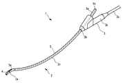
- the cystourethroscope 1 for prostate biopsy is an instrument used by being inserted into the urethra of a human body.
- the cystourethroscope for prostate biopsy is simply referred to as a cystourethroscope.
- the cystourethroscope 1 is used when performing at least one of observation and treatment of the prostate and bladder via the urethra.
- the cystourethroscope 1 of the present embodiment is, for example, an instrument that is inserted into the urethra and used when performing prostate biopsy of a human body that is a subject.
- the cystourethroscope 1 is configured so that a treatment tool 20 to be described later for collecting prostate tissue can be guided from outside the body to the prostate via the urethra. Collecting prostate tissue via the urethra is called transurethral biopsy.
- the cystourethroscope 1 of the present embodiment includes, as an example, an observation unit 4 that can capture at least one of an ultrasonic tomographic image and an optical image in a state of being inserted into the subject, and can observe the inside of the subject. It is configured.
- the cystourethroscope 1 of the present embodiment has a so-called rigid endoscope in which the insertion portion 2 that can be inserted into the urethra is configured to maintain a predetermined shape in a natural state that does not receive external force. is doing.
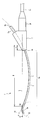
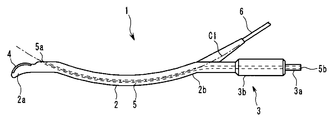
- the cystourethroscope 1 of the present embodiment includes an elongated insertion portion 2 configured to be insertable into the urethra, and a grip portion 3 connected to a proximal end portion 2 b of the insertion portion 2. And an observation section 4 disposed at the distal end 2a of the insertion section 2 and a treatment instrument insertion channel 5 configured to allow the treatment instrument 20 to be inserted therethrough.
- the insertion portion 2 is an elongated portion having a predetermined length and has a cross-sectional shape that can be inserted into the urethra.
- the cross-sectional shape of the insertion portion 2 may be any shape that can be smoothly rotated around the central axis in the urethra, and is, for example, a circular shape, an elliptical shape, or an oval shape. Moreover, the cross-sectional shape and cross-sectional area of the insertion part 2 may be changing on the way.
- An observation unit 4 is disposed at the distal end 2 a of the insertion unit 2.
- the length of the insertion part 2 is not specifically limited.
- the insertion portion 2 is provided with a curved portion 2c that is curved into a predetermined shape. The shape of the insertion portion 2 including the curved portion 2c will be described later.
- the grip part 3 is a part fixed to the proximal end 2b of the insertion part 2, and is a part for the user of the cystourethroscope 1 to grip when using it.
- the grasping portion 3 is provided with a treatment instrument insertion base 3a in which a second opening 5b of a treatment instrument insertion channel 5 described later is opened.
- the grip portion 3 is provided with a substantially columnar shaft portion 3b extending in the proximal direction.
- the shaft portion 3b has a substantially cylindrical shape in the illustrated embodiment, but the shape of the shaft portion 3b may be a quadrangular prism, an octagonal column, or the like.
- the shaft-shaped part 3 b is arranged in a state of being fixed with respect to the insertion part 2. The arrangement of the shaft portion 3b will be described later.
- a cable portion 3c through which an electric cable 6 and the like connected to the observation portion 4 described later is inserted extends from the grip portion 3.
- a connector portion configured to be connectable to an ultrasonic observation device or a video processor which is an external device (not shown) is provided at the end of the cable portion 3c.
- the cable part 3c is arrange
- the treatment instrument insertion channel 5 is a conduit disposed inside the cystourethroscope 1, and both ends open to the outside of the cystourethroscope 1.
- the treatment instrument insertion channel 5 has one end opened at the distal end portion 2 a of the insertion portion 2 or in the vicinity of the distal end portion 2 a, and the other end opened at the grasping portion 3.
- the treatment instrument insertion channel 5 is a duct having an inner diameter through which at least a part of the treatment instrument 20 can be inserted, and includes a first opening 5a provided in the insertion section 2 of the cystourethroscope 1 and a grasping section. 3 is in communication with the second opening 5b provided in the third opening 5b.
- the treatment instrument 20 inserted into the opening 5 b of the grip part 3 passes through the treatment instrument insertion channel 5 and protrudes from the opening 5 a of the insertion part 2.
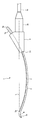
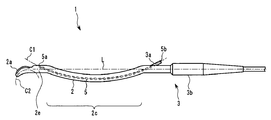
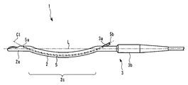
- the insertion portion 2 has a curved portion 5c configured to maintain a curved shape along a predetermined curve C1 in a state where no external force is applied.
- the bending portion 5c is provided in a region extending from the proximal end 2b of the insertion portion 2 to the vicinity of the first opening 5a.
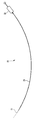
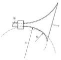
- the curved portion 2c is a predetermined curve C1 passing through the first opening 5a and the second opening 5b on a predetermined plane P (shown in FIG. 3) passing through the first opening 5a and the second opening 5b. Curved along (shown in FIG. 5).
- the shape of the curve C1 is not particularly limited, but an arc having a constant curvature radius is preferable.
- the shape of the curve C1 may be, for example, an elliptical curve, a hyperbola, a parabola, or the like with a changing radius of curvature.
- the curve C1 is an arc having a substantially constant value with a radius of curvature of approximately 100 mm to 600 mm.
- the radius of curvature of the curve C1 is set such that a projection angle A (shown in FIG. 5) of a treatment tool 20 that projects from the first opening 5a with respect to a straight line L (described later) is 15 to 45 degrees. ing.
- the distal end portion 2a which is a region closer to the distal end than the bending portion 2c of the insertion portion 2, has a shape that curves in a direction opposite to the bending direction of the bending portion 2c, or a linear shape. In the case where the distal end portion 2a is curved, it can be said that the distal end portion 2a is curved toward the convex direction of the curved portion 2c.
- the tip 2a of the present embodiment is along a curve C2 that curves in a direction opposite to the curve C1 on a predetermined plane P that passes through the first opening 5a and the second opening 5b. It is curved.
- the shape of the curve C2 is not particularly limited, and may be a circular arc with a constant curvature radius, or a shape with a changing curvature radius such as an elliptic curve, a hyperbola, or a parabola.
- the curve C2 is a circular arc having a radius of curvature smaller than that of the curve C1 and having a value of about 20 mm to 40 mm.
- the insertion portion 2 has rigidity to maintain the shape described above in a state where no external force is applied.
- the insertion portion 2 includes the curve C1 that is convex toward a predetermined direction on the predetermined plane P that passes through the first opening 5a and the second opening 5b, and the convex direction of the curve C1. Is an S-shape that is curved along a curve C2 that is convex in the opposite direction and that has an inflection part in the middle.
- connection part 2e which has a linear center axis
- the connection part 2e which has a linear center axis
- tip part 2a of the insertion part 2 may be linear.
- the insertion portion 2 has a bending portion between the distal end portion 2c and the bending portion 2c. It is the same as the form.
- the first opening 5a is disposed in the vicinity of the distal end of the bending portion 2c or in the vicinity of the proximal end of the distal end portion 2a.
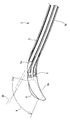
- the first opening 5 a is disposed in the vicinity of the inflection portion of the insertion portion 2. Therefore, as shown in FIG. 4, the treatment instrument 20 that is inserted into the treatment instrument insertion channel 5 and protrudes from the first opening 5 a protrudes in a direction away from the distal end portion of the insertion section 2 along the plane P.
- the 1st opening part 5a should just be opened to the position where the treatment tool 20 which protrudes from the said 1st opening part 5a enters into the observation range of the observation part 4.
- the first opening 5 a may be provided in the bending portion 2 c that curves along the curve C 1 of the insertion portion 2, or may be provided in the distal end portion 2 a of the insertion portion 2.
- the linear connection part 2e is provided between the curved part 2c and the front-end
- the treatment instrument insertion channel 5 is a conduit that is inserted into the bending portion 2c of the insertion portion 2 and communicates with the first opening 5a and the second opening 5b.
- the curved shape of the treatment instrument insertion channel 5 does not have to be positioned as the curved shape of the bending portion 2c.
- the electric cable 6 connected to the observation unit 4 can be run in parallel with the treatment instrument insertion channel 5.
- the treatment instrument insertion channel 5 is curved along the curve C1 on the plane P passing through the first opening 5a and the second opening 5b, similarly to the bending portion 2c. Yes.
- the shaft-shaped portion 3 b extends in the proximal direction of the cystourethroscope 1 along the cross-section of the distal end of the insertion portion 2, in other words, along the straight line L passing through the vicinity of the inflection portion of the insertion portion 2. It is arranged like this.
- the straight line L coincides with or is parallel to the central axis of the linear connection portion 2 e of the insertion portion 2.
- the straight line L is preferably coincident with or parallel to the central axis of the linear distal end portion 2 a of the insertion portion 2.
- the length of the part delimited by the curve C1 of the straight line L indicated by the symbol B in FIG. 5 is preferably 180 to 215 mm.
- the present invention is not limited to this length.
- the present invention can be applied to a cystourethroscope having a longer insertion portion, and the length of the portion indicated by the symbol B in that case is applicable.
- An example is 260 to 295 mm.
- symbol B is 0 to 15 mm.
- the observation unit 4 is disposed at the distal end portion 2 a of the insertion unit 2.
- the observation unit 4 of the present embodiment is an ultrasonic observation unit that includes a plurality of ultrasonic transducers and is configured to be able to transmit and receive ultrasonic waves.
- the observation unit 4 of the present embodiment has a form called a so-called convex scanning type, and is configured to be able to capture an ultrasonic tomographic image of a subject.
- the observation unit 4 includes a plurality of ultrasonic transducers arranged in an arc shape. By driving each ultrasonic transducer at a predetermined timing, as shown in FIG. It is possible to scan the ultrasonic beam in a substantially fan shape along P.
- a piezoelectric element such as piezoelectric ceramic, an electrostrictive element, an ultrasonic transducer (MUT) using a micromachine technique, or the like can be applied.
- the observation unit 4 is disposed at a position where the treatment tool 20 protruding from the first opening 5a can be accommodated within the observation range. Specifically, the observation unit 4 can scan an ultrasonic beam toward the radially outer side of the curved tip 2a, and the first opening 5a is included in the scanning range R (shown in FIG. 4). At least a part of the treatment tool 20 protruding from is inserted.
- the observation unit 4 is configured to be electrically connectable to an ultrasonic observation apparatus, which is an external device (not shown), via the insertion unit 2 and an electric cable 6 inserted into the cable 3c.
- the observation unit 4 is controlled by an ultrasonic observation apparatus connected via an electric cable 6.
- the observation unit 4 may be configured to be able to capture an optical image in the subject.
- the observation unit 4 includes, for example, an objective lens and an image sensor, and an electric cable electrically connected to the image sensor is used. It is arranged in the insertion part 2.
- the observation unit 4 may be configured to transmit an optical image by an optical fiber disposed in the insertion unit 2.
- an illumination device such as an optical fiber or LED for transmitting illumination light is disposed in the insertion unit 2.
- the observation unit 4 may include both an ultrasonic observation unit configured to be able to transmit and receive ultrasonic waves and an optical observation unit configured to be able to capture an optical image.
- the cystourethroscope 1 includes an ultrasonic observation unit configured to transmit and receive ultrasonic waves as the observation unit 4, and an endoscope configured to be able to capture an optical image is inserted into the treatment instrument insertion channel 5.
- the endoscope configured to be able to capture an optical image may be a rigid endoscope or a flexible endoscope.
- the cystourethroscope 1 includes an optical observation unit configured to capture an optical image as the observation unit 4, and an ultrasonic endoscope configured to be able to transmit and receive ultrasonic waves to the treatment instrument insertion channel 5. It may be configured to perform both ultrasonic observation and optical observation by being inserted.
- the ultrasonic endoscope configured to be able to transmit and receive ultrasonic waves may be a rigid endoscope or a flexible endoscope.
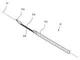
- the treatment instrument 20 includes an insertion portion 21 that is a portion that can be inserted into the treatment instrument insertion channel 5 of the cystourethroscope 1 described above, and an operation portion 22 provided at the proximal end of the insertion portion 21. Configured.
- the treatment tool 20 of the present embodiment is a biopsy needle configured to be able to collect prostate tissue by puncturing the prostate of the distal end portion of the insertion portion 21. Since the basic structure of the biopsy needle is known, detailed description thereof will be omitted.
- the insertion portion 21 has a needle-like inner needle 21a, a concave notch 21b provided at the tip of the inner needle 21a, and a tubular covering the periphery of the inner needle 21a. And an outer needle 21c that is movable relative to the inner needle 21a.
- the inner needle 21 a and the outer needle 21 c can be moved by operating a knob in the operation unit 22.
- the inner needle 21a and the outer needle 21c are both punctured before the site to be biopsied, and then only the inner needle 21a is punctured to the biopsy site up to the notch 21b. Thereafter, the outer needle 21c is moved to the inner needle and 21a is moved in the distal direction. By this operation, the tissue of a desired site in the prostate can be taken into the space of the notch 21b in the outer needle 21c.
- the treatment instrument 20 of the present embodiment is curved in the same manner as the curve C ⁇ b> 1 when the insertion portion 21, which is a part that can be inserted into the treatment instrument insertion channel 5, is not applied with an external force. It is comprised so that a shape may be maintained. That is, the insertion portion 21 of the treatment instrument 20 of the present embodiment has a substantially arc shape that is curved with substantially the same radius of curvature as the treatment instrument insertion channel 5 of the cystourethroscope 1. It should be noted that the radius of curvature of the insertion portion 21 does not need to completely coincide with the radius of curvature of the curve C1, and may be a value that is approximately approximate.
- the insertion portion 21 has a curved shape, the insertion portion 21 of the treatment instrument 20 can be easily and quickly inserted into the treatment instrument insertion channel 5 of the cystourethroscope 1 with a small force. Can do.
- the insertion part 21 in order to make the insertion part 21 appear clearly on the ultrasonic tomographic image, the insertion part 21 has a rough surface so as to scatter the irradiated ultrasonic waves as shown in FIG.
- the ultrasonic scattering portion 21d is provided.
- the ultrasonic scattering part 21d is provided only on the outer peripheral part on the radially outer side of the insertion part 21 curved in a substantially arc shape. This is because the insertion portion 21 is curved in accordance with the curvature of the treatment instrument insertion channel 5, and therefore when the insertion portion 21 protrudes from the first opening 5 a, the insertion portion 21 must be radially outside of the insertion portion 21. This is because the outer peripheral part faces the observation part 4.
- the cost required for manufacturing can be reduced by narrowing the range where the ultrasonic scattering part 21d is provided.
- the ultrasonic scattering unit 21d is provided only on the inner needle 21a.
- the ultrasonic scattering unit 21d may be provided only on the outer needle 21b, or the inner needle 21a and the outer needle 21a. It may be provided on both needles 21b.
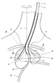
- FIG. 10 is a schematic diagram showing a state in which the cystoureteroscope 1 is inserted into the urethra 30 of the human body until the distal end portion 2a and the first opening 5a of the insertion portion 2 reach a site where the prostate 32 exists.
- the distal end portion 2 a and the first opening 5 a of the insertion portion 2 are located on the back side (bladder side) from the urethral sphincter 31. Yes.
- whether or not the cystourethroscope 1 has been inserted to the position shown in FIG. 10 is determined based on whether it is an ultrasonic tomographic image or optical image captured by the observation unit 4 or an endoscope inserted through the treatment instrument insertion port. This is confirmed using an optical image obtained by a mirror.
- the treatment instrument insertion channel 5 communicating with the first opening 5a and the distal end portion 2a which is a portion closer to the distal end than the first opening 5a of the insertion portion 2 are curved in opposite directions. For this reason, as shown in FIG. 11, the insertion portion 21 of the treatment instrument 20 protruding from the first opening 5 a protrudes in a direction away from the urethra 30. The protrusion operation of the treatment instrument 20 is performed while confirming an ultrasonic tomographic image captured by the observation unit 4.
- the insertion portion 2 is inserted into the urethra so that the first opening 5a is located in the region where the prostate 32 is present, the treatment tool 20 inserted through the treatment instrument insertion channel 5 is obtained.
- the urinary tract is projected at an angle to the urethra. Therefore, according to the cystourethroscope 1 and the treatment instrument 20 of the present embodiment, the insertion portion 21 of the treatment instrument 20 can be easily punctured into the marginal region 32a of the prostate 32 without being limited to the urethral sphincter 31. Can do.
- the marginal area 32a of the prostate 32 is generally a cancerous part. That is, according to the present embodiment, a prostate biopsy via the urethra can be easily performed.
- the fact that the operation of the cystourethroscope 1 and the treatment instrument 20 is less likely to be restricted by the urethral sphincter 31, means that the stimulation to the urethral sphincter 31 is reduced, that is, pain or discomfort when performing a procedure. The patient's distress will be reduced. For this reason, in this embodiment, the anesthesia performed at the time of a prostate biopsy can be made shallow, and a prostate biopsy can be completed quickly.
- the shaft-like portion 3b of the grip portion 3 extends along a straight line L passing through the vicinity of the first opening 5a. Therefore, in the state where the insertion portion 2 is inserted into the urethra 30 as shown in FIG. 10, the user grasps the shaft-shaped portion 3b and rotates the cystourethroscope 1 about the substantially central axis of the shaft-shaped portion 3b. When moved, the insertion portion 2 rotates around the straight line L without giving a large stimulus to the urethral sphincter 31.
- FIG. 12 shows a state where the shaft portion 3b is rotated 180 degrees from the state of FIG.
- the protruding direction of the treatment instrument 20 protruding from the first opening 5a also rotates around the straight line L. Therefore, the treatment instrument 20 can be punctured in a region along the conical surface with the straight line L as a substantially central axis.
- a prostate biopsy can be performed easily and quickly without causing great pain even if there are a plurality of locations from which tissue is collected. be able to. It is preferable to increase the number of locations from which tissues are collected because the accuracy of diagnosis can be improved.
- the stimulation given to the urethral sphincter 31 is small when changing the location where the tissue is collected, the anesthesia performed at the time of prostate biopsy can be made shallow, and the prostate biopsy can be completed quickly.
- the treatment instrument 20 has a shape in which the insertion portion 21 is curved in the same manner as the curved shape of the treatment instrument insertion channel 5, but the insertion portion 21 of the treatment instrument 20 has the treatment instrument insertion channel 5.
- the insertion portion 21 of the treatment instrument 20 may have a substantially straight shape like a conventionally used biopsy needle. In this case, the force required to insert the insertion portion 21 of the treatment instrument 20 through the treatment instrument insertion channel 5 increases, but the other effects are the same as those of the above-described embodiment.
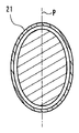
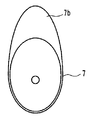
- FIG. 13 shows a cross-sectional shape of the insertion portion 21.
- the insertion portion 21 has a substantially elliptical shape or a substantially elliptical shape having a major axis in a direction substantially orthogonal to the plane P including the curve C1 along which the insertion portion 21 is aligned. It may be a flat shape.
- the area of the outer peripheral surface facing the radially outer side of the curved insertion portion 21 increases. For this reason, in the ultrasonic tomographic image imaged by the observation part 4, the insertion part 21 is drawn more clearly.
- FIG. 14 shows a cross-sectional shape of the insertion portion 21.
- the insertion portion 21 is a flattened shape such as a substantially elliptical shape or a substantially elliptical shape having a major axis in a direction substantially parallel to the plane P including the curve C ⁇ b> 1 along which the insertion portion 21 extends. It may be a simple shape.
- the strength of maintaining the insertion portion 21 in a curved shape can be improved.
- the insertion portion 2 has a curved shape in the vicinity of the proximal end portion 2b.
- the vicinity of the proximal end portion 2b of the insertion portion 2 has a linear shape. It may be.
- the treatment tool penetration channel 5 is arrange
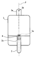
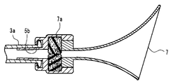
- the cystourethroscope 1 of the present embodiment is characterized in that the treatment instrument insertion port 7, the irrigation inlet 9, and the cock 8 are disposed in the treatment instrument insertion base 3 a. Different from the embodiment.
- the treatment instrument insertion port 7 is a funnel-shaped member that decreases in diameter toward the second opening 5b.
- the treatment instrument insertion port 7 is a member having a shape that widens the second opening 5b toward the proximal end side.
- the treatment instrument insertion port 7 can be attached to and detached from the treatment instrument insertion hole 3a by, for example, a screw mechanism called a luer lock.
- the irrigation water inlet 9 is an opening for pouring the perfusate into the treatment instrument insertion channel 5 and communicates with the treatment instrument insertion channel 5.
- the irrigation water inlet 9 can be opened and closed by a cock 8.
- the funnel-shaped treatment instrument insertion port 7 in the treatment instrument insertion base 3a by providing the funnel-shaped treatment instrument insertion port 7 in the treatment instrument insertion base 3a, the insertion of the insertion portion 21 of the treatment instrument 20 into the treatment instrument insertion channel 5 is facilitated.
- a sponge rubber 7a may be disposed in the treatment instrument insertion port 7 so as to close the second opening 5b.
- the sponge rubber 7a can be penetrated by the distal end of the insertion portion 21 of the treatment instrument 20.
- the sponge rubber 7a may be divided into two at the center as shown in FIG. 19 so that the insertion part 21 of the treatment instrument 20 can be easily penetrated.
- a configuration in which a cut or a through hole is formed in the sponge rubber 7a can be considered.
- the shape of the treatment instrument insertion port 7 may be a conical shape or a pyramid shape such as a triangular pyramid or a quadrangular pyramid. As shown in FIG. 17, the shape is not limited to a shape that linearly increases in diameter toward the opening direction, but as shown in FIG. 18, a shape in which the inclination of the inner wall surface with respect to the central axis increases toward the opening direction (inner The wall surface may be inwardly convex), or conversely, the bell shape may be smaller (inner wall surface is outwardly convex) with respect to the central axis toward the opening direction. May be.
- the curvature radius in the axial direction of the treatment instrument insertion port 7 is a shape along a curve, as shown in FIG. 20, the curvature radius may change in the middle.
- the curvature radius R1 of the wall surface of the treatment tool insertion port 7 near the treatment tool insertion hole 3 a is larger than the curvature radius R2 of the portion near the opening end of the treatment tool insertion port 7.
- the cross-sectional shape in the axial direction of the treatment instrument insertion port 7 may be a shape in which the direction of the unevenness of the inner wall surface is reversed halfway.
- the opening end of the treatment instrument insertion port 7 may have a shape cut by a plane substantially orthogonal to the central axis of the treatment instrument insertion hole 3a, or as shown in FIG. The shape may be cut by a plane that forms a predetermined angle with respect to the central axis of the treatment instrument insertion base 3a. Further, the opening end of the treatment instrument insertion port 7 may have a shape cut out by a curved surface as shown in FIG.
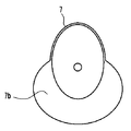
- the treatment instrument insertion port 7 of the present embodiment has a plate-like tongue piece portion 7b extending outward from the outer edge portion of the opening end.
- the planar shape of the tongue piece portion 7b of the present embodiment is an elliptical shape, but the planar shape of the tongue piece portion 7b is not limited to this, and may be a rectangle or a trapezoid. Also good.
- the treatment instrument 20 when the treatment instrument 20 is inserted into the treatment instrument insertion opening 7 by providing the treatment instrument insertion opening 7 with the tongue piece portion 7b extending outward from the opening end, the treatment instrument 20 is inserted. Even if the distal end of the treatment tool is disengaged from the opening of the treatment instrument insertion port 7, it is possible to prevent the distal end of the treatment tool 20 from touching the user's hand, the grip portion 3 or the like.
- the tongue 7b is provided with a wall 7c that surrounds the periphery and protrudes in the opening direction, the distal end of the treatment instrument 20 that hits the tongue 7b can be securely inserted into the opening. I can guide you.
- the tongue piece portion 7b is not limited to a shape extending in one direction from the outer edge portion of the opening end, and extends outward from all or a predetermined range around the opening of the treatment instrument insertion port 7. The shape to take out may be sufficient.
- the tongue piece 7b of the modification shown in FIGS. 25 and 26 has a shape extending outward from approximately a half of the periphery of the opening of the treatment instrument insertion port 7.
Abstract
Description
以下に、本発明の第2の実施形態を説明する。以下では第1の実施形態との相違点のみを説明するものとし、第1の実施形態と同様の構成要素については同一の符号を付し、その説明を適宜に省略するものとする。 (Second Embodiment)
The second embodiment of the present invention will be described below. Hereinafter, only differences from the first embodiment will be described, and the same components as those in the first embodiment are denoted by the same reference numerals, and description thereof will be omitted as appropriate.
以下に、本発明の第3の実施形態を説明する。以下では第2の実施形態との相違点のみを説明するものとし、第2の実施形態と同様の構成要素については同一の符号を付し、その説明を適宜に省略するものとする。 (Third embodiment)
The third embodiment of the present invention will be described below. Hereinafter, only differences from the second embodiment will be described, and the same components as those of the second embodiment are denoted by the same reference numerals, and description thereof will be omitted as appropriate.
Claims (5)
- 被検体に挿入可能であり、外力が加えられていない状態で所定の曲率で湾曲している挿入部と、
直線状の中心軸を有し、前記挿入部の先端断面内に前記中心軸が位置するように、前記挿入部と交差するように接続された把持部と、
前記先端断面から前記湾曲の凸方向に伸張している先端部と、
前記先端部に形成された観察部と、
前記挿入部の内部に形成され、挿通された処置具が前記観察部の観察範囲内に突出するよう開口している処置具挿通チャンネルと、
を含むことを特徴とする前立腺生検用膀胱尿道鏡。 An insertion portion that can be inserted into the subject and is curved with a predetermined curvature in a state where no external force is applied;
A gripping portion having a straight central axis and connected so as to intersect the insertion portion so that the central axis is located in a distal end cross section of the insertion portion;
A tip extending in the convex direction of the curve from the tip cross-section;
An observation part formed at the tip part;
A treatment instrument insertion channel formed inside the insertion section and opened so that the inserted treatment instrument projects into the observation range of the observation section;
A cystourethroscope for prostate biopsy characterized by comprising: - 前記挿入部の曲率は一定であることを特徴とする請求項1に記載の前立腺生検用膀胱尿道鏡。 The cystourethroscope for prostate biopsy according to claim 1, wherein the curvature of the insertion portion is constant.
- 前記観察部は、超音波を送受信する超音波送受部であることを特徴とする請求項1又は2に記載の前立腺生検用膀胱尿道鏡。 The cystourethroscope for prostate biopsy according to claim 1 or 2, wherein the observation unit is an ultrasonic transmission / reception unit that transmits / receives ultrasonic waves.
- 前記挿入部と、前記先端部との間に直線状の中心軸を有する接続部が配置されることを特徴とする請求項1から3のいずれか一項に記載の前立腺生検用膀胱尿道鏡。 The cystourethroscope for prostate biopsy according to any one of claims 1 to 3, wherein a connecting portion having a linear central axis is disposed between the insertion portion and the distal end portion. .
- 請求項1から4のいずれか一項に記載の前記前立腺生検用膀胱尿道鏡の前記処置具挿通チャンネルに少なくとも一部が挿通可能な処置具であって、
前記処置具挿通チャンネルに挿通可能な部位が、外力が加えられていない状態では、前記曲線に沿って湾曲した形状を維持するように構成されている
ことを特徴とする処置具。 A treatment instrument that can be inserted at least partially into the treatment instrument insertion channel of the cystourethroscope for prostate biopsy according to any one of claims 1 to 4,
The treatment tool is configured such that a portion that can be inserted into the treatment tool insertion channel is configured to maintain a curved shape along the curve when no external force is applied.
Priority Applications (4)
| Application Number | Priority Date | Filing Date | Title |
|---|---|---|---|
| JP2015527700A JP5885887B2 (en) | 2014-01-29 | 2014-12-22 | Rigid endoscope and treatment tool for prostate biopsy |
| CN201480067785.2A CN105813575B (en) | 2014-01-29 | 2014-12-22 | Prostate biopsy rigid scope and processing utensil |
| EP14880595.5A EP3100685B1 (en) | 2014-01-29 | 2014-12-22 | Rigid endoscope for prostate biopsy |
| US15/221,984 US9775589B2 (en) | 2014-01-29 | 2016-07-28 | Rigid endoscope for prostate biopsy and treatment instrument |
Applications Claiming Priority (2)
| Application Number | Priority Date | Filing Date | Title |
|---|---|---|---|
| JP2014014681 | 2014-01-29 | ||
| JP2014-014681 | 2014-01-29 |
Related Child Applications (1)
| Application Number | Title | Priority Date | Filing Date |
|---|---|---|---|
| US15/221,984 Continuation US9775589B2 (en) | 2014-01-29 | 2016-07-28 | Rigid endoscope for prostate biopsy and treatment instrument |
Publications (1)
| Publication Number | Publication Date |
|---|---|
| WO2015114995A1 true WO2015114995A1 (en) | 2015-08-06 |
Family
ID=53756587
Family Applications (1)
| Application Number | Title | Priority Date | Filing Date |
|---|---|---|---|
| PCT/JP2014/083950 WO2015114995A1 (en) | 2014-01-29 | 2014-12-22 | Cystourethroscope for prostate biopsy and treatment tool |
Country Status (5)
| Country | Link |
|---|---|
| US (1) | US9775589B2 (en) |
| EP (1) | EP3100685B1 (en) |
| JP (1) | JP5885887B2 (en) |
| CN (1) | CN105813575B (en) |
| WO (1) | WO2015114995A1 (en) |
Cited By (1)
| Publication number | Priority date | Publication date | Assignee | Title |
|---|---|---|---|---|
| WO2020100844A1 (en) * | 2018-11-15 | 2020-05-22 | ニプロ株式会社 | Lacrimal endoscope |
Citations (7)
| Publication number | Priority date | Publication date | Assignee | Title |
|---|---|---|---|---|
| JPH08336591A (en) * | 1995-06-13 | 1996-12-24 | Asahi Optical Co Ltd | Injection means for endoscope |
| JPH0938202A (en) * | 1995-08-04 | 1997-02-10 | Asahi Optical Co Ltd | Endoscopic injection instrument |
| JPH0984790A (en) * | 1995-09-20 | 1997-03-31 | Olympus Optical Co Ltd | Internal palpatory device |
| JPH10234653A (en) * | 1997-02-28 | 1998-09-08 | Olympus Optical Co Ltd | Endoscope |
| JP2001037775A (en) | 1999-07-26 | 2001-02-13 | Olympus Optical Co Ltd | Treatment device |
| JP2002306497A (en) * | 2001-04-18 | 2002-10-22 | Asahi Optical Co Ltd | Puncture device for endoscope |
| JP2014014681A (en) | 2012-07-11 | 2014-01-30 | Heraeus Dental Ab | Screw channel directing device for dental superstructure and method for manufacturing dental superstructure |
Family Cites Families (15)
| Publication number | Priority date | Publication date | Assignee | Title |
|---|---|---|---|---|
| US1453975A (en) * | 1919-10-18 | 1923-05-01 | Greenberg Geza | Urethroscope |
| JPH07227394A (en) * | 1994-02-21 | 1995-08-29 | Olympus Optical Co Ltd | Ultrasonic diagnostic and curing system |
| US5964740A (en) | 1996-07-09 | 1999-10-12 | Asahi Kogaku Kogyo Kabushiki Kaisha | Treatment accessory for an endoscope |
| US6929600B2 (en) * | 2001-07-24 | 2005-08-16 | Stephen D. Hill | Apparatus for intubation |
| EP4026486A1 (en) * | 2004-03-23 | 2022-07-13 | Boston Scientific Medical Device Limited | In-vivo visualization system |
| JP2005279128A (en) * | 2004-03-31 | 2005-10-13 | Fujinon Corp | Internal insertion type inspection apparatus |
| JP5042029B2 (en) * | 2005-10-18 | 2012-10-03 | オリンパス株式会社 | Endoscopic treatment tool |
| EP2335553A4 (en) * | 2009-06-01 | 2012-11-07 | Olympus Medical Systems Corp | Medical equipment system and method for calibrating medical instrument |
| US8608652B2 (en) * | 2009-11-05 | 2013-12-17 | Ethicon Endo-Surgery, Inc. | Vaginal entry surgical devices, kit, system, and method |
| US20110230711A1 (en) * | 2010-03-16 | 2011-09-22 | Kano Akihito | Endoscopic Surgical Instrument |
| JP2011200356A (en) * | 2010-03-25 | 2011-10-13 | Fujifilm Corp | Endoscope insertion auxiliary tool |
| US20120088356A1 (en) * | 2010-09-14 | 2012-04-12 | Applied Materials, Inc. | Integrated platform for in-situ doping and activation of substrates |
| EP2455133A1 (en) * | 2010-11-18 | 2012-05-23 | Koninklijke Philips Electronics N.V. | Catheter comprising capacitive micromachined ultrasonic transducers with an adjustable focus |
| EP2671513A4 (en) * | 2011-10-27 | 2015-05-20 | Olympus Medical Systems Corp | Ultrasonic observation device |
| JP5425354B1 (en) * | 2012-08-14 | 2014-02-26 | オリンパスメディカルシステムズ株式会社 | Endoscope |
-
2014
- 2014-12-22 JP JP2015527700A patent/JP5885887B2/en active Active
- 2014-12-22 EP EP14880595.5A patent/EP3100685B1/en not_active Not-in-force
- 2014-12-22 CN CN201480067785.2A patent/CN105813575B/en active Active
- 2014-12-22 WO PCT/JP2014/083950 patent/WO2015114995A1/en active Application Filing
-
2016
- 2016-07-28 US US15/221,984 patent/US9775589B2/en active Active
Patent Citations (7)
| Publication number | Priority date | Publication date | Assignee | Title |
|---|---|---|---|---|
| JPH08336591A (en) * | 1995-06-13 | 1996-12-24 | Asahi Optical Co Ltd | Injection means for endoscope |
| JPH0938202A (en) * | 1995-08-04 | 1997-02-10 | Asahi Optical Co Ltd | Endoscopic injection instrument |
| JPH0984790A (en) * | 1995-09-20 | 1997-03-31 | Olympus Optical Co Ltd | Internal palpatory device |
| JPH10234653A (en) * | 1997-02-28 | 1998-09-08 | Olympus Optical Co Ltd | Endoscope |
| JP2001037775A (en) | 1999-07-26 | 2001-02-13 | Olympus Optical Co Ltd | Treatment device |
| JP2002306497A (en) * | 2001-04-18 | 2002-10-22 | Asahi Optical Co Ltd | Puncture device for endoscope |
| JP2014014681A (en) | 2012-07-11 | 2014-01-30 | Heraeus Dental Ab | Screw channel directing device for dental superstructure and method for manufacturing dental superstructure |
Cited By (1)
| Publication number | Priority date | Publication date | Assignee | Title |
|---|---|---|---|---|
| WO2020100844A1 (en) * | 2018-11-15 | 2020-05-22 | ニプロ株式会社 | Lacrimal endoscope |
Also Published As
| Publication number | Publication date |
|---|---|
| EP3100685A1 (en) | 2016-12-07 |
| US9775589B2 (en) | 2017-10-03 |
| CN105813575A (en) | 2016-07-27 |
| US20160331359A1 (en) | 2016-11-17 |
| JP5885887B2 (en) | 2016-03-16 |
| JPWO2015114995A1 (en) | 2017-03-23 |
| EP3100685A4 (en) | 2018-03-14 |
| CN105813575B (en) | 2019-01-04 |
| EP3100685B1 (en) | 2019-10-30 |
Similar Documents
| Publication | Publication Date | Title |
|---|---|---|
| JP5678239B2 (en) | Ultrasound endoscope | |
| JP5407036B2 (en) | Treatment endoscope | |
| US7918785B2 (en) | Medical apparatus, treatment instrument for endoscope and endoscope apparatus | |
| JP5265823B1 (en) | Ultrasonic observation equipment | |
| JP5448637B2 (en) | Insertion path securing device | |
| JP5629043B1 (en) | Biopsy system | |
| JPH11276422A (en) | Ultrasonic endoscope | |
| JP2007289673A (en) | Treatment tool for endoscope | |
| WO2006106881A1 (en) | Endoscope | |
| WO2017061537A1 (en) | Ultrasonic endoscope | |
| WO2016042849A1 (en) | Biopsy system | |
| JP5885887B2 (en) | Rigid endoscope and treatment tool for prostate biopsy | |
| US20130331645A1 (en) | Endoscopic device and endoscope treatment system | |
| KR100881811B1 (en) | Endoscope, curve control assist member for endoscope and a set of bending operation knob | |
| JPH07194594A (en) | Treating tool inserting passage for in vivo inspecting device | |
| JPH01280446A (en) | Ultrasonic endoscope | |
| CN219645761U (en) | Ultrasonic endoscope and head end thereof | |
| JP4217485B2 (en) | Ultrasound endoscope | |
| JP4302292B2 (en) | Ultrasound endoscope | |
| JPH1085227A (en) | Guide device of medical instrument with flexible cord | |
| JP2010178860A (en) | Endoscope | |
| CN117224158A (en) | Ultrasonic probe, light source instrument and puncture guiding system | |
| JP2013233210A (en) | Insertion part-distal end structure of ultrasonic endoscope | |
| JP2013233272A (en) | Ultrasonic endoscope | |
| JP2010178862A (en) | Endoscope |
Legal Events
| Date | Code | Title | Description |
|---|---|---|---|
| ENP | Entry into the national phase |
Ref document number: 2015527700 Country of ref document: JP Kind code of ref document: A |
|
| 121 | Ep: the epo has been informed by wipo that ep was designated in this application |
Ref document number: 14880595 Country of ref document: EP Kind code of ref document: A1 |
|
| REEP | Request for entry into the european phase |
Ref document number: 2014880595 Country of ref document: EP |
|
| WWE | Wipo information: entry into national phase |
Ref document number: 2014880595 Country of ref document: EP |
|
| NENP | Non-entry into the national phase |
Ref country code: DE |