JP4217485B2 - Ultrasound endoscope - Google Patents
Ultrasound endoscope Download PDFInfo
- Publication number
- JP4217485B2 JP4217485B2 JP2003000619A JP2003000619A JP4217485B2 JP 4217485 B2 JP4217485 B2 JP 4217485B2 JP 2003000619 A JP2003000619 A JP 2003000619A JP 2003000619 A JP2003000619 A JP 2003000619A JP 4217485 B2 JP4217485 B2 JP 4217485B2
- Authority
- JP
- Japan
- Prior art keywords
- distal end
- ultrasonic
- hole
- holder
- endoscope
- Prior art date
- Legal status (The legal status is an assumption and is not a legal conclusion. Google has not performed a legal analysis and makes no representation as to the accuracy of the status listed.)
- Expired - Fee Related
Links
Images


Description
【0001】
【発明の属する技術分野】
本発明は、内視鏡挿入部の先端硬性部の先端側に、複数の圧電素子を配列して構成した超音波振動子を有するホルダーが配置される電子走査式の超音波内視鏡に関する。
【0002】
【従来の技術】
近年、体腔内に挿入可能な内視鏡挿入部の先端に超音波振動子を設け、内視鏡の処置具挿通用チャンネルを通して体腔内に処置具を導出して、病変部の組織を採取する等の診断や処置を行えるとともに、前記超音波振動子によって超音波断層画像を得られるようにした電子走査式或いは機械走査式の超音波内視鏡が実用化されている。
【0003】
前記電子走査式の超音波内視鏡においては、ハウジング(本実施形態ではホルダーと記載)に多数の圧電素子を整列配置させており、これら圧電素子から延出する素線(信号線)が超音波装置に接続されている。したがって、この超音波装置によって前記圧電素子を適宜駆動させることによって所望の超音波画像を得られるようになっている。そして、前記ハウジングにできるだけ多くの圧電素子を配列することによって優れた分解能の超音波画像を得られる。
【0004】
例えば、特開2001−170054号公報に開示されている超音波内視鏡では、超音波振動子部を構成する振動子アレイを配列したハウジングを、先端硬性部に形成した振動子用透孔に配置する構成であった。
【0005】
この超音波内視鏡では、例えば図10(a)、(b)に示すように先端硬性部100の先端部に、バルーン取付け用溝101及び図示しないバルーン内に超音波伝達媒体を供給するための注入口102を形成した注液路103を有する、環状部104が設けられていた。
【特許文献1】
特開2001−170054号公報(頁3、図3(b))
【発明が解決しようとする課題】
しかしながら、挿入可能部位の拡大や患者の苦痛低減等の目的で超音波内視鏡の挿入部の細径化が求められており、前記図10(a)、(b)に示した構成の超音波内視鏡では、この構成のままで細径化を図ったとき、先端硬性部の振動子用透孔に挿入配置されるハウジングの基端部を構成するパイプ部分の厚みが薄肉になって所望の強度が得られず、細径化を断念せざるを得なかった。
【0006】
本発明は上記事情に鑑みてなされたものであり、先端硬性部に挿入配置される超音波振動子部のパイプ部分の強度を低下させることなく、細径化を図った超音波内視鏡を提供することを目的にしている。
【0007】
【課題を解決するための手段】
本発明の一態様による超音波内視鏡は、内視鏡挿入部の先端部を構成する先端硬性部に形成したホルダ配置孔に挿入配置されるホルダーに、複数の圧電素子を配列して構成した超音波振動子を設けた超音波内視鏡において、
前記ホルダーに前記超音波振動子を覆い包むバルーン内に液体を供給するバルーン用注液路を設け、前記ホルダーの外周所定位置に前記先端硬性部の先端面に対向してバルーン取り付け用の溝を形成する周方向凸部を設けている。
この構成で、先端硬性部の先端部に環状部を形成するために要していた肉部がホルダー側に設けられて、先端硬性部の細径化とホルダーの強度の維持が図れる。
【0009】
【発明の実施の形態】
以下、図面を参照して本発明の実施の形態を説明する。
図1ないし図7は本発明の第1実施形態に係り、図1は超音波内視鏡の概略構成を説明する図、図2は超音波振動子部の先端部分を説明する図、図3は超音波内視鏡の先端部分の内部構造を説明する断面図、図4は図3(a)のE−E線断面図、図5は図4のG−G線断面図、図6は図3(a)のF−F線断面図、図7は超音波振動子部の先端部分の他の構成を説明する図である。
【0010】
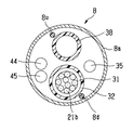
なお、図2(a)は超音波内視鏡の先端部分を説明する側面図、図2(b)は超音波内視鏡の先端部分を図2(a)の矢印A方向から見たときの図、図2(c)は超音波内視鏡の先端部分を図2(a)の矢印B方向から見たときの図、図3(a)は図2(b)のD−D線に沿った説明断面図、図3(b)は図2(a)のC−C線に沿った説明断面図である。
【0011】
図1に示すように本実施形態の超音波内視鏡1は、例えば気管に挿入される細長な挿入部2と、この挿入部2の基端に位置する操作部3と、この操作部3の側部から延出するユニバーサルコード4とで主に構成されており、前記操作部3の基端部には接眼部5が設けられている。
【0012】
前記ユニバーサルコード4の基端部には図示しない光源装置に接続される内視鏡コネクタ4aが設けられている。この内視鏡コネクタ4aからは図示しない超音波観測装置に超音波コネクタ6aを介して着脱自在に接続される超音波ケーブル6が延出している。
【0013】
前記挿入部2は、先端側から順に硬質な樹脂部材で形成した硬性部材7Aに傾斜面7aを有する先端硬性部7、この先端硬性部7の後端に位置する湾曲操作自在な湾曲部8、この湾曲部8の後端に位置して前記操作部3の先端部に至る細径かつ長尺で可撓性を有する可撓管部9を連設して構成されている。前記先端硬性部7の先端側には超音波を送受する複数の圧電素子を配列して構成した超音波振動子を備えた超音波振動子部20が設けられている。
【0014】
なお、前記硬性部材7Aの材質としては、耐薬品性や生体適合性が良好なポリスルフォンが用いられる。また、前記操作部3には前記湾曲部8を所望の方向に湾曲操作するためのアングルノブ11、体腔内に図示しない処置具挿通用チャンネルを介して導入される処置具の入り口となる処置具挿入口12等が設けられている。
【0015】
図2(a)ないし図2(c)に示すように前記先端硬性部7には観察光学系を構成する観察窓13と、照明光学系を構成する照明窓14と、処置具挿通用チャンネルの出口側開口部(以下、開口部と略記する)15と、後述する固定ピン(図4の符号41)が挿通配置されるピン孔16とが設けられている。なお、前記観察窓13及び照明窓14の両者を開口部15に対して一方の側にまとめて配置している。また、前記開口部15は一部分が前記傾斜面7aにかかるように形成されている。
【0016】
前記超音波振動子部20の長手方向中心軸は、観察光学系の観察視野及び照明光学系の照明範囲がこの超音波振動子部20によって大きく遮られることを防止するため、先端硬性部7の長手方向中心軸に対して下方に芯ずれさせて、前記観察窓13及び照明窓14を傾斜面7aの所定位置に配置させている。
【0017】
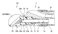
前記超音波振動子部20は、硬性部材7Aの先端面7bから突出するホルダー20Aを有している。このホルダー20Aは、図示しない数十個の圧電素子を例えば円弧状に配列して構成した超音波走査面21aを有する超音波振動子21が配設された振動子配置部22と、この振動子配置部22の基端面から突出して前記硬性部材7Aの先端面7bに形成されている振動子用透孔である後述するホルダ配置孔(図3の符号7c参照)に挿入配置されるパイプ部23とで主に構成されている。
【0018】
前記パイプ部23の振動子配置部側所定位置である先端側には全周に渡って突出した周状凸部24aが設けられている。また、この周状凸部24aの先端側面と前記振動子配置部22の基端面との間には後述する流体管路の先端側開口である注液口25aが形成されている。
【0019】
図3(a)及び図3(b)を参照して超音波振動子部20及び先端硬性部7の構成を説明する。
図に示すように前記ホルダー20Aのパイプ部23は、前記硬性部材7Aの先端面7bに開口を形成したホルダ配置孔7cに配置される。そして、このホルダ配置孔7cの所定位置に前記パイプ部23を配置することによって、この周状凸部24aの基端面側が前記先端面7bに対向して、バルーンを取り付けるための溝が構成される。
【0020】
前記ホルダ配置孔7cに挿通配置されるパイプ部23は、振動子配置部側である先端側を構成する大径管部23aと、基端側を構成してこの大径管部23aより小さく形成した小径管部23bとで構成されている。この小径管部23bの基端部には前記超音波振動子21を構成する各圧電素子から延出する複数の信号線21bをひとまとめにした超音波ケーブル31が挿通する絶縁チューブ32の先端部が連通固定されている。この絶縁チューブ32は、挿入部2内を挿通して操作部3まで延出している。
【0021】
前記パイプ部23を構成する大径管部23aには前記周状凸部24aの他に、この大径管部23aと前記ホルダ配置孔7cの後述する係入孔との間の水密を図るOリング33が配置される周溝24bが、所定位置に全周に渡って形成されている。
【0022】
また、前記大径管部23aには前記注液口25aに連通する流体管路25が形成されている。この流体管路25の基端側開口25bは、前記大径管部23aと小径管部23bとの段面(図3(b)参照)に形成されており、この基端側開口25bにはチューブ接続口金34が配設されている。このチューブ接続口金34には注液チューブ35の先端部が連通固定されている。
【0023】
一方、図に示すように前記先端硬性部7には前記ホルダ配置孔7c及び前記開口部15を有する処置具挿通用チャンネル孔17が形成されている。また、前記先端硬性部7の基端部には前記湾曲部8を構成する湾曲駒8aが接続固定されるとともに、この湾曲駒8a等を被覆する湾曲ゴム8bの先端部が糸巻き接着部8cによって一体的に固定されている。
【0024】
前記ホルダ配置孔7cは、内視鏡長手軸に対して略平行に形成されている。このホルダ配置孔7cは、先端側を形成して前記パイプ部23を構成する大径管部23aの基端側部が係入配置される係入孔7d及び、基端側を形成して、前記小径管部23bの外形寸法より所定寸法だけ大きく形成した遊嵌孔7eとで構成されている。
【0025】
前記遊嵌孔7e内には前記小径管部23b、絶縁チューブ32及び前記注液チューブ35が挿通配置され、前記係入孔7dには大径管部23aが配置される。つまり、ホルダ配置孔7cの所定位置に前記パイプ部23が配置されるとき、この大径管部23aの周溝24bに配置されているOリング33が前記係入孔7dの内周面に密着して水密を確保する状態になる。
【0026】
前記開口部15は、前記先端硬性部7の側面及び前記傾斜面7aに渡って形成されている。具体的には、前記開口部15の大部分を前記硬性部材7Aの側面に形成して、この開口部15の一部分を前記傾斜面7aに形成している。
このことによって、吸引状態のとき、硬性部材7Aの側面が体壁に密着状態になることが防止される。また、超音波ガイド下穿刺のときには、この開口部15から突出する例えば一点鎖線に示す穿刺針36の突出角度θ1を大きくして、この穿刺針36をできるだけ超音波振動子21の超音波走査面21aから遠く離れた観察部位への穿刺が可能になっている。
【0027】
前記処置具挿通用チャンネル孔17は内視鏡長手軸に対して傾いて形成されている。具体的に、前記処置具挿通用チャンネル孔17は、開口部15側を構成する先端側チャンネル孔17aと基端開口側を構成する基端側チャンネル孔17bとを有しており、前記先端側チャンネル孔17aの傾斜角度は前記突出角度θ1ができるだけ大きくなるように可能な限り大きく設定される。また、前記基端側チャンネル孔17bも所定量(θ2)だけ傾斜している。
【0028】
所定量傾斜した前記基端側チャンネル孔17bにはチューブ連結パイプ37を介して処置具挿通用チャンネルを構成する処置具挿通用チャンネルチューブ38が連通配置される。
【0029】
これらのことにより、この処置具挿通用チャンネルチューブ38内を導かれた穿刺針36は、基端側チャンネル孔17b内及び先端側チャンネル孔17a内をスムーズに移動して開口部15から突出する。
【0030】
前記超音波振動子部20を構成するパイプ部23は、前記先端硬性部7のホルダ配置孔7cに挿通され、大径管部23aと小径管部23bとの段面と係入孔7dと遊嵌孔7eとが当接した状態で、図4に示すように固定ピン41によって位置決めされる。このことによって、前記周状凸部24aと前記先端面7bとでバルーン取付け用の溝が形成される。また、前記超音波振動子部20の超音波走査面21aが所定方向を向いた状態になる。
【0031】
前記固定ピン41は、前記先端硬性部7に形成されたピン孔16に挿入配置され、接着剤42によって、この先端硬性部7に一体的に接着固定される。この接着状態とき、前記固定ピン41の両端部が先端硬性部7側に位置して、この固定ピン41の中央部分が前記大径管部23aに形成されている孔23c内に位置した状態になる。
【0032】
このことによって、先端硬性部7に配置させた超音波振動子部20の長手方向位置が変化することや、たとえ大径管部23aの断面形状を円形に形成した場合でもこの大径管部23aが係入孔7d内で回動移動して超音波走査面21aが位置ずれすることが防止される。ただし、大径管部23aの断面形状を非円形とした場合などは固定ピン41の一片端が先端硬性部7側に、他片端が大径管部23a内に位置してもよい。
【0033】
なお、前記先端硬性部7には前記ピン孔16より細径でこのピン孔16に連通する作業用透孔43が形成してある。この作業用透孔43を設けたことによって、予め接着剤42を塗布した状態のピン孔16に固定ピン41を挿入していくとき、余分な接着剤42をこの作業用透孔43に排除しながら前記固定ピン41をピン孔16の所定位置にスムーズに配置させられる。また、この接着剤42によって先端硬性部7に接着固定されている固定ピン41を取り外す際には、まず、この作業用透孔43及び前記ピン孔16に充填されている接着剤42を除去し、その後、図示しない棒部材を作業用透孔43に挿通配置させることにより、前記固定ピン41の叩き出しを行える。
【0034】
なお、符号44は前記観察光学系を構成する前記観察窓13に臨むイメージガイドであり、符号45は前記照明光学系を構成する前記照明窓14に臨むライトガイドである。
【0035】
図4及び図5に示すように前記硬性部材7Aに配置されているイメージガイド44及びライトガイド45は、内視鏡長手軸方向に対して所定量傾斜している。そして、この硬性部材7Aの基端下方側には、前記イメージガイド44及びライトガイド45の屈曲部を形成するための、屈曲部形成穴46が形成されている。この屈曲部形成穴46を設けたことによって、前記イメージガイド44及びライトガイド45をこの屈曲部形成穴46で余裕を持たせて屈曲させて、ファイバ折れが防止される。なお、実際には図4のA−A線の断面図にあってはイメージガイド44の一部しか示されないが、説明を明瞭にするためにイメージガイド44の先端付近を全体的に示した。
【0036】
このことによって、光を屈折させるための小型の光学プリズムを製作することなく、イメージガイド44及びライトガイド45を直接、硬性部材7Aに傾斜配置させて、傾斜面7aの所定位置に観察窓13及び照明窓14が配置される。
【0037】
なお、前記屈曲部形成穴46を加工する際に、硬性部材7Aの外表面に露出する切り欠き部が形成されてしまう場合がある。このときは、所定寸法に形成した蓋部材47を配置して前記切り欠き部を塞いだ状態にした後、前記湾曲駒8a及び湾曲ゴム8bを配置して接着部8cを設けて、前記切り欠き部による不具合の発生を防止する。
【0038】
図6に示すように前記湾曲部8を構成する湾曲駒8a内には、前記超音波振動子21から延出する複数の信号線21bが挿通する超音波ケーブル31を被覆する絶縁チューブ32、前記処置具挿通用チャンネル孔17に連通する処置具挿通用チャンネルチューブ38、前記観察窓13から延出するイメージガイド44、前記照明窓14から延出するライトガイド45及び前記チューブ接続口金34に連通する注液チューブ35等が挿通している。なお、符号8uは湾曲部を上方に湾曲させるための上方向湾曲ワイヤであり、8dは湾曲部を下方に湾曲させるための下方向湾曲ワイヤである。
【0039】
そして、本実施形態においては、前記絶縁チューブ32及び処置具挿通用チャンネルチューブ38の互いの中心が湾曲駒8aの中心近傍を通って一直線上に並ぶように配置し、この一直線上に配置した前記絶縁チューブ32及び処置具挿通用チャンネルチューブ38の両側に形成される空間にイメージガイド44及びライトガイド45と注液チューブ35を分けて配置している。このことによって、イメージガイド44及びライトガイド45と注液チューブ35とが離れた位置関係を保持して挿入部内に配置される。
【0040】
このように、超音波振動子部を構成するホルダーの大径管部に周状凸部及び流体管路を設ける一方、硬性部材の先端面にバルーン取付け用の溝及び注液路を有する凸部を設けることなく、前記ホルダーの管部が挿通配置されるホルダ配置孔を設け、このホルダ配置孔にホルダーを配置固定することによって、バルーンを取り付けるための溝及び流体の供給が可能な流体管路を有する超音波内視鏡を構成することができる。
【0041】
このことによって、硬性部材の先端面からバルーン取付け用の溝及び注液路を有する凸部がなくなって、硬性部材の細径化が実現される。
【0042】
また、超音波ケーブルを被覆する絶縁チューブ及び処置具挿通用チャンネルチューブを湾曲駒内に各中心が略一直線上に並ぶように配置することによって、挿入部の細径化を図ることができる。
【0043】
さらに、観察窓及び照明窓を前記処置具挿通用チャンネルの開口部の一方側に配置したことによって、処置具挿通用チャンネルの開口部から処置具を突出させたとき、この処置具によって照明窓から出射されている照明光が遮られて、観察部位が暗くなることを確実に防止することができる。
【0044】
又、照明窓に臨むイメージガイドファイバとバルーン用注液路とを、処置具挿通用チャンネルチューブ及び超音波ケーブルを挟んで配置したことによって、イメージガイドファイバ近傍にバルーン用注液路が位置することをなくして、イメージガイドファイバがバルーン用注液路を流れる流体によって急冷されて生じる不具合を確実に防止することができる。
【0045】
なお、本構成の超音波振動子部20を前記図10に示した太さ寸法の超音波内視鏡に適用すると、硬性部材7Aの先端面からバルーン取付け用の溝及び注液路を有する凸部がなくなって、図7に示すように大径管部23aの肉厚tを厚肉にして強度的に優れたホルダー20Aの構成が可能になる。
【0046】
図8及び図9は本発明の第2実施形態にかかり、図8は管部に設ける超音波ケーブルが挿通する透孔と流体管路との形成位置関係を説明する図、図9は絶縁チューブと注液チューブとの配置位置関係を説明する図である。
【0047】
本実施形態においては前記パイプ部23の大径管部23aに形成される超音波ケーブル31を図8に示すように挿通配置するためのケーブル用透孔の形成位置を前記大径管部23aの中心から位置ずれさせるとともに、流体管路の位置を23cからのケーブル用透孔までの距離に合わせて移動させている。
【0048】
このことによって、流体管路とケーブル用透孔との間隔が幅広になって、図9に示すように、チューブ接続口金34をストレート形状にして注液チューブ35を余裕を持って、このチューブ接続口金34に連通固定させられる。
【0049】
このように、管部に形成するケーブル用透孔及び流体管路の配置位置を適宜考慮することによって、使い勝手に優れたホルダーを構成することができる。
【0050】
なお、上述した実施形態においては、管部の断面形状を円形としてしているが、管部の断面形状は円形に限定されるものではなく、例えば、1つの弦部を有する略D字形や楕円形、或いは卵形等であってもよい。
【0051】
尚、本発明は、以上述べた実施形態のみに限定されるものではなく、発明の要旨を逸脱しない範囲で種々変形実施可能である。
【0052】
[付記]
以上詳述したような本発明の上記実施形態によれば、以下の如き構成を得ることができる。
【0053】
(1)内視鏡挿入部の先端部を構成する先端硬性部に形成されたホルダ配置孔に挿入配置されるホルダーに複数の圧電素子を配列して形成した超音波振動子を設けた超音波内視鏡において、
前記ホルダーに、前記超音波振動子を覆い包むバルーン内に液体を供給するバルーン用注液路を設けるとともに、前記ホルダーの外周面所定位置に前記先端硬性部の先端面に対向してバルーン取付け用の溝を形成する周方向凸部を設けた超音波内視鏡。
【0054】
(2)超音波振動子を備え、バルーン用注液路を設けたホルダーが着脱自在に配置される先端硬性部に、観察窓、照明窓及び処置具挿通用チャンネル開口部を設けた超音波内視鏡において、
前記処置具挿通用チャンネル開口部に連通する処置具挿通用チャンネルチューブ及び、前記超音波振動子から延出する超音波ケーブルを、先端硬性部の配置位置関係にあわせて内視鏡挿入部内に一列に配置した超音波内視鏡。
【0055】
(3)前記観察窓と照明窓との配置位置関係を、前記処置具挿通用チャンネル開口部の位置を考慮して設定した付記2に記載の超音波内視鏡。
【0056】
このことによって、処置具挿通用チャンネル開口部から例えば穿刺針を突出させたとき、この穿刺針によって照明窓から出射されている照明光が遮られて、観察窓でとらえる内視鏡像に穿刺針の影が映り込むこと不具合が防止される。
【0057】
(4)前記照明窓に臨むイメージガイドファイバ及びライトガイドファイバと、前記バルーン用注液路とを、前記処置具挿通用チャンネルチューブ及び超音波ケーブルを挟んで配置した付記2又は付記3に記載の超音波内視鏡。
【0058】
【発明の効果】
以上説明したように本発明によれば、先端硬性部に挿入配置される超音波振動子部のパイプ部分の強度を低下させることなく、細径化を図った超音波内視鏡を提供することができる。
【図面の簡単な説明】
【図1】図1ないし図7は本発明の第1実施形態に係り、図1は超音波内視鏡の概略構成を説明する図
【図2】超音波振動子部の先端部分を説明する図
【図3】超音波内視鏡の先端部分の内部構造を説明する断面図
【図4】図3(a)のA−A線断面図
【図5】図4のA−A線断面図
【図6】図3(a)のB−B線断面図
【図7】超音波振動子部の先端部分の他の構成を説明する図
【図8】図8及び図9は本発明の第2実施形態にかかり、図8は管部に設ける超音波ケーブルが挿通する透孔と流体管路との形成位置関係を説明する図
【図9】絶縁チューブと注液チューブとの配置位置関係を説明する図
【図10】先端硬性部の先端部に、バルーン取付け用溝及び超音波伝達媒体を供給するための注液路を有する凸部を設けた超音波内視鏡の構成を説明する図
【符号の説明】
1…超音波内視鏡
7…先端硬性部
7A…硬性部材
7b…先端面
7c…ホルダ配置孔
20…超音波振動子部
20A…ホルダー
23…パイプ部
23a…大径管部
24a…周状凸部
25…流体管路[0001]
BACKGROUND OF THE INVENTION
The present invention relates to an electronic scanning ultrasonic endoscope in which a holder having an ultrasonic transducer in which a plurality of piezoelectric elements are arranged is arranged on the distal end side of a distal end rigid portion of an endoscope insertion portion.
[0002]
[Prior art]
In recent years, an ultrasonic transducer is provided at the distal end of an endoscope insertion portion that can be inserted into a body cavity, and the treatment tool is led into the body cavity through the treatment tool insertion channel of the endoscope, and the tissue of the lesioned part is collected. In addition, an electronic scanning or mechanical scanning ultrasonic endoscope that can perform diagnosis and treatment such as the above and obtain an ultrasonic tomographic image by the ultrasonic transducer has been put into practical use.
[0003]
In the electronic scanning ultrasonic endoscope, a large number of piezoelectric elements are arranged in a housing (described as a holder in the present embodiment), and the wires (signal lines) extending from these piezoelectric elements are super-exposed. Connected to the sonic device. Therefore, a desired ultrasonic image can be obtained by appropriately driving the piezoelectric element by this ultrasonic apparatus. An ultrasonic image having excellent resolution can be obtained by arranging as many piezoelectric elements as possible in the housing.
[0004]
For example, in an ultrasonic endoscope disclosed in Japanese Patent Application Laid-Open No. 2001-170054, a housing in which a transducer array that constitutes an ultrasonic transducer section is arranged is provided in a vibrator through-hole formed in a distal end hard portion. It was a configuration to arrange.
[0005]
In this ultrasonic endoscope, for example, as shown in FIGS. 10A and 10B, an ultrasonic transmission medium is supplied to the distal end portion of the distal end
[Patent Document 1]
Japanese Patent Laying-Open No. 2001-170054 (
[Problems to be solved by the invention]
However, there has been a demand for reducing the diameter of the insertion portion of the ultrasonic endoscope for the purpose of, for example, expanding the insertable portion and reducing the patient's pain, and the superstructure of the configuration shown in FIGS. In the sonic endoscope, when the diameter is reduced with this configuration, the thickness of the pipe portion constituting the base end portion of the housing inserted and disposed in the vibrator through hole of the distal end rigid portion becomes thin. The desired strength could not be obtained, and the reduction in diameter had to be abandoned.
[0006]
The present invention has been made in view of the above circumstances, and an ultrasonic endoscope having a reduced diameter without reducing the strength of the pipe portion of the ultrasonic transducer portion inserted and disposed in the distal end rigid portion. The purpose is to provide.
[0007]
[Means for Solving the Problems]
An ultrasonic endoscope according to an aspect of the present invention is configured by arranging a plurality of piezoelectric elements in a holder that is inserted and arranged in a holder arrangement hole formed in a distal end rigid portion that constitutes a distal end portion of an endoscope insertion portion. In an ultrasonic endoscope provided with an ultrasonic transducer,
The holder is provided with a balloon injection path for supplying a liquid into a balloon covering the ultrasonic transducer, and a balloon mounting groove is formed at a predetermined position on the outer periphery of the holder so as to face the distal end surface of the distal end rigid portion. The circumferential convex part to form is provided.
With this configuration, the meat portion required for forming the annular portion at the distal end portion of the distal end rigid portion is provided on the holder side, so that the diameter of the distal end rigid portion can be reduced and the strength of the holder can be maintained.
[0009]
DETAILED DESCRIPTION OF THE INVENTION
Embodiments of the present invention will be described below with reference to the drawings.
1 to 7 relate to a first embodiment of the present invention, FIG. 1 is a diagram for explaining a schematic configuration of an ultrasonic endoscope, FIG. 2 is a diagram for explaining a tip portion of an ultrasonic transducer part, and FIG. Is a cross-sectional view for explaining the internal structure of the distal end portion of the ultrasonic endoscope, FIG. 4 is a cross-sectional view taken along the line EE of FIG. 3A, FIG. 5 is a cross-sectional view taken along the line GG of FIG. FIG. 3A is a cross-sectional view taken along the line FF in FIG. 3A, and FIG. 7 is a diagram illustrating another configuration of the tip portion of the ultrasonic transducer unit.
[0010]
2A is a side view for explaining the distal end portion of the ultrasonic endoscope, and FIG. 2B is a view when the distal end portion of the ultrasonic endoscope is viewed from the direction of arrow A in FIG. 2A. FIG. 2 (c) is a view when the distal end portion of the ultrasonic endoscope is viewed from the direction of arrow B in FIG. 2 (a), and FIG. 3 (a) is a DD line in FIG. 2 (b). FIG. 3B is an explanatory cross-sectional view taken along the line CC of FIG. 2A.
[0011]
As shown in FIG. 1, an
[0012]
An endoscope connector 4 a connected to a light source device (not shown) is provided at the base end portion of the
[0013]
The
[0014]
As the material of the
[0015]
As shown in FIGS. 2 (a) to 2 (c), the distal end
[0016]
The central axis in the longitudinal direction of the
[0017]
The
[0018]
A circumferential
[0019]
With reference to FIG. 3A and FIG. 3B, the configuration of the
As shown in the drawing, the
[0020]
The
[0021]
In addition to the circumferential
[0022]
Further, a
[0023]
On the other hand, as shown in the figure, the distal end
[0024]
The
[0025]
The small-diameter pipe portion 23b, the insulating
[0026]
The
This prevents the side surface of the
[0027]
The treatment instrument
[0028]
A treatment instrument
[0029]
For these reasons, the puncture needle 36 guided through the treatment instrument
[0030]
The
[0031]
The fixing
[0032]
As a result, even if the longitudinal position of the
[0033]
The distal end
[0034]
[0035]
As shown in FIGS. 4 and 5, the
[0036]
As a result, the
[0037]
When the bent
[0038]
As shown in FIG. 6, in the
[0039]
And in this embodiment, it arrange | positions so that the mutual center of the said
[0040]
Thus, while providing the circumferential convex part and the fluid conduit on the large-diameter pipe part of the holder constituting the ultrasonic transducer part, the convex part having the balloon mounting groove and the liquid injection path on the distal end surface of the rigid member Without providing a holder, a holder arrangement hole into which the pipe portion of the holder is inserted is arranged, and the holder is arranged and fixed in the holder arrangement hole, whereby a groove for attaching a balloon and a fluid conduit capable of supplying fluid Can be configured.
[0041]
This eliminates the convex portion having the balloon mounting groove and the liquid injection path from the distal end surface of the rigid member, thereby realizing a reduction in the diameter of the rigid member.
[0042]
Moreover, the diameter of the insertion portion can be reduced by arranging the insulating tube covering the ultrasonic cable and the treatment instrument insertion channel tube in the bending piece so that the respective centers are aligned in a substantially straight line.
[0043]
Furthermore, by arranging the observation window and the illumination window on one side of the opening of the treatment instrument insertion channel, when the treatment instrument protrudes from the opening of the treatment instrument insertion channel, the treatment instrument removes the illumination window from the illumination window. It can prevent reliably that the emitted illumination light is interrupted | blocked and an observation site | part becomes dark.
[0044]
In addition, by placing the image guide fiber facing the illumination window and the balloon injection path between the treatment instrument insertion channel tube and the ultrasonic cable, the balloon injection path is positioned near the image guide fiber. Therefore, it is possible to surely prevent a problem that occurs when the image guide fiber is rapidly cooled by the fluid flowing through the balloon injection channel.
[0045]
When the
[0046]
8 and 9 are related to a second embodiment of the present invention. FIG. 8 is a diagram for explaining the formation positional relationship between a through hole through which an ultrasonic cable provided in a pipe portion is inserted and a fluid conduit, and FIG. 9 is an insulating tube. It is a figure explaining the arrangement | positioning positional relationship with a liquid injection tube.
[0047]
In the present embodiment, the formation position of the cable through hole for inserting and arranging the
[0048]
As a result, the distance between the fluid conduit and the cable through-hole is widened, and as shown in FIG. 9, the
[0049]
As described above, a holder that is easy to use can be configured by appropriately considering the arrangement positions of the cable through holes and the fluid conduits formed in the pipe portion.
[0050]
In the above-described embodiment, the cross-sectional shape of the tube portion is circular. However, the cross-sectional shape of the tube portion is not limited to a circular shape. For example, a substantially D-shaped or elliptical shape having one chord portion. It may be a shape or an oval shape.
[0051]
The present invention is not limited to the above-described embodiments, and various modifications can be made without departing from the spirit of the invention.
[0052]
[Appendix]
According to the embodiment of the present invention as described above in detail, the following configuration can be obtained.
[0053]
(1) Ultrasound provided with an ultrasonic transducer formed by arranging a plurality of piezoelectric elements in a holder that is inserted and arranged in a holder arrangement hole formed in a distal end rigid portion constituting the distal end portion of the endoscope insertion portion In an endoscope,
The holder is provided with a balloon injection path for supplying a liquid into a balloon covering the ultrasonic transducer, and is attached to the balloon at a predetermined position on the outer peripheral surface of the holder so as to face the distal end surface of the distal rigid portion. An ultrasonic endoscope provided with a circumferential projection that forms a groove.
[0054]
(2) Ultrasound inside provided with an observation window, an illumination window, and a treatment instrument insertion channel opening at the distal end rigid portion provided with an ultrasonic vibrator and provided with a holder provided with a balloon injection channel. In the endoscope,
The treatment instrument insertion channel tube communicating with the treatment instrument insertion channel opening and the ultrasonic cable extending from the ultrasonic transducer are arranged in a row in the endoscope insertion section in accordance with the arrangement positional relationship of the distal end rigid portion. Ultrasound endoscope placed in.
[0055]
(3) The ultrasonic endoscope according to
[0056]
Thus, for example, when a puncture needle protrudes from the treatment instrument insertion channel opening, the illuminating light emitted from the illumination window is blocked by the puncture needle, and an endoscopic image captured by the observation window is displayed on the endoscopic image. The trouble that the shadow is reflected is prevented.
[0057]
(4) The image guide fiber and the light guide fiber facing the illumination window, and the liquid injection path for the balloon are arranged as described in the
[0058]
【The invention's effect】
As described above, according to the present invention, it is possible to provide an ultrasonic endoscope with a reduced diameter without reducing the strength of the pipe portion of the ultrasonic transducer portion that is inserted and disposed in the distal end rigid portion. Can do.
[Brief description of the drawings]
FIG. 1 to FIG. 7 relate to a first embodiment of the present invention, and FIG. 1 is a diagram illustrating a schematic configuration of an ultrasonic endoscope. FIG. 2 illustrates a distal end portion of an ultrasonic transducer section. 3 is a cross-sectional view illustrating the internal structure of the distal end portion of the ultrasonic endoscope. FIG. 4 is a cross-sectional view taken along the line AA in FIG. 3A. FIG. 5 is a cross-sectional view taken along the line AA in FIG. 6 is a cross-sectional view taken along line BB in FIG. 3 (a). FIG. 7 is a diagram for explaining another configuration of the distal end portion of the ultrasonic transducer section. FIG. 8 and FIG. FIG. 8 is a view for explaining the formation positional relationship between the through hole through which the ultrasonic cable provided in the pipe portion is inserted and the fluid conduit. FIG. 9 shows the positional relationship between the insulating tube and the injection tube. FIG. 10 is a diagram of an ultrasonic endoscope in which a convex portion having a balloon mounting groove and a liquid injection path for supplying an ultrasonic transmission medium is provided at the distal end portion of the distal rigid portion. Diagram for explaining the [description of the code]
DESCRIPTION OF
Claims (1)
前記ホルダーに前記超音波振動子を覆い包むバルーン内に液体を供給するバルーン用注液路を設け、前記ホルダーの外周所定位置に前記先端硬性部の先端面に対向してバルーン取り付け用の溝を形成する周方向凸部を設けたことを特徴とする超音波内視鏡。An ultrasonic endoscope provided with an ultrasonic transducer in which a plurality of piezoelectric elements are arranged in a holder that is inserted and arranged in a holder arrangement hole formed in a distal end rigid portion constituting the distal end portion of the endoscope insertion portion. In
The holder is provided with a balloon injection path for supplying a liquid into a balloon covering the ultrasonic transducer, and a balloon mounting groove is formed at a predetermined position on the outer periphery of the holder so as to face the distal end surface of the distal end rigid portion. An ultrasonic endoscope comprising a circumferential convex portion to be formed.
Priority Applications (1)
| Application Number | Priority Date | Filing Date | Title |
|---|---|---|---|
| JP2003000619A JP4217485B2 (en) | 2003-01-06 | 2003-01-06 | Ultrasound endoscope |
Applications Claiming Priority (1)
| Application Number | Priority Date | Filing Date | Title |
|---|---|---|---|
| JP2003000619A JP4217485B2 (en) | 2003-01-06 | 2003-01-06 | Ultrasound endoscope |
Publications (3)
| Publication Number | Publication Date |
|---|---|
| JP2004209044A JP2004209044A (en) | 2004-07-29 |
| JP2004209044A5 JP2004209044A5 (en) | 2006-02-16 |
| JP4217485B2 true JP4217485B2 (en) | 2009-02-04 |
Family
ID=32818868
Family Applications (1)
| Application Number | Title | Priority Date | Filing Date |
|---|---|---|---|
| JP2003000619A Expired - Fee Related JP4217485B2 (en) | 2003-01-06 | 2003-01-06 | Ultrasound endoscope |
Country Status (1)
| Country | Link |
|---|---|
| JP (1) | JP4217485B2 (en) |
Families Citing this family (3)
| Publication number | Priority date | Publication date | Assignee | Title |
|---|---|---|---|---|
| WO2013035374A1 (en) * | 2011-09-09 | 2013-03-14 | オリンパスメディカルシステムズ株式会社 | Ultrasonic endoscope |
| JP5399594B1 (en) | 2012-08-27 | 2014-01-29 | オリンパスメディカルシステムズ株式会社 | Ultrasound endoscope |
| WO2014034191A1 (en) | 2012-08-27 | 2014-03-06 | オリンパスメディカルシステムズ株式会社 | Ultrasonic endoscope |
-
2003
- 2003-01-06 JP JP2003000619A patent/JP4217485B2/en not_active Expired - Fee Related
Also Published As
| Publication number | Publication date |
|---|---|
| JP2004209044A (en) | 2004-07-29 |
Similar Documents
| Publication | Publication Date | Title |
|---|---|---|
| US6461304B1 (en) | Ultrasound inspection apparatus detachably connected to endoscope | |
| JP5265823B1 (en) | Ultrasonic observation equipment | |
| JP3894092B2 (en) | Ultrasound endoscope | |
| EP1992291B1 (en) | Ultrasonic endoscope | |
| JPH11276422A (en) | Ultrasonic endoscope | |
| EP1992292A1 (en) | Ultrasonic endoscope | |
| US11317786B2 (en) | Endoscope | |
| WO2011108157A1 (en) | Endoscope | |
| JP2020141904A (en) | Endoscope | |
| JPH11276489A (en) | Ultrasonic endoscope | |
| CN111526798A (en) | Endoscope with a detachable handle | |
| JP4217485B2 (en) | Ultrasound endoscope | |
| JP2012245061A (en) | Ultrasonic endoscope | |
| JP7216183B2 (en) | Endoscope | |
| JP3671763B2 (en) | Endoscope removable ultrasound system | |
| JP4409020B2 (en) | Ultrasound endoscope | |
| JP4300378B2 (en) | Separable ultrasound endoscope | |
| US9775589B2 (en) | Rigid endoscope for prostate biopsy and treatment instrument | |
| JP6652521B2 (en) | Ultrasound endoscope and hood for ultrasonic endoscope | |
| JP4248909B2 (en) | Ultrasound endoscope | |
| US20190008369A1 (en) | Endoscope | |
| JP3462597B2 (en) | Ultrasound endoscope tip | |
| JP4388485B2 (en) | Electronic radial type ultrasound endoscope | |
| JP4472497B2 (en) | Endoscope | |
| JP7246539B2 (en) | Endoscope |
Legal Events
| Date | Code | Title | Description |
|---|---|---|---|
| A521 | Request for written amendment filed |
Free format text: JAPANESE INTERMEDIATE CODE: A523 Effective date: 20051222 |
|
| A621 | Written request for application examination |
Free format text: JAPANESE INTERMEDIATE CODE: A621 Effective date: 20051222 |
|
| A977 | Report on retrieval |
Free format text: JAPANESE INTERMEDIATE CODE: A971007 Effective date: 20080725 |
|
| A131 | Notification of reasons for refusal |
Free format text: JAPANESE INTERMEDIATE CODE: A131 Effective date: 20080729 |
|
| A521 | Request for written amendment filed |
Free format text: JAPANESE INTERMEDIATE CODE: A523 Effective date: 20080929 |
|
| TRDD | Decision of grant or rejection written | ||
| A01 | Written decision to grant a patent or to grant a registration (utility model) |
Free format text: JAPANESE INTERMEDIATE CODE: A01 Effective date: 20081021 |
|
| A01 | Written decision to grant a patent or to grant a registration (utility model) |
Free format text: JAPANESE INTERMEDIATE CODE: A01 |
|
| A61 | First payment of annual fees (during grant procedure) |
Free format text: JAPANESE INTERMEDIATE CODE: A61 Effective date: 20081110 |
|
| R151 | Written notification of patent or utility model registration |
Ref document number: 4217485 Country of ref document: JP Free format text: JAPANESE INTERMEDIATE CODE: R151 |
|
| FPAY | Renewal fee payment (event date is renewal date of database) |
Free format text: PAYMENT UNTIL: 20111114 Year of fee payment: 3 |
|
| FPAY | Renewal fee payment (event date is renewal date of database) |
Free format text: PAYMENT UNTIL: 20111114 Year of fee payment: 3 |
|
| FPAY | Renewal fee payment (event date is renewal date of database) |
Free format text: PAYMENT UNTIL: 20121114 Year of fee payment: 4 |
|
| FPAY | Renewal fee payment (event date is renewal date of database) |
Free format text: PAYMENT UNTIL: 20131114 Year of fee payment: 5 |
|
| S531 | Written request for registration of change of domicile |
Free format text: JAPANESE INTERMEDIATE CODE: R313531 |
|
| R350 | Written notification of registration of transfer |
Free format text: JAPANESE INTERMEDIATE CODE: R350 |
|
| R250 | Receipt of annual fees |
Free format text: JAPANESE INTERMEDIATE CODE: R250 |
|
| R250 | Receipt of annual fees |
Free format text: JAPANESE INTERMEDIATE CODE: R250 |
|
| R250 | Receipt of annual fees |
Free format text: JAPANESE INTERMEDIATE CODE: R250 |
|
| R250 | Receipt of annual fees |
Free format text: JAPANESE INTERMEDIATE CODE: R250 |
|
| LAPS | Cancellation because of no payment of annual fees |