WO2015111289A1 - 復号装置、復号方法、符号化装置及び符号化方法 - Google Patents
復号装置、復号方法、符号化装置及び符号化方法 Download PDFInfo
- Publication number
- WO2015111289A1 WO2015111289A1 PCT/JP2014/080362 JP2014080362W WO2015111289A1 WO 2015111289 A1 WO2015111289 A1 WO 2015111289A1 JP 2014080362 W JP2014080362 W JP 2014080362W WO 2015111289 A1 WO2015111289 A1 WO 2015111289A1
- Authority
- WO
- WIPO (PCT)
- Prior art keywords
- encoding
- content
- decoding
- unit
- capability
- Prior art date
Links
- 238000000034 method Methods 0.000 title claims description 103
- 238000004891 communication Methods 0.000 claims abstract description 94
- 230000004044 response Effects 0.000 description 47
- 238000010586 diagram Methods 0.000 description 34
- 230000005540 biological transmission Effects 0.000 description 32
- 238000012545 processing Methods 0.000 description 20
- 230000008569 process Effects 0.000 description 16
- 102100026338 F-box-like/WD repeat-containing protein TBL1Y Human genes 0.000 description 14
- 101000835691 Homo sapiens F-box-like/WD repeat-containing protein TBL1X Proteins 0.000 description 14
- 101000835690 Homo sapiens F-box-like/WD repeat-containing protein TBL1Y Proteins 0.000 description 14
- 230000008859 change Effects 0.000 description 14
- 238000005516 engineering process Methods 0.000 description 14
- 101000629392 Caenorhabditis elegans DNA-dependent metalloprotease dvc-1 Proteins 0.000 description 12
- 102100026816 DNA-dependent metalloprotease SPRTN Human genes 0.000 description 12
- 101000629403 Homo sapiens DNA-dependent metalloprotease SPRTN Proteins 0.000 description 12
- 230000006835 compression Effects 0.000 description 11
- 238000007906 compression Methods 0.000 description 11
- 230000006870 function Effects 0.000 description 11
- 101000648528 Homo sapiens Transmembrane protein 50A Proteins 0.000 description 9
- 102100028770 Transmembrane protein 50A Human genes 0.000 description 9
- 230000000694 effects Effects 0.000 description 6
- 238000005070 sampling Methods 0.000 description 6
- 101100195396 Human cytomegalovirus (strain Merlin) RL11 gene Proteins 0.000 description 4
- 101100249083 Human cytomegalovirus (strain Merlin) RL12 gene Proteins 0.000 description 4
- 238000013459 approach Methods 0.000 description 4
- 230000007246 mechanism Effects 0.000 description 4
- 101710187795 60S ribosomal protein L15 Proteins 0.000 description 3
- 238000001514 detection method Methods 0.000 description 3
- 230000005236 sound signal Effects 0.000 description 3
- 230000010267 cellular communication Effects 0.000 description 2
- 239000000203 mixture Substances 0.000 description 2
- 230000001151 other effect Effects 0.000 description 2
- 230000009467 reduction Effects 0.000 description 2
- 239000004065 semiconductor Substances 0.000 description 2
- 230000001960 triggered effect Effects 0.000 description 2
- 230000001133 acceleration Effects 0.000 description 1
- 230000009286 beneficial effect Effects 0.000 description 1
- 230000000295 complement effect Effects 0.000 description 1
- 230000006866 deterioration Effects 0.000 description 1
- 238000011161 development Methods 0.000 description 1
- 239000004973 liquid crystal related substance Substances 0.000 description 1
- 238000005259 measurement Methods 0.000 description 1
- 229910044991 metal oxide Inorganic materials 0.000 description 1
- 150000004706 metal oxides Chemical class 0.000 description 1
- 238000012986 modification Methods 0.000 description 1
- 230000004048 modification Effects 0.000 description 1
- 230000000737 periodic effect Effects 0.000 description 1
- 230000002093 peripheral effect Effects 0.000 description 1
- 238000013139 quantization Methods 0.000 description 1
- 230000007704 transition Effects 0.000 description 1
Images


Classifications
-
- H—ELECTRICITY
- H04—ELECTRIC COMMUNICATION TECHNIQUE
- H04N—PICTORIAL COMMUNICATION, e.g. TELEVISION
- H04N21/00—Selective content distribution, e.g. interactive television or video on demand [VOD]
- H04N21/40—Client devices specifically adapted for the reception of or interaction with content, e.g. set-top-box [STB]; Operations thereof
- H04N21/43—Processing of content or additional data, e.g. demultiplexing additional data from a digital video stream; Elementary client operations, e.g. monitoring of home network or synchronising decoder's clock; Client middleware
- H04N21/436—Interfacing a local distribution network, e.g. communicating with another STB or one or more peripheral devices inside the home
- H04N21/4363—Adapting the video stream to a specific local network, e.g. a Bluetooth® network
- H04N21/43637—Adapting the video stream to a specific local network, e.g. a Bluetooth® network involving a wireless protocol, e.g. Bluetooth, RF or wireless LAN [IEEE 802.11]
-
- H—ELECTRICITY
- H04—ELECTRIC COMMUNICATION TECHNIQUE
- H04L—TRANSMISSION OF DIGITAL INFORMATION, e.g. TELEGRAPHIC COMMUNICATION
- H04L65/00—Network arrangements, protocols or services for supporting real-time applications in data packet communication
- H04L65/60—Network streaming of media packets
- H04L65/61—Network streaming of media packets for supporting one-way streaming services, e.g. Internet radio
- H04L65/613—Network streaming of media packets for supporting one-way streaming services, e.g. Internet radio for the control of the source by the destination
-
- H—ELECTRICITY
- H04—ELECTRIC COMMUNICATION TECHNIQUE
- H04L—TRANSMISSION OF DIGITAL INFORMATION, e.g. TELEGRAPHIC COMMUNICATION
- H04L65/00—Network arrangements, protocols or services for supporting real-time applications in data packet communication
- H04L65/60—Network streaming of media packets
- H04L65/75—Media network packet handling
-
- H—ELECTRICITY
- H04—ELECTRIC COMMUNICATION TECHNIQUE
- H04N—PICTORIAL COMMUNICATION, e.g. TELEVISION
- H04N21/00—Selective content distribution, e.g. interactive television or video on demand [VOD]
- H04N21/40—Client devices specifically adapted for the reception of or interaction with content, e.g. set-top-box [STB]; Operations thereof
- H04N21/41—Structure of client; Structure of client peripherals
- H04N21/426—Internal components of the client ; Characteristics thereof
- H04N21/42607—Internal components of the client ; Characteristics thereof for processing the incoming bitstream
- H04N21/4263—Internal components of the client ; Characteristics thereof for processing the incoming bitstream involving specific tuning arrangements, e.g. two tuners
-
- H—ELECTRICITY
- H04—ELECTRIC COMMUNICATION TECHNIQUE
- H04N—PICTORIAL COMMUNICATION, e.g. TELEVISION
- H04N21/00—Selective content distribution, e.g. interactive television or video on demand [VOD]
- H04N21/40—Client devices specifically adapted for the reception of or interaction with content, e.g. set-top-box [STB]; Operations thereof
- H04N21/43—Processing of content or additional data, e.g. demultiplexing additional data from a digital video stream; Elementary client operations, e.g. monitoring of home network or synchronising decoder's clock; Client middleware
- H04N21/431—Generation of visual interfaces for content selection or interaction; Content or additional data rendering
- H04N21/4312—Generation of visual interfaces for content selection or interaction; Content or additional data rendering involving specific graphical features, e.g. screen layout, special fonts or colors, blinking icons, highlights or animations
- H04N21/4316—Generation of visual interfaces for content selection or interaction; Content or additional data rendering involving specific graphical features, e.g. screen layout, special fonts or colors, blinking icons, highlights or animations for displaying supplemental content in a region of the screen, e.g. an advertisement in a separate window
-
- H—ELECTRICITY
- H04—ELECTRIC COMMUNICATION TECHNIQUE
- H04N—PICTORIAL COMMUNICATION, e.g. TELEVISION
- H04N21/00—Selective content distribution, e.g. interactive television or video on demand [VOD]
- H04N21/40—Client devices specifically adapted for the reception of or interaction with content, e.g. set-top-box [STB]; Operations thereof
- H04N21/43—Processing of content or additional data, e.g. demultiplexing additional data from a digital video stream; Elementary client operations, e.g. monitoring of home network or synchronising decoder's clock; Client middleware
- H04N21/436—Interfacing a local distribution network, e.g. communicating with another STB or one or more peripheral devices inside the home
- H04N21/4363—Adapting the video stream to a specific local network, e.g. a Bluetooth® network
- H04N21/43632—Adapting the video stream to a specific local network, e.g. a Bluetooth® network involving a wired protocol, e.g. IEEE 1394
- H04N21/43635—HDMI
-
- H—ELECTRICITY
- H04—ELECTRIC COMMUNICATION TECHNIQUE
- H04N—PICTORIAL COMMUNICATION, e.g. TELEVISION
- H04N21/00—Selective content distribution, e.g. interactive television or video on demand [VOD]
- H04N21/40—Client devices specifically adapted for the reception of or interaction with content, e.g. set-top-box [STB]; Operations thereof
- H04N21/43—Processing of content or additional data, e.g. demultiplexing additional data from a digital video stream; Elementary client operations, e.g. monitoring of home network or synchronising decoder's clock; Client middleware
- H04N21/442—Monitoring of processes or resources, e.g. detecting the failure of a recording device, monitoring the downstream bandwidth, the number of times a movie has been viewed, the storage space available from the internal hard disk
- H04N21/44227—Monitoring of local network, e.g. connection or bandwidth variations; Detecting new devices in the local network
-
- H—ELECTRICITY
- H04—ELECTRIC COMMUNICATION TECHNIQUE
- H04N—PICTORIAL COMMUNICATION, e.g. TELEVISION
- H04N21/00—Selective content distribution, e.g. interactive television or video on demand [VOD]
- H04N21/40—Client devices specifically adapted for the reception of or interaction with content, e.g. set-top-box [STB]; Operations thereof
- H04N21/43—Processing of content or additional data, e.g. demultiplexing additional data from a digital video stream; Elementary client operations, e.g. monitoring of home network or synchronising decoder's clock; Client middleware
- H04N21/442—Monitoring of processes or resources, e.g. detecting the failure of a recording device, monitoring the downstream bandwidth, the number of times a movie has been viewed, the storage space available from the internal hard disk
- H04N21/4424—Monitoring of the internal components or processes of the client device, e.g. CPU or memory load, processing speed, timer, counter or percentage of the hard disk space used
-
- H—ELECTRICITY
- H04—ELECTRIC COMMUNICATION TECHNIQUE
- H04N—PICTORIAL COMMUNICATION, e.g. TELEVISION
- H04N21/00—Selective content distribution, e.g. interactive television or video on demand [VOD]
- H04N21/60—Network structure or processes for video distribution between server and client or between remote clients; Control signalling between clients, server and network components; Transmission of management data between server and client, e.g. sending from server to client commands for recording incoming content stream; Communication details between server and client
- H04N21/63—Control signaling related to video distribution between client, server and network components; Network processes for video distribution between server and clients or between remote clients, e.g. transmitting basic layer and enhancement layers over different transmission paths, setting up a peer-to-peer communication via Internet between remote STB's; Communication protocols; Addressing
- H04N21/637—Control signals issued by the client directed to the server or network components
- H04N21/6373—Control signals issued by the client directed to the server or network components for rate control, e.g. request to the server to modify its transmission rate
-
- H—ELECTRICITY
- H04—ELECTRIC COMMUNICATION TECHNIQUE
- H04N—PICTORIAL COMMUNICATION, e.g. TELEVISION
- H04N21/00—Selective content distribution, e.g. interactive television or video on demand [VOD]
- H04N21/60—Network structure or processes for video distribution between server and client or between remote clients; Control signalling between clients, server and network components; Transmission of management data between server and client, e.g. sending from server to client commands for recording incoming content stream; Communication details between server and client
- H04N21/63—Control signaling related to video distribution between client, server and network components; Network processes for video distribution between server and clients or between remote clients, e.g. transmitting basic layer and enhancement layers over different transmission paths, setting up a peer-to-peer communication via Internet between remote STB's; Communication protocols; Addressing
- H04N21/637—Control signals issued by the client directed to the server or network components
- H04N21/6377—Control signals issued by the client directed to the server or network components directed to server
- H04N21/6379—Control signals issued by the client directed to the server or network components directed to server directed to encoder, e.g. for requesting a lower encoding rate
-
- H—ELECTRICITY
- H04—ELECTRIC COMMUNICATION TECHNIQUE
- H04W—WIRELESS COMMUNICATION NETWORKS
- H04W76/00—Connection management
- H04W76/10—Connection setup
- H04W76/14—Direct-mode setup
-
- H—ELECTRICITY
- H04—ELECTRIC COMMUNICATION TECHNIQUE
- H04W—WIRELESS COMMUNICATION NETWORKS
- H04W84/00—Network topologies
- H04W84/02—Hierarchically pre-organised networks, e.g. paging networks, cellular networks, WLAN [Wireless Local Area Network] or WLL [Wireless Local Loop]
- H04W84/10—Small scale networks; Flat hierarchical networks
- H04W84/12—WLAN [Wireless Local Area Networks]
Definitions
- the present disclosure relates to a decoding device, a decoding method, an encoding device, and an encoding method.
- a multimedia network has often been formed using a wired communication technology such as HDMI (High-Definition Multimedia Interface).
- HDMI High-Definition Multimedia Interface
- a wireless communication network such as a wireless local area network (LAN) for transmitting multimedia contents.
- Patent Document 1 proposes a method for controlling an encoding condition when a content server corresponding to a source device encodes content in accordance with the capability of a terminal corresponding to a sink device.
- Non-Patent Document 1 is a technical specification of a Wi-Fi display formulated by the Wi-Fi Alliance.
- the Wi-Fi display is also called Wi-Fi CERTIFIED MIRACAST (registered trademark).
- the Wi-Fi display uses Wi-Fi Direct as a basic technology to form a wireless communication network between wireless LAN devices without going through an access point, and transmits high-definition video content from the source device to the sink device.
- a protocol for The messaging between devices defined in Non-Patent Document 1 is based on RTSP (Real Time Streaming Protocol).
- RTSP Real Time Streaming Protocol
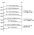
- the source device can inquire about the capability of the sink device using the RTSP M3 message, and can set the operation of the sink device using the RTSP M4 message.
- Wi-Fi Display Technical Specification Version 1.0.0 Wi-Fi Alliance Technical Committee, Wi-Fi Display Technical Task Group, August 24, 2012
- the existing method in which the source device controls the content encoding and decoding conditions as a master is inconvenient.
- a certain source device encodes content using an encoding method supported by the sink device and transmits the encoded content to the sink device.
- another source device can also encode another content with the same encoding method and transmit it to the sink device.
- the sink device has only one circuit that can decode the content by the encoding method, the sink device cannot simultaneously reproduce the content received from the two source devices.
- the decoding process is implemented not by hardware but by software.
- a wireless communication unit that establishes wireless connection with a plurality of encoding devices, and a decoding unit that respectively decodes content received from the plurality of encoding devices via the wireless communication unit,
- a reproduction unit that reproduces a plurality of contents decoded by the decoding unit, and a request decoding capability required by a set of content reproduced by the reproduction unit does not exceed an actual decoding capability of the decoding unit.
- a decoding device including a control unit that controls an encoding condition of content in a plurality of encoding devices.
- the decoding device respectively decodes content received from a plurality of encoding devices via a wireless connection, reproduces a plurality of decoded content, and reproduced content.
- a decoding method comprising: controlling a content encoding condition in the plurality of encoding devices by the decoding device so that a requested decoding capability required by the set of the plurality of sets does not exceed an actual decoding capability of the decoding device. Is provided.
- a wireless communication unit that establishes a wireless connection with a decoding device that decodes and reproduces content received from a plurality of devices, and the decoding device via the wireless communication unit
- An encoding unit that encodes content to be transmitted, and a request decoding capability required by a set of content reproduced by the decoding device is received from the decoding device so as not to exceed the actual decoding capability of the decoding device.
- a control unit that controls an encoding condition of the content in the encoding unit based on the control message.
- the content to be transmitted to the decoding device is encoded by the encoding device that transmits the content via a wireless connection to the decoding device that decodes and reproduces the content received from each of the plurality of devices. And based on a control message received from the decoding device, so that the requested decoding capability required by the set of content reproduced by the decoding device does not exceed the actual decoding capability of the decoding device,
- An encoding method including: controlling an encoding condition of content in an encoding device.
- the technique according to the present disclosure it is possible to appropriately reproduce content received from a plurality of source devices on the sink device without exceeding the decoding capability of the sink device.
- the above effects are not necessarily limited, and any of the effects shown in the present specification, or other effects that can be grasped from the present specification, together with or in place of the above effects. May be played.
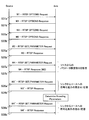
- FIG. 15 is a sequence diagram showing an example of an existing messaging flow in the capability negotiation procedure of FIG. 14. It is a sequence diagram which shows an example of the flow of the messaging between the sink device extended according to the 1st method, and a source device.
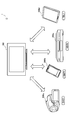
- FIG. 1 is an explanatory diagram for explaining an overview of a content reproduction system 1 according to an embodiment.
- the content reproduction system 1 includes a sink device 100, a source device 200a, a source device 200b, a source device 200c, and a source device 200d.
- the sink device 100 establishes a wireless connection with each of the source device 200a, the source device 200b, the source device 200c, and the source device 200d.
- the sink device is a device that decrypts the content received from the source device and reproduces the decrypted content.
- the sink device 100 is a digital television device.
- the source device is a device that encodes content as necessary and transmits the encoded content to the sink device.
- the content transmitted from the source device to the sink device typically includes at least one of video content and audio content.
- the source device 200a is a digital video camera having an identifier “DVC1”.
- the source device 200b is a smartphone having an identifier “SMP1”.
- the source device 200c is a content recorder having an identifier “VDR1”.
- the source device 200d is a tablet PC (Personal Computer) having an identifier “TBL1”.
- the technology according to the present disclosure is not limited to the illustrated example.
- any technology such as a desktop PC, a laptop PC, a PDA (Personal Digital Assistant), a mobile phone, a game device, a wearable device, or a storage device may be used.
- Applicable to various types of sink devices and source devices In the following description of this specification, when it is not necessary to distinguish the source device 200a, the source device 200b, the source device 200c, and the source device 200d from each other, these are collectively referred to as the source device 200.
- the wireless connection between the sink device 100 and the source device 200 is, for example, a wireless LAN (Local Area Network) system such as IEEE802.11a, 11b, 11g, 11n, 11ac, or 11ad, UWB (Ultra Wideband), or Zigbee. It may be formed according to any type of wireless communication method such as a wireless PAN (Personal Area Network) method or a wireless MAN (Metropolitan Area Network) method such as IEEE 802.16. Further, an intermediate device such as a wireless access point may or may not be interposed between the sink device 100 and the source device 200.
- a wireless LAN Local Area Network
- the sink device 100 and the source device 200 are connected by a wireless LAN system, and content is transmitted according to the Wi-Fi display messaging specification over the wireless LAN connection.
- the wireless LAN connection can be established between the sink device 100 and the source device 200 using Wi-Fi Direct or using a connection protocol called TDLS (Tunneled Direct Link Setup).
- TDLS Transmission Direct Link Setup
- a control channel for exchanging user input information may be formed between the sink device 100 and the source device 200.
- the control channel may be, for example, a TCP / IP (Transmission Control Protocol / Internet Protocol) -based UIBC (User Input Back Channel).
- the content may be transmitted using another remote desktop application such as VNC (Virtual Network Computing) instead of the Wi-Fi display.
- VNC Virtual Network Computing
- the source device 200 may provide, for example, video content acquired by shooting a subject with a camera or audio content acquired by collecting real-world audio with a microphone to the sink device. Further, the source device 200 may provide content received from the remote device via the network to the sink device. Further, the source device 200 may provide content read from the storage device (for example, a hard disk drive) to the sink device. On the other hand, in the present embodiment, the sink device 100 receives content from a plurality of source devices 200 in parallel, decodes the received content as necessary, and reproduces the content.
- the content encoding and decoding conditions are usually controlled mainly by the source device.
- the sink device 100 tries to reproduce a plurality of contents received from different source devices 200, such control on the source side causes inconvenience.
- the source device 200a encodes content using an encoding method supported by the sink device 100, and transmits the encoded content to the sink device 100.
- the source device 200b, 200c, or 200d can also encode another content using the same encoding method, and transmit the encoded content to the sink device 100.
- the sink device 100 has only one circuit that can decode the content by the encoding method (or the sink device 100 has a processor performance capable of decoding two contents in parallel by the encoding method).
- the sink device cannot play back the content received from these source devices at the same time.
- a mechanism is realized that enables the sink device to control the content encoding or decoding conditions on the premise that there are a plurality of source devices. Is desirable. Embodiments related to such a mechanism will be described in detail in the next section.
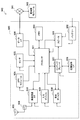
- FIG. 2 is a block diagram illustrating an example of the configuration of the sink device 100 according to an embodiment.
- the sink device 100 includes a wireless communication unit 110, a stream acquisition unit 120, a decoding unit 130, a video playback unit 140, an audio playback unit 150, a playback control unit 160, a storage unit 170, and a user interface unit 180. .
- the wireless communication unit 110 is a wireless interface that mediates wireless communication between the sink device 100 and other devices.
- the wireless communication unit 110 establishes a wireless connection with a plurality of source devices (encoding devices that encode content) 200.
- the wireless communication unit 110 receives a wireless signal including content data transmitted by the source device 200 via a wireless connection via an antenna.
- the wireless communication unit 110 outputs a reception signal including content data to the stream acquisition unit 120.
- the wireless communication unit 110 can transmit and receive a wireless signal including a control message to and from the source device 200.
- the control message transmitted to the source device 200 is generated by the reproduction control unit 160 described later. Further, the control message received from the source device 200 is interpreted by the playback control unit 160.
- the wireless communication unit 110 may be able to use a plurality of frequency channels having different transmission rates in parallel or selectively.
- the plurality of frequency channels may be channels having transmission rates of 2.4 GHz, 5 GHz, and 60 GHz, respectively.
- the radio communication unit 110 can switch the frequency channel to be used for receiving content from each source device 200 according to the assignment by the reproduction control unit 160 described later.
- high bit rate content eg, content displayed in a multi-frame main window
- low bit rate content eg, displayed in a multi-frame sub-window.
- Content can be transmitted on a channel with a low transmission rate.
- the wireless communication unit 110 measures the connection quality of each frequency channel and outputs a quality index (for example, received signal strength or SNR (Signal-to-Noise Ratio)) indicating the measurement result to the reproduction control unit 160. Good.
- a quality index for example, received signal strength or SNR (Signal-to-Noise Ratio)
- the stream acquisition unit 120 acquires a bit stream of content to be reproduced (for example, video content or audio content) from the received signal input from the wireless communication unit 110. Then, the stream acquisition unit 120 outputs the bit stream acquired for the content to be reproduced to the decoding unit 130.
- a bit stream of content to be reproduced for example, video content or audio content
- the stream acquisition unit 120 measures a quality index (for example, BER (Bit Error Rate) or PER (Packet Error Rate)) for evaluating the connection quality of the wireless connection for each stream, and uses the quality index as the playback control unit 160. May be output.
- a quality index for example, BER (Bit Error Rate) or PER (Packet Error Rate)
- the decoding unit 130 decodes each content from the bit stream of the content received from one or more source devices 200.
- the decoding unit 130 outputs the decoded video content to the video reproduction unit 140.
- the decoding unit 130 outputs the decoded audio content to the audio reproduction unit 150.
- the decryption unit 130 can decrypt a plurality of contents in parallel.
- the content is compression-encoded, the content is expanded through the decoding process in the decoding unit 130.
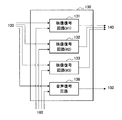
- FIG. 3A is a block diagram illustrating a first example of a detailed configuration of the decoding unit 130 of the sink device 100.
- the decoding unit 130 includes a first video decoding circuit 131, a second video decoding circuit 132, a third video decoding circuit 133, and an audio decoding circuit 136.
- the first video decoding circuit 131 is, for example, H.264 as a video codec. It is a decoding circuit that supports H.265 / HEVC.
- the second video decoding circuit 132 and the third video decoding circuit 133 are, for example, H.264 as a video codec. This is a decoding circuit that supports H.264 / AVC.
- the audio decoding circuit 136 is a decoding circuit that supports an audio codec such as AAC, MP3, or LPCM.
- the actual decoding capability of the decoding unit 130 corresponds to the overall capabilities of these decoding circuits.
- the actual decoding capability depends on at least one of the number of decoding circuits and the codec type, resolution, rate (such as frame rate or sampling rate) and quality level (such as bit depth or quantization step) supported by each decoding circuit. Can be expressed.
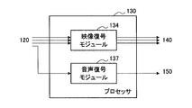
- FIG. 3B is a block diagram illustrating a second example of a detailed configuration of the decoding unit 130 of the sink device 100.
- the decoding unit 130 is configured by a processor, and the processor executes a software module read from a memory (not shown).
- the software modules executed by the decoding unit 130 include a video decoding module 134 and an audio decoding module 137, for example.
- the video decoding module 134 is an H.264 video codec. H.265 / HEVC and H.264. H.264 / AVC may be supported.
- the audio decoding module 137 may support AAC, MP3, LPCM, or the like as an audio codec.
- the actual decoding capability of the decoding unit 130 depends on the processor performance.
- the processor performance required to decode the content may depend on decoding conditions such as the codec type, resolution, rate, and quality level of the content to be decoded.
- the configuration of the decoding unit 130 is not limited to the above-described example.
- the decoding unit 130 may have more or fewer decoding circuits.
- the decoding unit 130 may include both a decoding circuit as hardware and a processor that executes software modules for video decoding and audio decoding.
- the decoding unit 130 may support a codec type different from that exemplified above.
- the video reproducing unit 140 and the audio reproducing unit 150 are used for reproducing a plurality of contents decoded by the decoding unit 130.
- the video reproduction unit 140 sequentially outputs each frame of the video content decoded by the decoding unit 130 to the display.
- the video playback unit 140 may, for example, merge (or blend) the frames of the video contents into one image and output a multi-frame display image to the display.
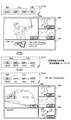
- FIG. 4A is an explanatory diagram illustrating a first example of a configuration of a display image output to the display by the video reproduction unit 140 of the sink device 100.
- the display image 142 includes a main window 145a, a sub window 145b, a sub window 145c, and a standby device window 146.
- the main window 145a is a window for displaying main content that can be selected based on user input.
- the sub window 145b and the sub window 145c are windows for displaying sub contents that can be decoded in parallel with the main content.
- the main content and the sub content constitute a content reproduction set.
- the standby device window 146 is a list of source devices 200 (hereinafter referred to as a standby list) in which wireless connection with the sink device 100 is maintained at that time, although the content being played back is not provided to the sink device 100. ) Is a window for displaying.
- the content received from the source device 200a is displayed in the main window 145a
- the content received from the source device 200b is displayed in the subwindow 145b
- the content received from the source device 200c is displayed in the subwindow 145c.
- the content from the source device 200d is not reproduced
- the icon of the source device 200d (and an identifier for identifying the device) is displayed in the standby device window 146.
- FIG. 4B is an explanatory diagram illustrating a second example of a configuration of a display image output to the display by the video reproduction unit 140 of the sink device 100.
- a display image 143a output to the first display and a display image 143b output to the second display are shown.
- the display image 143a includes a main window 145a.
- the display image 143b includes a sub window 145b, a sub window 145c, and a standby device window 146.
- the video reproduction unit 140 may be able to output separate display images to a plurality of displays. Each of these display images may include any number and type of windows.
- FIG. 4C is an explanatory diagram illustrating a third example of a configuration of a display image output to the display by the video reproduction unit 140 of the sink device 100.
- the display image 144 includes a main window 145a, a sub window 145b, and a sub window 145c, but does not include the standby device window 146 as illustrated in FIGS. 4A and 4B. Thus, it is not essential to display the standby device window (or standby list).
- the display may be configured integrally with the sink device 100, or may be connected to the sink device 100 in a replaceable manner.
- the video playback unit 140 can adjust the display attributes (eg, frame size) of the video content to be played in accordance with the desired window configuration and the specifications of the output destination display.
- a monitor or projector may be used as the display.
- the audio reproducing unit 150 sequentially outputs the audio signal of the audio content decoded by the decoding unit 130 to the speaker.
- the content played back by the audio playback unit 150 may be audio content associated with video content that is main content or sub-content, or may be separate audio content not related to the video content.
- the playback control unit 160 has the requested decoding capability required by the content set (content playback set) played by the video playback unit 140 and the audio playback unit 150 exceeds the actual decoding capability of the decoding unit 130. In such a case, the content encoding conditions in the plurality of source devices 200 that are the transmission sources of the content are controlled.
- a content playback set may typically be generated and updated based on user input obtained via the user interface unit 180.
- the playback control unit 160 determines the requested decoding capability for the latest content playback set that is initially generated or updated, and compares the determined requested decoding capability with the actual decoding capability of the decoding unit 130.
- the playback control unit 160 can maintain the content playback set and its encoding conditions as they are.
- the reproduction control unit 160 changes the encoding condition in at least one source device 200 in order to lower the requested decoding capability.
- the reproduction control unit 160 grasps in advance the encoding capabilities of the source device 200. More specifically, the playback control unit 160 collects encoding capability information from each source device 200 by transmitting a capability inquiry message to each of the source devices 200 via the wireless communication unit 110, and collects the collected code Information is stored in the storage unit 170. Then, the reproduction control unit 160 determines the encoding condition in the source device 200 within a range allowed by the collected encoding capability information of the source device 200.
- the Wi-Fi display specification defined in Non-Patent Document 1 defines a message for inquiring decoding capability information from the source device to the sink device, while the encoding capability from the sink device to the source device is defined.
- a message to query is not defined. This is because, in existing methods, the content encoding and decoding conditions are usually controlled mainly by the source device.
- a capability inquiry message for inquiring the encoding capability from the sink device 100 to the source device 200 is introduced. Thereby, the sink device 100 can control the encoding conditions in the plurality of source devices 200 as a master.
- the encoding condition may be a condition related to at least one of the codec type, resolution, rate, and quality level used in each source device 200.
- the playback controller 160 may While decoding circuits supporting H.265 / HEVC are lacking in demand, H.264 / AVC, when there is a vacancy in the decoding circuit.
- the encoding condition of the source device 200 that encodes the content with H.265 / HEVC is H.265. It can be changed to H.264 / AVC.
- the reproduction control unit 160 informs the source device 200 to encode the content at a lower resolution, a lower rate, or a lower quality level. Can be requested. Thereby, the required decoding capability can be adapted to the actual decoding capability.
- Such a change in the encoding condition is allowed when the encoding capability information indicates that the source device 200 has the ability to encode or transmit the content with the changed encoding condition.
- the codec type may include not only the compression encoding method but also the non-compression method. Although transmission in the uncompressed format is performed only on a wireless connection with a high transmission rate because the content to be transmitted has a high bit rate, there is almost no load on the encoder and decoder compared with the compression encoding method. . Therefore, as long as the requested decoding capability exceeds the actual decoding capability as long as permitted by the encoding capability information, the playback control unit 160 sends the content to the source device 200 that encodes the content with a specific codec type. May be requested to be transmitted without compression encoding. The playback control unit 160 may switch the codec type to be applied to the source device 200 between the compression coding method and the non-compression method according to the transmission rate or connection quality of the allocated frequency channel.
- the reproduction control unit 160 determines the change of the encoding condition (including the start or stop of the reproduction)
- the reproduction control unit 160 sends a message for setting the determined encoding condition via the wireless communication unit 110 to the source involved in the change. Transmit to device 200.
- a message for setting the encoding condition via the wireless communication unit 110 to the source involved in the change.
- encoding from the sink device 100 to the source device 200 is performed.
- a setting request message for setting conditions is introduced.
- the reproduction control unit 160 may control the encoding condition in each source device 200 based on the connection quality of the wireless connection with each source device 200.
- the playback control unit 160 monitors a quality index input from the wireless communication unit 110 or the stream acquisition unit 120. Then, when it is detected that the connection quality has deteriorated for a certain source device 200, the playback control unit 160 reduces the resolution, rate, or quality level of the content received from the source device 200. As a result, the bit rate of the content is reduced, so that the risk of loss of content data over a wireless connection with degraded quality can be reduced.
- the reproduction control unit 160 may control the encoding condition in each source device 200 based on the power supply state of each source device 200. For example, in a situation where any content is to be excluded from the content playback set, the playback control unit 160 may preferentially exclude content from the source device 200 that is battery-driven (or has a low remaining battery level). Good. Further, the playback control unit 160 may preferentially lower the resolution, rate, or quality level of content from the source device 200 that is battery-driven. The playback control unit 160 may determine the codec type of the source device 200 that is battery-driven so that content decoding and re-encoding (or transcoding) are not required. Thereby, the consumption of the battery as a whole system can be suppressed while the request decoding capability is lowered.
- each source device 200 may provide priority condition information for specifying the encoding condition to be prioritized to the sink device 100 through a prior message exchange procedure.
- the priority condition information is stored in the storage unit 170, and can be referred to when the reproduction control unit 160 determines the encoding condition in each source device 200.
- the playback control unit 160 may further control the frequency channel of the wireless connection with the source device 200 according to the encoding condition in the source device 200. For example, when it is recognized from the encoding condition that the bit rate of the content to be received from a certain source device 200 is increased, the playback control unit 160 uses a higher transmission rate for the wireless connection with the source device 200. A frequency channel having a higher frequency (or better connection quality) is allocated. Further, when the transmission rate of the frequency channel that can be allocated is lower than the bit rate assumed for a certain content, the playback control unit 160 may lower the resolution, rate, or quality level of the content. Thereby, stable transmission of content can be ensured.
- the playback control unit 160 can also control the exchange of messages with the source device 200.
- the message transmitted to the source device 200 may include the above-described capability inquiry message and setting request message for controlling the encoding condition in the source device 200.
- the message received from the source device 200 may include a response message from the source device 200 in response to the capability inquiry message and the setting request message described above.
- the playback control unit 160 may transmit and receive a control message including commands related to content playback (for example, playback start, playback stop, fast forward, rewind, etc.) via a control channel between devices.
- the playback control unit 160 can control the operations of the video playback unit 140 and the audio playback unit 150 in response to detection of such a command.
- the storage unit 170 can store a program and data for controlling content decryption and reproduction in the sink device 100.
- the storage unit 170 can store, for example, encoding capability information collected from a plurality of source devices 200 and the above-described priority condition information.
- the storage unit 170 can store actual decoding capability information indicating the actual decoding capability of the decoding unit 130.
- the actual decoding capability information may be fixedly defined in advance. Instead, the playback control unit 160 may continuously monitor the load applied to the decoding unit 130, dynamically recalculate the actual decoding capability of the decoding unit 130, and update the actual decoding capability information. For example, if the decoding process is implemented in software, the processor that executes the software may also execute other processes, so the processor performance available for the decoding process is dynamically recalculated. It is beneficial.
- the user interface unit 180 receives user input via an input device (not shown) of the sink device 100.
- the sink device 100 may accept an input signal generated in specific hardware such as a remote controller, a touch panel, a keyboard, a mouse, a button, or a switch as a user input.
- the sink device 100 may accept a voice command acquired through a microphone, a gesture command acquired through a camera, or a sensor command acquired through a sensor as a user input.
- the user interface unit 180 outputs the received user input to the reproduction control unit 160.
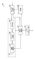
- FIG. 5 is a block diagram illustrating an example of the configuration of the source device 200 according to an embodiment.
- the source device 200 includes a wireless communication unit 210, a storage unit 220, a content acquisition unit 230, an encoding unit 240, a stream transmission unit 250, an encoding control unit 260, and a user interface unit 270.
- the wireless communication unit 210 is a wireless interface that mediates wireless communication between the source device 200 and other devices.
- the wireless communication unit 210 establishes a wireless connection with the sink device 100.
- the sink device 100 is a decoding device that decodes and plays back content received from a plurality of source devices.
- the wireless communication unit 110 transmits a wireless signal including the content data generated by the stream transmission unit 250 to the sink device 100 over the wireless connection via the antenna. Further, the wireless communication unit 210 can also transmit and receive a wireless signal including a control message to and from the sink device 100.
- the control message transmitted to the sink device 100 is generated by the encoding control unit 260 described later. Further, the control message received from the sink device 100 is interpreted by the encoding control unit 260.
- the storage unit 220 can store a program and data for controlling the encoding and transmission of content in the source device 200.
- the storage unit 220 stores in advance encoding capability information indicating the encoding capability of the source device 200 itself.
- the encoding capability information may indicate at least one of codec type, resolution, rate, and quality level supported by the encoding unit 240, for example.
- the encoding condition can be specified within the range of the encoding capability indicated by the encoding capability information.
- the storage unit 220 may store priority condition information for specifying an encoding condition (priority condition) that is preferably prioritized in the source device 200.
- the priority condition can be set by the user or dynamically specified by the encoding control unit 260.
- the storage unit 220 may further store any type of content that can be provided to the sink device 100.
- the storage unit 220 includes content including video captured by a camera and audio collected by a microphone, content received and recorded from a broadcasting station, content downloaded from a content server, content read from a peripheral device, Or it may store content generated by some user application.
- the content acquisition unit 230 acquires content to be provided to the sink device 100 from the storage unit 220 or another data source, and outputs the acquired content to the encoding unit 240.
- Other data sources may include, for example, a camera and microphone of the source device 200, or a remode device (eg, a content server or a web camera with a microphone) accessible by the source device 200.
- Which content is to be provided to the sink device 100 can be specified by a user input detected by the user interface unit 270 or by a control message received from the sink device 100.
- the content acquisition unit 230 When the acquired content is encoded with a codec type different from the encoding condition instructed from the sink device 100, the content acquisition unit 230 once decodes the content and outputs the decoded content to the encoding unit 240. Also good.
- the encoding unit 240 encodes content to be transmitted to the sink device 100 input from the content acquisition unit 230, and generates a content bitstream. Then, the encoding unit 240 outputs the generated bit stream to the stream transmission unit 250.
- the encoding condition of the content in the encoding unit 240 is controlled by the encoding control unit 260 based on the control message received from the sink device 100.
- the encoding conditions for video content may include the codec type, resolution, frame rate, and image quality level of the video codec used.
- the coding conditions for audio content can include the codec type, sampling rate, and sound quality level of the audio codec used.
- the encoding unit 240 may generate a bitstream of the content in an uncompressed format without compressing the content.
- the encoding unit 240 may have one or more encoding circuits as hardware.
- the encoding unit 240 may include a processor that can execute software modules for video encoding and audio encoding.
- the encoding unit 240 may include both an encoding circuit as hardware and a processor capable of executing software modules.
- the encoding unit 240 can support any codec type.
- the stream transmission unit 250 transmits the bit stream of the encoded content input from the encoding unit 240 to the sink device 100 via the wireless communication unit 210.
- the stream transmission unit 250 may generate a multimedia stream by multiplexing the video content stream and the audio content stream, and may transmit the generated multimedia stream.
- the encoding control unit 260 controls the content encoding conditions in the encoding unit 240 based on the control message received from the sink device 100.
- the control message received from the sink device 100 specifies an encoding condition determined so that the requested decoding capability required by the set of content reproduced by the sink device 100 does not exceed the actual decoding capability of the sink device 100.
- the encoding control unit 260 may cause the encoding unit 240 to encode the video content with the codec type, resolution, frame rate, and image quality level specified by the sink device 100.
- the encoding control unit 260 may cause the encoding unit 240 to encode the audio content with the codec type, sampling rate, and sound quality level specified by the sink device 100.
- the encoding control unit 260 transmits the encoding capability information indicating the encoding capability of the encoding unit 240 to the wireless communication.
- the data is transmitted to the sink device 100 via the unit 210.
- the encoding control unit 260 may transmit the encoding capability information to the sink device 100 as a response to the capability inquiry message received from the sink device 100.
- the source device inquires the sink device about the decoding capability, and the source device mainly determines the content encoding and decoding conditions based on the result.
- the control message specifies an encoding condition within the range indicated by the encoding capability information transmitted to the sink device 100.
- the control message may be a setting request message for requesting setting of an encoding condition from the sink device 100 to the source device 200 described above. If the coding capability information permits, the setting request message may specify a non-compression method as the codec type. When the non-compression method is designated as the codec type, the encoding control unit 260 may instruct the encoding unit 240 to generate a content bitstream in an uncompressed format without compressing the content. When the content acquired by the content acquisition unit 230 has already been encoded with the codec type specified in the setting request message, the encoding control unit 260 decodes and re-encodes (or transcodes) the content. May be skipped.
- the encoding control unit 260 may notify the sink device 100 of the power state of the source device 200 (for example, whether it is battery-operated or connected to the power source, or the remaining battery level). In this case, the sink device 100 can control the encoding condition in the source device 200 in order to suppress battery consumption in the source device 200 that is battery-driven, for example, based on the power state of the source device 200.
- the encoding control unit 260 may transmit priority condition information for specifying an encoding condition to be prioritized to the sink device 100 through a prior message exchange procedure.
- the priority condition information is defined based on restrictions or requirements for individual devices such as power saving or processing load reduction, and can be referred to when the sink device 100 determines the coding conditions in the source device 200.
- the encoding control unit 260 may further control the frequency channel of the wireless connection with the sink device 100 according to the control from the sink device 100. For example, when it is recognized that the bit rate of content to be transmitted to the sink device 100 is increased, the wireless connection with the sink device 100 has a higher transmission rate (or better connection quality). A frequency channel is assigned.
- the encoding control unit 260 can instruct the wireless communication unit 210 to use the frequency channel allocated by the sink device 100.
- the encoding control unit 260 may measure a quality index (for example, BER or PER) for evaluating the connection quality of the wireless connection with the sink device 100, and transmit the quality index to the sink device 100. .
- a quality index for example, BER or PER
- the encoding control unit 260 can also control the exchange of messages with the sink device 100.
- the message received from the sink device 100 may include the above-described capability inquiry message and setting request message for controlling the encoding condition in the source device 200.
- the message transmitted to the sink device 100 can include a response message to the above-described capability inquiry message and setting request message.
- the encoding control unit 260 transmits a control message including a command corresponding to the detected user input to a control channel between devices. It may be transmitted to the sink device 100 via
- the wireless communication unit 210 can receive a control message instructing to stop playback of content.
- the encoding control unit 260 may shift the operation mode of the source device 200 to the standby mode and partially stop the power supply to each unit of the source device 200 during the standby mode.
- the wireless communication unit 210 operates intermittently, for example, and can receive a control message from the sink device 100 during a periodic active period. That is, the wireless connection between the sink device 100 and the source device 200 can be maintained even during the standby mode.
- the encoding control unit 260 may return the operation mode of the source device 200 to the active mode when a control message instructing the start of content playback is received during the standby mode.
- the user interface unit 270 accepts user input via an input device (not shown) of the source device 200.
- the source device 200 may accept an input signal generated in specific hardware such as a remote controller, a touch panel, a keyboard, a mouse, a button, or a switch as a user input.
- the source device 200 may accept a voice command acquired through a microphone, a gesture command acquired through a camera, or a sensor command acquired through a sensor as a user input.
- the user interface unit 270 outputs the received user input to the encoding control unit 260.
- the source device 200 may also include a video playback unit and an audio playback unit.
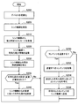
- FIG. 6 is a flowchart showing an example of the flow of content reproduction processing executed by the sink device 100 according to this embodiment.
- the reproduction control unit 160 of the sink device 100 initializes each unit of the sink device 100 (step S100).
- the playback control unit 160 broadcasts a search signal from the wireless communication unit 110 to the surroundings of the sink device 100 or detects a search signal broadcast from the source device 200, so that one of the surroundings is present.
- the above source device 200 is found (step S105).
- the reproduction control unit 160 transmits a capability inquiry message from the wireless communication unit 110 to the discovered source device 200 (step S110).
- the playback control unit 160 receives the encoding capability information returned from the source device 200 as a response to the capability inquiry message (step S120).
- the playback control unit 160 establishes a wireless connection with the source device 200 that can provide the content (step S130). Note that the processing in steps S105 to S130 may be repeated continuously while the content reproduction control described below is being executed. Each time a new source device 200 is discovered, the sink device 100 can establish a wireless connection with the discovered source device 200.
- the playback control unit 160 determines whether to update the content playback set (step S135). For example, the playback control unit 160 adds content designated as main content or sub-content by the user to the content playback set.
- the update process in step S140 for updating the content reproduction set will be described in detail later.
- the reproduction control unit 160 transmits the setting request message to the source device 200 whose encoding condition is changed, thereby encoding the encoding condition. Is requested (step S160).
- the wireless communication unit 110 receives content included in the content reproduction set from the plurality of source devices 200 (step S170).
- the bit stream of each content can be extracted from the received signal by the stream acquisition unit 120.
- the decryption unit 130 decrypts the main content and the sub-content from the received content bitstream (step S172).
- the video playback unit 140 blends the decoded video content frame into a multi-frame display image (step S174).
- the video reproduction unit 140 adds the standby device icon (or text) to the standby list displayed on the display image (step S176).
- the video reproduction unit 140 displays the multi-frame video on the display (step S178).
- the audio reproducing unit 150 outputs the audio of the decoded audio content to the speaker (Step S180).
- the reproduction control unit 160 monitors a control trigger related to the update of the content reproduction set (step S190).
- the control trigger here may include, for example, one or more of detection of user input instructing update of the content reproduction set, increase in load applied to the decoding unit 130, and deterioration of connection quality of the wireless connection.
- the processes of steps S140 and S160 described above are skipped, and reception, decoding, and reproduction of content from the source device 200 are repeated.
- an update process for updating the content reproduction set described below can be executed.
- FIG. 7 is a flowchart showing an example of a detailed flow of update processing for updating the content playback set corresponding to step S140 in FIG.
- the update process shown in FIG. 7 branches depending on the contents of the user input. For example, when the main content is designated by the user (step S141), the reproduction control unit 160 sets the designated content as the main content (step S142). When the sub content is designated by the user (step S143), the reproduction control unit 160 sets the designated content as the sub content (step S144). When the standby device is designated by the user (step S145), the playback control unit 160 sets the designated source device 200 as the standby device (step S146).
- the playback control unit 160 determines the required decoding capability of the playback set (step S148).
- the required decoding capability for video content may depend on the codec type, resolution, frame rate, and image quality level of the video content being played back.
- the required decoding capability for audio content may depend on the codec type, sampling rate, and sound quality level of the audio content being played back.
- the required decoding capability may be expressed by the number of decoding circuits required or the required processor performance.
- the playback control unit 160 determines whether or not the determined requested decoding capability exceeds the actual decoding capability of the decoding unit 130 (step S148).
- the reproduction control unit 160 changes the encoding condition of the content reproduction set and lowers the requested decoding capability (step S149).
- the change of the encoding condition here may include, for example, one or more of the following items a1) to a9) within a range allowed by the encoding capability information acquired from each source device 200. .
- the reproduction control unit 160 sets the encoding condition within a range not exceeding the actual decoding capability. It may be changed to increase the request decoding capability (step S151).
- the change of the encoding condition here may include, for example, one or more of the following items b1) to b9) within a range allowed by the encoding capability information acquired from each source device 200. .
- step S152 the reproduction control unit 160 determines whether there is a wireless connection with deteriorated connection quality (step S152). For example, if the transmission rate of a certain wireless connection is lower than the bit rate of the content to be conveyed, it can be determined that the connection quality of that wireless connection has deteriorated. When there is a wireless connection with deteriorated connection quality, the playback control unit 160 changes the encoding condition and lowers the bit rate of the corresponding content (step S153). Note that the change of the encoding condition according to the connection quality of the wireless connection may not necessarily be executed, or may be executed in the source device 200 on the transmission side.
- FIG. 8 is a flowchart showing an example of the flow of content transmission processing executed by the source device 200 according to this embodiment.
- the encoding control unit 260 of the source device 200 initializes each unit of the source device 200 (step S200).
- the coding control unit 260 detects the sink device 100 by detecting the search signal broadcast from the sink device 100 or broadcasting the search signal from the wireless communication unit 210 (step S205).
- the encoding control unit 260 receives a capability inquiry message from the sink device 100 via the wireless communication unit 210 (step S210).
- the encoding control unit 260 transmits a response message including the encoding capability information to the sink device 100 as a response to the capability inquiry message (step S220).
- the encoding control unit 260 establishes a wireless connection with the sink device 100 (step S230).
- the encoding control unit 260 sets the encoding condition for encoding the content according to the request (step S240).
- the encoding condition is described in a setting request message received from the sink device 100, for example.
- step S250 content transmission is triggered (step S250).
- the content acquisition unit 230 acquires content to be transmitted to the sink device 100 from the storage unit 220 or another data source (step S252).
- the encoding unit 240 encodes the content input from the content acquisition unit 230 in accordance with the encoding condition set by the encoding control unit 260 (step S254).
- the stream transmission unit 250 transmits the bit stream of the encoded content input from the encoding unit 240 to the sink device 100 via the wireless communication unit 210 (step S256).
- the encoding control unit 260 monitors a control trigger.
- the control trigger here may include, for example, reception of a setting request message from the sink device 100 and detection of a user input in the user interface unit 270.
- the encoding control unit 260 can set the encoding condition again according to the request in step S240 described above. If no control trigger is detected, content acquisition, encoding and transmission are repeated. Note that content acquisition, encoding, and transmission are skipped while the source device 200 is selected as a standby device.
- Control scenario> In this section, some control scenarios related to control of encoding conditions in the content reproduction system 1 will be described with reference to the drawings.
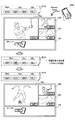
- FIG. 9 is an explanatory diagram for describing an exemplary first control scenario related to control of encoding conditions.
- the content playback set RL10 includes main content from the source device 200a (identifier “DVC1”) and two sub-contents from the source device 200b (identifier “SMP1”) and the source device 200c (identifier “VDR1”).
- the source device 200d (identifier “TBL1”) is a standby device. Content received from the source device 200a is displayed in the main window 145a of the display image. Content received from the source device 200b is displayed in the sub window 145b. Content received from the source device 200c is displayed in the sub window 145c. In the standby device window 146, an icon of the source device 200d that is a standby device is displayed.
- the playback control unit 160 of the sink device 100 updates the content playback set RL10 to the content playback set RL11.
- the content from the source device 200d (identifier “TBL1”) is set as the main content.
- the decoding unit 130 has only three decoding circuits that can decode video content, the requested decoding capability of the content reproduction set RL11 exceeds the actual decoding capability of the decoding unit 130.
- the playback control unit 160 updates the content playback set RL11 to the content playback set RL12, for example.
- content from the source device 200a (identifier “DVC1”) is excluded from the playback target, and the source device 200a is changed to a standby device.
- the requested decryption capability of the content reproduction set RL12 does not exceed the actual decryption capability of the decryption unit 130.
- a display image corresponding to the content reproduction set RL12 is shown.
- Content received from the source device 200d (identifier “TBL1”) is displayed in the main window 145a.
- the standby device window 146 displays an icon of the source device 200a changed to the standby device.
- the wireless connection between the wireless communication unit 110 and the source device 200a is maintained even after the source device 200a is iconified in this way. Thereby, when the content from the source device 200a is reproduced again, the delay time until the reproduction is started (for example, the time required for setting up the wireless connection) can be shortened.
- FIG. 10 is an explanatory diagram for describing an exemplary second control scenario related to control of encoding conditions.
- the content reproduction set RL20 includes main content from the source device 200a (identifier “DVC1”) and two sub-contents from the source device 200b (identifier “SMP1”) and the source device 200c (identifier “VDR1”).
- the source device 200d (identifier “TBL1”) is a standby device. Content received from the source device 200a is displayed in the main window 145a of the display image. Content received from the source device 200b is displayed in the sub window 145b. Content received from the source device 200c is displayed in the sub window 145c. In the standby device window 146, an icon of the source device 200d that is a standby device is displayed.
- the playback control unit 160 of the sink device 100 updates the content playback set RL20 to the content playback set RL21.
- the content from the source device 200b (identifier “SMP1”) is set as the main content.
- SMP1 the content from the source device 200b
- the reproduction control unit 160 updates the content reproduction set RL21 to the content reproduction set RL22.
- the content from the source device 200a (identifier “DVC1”) is changed to a sub-content.
- the requested decryption capability of the content reproduction set RL22 does not exceed the actual decryption capability of the decryption unit 130.
- a display image corresponding to the content reproduction set RL22 is shown.
- the main window 145a content received from the source device 200b (identifier “SMP1”) is displayed.
- the content received from the source device 200a (identifier “DVC1”) is displayed in the sub window 145b.
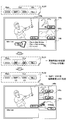
- FIG. 11 is an explanatory diagram for describing an exemplary third control scenario related to the control of the encoding condition.
- the content reproduction set RL30 includes main content from the source device 200a (identifier “DVC1”) and two sub-contents from the source device 200b (identifier “SMP1”) and the source device 200c (identifier “VDR1”).
- the source device 200d (identifier “TBL1”) is a standby device. Content received from the source device 200a is displayed in the main window 145a of the display image. Content received from the source device 200b is displayed in the sub window 145b. Content received from the source device 200c is displayed in the sub window 145c. In the standby device window 146, an icon of the source device 200d that is a standby device is displayed.
- the playback control unit 160 of the sink device 100 updates the content playback set RL30 to the content playback set RL31.
- the content from the source device 200d (identifier “TBL1”) is set as the sub-content.
- the requested decoding capability exceeds the actual decoding capability of the processor of the decoding unit 130.
- the reproduction control unit 160 updates the content reproduction set RL31 to the content reproduction set RL32.
- the resolution of the sub content from the source device 200b (identifier “SMP1”) and the source device 200c (identifier “VDR1”) is changed to low resolution (LD).
- LD low resolution
- the requested decryption capability of the content reproduction set RL32 does not exceed the actual decryption capability of the decryption unit 130.
- a display image corresponding to the content reproduction set RL32 is shown in the lower part of FIG. The window sizes of the sub-windows 145b and 145c are reduced, and each of these windows displays low-resolution sub-contents.
- a new subwindow 145d is added, and the subwindow 145d displays content received from the source device 200d (identifier “TBL1”).
- the window configuration (the number and size of windows) of the display image may be dynamically changed following the encoding condition of the content reproduction set.
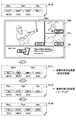
- FIG. 12 is an explanatory diagram for describing an exemplary fourth control scenario related to the control of the encoding condition.
- the content reproduction set RL40 includes main content from the source device 200a (identifier “DVC1”) and two sub-contents from the source device 200b (identifier “SMP1”) and the source device 200c (identifier “VDR1”).
- the source device 200d (identifier “TBL1”) is a standby device.
- the main content is H.264 on the source device 200a. It is encoded with H.265 / HEVC.
- the two sub-contents are stored in the source device 200b and 200c in the H.264 format. It is encoded by H.264 / AVC.
- the playback control unit 160 of the sink device 100 updates the content playback set RL40 to the content playback set RL41.
- content from the source device 200d (identifier “TBL1”) is set as the main content.
- the decoding unit 130 since the decoding unit 130 has only three decoding circuits that can decode video content, the requested decoding capability of the content reproduction set RL41 exceeds the actual decoding capability of the decoding unit 130.
- the playback control unit 160 further updates the content playback set RL41 to the content playback set RL42.
- content playback set RL42 content from the source device 200a (identifier “DVC1”) is set as sub-content, and content from the source device 200c (identifier “VDR1”) is excluded from playback targets.
- the main content from the source device 200d (identifier “TBL1”) is H.264. It is encoded with H.265 / HEVC. However, for example, the decoding unit 130 is H.264. Since only one decoding circuit capable of decoding video content with H.265 / HEVC is provided, the requested decoding capability of the content reproduction set RL42 still exceeds the actual decoding capability of the decoding unit 130.
- the reproduction control unit 160 further updates the content reproduction set RL42 to the content reproduction set RL43.
- the main content from the source device 200d (identifier “TBL1”) is H.264. It is encoded by H.264 / AVC.
- the requested decryption capability of the content reproduction set RL43 does not exceed the actual decryption capability of the decryption unit 130.
- Which source device codec type should be changed may be determined based on, for example, encoding capability information collected in advance from each source device. In the control scenario of FIG. 12, the codec type for the main content from the source device 200d is H.264.
- the reason for changing to H.264 / AVC is, for example, that the source device 200d is H.264. H.265 / HEVC and H.264. H.264 / AVC is supported, while the source device 200a is H.264. It may be that only H.265 / HEVC is supported.
- FIG. 13 is an explanatory diagram for explaining an exemplary fifth control scenario related to the control of the encoding condition.
- the content reproduction set RL50 includes main content from the source device 200a (identifier “DVC1”) and two sub-contents from the source device 200b (identifier “SMP1”) and the source device 200c (identifier “VDR1”).
- the source device 200d (identifier “TBL1”) is a standby device.
- the playback control unit 160 of the sink device 100 updates the content playback set RL50 to the content playback set RL51.
- the content from the source device 200d (identifier “TBL1”) is set as the main content.
- the decoding unit 130 has only three decoding circuits capable of decoding video content, and is a default video codec for main content. Since there is only one decryption circuit capable of decrypting content by H.265 / HEVC, the requested decryption capability of the content reproduction set RL51 exceeds the actual decryption capability of the decryption unit 130.
- the reproduction control unit 160 updates the content reproduction set RL51 to the content reproduction set RL52.
- the content from the source device 200a (identifier “DVC1”) is changed to a sub-content, and the codec type of the content is changed to an uncompressed (NC) system.
- the source device 200a transmits the content to the sink device 100 without compression encoding.
- the decoding unit 130 of the sink device 100 does not have to execute a decoding process for expanding the sub-content received from the source device 200a.
- the requested decryption capability of the content reproduction set RL52 does not exceed the actual decryption capability of the decryption unit 130.
- a display image corresponding to the content reproduction set RL52 is shown. In the display image, a new subwindow 145e is added, and the subwindow 145e displays the content received from the source device 200a (identifier “DVC1”).
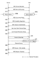
- Messaging sequence (example of Wi-Fi display)>
- the messaging sequence conforms to the specification of the Wi-Fi display, but the sequence may be partially extended to realize the technology according to the present disclosure.
- FIG. 14 is a sequence diagram schematically showing a flow of messaging between devices in the Wi-Fi display.
- only one source device and one sink device are shown for the sake of simplicity. In practice, however, multiple source devices and a single sink device may exchange messages according to the procedure described in this section.
- a device discovery procedure (WFD Device Discovery) is executed between the sink device 100 and the source device 200 (step S10).
- the device discovery procedure at least one device transmits a search signal, and the other device that has received the search signal returns a response signal. Thereby, the sink device 100 and the source device 200 recognize each other's existence.
- a service discovery procedure (WFD Service Discovery) is executed between the sink device 100 and the source device 200 (step S15).
- the service discovery procedure is optional and may be omitted from the sequence.
- the service discovery procedure at least one device transmits a service inquiry signal, and the other device that has received the service inquiry signal returns a service response signal.
- the coding capability information of the source device 200 is provided to the sink device 100 in the service discovery procedure.
- the source device 200 to be connected is selected from the discovered devices (step S20a).
- the device selection here may be performed according to a user input or may be performed according to a local policy stored in advance.
- the sink device 100 to be connected may be selected (step S20b).
- a connection setup procedure (WFD Connection Setup) is executed between the sink device 100 and the source device 200 (step S25). Thereby, a TCP connection between the devices is established.
- the sink device 100 starts a connection setup procedure as a TCP client, and the source device 200 operates as a TCP server.
- a capability negotiation procedure (WFD Capability Negotiation) is executed between the sink device 100 and the source device 200 (step S30).
- the coding capability information of the source device 200 is provided to the sink device 100 in this capability negotiation procedure.
- the capability negotiation procedure may be implemented using RT1, M1, M2, M3 and M4 messages of Real Time Streaming Protocol (RTSP), or extensions thereof.
- RTSP Real Time Streaming Protocol
- a session establishment procedure (WFD Session Establishment) is executed between the sink device 100 and the source device 200 (step S50). Thereby, a service session between the devices is established.
- the session establishment procedure may be implemented using RTSP M5, M6 and M7 messages.
- a UIBC setup procedure is executed between the sink device 100 and the source device 200 (step S60).
- the UIBC setup procedure is optional and may be omitted from the sequence.
- the UIBC setup procedure establishes a control channel for transmitting user input information between devices.
- the UIBC setup procedure may be implemented using RTSP M3 and M4 messages, or M14 and M15 messages.
- a content protection setup procedure is executed between the sink device 100 and the source device 200 (step S65).
- the content protection setup procedure is optional and may be omitted from the sequence.
- content protection setup procedure for example, content can be protected by HDCP (High-bandwidth Digital Content Protection) technology.
- streaming of content from the source device 200 to the sink device 100 is executed (step S70).
- the streaming here can correspond to, for example, the processing of steps S252 to S256 in FIG. 8 and steps S170 to S180 in FIG.
- the sink device 100 executes control according to the detected control trigger (step S80).
- the content reproduction set may be updated and an instruction to the source device 200 for a new encoding condition associated therewith may be performed here.
- a standby transition procedure (WFD Source / Sink standby) may be executed between the sink device 100 and the source device 200 (step S90).
- a session disconnection procedure (WFD Session Teardown) can be executed between the sink device 100 and the source device 200 (step S95).
- FIG. 15 is a sequence diagram showing an example of an existing messaging flow in the capability negotiation procedure of FIG. According to Non-Patent Document 1, in the Wi-Fi display, the capability negotiation procedure (WFD Capability Negotiation) is implemented using the M1, M2, M3, and M4 messages of RTSP.
- WFD Capability Negotiation the capability negotiation procedure (WFD Capability Negotiation) is implemented using the M1, M2, M3, and M4 messages of RTSP.
- the source device transmits an M1 request message (M1-RTSP OPTIONS Request) to the sink device in order to query a method supported by the sink device (step S31a).
- the sink device returns an M1 response message (M1-RTSP OPTIONS Response) as a response to the M1 request message (step S31b).
- the sink device transmits an M2 request message (M2-RTSP OPTIONS Request) to the source device in order to query a method supported by the source device (step S33a).
- the source device returns an M2 response message (M2-RTSP OPTIONS Response) as a response to the M2 request message (step S33b).
- the source device transmits an M3 request message (M3-RTSP GET_PARAMETER Request) to the sink device in order to acquire a parameter indicating the decoding capability of the sink device (step S35a).
- the sink device returns an M3 response message (M3-RTSP Response) as a response to the M3 request message (step S35b).
- the source device transmits an M4 request message (M4-RTSP SET_PARAMETER Request) to the sink device to instruct the sink device to set the decoding conditions (step S37a).
- the sink device returns an M4 response message (M4-RTSP Response) as a response to the M4 request message (step S37b).
- the source device has a role as a master for controlling the encoding and decoding conditions of the content, and the sink device sets the decoding conditions according to the instruction from the source device.
- the sink device 100 has a role as a master that controls conditions for encoding and decoding contents. Two examples of extended messaging sequences for this are described below.
- FIG. 16 is a sequence diagram illustrating an example of a flow of messaging between a sink device and a source device extended according to the first technique.
- the M3 request message which is an RTSP parameter acquisition message
- the M4 request message which is an RTSP parameter setting message
- the sink device 100 is expanded and used as a setting request message for setting the encoding condition of the source device 200 by the sink device 100.
- Steps S31a to S33b in FIG. 16 are the same as those described with reference to FIG.
- the sink device 100 transmits an extended M3 request message (M3′-RTSP GET_PARAMETER Request) to the source device 200 in order to acquire the coding capability information of the source device 200 (step S36a).
- the extended M3 request message corresponds to the above-described capability inquiry message.
- the source device 200 returns an extended M3 response message (M3′-RTSP Response) including its own coding capability information to the sink device 100 (step S36b).
- the sink device 100 can determine the encoding condition to be applied to the source device 200 using the encoding capability information collected from the source device 200 in this way.
- the extended M3 response message may additionally include the priority condition information of the source device 200.
- the sink device 100 transmits an extended M4 request message (M4′-RTSP SET_PARAMETER Request) to the source device 200 in order to instruct the source device 200 to set the encoding condition.
- the extended M4 request message corresponds to the above-described setting request message that specifies an encoding condition to be used when the source device 200 encodes content.
- the source device 200 returns an extended M4 response message (M4′-RTSP Response) as a response to the extended M4 request message (step S38b).
- FIG. 17 is a sequence diagram illustrating another example of the flow of messaging between the sink device and the source device extended according to the first technique.
- the source device 200 before the capability inquiry message, that is, the extended M3 request message is transmitted from the sink device 100 to the source device 200, the source device 200 follows the existing messaging flow described with reference to FIG.
- An M4 request message (not expanded) is transmitted to the sink device 100 (step S37a).
- the sink device 100 returns an M4 response message (M4-RTSP Response (NG)) indicating that setting of the instructed parameter is rejected (step S37b).
- M4-RTSP Response M4-RTSP Response
- the extended M3 request / response message and the extended M4 request / response message are exchanged between the sink device 100 and the source device 200.
- the sink device 100 may accept the setting of the instructed parameter when the parameter instructed in step S37a matches the encoding condition to be set in the source device 200.
- an M4 response message indicating acceptance of the setting of the instructed parameter may be returned.
- FIG. 18 is a sequence diagram showing an example of the flow of messaging when the service is interrupted. Steps S31a to S36b in FIG. 18 are the same as those described with reference to FIG.
- the sink device 100 transmits the extended M3 request message to the source device 200 in order to acquire the coding capability information of the source device 200 (step S36a).
- the source device 200 returns an extended M3 response message including its own coding capability information to the sink device 100 (step S36b).
- the sink device 100 stops providing the service from the source device 200. It shall be decided.
- the sink device 100 sends a M8 request message (M8-RTSP TEARDOWN Request) to the source device 200 to notify the source device 200 of the service stop (step S39a).
- the source device 200 returns an M8 response message (M8-RTSP Response) (step S39b).
- FIG. 19 is a sequence diagram illustrating an example of a messaging flow between a sink device and a source device extended according to the second technique.
- the Wi-Fi Direct service discovery request message is extended and used as a capability inquiry message for inquiring coding capability information from the sink device 100 to the source device 200.
- the encoding condition information is included in the service discovery response message.
- the sink device 100 transmits an extended service discovery request message to the source device 200 (step S15a).
- the extended service discovery request message corresponds to the above-described capability inquiry message.
- the source device 200 returns the extended service discovery response message to the sink device 100 as a response to the service discovery request message (step S15b).
- the sink device 100 can determine the encoding condition to be applied to the source device 200 using the encoding capability information collected from the source device 200 in this way.
- the extended service discovery response message may additionally include the priority condition information of the source device 200.
- the source device 200 transmits an M3 request message (not expanded) to the sink device 100 in order to acquire a parameter indicating the decoding capability of the sink device 100 (step S35a).
- the sink device 100 returns an M3 response message as a response to the M3 request message (step S35b).
- the sink device 100 includes only the parameter corresponding to the required encoding condition determined for the source device 200 in the M3 response message. Thereby, the source device 200 can use the encoding condition determined by the sink device 100.
- the sink device 100 and the source device 200 are a smartphone, a tablet PC, a notebook PC, a mobile terminal such as a portable game terminal or a digital camera, a fixed terminal such as a television receiver, a printer, a digital scanner, or a network storage, or a car You may implement
- a control module for example, an integrated circuit module including one die mounted on these terminals may be provided.
- FIG. 20 is a block diagram illustrating an example of a schematic configuration of a smartphone 900 to which the technology according to the present disclosure may be applied.
- the smartphone 900 includes a processor 901, a memory 902, a storage 903, an external connection interface 904, a camera 906, a sensor 907, a microphone 908, an input device 909, a display device 910, a speaker 911, a wireless communication interface 913, an antenna switch 914, an antenna 915, A bus 917, a battery 918, and an auxiliary controller 919 are provided.
- the processor 901 may be, for example, a CPU (Central Processing Unit) or a SoC (System on Chip), and controls the functions of the application layer and other layers of the smartphone 900.
- the memory 902 includes a RAM (Random Access Memory) and a ROM (Read Only Memory), and stores programs and data executed by the processor 901.
- the storage 903 can include a storage medium such as a semiconductor memory or a hard disk.
- the external connection interface 904 is an interface for connecting an external device such as a memory card or a USB (Universal Serial Bus) device to the smartphone 900.
- the camera 906 includes, for example, an image sensor such as a CCD (Charge Coupled Device) or a CMOS (Complementary Metal Oxide Semiconductor), and generates a captured image.
- the sensor 907 may include a sensor group such as a positioning sensor, a gyro sensor, a geomagnetic sensor, and an acceleration sensor.
- the microphone 908 converts sound input to the smartphone 900 into an audio signal.
- the input device 909 includes, for example, a touch sensor that detects a touch on the screen of the display device 910, a keypad, a keyboard, a button, or a switch, and receives an operation or information input from a user.
- the display device 910 has a screen such as a liquid crystal display (LCD) or an organic light emitting diode (OLED) display, and displays an output image of the smartphone 900.
- the speaker 911 converts an audio signal output from the smartphone 900 into audio.
- the wireless communication interface 913 supports one or more wireless LAN standards such as IEEE802.11a, 11b, 11g, 11n, 11ac, and 11ad, and performs wireless communication.
- the wireless communication interface 913 can communicate with other devices via a wireless LAN access point in the infrastructure mode.
- the wireless communication interface 913 can directly communicate with other devices in the ad hoc mode.
- Wi-Fi Direct unlike the ad hoc mode, one of the two terminals operates as an access point, but communication is performed directly between the terminals.
- the wireless communication interface 913 can typically include a baseband processor, an RF (Radio Frequency) circuit, a power amplifier, and the like.
- the wireless communication interface 913 may be a one-chip module in which a memory that stores a communication control program, a processor that executes the program, and related circuits are integrated.
- the wireless communication interface 913 may support other types of wireless communication methods such as a short-range wireless communication method, a proximity wireless communication method, or a cellular communication method in addition to the wireless LAN method.
- the antenna switch 914 switches the connection destination of the antenna 915 among a plurality of circuits (for example, circuits for different wireless communication schemes) included in the wireless communication interface 913.
- the antenna 915 includes a single antenna element or a plurality of antenna elements (for example, a plurality of antenna elements constituting a MIMO antenna), and is used for transmission and reception of radio signals by the radio communication interface 913.
- the smartphone 900 is not limited to the example of FIG. 20, and may include a plurality of antennas (for example, an antenna for a wireless LAN and an antenna for a proximity wireless communication method). In that case, the antenna switch 914 may be omitted from the configuration of the smartphone 900.
- the bus 917 connects the processor 901, memory 902, storage 903, external connection interface 904, camera 906, sensor 907, microphone 908, input device 909, display device 910, speaker 911, wireless communication interface 913, and auxiliary controller 919 to each other.
- the battery 918 supplies power to each block of the smartphone 900 illustrated in FIG. 20 through a power supply line partially illustrated by a broken line in the drawing.
- the auxiliary controller 919 operates the minimum necessary functions of the smartphone 900 in the sleep mode.
- the playback control function of the sink device 100 or the encoding control function of the source device 200 can be implemented in the processor 901 or the auxiliary controller 919.
- the processor 901 or the auxiliary controller 919 For example, by controlling the reception of content from an external source device so that the processor 901 does not exceed the actual decoding capability of the smartphone 900, it is possible to smoothly reproduce a plurality of contents on the smartphone 900.
- FIG. 21 is a block diagram illustrating an example of a schematic configuration of a car navigation device 920 to which the technology according to the present disclosure can be applied.
- the car navigation device 920 includes a processor 921, a memory 922, a GPS (Global Positioning System) module 924, a sensor 925, a data interface 926, a content player 927, a storage medium interface 928, an input device 929, a display device 930, a speaker 931, and wireless communication.
- An interface 933, an antenna switch 934, an antenna 935, and a battery 938 are provided.
- the processor 921 may be a CPU or SoC, for example, and controls the navigation function and other functions of the car navigation device 920.
- the memory 922 includes RAM and ROM, and stores programs and data executed by the processor 921.
- the GPS module 924 measures the position (for example, latitude, longitude, and altitude) of the car navigation device 920 using GPS signals received from GPS satellites.
- the sensor 925 may include a sensor group such as a gyro sensor, a geomagnetic sensor, and an atmospheric pressure sensor.
- the data interface 926 is connected to the in-vehicle network 941 through a terminal (not shown), for example, and acquires data generated on the vehicle side such as vehicle speed data.
- the content player 927 reproduces content stored in a storage medium (for example, CD or DVD) inserted into the storage medium interface 928.
- the input device 929 includes, for example, a touch sensor, a button, or a switch that detects a touch on the screen of the display device 930, and receives an operation or information input from the user.
- the display device 930 has a screen such as an LCD or an OLED display, and displays a navigation function or an image of content to be reproduced.
- the speaker 931 outputs the navigation function or the audio of the content to be played back.
- the wireless communication interface 933 supports one or more wireless LAN standards such as IEEE802.11a, 11b, 11g, 11n, 11ac, and 11ad, and executes wireless communication.
- the wireless communication interface 933 can communicate with other devices via a wireless LAN access point in the infrastructure mode.
- the wireless communication interface 933 can directly communicate with other devices in the ad hoc mode or Wi-Fi direct.
- the wireless communication interface 933 may typically include a baseband processor, an RF circuit, a power amplifier, and the like.
- the wireless communication interface 933 may be a one-chip module in which a memory that stores a communication control program, a processor that executes the program, and related circuits are integrated.
- the wireless communication interface 933 may support other types of wireless communication systems such as a short-range wireless communication system, a proximity wireless communication system, or a cellular communication system.
- the antenna switch 934 switches the connection destination of the antenna 935 among a plurality of circuits included in the wireless communication interface 933.
- the antenna 935 includes a single antenna element or a plurality of antenna elements, and is used for transmission and reception of a radio signal by the radio communication interface 933.
- the car navigation device 920 is not limited to the example of FIG. 21, and may include a plurality of antennas. In that case, the antenna switch 934 may be omitted from the configuration of the car navigation device 920.
- the battery 938 supplies power to each block of the car navigation device 920 shown in FIG. 21 via a power supply line partially shown by broken lines in the drawing. Further, the battery 938 stores electric power supplied from the vehicle side.
- the playback control function of the sink device 100 or the encoding control function of the source device 200 can be implemented in the processor 921 in the car navigation device 920 shown in FIG. For example, by controlling the reception of content from an external source device so that the processor 921 does not exceed the actual decoding capability of the car navigation device 920, playback of a plurality of content in the car navigation device 920 can be performed smoothly. It becomes possible.
- the technology according to the present disclosure may be realized as an in-vehicle system (or vehicle) 940 including one or more blocks of the car navigation device 920 described above, an in-vehicle network 941, and a vehicle side module 942.
- vehicle-side module 942 generates vehicle-side data such as vehicle speed, engine speed, or failure information, and outputs the generated data to the in-vehicle network 941.
- the encoding capability information of each source device is collected from each source device to the sink device, and the sink device sets the encoding condition of each sink device based on the collected encoding capability information. Can be determined.
- the sink device can play a role as a master that mainly controls the encoding and decoding conditions of the content. For example, the user can experience a plurality of contents in parallel in a desired form while avoiding a lack of the decoding capability of the sink device only by giving a user input related to content reproduction to the sink device.
- the mechanism for collecting the coding capability information from each source device to the sink device can be realized by slightly extending an existing protocol.
- an RTSP parameter acquisition message is extended and can be used as a capability inquiry message for inquiring encoding capability information from a sink device to a source device.
- the Wi-Fi Direct service discovery request message can be extended and used as a capability inquiry message for inquiring encoding capability information from the sink device to the source device.
- a series of control processing by each device described in this specification may be realized using any of software, hardware, and a combination of software and hardware.
- the program constituting the software is stored in advance in a storage medium (non-transitory medium) provided inside or outside each device.
- Each program is read into a RAM at the time of execution, for example, and executed by a processor such as a CPU.
- a wireless communication unit for establishing a wireless connection with a plurality of encoding devices; A decoding unit that respectively decodes content received from the plurality of encoding devices via the wireless communication unit; A reproducing unit for reproducing a plurality of contents decoded by the decoding unit; A control unit that controls the encoding conditions of the content in the plurality of encoding devices so that the requested decoding capability required by the set of content reproduced by the reproducing unit does not exceed the actual decoding capability of the decoding unit; A decoding device comprising: (2) The control unit determines the encoding condition in each encoding device based on encoding capability information of the encoding device received from each encoding device via the wireless communication unit, (1) The decoding device according to 1.
- the decoding device (3) The decoding device according to (2), wherein the control unit collects the coding capability information from each coding device by transmitting a capability inquiry message to each coding device via the wireless communication unit.
- the capability inquiry message is an RTSP (Real Time Streaming Protocol) parameter acquisition message extended to inquire the encoding capability information from a sink device to a source device.
- the control unit transmits the RTSP parameter setting message extended to set the coding condition of the source device by the sink device to each coding device, thereby the coding condition in each coding device.
- the decoding device according to (4), wherein: (6) The decoding device according to (3), wherein the capability inquiry message is a Wi-Fi Direct service discovery request message.
- the requested decoding capability and the actual decoding capability are expressed by at least one of a supported codec type, resolution, rate and quality level, number of decoding circuits, and processor performance, (1) to (6)
- the decoding device according to any one of the above.
- the control unit requests the encoding device having the at least one content to transmit without compressing and encoding at least one content when the requested decoding capability exceeds the actual decoding capability.
- the decoding device (10) according to any one of (1) to (8)
- the control unit controls the encoding condition in each encoding device based further on connection quality of the wireless connection with each encoding device, any one of (1) to (9)
- the decoding device according to any one of (1) to (10) wherein the control unit controls the encoding condition in each encoding device based further on a power state of each encoding device.
- (12) The control unit controls the encoding condition in each encoding device based on priority condition information specifying the encoding condition to be prioritized received from each encoding device.
- the decoding device according to any one of 11).
- the control unit further controls the frequency channel of the wireless connection with the plurality of encoding devices in accordance with the encoding conditions in the plurality of encoding devices, (1) to (12) The decoding device according to any one of claims.
- the control unit compares the requested decoding capability for the updated set with the actual decoding capability when a user input instructing to update the set of the content to be reproduced is detected.
- the decoding device according to any one of (13) to (13).
- the control unit displays a list of encoding devices having content excluded from the set in order to prevent the requested decoding capability from exceeding the actual decoding capability on a screen displaying the plurality of contents reproduced by the reproducing unit.
- the decoding device according to any one of (1) to (15), which is displayed.
- a decoding method including: (19) A wireless communication unit that establishes a wireless connection with a decryption device that decrypts and reproduces content received from a plurality of devices; An encoding unit that encodes content to be transmitted to the decoding device via the wireless communication unit; Content in the encoding unit based on a control message received from the decoding device so that the requested decoding capability required by the set of content reproduced by the decoding device does not exceed the actual decoding capability of the decoding device
- a control unit for controlling the encoding conditions of An encoding device comprising: (20) Encoding the content to be transmitted to the decoding device by an encoding device that transmit
- Content playback system 100 Decoding device (sink device) DESCRIPTION OF SYMBOLS 110 Wireless communication part 120 Stream acquisition part 130 Decoding part 140 Video reproduction part 150 Audio
Landscapes
- Engineering & Computer Science (AREA)
- Multimedia (AREA)
- Signal Processing (AREA)
- Computer Networks & Wireless Communication (AREA)
- Databases & Information Systems (AREA)
- Business, Economics & Management (AREA)
- Marketing (AREA)
- Two-Way Televisions, Distribution Of Moving Picture Or The Like (AREA)
Abstract
Description
なお、上記の効果は必ずしも限定的なものではなく、上記の効果と共に、又は上記の効果に代えて、本明細書に示されたいずれかの効果、又は本明細書から把握され得る他の効果が奏されてもよい。
1.システムの概要
2.シンク機器の構成例
3.ソース機器の構成例
4.処理の流れ
4-1.シンク側の処理
4-2.ソース側の処理
5.制御シナリオ
6.メッセージングシーケンス(Wi-Fiディスプレイの例)
6-1.概略的な流れ
6-2.既存の能力交渉手続
6-3.拡張されたメッセージングシーケンス(第1の手法)
6-4.拡張されたメッセージングシーケンス(第2の手法)
7.応用例
8.まとめ
図1は、一実施形態に係るコンテンツ再生システム1の概要について説明するための説明図である。コンテンツ再生システム1は、シンク機器100、ソース機器200a、ソース機器200b、ソース機器200c及びソース機器200dを含む。シンク機器100は、ソース機器200a、ソース機器200b、ソース機器200c及びソース機器200dとの間でそれぞれ無線接続を確立する。
図2は、一実施形態に係るシンク機器100の構成の一例を示すブロック図である。図2を参照すると、シンク機器100は、無線通信部110、ストリーム取得部120、復号部130、映像再生部140、音声再生部150、再生制御部160、記憶部170及びユーザインタフェース部180を備える。
無線通信部110は、シンク機器100による他の装置との間の無線通信を仲介する無線インタフェースである。本実施形態において、無線通信部110は、複数のソース機器(コンテンツを符号化する符号化装置)200との間で無線接続を確立する。そして、無線通信部110は、無線接続上でソース機器200により送信されるコンテンツデータを含む無線信号を、アンテナを介して受信する。無線通信部110は、コンテンツデータを含む受信信号をストリーム取得部120へ出力する。また、無線通信部110は、ソース機器200との間で、制御メッセージを含む無線信号をも送受信し得る。ソース機器200へ送信される制御メッセージは、後に説明する再生制御部160により生成される。また、ソース機器200から受信される制御メッセージは、再生制御部160により解釈される。
ストリーム取得部120は、無線通信部110から入力される受信信号から、再生すべきコンテンツ(例えば、映像コンテンツ又は音声コンテンツ)のビットストリームを取得する。そして、ストリーム取得部120は、再生すべきコンテンツについて取得したビットストリームを、復号部130へ出力する。
復号部130は、1つ以上のソース機器200から受信されるコンテンツのビットストリームから、コンテンツをそれぞれ復号する。復号部130は、映像コンテンツを復号した場合には、復号した映像コンテンツを映像再生部140へ出力する。また、復号部130は、音声コンテンツを復号した場合には、復号した音声コンテンツを音声再生部150へ出力する。復号部130は、複数のコンテンツを並列的に復号することができる。コンテンツが圧縮符号化されている場合には、復号部130における復号処理を通じて、当該コンテンツは伸長される。
映像再生部140及び音声再生部150は、復号部130により復号される複数のコンテンツを再生するために使用される。映像再生部140は、復号部130により復号される映像コンテンツの各フレームをディスプレイへ順次出力する。複数の映像コンテンツが並列的に復号される場合、映像再生部140は、例えば、それら映像コンテンツのフレームを1つの画像へマージ(又はブレンディング)し、マルチフレームの表示画像をディスプレイへ出力し得る。
音声再生部150は、復号部130により復号される音声コンテンツの音声信号をスピーカへ順次出力する。音声再生部150により再生されるコンテンツは、メインコンテンツ若しくはサブコンテンツである映像コンテンツに付随する音声コンテンツであってもよく、又は映像コンテンツとは関連しない別個の音声コンテンツであってもよい。
再生制御部160は、映像再生部140及び音声再生部150により再生されるコンテンツのセット(コンテンツ再生セット)により要求される要求復号能力が復号部130の実復号能力を超過しないように、それらコンテンツの送信元の複数のソース機器200におけるコンテンツの符号化条件を制御する。コンテンツ再生セットは、典型的には、ユーザインタフェース部180を介して取得されるユーザ入力に基づいて、生成され及び更新され得る。再生制御部160は、最初に生成され又は更新された最新のコンテンツ再生セットについて要求復号能力を決定し、決定した要求復号能力を復号部130の実復号能力と比較する。要求復号能力が実復号能力を超過しない場合には、再生制御部160は、コンテンツ再生セット及びその符号化条件をそのまま維持し得る。要求復号能力が実復号能力を超過する場合、再生制御部160は、要求復号能力を引き下げるために、少なくとも1つのソース機器200における符号化条件を変更する。
記憶部170は、シンク機器100におけるコンテンツの復号及び再生を制御するためのプログラム及びデータを記憶し得る。記憶部170は、例えば、複数のソース機器200から収集される符号化能力情報、及び上述した優先条件情報を記憶し得る。また、記憶部170は、復号部130の実復号能力を示す実復号能力情報を記憶し得る。実復号能力情報は、予め固定的に定義されてもよい。その代わりに、再生制御部160は、復号部130に掛かる負荷を継続的にモニタリングして復号部130の実復号能力を動的に再計算し、実復号能力情報を更新してもよい。例えば、復号処理がソフトウェアで実装される場合には、ソフトウェアを実行するプロセッサが他の処理をも実行する可能性があるため、復号処理のために利用可能なプロセッサ性能を動的に再計算することが有益である。
ユーザインタフェース部180は、シンク機器100の入力デバイス(図示せず)を介して、ユーザ入力を受け付ける。シンク機器100は、例えば、リモートコントローラ、タッチパネル、キーボード、マウス、ボタン又はスイッチなどの固有のハードウェアにおいて生成される入力信号を、ユーザ入力として受け付けてもよい。また、シンク機器100は、マイクロフォンを通じて取得される音声コマンド、カメラを通じて取得されるジェスチャコマンド、又はセンサを通じて取得されるセンサコマンドを、ユーザ入力として受け付けてもよい。ユーザインタフェース部180は、受け付けたユーザ入力を再生制御部160へ出力する。
図5は、一実施形態に係るソース機器200の構成の一例を示すブロック図である。図5を参照すると、ソース機器200は、無線通信部210、記憶部220、コンテンツ取得部230、符号化部240、ストリーム送信部250、符号化制御部260及びユーザインタフェース部270を備える。
無線通信部210は、ソース機器200による他の装置との間の無線通信を仲介する無線インタフェースである。本実施形態において、無線通信部210は、シンク機器100との間で無線接続を確立する。上述したように、シンク機器100は、複数のソース機器から受信されるコンテンツをそれぞれ復号して再生する復号装置である。無線通信部110は、ストリーム送信部250により生成されるコンテンツデータを含む無線信号を、アンテナを介して無線接続上でシンク機器100へ送信する。また、無線通信部210は、シンク機器100との間で、制御メッセージを含む無線信号をも送受信し得る。シンク機器100へ送信される制御メッセージは、後に説明する符号化制御部260により生成される。また、シンク機器100から受信される制御メッセージは、符号化制御部260により解釈される。
記憶部220は、ソース機器200におけるコンテンツの符号化及び送信を制御するためのプログラム及びデータを記憶し得る。記憶部220は、例えば、ソース機器200自身の符号化能力を示す符号化能力情報を予め記憶する。符号化能力情報は、例えば、符号化部240によりサポートされるコーデック種別、解像度、レート及び品質レベルのうち少なくとも1つを示し得る。符号化条件は、この符号化能力情報により示される符号化能力の範囲内で指定され得る。また、記憶部220は、ソース機器200において優先されることが望ましい符号化条件(優先条件)を特定する優先条件情報を記憶してもよい。優先条件は、ユーザにより設定され、又は符号化制御部260により動的に指定され得る。
コンテンツ取得部230は、シンク機器100へ提供すべきコンテンツを記憶部220又は他のデータソースから取得し、取得したコンテンツを符号化部240へ出力する。他のデータソースとは、例えば、ソース機器200のカメラ及びマイクロフォン、又はソース機器200によりアクセス可能なリモードデバイス(例えば、コンテンツサーバ又はマイクロフォン付きのWebカメラなど)を含み得る。シンク機器100へどのコンテンツを提供すべきかは、ユーザインタフェース部270により検出されるユーザ入力によって、又はシンク機器100から受信される制御メッセージによって指定され得る。コンテンツ取得部230は、取得したコンテンツがシンク機器100から指示された符号化条件とは異なるコーデック種別で符号化されている場合には、当該コンテンツを一旦復号した後に符号化部240へ出力してもよい。
符号化部240は、コンテンツ取得部230から入力される、シンク機器100へ送信すべきコンテンツを符号化し、コンテンツのビットストリームを生成する。そして、符号化部240は、生成したビットストリームをストリーム送信部250へ出力する。符号化部240におけるコンテンツの符号化条件は、シンク機器100から受信される制御メッセージに基づいて、符号化制御部260により制御される。例えば、映像コンテンツについての符号化条件は、使用されるビデオコーデックのコーデック種別、解像度、フレームレート及び画質レベルを含み得る。音声コンテンツについての符号化条件は、使用されるオーディオコーデックのコーデック種別、サンプリングレート及び音質レベルを含み得る。符号化部240は、コンテンツを圧縮符号化しないことが指示された場合には、コンテンツを圧縮することなく、無圧縮フォーマットでコンテンツのビットストリームを生成してもよい。
ストリーム送信部250は、符号化部240から入力される符号化されたコンテンツのビットストリームを、無線通信部210を介してシンク機器100へ送信する。ストリーム送信部250は、映像コンテンツのストリーム及び音声コンテンツのストリームを多重化することによりマルチメディアストリームを生成し、生成したマルチメディアストリームを送信してもよい。
符号化制御部260は、シンク機器100から受信される制御メッセージに基づいて、符号化部240におけるコンテンツの符号化条件を制御する。シンク機器100から受信される制御メッセージは、シンク機器100により再生されるコンテンツのセットにより要求される要求復号能力がシンク機器100の実復号能力を超過しないように決定された符号化条件を指定する。例えば、符号化制御部260は、シンク機器100により指定されたコーデック種別、解像度、フレームレート及び画質レベルで、映像コンテンツを符号化部240に符号化させてもよい。また、符号化制御部260は、シンク機器100により指定されたコーデック種別、サンプリングレート及び音質レベルで、音声コンテンツを符号化部240に符号化させてもよい。
ユーザインタフェース部270は、ソース機器200の入力デバイス(図示せず)を介して、ユーザ入力を受け付ける。ソース機器200は、例えば、リモートコントローラ、タッチパネル、キーボード、マウス、ボタン又はスイッチなどの固有のハードウェアにおいて生成される入力信号を、ユーザ入力として受け付けてもよい。また、ソース機器200は、マイクロフォンを通じて取得される音声コマンド、カメラを通じて取得されるジェスチャコマンド、又はセンサを通じて取得されるセンサコマンドを、ユーザ入力として受け付けてもよい。ユーザインタフェース部270は、受け付けたユーザ入力を符号化制御部260へ出力する。
[4-1.シンク側の処理]
(1)コンテンツ再生処理
図6は、本実施形態に係るシンク機器100により実行されるコンテンツ再生処理の流れの一例を示すフローチャートである。
図7は、図6のステップS140に相当するコンテンツ再生セットを更新するための更新処理の詳細な流れの一例を示すフローチャートである。
a1)メインコンテンツのサブコンテンツへの変更
a2)メインコンテンツの再生停止(待機機器への変更)
a3)サブコンテンツの再生停止(待機機器への変更)
a4)コーデック種別の変更(軽量な圧縮符号化方式又は無圧縮方式への変更)
a5)映像コンテンツの解像度の引き下げ、
a6)映像コンテンツのフレームレートの引き下げ
a7)映像コンテンツの画質レベルの引き下げ
a8)音声コンテンツのサンプリングレートの引き下げ
a9)音声コンテンツの音質レベルの引き下げ
その後、再生制御部160は、要求復号能力の判定、及び判定した要求復号能力と実復号能力との比較を再度実行する。
b1)サブコンテンツのメインコンテンツへの変更
b2)待機機器からのメインコンテンツの再生開始
b3)待機機器からのサブコンテンツの再生開始
b4)コーデック種別の変更
b5)映像コンテンツの解像度の引き上げ、
b6)映像コンテンツのフレームレートの引き上げ
b7)映像コンテンツの画質レベルの引き上げ
b8)音声コンテンツのサンプリングレートの引き上げ
b9)音声コンテンツの音質レベルの引き上げ
その後、再生制御部160は、要求復号能力の判定、及び判定した要求復号能力と実復号能力との比較を再度実行する。
図8は、本実施形態に係るソース機器200により実行されるコンテンツ送信処理の流れの一例を示すフローチャートである。
本節では、コンテンツ再生システム1における符号化条件の制御に関連するいくつかの制御シナリオについて、図面を用いて説明する。
図9は、符号化条件の制御に関連する例示的な第1の制御シナリオについて説明するための説明図である。図9の上部には、コンテンツ再生セットRL10と、対応する表示画像とが示されている。コンテンツ再生セットRL10は、ソース機器200a(識別子“DVC1”)からのメインコンテンツと、ソース機器200b(識別子“SMP1”)及びソース機器200c(識別子“VDR1”)からの2つのサブコンテンツとを含む。ソース機器200d(識別子“TBL1”)は、待機機器である。表示画像のメインウィンドウ145aには、ソース機器200aから受信されるコンテンツが表示されている。サブウィンドウ145bには、ソース機器200bから受信されるコンテンツが表示されている。サブウィンドウ145cには、ソース機器200cから受信されるコンテンツが表示されている。待機機器用ウィンドウ146には、待機機器であるソース機器200dのアイコンが表示されている。
図10は、符号化条件の制御に関連する例示的な第2の制御シナリオについて説明するための説明図である。図10の上部には、コンテンツ再生セットRL20と、対応する表示画像とが示されている。コンテンツ再生セットRL20は、ソース機器200a(識別子“DVC1”)からのメインコンテンツと、ソース機器200b(識別子“SMP1”)及びソース機器200c(識別子“VDR1”)からの2つのサブコンテンツとを含む。ソース機器200d(識別子“TBL1”)は、待機機器である。表示画像のメインウィンドウ145aには、ソース機器200aから受信されるコンテンツが表示されている。サブウィンドウ145bには、ソース機器200bから受信されるコンテンツが表示されている。サブウィンドウ145cには、ソース機器200cから受信されるコンテンツが表示されている。待機機器用ウィンドウ146には、待機機器であるソース機器200dのアイコンが表示されている。
図11は、符号化条件の制御に関連する例示的な第3の制御シナリオについて説明するための説明図である。図11の上部には、コンテンツ再生セットRL30と、対応する表示画像とが示されている。コンテンツ再生セットRL30は、ソース機器200a(識別子“DVC1”)からのメインコンテンツと、ソース機器200b(識別子“SMP1”)及びソース機器200c(識別子“VDR1”)からの2つのサブコンテンツとを含む。ソース機器200d(識別子“TBL1”)は、待機機器である。表示画像のメインウィンドウ145aには、ソース機器200aから受信されるコンテンツが表示されている。サブウィンドウ145bには、ソース機器200bから受信されるコンテンツが表示されている。サブウィンドウ145cには、ソース機器200cから受信されるコンテンツが表示されている。待機機器用ウィンドウ146には、待機機器であるソース機器200dのアイコンが表示されている。
図12は、符号化条件の制御に関連する例示的な第4の制御シナリオについて説明するための説明図である。図12の上部には、コンテンツ再生セットRL40と、対応する表示画像とが示されている。コンテンツ再生セットRL40は、ソース機器200a(識別子“DVC1”)からのメインコンテンツと、ソース機器200b(識別子“SMP1”)及びソース機器200c(識別子“VDR1”)からの2つのサブコンテンツとを含む。ソース機器200d(識別子“TBL1”)は、待機機器である。メインコンテンツは、ソース機器200aにおいてH.265/HEVCで符号化される。2つのサブコンテンツは、ソース機器200b及び200cにおいてH.264/AVCで符号化される。
図13は、符号化条件の制御に関連する例示的な第5の制御シナリオについて説明するための説明図である。図13の上部には、コンテンツ再生セットRL50と、対応する表示画像とが示されている。コンテンツ再生セットRL50は、ソース機器200a(識別子“DVC1”)からのメインコンテンツと、ソース機器200b(識別子“SMP1”)及びソース機器200c(識別子“VDR1”)からの2つのサブコンテンツとを含む。ソース機器200d(識別子“TBL1”)は、待機機器である。
本節では、コンテンツ再生システム1におけるシンク機器100とソース機器200との間のメッセージングシーケンスのいくつかの例を図面を用いて説明する。なお、ここでは、限定ではなく一例として、メッセージングシーケンスはWi-Fiディスプレイの仕様に従うものとし、但し、そのシーケンスは本開示に係る技術の実現のために部分的に拡張され得る。
図14は、Wi-Fiディスプレイにおける機器間のメッセージングの流れを概略的に示すシーケンス図である。なお、図中では、説明の簡明さのために、1つのソース機器と1つのシンク機器のみが示される。しかし、実際には、複数のソース機器と1つのシンク機器とが、本節で説明される手続に従ってメッセージを交換し得る。
図15は、図14の能力交渉手続における既存のメッセージングの流れの一例を示すシーケンス図である。非特許文献1によれば、Wi-Fiディスプレイでは、能力交渉手続(WFD Capability Negotiation)は、RTSPのM1、M2、M3及びM4メッセージを用いて実装される。
(1)基本的な流れ
図16は、第1の手法に従って拡張されたシンク機器とソース機器との間のメッセージングの流れの一例を示すシーケンス図である。第1の手法では、RTSPのパラメータ取得用メッセージであるM3リクエストメッセージが拡張され、シンク機器100からソース機器200へ符号化能力情報を問合せるための能力問合せメッセージとして利用される。また、RTSPのパラメータ設定用メッセージであるM4リクエストメッセージが拡張され、シンク機器100によってソース機器200の符号化条件を設定するための設定要求メッセージとして利用される。
図17は、第1の手法に従って拡張されたシンク機器とソース機器との間のメッセージングの流れの他の例を示すシーケンス図である。図17の例では、シンク機器100からソース機器200へ能力問合せメッセージ、即ち拡張されたM3リクエストメッセージが送信される前に、図15を用いて説明した既存のメッセージングの流れに従って、ソース機器200からシンク機器100へ(拡張されていない)M4リクエストメッセージが送信される(ステップS37a)。シンク機器100は、このM4リクエストメッセージへの応答として、指示されたパラメータの設定を拒否することを示すM4レスポンスメッセージ(M4-RTSP Response (NG))を返送する(ステップS37b)。その後、シンク機器100とソース機器200との間で、図16を用いて説明した通りに、拡張されたM3リクエスト/レスポンスメッセージ及び拡張されたM4リクエスト/レスポンスメッセージが交換される。なお、シンク機器100は、ステップS37aにおいて指示されたパラメータが、ソース機器200に設定すべき符号化条件に適合している場合には、指示された当該パラメータの設定を受け入れてもよい。その場合、ステップS37bにおいて、指示されたパラメータの設定を受け入れることを示すM4レスポンスメッセージが返送され得る。
図19は、第2の手法に従って拡張されたシンク機器とソース機器との間のメッセージングの流れの一例を示すシーケンス図である。第2の手法では、Wi-Fiダイレクトのサービスディスカバリリクエストメッセージが拡張され、シンク機器100からソース機器200へ符号化能力情報を問合せるための能力問合せメッセージとして利用される。符号化条件情報は、サービスディスカバリレスポンスメッセージに含められる。
本開示に係る技術は、様々な製品へ応用可能である。例えば、シンク機器100及びソース機器200は、スマートフォン、タブレットPC、ノートPC、携帯型ゲーム端末若しくはデジタルカメラなどのモバイル端末、テレビジョン受像機、プリンタ、デジタルスキャナ若しくはネットワークストレージなどの固定端末、又はカーナビゲーション装置などの車載端末として実現されてもよい。また、これら端末に搭載される制御モジュール(例えば、1つのダイで構成される集積回路モジュール)が提供されてもよい。
図20は、本開示に係る技術が適用され得るスマートフォン900の概略的な構成の一例を示すブロック図である。スマートフォン900は、プロセッサ901、メモリ902、ストレージ903、外部接続インタフェース904、カメラ906、センサ907、マイクロフォン908、入力デバイス909、表示デバイス910、スピーカ911、無線通信インタフェース913、アンテナスイッチ914、アンテナ915、バス917、バッテリー918及び補助コントローラ919を備える。
図21は、本開示に係る技術が適用され得るカーナビゲーション装置920の概略的な構成の一例を示すブロック図である。カーナビゲーション装置920は、プロセッサ921、メモリ922、GPS(Global Positioning System)モジュール924、センサ925、データインタフェース926、コンテンツプレーヤ927、記憶媒体インタフェース928、入力デバイス929、表示デバイス930、スピーカ931、無線通信インタフェース933、アンテナスイッチ934、アンテナ935及びバッテリー938を備える。
ここまで、図1~図21を用いて、本開示に係る技術の実施形態について詳細に説明した。上述した実施形態によれば、シンク機器(復号装置)が複数のソース機器(符号化装置)から無線接続を介して受信されるコンテンツを復号して再生する状況において、再生されるコンテンツのセットにより要求される要求復号能力がシンク機器の実復号能力を超過しないように、シンク機器によって、複数のソース機器におけるコンテンツの符号化条件が制御される。よって、シンク機器の能力に応じて、複数のソース機器について符号化条件を適切にコーディネートし、最適な条件で複数のコンテンツを再生することが可能となる。
(1)
複数の符号化装置との間で無線接続を確立する無線通信部と、
前記複数の符号化装置から前記無線通信部を介して受信されるコンテンツをそれぞれ復号する復号部と、
前記復号部により復号される複数のコンテンツを再生する再生部と、
前記再生部により再生されるコンテンツのセットにより要求される要求復号能力が前記復号部の実復号能力を超過しないように、前記複数の符号化装置におけるコンテンツの符号化条件を制御する制御部と、
を備える復号装置。
(2)
前記制御部は、前記無線通信部を介して各符号化装置から受信される当該符号化装置の符号化能力情報に基づいて、各符号化装置における前記符号化条件を決定する、前記(1)に記載の復号装置。
(3)
前記制御部は、前記無線通信部を介して各符号化装置へ能力問合せメッセージを送信することにより、各符号化装置から前記符号化能力情報を収集する、前記(2)に記載の復号装置。
(4)
前記能力問合せメッセージは、シンク機器からソース機器へ前記符号化能力情報を問合せるために拡張された、RTSP(Real Time Streaming Protocol)のパラメータ取得用メッセージである、前記(3)に記載の復号装置。
(5)
前記制御部は、シンク機器によってソース機器の前記符号化条件を設定するために拡張された、RTSPのパラメータ設定用メッセージを各符号化装置へ送信することにより、各符号化装置における前記符号化条件を制御する、前記(4)に記載の復号装置。
(6)
前記能力問合せメッセージは、Wi-Fiダイレクトのサービスディスカバリリクエストメッセージである、前記(3)に記載の復号装置。
(7)
前記要求復号能力及び前記実復号能力は、サポートされるコーデック種別、解像度、レート及び品質レベル、復号回路の数、並びにプロセッサ性能のうち少なくとも1つにより表現される、前記(1)~(6)のいずれか1項に記載の復号装置。
(8)
前記符号化条件は、各符号化装置において使用されるコーデック種別、解像度、レート及び品質レベルのうち少なくとも1つに関する条件である、前記(1)~(7)のいずれか1項に記載の復号装置。
(9)
前記制御部は、前記要求復号能力が前記実復号能力を超過する場合に、少なくとも1つのコンテンツを圧縮符号化することなく送信することを、当該少なくとも1つのコンテンツを有する前記符号化装置へ要求する、前記(1)~(8)のいずれか1項に記載の復号装置
(10)
前記制御部は、各符号化装置との間の前記無線接続の接続品質にさらに基づいて、各符号化装置における前記符号化条件を制御する、前記(1)~(9)のいずれか1項に記載の復号装置。
(11)
前記制御部は、各符号化装置の電源状態にさらに基づいて、各符号化装置における前記符号化条件を制御する、前記(1)~(10)のいずれか1項に記載の復号装置。
(12)
前記制御部は、各符号化装置から受信される、優先すべき符号化条件を特定する優先条件情報にさらに基づいて、各符号化装置における前記符号化条件を制御する、前記(1)~(11)のいずれか1項に記載の復号装置。
(13)
前記制御部は、前記複数の符号化装置における前記符号化条件に応じて、当該複数の符号化装置との間の前記無線接続の周波数チャネルをさらに制御する、前記(1)~(12)のいずれか1項に記載の復号装置。
(14)
前記制御部は、前記再生されるコンテンツの前記セットの更新を指示するユーザ入力が検出された場合に、更新後の前記セットについての前記要求復号能力を前記実復号能力と比較する、前記(1)~(13)のいずれか1項に記載の復号装置。
(15)
前記制御部は、前記復号部に掛かる負荷に基づいて動的に計算される前記実復号能力を、前記要求復号能力と比較する、前記(1)~(14)のいずれか1項に記載の復号装置。
(16)
前記制御部は、前記再生部により再生される前記複数のコンテンツを表示する画面に、前記要求復号能力に前記実復号能力を超過させないために前記セットから除外したコンテンツを有する符号化装置のリストを表示させる、前記(1)~(15)のいずれか1項に記載の復号装置。
(17)
前記制御部は、前記リスト内の前記符号化装置と前記無線通信部との間の前記無線接続を維持する、前記(16)に記載の復号装置。
(18)
復号装置により、複数の符号化装置から無線接続を介して受信されるコンテンツをそれぞれ復号することと、
復号される複数のコンテンツを再生することと、
再生されるコンテンツのセットにより要求される要求復号能力が前記復号装置の実復号能力を超過しないように、前記復号装置により、前記複数の符号化装置におけるコンテンツの符号化条件を制御することと、
を含む復号方法。
(19)
複数の装置から受信されるコンテンツをそれぞれ復号して再生する復号装置との間で無線接続を確立する無線通信部と、
前記無線通信部を介して前記復号装置へ送信すべきコンテンツを符号化する符号化部と、
前記復号装置により再生されるコンテンツのセットにより要求される要求復号能力が前記復号装置の実復号能力を超過しないように、前記復号装置から受信される制御メッセージに基づいて、前記符号化部におけるコンテンツの符号化条件を制御する制御部と、
を備える符号化装置。
(20)
複数の装置から受信されるコンテンツをそれぞれ復号して再生する復号装置へ無線接続を介してコンテンツを送信する符号化装置により、前記復号装置へ送信すべきコンテンツを符号化することと、
前記復号装置により再生されるコンテンツのセットにより要求される要求復号能力が前記復号装置の実復号能力を超過しないように、前記復号装置から受信される制御メッセージに基づいて、前記符号化装置におけるコンテンツの符号化条件を制御することと、
を含む符号化方法。
100 復号装置(シンク機器)
110 無線通信部
120 ストリーム取得部
130 復号部
140 映像再生部
150 音声再生部
160 再生制御部
170 記憶部
180 ユーザインタフェース部
200 符号化装置(ソース機器)
210 無線通信部
220 記憶部
230 コンテンツ取得部
240 符号化部
250 ストリーム送信部
260 符号化制御部
270 ユーザインタフェース部
Claims (20)
- 複数の符号化装置との間で無線接続を確立する無線通信部と、
前記複数の符号化装置から前記無線通信部を介して受信されるコンテンツをそれぞれ復号する復号部と、
前記復号部により復号される複数のコンテンツを再生する再生部と、
前記再生部により再生されるコンテンツのセットにより要求される要求復号能力が前記復号部の実復号能力を超過しないように、前記複数の符号化装置におけるコンテンツの符号化条件を制御する制御部と、
を備える復号装置。 - 前記制御部は、前記無線通信部を介して各符号化装置から受信される当該符号化装置の符号化能力情報に基づいて、各符号化装置における前記符号化条件を決定する、請求項1に記載の復号装置。
- 前記制御部は、前記無線通信部を介して各符号化装置へ能力問合せメッセージを送信することにより、各符号化装置から前記符号化能力情報を収集する、請求項2に記載の復号装置。
- 前記能力問合せメッセージは、シンク機器からソース機器へ前記符号化能力情報を問合せるために拡張された、RTSP(Real Time Streaming Protocol)のパラメータ取得用メッセージである、請求項3に記載の復号装置。
- 前記制御部は、シンク機器によってソース機器の前記符号化条件を設定するために拡張された、RTSPのパラメータ設定用メッセージを各符号化装置へ送信することにより、各符号化装置における前記符号化条件を制御する、請求項4に記載の復号装置。
- 前記能力問合せメッセージは、Wi-Fiダイレクトのサービスディスカバリリクエストメッセージである、請求項3に記載の復号装置。
- 前記要求復号能力及び前記実復号能力は、サポートされるコーデック種別、解像度、レート及び品質レベル、復号回路の数、並びにプロセッサ性能のうち少なくとも1つにより表現される、請求項1に記載の復号装置。
- 前記符号化条件は、各符号化装置において使用されるコーデック種別、解像度、レート及び品質レベルのうち少なくとも1つに関する条件である、請求項1に記載の復号装置。
- 前記制御部は、前記要求復号能力が前記実復号能力を超過する場合に、少なくとも1つのコンテンツを圧縮符号化することなく送信することを、当該少なくとも1つのコンテンツを有する前記符号化装置へ要求する、請求項1に記載の復号装置。
- 前記制御部は、各符号化装置との間の前記無線接続の接続品質にさらに基づいて、各符号化装置における前記符号化条件を制御する、請求項1に記載の復号装置。
- 前記制御部は、各符号化装置の電源状態にさらに基づいて、各符号化装置における前記符号化条件を制御する、請求項1に記載の復号装置。
- 前記制御部は、各符号化装置から受信される、優先すべき符号化条件を特定する優先条件情報にさらに基づいて、各符号化装置における前記符号化条件を制御する、請求項1に記載の復号装置。
- 前記制御部は、前記複数の符号化装置における前記符号化条件に応じて、当該複数の符号化装置との間の前記無線接続の周波数チャネルをさらに制御する、請求項1に記載の復号装置。
- 前記制御部は、前記再生されるコンテンツの前記セットの更新を指示するユーザ入力が検出された場合に、更新後の前記セットについての前記要求復号能力を前記実復号能力と比較する、請求項1に記載の復号装置。
- 前記制御部は、前記復号部に掛かる負荷に基づいて動的に計算される前記実復号能力を、前記要求復号能力と比較する、請求項1に記載の復号装置。
- 前記制御部は、前記再生部により再生される前記複数のコンテンツを表示する画面に、前記要求復号能力に前記実復号能力を超過させないために前記セットから除外したコンテンツを有する符号化装置のリストを表示させる、請求項1に記載の復号装置。
- 前記制御部は、前記リスト内の前記符号化装置と前記無線通信部との間の前記無線接続を維持する、請求項16に記載の復号装置。
- 復号装置により、複数の符号化装置から無線接続を介して受信されるコンテンツをそれぞれ復号することと、
復号される複数のコンテンツを再生することと、
再生されるコンテンツのセットにより要求される要求復号能力が前記復号装置の実復号能力を超過しないように、前記復号装置により、前記複数の符号化装置におけるコンテンツの符号化条件を制御することと、
を含む復号方法。 - 複数の装置から受信されるコンテンツをそれぞれ復号して再生する復号装置との間で無線接続を確立する無線通信部と、
前記無線通信部を介して前記復号装置へ送信すべきコンテンツを符号化する符号化部と、
前記復号装置により再生されるコンテンツのセットにより要求される要求復号能力が前記復号装置の実復号能力を超過しないように、前記復号装置から受信される制御メッセージに基づいて、前記符号化部におけるコンテンツの符号化条件を制御する制御部と、
を備える符号化装置。 - 複数の装置から受信されるコンテンツをそれぞれ復号して再生する復号装置へ無線接続を介してコンテンツを送信する符号化装置により、前記復号装置へ送信すべきコンテンツを符号化することと、
前記復号装置により再生されるコンテンツのセットにより要求される要求復号能力が前記復号装置の実復号能力を超過しないように、前記復号装置から受信される制御メッセージに基づいて、前記符号化装置におけるコンテンツの符号化条件を制御することと、
を含む符号化方法。
Priority Applications (5)
| Application Number | Priority Date | Filing Date | Title |
|---|---|---|---|
| AU2014379859A AU2014379859B2 (en) | 2014-01-23 | 2014-11-17 | Decoding device, decoding method, encoding device, and encoding method |
| US15/111,241 US10575047B2 (en) | 2014-01-23 | 2014-11-17 | Decoding apparatus, decoding method, encoding apparatus, and encoding method |
| CN201480073193.1A CN105917658B (zh) | 2014-01-23 | 2014-11-17 | 解码设备、解码方法、编码设备和编码方法 |
| EP14880364.6A EP3099080B1 (en) | 2014-01-23 | 2014-11-17 | Decoding device, decoding method, encoding device, and encoding method |
| JP2015558742A JP6402723B2 (ja) | 2014-01-23 | 2014-11-17 | 復号装置、復号方法、符号化装置及び符号化方法 |
Applications Claiming Priority (2)
| Application Number | Priority Date | Filing Date | Title |
|---|---|---|---|
| JP2014-010280 | 2014-01-23 | ||
| JP2014010280 | 2014-01-23 |
Publications (1)
| Publication Number | Publication Date |
|---|---|
| WO2015111289A1 true WO2015111289A1 (ja) | 2015-07-30 |
Family
ID=53681111
Family Applications (1)
| Application Number | Title | Priority Date | Filing Date |
|---|---|---|---|
| PCT/JP2014/080362 WO2015111289A1 (ja) | 2014-01-23 | 2014-11-17 | 復号装置、復号方法、符号化装置及び符号化方法 |
Country Status (6)
| Country | Link |
|---|---|
| US (1) | US10575047B2 (ja) |
| EP (1) | EP3099080B1 (ja) |
| JP (1) | JP6402723B2 (ja) |
| CN (1) | CN105917658B (ja) |
| AU (1) | AU2014379859B2 (ja) |
| WO (1) | WO2015111289A1 (ja) |
Cited By (5)
| Publication number | Priority date | Publication date | Assignee | Title |
|---|---|---|---|---|
| US20170064376A1 (en) * | 2015-08-30 | 2017-03-02 | Gaylord Yu | Changing HDMI Content in a Tiled Window |
| KR20180087697A (ko) * | 2017-01-25 | 2018-08-02 | 한화에어로스페이스 주식회사 | 카메라 및 카메라의 프로파일 운영 방법 |
| US10387000B2 (en) | 2015-08-30 | 2019-08-20 | EVA Automation, Inc. | Changing HDMI content in a tiled window |
| JP2020169551A (ja) * | 2018-01-22 | 2020-10-15 | 株式会社ユピテル | システム,制御方法,プログラム等 |
| WO2021075514A1 (ja) * | 2019-10-16 | 2021-04-22 | ファミリーイナダ株式会社 | 制御システム及び制御方法 |
Families Citing this family (14)
| Publication number | Priority date | Publication date | Assignee | Title |
|---|---|---|---|---|
| EP2991301A4 (en) * | 2013-04-26 | 2016-10-19 | Hitachi Maxell | VIDEO PROJECTION DEVICE |
| US10430031B2 (en) * | 2015-08-30 | 2019-10-01 | EVA Automation, Inc. | Displaying HDMI content in a tiled window |
| US20180278947A1 (en) * | 2017-03-24 | 2018-09-27 | Seiko Epson Corporation | Display device, communication device, method of controlling display device, and method of controlling communication device |
| US20190090252A1 (en) * | 2017-09-20 | 2019-03-21 | Lg Electronics Inc. | Method and apparatus for reusing p2p connection in wireless communication system |
| US10820375B2 (en) * | 2017-11-07 | 2020-10-27 | Lg Electronics Inc. | Method and apparatus for turning on Wi-Fi infrastructure using BLE interface in wireless communication system |
| US10698498B2 (en) * | 2017-11-30 | 2020-06-30 | Komodo OpenLab Inc. | Configurable device switching mechanism that enables seamless interactions with multiple devices |
| US10897491B2 (en) * | 2017-12-28 | 2021-01-19 | Intel Corporation | Content provision based on usage analytics for multiple display receiver devices |
| JP7118764B2 (ja) * | 2018-06-20 | 2022-08-16 | キヤノン株式会社 | 通信装置、制御方法、およびプログラム |
| JP7154833B2 (ja) | 2018-06-20 | 2022-10-18 | キヤノン株式会社 | 通信装置、通信方法、およびプログラム |
| JP7188175B2 (ja) * | 2019-02-25 | 2022-12-13 | セイコーエプソン株式会社 | 表示システムの制御方法、表示システム及び表示装置 |
| CN113542795B (zh) * | 2020-04-21 | 2023-04-18 | 腾讯科技(深圳)有限公司 | 视频处理方法、装置、电子设备及计算机可读存储介质 |
| KR20220003812A (ko) * | 2020-07-02 | 2022-01-11 | 삼성전자주식회사 | 호 채널의 상태에 기반하여 필터를 사용하여 전처리된 컨텐츠를 전송하는 전자 장치 및 전자 장치의 동작 방법 |
| WO2023044214A1 (en) * | 2021-09-20 | 2023-03-23 | Qualcomm Incorporated | Processing video data picture size change request and notification messages |
| US11924464B2 (en) | 2021-09-20 | 2024-03-05 | Qualcomm Incorporated | Processing video data picture size change request and notification messages |
Citations (5)
| Publication number | Priority date | Publication date | Assignee | Title |
|---|---|---|---|---|
| JP2001204001A (ja) * | 1999-10-29 | 2001-07-27 | Matsushita Electric Ind Co Ltd | 動画像配信システム,再生端末装置,及び配信装置 |
| JP2003235041A (ja) * | 1996-08-07 | 2003-08-22 | Matsushita Electric Ind Co Ltd | リアルタイム画像符号化装置 |
| JP2003308277A (ja) * | 2002-04-17 | 2003-10-31 | Sony Corp | 端末装置、データ送信装置、データ送受信システム及びデータ送受信方法 |
| JP2005348207A (ja) * | 2004-06-04 | 2005-12-15 | Sony Corp | 符号化装置、およびプログラム |
| JP2009260818A (ja) | 2008-04-18 | 2009-11-05 | Nec Corp | サーバ装置とコンテンツ配信方法とプログラム |
Family Cites Families (24)
| Publication number | Priority date | Publication date | Assignee | Title |
|---|---|---|---|---|
| JP2000270330A (ja) * | 1999-03-18 | 2000-09-29 | Fujitsu Ltd | 映像配信システム及び映像配信方法 |
| US20030031371A1 (en) * | 2001-08-02 | 2003-02-13 | Shinichi Kato | Image encoding apparatus and image decoding apparatus |
| JP2006165935A (ja) * | 2004-12-07 | 2006-06-22 | Nec Corp | 制御情報の変換装置及び制御情報の変換方法 |
| EP2568613A1 (en) * | 2005-08-12 | 2013-03-13 | Fujitsu Limited | Transmission device, encoding device and decoding device |
| US7747798B2 (en) * | 2006-01-31 | 2010-06-29 | Viewcast.Com, Inc. | Portable media encoder |
| JP5193026B2 (ja) * | 2006-03-07 | 2013-05-08 | 日本電気株式会社 | 動画像配信システムおよび変換装置 |
| JP2009055228A (ja) * | 2007-08-24 | 2009-03-12 | Sony Corp | 無線通信システム、無線通信装置及び無線通信方法 |
| GB0716966D0 (en) * | 2007-08-31 | 2007-10-10 | Fujitsu Ltd | Wireless communication systems |
| US8902996B2 (en) * | 2008-02-26 | 2014-12-02 | Richwave Technology Corp. | Adaptive wireless video transmission systems and methods |
| US8917642B2 (en) * | 2008-04-18 | 2014-12-23 | Nippon Telegraph And Telephone Corporation | Station, station control method, and station control program |
| US20110268185A1 (en) * | 2009-01-08 | 2011-11-03 | Kazuteru Watanabe | Delivery system and method and conversion device |
| US8695053B2 (en) * | 2009-09-10 | 2014-04-08 | Jeffrey Huang | Apparatus and method for multimedia data reception, processing, routing, storage, and access using a web / cloud-computing synchronization of personal multimedia data |
| CN105791841B (zh) * | 2010-01-06 | 2019-06-21 | 杜比实验室特许公司 | 用于网络上视频数据的自适应流处理的方法、装置和系统 |
| US9143825B2 (en) * | 2010-11-22 | 2015-09-22 | Sling Media Pvt. Ltd. | Systems, methods and devices to reduce change latency in placeshifted media streams using predictive secondary streaming |
| CN202210851U (zh) * | 2011-02-12 | 2012-05-02 | 北京华夏电通科技股份有限公司 | 一种用于标清和高清音视频编解码的控制装置 |
| US9560133B2 (en) * | 2011-06-06 | 2017-01-31 | International Business Machines Corporation | Acquiring multi-media content |
| CN103828384B (zh) | 2011-09-30 | 2018-02-27 | 英特尔公司 | 基于软件的无线信道感知自适应视频比特率编码 |
| US20130195119A1 (en) | 2011-10-14 | 2013-08-01 | Qualcomm Incorporated | Feedback channel for wireless display devices |
| CN102547214B (zh) * | 2012-02-22 | 2013-05-29 | 腾讯科技(深圳)有限公司 | 一种多人视频通信中的视频编码方法以及终端 |
| WO2014057465A1 (en) * | 2012-10-11 | 2014-04-17 | Koninklijke Philips N.V. | Host device, client device and method for wireless docking in a dynamic environment for multiple clients |
| US9521197B2 (en) * | 2012-12-05 | 2016-12-13 | International Business Machines Corporation | Utilizing data object storage tracking in a dispersed storage network |
| JP6202712B2 (ja) * | 2013-02-07 | 2017-09-27 | 日本放送協会 | 受信装置およびプログラム |
| US9716737B2 (en) * | 2013-05-08 | 2017-07-25 | Qualcomm Incorporated | Video streaming in a wireless communication system |
| US9699500B2 (en) * | 2013-12-13 | 2017-07-04 | Qualcomm Incorporated | Session management and control procedures for supporting multiple groups of sink devices in a peer-to-peer wireless display system |
-
2014
- 2014-11-17 JP JP2015558742A patent/JP6402723B2/ja not_active Expired - Fee Related
- 2014-11-17 WO PCT/JP2014/080362 patent/WO2015111289A1/ja active Application Filing
- 2014-11-17 US US15/111,241 patent/US10575047B2/en not_active Expired - Fee Related
- 2014-11-17 CN CN201480073193.1A patent/CN105917658B/zh not_active Expired - Fee Related
- 2014-11-17 AU AU2014379859A patent/AU2014379859B2/en not_active Ceased
- 2014-11-17 EP EP14880364.6A patent/EP3099080B1/en not_active Not-in-force
Patent Citations (5)
| Publication number | Priority date | Publication date | Assignee | Title |
|---|---|---|---|---|
| JP2003235041A (ja) * | 1996-08-07 | 2003-08-22 | Matsushita Electric Ind Co Ltd | リアルタイム画像符号化装置 |
| JP2001204001A (ja) * | 1999-10-29 | 2001-07-27 | Matsushita Electric Ind Co Ltd | 動画像配信システム,再生端末装置,及び配信装置 |
| JP2003308277A (ja) * | 2002-04-17 | 2003-10-31 | Sony Corp | 端末装置、データ送信装置、データ送受信システム及びデータ送受信方法 |
| JP2005348207A (ja) * | 2004-06-04 | 2005-12-15 | Sony Corp | 符号化装置、およびプログラム |
| JP2009260818A (ja) | 2008-04-18 | 2009-11-05 | Nec Corp | サーバ装置とコンテンツ配信方法とプログラム |
Non-Patent Citations (1)
| Title |
|---|
| "Wi-Fi Display Technical Specification Version 1.0.0", WI-FI DISPLAY TECHNICAL TASK GROUP, 24 August 2012 (2012-08-24) |
Cited By (8)
| Publication number | Priority date | Publication date | Assignee | Title |
|---|---|---|---|---|
| US20170064376A1 (en) * | 2015-08-30 | 2017-03-02 | Gaylord Yu | Changing HDMI Content in a Tiled Window |
| US10387000B2 (en) | 2015-08-30 | 2019-08-20 | EVA Automation, Inc. | Changing HDMI content in a tiled window |
| KR20180087697A (ko) * | 2017-01-25 | 2018-08-02 | 한화에어로스페이스 주식회사 | 카메라 및 카메라의 프로파일 운영 방법 |
| KR102586963B1 (ko) * | 2017-01-25 | 2023-10-10 | 한화비전 주식회사 | 카메라 및 카메라의 프로파일 운영 방법 |
| JP2020169551A (ja) * | 2018-01-22 | 2020-10-15 | 株式会社ユピテル | システム,制御方法,プログラム等 |
| JP7193871B2 (ja) | 2018-01-22 | 2022-12-21 | 株式会社ユピテル | システム,制御方法,プログラム等 |
| WO2021075514A1 (ja) * | 2019-10-16 | 2021-04-22 | ファミリーイナダ株式会社 | 制御システム及び制御方法 |
| JP7474481B2 (ja) | 2019-10-16 | 2024-04-25 | ファミリーイナダ株式会社 | 制御システム及び制御方法 |
Also Published As
| Publication number | Publication date |
|---|---|
| CN105917658B (zh) | 2020-04-07 |
| JPWO2015111289A1 (ja) | 2017-03-23 |
| US20160337689A1 (en) | 2016-11-17 |
| EP3099080B1 (en) | 2018-08-22 |
| AU2014379859A1 (en) | 2016-04-28 |
| JP6402723B2 (ja) | 2018-10-10 |
| EP3099080A1 (en) | 2016-11-30 |
| AU2014379859B2 (en) | 2017-10-12 |
| US10575047B2 (en) | 2020-02-25 |
| CN105917658A (zh) | 2016-08-31 |
| EP3099080A4 (en) | 2017-07-19 |
Similar Documents
| Publication | Publication Date | Title |
|---|---|---|
| JP6402723B2 (ja) | 復号装置、復号方法、符号化装置及び符号化方法 | |
| JP6406249B2 (ja) | 情報処理装置および情報処理方法 | |
| US10805672B2 (en) | Information processing device, information processing system, and information processing method | |
| JP6729372B2 (ja) | 情報処理装置および情報処理方法 | |
| US9948993B2 (en) | Information processing apparatus and information processing method | |
| JP6750608B2 (ja) | 情報処理装置、情報処理方法およびプログラム | |
| US9992805B2 (en) | Apparatus for displaying images and driving method thereof, mobile terminal and driving method thereof | |
| US10841165B2 (en) | Information processing apparatus, and information processing method that change data transmission roles of different devices | |
| US10085068B2 (en) | Information processing apparatus and information processing method | |
| TWI684101B (zh) | 資訊處理裝置、資訊處理方法及非暫時性電腦可讀取之記錄媒體 | |
| WO2017018042A1 (ja) | 情報処理装置及び情報処理方法、並びにソース機器 | |
| JP2009159277A (ja) | 無線通信装置 |
Legal Events
| Date | Code | Title | Description |
|---|---|---|---|
| 121 | Ep: the epo has been informed by wipo that ep was designated in this application |
Ref document number: 14880364 Country of ref document: EP Kind code of ref document: A1 |
|
| ENP | Entry into the national phase |
Ref document number: 2015558742 Country of ref document: JP Kind code of ref document: A |
|
| ENP | Entry into the national phase |
Ref document number: 2014379859 Country of ref document: AU Date of ref document: 20141117 Kind code of ref document: A |
|
| REEP | Request for entry into the european phase |
Ref document number: 2014880364 Country of ref document: EP |
|
| WWE | Wipo information: entry into national phase |
Ref document number: 15111241 Country of ref document: US Ref document number: 2014880364 Country of ref document: EP |
|
| NENP | Non-entry into the national phase |
Ref country code: DE |
|
| REG | Reference to national code |
Ref country code: BR Ref legal event code: B01A Ref document number: 112016016516 Country of ref document: BR |
|
| ENP | Entry into the national phase |
Ref document number: 112016016516 Country of ref document: BR Kind code of ref document: A2 Effective date: 20160715 |