WO2015107886A1 - 直動案内軸受装置、搬送装置及び工作機械 - Google Patents
直動案内軸受装置、搬送装置及び工作機械 Download PDFInfo
- Publication number
- WO2015107886A1 WO2015107886A1 PCT/JP2015/000126 JP2015000126W WO2015107886A1 WO 2015107886 A1 WO2015107886 A1 WO 2015107886A1 JP 2015000126 W JP2015000126 W JP 2015000126W WO 2015107886 A1 WO2015107886 A1 WO 2015107886A1
- Authority
- WO
- WIPO (PCT)
- Prior art keywords
- linear motion
- guide bearing
- motion guide
- bearing device
- cover
- Prior art date
- Legal status (The legal status is an assumption and is not a legal conclusion. Google has not performed a legal analysis and makes no representation as to the accuracy of the status listed.)
- Ceased
Links
Images

Classifications
-
- F—MECHANICAL ENGINEERING; LIGHTING; HEATING; WEAPONS; BLASTING
- F16—ENGINEERING ELEMENTS AND UNITS; GENERAL MEASURES FOR PRODUCING AND MAINTAINING EFFECTIVE FUNCTIONING OF MACHINES OR INSTALLATIONS; THERMAL INSULATION IN GENERAL
- F16C—SHAFTS; FLEXIBLE SHAFTS; ELEMENTS OR CRANKSHAFT MECHANISMS; ROTARY BODIES OTHER THAN GEARING ELEMENTS; BEARINGS
- F16C29/00—Bearings for parts moving only linearly
- F16C29/08—Arrangements for covering or protecting the ways
- F16C29/084—Arrangements for covering or protecting the ways fixed to the carriage or bearing body movable along the guide rail or track
-
- F—MECHANICAL ENGINEERING; LIGHTING; HEATING; WEAPONS; BLASTING
- F16—ENGINEERING ELEMENTS AND UNITS; GENERAL MEASURES FOR PRODUCING AND MAINTAINING EFFECTIVE FUNCTIONING OF MACHINES OR INSTALLATIONS; THERMAL INSULATION IN GENERAL
- F16C—SHAFTS; FLEXIBLE SHAFTS; ELEMENTS OR CRANKSHAFT MECHANISMS; ROTARY BODIES OTHER THAN GEARING ELEMENTS; BEARINGS
- F16C29/00—Bearings for parts moving only linearly
- F16C29/04—Ball or roller bearings
- F16C29/06—Ball or roller bearings in which the rolling bodies circulate partly without carrying load
Definitions
- the present invention relates to a linear motion guide bearing device used in, for example, industrial robots and various machine tools, and a transport device and a machine tool including the linear motion guide bearing device, and in particular, movable in conjunction with a stator of a long stroke linear motion guide bearing device.
- the present invention relates to a cover provided to cover a gap with a child.
- linear guide bearing device driven by a ball screw, a belt, a linear motor or the like has been used as an important machine element of many industrial machines.
- These linear motion guide bearing devices are commonly required to have characteristics such as smooth and stable operability of the mover relative to the stator, low noise and long life.
- the mover moves by the stroke of the mover set on the stator side, and the stator portion not facing the mover is exposed to the outside.
- the tool may be dropped from the top surface of the stator into the linear motion guide bearing device to damage the stator part directly, or the device may be operated without being aware of small foreign objects that have fallen or entered.
- the ball screw shaft 25 is rotated by the drive motor 17 described above, whereby the inner surface 21c of the guide rail (stator) 21 and the movable body (movable)
- the slide portion (movable element) 11 is moved by a linear motion guide bearing mechanism composed of grooves 21d and 23d and balls 51 provided on the side surfaces 23c of the element 23).
- the upper surface cover 39 disclosed in this prior art has a flat plate shape, which is formed on the guide rail (stator) 21.
- the present invention has been made paying attention to the problems of the prior art described above, and the cross-sectional shape of the upper surface cover that is supported in the vicinity of both ends of the mover stroke on the stator side is changed to a shape other than a flat plate. Even if the cover material plate thickness is not changed, the secondary moment of inertia of the cover can be greatly increased, and even when applied to long-stroke products, a cover that does not come into contact with the mover should be provided at low cost. It is an object of the present invention to provide a linear motion guide bearing device that can perform the above, a transport device including the same, and a machine tool.
- a linear guide bearing device includes a stator that can serve as a base, a mover on which a load can be mounted, and the mover linearly connected to the stator.
- a linear motion guide bearing that is guided so as to be movable upward by a predetermined stroke, and a drive mechanism that can linearly move the mover relative to the stator. It is a non-plate shape in a cross section perpendicular to the axial direction of the dynamic guide bearing device.
- the upper surface cover has a V shape in a cross section perpendicular to the axial direction of the linear motion guide bearing device, and a V-shaped valley is formed in the movable direction. There is a cover on the top.
- the upper surface cover has a U-shape in a cross section perpendicular to the axial direction of the linear motion guide bearing device.
- the cross-sectional shape of the upper surface cover that is supported in the vicinity of both ends of the mover stroke on the stator side, the width dimension before bending of the cover material with respect to the flat plate, the V-shape is only 1 to 2%,
- the cover moment of inertia can be increased by about 14 to 17 times without changing the cover material plate thickness. It is possible to provide a cover that does not come in contact with the mover at a low cost.
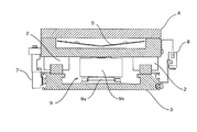
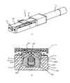
- FIG. 2 is a YY cross-sectional view of FIG. 1 which is an embodiment of the present invention. It is a figure which shows the result of having calculated about three types of cross-sectional shapes using the cross-section secondary moment calculation function of CAD (computer design support tool). It is a figure which shows the upper surface cover of the linear guide bearing apparatus of a prior art, (a) is the perspective view, (b) is II sectional drawing of (a).
- the linear motion guide bearing device 1 allows the mover 4 to move smoothly over the stator 3 and the entire stroke predetermined by the settings of the limit scale 7 and the limit sensor 8.
- Linear motion guide bearings 2 and 2 using rollers as rolling elements are provided on both sides of the mover 4.
- the upper surface cover 5 of the present invention is fixed to the end plates 6 and 6 that are adapted to the shape of the upper surface cover 5 in the state where the upper surface cover 5 is surrounded by the movable element 4, and covers the entire stroke of the movable element 4. Cover.
- the upper surface cover 5 has a shape in a cross section perpendicular to the axial direction of the linear motion guide bearing device 1, and the center portion in the axial direction of the flat plate is bent into a V-shape (non-flat plate), but as will be described later.
- V-shape non-flat plate
- a linear motor is arranged in the center as the drive mechanism 9 for linearly moving the mover 4 with respect to the stator 3, and the stator 3 is connected to the stator side drive mechanism 9 a, and the mover 4 shows an example in which a mover side drive mechanism 9b is connected and the mover 4 is moved with respect to the stator 3 by a desired operation using a linear motor.
- the linear motor is not limited to a linear motor, and a linear motion guide bearing device that is driven by a ball screw or a belt shown in FIG.
- the roller for the rolling element of the linear guide bearing 2 was illustrated in embodiment, it is not restricted to this, You may use a ball
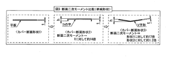
- FIG. 3 shows the results of calculation for three types of cover cross-sectional shapes using the cross-sectional secondary moment calculation function of CAD (Computer Design Support Tool).
- CAD Computer Design Support Tool
- the required width of the cover material before bending is only 1-2% for the V shape and 17% for the U shape. It has been found that the secondary moment of the cross section can be increased by about 14 times (calculation result) only by increasing.
- the non-flat plate shape is very effective in suppressing the deflection due to the weight of the cover as the cover shape of the linear motion guide bearing device in which the cover thickness is limited. It can be said. Furthermore, by using a V-shape with an open top surface and using the top cover as the top surface, foreign matter (dust, bolts, tools, etc.) that has fallen on the cover is prevented from entering the linear motion guide bearing device. In addition to the effect of reducing the number of failures of the apparatus, it is possible to easily collect them on the upper surface of the cover and to facilitate the collection.
- top cover when the top cover is V-shaped, it is easy for foreign matter, particularly dust, etc., to collect on the top surface of the cover as described above. In some cases, an extra load is applied to the cover and the cover is bent. Since it can also be a cause, it is desirable to use it selectively with the U-shaped cover shown in (b) in consideration of the environment used as a linear motion guide bearing device.
Landscapes
- Engineering & Computer Science (AREA)
- General Engineering & Computer Science (AREA)
- Mechanical Engineering (AREA)
- Bearings For Parts Moving Linearly (AREA)
Abstract
Description
この部分の改善の先行技術としては、特許文献1があり、これには図4(a)斜視図に示すように、スライド部(可動子)11が移動するストロークに亘る上面カバー39を端板41、41に取り付け、スライド部(可動子)11を駆動モータ17で駆動する直動案内軸受装置が開示されている。
また、本発明の一態様に係る直動案内軸受装置は、上記上面カバーが、上記直動案内軸受装置の軸方向と垂直な断面において、Vの字形状であり可動方向にV字の谷がありカバーが最上面にある。
また、本発明の一態様に係る直動案内軸受装置は、上記上面カバーが、上記直動案内軸受装置の軸方向と垂直な断面において、コの字形状である。
また、本発明の一態様に係る搬送装置は、上記直動案内軸受装置を備えている。
さらに、本発明の一態様に係る工作機械は、上記直動案内軸受装置を備えている。
なお、この実施形態では、固定子3に対し可動子4を直線移動させる駆動機構9として、リニアモータを中央に配置し、固定子3には、固定子側駆動機構9aが連結され、可動子4には、可動子側駆動機構9bが連結され、固定子3に対して可動子4を所望する動作で移動させるのをリニアモータを使用して行う一例を示しているが、駆動機構は、リニアモータに限るものではなく、従来技術として図4に示したボールねじや、ベルト等で駆動する直動案内軸受装置とすることができる。また実施形態では、直動案内軸受2の転動体にローラーを使用したものを例示したが、これに限るものではなく、玉(ボール)を用いても良い。
2 直動案内軸受
3 固定子
4 可動子
4a 可動子内周下面
4b 可動子内周上面
5 上面カバー
6 端板
7 リミットスケール
8 リミットセンサ
9 駆動機構
9a 駆動機構(固定子側)
9b 駆動機構(可動子側)
10 永久磁石
10a 磁石ホルダ
10b 固定ボルト
11 スライド部(可動子)
17 駆動モータ
21 ガイドレール(固定子)
21c ガイドレール内周面
21d ガイドレール側ボール溝
23 移動体(可動子)
23c 移動体側面
23d 移動体側ボール溝
25 ボール螺子軸
39 上面カバー
41 端板
51 ボール
Claims (5)
- 基台となりうる固定子と、負荷物を搭載可能な可動子と、前記固定子に対し前記可動子を直線上に所定のストローク分移動可能なように案内する直動案内軸受と、前記固定子に対し前記可動子を直線移動させることが可能な駆動機構からなり、
固定子に備える上面カバーが、上記直動案内軸受装置の軸方向と垂直な断面にて非平板形状である直動案内軸受装置。 - 前記上面カバーが、前記直動案内軸受装置の軸方向と垂直な断面において、Vの字形状であり可動方向にV字の谷がありカバーが最上面にある請求項1記載の直動案内軸受装置。
- 前記上面カバーが、前記直動案内軸受装置の軸方向と垂直な断面において、コの字形状である請求項1記載の直動案内軸受装置。
- 請求項1又は2記載の直動案内軸受装置を備えた搬送装置。
- 請求項1又は2記載の直動案内軸受装置を備えた工作機械。
Priority Applications (2)
| Application Number | Priority Date | Filing Date | Title |
|---|---|---|---|
| DE212015000048.6U DE212015000048U1 (de) | 2014-01-15 | 2015-01-14 | Linearführungsvorrichtung, Transportvorrichtung und Werkzeugmaschine |
| JP2016600068U JP3208694U (ja) | 2014-01-15 | 2015-01-14 | 搬送装置 |
Applications Claiming Priority (2)
| Application Number | Priority Date | Filing Date | Title |
|---|---|---|---|
| JP2014005025 | 2014-01-15 | ||
| JP2014-005025 | 2014-01-15 |
Publications (1)
| Publication Number | Publication Date |
|---|---|
| WO2015107886A1 true WO2015107886A1 (ja) | 2015-07-23 |
Family
ID=53542783
Family Applications (1)
| Application Number | Title | Priority Date | Filing Date |
|---|---|---|---|
| PCT/JP2015/000126 Ceased WO2015107886A1 (ja) | 2014-01-15 | 2015-01-14 | 直動案内軸受装置、搬送装置及び工作機械 |
Country Status (3)
| Country | Link |
|---|---|
| JP (1) | JP3208694U (ja) |
| DE (1) | DE212015000048U1 (ja) |
| WO (1) | WO2015107886A1 (ja) |
Citations (3)
| Publication number | Priority date | Publication date | Assignee | Title |
|---|---|---|---|---|
| JP2001116042A (ja) * | 1999-10-15 | 2001-04-27 | Kuroda Precision Ind Ltd | 直動案内機構 |
| JP2012031876A (ja) * | 2010-07-28 | 2012-02-16 | Nsk Ltd | 直動案内軸受装置 |
| JP2012041972A (ja) * | 2010-08-18 | 2012-03-01 | Nsk Ltd | 直動案内軸受装置 |
Family Cites Families (1)
| Publication number | Priority date | Publication date | Assignee | Title |
|---|---|---|---|---|
| JP2001011604A (ja) | 1998-10-16 | 2001-01-16 | Fujitsu Ltd | アルミナ膜およびその製造方法、ならびにアルミナ膜を用いた磁気ヘッド及びその製造方法、ならびに磁気記憶装置及びその製造方法 |
-
2015
- 2015-01-14 WO PCT/JP2015/000126 patent/WO2015107886A1/ja not_active Ceased
- 2015-01-14 DE DE212015000048.6U patent/DE212015000048U1/de not_active Expired - Lifetime
- 2015-01-14 JP JP2016600068U patent/JP3208694U/ja not_active Expired - Lifetime
Patent Citations (3)
| Publication number | Priority date | Publication date | Assignee | Title |
|---|---|---|---|---|
| JP2001116042A (ja) * | 1999-10-15 | 2001-04-27 | Kuroda Precision Ind Ltd | 直動案内機構 |
| JP2012031876A (ja) * | 2010-07-28 | 2012-02-16 | Nsk Ltd | 直動案内軸受装置 |
| JP2012041972A (ja) * | 2010-08-18 | 2012-03-01 | Nsk Ltd | 直動案内軸受装置 |
Also Published As
| Publication number | Publication date |
|---|---|
| JP3208694U (ja) | 2017-02-09 |
| DE212015000048U1 (de) | 2016-08-18 |
Similar Documents
| Publication | Publication Date | Title |
|---|---|---|
| JP6480905B2 (ja) | ロボットハンド | |
| EP1768131B1 (en) | Xy guide table | |
| KR102386019B1 (ko) | 리니어 모듈 및 그 작동 방법 | |
| US9285021B2 (en) | Linear module with a support device | |
| WO2015098122A1 (ja) | 直動案内軸受装置、搬送装置及び工作機械 | |
| JP5739205B2 (ja) | クロスローラ有限直動案内ユニット | |
| EP2674995A1 (en) | Moving mechanism, electronic component transport device, electronic component inspection device | |
| KR101992638B1 (ko) | 개선된 방진 구조를 갖는 리니어 액추에이터 | |
| JP3208694U (ja) | 搬送装置 | |
| JP2012031876A (ja) | 直動案内軸受装置 | |
| JP2012067838A (ja) | 直動案内装置の仮軸用アタッチメント | |
| WO2018092260A1 (ja) | コンベア駆動装置および加工材の排出装置 | |
| KR20130038714A (ko) | 대형 볼스크류의 처짐 방지장치 | |
| JP2012041972A (ja) | 直動案内軸受装置 | |
| JP2012077773A (ja) | 直動案内軸受装置 | |
| KR20120067239A (ko) | 벨트를 이용한 단축로봇 | |
| JP2006231380A (ja) | フレキシブルストレッチ型およびこれを用いたストレッチ成形装置 | |
| JP6290130B2 (ja) | 昇降装置 | |
| JP5942976B2 (ja) | 加工装置及び曲げ加工方法 | |
| JP2009038909A (ja) | アクチュエータにおける原点出し方法およびアクチュエータにおける原点出しストッパ装置 | |
| KR20090124723A (ko) | 리니어 액추에이터의 실링장치 | |
| JP2012143802A (ja) | プレスブレーキ | |
| JP2009102101A (ja) | パレット搬送装置 | |
| JP5931486B2 (ja) | ベンディングロール | |
| CN106573402A (zh) | 可动压盘支撑设备、可动压盘、模具打开/关闭设备和成型设备 |
Legal Events
| Date | Code | Title | Description |
|---|---|---|---|
| 121 | Ep: the epo has been informed by wipo that ep was designated in this application |
Ref document number: 15736997 Country of ref document: EP Kind code of ref document: A1 |
|
| DPE1 | Request for preliminary examination filed after expiration of 19th month from priority date (pct application filed from 20040101) | ||
| ENP | Entry into the national phase |
Ref document number: 2016600068 Country of ref document: JP Kind code of ref document: A |
|
| WWE | Wipo information: entry into national phase |
Ref document number: 212015000048 Country of ref document: DE |
|
| 122 | Ep: pct application non-entry in european phase |
Ref document number: 15736997 Country of ref document: EP Kind code of ref document: A1 |