WO2015107652A1 - ベイナイト組織を有する配管の余寿命を検量線を用いて推定する方法 - Google Patents
ベイナイト組織を有する配管の余寿命を検量線を用いて推定する方法 Download PDFInfo
- Publication number
- WO2015107652A1 WO2015107652A1 PCT/JP2014/050681 JP2014050681W WO2015107652A1 WO 2015107652 A1 WO2015107652 A1 WO 2015107652A1 JP 2014050681 W JP2014050681 W JP 2014050681W WO 2015107652 A1 WO2015107652 A1 WO 2015107652A1
- Authority
- WO
- WIPO (PCT)
- Prior art keywords
- pipe
- outer diameter
- calibration curve
- crack
- remaining life
- Prior art date
- Legal status (The legal status is an assumption and is not a legal conclusion. Google has not performed a legal analysis and makes no representation as to the accuracy of the status listed.)
- Ceased
Links
Images







Classifications
-
- G—PHYSICS
- G01—MEASURING; TESTING
- G01N—INVESTIGATING OR ANALYSING MATERIALS BY DETERMINING THEIR CHEMICAL OR PHYSICAL PROPERTIES
- G01N25/00—Investigating or analyzing materials by the use of thermal means
- G01N25/16—Investigating or analyzing materials by the use of thermal means by investigating thermal coefficient of expansion
Definitions
- the present invention relates to a method for estimating the remaining life of a pipe having a bainite structure using a calibration curve.
- Metal piping such as power steam piping used in thermal power generation facilities and nuclear power generation facilities is subject to high-temperature and high-pressure conditions for a long period of time, so plastic deformation gradually progresses and breaks when the creep life is reached. End up. Therefore, in order to safely and economically operate thermal power generation facilities and nuclear power generation facilities, it is required to accurately predict the remaining creep life.
- a method for estimating the remaining life of a metal pipe As a method for estimating the remaining life of a metal pipe, a method is known in which a calibration curve representing the relationship between the progress of creep damage and the remaining life is prepared and the remaining life is estimated based on this. For example, in Patent Document 1, a bending moment acting on a bend portion is calculated by measuring deformation amounts at a plurality of positions before and after the bend portion (maximum damage site) of a steam pipe, and bending of the bend portion of the pipe obtained in advance is calculated. It is described that the creep damage of the bend portion is obtained from the relationship between the moment and the creep damage.
- the mechanism of creep damage differs depending on the metal structure.
- the damage mechanism is not well understood, and there is no established method for estimating the remaining life. For this reason, it is difficult to know the proper repair and replacement timing of piping.
- the present invention has been made in view of such circumstances, and an object thereof is to provide a method for estimating the remaining life of a pipe having a bainite structure using a calibration curve.
- the present invention is a method for estimating the remaining life of a cylindrical pipe having a bainite structure, which is creep-damaged by heating and pressurization, using a calibration curve.
- a calibration curve showing the relationship between the pipes, and measuring the outer diameter of the pipe to obtain a bulge rate in the diameter direction of the pipe, and based on the bulge rate of the pipe and the calibration curve, The remaining life is estimated.
- the outer diameter of the test specimen is a maximum value of the outer diameter measured a plurality of times from different directions, and the outer diameter of the pipe was measured a plurality of times from different directions. It is the maximum value of the outer diameter of the pipe.
- the bulging rate of the test specimen is the outer diameter of the test specimen after applying the heat and internal pressure to the outer diameter of the test specimen before applying the heat and internal pressure. It is a ratio of diameters.
- the bulging rate of the test specimen of the pipe is the ratio of the outer diameter after the addition to the outer diameter before applying heat and internal pressure, so that the parameter does not depend on the length of the initial outer diameter of the pipe. Is obtained. Therefore, the calibration curve created based on such parameters can be used to estimate the remaining life of pipes with different sizes (different outer diameters) from the test specimen. A calibration curve can be applied.
- Another aspect of the present invention is that when measuring the outer diameter of the test body, it is also determined whether or not a crack has occurred in the test body, and when it is determined that a crack has occurred. Measures the length of the crack having the maximum length among the generated cracks, and shows another calibration curve indicating the relationship between the measured crack length of the specimen and the remaining life of the specimen.
- the remaining life of a pipe having a bainite structure can be estimated using a calibration curve.
- FIG. 2 is a diagram illustrating the configuration of a test body 10. It is a figure explaining the test conditions of an internal pressure creep test. It is a figure which shows the measurement result of an outer diameter, and the calculation result of a bulging rate. It is a graph of the calibration curve showing the relationship between the bulging rate and the life ratio. It is a figure explaining the measurement location of the outer diameter of piping of an actual machine. It is a flowchart which shows the procedure which produces a calibration curve by performing the internal pressure creep test to the test body.
- FIG. 2 is a diagram illustrating the configuration of a test body 10. It is a figure explaining the test conditions of an internal pressure creep test. It is a figure which shows the measurement result of the outer diameter of the test body a. It is a figure which shows the measurement result of the maximum crack length of the test body a. It is a SEM photograph of the test body a in the 6th halfway stop. It is a figure which shows the measurement result of the outer diameter of the test body b. It is a figure which shows the measurement result of the maximum crack length of the test body b. It is a graph of the calibration curve showing the relationship between the bulging rate and the life ratio. It is a graph of the calibration curve showing the relationship between the maximum crack length and the life ratio.
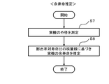
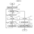
- First Embodiment> 1A and 1B are flowcharts illustrating a method for estimating the remaining life of a pipe according to the first embodiment.
- a calibration curve is created by performing an internal pressure creep test on a test body that simulates piping (FIG. 1A), and then the remaining life of the piping is estimated based on the calibration curve (FIG. 1B).
- the internal pressure creep test is a test for confirming creep damage by heating a test body to which an internal pressure is applied. The remaining life estimation method will be described below with reference to these flowcharts.
- FIG. 2 is a diagram for explaining the configuration of this test body.
- the test body 10 is made of a steel material and includes a hollow substantially cylindrical tube member 11, a first plug member 12, and a second plug member 13.
- Both ends of the tube member 11 are sealed with a first plug member 12 and a second plug member 13, and an injection tube 14 is inserted into the first plug member 12 from the outside.
- the injection tube 14 is a tube for injecting a high-temperature fluid 15 described later into the tube member 11. For this reason, the inside of the tube member 11 and the inside of the injection tube 14 are in communication with each other.
- the material of the pipe member 11 is a material that has a bainite structure and that undergoes creep damage due to heating and pressurization, and is made of the same material as the piping whose remaining life is to be estimated.
- chromium molybdenum steel is used.
- the shape of the pipe member 11 is a cylindrical shape because it simulates piping. However, from the viewpoint of facilitating handling, a metal pipe having a smaller diameter than the pipe is used. As shown in FIG. 3, the diameter phi 10 of the test body 10 (tube member 11) is 56.5 mm.
- the test body 10 has a heating furnace (not shown) in a state where the longitudinal direction of the tube member 11 is substantially horizontal so that the high-temperature fluid 15 injected into the tube member 11 is uniformly accumulated in the tube member 11. ) In the interior space.
- a high-temperature fluid 15 such as water vapor is injected into the injection tube 14
- the high-temperature fluid 15 flows into the hollow portion in the tube member 11, and the test body 10 receives a stress in the diametrical direction, and its internal pressure increases.
- the temperature of the test body 10 also rises. Thus, creep damage is caused to the pipe member 11 by heating and pressurizing the pipe member 11.
- the heating temperature of the test body 10 is not particularly limited as long as the tube member 11 has a bainite structure, but is, for example, in the range of 210 ° C. to 550 ° C., and more preferably in the range of 350 ° C. to 550 ° C. Moreover, it is preferable that it is close to the temperature of the fluid (steam etc.) which distribute
- the range of the pressure applied to the test body 10 is not particularly limited as long as it is higher than the normal pressure (0.1 MPa), but is, for example, 0.2 MPa to 1000 MPa. Further, it is more preferably 0.3 MPa to 500 MPa, and further preferably 0.5 MPa to 300 MPa.
- the tube member 11 is continuously heated and pressurized, and a predetermined time interval (500 hours to 2000 hours, about 1000 hours on average) is kept until the test body 10 breaks.
- the outer diameter that is, the outer diameter of the tube member 11 is measured.
- the portion (the tube member 11, the first plug member 12, and the second plug member 13) excluding the injection tube 14 in the test body 10 has an axial length of 385 mm.
- the measurement position of the outer diameter of the test body 10 is a cross section 16 (P) at a position spaced 195 mm in the axial direction from one end on the first plug member 12 side and 190 mm in the axial direction from one end on the second plug member 13 side. -Q cross section).
- the pipe member 11 was a pipe made of chromium molybdenum steel (STPA 22, JIS standard G 3457 “arc welded carbon steel pipe for piping”).
- the measurement of the outer diameter of the test body 10 is performed by measuring the length of the outer diameter in the first direction (outer diameter ⁇ 1 ) in the cross section 16 and the outer diameter in the second direction perpendicular to the first direction (outer diameter).
- the length of the diameter ⁇ 2 ) was measured, and the maximum value of these was taken as the measured value of the outer diameter.
- the number of times of measurement of the outer diameter at each measurement timing may be any number, and the measurement direction of the outer diameter may be an arbitrary direction instead of a perpendicular direction.
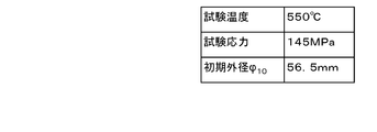
- the heating temperature of the test body 10 was 550 degreeC, and the internal pressure of the test body 10 was 145 MPa.
- outer diameter (phi) 10 maximum value of outer diameter (phi) 1 and outer diameter (phi) 2 ) of the test body 10 before a test was 56.5 mm.
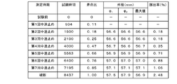
- the test result of this internal pressure creep test is shown in FIG.
- the outer diameter of the test body 10 is measured after 1500 hours (second suspension), after 2100 hours (third suspension), and 4000 hours after the start of applying heat and internal pressure ( 4th stop), after 5563 hours (5th stop), 6400 hours (6th stop), 7195 hours (7th stop), and 8437 hours (breakage of specimen 10) Time).
- the life ratio at the second halfway stop (heating and pressing time / breaking time) is 0.18, the life ratio at the third halfway stop is 0.25, and the fourth halfway stop.
- the life ratio at 0.45, the life ratio at the 5th stop is 0.66, the life ratio at the 6th stop is 0.76, and the life ratio at the 7th stop is 0.85
- the life ratio at break is 1.00.
- the swelling rate of the test body 10 obtained from the measured value of the outer diameter is 0.18% at the second halfway stop, 0.18% at the third halfway stop, 0.35% at the fourth halfway stop, It is 0.71% at the fifth break, 0.88% at the sixth break, 1.06% at the seventh break, and 2.48% at break.
- these swelling rates were calculated
- FIG. 5 is a calibration curve graph created based on the above measurement results and showing the relationship between the life ratio and the bulging rate.
- the outer diameter of the actual pipe is measured (S7).
- the length of the outer diameter in the first direction (outer diameter ⁇ 30A ) and the length of the outer diameter in the second direction (outer diameter ⁇ 30B ) orthogonal to the first direction are measured, and the larger one is the pipe 30. Obtained as the outer diameter value of.
- the outer diameter value is acquired before operation (before heating and pressurization) and during operation (during regular inspection, etc.).
- the number of times of measurement of the outer diameter is not limited to two as in this example, and may be any number, and the measurement direction of the outer diameter is not a perpendicular direction but may be an arbitrary direction.
- the remaining life of the pipe is estimated based on the measured value of the outer diameter and the calibration curve created in S6 (S8 in FIG. 1B). That is, the bulging rate is calculated based on the initial outer diameter value of the pipe 30 before operation and the outer diameter value of the pipe 30 during operation. Then, the calculated bulging rate is applied to a calibration curve created with the test body 10.
- the swelling rate was B 1 represents, calibration curve 21 the life ratio of the time of the bulging ratio is B, ie L 1 becomes life ratio.
- the outer diameter of the test body 10 swelled in the diametric direction is obtained by performing an internal pressure creep test in which the pipe test body 10 is heated and an internal pressure is applied.
- this bulge amount is the length of the initial outer diameter of the pipe.
- This parameter does not depend on. Therefore, the calibration curve created based on such parameters can also be used to estimate the remaining life of piping having a different size (different outer diameter) from that of the specimen. For example, this calibration curve can be applied to an actual machine larger than the test body 10.
- Second Embodiment The present inventors have found that when a pipe having a bainite structure is cracked, the length of the crack having the maximum length among the cracks is correlated with the remaining life. Therefore, the present inventors create a calibration curve related to the relationship between the maximum length of cracks and the remaining life in addition to the calibration curve related to the relationship between the bulging amount and the remaining life as described in the first embodiment, A method for estimating the remaining life of piping using these two calibration curves was conceived.
- FIG. 7A and 7B are flowcharts showing the remaining life estimation method according to the present embodiment.
- FIG. 7A is a flowchart which shows the procedure which produces a calibration curve.
- FIG. 7B is a flowchart showing a procedure for estimating the remaining life of the pipe based on the calibration curve.
- the second embodiment in addition to the measurement of the outer diameter described in the first embodiment, it is determined whether or not a crack has occurred on the surface of the test body 10. And when the crack has generate
- test body 10 has cracks is determined by, for example, observing the structure with a scanning electron microscope (SEM). This tissue observation is performed on a predetermined range in the test body 10, for example, a predetermined range at a position where the outer diameter is measured (for example, the central portion in the axial direction). Further, the width of the predetermined range is arbitrary, but is, for example, 0.3 mm 2 to 1.0 mm 2 .
- test body a and test body b having different outer diameters.
- the test using the test specimen a is a test using the same test specimen 10 as in the first embodiment.
- the test by the test body b is a test by the test body 10 having an initial outer diameter ⁇ 10 of 56.6 mm.
- the test conditions are a heating temperature of 550 ° C. and an internal pressure of 145 MPa.
- FIG.10 and FIG.11 is the figure which put together the test result of the test body a.
- FIG. 10 shows the measurement result of the outer diameter, which is the same as FIG.
- FIG. 11 is a diagram showing the results of the maximum crack length of the test body a.
- the occurrence of cracks in the test specimen a was confirmed at the sixth stop (6400 hours later), after 7195 hours (seventh stop), and when the test specimen a was broken ( 8437 hours later), and the maximum crack lengths measured at that time were 518 ⁇ m, 1.09 mm, and 18.1 mm, respectively.
- the bulging rate of the specimen a is the same as in the first embodiment (0.18% for the second halfway stop, 0.18% for the third halfway stop, and 0.35 for the fourth halfway stop. %, 0.71% at the 5th stop, 0.88% at the 6th stop, 1.06% at the 7th stop, 2.48% at break).
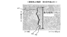
- FIG. 12 shows an SEM image of the specimen a at the time of the sixth suspension.
- the test body a has cracks 41 and 42, but the gap between the cracks 41 and 42 is broken.
- the length of the cut portion is predetermined with respect to the longer length of both cracks adjacent to the cut portion. If the ratio is less than or equal to the above, the crack length was determined by regarding that both cracks and the cut-off portion were one connected crack.
- the predetermined ratio is preferably, for example, half, more preferably 40%, and still more preferably 30%.
- the crack 41 and the crack 42 include the cut portion.
- the crack length was 518 ⁇ m.
- the length of the crack is the length of a straight line connecting both ends of the crack, and the length of the part that is cut off is formed by the part that is cut off and the two cracks adjacent to the cut part.
- the method of measuring the length of a crack is not specifically limited, A well-known method can be used, For example, it measures by performing surface structure
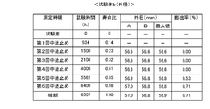
- FIG. 13 shows the measurement result of the outer diameter of the specimen b.
- the measurement of the outer diameter of the test specimen b is 1500 hours after the start of application of heat and internal pressure (second suspension), 2100 hours (third suspension), and 4000 hours later ( 4th stoppage), after 5562 hours (5th stoppage), after 6400 hours (6th stoppage), and after 6507 hours (when the specimen b was broken).
- the bulging rate calculated from these outer diameters is 0.00% for the second halfway stop, 0.00% for the third halfway stop, 0.00% for the fourth halfway stop, and the fifth halfway. It was 0.53% at the stop, 0.71% at the sixth stop, and 0.71% at break.
- the life ratio at the second halfway stop is 0.23
- the life ratio at the third halfway stop is 0.32
- the fourth The life ratio at the middle stop is 0.61
- the life ratio at the fifth halfway stop is 0.85
- the life ratio at the sixth halfway stop is 0.98
- the life ratio at break is 1.00. is there.
- FIG. 14 shows the measurement result of the maximum crack length of the specimen b.
- the maximum crack length after 5562 hours from the start of the test (fifth stop) is 764 ⁇ m
- the maximum crack length after 6400 hours from the start of the test is 3.41 mm.
- the maximum crack length at the time of rupture was 23.7 mm.
- the measurement interval of the outer diameter and the maximum crack length of the specimen b is about 500 hours to about 2000 hours as in the first embodiment, and averages about 1000 hours. is there.
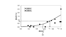
- FIG. 15 is a calibration curve 51 created based on the above test results and showing the relationship between the bulging rate and the life ratio. As shown in the figure, the calibration curve 51 is exponentially approximated so as to pass through the origin.
- FIG. 16 is a calibration curve 61 showing the relationship between the maximum crack length and the life ratio calibration curve. As shown in the figure, exponential approximation was performed so that the calibration curve 61 also passes through the origin.
- the maximum crack length of the actual pipe is measured (S22). Specifically, for example, the maximum crack length in the range where the structure is observed in S21 is measured.
- the measured maximum crack length is fitted to a calibration curve 61 indicating the relationship between the maximum crack length and the life ratio calibration curve (S23), and the remaining life of the pipe is estimated (S24).
- the maximum crack length in actual use is a C 3
- the life ratio of the calibration curve 61 at the maximum crack length is C3, i.e. L 3 becomes life ratio.
- the outer diameter of the actual machine pipe is measured (S25). For example, the outer diameter of the central part of a pipe that is susceptible to creep damage is measured.
- the measured outer diameter is applied to a calibration curve 51 representing the relationship between the bulging rate and the life ratio (S26), and the remaining life of the pipe is estimated (S27).
- the bulging rate is obtained from the measured outer diameter value, and a bulging rate-life ratio calibration curve is created from the obtained bulging rate to obtain the life ratio of the pipe.
- the actual bulging ratio is B 2
- bulging rate life ratio of the calibration curve 51 when the B 2 i.e. L 2 is life ratio.
- a calibration curve representing the relationship between the maximum crack length and the remaining life is prepared, and if a crack has occurred in the pipe, the maximum crack length is By estimating the remaining life of the pipe based on the calibration curve representing the relationship between the life and the remaining life and the actual measured value of the maximum crack length, it is possible to accurately estimate the remaining life of the pipe having the bainite structure.
Landscapes
- Physics & Mathematics (AREA)
- Health & Medical Sciences (AREA)
- Life Sciences & Earth Sciences (AREA)
- Chemical & Material Sciences (AREA)
- Analytical Chemistry (AREA)
- Biochemistry (AREA)
- General Health & Medical Sciences (AREA)
- General Physics & Mathematics (AREA)
- Immunology (AREA)
- Pathology (AREA)
- Testing Resistance To Weather, Investigating Materials By Mechanical Methods (AREA)
- Investigating Strength Of Materials By Application Of Mechanical Stress (AREA)
Abstract
本発明の目的は、ベイナイト組織を有する配管の余寿命を推定することにある。 本発明は、加熱及び加圧によりクリープ損傷を受ける、ベイナイト組織を有する円筒形状の配管の余寿命を検量線を用いて推定する方法である。本発明では、材質が配管と同一の、中空の試験体10に熱及び内圧を加えて外径を測定し、所定時間をおいて外径の測定を複数回行うことにより、試験体10の直径方向の膨出率と試験体10の余寿命との関係を示す検量線を作成する。その後、配管の外径を測定し、配管の直径方向の膨出率と前述の検量線とに基づき、配管の余寿命を推定する。
Description
本発明は、ベイナイト組織を有する配管の余寿命を検量線を用いて推定する方法に関する。
火力発電設備や原子力発電設備等において用いられる動力用蒸気配管などの金属配管は、長期間に渡って高温・高圧条件におかれることから、徐々に塑性変形が進み、クリープ寿命に達すると破断してしまう。従って、火力発電設備や原子力発電設備を安全かつ経済的に運転するためには、クリープ余寿命を的確に予測することが求められる。
金属配管の余寿命を推定する方法としては、クリープ損傷の進行と余寿命との関係を表す検量線を作成しておき、これに基づいて余寿命を推定する手法が知られている。例えば特許文献1には、蒸気配管のベンド部(最大損傷部位)前後の複数の位置において変形量を測定することによりベンド部に働く曲げモーメントを計算し、予め求めてある配管のベンド部の曲げモーメントとクリープ損傷との関係から、ベンド部のクリープ損傷を求めることが記載されている。
ただ、クリープ損傷のメカニズムは金属組織によって異なっている。特に、炭素鋼を所定条件下で冷却した場合にのみ得られるベイナイト組織を有する鉄鋼配管については、その損傷メカニズムがよく分かっておらず、確立された余寿命の推定方法がない。そのため、適切な配管の補修、交換タイミングを知ることが難しくなっている。
本発明はこのような事情に鑑みてなされたものであり、その目的は、ベイナイト組織を有する配管の余寿命を検量線を用いて推定する方法を提供することにある。
本発明者らは、ベイナイト組織を有する配管のクリープ損傷のメカニズムについて研究を重ねた結果、ベイナイト組織を有する配管は加熱及び加圧によって直径方向に膨出し、この膨出率が余寿命判断の適切な指標になり得ること、また、ベイナイト組織を有する配管に亀裂が発生している場合はその亀裂の最大の長さが余寿命と相関関係にあることを見出し、本発明を完成するに至った。
すなわち、本発明は、加熱及び加圧によりクリープ損傷を受ける、ベイナイト組織を有する円筒形状の配管の余寿命を検量線を用いて推定する方法であって、材質が前記配管と同一の、中空の試験体に熱及び内圧を加えて外径を測定し、所定時間をおいて前記外径の測定を複数回行うことにより、前記試験体の直径方向の膨出率と前記試験体の余寿命との関係を示す検量線を作成し、前記配管の外径を測定することで、前記配管の直径方向の膨出率を求め、前記配管の膨出率と前記検量線とに基づき、前記配管の余寿命を推定することを特徴とする。
また、本発明の他の一つは、前記試験体の外径は、異なる方向から複数回測定された外径の最大値であり、前記配管の外径は、異なる方向から複数回測定された前記配管の外径の最大値であることを特徴とする。
ベイナイト組織を有する配管では、外径が大きいほどクリープ損傷が進行していると考えられる。そこで、異なる方向から複数回測定した測定値のうち最大値を外径の値とすることで、クリープ損傷による寿命時期を正確に予測することができる。
また、本発明の他の一つは、前記試験体の膨出率は、前記熱及び内圧を加える前の前記試験体の外径に対する、前記熱及び内圧を加えた後の前記試験体の外径の比であることを特徴とする。
このように、配管の試験体の膨出率を、熱及び内圧を加える前の外径に対する、加えた後の外径の比とすることにより、配管の初期外径の長さに依存しないパラメータが得られる。したがって、このようなパラメータに基づき作成した検量線は、試験体とサイズの異なる(外径の異なる)配管の余寿命推定にも用いることができ、例えば試験体より大型の実機に対してもこの検量線を適用することができる。
また、本発明の他の一つは、前記試験体の外径を測定する際には、前記試験体に亀裂が発生しているか否かも判定し、亀裂が発生していると判定した場合には、前記発生している亀裂のうち最大の長さを有する亀裂の長さを測定し、測定した前記試験体の亀裂の長さと前記試験体の余寿命との関係を示す他の検量線を作成し、前記配管の外径を測定する際には、前記配管に亀裂が発生しているか否かも判定し、亀裂が発生している判定した場合には、前記配管に存在する亀裂のうち最大の長さを有する亀裂の長さを測定し、測定した前記配管の亀裂の長さと前記他の検量線とに基づき、前記配管の余寿命を推定することを特徴とする。
このように、試験体について最大の亀裂の長さと余寿命との関係を表す検量線を作成しておき、配管に亀裂が発生している場合は、上記の検量線と、配管の最大亀裂長さの測定値とに基づき配管の余寿命を推定することで、ベイナイト組織を有する配管の余寿命を正確に推定することができる。
本発明によれば、ベイナイト組織を有する配管の余寿命を検量線を用いて推定することができる。
<第1実施形態>
図1A及び図1Bは、第1実施形態に係る配管の余寿命の推定方法を示すフローチャートである。本実施形態では、配管を模擬した試験体に対し、内圧クリープ試験を行うことにより検量線を作成し(図1A)、次にこの検量線に基づき配管の余寿命を推定する(図1B)。なお、内圧クリープ試験とは、内圧を印加した試験体を加熱し、クリープ損傷を確認する試験である。以下、これらのフローチャートに従って、余寿命の推定方法を説明する。
図1A及び図1Bは、第1実施形態に係る配管の余寿命の推定方法を示すフローチャートである。本実施形態では、配管を模擬した試験体に対し、内圧クリープ試験を行うことにより検量線を作成し(図1A)、次にこの検量線に基づき配管の余寿命を推定する(図1B)。なお、内圧クリープ試験とは、内圧を印加した試験体を加熱し、クリープ損傷を確認する試験である。以下、これらのフローチャートに従って、余寿命の推定方法を説明する。
この推定方法では、まず配管の試験体を加熱し、内圧を印加する(S1)。図2は、この試験体の構成を説明する図である。同図に示すように、試験体10は、鋼材で作製され、中空の略円筒形状の管部材11、第1栓部材12、及び第2栓部材13を含んで構成される。
管部材11の両端は、第1栓部材12及び第2栓部材13によって封止されており、このうち第1栓部材12には外部から注入管14が挿入されている。注入管14は、後述する高温流体15を管部材11の内部に注入するための管である。このため、管部材11の内部と注入管14の内部とは互いに連通されている。
管部材11の素材は、ベイナイト組織を有し、かつ、加熱及び加圧によってクリープ損傷を受ける素材であって、余寿命の推定対象となる配管と同一の素材で作製される。本実施形態では、クロムモリブデン鋼が用いられている。管部材11の形状は、配管を模擬していることから円筒形状である。但し、取扱いを容易にする観点から、配管よりも小径の金属管が用いられている。図3に示すように、試験体10(管部材11)の直径φ10は56.5mmである。
この試験体10は、管部材11に注入された高温流体15が管部材11内に万遍なく蓄積されるように、管部材11の長手方向が略水平となる状態で加熱炉(図示せず)の内部空間に設置される。そして、注入管14に水蒸気等の高温流体15を注入すると、高温流体15は管部材11内の空洞部に流入し、試験体10は直径方向の応力を受け、その内圧が上昇する。また、試験体10の温度も上昇する。このように、管部材11を加熱、加圧することにより、管部材11にクリープ損傷を生じさせる。
試験体10の加熱温度は、管部材11がベイナイト組織を有する限り特に限定されないが、例えば210℃~550℃の範囲であり、350℃~550℃の範囲であることがより好ましい。また、余寿命の推定対象となる実機配管に流通する流体(水蒸気等)の温度に近いことが好ましい。試験体10に加える圧力の範囲は、常圧(0.1MPa)よりも高ければ特に限定されないが、例えば0.2MPa~1000MPaである。また、0.3MPa~500MPaであることがより好ましく、0.5MPa~300MPaであることがさらに好ましい。
このように、管部材11を連続的に加熱及び加圧した状態とし、試験体10が破断するまで所定の時間間隔(500時間~2000時間,平均すると約1000時間)をおきながら試験体10の外径、すなわち管部材11の外径を測定していく。
具体的には、図1Aのフローチャートに示すように、試験体10が破断していない場合は(S2:NO)、所定の測定タイミングが到来した時点で(S3:YES)、試験体10の外径を測定する(S4)。試験体10が破断した場合は(S2:YES)、その時点における試験体10の外径を測定し(S5)、後述する膨出率と寿命比の関係を表す検量線の作成に移行する(S6)。
ここで、発明者らが行った内圧クリープ試験について具体的に説明する。
まず、使用した試験体10の寸法等について説明する。図2に示すように、試験体10における注入管14を除いた部分(管部材11、第1栓部材12、第2栓部材13)は、軸方向の長さが385mmである。また、試験体10の外径の測定位置は、第1栓部材12の側の一端から軸方向に195mm、第2栓部材13の側の一端から軸方向に190mm離間した位置における断面16(P-Q断面)とした。このように管部材11の軸方向中央部を外径の測定位置としたのは、かかる位置が最も応力を受け易く、クリープ損傷が起きやすいと考えられるからである。
管部材11には、クロムモリブデン鉄鋼鋼材で作られた配管(STPA22、JIS規格 G 3457「配管用アーク溶接炭素鋼鋼管」)を用いた。
試験体10の外径の測定は、図2に示すように、断面16における第1方向の外径(外径φ1)の長さと、第1方向と直交する第2方向の外径(外径φ2)の長さを測定し、これらのうちの最大値を外径の測定値とした。なお、各測定タイミングにおける外径の測定回数は何回でもよく、また外径の測定方向も直交する方向でなく任意の方向でよい。
また、図3に示すように、試験体10の加熱温度は550℃、試験体10の内圧は145MPaとした。なお、試験前の試験体10の外径φ10(外径φ1と外径φ2の最大値)は56.5mmであった。
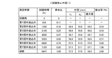
次に、この内圧クリープ試験の試験結果を図4に示す。同図に示すように、試験体10の外径の測定は、熱及び内圧を加え始めてから1500時間後(第2回中途止め)、2100時間後(第3回中途止め)、4000時間後(第4回中途止め)、5563時間後(第5回中途止め)、6400時間後(第6回中途止め)、7195時間後(第7回中途止め)、及び8437時間後(試験体10の破断時)に行った。
なお、上記の試験時間から、第2回中途止めでの寿命比(加熱加圧時間/破断時間)は0.18、第3回中途止めでの寿命比は0.25、第4回中途止めでの寿命比は0.47、第5回中途止めでの寿命比は0.66、第6回中途止めでの寿命比は0.76、第7回中途止めでの寿命比は0.85、破断時の寿命比は1.00と求まる。
外径の測定値から求められる試験体10の膨出率は、第2回中途止めでは0.18%、第3回中途止めでは0.18%、第4回中途止めでは0.35%、第5回中途止めでは0.71%、第6回中途止めでは0.88%、第7回中途止めでは1.06%、破断時では2.48%である。なお、これらの膨出率は、次式(1)に従って求めた。
膨出率(%)=(外径の測定値-初期外径)/初期外径×100・・・(1)
図5は、以上の測定結果に基づき作成された、寿命比と膨出率の関係を表す検量線のグラフである。同図に示すように、この検量線21は、原点((寿命比,膨出率)=(0,0))を通るように指数近似を行った検量線である。
次に、このようにして作成された検量線に基づき配管の余寿命を推定する方法について、図1Bのフローチャートを参照しつつ説明する。
同図に示すように、まず実機の配管の外径を測定する(S7)。例えば、図6に示すように軸方向に所定長さを有する略円筒形の配管30の場合、最も強い応力を受けると思われる軸方向中央部の断面31(R-S)における外径φ30を測定する。この測定でも、第1方向の外径(外径φ30A)の長さと、第1方向と直交する第2方向の外径(外径φ30B)の長さを測定し、大きい方を配管30の外径値として取得する。なお、外径値の取得は、運用前(加熱及び加圧前)及び運用中(定期点検時等)のそれぞれで行う。また、外径の測定回数は本例のように2回に限らず何回でもよく、また外径の測定方向も直交する方向でなく、任意の方向でよい。
次に、外径の測定値とS6で作成した検量線に基づき、配管の余寿命を推定する(図1BのS8)。すなわち、運用前における配管30の初期外径値と運用中における配管30の外径値に基づいて膨出率を算出する。そして、算出した膨出率を試験体10で作成した検量線にあてはめる。図5に示す例では、膨出率がB1であった場合には、膨出率がBの時の検量線21の寿命比、すなわちL1が寿命比となる。
以上に説明したように、本実施形態の余寿命の推定方法では、配管の試験体10を加熱し内圧を加える内圧クリープ試験を行うことにより、直径方向に膨出した試験体10の外径の測定値と寿命比との間の関係を表す検量線を作成することで、ベイナイト組織を有する配管の余寿命を正確に推定することができる。
また、ベイナイト組織を有する配管では、外径が大きいほどクリープ損傷が進行していると考えられることから、異なる方向から複数回測定した測定値のうち最大値を外径の値とすることで、クリープ損傷による寿命時期を正確に予測することができる。
また、配管の試験体10の膨出量を、膨出率(熱及び内圧を加える前の外径値に対する割合)に基づき算出することにより、この膨出量は配管の初期外径の長さに依存しないパラメータとなる。したがって、このようなパラメータに基づき作成した検量線は、試験体とサイズの異なる(外径の異なる)配管の余寿命推定にも用いることができる。例えば試験体10より大型の実機に対してもこの検量線を適用することができる。
<第2実施形態>
本発明者らは、ベイナイト組織を有する配管に亀裂が発生している場合は、その亀裂のうち最大の長さを有する亀裂の長さが、余寿命と相関関係にあることを見出した。そこで、本発明者らは、第1実施形態で説明したような、膨出量と余寿命の関係に係る検量線に加え、亀裂の最大長さと余寿命の関係に係る検量線を作成し、これら2つの検量線を用いて配管の余寿命を推定する方法を着想した。
本発明者らは、ベイナイト組織を有する配管に亀裂が発生している場合は、その亀裂のうち最大の長さを有する亀裂の長さが、余寿命と相関関係にあることを見出した。そこで、本発明者らは、第1実施形態で説明したような、膨出量と余寿命の関係に係る検量線に加え、亀裂の最大長さと余寿命の関係に係る検量線を作成し、これら2つの検量線を用いて配管の余寿命を推定する方法を着想した。
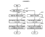
図7A及び図7Bは、本実施形態に係る余寿命の推定方法を示すフローチャートである。このうち図7Aは、検量線を作成する手順を示すフローチャートである。また、図7Bは、検量線に基づき配管の余寿命を推定する手順を示すフローチャートである。
まず、検量線を作成する手順について説明する。図7Aのフローチャートに示すように、検量線を作成するに際し、まず第1実施形態と同様の内圧クリープ試験を行う(S11)。
この第2実施形態では、第1実施形態で説明した外径の測定に加え、試験体10の表面に亀裂が発生しているか否かを判定する。そして、亀裂が発生している場合には、その亀裂の長さを測定する。なお、亀裂が複数発生している場合はその最大値を測定する。便宜上、以下の説明では、1つしか発生していない亀裂の長さと、複数発生している亀裂のうちの最大値とをまとめて「最大亀裂長さ」という。
そして、S12~S16に示すように、試験体10が破断していない限り(S12:NO)、所定の測定タイミングが到来した時点で(S13:YES)、試験体10の外径を測定し(S14)。この際試験体10に亀裂が発生している場合は(S15:YES)、その最大亀裂長さを測定する(S16)。その後はS12に戻る。試験体10が破断した場合は(S12:YES)、その時点で試験体10の外径、及び最大亀裂長さを測定し(S17、S18)、後述する検量線の作成に進む(S19)。
なお、試験体10に亀裂が生じているか否かの判定は、例えば、走査型電子顕微鏡(SEM:Scanning Electron Microscope)による組織観察によって行う。この組織観察は、試験体10における所定の範囲に対して行い、例えば外径を測定した位置(例えば軸方向中央部)における所定範囲とする。また、この所定範囲の広さは任意であるが、例えば0.3mm2~1.0mm2である。
S19では、外径や最大亀裂長さの測定値に基づき、膨出率と寿命比の関係を表す検量線と、最大亀裂長さと寿命比の関係を表す検量線とを作成する。
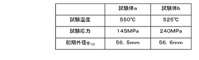
図8及び図9に示すように、第2実施形態では、外径が異なる2つの試験体10(試験体a、試験体b)を用いて内圧クリープ試験を行った。試験体aによる試験は第1実施形態と同じ試験体10による試験である。試験体bによる試験は、初期外径φ10が56.6mmの試験体10による試験であり、この試験条件は、加熱温度が550℃、内圧が145MPaである。
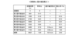
次に、試験結果について説明する。図10及び図11は、試験体aの試験結果をまとめた図である。このうち図10は外径の測定結果であり、図4と同様なので説明を省略する。図11は、試験体aの最大亀裂長さの結果を示す図である。
図11に示すように、試験体aに亀裂の発生が確認されたのは第6回中途止め(6400時間後)、7195時間後(第7回中途止め)、及び試験体aの破断時(8437時間後)であり、その際に測定された最大亀裂長さはそれぞれ、518μm、1.09mm、18.1mmであった。なお、試験体aの膨出率は第1実施形態と同様である(第2回中途止めでは0.18%、第3回中途止めでは0.18%、第4回中途止めでは0.35%、第5回中途止めでは0.71%、第6回中途止めでは0.88%、第7回中途止めでは1.06%、破断時では2.48%)。
図12に、第6回中途止め時における試験体aのSEMの像を示す。同図に示すように、試験体aには亀裂41及び亀裂42が発生しているが、亀裂41及び亀裂42の間が寸断されている。このように、最大亀裂長さの測定範囲において亀裂が寸断されている場合は、寸断されている箇所の長さが、その寸断箇所が隣接する両亀裂のうち長い方の長さに対して所定の割合以下であれば、これら両亀裂及び寸断箇所は繋がった一つの亀裂であるとみなして、亀裂の長さを求めた。
すなわち、亀裂が途中で寸断されている場合、寸断されている箇所が今後亀裂になるか否かは、この寸断箇所が隣接している両亀裂のうち長い方の亀裂から強い影響を受けると考えられる。そして、長い方の長さに対して寸断箇所の長さが所定の割合以下である場合には、この寸断箇所が今後亀裂になりやすいと評価できると考えられる。
そこで、上記のように寸断箇所の長さが亀裂に対して短い場合には寸断箇所をも亀裂の一部とみなすことにより、クリープ余寿命を精度良く予測できる検量線を作成することができると考えられる。このことから、上記所定の割合は、例えば半分であることが好ましく、4割であることがより好ましく、3割であることがさらに好ましい。
図12の例では、寸断されている箇所の長さ43が、亀裂41、亀裂42のうち長い方の亀裂41の長さの半分以下であることから、亀裂41及び亀裂42は寸断箇所も含めて一つの亀裂であるとみなし、その亀裂長さを518μmとした。
なお、亀裂の長さとは、亀裂の両端を結んだ直線の長さであり、また、寸断されている箇所の長さとは、寸断されている箇所とこの寸断箇所が隣接する両亀裂とが作る2つの交点間の直線の長さである。また、亀裂の長さを測定する方法は、特に限定されず、公知の方法を用いることができるが、例えば、走査型電子顕微鏡によって表面の組織観察を行うことによって測定する。
図13には、試験体bの外径の測定結果を示す。同図に示すように、試験体bの外径の測定は、熱及び内圧を加え始めてから1500時間後(第2回中途止め)、2100時間後(第3回中途止め)、4000時間後(第4回中途止め)、5562時間後(第5回中途止め)、6400時間後(第6回中途止め)、及び6507時間後(試験体bの破断時)に行った。これらの外径から算出される膨出率は、第2回中途止めで0.00%、第3回中途止めで0.00%、第4回中途止めで0.00%、第5回中途止めで0.53%、第6回中途止めで0.71%、破断時で0.71%であった。なお、第1実施形態と同様にこれらの測定タイミングにおける寿命比を求めると、第2回中途止めでの寿命比は0.23、第3回中途止めでの寿命比は0.32、第4回中途止めでの寿命比は0.61、第5回中途止めでの寿命比は0.85、第6回中途止めでの寿命比は0.98、破断時の寿命比は1.00である。
図14には、試験体bの最大亀裂長さの測定結果を示す。同図に示すように、試験開始から5562時間後(第5回中途止め)における最大亀裂長さは764μm、試験開始から6400時間後(第6回中途止め)における最大亀裂長さは3.41mm、破断時(試験開始から6507時間後)における最大亀裂長さは23.7mmであった。
なお、図13、図14に示すように、試験体bの外径及び最大亀裂長さの測定間隔は第1実施形態と同様に約500時間~約2000時間であり、平均すると約1000時間である。
図15は、以上の試験結果に基づき作成された、膨出率と寿命比の関係を示す検量線51である。同図に示すように、この検量線51では、原点を通るように指数近似を行った。一方、図16は、最大亀裂長さと寿命比検量線の関係を示す検量線61である。同図に示すように、この検量線61も原点を通るように指数近似を行った。
次に、これら2つの検量線に基づく余寿命の推定手順を、図7Bのフローチャートに参照しつつ説明する。
同図に示すように、余寿命の推定に際しては、まず実機の配管に亀裂が発生しているか否かを判定する(S21)。この亀裂の発生の判定は、例えば、走査型電子顕微鏡(SEM)による組織観察によって行う。組織観察の範囲は、例えば、クリープ損傷を受けやすい部位(例えば配管中央部)に設定した所定範囲(0.3mm2~1.0mm2)とする。
実機の配管に亀裂が発生していると判定した場合には(S21:YES)、実機の配管の最大亀裂長さを測定する(S22)。具体的には、例えばS21で組織観察を行った範囲における最大亀裂長さを測定する。
そして、測定した最大亀裂長さを、最大亀裂長さと寿命比検量線の関係を示す検量線61にあてはめ(S23)、配管の余寿命を推定する(S24)。図16の例では、実機の最大亀裂長さがC3であるので、最大亀裂長さがC3の時の検量線61の寿命比、すなわちL3が寿命比となる。
一方、実機の配管に亀裂が発生していないと判定した場合には(図7BのS21:NO)、実機の配管の外径を測定する(S25)。例えば、クリープ損傷を受けやすい配管中央部の外径を測定する。
そして、測定した外径を、膨出率と寿命比の関係を表す検量線51にあてはめ(S26)、配管の余寿命を推定する(S27)。具体的には、測定した外径値から膨出率を求め、求めた膨出率から膨出率-寿命比検量線を作成して配管の寿命比を求める。図15の例では、実機の膨出率がB2であるので、膨出率がB2の時の検量線51の寿命比、すなわちL2が寿命比となる。
このように、本実施形態の配管の余寿命の推定方法では、最大亀裂長さと余寿命との関係を表す検量線を作成しておき、配管に亀裂が発生している場合は、最大亀裂長さと余寿命との関係を表す検量線と、最大亀裂長さの実測値とに基づき配管の余寿命を推定することで、ベイナイト組織を有する配管の余寿命を正確に推定することができる。
以上の実施形態の説明は、本発明の理解を容易にするためのものであり、本発明を限定するものではない。本発明はその趣旨を逸脱することなく、変更、改良され得ると共に本発明にはその等価物が含まれる。
10 試験体、11 管部材、12 第1栓部材、13 第2栓部材、14 注入管、15 高温流体、16 断面、21 検量線 30 配管、31 断面、41 亀裂、42 亀裂、43 寸断されている箇所の長さ、51 検量線、61 検量線
Claims (4)
- 加熱及び加圧によりクリープ損傷を受ける、ベイナイト組織を有する円筒形状の配管の余寿命を検量線を用いて推定する方法であって、
材質が前記配管と同一の、中空の試験体に熱及び内圧を加えて外径を測定し、
所定時間をおいて前記外径の測定を複数回行うことにより、前記試験体の直径方向の膨出率と前記試験体の余寿命との関係を示す検量線を作成し、
前記配管の外径を測定することで、前記配管の直径方向の膨出率を求め、
前記配管の膨出率と前記検量線とに基づき、前記配管の余寿命を推定することを特徴とする、ベイナイト組織を有する配管の余寿命を検量線を用いて推定する方法。 - 前記試験体の外径は、異なる方向から複数回測定された外径の最大値であり、
前記配管の外径は、異なる方向から複数回測定された前記配管の外径の最大値であることを特徴とする、請求項1に記載のベイナイト組織を有する配管の余寿命を検量線を用いて推定する方法。 - 前記試験体の膨出率は、前記熱及び内圧を加える前の前記試験体の外径に対する、前記熱及び内圧を加えた後の前記試験体の外径の比であることを特徴とする、請求項1又は2に記載のベイナイト組織を有する配管の余寿命を検量線を用いて推定する方法。
- 前記試験体の外径を測定する際には、前記試験体に亀裂が発生しているか否かも判定し、亀裂が発生していると判定した場合には、
前記発生している亀裂のうち最大の長さを有する亀裂の長さを測定し、
測定した前記試験体の亀裂の長さと前記試験体の余寿命との関係を示す他の検量線を作成し、
前記配管の外径を測定する際には、前記配管に亀裂が発生しているか否かも判定し、亀裂が発生している判定した場合には、
前記配管に存在する亀裂のうち最大の長さを有する亀裂の長さを測定し、
測定した前記配管の亀裂の長さと前記他の検量線とに基づき、前記配管の余寿命を推定することを特徴とする、請求項1乃至3のいずれか一項に記載のベイナイト組織を有する配管の余寿命を検量線を用いて推定する方法。
Priority Applications (2)
| Application Number | Priority Date | Filing Date | Title |
|---|---|---|---|
| PCT/JP2014/050681 WO2015107652A1 (ja) | 2014-01-16 | 2014-01-16 | ベイナイト組織を有する配管の余寿命を検量線を用いて推定する方法 |
| JP2015512419A JPWO2015107652A1 (ja) | 2014-01-16 | 2014-01-16 | ベイナイト組織を有する配管の余寿命を検量線を用いて推定する方法 |
Applications Claiming Priority (1)
| Application Number | Priority Date | Filing Date | Title |
|---|---|---|---|
| PCT/JP2014/050681 WO2015107652A1 (ja) | 2014-01-16 | 2014-01-16 | ベイナイト組織を有する配管の余寿命を検量線を用いて推定する方法 |
Publications (1)
| Publication Number | Publication Date |
|---|---|
| WO2015107652A1 true WO2015107652A1 (ja) | 2015-07-23 |
Family
ID=53542571
Family Applications (1)
| Application Number | Title | Priority Date | Filing Date |
|---|---|---|---|
| PCT/JP2014/050681 Ceased WO2015107652A1 (ja) | 2014-01-16 | 2014-01-16 | ベイナイト組織を有する配管の余寿命を検量線を用いて推定する方法 |
Country Status (2)
| Country | Link |
|---|---|
| JP (1) | JPWO2015107652A1 (ja) |
| WO (1) | WO2015107652A1 (ja) |
Cited By (1)
| Publication number | Priority date | Publication date | Assignee | Title |
|---|---|---|---|---|
| CN105277480A (zh) * | 2015-09-25 | 2016-01-27 | 宝鸡石油钢管有限责任公司 | 一种煤制气输送管全尺寸试验评价方法 |
Citations (3)
| Publication number | Priority date | Publication date | Assignee | Title |
|---|---|---|---|---|
| JPS63157058A (ja) * | 1986-12-22 | 1988-06-30 | Babcock Hitachi Kk | 金属部材の寿命予知法 |
| JP2008051659A (ja) * | 2006-08-24 | 2008-03-06 | Mitsubishi Heavy Ind Ltd | 寿命評価方法 |
| JP2013148476A (ja) * | 2012-01-19 | 2013-08-01 | Mitsubishi Heavy Ind Ltd | 配管の寿命の評価基準設定方法及び配管の寿命評価方法 |
-
2014
- 2014-01-16 WO PCT/JP2014/050681 patent/WO2015107652A1/ja not_active Ceased
- 2014-01-16 JP JP2015512419A patent/JPWO2015107652A1/ja active Pending
Patent Citations (3)
| Publication number | Priority date | Publication date | Assignee | Title |
|---|---|---|---|---|
| JPS63157058A (ja) * | 1986-12-22 | 1988-06-30 | Babcock Hitachi Kk | 金属部材の寿命予知法 |
| JP2008051659A (ja) * | 2006-08-24 | 2008-03-06 | Mitsubishi Heavy Ind Ltd | 寿命評価方法 |
| JP2013148476A (ja) * | 2012-01-19 | 2013-08-01 | Mitsubishi Heavy Ind Ltd | 配管の寿命の評価基準設定方法及び配管の寿命評価方法 |
Non-Patent Citations (1)
| Title |
|---|
| DAISUKE ARAKAWA: "Bainite Soshiki o Yusuru Haikan no Creep Yojumyo Hyokaho Kaihatsu", ENERGIA SOKEN REVIEW, vol. 4, no. 34, 11 December 2013 (2013-12-11), pages 2 - 3 * |
Cited By (1)
| Publication number | Priority date | Publication date | Assignee | Title |
|---|---|---|---|---|
| CN105277480A (zh) * | 2015-09-25 | 2016-01-27 | 宝鸡石油钢管有限责任公司 | 一种煤制气输送管全尺寸试验评价方法 |
Also Published As
| Publication number | Publication date |
|---|---|
| JPWO2015107652A1 (ja) | 2017-03-23 |
Similar Documents
| Publication | Publication Date | Title |
|---|---|---|
| JP5763868B1 (ja) | クリープ損傷を受ける金属管の余寿命診断方法 | |
| WO2014155558A1 (ja) | 加熱及び加圧により劣化した製品のクリープ余寿命の予測方法、及び、この予測方法に用いる検量線作成方法 | |
| JP5367558B2 (ja) | 配管の残留応力改善方法 | |
| JPWO2015107652A1 (ja) | ベイナイト組織を有する配管の余寿命を検量線を用いて推定する方法 | |
| Thekkuden et al. | Impact of grooves in hydraulically expanded tube-to-tubesheet joints | |
| JP2013148540A (ja) | 高Cr鋼の応力集中部に適したクリープ損傷評価方法 | |
| JP5355832B1 (ja) | ベイナイト組織を有する製品のクリープ余寿命の予測方法、及び、この予測方法に用いる検量線の作成方法 | |
| BRPI0809092A2 (pt) | Métodos de prover uma tira de aço inoxidável duplex para uma camada de blindagem de um tubo flexível e de prover um tubo flexível e aparelho para soldar peças de aço inoxidável duplex entre si. | |
| CN105722630B (zh) | 厚壁大径管的焊接接头结构和其焊接施工方法 | |
| JP2016078085A (ja) | 配管の残留応力改善方法、氷栓間への不凍液供給方法、および配管の残留応力改善装置 | |
| JP5903120B2 (ja) | クリープ損傷評価方法 | |
| JP5859710B2 (ja) | 加熱及び加圧により劣化した製品のクリープ余寿命の予測方法、及び、この予測方法に用いる検量線作成方法 | |
| CN107798392A (zh) | 管道腐蚀缺陷的安全维修时限的确定方法和装置 | |
| JP5052556B2 (ja) | 金属部材の寿命評価方法 | |
| JP2016045106A (ja) | 部材の使用温度の推定方法および部材の使用温度の推定装置 | |
| RU2566520C1 (ru) | Способ восстановления служебных свойств насосно-компрессорных труб лейнированием | |
| JP5479985B2 (ja) | 配管の熱処理方法 | |
| Sharifi et al. | Engineering Critical Assessment for Offshore Pipeline with Semi Elliptical Surface Cracks in Girth Weld–Comparison of FEM and BS7910 Guideline | |
| Günther et al. | Approach and experiences regarding the rehabilitation of stress-corroded pipelines by the stress test | |
| Karjadi et al. | High Peak Strain on Pipeline Material During Reel-Lay: Acceptable or Not? | |
| Kim | Fatigue Life Evaluation for the Repair Methods of High Pressure Gas Pipeline | |
| Mohamad et al. | Remaining Life Assessment of Refinery Furnace Tubes Using Finite Element Method | |
| Freire et al. | Validation of FE Models of Pipelines With Localized Metal Loss | |
| JP5475198B1 (ja) | 加熱及び加圧により劣化した製品のクリープ余寿命の予測方法、及び、この予測方法に用いる検量線作成方法 | |
| Liu et al. | Geometry effect assesment on mechanical performance of forge welded pipe |
Legal Events
| Date | Code | Title | Description |
|---|---|---|---|
| ENP | Entry into the national phase |
Ref document number: 2015512419 Country of ref document: JP Kind code of ref document: A |
|
| 121 | Ep: the epo has been informed by wipo that ep was designated in this application |
Ref document number: 14879063 Country of ref document: EP Kind code of ref document: A1 |
|
| NENP | Non-entry into the national phase |
Ref country code: DE |
|
| 122 | Ep: pct application non-entry in european phase |
Ref document number: 14879063 Country of ref document: EP Kind code of ref document: A1 |