WO2015105157A1 - 商品搬出装置 - Google Patents
商品搬出装置 Download PDFInfo
- Publication number
- WO2015105157A1 WO2015105157A1 PCT/JP2015/050398 JP2015050398W WO2015105157A1 WO 2015105157 A1 WO2015105157 A1 WO 2015105157A1 JP 2015050398 W JP2015050398 W JP 2015050398W WO 2015105157 A1 WO2015105157 A1 WO 2015105157A1
- Authority
- WO
- WIPO (PCT)
- Prior art keywords
- pedal
- product
- link
- storage passage
- commodity
- Prior art date
- Legal status (The legal status is an assumption and is not a legal conclusion. Google has not performed a legal analysis and makes no representation as to the accuracy of the status listed.)
- Ceased
Links
Images














Classifications
-
- G—PHYSICS
- G07—CHECKING-DEVICES
- G07F—COIN-FREED OR LIKE APPARATUS
- G07F11/00—Coin-freed apparatus for dispensing, or the like, discrete articles
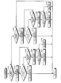
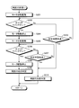
- G07F11/02—Coin-freed apparatus for dispensing, or the like, discrete articles from non-movable magazines
- G07F11/04—Coin-freed apparatus for dispensing, or the like, discrete articles from non-movable magazines in which magazines the articles are stored one vertically above the other
- G07F11/16—Delivery means
- G07F11/24—Rotary or oscillatory members
Definitions
- the present invention relates to a commodity carrying-out apparatus, and more specifically, it is applied to an automatic vending machine that sells commodities such as canned beverages and plastic bottled beverages, for example. It relates to an apparatus.
- a commodity storage rack is provided in a commodity storage inside a main body cabinet which is a vending machine main body.
- the product storage rack has a product storage passage extending along the vertical direction, and a product unloading device disposed in the lower part of the product storage passage.
- the commodity carry-out device is configured to include a lower pedal and an upper pedal.
- the lower pedal and the upper pedal are linked to an AC solenoid, which is an actuator, via a link, and appropriately moved to and from the product storage passage when the AC solenoid is energized.
- the upper pedal in the standby state, the upper pedal is in a state of being retreated from the product storage passage, while the lower pedal is in a state of advancing and moving to the product storage passage.
- the lower pedal contacts the lowermost product stored in the product storage passage, and the downward movement of the product stored in the product storage passage is restricted.
- the upper pedal is advanced to the product storage passage via the link when the AC solenoid is energized.
- the AC solenoid By moving and contacting the second lowest item, the item and items stored above the item are restricted from moving downward.
- the lower pedal retracts from the product storage passage, the lowermost product is carried out only downward, and when the product slips through the lower pedal, the lower pedal is attached with a spring. Move forward to the product storage passage by force.
- the present invention has an object of providing a commodity carrying-out apparatus capable of suppressing the plurality of commodities being carried out when the supply of power is interrupted due to a power failure or the like at the time of commodity carrying-out. Do.
- the commodity carrying-out apparatus is swingably disposed on the base in a manner to move forward and backward with respect to a commodity storage passage for storing an input commodity in the vertical direction.
- a pedal link for connecting the lower pedal and the upper pedal, the upper pedal being pivotally disposed on the base in a manner to move forward and backward with respect to the product storage passage in a region above the lower pedal
- the lower pedal is moved forward to the product storage passage while the upper pedal is retreated from the product storage passage by moving the pedal link downward, thereby moving the product downward.
- a product unloading device for retracting the lower pedal from the product storage passage while bringing the second pedal into contact with the second product and discharging the lowermost product downward
- the apparatus being rotatably disposed on the base about its own axis
- an output gear which is connected to a drive source via a worm gear and rotated by the driving force of the drive source transmitted via the worm gear, and is rotatably disposed on the base about its own axial center
- a plane including a portion in sliding contact with the cam portion is a plane including its own axis and the axis of the output gear. It is characterized by being substantially orthogonal to.
- the present invention is characterized in that, in the commodity carrying-out apparatus, the drive source is a direct current motor.
- the link lever is released when the elastically deformable locking portion formed on the link lever abuts on a predetermined portion and the sliding contact with the cam portion is released. It is characterized in that
- the locking portion is provided at a base end portion separated from an axial center of the link lever, and a concave portion is formed at a predetermined portion where the locking portion abuts. It is characterized by
- the present invention is characterized in that, in the above-mentioned commodity carrying-out apparatus, the link lever is determined in posture when the sliding contact with the cam portion is released by the biasing means.
- the tip end portion is disposed on the base in a mode in which the tip portion moves forward and backward with respect to the product storage passage in the upper region than the upper pedal.
- the lever retracts from the product storage passage against the biasing force of the biasing means.
- the output gear is rotatably disposed on the base about its own axial center and linked to the drive source via the worm gear, and rotated by the drive force of the drive source transmitted via the worm gear.
- the link lever is disposed on the base so as to be rotatable around its own axis and in sliding contact with the cam portion provided on the output gear, the link lever is maintained in the upward pivoted state and the pedal is By holding the link in the upward direction, the upper pedal is advanced to the product storage passage, and the lower pedal is retracted from the product storage passage while being in contact with the second product from the bottom. Products are transported downwards, and when the sliding contact with the cam unit is released, the pedal link is allowed to move downward to store the upper pedal.
- the lower pedal is advanced into the product storage passage while moving backward from the passage so as to restrict the downward movement of the product.
- the worm gear is interposed between the output gear and the drive source.
- the output gear can be held in the opposite direction without rotating in the opposite direction, whereby the pedal link can be held in the state of being moved upward. Therefore, the upper pedal can be held in the advanced movement state, and the power supply is interrupted due to a power failure or the like as in the prior art using the AC solenoid, whereby the AC solenoid is de-energized and the pedal link Does not move downward.
- the supply of power is cut off due to a power failure or the like at the time of product removal, it is possible to suppress the removal of a plurality of products.
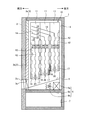
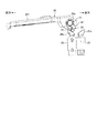
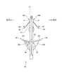
- FIG. 1 is a cross-sectional side view showing a case where an internal structure of a vending machine to which a commodity unloading apparatus according to an embodiment of the present invention is applied is viewed from the right side.
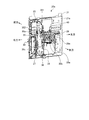
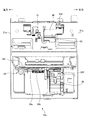
- FIG. 2 is a side view showing the commodity delivery apparatus shown in FIG. 1 as viewed from the right.
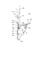
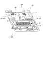
- FIG. 3 is a perspective view showing the commodity delivery apparatus shown in FIG. 1 as viewed from the right front side.
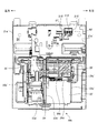
- FIG. 4 is a perspective view showing the commodity delivery apparatus shown in FIG. 1 as viewed from the rear right side.
- FIG. 5 is a perspective view showing the first commodity unloading device shown in FIGS. 2 to 4 as viewed from the rear right side.
- FIG. 6 is an explanatory view schematically showing a case where the main part of the first product unloading device shown in FIGS. 2 to 5 is viewed from the right side.
- FIG. 7 is an explanatory view schematically showing a case where the main part of the first commodity unloading device shown in FIGS. 2 to 5 is viewed from the right side.
- FIG. 8 is an explanatory view schematically showing a case where the main part of the first commodity unloading device shown in FIGS. 2 to 5 is viewed from the right side.
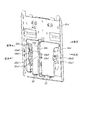
- FIG. 9 is a perspective view showing a base of the first commodity carry-out apparatus shown in FIGS.
- FIG. 10 is a perspective view showing a bearing and a harness guide attached to the base shown in FIG. FIG.
- FIG. 11 is a perspective view showing a first sold-out link and a second sold-out link.
- FIG. 12 is a side view showing the main part of the commodity delivery apparatus in FIG. 2 to FIG.
- FIG. 13 is a side view showing the relationship between the first sold-out link and the first sold-out detection switch when the lower pedal is in the product existing standby state.
- FIG. 14 is a perspective view of a rotation stopper which constitutes the first product carry-out apparatus shown in FIGS.
- FIG. 15 is a perspective view showing the relationship between the first sold-out link and the first sold-out detection switch when the lower pedal moves backward.
- FIG. 16 is a perspective view showing the main part of the drive unit in the first product unloading device, and showing the case viewed from the front right side.
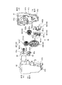
- FIG. 17 shows an essential part of the drive unit in the first product unloading device, and is an exploded perspective view showing the case viewed from the rear left side.
- FIG. 18 is a perspective view showing the second commodity unloading device shown in FIGS. 2 to 4 as viewed from the right front side.
- FIG. 19 is an explanatory view schematically showing a case where the main part of the second product unloading device shown in FIG. 2 to FIG. 4 and FIG. 18 is viewed from the right side.
- FIG. 20 is a perspective view showing a base of the second commodity carrying-out apparatus shown in FIG.
- FIG. 21 is a perspective view showing a bearing and a guide attached to the base shown in FIG.
- FIG. 22 is a block diagram showing a characteristic control system of the commodity delivery apparatus.
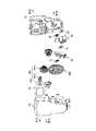
- FIG. 23 is a perspective view showing a case where the first product unloading device is viewed from the rear right side.
- FIG. 24 is a flowchart showing the contents of the payout control process performed by the payout control unit.
- FIG. 25 is a perspective view showing a case where the first product unloading device is viewed from the rear right side.
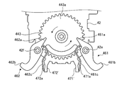
- FIG. 26 is an explanatory view showing the operation of the main part of the drive unit as viewed from the front.
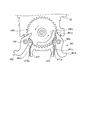
- FIG. 27 is an explanatory view showing the operation of the main part of the drive unit as viewed from the rear and the front.
- FIG. 28 is a flowchart showing the contents of the retrial process (1) in the payout control process shown in FIG. FIG.
- FIG. 29 is a flowchart showing the contents of the retrial process (2) in the payout control process shown in FIG.
- FIG. 30 is an exploded perspective view showing a modification of the drive unit.
- FIG. 31 is a perspective view showing a modified example of the commodity delivery apparatus.
- FIG. 32 is an explanatory view showing a main part of another modification of the drive unit as viewed from the front.
- FIG. 33 is an explanatory view showing an operation state of the main part shown in FIG.
- FIG. 34 is an explanatory view showing an operation state of the main part shown in FIG.
- FIG. 35 is a side view which shows typically the case where the other modification of a goods delivery apparatus is seen from the right side.
- FIG. 36 is a front view of the first product unloading device shown in FIG.
- FIG. 37 is a rear view of the first commodity carry-out apparatus shown in FIG.
- FIG. 38 is a perspective view of the second commodity carrying-out apparatus shown in FIG.
- FIG. 39 is a front view
- FIG. 1 is a cross-sectional side view showing a case where an internal structure of a vending machine to which a commodity unloading apparatus according to an embodiment of the present invention is applied is viewed from the right side.
- the vending machine illustrated here is for selling a product in a cooled or heated state, and is configured to include a main body cabinet 1, an outer door 2 and an inner door 3.
- the main body cabinet 1 is configured in a rectangular shape whose front surface is opened by combining a plurality of steel plates as appropriate, and has a commodity storage case 4 of a heat insulation structure inside thereof.
- the outer door 2 is for covering the front opening of the main body cabinet 1 and is disposed at one edge of the main body cabinet 1 so as to be openable and closable. Display window, commodity selection button, bill insertion slot, coin insertion slot, return lever, integrated indicator, coin return slot, commodity outlet 2a, etc. are required on the front of this outer door 2 when selling commodities etc. Things are provided.
- the inner door 3 is a heat insulating door divided into upper and lower halves for covering the front opening of the commodity storage case 4, and the upper heat insulating door 3 a is one side edge of the outer door 2 at a position inside the outer door 2.
- the lower heat insulating door 3 b is disposed at one side edge of the main body cabinet 1 so as to be openable and closable.
- a commodity outlet 3 c for carrying the commodity out of the commodity storage 4 is provided below the lower heat insulation door 3 b in the inner door 3.
- a commodity shooter 5 is provided inside the commodity storage 4, and a temperature control unit is provided in a region (hereinafter also referred to as "heat exchange region") below the commodity shooter 5.
- the product storage rack 10 is disposed in an area (hereinafter, also referred to as a "product storage area”) above the product shooter 5 while the 6 is disposed.
- the commodity shooter 5 is a plate-like member for guiding the commodity carried out of the commodity storage rack 10 to the commodity outlet 3c of the inner door 3, and is disposed in a manner to gradually incline downward toward the front side There is. Although not clearly shown in the figure, the commodity shooter 5 is provided with a large number of vent holes (not shown) for communicating between the heat exchange area and the commodity storage area.
- the temperature control unit 6 is for maintaining the internal atmosphere of the product storage case 4 at a desired temperature state, and includes an evaporator 6a of a refrigeration cycle, an electric heater 6b, and a blower fan 6c.
- this temperature control unit 6 for example, when the blower fan 6c is driven in a state where the refrigeration cycle is operated, the air cooled in the evaporator 6a is fed upward through the vent holes of the product shooter 5, so the product storage area Can be maintained at a low temperature.
- the blower fan 6c is driven in a state in which the electric heater 6b is energized, the air heated by the electric heater 6b is supplied upward through the vent holes of the product shooter 5, so the product storage area is maintained at high temperature. be able to.
- the compressor, the condenser and the expansion valve of the refrigeration cycle are disposed in the machine room 7 which is not shown in the figure but is outside the commodity storage case 4.
- the product storage racks 10 are arranged in three rows in the front and rear direction, and are configured in a serpentine shape along the vertical direction by arranging the passage components 12 between the pair of base side plates 11.
- a plurality of (two in the illustrated example) product storage channels 13 are provided, and a plurality of products are stored inside the product storage channels 13 in an upside-down posture along the vertical direction.
- the passage components 12 are appropriately disposed to face each other on the front side and the rear side of the commodity storage passage 13 and are fixed to the base side plate 11.
- two commodity storage passages 13 are provided adjacent to each other in the front and back direction.
- the front product storage passage 13 is also referred to as a first product storage passage 13a
- the rear product storage passage 13 is also referred to as a second product storage passage 13b.
- the passage component 12 is provided with a flapper which is not explicitly shown in the figure.
- the flapper is pivotally disposed in the passage component 12 in such a manner as to move forward and backward with respect to the commodity storage passage 13.
- the flapper is urged by a coil spring (not shown) to move forward into the product storage passage 13 in a normal state. Then, by coming into contact with the product passing through the product storage passage 13, the self moves backward along the meandering product storage passage 13 against the biasing force of the coil spring to correct the posture of the product. .
- the top tray 14 is provided in the upper part of the product storage passage 13 and the product delivery device 20 is provided in the lower part of the product storage passage 13.
- the top tray 14 is configured by bending a flat sheet metal, and is disposed between the base side plates 11 in a manner of being inclined gradually downward from the front to the rear.
- the upper surface of the top tray 14 as described above constitutes a commodity guiding passage 15 for guiding the commodity introduced through the inlet to the commodity storage passage 13.
- FIG. 2 to 4 respectively show the commodity delivery apparatus 20 shown in FIG. 1, and FIG. 2 is a side view showing the case viewed from the right side, and FIG. 3 is a perspective view showing the case viewed from the right front side FIG. 4 is a perspective view showing the case viewed from the rear right side.
- the commodity delivery apparatus 20 includes one commodity unloading device (hereinafter also referred to as a first commodity unloading device) 20a and the other commodity unloading device (hereinafter also referred to as a second commodity unloading device). And the second commodity delivery device 20b are held back to back and held together.
- FIGS. 2 to 4 show a state in which no commodity is stored in any of the first commodity unloading device 20a and the second commodity unloading device 20b which constitute the commodity delivery device 20.
- FIG. 5 is a perspective view showing the first product delivery device 20a shown in FIGS. 2 to 4 as viewed from the rear right side.
- the configuration of the first product unloading device 20a will be described, and then the second product unloading device 20b will be described.
- FIGS. 6 to 8 are explanatory views schematically showing the main part of the first commodity carry-out device 20a shown in FIGS. 2 to 5 as viewed from the right.
- the configuration of the first commodity carry-out device 20a will be described using FIG. 6 to FIG. 8 as appropriate.
- the first commodity carry-out device 20a is applied to the first commodity storage passage 13a, and is disposed below the first commodity storage passage 13a.
- the first product carry-out device 20a controls the behavior of the product between the opposing passage width defining plate 16 to store the product in the first product storage passage 13a in the standby state while driving.
- the function functions to carry out the corresponding products one by one to the product shooter 5, and includes a base 21.
- the base 21 is formed by cutting and bending a steel plate, and is disposed in such a manner that the surface of the base 21 faces the passage width determining plate 16.
- the side wall 21a is formed by bending both side portions of the base 21, and a first insertion hole 22 and a second insertion hole 23 are formed in the middle portion. The peripheral edges of the first insertion hole 22 and the second insertion hole 23 are bent in the same manner as the side wall 21 a to form a flange.
- the first insertion holes 22 and the second insertion holes 23 are formed side by side, and have the same size in the upper and lower dimensions.
- the first insertion hole 22 is located on the left side of the second insertion hole 23, and the left and right width of the first insertion hole 22 is the left and right of the second insertion hole 23. It is larger than the width.
- the first insertion holes 22 and the second insertion holes 23 are through openings (recesses for causing the lower pedal 28 and the upper pedal 29 described later to retract into the base 21 described later), which form a substantially rectangular shape as a whole.
- An upper end portion of the first insertion hole 22 protrudes leftward, and an upper end portion of the second insertion hole 23 protrudes rightward.
- a first left bearing piece 22 a is provided at the left side edge of the first insertion hole 22, and a first right bearing piece 22 b is provided at the right edge of the first insertion hole 22.
- a second left bearing piece 23a is provided at the left side edge of the second through hole 23, and a second right bearing piece 23b is provided at the right side edge of the second insertion hole 23.
- the first left bearing piece 22a and the second right bearing piece 23b correspond to flanges formed on the periphery of the first insertion hole 22 and the second insertion hole 23, respectively.
- the first right bearing piece 22b and the second left bearing piece 23a are integrally formed on the base 21 where the bearing portion 24 described later is fitted and held, and are formed in a U-shaped (discontinuous) cross section.
- the bearing holding portion has a function of maintaining the strength of the base 21 even when a large through opening formed of the first insertion hole 22 and the second insertion hole 23 having a substantially rectangular shape as a whole is formed in the base 21.
- a bearing 24 and a harness guide 25 as shown in FIG. 10 are attached to the base 21 having such a configuration.
- the bearing portion 24 is made of a resin material or the like, and is fitted between the first right bearing piece 22b and the second left bearing piece 23a.
- the harness guide 25 is made of a resin material or the like in the same manner as the bearing portion 24, and is fitted along the right side wall 21a of the base 21 in a manner adjacent to the second right bearing piece 23b.
- the harness guide 25 is for winding the harness of the electric component mounted on the first product unloading device 20a. Further, the harness guide 25 has a role as a guide member when the first product delivery device 20a and the second product delivery device 20b are held together back to back.
- the harness guide 25 is provided with a first sold-out detection switch 26 and a second sold-out detection switch 27.
- the first sold-out detection switch 26 is disposed in line with the second sold-out detection switch 27 in front of and behind the second sold-out detection switch 27.
- the first sold-out detection switch 26 is a so-called push-type switch, and includes a contact 26a biased to stand by a spring (not shown). When the contact 26a is not pressed, the first sold-out detection switch 26 is turned off and sends an off signal to the payout control unit 110 described later, while the contact 26a is pressed and the biasing force of the spring is applied. In the case of displacement in opposition, it is turned on to send an on signal to the payout control unit 110.
- the first sold-out detection switch 26 is turned off when the contact 26a is not pressed, but is turned on when the contact 26a is pressed and displaced. In the present invention, the first sold-out detection switch 26 may be turned on when the contact 26a is not pressed, but may be turned off when the contact 26a is pressed and displaced. .
- the second sold-out detection switch 27 is located rearward of the first sold-out detection switch 26.
- the second sold-out detection switch 27 is a so-called push-type switch, and includes a contact 27a biased to stand up by a spring (not shown).
- the second sellout detection switch 27 is turned off and sends an off signal to the payout control unit 110 described later, while the contact 27a is pressed and the biasing force of the spring is applied. In the case of displacement in opposition, it is turned on to send an on signal to the payout control unit 110.
- the second sold-out detection switch 27 is turned off when the contact 27a is not pressed, but is turned on when the contact 27a is pressed and displaced. In the present invention, the second sold-out detection switch 27 may be turned on when the contact 27a is not pressed, but may be turned off when the contact 27a is pressed and displaced. .
- the base 21 is provided with a first swing support shaft 28a and a second swing support shaft 29a.
- the first swing support shaft 28a extends in a substantially horizontal direction, and the first left bearing piece 22a, the first right bearing piece 22b, the second left bearing piece 23a, the second right bearing piece 23b, and the bearing portion It is a shaft-like member which is constructed to penetrate through the through holes 22a1, 22b1, 23a1, 23b1 and 24a formed in the lower part 24, and the lower pedal 28 is supported at the middle part thereof.
- a first sold-out link 30 is disposed at the right end of the first swing support shaft 28a.
- the first sold-out link 30 is configured to include a first sold-out base 31, a first sold-out abutting portion 32, and a first sold-out pressing portion 33.
- the first sold-out base portion 31 has a substantially disk shape, and is formed with a through hole 31a which allows the right end portion of the first swing support shaft 28a to pass therethrough.
- the first sold-out contact portion 32 extends leftward from the rear side portion of the first sold-out base 31.
- the first sold-out pressing portion 33 is formed to project rightward from the lower side portion of the first sold-out base 31.
- the through hole 31a formed in the first sold-out base portion 31 is formed larger than the first swing support shaft 28a, and the first sold-out link 30 can freely move relative to the first swing support shaft 28a. Is configured as.
- the second swing support shaft 29a extends in a substantially horizontal direction in a region above the first swing support shaft 28a, such that the first left bearing piece 22a, the first right bearing piece 22b, and the second left side It is a shaft-like member constructed to penetrate through the through holes 22a2, 22b2, 23b2, 23b2, and 24b formed in the bearing piece 23a, the second right bearing piece 23b, and the bearing portion 24, and the upper pedal 29 is provided at the middle portion thereof. Supports.
- the lower pedal 28 is a plate-like member, and is disposed in such a manner as to be able to swing around the central axis of the first swing support shaft 28 a by inserting the first swing support shaft 28 a at the base end portion. ing.
- the tip end portion of the lower pedal 28 extends outward in the radial direction of the first swing support shaft 28 a, and the first insertion hole 22 when swinging around the central axis of the first swing support shaft 28 a. It is possible to move forward and backward to the first product storage passage 13 a through the second insertion hole 23. That is, the lower pedal 28 is disposed swingably in such a manner as to move forward and backward with respect to the first product storage passage 13a.
- a lower pedal spring 28 b is interposed between the lower pedal 28 and the base 21.
- the lower pedal spring 28b always urges the lower pedal 28 in the advancing movement direction with respect to the first product storage passage 13a. More specifically, as shown in FIG. 6, the lower pedal spring 28b is in a standby position for waiting the lower pedal 28 such that the tip of the lower pedal 28 is positioned above the first swing support shaft 28a Also called attitude).
- the lower pedal spring 28b is at the same height level as the first swing support shaft 28a, as shown in FIG.
- the lower pedal 28 is placed in a standby position (hereinafter, also referred to as a product-present standby position) to be positioned.
- the base end of the lower pedal 28 abuts on the first sold-out contact portion 32 of the first sold-out link 30.
- the first sold-out link 30 rotates with the first swing support shaft 28 a as an axis, whereby the first sold-out pressing unit 33 presses the contact 26 a of the first sold-out detection switch 26.
- the contact 26a is pressed and displaced forward against the biasing force of the spring to be turned on and send an on signal to the payout control unit 110. It becomes.
- the lower pedal 28 when the lower pedal 28 is in the product-ready standby position, as shown in FIG. 13, the base end of the lower pedal 28 is separated from the first sold-out contact portion 32 of the first sold-out link 30.
- the first sold-out link 30 is in a free state.
- the contact 26a is turned up by being biased by the spring and thus becomes an off state, and an off signal is sent to the payout control unit 110. . That is, the first sold-out link 30 in the free state is rotated about the first swing support shaft 28 a as the first sold-out pressing portion 33 is pressed by the contact 26 a.
- the lower pedal 28 includes a plate-like pedal main body 281 and a pair of guide portions 282.
- the pair of guide portions 282 is provided on the back side of the pedal body 281.
- the respective guide portions 282 are plate-like members extending along the vertical direction, and are formed to face each other.
- Guide grooves 283 are formed on opposing surfaces of the guide portions 282 facing each other.
- the guide groove 283 is located at the lowermost position in the state (shown in FIG. 6) in which the lower pedal 28 is disposed at the advanced position where the lower pedal 28 has advanced most to the first product storage passage 13a.
- the state (shown in FIG. 8) in which the lower pedal 28 is disposed at the most retracted position with respect to the first product storage passage 13a (the state shown in FIG. 8)
- the first guide 283 b and the second guide 283 c are connected such that the contact portion 283 d located on the rotary stopper 36 and in contact with the pedal operation shaft 361 of the rotation stopper 36 and the insertion portion 283 a and the contact portion 283 d are continuous. And have.
- the first guiding portion 283b is disposed obliquely upward so as to be separated from the fitting portion 283a with respect to the base 21 in a state where the lower pedal 28 is disposed at the most advanced position (advanced position) with respect to the first product storage passage 13a.
- the guide portion 282 is formed in such a manner as to incline obliquely upward to approach the base 21 and reach the contact portion 283d.
- the second guiding portion 283c is inclined so as to be separated from the contact portion 283d with respect to the base 21 in a state where the lower pedal 28 is disposed at the most advanced position (advanced position) relative to the first product storage passage 13a. It is formed in the guide part 282 in the aspect which inclines below and reaches the insertion part 283a.
- the radially outward length of the lower pedal 28 from the first swing support shaft 28a is the passage width when it is positioned at the most advanced position (advanced position) with respect to the first product storage passage 13a. It is set to a length capable of securing a gap smaller than the maximum width of the narrowest product with the regulation plate 16.
- the upper pedal 29 is a plate-like member, and the base 21 can be rocked about the central axis of the second rocking support shaft 29a by inserting the second rocking support shaft 29a at the base end. It is arranged.
- the tip end portion of the upper pedal 29 extends outward in the radial direction of the second swing support shaft 29a, and the first insertion hole 22 when swinging around the central axis of the second swing support shaft 29a. It is possible to move forward and backward to the first product storage passage 13 a through the second insertion hole 23. That is, the upper pedal 29 is disposed swingably in such a manner as to move forward and backward with respect to the first product storage passage 13a.
- An upper pedal spring (not shown) is interposed between the upper pedal 29 and the base 21.
- the upper pedal spring always biases the upper pedal 29 in the backward movement direction with respect to the first product storage passage 13a.
- the upper pedal 29 is provided with a pressing inclined surface 291, a recess 292, a stopper contact portion 293 and a protrusion 294.
- the pressing inclined surface 291 is provided at the tip of the upper pedal 29, and when the upper pedal 29 is moved backward with respect to the first product storage passage 13a, the pressure inclined surface 291 is gradually lowered toward the first product storage passage 13a.
- a curved inclined surface formed in the following manner.
- the recess 292 is provided on the back side of the upper pedal 29 and is a single recess extending along a substantially horizontal direction formed in a manner of opening on both side surfaces of the upper pedal 29.
- the stopper abutting portion 293 is a portion on which a stopper pin 34 a described later abuts, and is provided in such a manner as to be inclined above the concave portion 292 on the back surface of the upper pedal 29.
- the projecting portion 294 is provided in a mode in which it protrudes toward the first product storage passage 13 a at the base end portion of the upper pedal 29.
- the upper pedal 29 is biased to move backward to the first product storage passage 13a by the biasing force of the upper pedal spring, but the stopper pin 34a abuts on the recess 292 to move to the first product storage passage 13a.
- the initial position is set to the state of backward movement.
- Such an upper pedal 29 passes the second rocking support shaft 29a in a state (state shown in FIG. 8) positioned at a position (advanced position) which has advanced most to the first product storage passage 13a. It is in an inclined state forward to the surface.
- the length of the radially outward direction from the second swing support shaft 29a of the upper pedal 29 is smaller than the maximum width of the product having a smaller maximum width with the passage width defining plate 16 in the above-described forward inclined state. It is set to the length which can secure a gap.
- a stopper pin 34a, a pedal stopper pin 34b and a stopper shaft 34c are provided between the bearing portion 24 and the second right bearing piece 23b.
- the stopper pin 34a is a shaft-like member disposed along the substantially horizontal direction between the bearing portion 24 and the second right bearing piece 23b, and one end thereof is the stopper pin insertion hole 23b3 of the second right bearing piece 23b. And the other end is inserted through the stopper pin insertion hole 24c1 of the bearing portion 24 exposed from the second left bearing piece 23a.
- the stopper pin 34a is coupled to the pedal link 35, and can move in the vertical direction inside the stopper pin insertion holes 23b3 and 24c1 as the pedal link 35 moves in the vertical direction.
- the stopper pin 34a is in contact with the recess 292 of the upper pedal 29 at the initial position.
- the pedal stopper pin 34b is a shaft-like member disposed along the substantially horizontal direction between the bearing portion 24 and the second right bearing piece 23b, and one end portion thereof is a pedal stopper pin support groove 24c2 of the bearing portion 24 (see FIG. Similar to the stopper pin insertion hole 24c1, it is a long groove extending up and down, is closed by a groove bottom which is a drawing-out portion of the reference numeral 24c1, and is inserted into the second right side.
- the pedal stopper pin support groove 23b4 of the bearing piece 23b is inserted.
- An insertion groove 23a4 is provided in the second right bearing piece 23a so that the pedal stopper pin insertion hole 24c2 is exposed.
- the pedal stopper pin 34b is coupled to the pedal link 35, and can be moved along the vertical direction inside the pedal stopper pin support grooves 23b4 and 24c2 as the pedal link 35 moves in the vertical direction. is there. When the pedal link 35 is moved in the vertical direction, the circumferential surface of the pedal stopper pin 34b slides in the grooves of the pedal stopper pin support grooves 23b4 and 24c2.
- the stopper shaft 34c is a shaft-like member disposed along the substantially horizontal direction between the bearing portion 24 and the second right bearing piece 23b, and one end thereof is inserted into the stopper shaft insertion hole 24c3 of the bearing portion 24. The other end portion is inserted through the through hole 23b5 of the second right bearing piece 23b. An insertion hole for the stopper shaft 34c is formed in the second right bearing piece 23a.
- the stopper shaft 34c supports a rotation stopper 36 at an intermediate portion thereof.
- the rotation stopper 36 allows the stopper shaft 34c to be inserted into the insertion hole of the base end portion and can swing around the central axis of the stopper shaft 34c.
- the tip end portion of the rotation stopper 36 extends outward in the radial direction of the stopper shaft 34c, and when pivoted around the central axis of the stopper shaft 34c, the first product storage passage 13a through the second insertion hole 23 It is possible to move forward and backward.
- the pivoting stopper 36 has the pedal operating shaft 361 as the pedal operating shaft 361 passes through the through hole 36 a at the tip end.
- the pedal operation shaft 361 is a shaft-like member disposed substantially in the horizontal direction, and both ends thereof are fitted in the guide groove 283 of the lower pedal 28.
- a pedal operating spring (not shown) is interposed between the rotation stopper 36 and the base 21.
- the pedal operation spring always biases the rotation stopper 36 in the advancing direction with respect to the first product storage passage 13a.
- Such a rotation stopper 36 is biased by the pedal operation spring in the direction of advancing and moving relative to the first product storage passage 13a, and the pedal stopper pin 34b enters the recess 36b of the rotation stopper 36.
- the movement in the backward movement direction is restricted by coming into contact with the pedal stopper pin 34b, and the initial position in the state of advancing and moving with respect to the first product storage passage 13a is set.
- both ends of the pedal operation shaft 361 of the rotation stopper 36 are positioned at the fitting portion 283a of the guide groove 283, and the lower pedal 28 is the first product.
- An initial position is set at a position moved forward to the storage passage 13a.
- such a rotation stopper 36 is provided with a flat blind portion 36c extending upward on the back side, that is, the back side of the recess 36b. .
- the blind portion 36c covers a portion of the pedal stopper pin 34b opposite to the first product storage passage 13a. More specifically, the blind portion 36c covers a portion of the pedal stopper pin 34b moving in the vertical direction, which is opposite to the first product storage passage 13a.
- the pedal link 35 is a long plate-like member extending along the vertical direction, and extends upward after the upper portion is bent forward. At the upper portion of the pedal link 35, a contact piece 351 extending rearward and then extending obliquely upward is provided, and a locking portion 352 for locking the link spring 35a is provided. .
- the link spring 35 a is interposed between the pedal link 35 and the base 21 and always biases the pedal link 35 downward.
- the stopper pin 34a is disposed at the lower end of the stopper pin insertion holes 23b3 and 24c1, and the lower end of the pedal stopper support groove 23b4 and 24c2
- the pedal stopper pin 34b is disposed on the In this state, the recess 292 of the upper pedal 29 disposed at the retracted position abuts against the stopper pin 34a.
- the rotation stopper 36 disposed at the advanced position is in contact with the pedal stopper pin 34b, and the backward movement of the rotation stopper 36 is restricted.
- the pedal operation shaft 361 of the rotation stopper 36 disposed at the advanced position is inserted into the insertion portion 283a of the lower pedal 28, whereby the backward movement of the lower pedal 28 disposed at the advanced position is restricted. There is.
- the stopper pin 34a is disposed at the upper end of the stopper pin insertion holes 23b3 and 24c1.
- the pedal stopper pin 34b is disposed at the upper end portion of the pedal stopper pin support grooves 23b4 and 24c2.
- the base end of the lower pedal 28 is separated from the first sold-out contact portion 32 of the first sold-out link 30, as shown in FIG.
- the sold-out link 30 is in a free state.
- the contact 26a is biased by the spring to be in an upright position, thereby maintaining the off state. That is, even when the lower pedal 28 moves backward, the first sold-out link 30 does not press the contact 26 a of the first sold-out detection switch 26 as in the product presence standby posture.
- the first commodity carry-out device 20a having such a configuration includes a drive unit 40 in addition to the above configuration.
- FIG. 16 and 17 show the main part of the drive unit 40 in the first product unloading device 20a, respectively, and FIG. 16 is an exploded perspective view showing the case seen from the front on the right side, and FIG. It is an exploded perspective view showing the case of
- the drive unit 40 is disposed in the central region of the upper portion on the back side of the base 21.
- the drive unit 40 includes a unit base 41 attached to the back of the base 21.
- the unit base 41 is formed of, for example, a resin material or the like, and is formed in a box shape whose rear surface is open.
- the unit cover 41 is closed by the attachment of a unit cover 42 made of resin to form an accommodation space between the unit base 41 and the unit cover 42.
- the motor 43, the gear member 44, the carrier switch 45, and the link lever 46 are housed in the housing space formed by the unit base 41 and the unit cover 42 in this manner.
- the motor 43 is a drive source, and is a direct-current motor capable of rotating in the forward and reverse directions in accordance with a command given from the payout control unit 110 described later.
- the motor 43 is disposed in a state of being held by the motor holding portion 41 a of the unit base 41.
- the gear member 44 is configured to include a worm gear 441, an intermediate gear 442 and an output gear 443.
- the worm gear 441 has a worm 441a and a worm wheel 441b.
- the worm 441 a has a cylindrical form and is attached to the output shaft 43 a of the motor 43.
- the worm wheel 441 b includes a disc-shaped first worm wheel 441 b 1 and a disc-shaped second worm wheel 441 b 2.
- the first worm wheel 441b1 is formed with a shaft-like portion that protrudes rearward at the central portion, and a gear portion formed of a plurality of teeth is formed on the circumferential surface.
- the second worm wheel 441b2 is located on the front side of the first worm wheel 441b1, and an axial portion whose central axis coincides with the central axis of the axial portion of the first worm wheel 441b1 protrudes forward.
- a gear portion formed of a plurality of teeth is also formed on the circumferential surface of the second worm wheel 441b2.
- Such a worm wheel 441b is inserted into the unit base 41 and the recesses 41b and 42b of the unit cover 42 while the gear portion of the first worm wheel 441b1 is engaged with the worm 441a. It is disposed rotatably around the central axis.
- the intermediate gear 442 includes a disk-shaped first intermediate gear 442 a and a disk-shaped second intermediate gear 442 b.
- the first intermediate gear 442a is formed with a shaft-like portion projecting rearward at the central portion and a gear portion formed of a plurality of teeth on the circumferential surface.
- the second intermediate gear 442b is located on the rear surface side of the first intermediate gear 442a, and an axial portion whose central axis coincides with the central axis of the axial portion of the first intermediate gear 442a protrudes forward. Are formed in the following manner. A gear portion formed of a plurality of teeth is also formed on the circumferential surface of the second intermediate gear 442b.
- the shaft-like portion is inserted through the unit base 41 and the concave portions 41c and 42c of the unit cover 42 in a state where the gear portion of the first intermediate gear 442a meshes with the gear portion of the second worm wheel 441b2.
- the output gear 443 has a disk shape having a diameter larger than that of the worm wheel 441 b and the intermediate gear 442.
- a gear portion composed of a plurality of teeth is also formed on the circumferential surface of the output gear 443. Further, at the central portion of the output gear 443 is formed an axial portion projecting in the front-rear direction. Further, the output gear 443 has a cam portion 443a formed on the front surface and a pressing piece 443b formed on the rear surface.
- the cam portion 443a has an arc shape and is formed in a manner of projecting forward.
- the cam portion 443a is formed so that its arc-like length is large enough to hold the state after the pedal link 35 is moved upward.
- the pressing piece 443b has a substantially V-like shape, and is formed in such a manner as to project rearward on the rear surface which is the surface opposite to the cam portion 443a.
- the output gear 443 has a shaft-like portion by inserting the shaft-like portion into the unit base 41 and the recesses 41 d and 42 d of the unit cover 42 while the gear portion is in mesh with the gear portion of the second intermediate gear 442 b. It is disposed rotatably around the central axis.
- the carrier switch 45 is a so-called push switch, and includes a contact 45a.
- the carrier switch 45 is disposed on the unit base 41 so as to be held slightly above the area where the output gear 443 is disposed.
- the carrier switch 45 is turned on when the contact 45a is pressed, and is supplied to the payout control unit 110 as an on signal to that effect, and is turned off when the contact 45a is not pressed. The fact is given to the payout control unit 110 as an off signal.
- the link lever 46 includes a first link lever 461 and a second link lever 462.
- the first link lever 461 is formed of, for example, a resin material, and a through hole 461a1 is formed in the base end 461a.
- the first link lever 461 has a hook shape that is curved obliquely upward to the right after the distal end portion 461b extends obliquely downward to the right from the proximal end portion 461a.
- a locking portion 461 c is provided at the proximal end 461 a of the first link lever 461.
- the locking portion 461c is an elastically deformable plate-like elastic member extending downward from the left end portion of the base end portion 461a.
- the first link lever 461 has a center of the first link shaft 42e on the front side of the output gear 443 by inserting the first link shaft 42e provided in the unit cover 42 into the through hole 461a1 of the base end 461a. It is arranged rotatably around an axis. In this case, the first link lever 461 passes through the right side opening (not shown) formed by the unit base 41 and the unit cover 42, and the tip 461b is located outside the unit base 41 and the unit cover 42. ing.
- the posture of the first link lever 461 in the normal state is determined by the engagement of the locking portion 461c with the left edge 471 of the right side opening.
- the second link lever 462 is formed of, for example, a resin material, and a through hole 462a1 is formed in the base end 462a.
- the second link lever 462 has a hook shape that is curved obliquely leftward and upward after the distal end portion 462b extends obliquely downward and leftward from the proximal end portion 462a.
- the front end portion 462 b of the second link lever 462 has a front-rear width greater than that of the front end portion 461 b of the first link lever 461.
- a locking portion 462 c is provided at the proximal end 462 a of the second link lever 462.
- the locking portion 462c is an elastically deformable plate-like elastic member extending downward from the right end portion of the proximal end portion 462a.
- the second link lever 462 has a center of the second link shaft 42f on the front side of the output gear 443 by inserting the second link shaft 42f provided in the unit cover 42 into the through hole 462a1 of the base end portion 462a. It is arranged rotatably around an axis. In this case, the second link lever 462 passes through a left opening (not shown) formed by the unit base 41 and the unit cover 42, and the tip portion 462b is located outside the unit base 41 and the unit cover 42. ing.
- the second link lever 462 has its posture in the normal state determined by the engagement of the locking portion 462c with the right edge 472 of the left opening.
- FIG. 18 is a perspective view showing the second commodity carry-out apparatus 20b shown in FIGS. 2 to 4 as viewed from the right front side.
- FIG. 19 is an explanatory view schematically showing a case where the main part of the second commodity carry-out device 20b shown in FIG. 2 to FIG. 4 and FIG. 18 is viewed from the right side.
- the second product delivery device 20b most of the components are common to the components of the first product delivery device 20a, and the front-back direction is different with respect to the components of the first product delivery device 20a.
- the left and right direction is the opposite.
- the illustration is appropriately omitted, and the components of the second product unloading device 20b that are common to the components of the first product unloading device 20a are the first product unloading.
- a brief explanation will be given by adding "'" to the code attached to the device 20a.
- the second commodity carry-out device 20b is applied to the second commodity storage passage 13b, and is disposed below the second commodity storage passage 13b.
- the second product carry-out device 20b controls the behavior of the product between the opposing passage width defining plate 17 to store the product in the second product storage passage 13b in the standby state while driving. , Functions to carry out the corresponding products one by one to the product shooter 5, and includes a base 21 '.
- the base 21 ' is formed by cutting and bending a steel plate, and is disposed in such a manner that its surface is opposed to the passage width defining plate 17.
- the side wall 21a ' is formed by bending both side portions of the base 21', and a first insertion hole 22 'and a second insertion hole 23' are formed in the middle portion.
- the peripheral edges of the first insertion holes 22 'and the second insertion holes 23' are bent in the same manner as the side walls 21a 'to form flanges.
- the first insertion holes 22 'and the second insertion holes 23' are formed side by side, and have the same size in the vertical dimension.
- the first insertion hole 22 ' is located on the right side of the second insertion hole 23', and the lateral width of the first insertion hole 22 'is the second.
- the width is larger than the lateral width of the insertion hole 23 '.
- the first insertion holes 22 'and the second insertion holes 23' are through openings (generally in the form of a rectangular shape as a whole as a whole) (recesses for retracting the lower pedal 28 'and the upper pedal 29' described later into the base 21 '.
- the first left bearing piece 22b 'and the second right bearing piece 23a' correspond to flanges formed on the periphery of the first insertion hole 22 'and the second insertion hole 23'.
- the first left bearing piece 22b 'and the second right bearing piece 23a' are formed integrally with the base 21 'for fitting and holding the bearing portion 24' described later, and have a U-shaped cross section It is formed in the shaft insertion flange which makes the square-C-shaped leg piece in the bearing holding
- a bearing 24 'and a guide 48 as shown in FIG. 21 are attached to the base 21' having such a configuration.
- the bearing portion 24 ' is made of a resin material or the like, and is fitted between the first left bearing piece 22b' and the second right bearing piece 23a '.
- the guide 48 is made of a resin material or the like in the same manner as the bearing portion 24 ', and is fitted to the base 21' in a manner adjacent to the second left bearing piece 23b '.
- the base 21 ' is provided with a first swing support shaft 28a' and a second swing support shaft 29a '.
- the first swing support shaft 28a ' extends in a substantially horizontal direction, and the first right bearing piece 22a', the first left bearing piece 22b ', the second right bearing piece 23a', and the second left bearing piece It is a shaft-like member constructed to penetrate through the through holes 22a1 ', 22b1', 23a1 ', 23b1', 24a 'formed in the bearing 23' and the bearing 24 ', and the lower pedal 28' It supports.
- a second sold-out link 50 is disposed at the right end of the first swing support shaft 28a '.
- the second sold-out link 50 is configured to include a second sold-out base 51, a second sold-out abutting portion 52, and a second sold-out pressing portion 53.
- the second sold-out base 51 is formed, for example, by connecting the lower ends of two disk-shaped portions 511 and 512 forming a C-shape with a connecting portion 513, and in each of the disk-shaped portions 511 and 512 Through holes 511a and 512a are formed to allow the right end portion of the first swing support shaft 28a 'to pass therethrough.
- the second sold-out contact portion 52 extends leftward from the front side portion of the disk-like portion 512 on the left side of the second sold-out base 51.
- the second sold-out contact portion 52 is provided on the left side of the first sold-out contact portion 32 of the first sold-out link 30 so as not to interfere with each other.
- the second sold-out pressing portion 53 is formed to project rightward from the lower side portion of the disk-shaped portion 511 on the right side of the second sold-out base 51.
- the through holes 511a, 512a formed in the second sold-out base portion 51 are formed larger than the first swing support shaft 28a ', and the second sold-out link 50 is free to the first swing support shaft 28a'. It is configured to be able to move.
- the second swing support shaft 29a ' extends in a substantially horizontal direction in a region above the first swing support shaft 28a'.
- the first right bearing piece 22a 'and the first left bearing piece 22b' A shaft installed through the through holes 22a2 ', 22b2', 23b2 ', 23b2', 24b 'formed in the second right bearing piece 23a', the second left bearing piece 23b 'and the bearing portion 24' And supports an upper pedal 29 'at its middle portion.
- the lower pedal 28 ' is a plate-like member and can be rocked about the central axis of the first rocking support shaft 28a' by inserting the first rocking support shaft 28a 'at the base end. It is arranged.
- the tip end portion of the lower pedal 28 ' extends outward in the radial direction of the first swing support shaft 28a', and the first portion of the lower pedal 28 'moves about the central axis of the first swing support shaft 28a'. It is possible to move back and forth to the second product storage passage 13b through the insertion hole 22 'and the second insertion hole 23'. That is, the lower pedal 28 'is disposed swingably in such a manner as to move forward and backward with respect to the second product storage passage 13b.
- a lower pedal spring 28b ' is interposed between the lower pedal 28' and the base 21 '.
- the lower pedal spring 28b 'always urges the lower pedal 28' toward the advancing movement with respect to the second product storage passage 13b. More specifically, as shown in FIG. 19, the lower pedal spring 28b 'has a standby posture (hereinafter referred to as "the lower pedal spring 28b" is positioned so that the tip of the lower pedal 28' is positioned above the first swing support shaft 28a '. , Also referred to as the product no standby state). When the product is placed on the upper surface of the lower pedal 28 ', the tip of the lower pedal 28' is positioned at the same height level as the first swing support shaft 28a '.
- the lower pedal 28 ' is made to be in a standby position (hereinafter also referred to as a product-present standby position).
- the contact 27a is turned up by being biased by the spring and thus becomes an off state, and an off signal is sent to the payout control unit 110. . That is, the second sold-out link 50 in the free state rotates about the first swing support shaft 28a 'as the second sold-out pressing portion 53 is pressed by the contact 27a. .
- the lower pedal 28 ' is provided with a plate-like pedal body 281' and a pair of guide portions 282 '.
- the pair of guide portions 282 ' are provided on the back side of the pedal body 281'.
- the respective guide portions 282 ' are plate-like members extending along the vertical direction, and are formed to face each other. Guide grooves (not shown) are formed on opposing surfaces of the respective guide portions 282 '.
- the guide groove is located at the lowermost position in a state in which the lower pedal 28 'is disposed at the advanced position where the lower pedal 28' is moved forward most with respect to the second product storage passage 13b, and a pedal operation shaft of a rotation stopper 36 '
- the rotary pedal 36 is positioned at the highest position and the rotation stopper 36.
- a first guide portion and a second guide portion connected such that the insertion portion and the contact portion are continuous.
- the first guiding portion is located obliquely upward so as to be separated from the fitting portion with respect to the base 21 'in a state where the lower pedal 28' is disposed at the most advanced position (advanced position) with respect to the second product storage passage 13b.
- the guide portion 282 ' is formed in such a manner as to incline obliquely upward to approach the base 21' and reach the contact portion.
- the second guiding portion is inclined so as to be separated from the contact portion with respect to the base 21 'in a state where the lower pedal 28' is disposed at the most advanced position (advanced position) with respect to the second product storage passage 13b. It is formed in the guide part 282 'in the aspect which inclines below and reaches an insertion part.
- a length smaller than the maximum width of a product having a small maximum width with the passage width defining plate 17 is set to a length that can be secured.
- the upper pedal 29 ' is a plate-like member, and can be rocked about the central axis of the second rocking support shaft 29a' by inserting the second rocking support shaft 29a 'at the base end. It is disposed on the base 21 '.
- the tip end portion of the upper pedal 29 ' extends outward in the radial direction of the second swing support shaft 29a', and the first pedal 29 'swings around the central axis of the second swing support shaft 29a'. It is possible to move back and forth to the second product storage passage 13b through the insertion hole 22 'and the second insertion hole 23'. That is, the upper pedal 29 'is disposed swingably in such a manner as to move forward and backward with respect to the second product storage passage 13b.
- An upper pedal spring (not shown) is interposed between the upper pedal 29 'and the base 21'.
- the upper pedal spring always biases the upper pedal 29 'in the backward movement direction with respect to the second product storage passage 13b.
- the upper pedal 29 ' is provided with a pressing inclined surface 291', a recess 292 ', a stopper abutment portion 293' and a projection 294 '.
- the pressing inclined surface 291 ' is provided at the tip of the upper pedal 29', and when the upper pedal 29 'is moved backward with respect to the second product storage passage 13b, it is directed to the second product storage passage 13b. It is a curved inclined surface formed in a manner of becoming gradually lower.
- the recess 292 ' is provided on the back side of the upper pedal 29', and is a single recess extending along a substantially horizontal direction formed in such a manner as to open on both sides of the upper pedal 29 '.
- the stopper abutting portion 293 ' is a portion on which a stopper pin described later abuts, and is provided in such a manner as to be inclined above the recess 292' on the back surface of the upper pedal 29 '.
- the projecting portion 294 ' is provided in a manner of projecting toward the second product storage passage 13b at the base end portion of the upper pedal 29'.
- the upper pedal 29 ' is biased to move backward to the second product storage passage 13b by the biasing force of the upper pedal spring, but the stopper pin abuts on the recess 292' to move the second product storage passage 13b.
- the initial position is set to the state of retreating with respect to.
- Such an upper pedal 29 ' is positioned forward of the vertical plane passing through the second swing support shaft 29a' in a state where the upper pedal 29 'is positioned at the most advanced position (advanced position) with respect to the second product storage passage 13b. It is in a tilted state.
- the length of the radial outward direction from the second swing support shaft 29a 'of the upper pedal 29' is greater than the maximum width of the product having a smaller maximum width with the passage width defining plate 17 in the above-described forward inclined state. Is set to a length that can ensure a small gap.
- a stopper pin (not shown), a pedal stopper pin 34b' and a stopper shaft 34c 'are provided between the bearing portion 24' and the second left bearing piece 23b '.
- the stopper pin is an axial member disposed along the substantially horizontal direction between the bearing portion 24 'and the second left bearing piece 23b'.
- the stopper pin is coupled to the pedal link 35 ', and can move along the vertical direction as the pedal link 35' moves in the vertical direction.
- the stopper pin is in contact with the recess 292 'of the upper pedal 29' at the initial position.
- the pedal stopper pin 34b ' is an axial member disposed along the substantially horizontal direction between the bearing portion 24' and the second left bearing piece 23b '.
- the pedal stopper pin 34b ' is coupled to the pedal link 35', and can move along the vertical direction as the pedal link 35 'moves in the vertical direction.
- the stopper shaft 34c ' is a shaft-like member disposed along the substantially horizontal direction between the bearing portion 24' and the second left bearing piece 23b ', and supports the rotation stopper 36' at the middle portion thereof. ing.
- the rotation stopper 36 ' inserts the stopper shaft 34c' into the insertion hole at the base end, and can swing around the central axis of the stopper shaft 34c ', and the bearing 24' and the second left bearing piece It is arranged between 23b '.
- the distal end portion of the rotation stopper 36 ' extends outward in the radial direction of the stopper shaft 34c', and when pivoted about the central axis of the stopper shaft 34c ', the second through hole 23' It is possible to move to and from the product storage passage 13b.
- the rotation stopper 36 ' has a pedal operation shaft 361' by passing a pedal operation shaft 361 '(see FIG. 4) through a through hole (not shown) at the tip end.
- the pedal operation shaft 361 ' is a shaft-like member disposed substantially in the horizontal direction, and both ends thereof are fitted into the guide grooves of the lower pedal 28'.
- a pedal operating spring (not shown) is interposed between the rotation stopper 36 'and the base 21'.
- the pedal operation spring always biases the rotation stopper 36 'toward the advancing movement with respect to the second product storage passage 13b.
- Such a rotation stopper 36 ' is biased by the pedal operation spring in the direction of advancing and moving to the second product storage passage 13b, and the pedal stopper pin 34b is engaged with the recess 36b' of the rotation stopper 36 '.
- the movement in the backward movement direction is restricted by the fact that the '' enters and abuts against the pedal stopper pin 34 b ', and the initial position in the state of advancing and moving to the second product storage passage 13 b is set There is.
- both ends of the pedal operation shaft 361 'of the rotation stopper 36' are positioned at the fitting portion of the guide groove, and the lower pedal 28 'is An initial position is set at a position moved forward to the second product storage passage 13b.
- a flat-plate-like blind portion 36c' extending upward on the back surface side, that is, the back surface side of the recess 36b 'is provided.
- the blind portion 36c ' covers a portion of the pedal stopper pin 34b' opposite to the second product storage passage 13b. More specifically, the blind portion 36c 'covers a portion of the pedal stopper pin 34b' moving in the vertical direction on the opposite side to the second product storage passage 13b.
- the pedal link 35 ' is a long plate-like member extending along the vertical direction, and extends upward after being bent rearward at the top. At the upper portion of the pedal link 35 ', a contact piece 351' extending forward and then obliquely upward is provided, and a locking portion 352 'for locking the link spring 35a' is provided. It is provided.
- the link spring 35a ' is interposed between the pedal link 35' and the base 21 'and always biases the pedal link 35' downward.
- the contact 27a is biased by the spring to be in an upright position, thereby maintaining the off state. That is, also when the lower pedal 28 'moves backward, the second sold-out link 50 does not press the contact 27a of the second sold-out detection switch 27, as in the product-presenting standby posture.
- the commodity delivery device 20 is configured by holding the first commodity unloading device 20a and the second commodity unloading device 20b having the above-described configuration back-to-back with the harness guide 25 as a guide member. And in this case, the first link lever 461 constituting the drive unit 40 has its tip end located in the lower area of the contact piece 351 of the pedal link 35, and the second link lever 462 has its tip end as a pedal It is located in the lower area of the contact piece 351 'of the link 35'.
- FIG. 22 is a block diagram showing a characteristic control system of the commodity delivery apparatus 20.
- the commodity delivery apparatus 20 includes a delivery control unit 110.
- the payout control unit 110 centrally controls the operation of the commodity delivery apparatus 20 in accordance with the program and data stored in the memory 111, and can communicate with the vending machine control unit 100 that controls the vending operation of the vending machine. It is.
- the cam portion 443a and the pressing piece 443b of the output gear 443 are located at the uppermost position, and the pressing piece 443b presses the contact 45a of the carrier switch 45. ing.
- the carrier switch 45 is turned on.
- the tip 461 b of the first link lever 461 constituting the drive unit 40 is at a position spaced downward from the contact piece 351 of the pedal link 35, and the tip 462 b of the second link lever 462 is It is at a position spaced downward from the contact piece 351 'of the pedal link 35'.
- the pedal link 35 is in the state of being disposed downward. Further, the product is placed on the upper surface of the lower pedal 28 by the product inserted into the first product storage passage 13a, so that the lower pedal 28 is in the product-ready standby state, and the upper pedal 29 is the first product storage. It has a posture of retreating movement from the passage 13a. As described above, since the lower pedal 28 is in the product-ready standby posture, the first sold-out detection switch 26 is in the posture in which the contact 26a is erected and is in the OFF state.
- the pedal link 35 ' is disposed at the lower side
- the lower pedal 28' is in the product standby state
- the upper pedal 29 ' is the second product storage passage. It has become a posture that has retreated from 13b.
- the second sold-out detection switch 27 is in the posture in which the contact 27a is erected and is in the off state.
- FIG. 24 is a flowchart showing the contents of the payout control process carried out by the payout control unit 110.
- the operation of the commodity delivery apparatus 20 will be described while describing the delivery control process.
- a product stored in the first product storage passage 13a will be referred to as a "first product”
- a product stored in the second product storage passage 13b will be described as a "second product”.
- step S101: Yes when the dispensing control unit 110 receives a discharge instruction of the first product from the vending machine control unit 100 (step S101: Yes), the motor 43 is driven to rotate forward (step S102).
- the surface (i) including the portion in sliding contact with the cam portion 443a is the center axis of itself (the center axis of the first link shaft 42e) Adjustment is made so as to be substantially orthogonal to a plane (b) including the stop axis of the output gear 443.
- the upper pedal 29 moved forward is brought into contact with the second lowest first product (hereinafter also referred to as the next product), and regulates that the next product moves downward.
- the pedal operating shaft 361 comes out of the insertion portion 283a, and the lower pedal 28 starts retreating movement against the biasing force of the lower pedal spring 28b by the weight of the product.
- the pedal operation shaft 361 of the rotation stopper 36 which has come out of the insertion portion 283a moves along the first guide portion 283b toward a position where the first guide portion 283b and the second guide portion 283c intersect.
- the lower pedal 28 retracts due to the weight of the lowest goods, and the downward movement of the lowest goods is permitted, and the lowest goods are unloaded downward (see FIG. 8).
- the carried-out goods are guided to the goods discharge port 3c through the goods shooter 5 and are in a state where they can be taken out via the goods outlet 2a.
- the lower pedal 28 is moved toward the advanced position by the elastic biasing force of the lower pedal spring 28b, and the rotation stopper 36 is also by the elastic biasing force of the pedal operation spring. Move toward the exit position.
- the pedal operation shaft 361 held at the position where the first guide portion 283 b and the second guide portion 283 c intersect is directed toward the insertion portion 283 a. Then, the lower pedal 28 and the rotation stopper 36 return to the advanced position.
- the upper pedal 29 is biased by the upper pedal spring, and retreats along with the downward movement of the stopper pin 34a.
- the downward movement of the next product is permitted, and then the downward movement of the next product is restricted by coming into contact with the lower pedal 28 which has moved forward, while the lower pedal 28 is shifted to the product presence standby state. Return to the standby state.
- the cam portion 443a comes in contact with the proximal end 462a of the second link lever 462 by the rotation of the output gear 443 in the clockwise direction as viewed from the front.
- the second link lever 462 is restricted in rotation around the central axis because the locking portion 462c is in contact with the right edge portion 472 of the left opening. Therefore, the locking portion 462c is elastically deformed so as to allow the proximal end portion 462a to approach the locking portion 462c, and the movement of the cam portion 443a due to the rotation of the output gear 443 is not inhibited.
- the payout control unit 110 monitors whether the carrier switch 45 is turned on in a predetermined time (step S103, step S104). That is, it is monitored whether or not the output gear 443 makes one rotation within a predetermined time.
- step S103 Yes, step S104: No
- step S105 the payout control unit 110 stops the normal rotation drive of the motor 43. Is returned to end this process. According to this, it is possible to well carry out the first product for which the carry-out command has been given as described above.
- step S200 If the carrier switch 45 is not turned on within the predetermined time, that is, if the on signal is not given from the carrier switch 45 within the predetermined time (step S103: No, step S104: Yes), the payout control unit 110 retries.
- the process (1) is performed (step S200).
- FIG. 28 is a flowchart showing the contents of the retrial process (1) in the payout control process shown in FIG.
- the payout control unit 110 reversely drives the motor 43 and monitors whether or not the carrier switch 45 is turned on within a predetermined time (step S201, step S202, step S203). ).
- the motor 43 is reversely driven in this manner, the output gear 443 to which the driving force of the motor 43 is transmitted via the worm gear 441 and the intermediate gear 442 rotates in a counterclockwise direction as viewed from the front.
- the motor 43 is reversely driven, at least the cam portion 443a of the output gear 443 is in contact with the proximal end 462a of the second link lever 462, that is, the cam 443a does not pass through the proximal end 462a. Therefore, even if the motor 43 is driven reversely, the second link lever 462 is not adversely affected (unloading the second commodity from the second commodity unloading device 20b).
- step S202 Yes, step S203: No
- step S204 the payout control unit 110 stops the reverse rotation drive of the motor 43 (step S204). Is driven to rotate forward again (step S205). Then, it is monitored whether or not the carrier switch 45 is turned on within a predetermined time (steps S206 and S207).
- step S206 Yes, step S207: No
- step S208 the carrier switch 45 is turned on within the predetermined time
- step S207 the output gear 443 rotates clockwise in the clockwise direction as viewed from the front within the predetermined time.
- step S206 No, step S207: Yes
- the payout control unit 110 determines that the retry has failed because it is a malfunction.
- step S210 After that, the procedure is returned, and the present retry process (1) is ended.
- the payout control unit 110 determines that the retry has failed. (Step S210) After that, the procedure is returned, and the present retry process (1) is ended.
- step S106 If the retry control is successful (step S106: Yes), the payout control unit 110 that has performed such retry processing (1) maintains the standby state (step S107), and then returns the procedure and this time. End the payout control process of According to this, it is possible to make the delivery of the first product possible by giving the delivery command of the new first product.
- step S106 if the retrial fails (step S106: No), it is judged that the first product in the first product storage passage 13a is sold out and the sellout determination is performed (step S108), and then the procedure is returned. End the process. According to this, it is possible to turn off the sale of the first commodity by turning on the sale sale lamp or the like as the first commodity is sold out.
- step S101 when the dispensing control unit 110 receives a discharge instruction of the second product from the vending machine control unit 100 (step S101: No, step S109: Yes), the motor 43 is reversely driven (step S110).
- the second link lever 462 when it is in sliding contact with the cam portion 443a, the surface including the portion in sliding contact with the cam portion 443a is its own central axis (the center of the second link shaft 42f It is adjusted to be substantially orthogonal to a plane including the axis) and the stop axis of the output gear 443.
- the upper pedal 29 ' which has advanced and moved in contact with the second product from the bottom (hereinafter, also referred to as a next product) regulates the movement of the next product downward.
- the lower pedal 28 ' is retracted due to the weight of the lowermost product, and the downward movement of the lowermost product is permitted, and the lowermost product is unloaded downward.
- the carried-out goods are guided to the goods discharge port 3c through the goods shooter 5 and are in a state where they can be taken out via the goods outlet 2a.
- the lower pedal 28' is moved toward the advanced position by the elastic biasing force of the lower pedal spring 28b ', and the rotation stopper 36' is also a pedal operating spring. It moves toward the advanced position by the elastic biasing force.
- the pedal operation shaft 361 'held at the position where the first guide portion and the second guide portion intersect is moved toward the insertion portion.
- the lower pedal 28 'and the rotation stopper 36' return to the advanced position.
- the upper pedal 29 ' is biased by the upper pedal spring and moves backward as the stopper pin moves downward.
- the downward movement of the next product is permitted, and then the downward movement of the next product is restricted while being in contact with the lower pedal 28 'which has moved forward, while the lower pedal 28' is shifted to the product presence standby state And return to the standby state.
- the cam portion 443a abuts on the proximal end 461a of the first link lever 461 by the rotation of the output gear 443 in the counterclockwise direction as viewed from the front.
- the rotation of the first link lever 461 about its central axis is restricted by the locking portion 461c being in contact with the left edge 471 of the right opening. Therefore, the locking portion 461c is elastically deformed so as to allow the proximal end portion 461a to approach the locking portion 461c, and the movement of the cam portion 443a due to the rotation of the output gear 443 is not inhibited.
- the payout control unit 110 monitors whether the carrier switch 45 is turned on in a predetermined time (step S111, step S112). That is, it is monitored whether or not the output gear 443 makes one rotation within a predetermined time.
- step S111 Yes, step S112: No
- step S113 the payout control unit 110 stops the reverse rotation drive of the motor 43 (step S113), and Return and complete this process. According to this, it is possible to well carry out the second product for which the carry-out command has been given as described above.
- step S111 When the carrier switch 45 is not turned on within the predetermined time, that is, when the on signal is not given from the carrier switch 45 within the predetermined time (step S111: No, step S112: Yes), the payout control unit 110 retries.
- the process (2) is performed (step S300).
- FIG. 29 is a flowchart showing the contents of the retrial process (2) in the payout control process shown in FIG.
- the payout control unit 110 drives the motor 43 to rotate forward and monitors whether the carrier switch 45 is turned on within a predetermined time (step S301, step S302, step S303). As described above, when the motor 43 is driven to rotate forward, the output gear 443 to which the driving force of the motor 43 is transmitted through the worm gear 441 and the intermediate gear 442 rotates clockwise as viewed from the front.
- step S302 Yes, step S303: No
- the payout control unit 110 stops the normal rotation drive of the motor 43 (step S304). 43 is reversely driven again (step S305). Then, it is monitored whether or not the carrier switch 45 is turned on within a predetermined time (steps S306 and S307).
- step S306 Yes, step S307: No
- step S306 Yes, step S307: No
- the output gear 443 makes one rotation counterclockwise as viewed from the front within the predetermined time.
- step S306 No, step S307: Yes
- the payout control unit 110 determines that the retry has failed because it is a malfunction.
- step S310 After that, the procedure is returned, and the present retry process (2) is ended. Further, even when the carrier switch 45 does not turn on within the predetermined time with respect to the procedure of step S301 (step S302: No, step S303: Yes), the payout control unit 110 determines that the retry has failed. (Step S310) After that, the procedure is returned, and the present retry process (2) is ended.
- step S114 If the retry control is successful (step S114: Yes), the payout control unit 110 that has performed such retry processing (2) maintains the standby state (step S115), and then returns the procedure and this time. End the payout control process of According to this, it is possible to make the delivery of the second product possible by giving the delivery command of the new second product.
- step S114 if the retrial fails (step S114: No), it is judged that the second product in the second product storage passage 13b is sold out and it is judged that the product is sold out (step S116). End the process. According to this, it is possible to stop the sale of the second product by turning on the sale-off lamp etc. as the second product is sold out.
- the lower pedal 28 of the first product carry-out device 20a is biased by the lower pedal spring 28b to be in the product non-standby posture.
- the first sold-out link 30 undergoes a first swing.
- the first sold-out pressing unit 33 presses the contact 26 a of the first sold-out detection switch 26 by rotating the support shaft 28 a as an axial center.
- the contact 26a is pressed and displaced forward against the biasing force of the spring to be turned on and send an on signal to the payout control unit 110. It becomes.
- the payout control unit 110 can turn on the sold-out lamp or the like as the first product is sold out.
- the contact 27a is pressed and displaced rearward against the biasing force of the spring to be in the ON state, and the ON signal is sent out to the payout control unit 110. It becomes. Accordingly, the payout control unit 110 can turn on the sold-out lamp or the like as the second product has been sold out.
- the payout control unit 110 may be configured to determine that the product is sold out when the on signal of the first sold-out detection switch 26 or the second sold-out detection switch 27 continues for a predetermined time or more. As a result, it is possible to prevent a malfunction due to chattering caused by bounce or the like when the lower pedal 28 (28 ') returns to the no-product standby position every time the product is sold, or when the lower pedal 28 returns.
- the commodity delivery apparatus and the commodity delivery apparatus 20 as described above have the following effects.
- the first sold-out detection switch 26 changes its state when the lower pedal 28 shifts to the commodity no-waiting attitude and the commodity-ready attitude, and the first commodity delivery passage 13a is
- the second sold-out detection switch 27 detects the presence or absence of a product, and the state changes when the lower pedal 28 'shifts to a no-product waiting attitude and a product-ready waiting attitude, and the second product storage passage 13b Since the presence or absence is detected, it can be reliably recognized that no product is present in the product storage passage 13, and the number of product sales opportunities can be made to coincide with the number of stored products in the product storage passage 13. Therefore, according to the 1st goods delivery apparatus 20a, the sales opportunity of goods can be increased.
- the eyelids 36c, 36c cover the side of the pedal stopper pins 34b, 34b 'opposite to the product storage passage 13 with the rotation stoppers 36, 36'. Because of the '', it is possible to maintain the anti-theft capability while reducing the number of parts without the need for a blind cover as in the prior art. Therefore, according to the 1st goods delivery apparatus 20a and the 2nd goods delivery apparatus 20b, while being able to aim at reduction of manufacturing cost, it can be made into a thing with good anti-theft property.
- the output gear 443 constituting the drive unit 40 is linked to the motor 43 via the worm gear 441 and rotated by the driving force of the motor 43 transmitted via the worm gear 441. It is a thing. Further, when the first link lever 461 and the second link lever 462 constituting the drive unit 40 are in sliding contact with the cam portion 443a provided in the output gear 443, the first link lever 461 and the second link lever 462 are maintained in the upward pivoted state.
- the worm gear 441 is interposed between the output gear 443 and the motor 43 even when the supply of power is interrupted due to a power failure or the like while the motor 43 is being driven. Even if the motor 43 is stopped, the output gear 443 can be held in the reverse direction without rotating in the reverse direction, whereby the pedal link 35, 35 'is held in the state of being moved upward. be able to. Therefore, the upper pedals 29, 29 'can be held in the advanced and moved state, and the power supply is interrupted due to a power failure or the like, as in the prior art using the AC solenoid. And the pedal link does not move downward.
- the first product delivery device 20a it is possible to suppress the delivery of a plurality of products when the supply of power is interrupted due to a power failure or the like at the time of product delivery.
- the surface (i) including the portion in sliding contact with the cam portion 443a is the axis of itself and the axis of the output gear 443 Since the output gear 443 is not subjected to a load in the rotational direction since it is substantially orthogonal to the plane (b) included, the pedal link 35, 35 'should be held in a state of being moved upward. Can.
- the first product delivery device 20a includes the motor 43 serving as a drive source of the first product delivery device 20a and the second product delivery device 20b, and the delivery command when the delivery command is given. Since the first product delivery device 20a and the second product delivery device 20b are alternatively selected according to the drive unit 40 for applying the driving force from the motor 43, the number of delivery mechanisms can be reduced. The number of driving sources can be reduced, and the manufacturing cost can be reduced. And since the 1st goods delivery apparatus 20a is equipped with the drive unit 40 containing the motor 43, only the 1st goods delivery apparatus 20a can also be used.
- the motor 43 which is a drive source is a direct current motor, it is not susceptible to regional voltage or frequency fluctuation, and installation at various locations becomes possible.
- the first sold-out detection switch 26 and the second sold-out detection switch 27 are installed in the first commodity delivery apparatus 20a, only the first commodity delivery apparatus 20a can be used. Also according to the number of the commodity storage passage 13 adjacent to back and forth, it is possible to correspond flexibly, and since the electric component part is disposed only in the first commodity delivery device 20a, the harness is provided in the first commodity delivery device 20a It can be consolidated.
- the first link lever 461 and the second link lever 462 contact the elastically deformable locking portions 461c and 462c formed on the first portion with the predetermined portions (471 and 472). Since the posture in the normal state is determined, it becomes easy to attach the unit cover 42 to the unit base 41.
- the payout control unit 110 performs the operation.
- the first commodity delivery apparatus 20a and the second commodity delivery apparatus 20a and 20b perform the selling-out process in which it is assumed that the commodity in the commodity storage passage 13 of the commodity delivery apparatus 20a and 20b is sold out. Even if one of the product carry-out devices 20b is sold out due to a sellout process, the other can continue carrying out the product, making it possible to perform detailed operations corresponding to each product storage passage 13. .
- the first sold-out detection switch 26 and the second sold-out detection switch 27 are disposed in the harness guide 25, the first commodity delivery apparatus 20a and the second commodity delivery apparatus 20b and The harness and the sold-out detection switches 26 and 27 can be well protected at the time of desorption.
- the first link lever 461 and the second link lever 462 have their attitudes determined in the normal state by the resiliently deformable locking portion 462c formed on the first link lever 461 and the second link lever 462 abutting on a predetermined portion.
- the spring 61 biases the link lever 46 'in a clockwise direction when viewed from the front, and the spring 61 biases the link lever 46' counterclockwise when viewed from the front.
- the springs 61, 62 may act as torsion springs, and the posture of the link lever 46 'in the normal state may be determined by the biasing force thereof.
- the first sold-out link 30 or the second sold-out link 50 is disposed on the first swing support shafts 28a, 28a 'of the lower pedals 28, 28' so that the lower pedals 28, 28 '
- the first sold-out detection switch 26 and the second sold-out detection switch 27 are in the on state by being in the product no standby state, in the present invention, as shown in FIG. 31, the lower pedals 28, 28 '.
- the lower lever member 71 may be provided in the upper area of the lower storage member 13 so as to move forward and backward with respect to the product storage passage 13.
- the lower lever member 71 is biased in such a manner as to advance and move into the product storage passage 13 by a lever spring (not shown) like the lower pedals 28 and 28 ', and when no product is placed on the upper surface, Of the lower levers 28, 28 'extend upward in a manner spaced apart from the upper surface of the lower pedals 28, 28', and a portion of the lower lever member 71 presses the contact 72 of the sold-out detection switch 27 not shown.
- the sold-out detection switch 27 is turned on.
- the upper surface of the lower lever member 71 is pressed by the product inserted into the product storage passage 13, the lower lever member 71 is in contact with the upper surfaces of the lower pedals 28, 28 '.
- the eyelids 36c and 36c ' are provided in the rotation stoppers 36 and 36' to maintain the anti-theft property.
- the upward movement of the pedal link is While restricting, when moving the pedal link upward by driving the drive unit, the anti-theft mechanism is provided by providing the anti-theft link mechanism that allows movement of the pedal link by disengaging from the upper area of the pedal link. It may be maintained.
- the first product delivery device 20a corresponds to the first product storage passage 13a
- the second product delivery device 20b corresponds to the second product storage passage 13b.
- the present invention is not limited to this, and one product delivery device may correspond to the other product storage passage, and the other product delivery device may correspond to one product storage passage.
- the locking portion 461 c of the first link lever 461 is provided at the proximal end portion 461 a of the first link lever 461, and the first link shaft 42 e that is the axial center of the first link lever 461. It is provided in the part away from.
- the connecting portion of the locking portion 461c with the base end portion 461a is offset obliquely upward to the left from the first link shaft 42e.
- the recessed part 471a is formed in left side edge part 471 'which the latching
- the recess 471a is configured to be gradually inclined to the left as it goes upward from the lower portion of the left edge 471 'and then to the right as it goes upward.
- the locking portion 462c of the second link lever 462 is provided at the proximal end 462a of the second link lever 462 and is separated from the second link shaft 42f, which is the axial center of the second link lever 462 It is provided.
- the connecting portion of the locking portion 462c with the base end portion 462a is deviated obliquely upward to the right from the second link shaft 42f.
- the recessed part 472a is formed in right side edge part 472 'which the latching
- the concave portion 472a is configured to be gradually inclined to the right as it goes upward from the lower portion of the right side edge 472 'and then to the left as it goes upward.
- the output gear 443 rotates counterclockwise as viewed from the front, as shown in FIG. 32, to rotate the second link lever 462 clockwise as viewed from the front.
- the cam portion 443a abuts on the proximal end 461a of the first link lever 461 as shown in FIG. 33 by the rotation of the output gear.
- the rotation of the first link lever 461 about its central axis is restricted by the locking portion 461c being in contact with the left side edge 471 'of the right side opening. Therefore, as shown in FIG. 34, the first link lever 461 elastically deforms to allow the proximal end 461a to approach the locking portion 461c, and the movement of the cam portion 443a due to the rotation of the output gear 443 is performed. It does not inhibit.
- the locking portion 461 is connected to the base end 461a at a position shifted obliquely upward to the left from the first link shaft 42e, so the left side It will be in contact with the edge 471 'while sliding upward. Since the recessed portion 471a is formed in the left side edge portion 471 ', the amount of deformation of the locking portion 461c at the time of elastic deformation of the first link lever 461 can be suppressed.
- FIG. 35 is a side view which shows typically the case where the other modification of a goods delivery apparatus is seen from the right side.
- the first product carry-out device 20a may include a lever member 80
- the second product carry-out device 20b may include a lever member 80 '.
- the lever member 80 is disposed swingably in such a manner as to be movable forward and backward with respect to the first product storage passage 13 a in a state of penetrating the lever opening 214 at the upper right end of the base 21.
- a pair of left and right lever locking pieces 215 that project rearward are formed at both side edges of the lever opening 214 on the back side of the base 21, and the lever member 80 is shown in FIG.
- FIG. 37 it is arranged so as to be pivotable about the axial center of a shaft 81 which is bridged by the lever locking piece 215.
- a lever spring 82 is interposed between the lever member 80 and the base 21 in such a manner as to wind the shaft 81.
- the lever member 80 is urged by the lever spring 82, and the tip end portion 85 is normally held. Is advanced to the first product storage passage 13a.
- the lever member 80 ' can be advanced and retracted relative to the second product storage passage 13b in a state of penetrating the lever opening 214' at the upper right end of the base 21 '. It is arranged swingably. More specifically, on the back side of the base 21 ', a pair of left and right lever locking pieces 215' protruding rearward are formed on both side edges of the lever opening 214 ', and the lever member 80' The lever locking piece 215 'is pivotably arranged around the axial center of a shaft 81'.
- a lever spring 82 ' is interposed between the lever member 80' and the base 21 'in a manner to wind the shaft 81'.
- the lever member 80 ' is biased by the lever spring 82', In the normal state, the leading end portion 85 'is in a position where it has advanced and moved into the second product storage passage 13b.
- the bases 21 and 21 ' move in such a manner that the leading end portion moves forward and backward with respect to the commodity storage passage 13 in the region above the upper pedals 29 and 29'.
- the lever members 80 and 80 'disposed on the side are urged by the lever springs 82 and 82', and the leading end portions 85 and 85 'move forward to the commodity storage passage 13, while passing the commodity storage passage
- it abuts against the biasing force of the lever spring 82, 82 ' it retreats from the product storage passage 13, so that it is possible to stabilize the posture of the product which has passed through the product storage passage 13.
Landscapes
- Physics & Mathematics (AREA)
- General Physics & Mathematics (AREA)
- Vending Machines For Individual Products (AREA)
Abstract
商品収納通路(13)に対し進退移動する下ペダル(29)及び上ペダル(28)と、これらを連係するペダルリンク(35)とを備え、待機状態においては、ペダルリンク(35)を下方向に移動させて商品が下方へ移動することを規制し、駆動する場合には、ペダルリンク(35)を上方向に移動させて最下位の商品を下方に搬出する商品搬出装置(20a)において、ウォームギア(441)を介してモータ(43)に連係され、かつ該ギア(441)を介して伝達されるモータ(43)の駆動力により回転する出力ギア(443)と、出力ギア(443)に設けられたカム部(443a)と摺接する場合には、ペダルリンク(35)を上方向移動させた状態に保持し、カム部(443a)との摺接が解除される場合には、ペダルリンク(35)が下方向移動することを許容するリンクレバー(46)を備えている。
Description
本発明は、商品搬出装置に関し、より詳細には、例えば缶入り飲料やペットボトル入り飲料等の商品を販売する自動販売機に適用され、商品収納通路に収納された商品を適宜搬出する商品搬出装置に関するものである。
従来、例えば缶入り飲料やペットボトル入り飲料等の商品を販売する自動販売機では、自動販売機本体である本体キャビネットの内部の商品収容庫に商品収納ラックが設けられている。商品収納ラックは、上下方向に沿って延在する商品収納通路と、商品収納通路の下部に配設された商品搬出装置とを有している。
商品搬出装置は、下ペダルと上ペダルとを備えて構成されている。下ペダル及び上ペダルは、リンクを介してアクチュエータであるACソレノイドに連係されており、ACソレノイドが通電状態となることによりそれぞれ商品収納通路に適宜進退移動するものである。
このような商品搬出装置では、待機状態において、上ペダルが商品収納通路から退行移動した状態にある一方、下ペダルが商品収納通路に進出移動した状態にある。これにより、下ペダルが商品収納通路に収納される最下位の商品に当接し、商品収納通路に収納された商品の下方への移動が規制されている。
そして、商品の搬出指令が与えられた場合、該当する商品を収納する商品収納通路の下部の商品搬出装置では、ACソレノイドが通電状態となることによりリンクを介して上ペダルが商品収納通路に進出移動し、最下位から2番目の商品に当接することによって、該商品、並びに該商品よりも上方に収納された商品が下方に向けて移動することを規制する。また、上記ACソレノイドが通電状態となることにより下ペダルが商品収納通路から退行移動し、最下位の商品が唯一下方に向けて搬出され、商品が下ペダルを擦り抜けると下ペダルがばねの付勢力により商品収納通路に進出移動する。その後、ACソレノイドの通電状態が解除されて非通電状態となると、商品収納通路に進出移動した下ペダルが退行移動を規制された状態となって上ペダルが商品収納通路から退行移動した状態となることで、上述した待機状態に復帰する(例えば、特許文献1参照)。
ところが、上述した特許文献1に提案されている商品搬出装置では、アクチュエータとしてACソレノイドが用いられていたために次のような問題があった。すなわち、ACソレノイドが通電状態となることでリンクを上方に向けて移動させて上ペダルが商品収納通路に進出移動している途中で、すなわち上ペダルが進出移動している途中で停電等により電力の供給が遮断されると、ACソレノイドは非通電状態となる。これによりリンクは下方に向けて移動することとなり、上ペダルも退行移動することとなる。そして、リンクが下方に向けての移動が完了するまでの間、すなわち下ペダルが商品収納通路に進出移動して退行移動が規制された状態となるまでの間、複数の商品が搬出されてしまう虞れがあった。
本発明は、上記実情に鑑みて、商品搬出時に停電等により電力の供給が遮断された場合において複数の商品が搬出されてしまうことを抑制することができる商品搬出装置を提供することを目的とする。
上記目的を達成するために、本発明に係る商品搬出装置は、投入された商品を上下方向に沿って収納する商品収納通路に対し進退移動する態様でベースに揺動可能に配設された下ペダルと、前記下ペダルよりも上方域において前記商品収納通路に対し進退移動する態様で前記ベースに揺動可能に配設された上ペダルと、前記下ペダルと前記上ペダルとを連係するペダルリンクとを備え、待機状態においては、前記ペダルリンクを下方向に向けて移動させることで前記上ペダルを商品収納通路から退行移動させつつ前記下ペダルを商品収納通路に進出移動させて商品が下方へ向けて移動することを規制する一方、駆動する場合には、前記ペダルリンクを上方向に向けて移動させることで前記上ペダルを商品収納通路に進出移動させて最下位から2番目の商品に当接させつつ前記下ペダルを商品収納通路より退行移動させて最下位の商品を下方に向けて搬出する商品搬出装置において、前記ベースに自身の軸心回りに回転可能に配設されるとともにウォームギアを介して駆動源に連係され、かつ該ウォームギアを介して伝達される前記駆動源の駆動力により回転する出力ギアと、前記ベースに自身の軸心回りに回動可能に配設され、かつ前記出力ギアに設けられたカム部と摺接する場合には、上方に向けて回動した状態に維持されて前記ペダルリンクを上方向に向けて移動させた状態に保持する一方、前記カム部との摺接が解除される場合には、前記ペダルリンクが下方向に向けて移動することを許容するリンクレバーとを備えたことを特徴とする。
また本発明は、上記商品搬出装置において、前記リンクレバーは、前記カム部と摺接する場合、該カム部と摺接する部分を含む面が自身の軸心と前記出力ギアの軸心とを含む平面に対して略直交することを特徴とする。
また本発明は、上記商品搬出装置において、前記駆動源は、直流モータであることを特徴とする。
また本発明は、上記商品搬出装置において、前記リンクレバーは、自身に形成された弾性変形可能な係止部が所定部位に当接することで前記カム部との摺接が解除される場合の姿勢が決められていることを特徴とする。
また本発明は、上記商品搬出装置において、前記係止部は、前記リンクレバーの軸心から離隔した基端部に設けられており、前記係止部が当接する所定部位には凹部が形成されていることを特徴とする。
また本発明は、上記商品搬出装置において、前記リンクレバーは、付勢手段により前記カム部との摺接が解除される場合の姿勢が決められていることを特徴とする。
また本発明は、上記商品搬出装置において、前記上ペダルよりも上方域において前記商品収納通路に対し先端部が進退移動する態様で前記ベースに配設され、常態においては付勢手段に付勢されて先端部が前記商品収納通路に進出移動する一方、前記商品収納通路を通過する商品に当接される場合には前記付勢手段の付勢力に抗して前記商品収納通路より退行移動するレバー部材を備えたことを特徴とする。
本発明によれば、出力ギアがベースに自身の軸心回りに回転可能に配設されるとともにウォームギアを介して駆動源に連係され、かつウォームギアを介して伝達される駆動源の駆動力により回転するものである。また、リンクレバーがベースに自身の軸心回りに回動可能に配設され、かつ出力ギアに設けられたカム部と摺接する場合には、上方に向けて回動した状態に維持されてペダルリンクを上方向に向けて移動させた状態に保持することで、上ペダルを商品収納通路に進出移動させて最下位から2番目の商品に当接させつつ下ペダルを商品収納通路より退行移動させて最下位の商品を下方に向けて搬出するようにし、カム部との摺接が解除される場合には、ペダルリンクが下方向に向けて移動することを許容することで上ペダルを商品収納通路から退行移動させつつ下ペダルを商品収納通路に進出移動させて商品が下方へ向けて移動することを規制するようにしている。このような商品搬出装置においては、駆動中において停電等により電力の供給が遮断された場合においても、出力ギアと駆動源との間にウォームギアが介在しているため、駆動源が駆動停止しても出力ギアが逆方向に回転しまうことがなくその状態を保持することができ、これによりペダルリンクを上方に移動させた状態で保持することができる。そのため、上ペダルを進出移動した状態に保持することができ、ACソレノイドを用いた従来技術のように、停電等によって電力の供給が遮断されることでACソレノイドが非通電状態となってペダルリンクが下方に向けて移動してしまうことがない。これにより、商品搬出時に停電等により電力の供給が遮断された場合において複数の商品が搬出されてしまうことを抑制することができるという効果を奏する。
以下に添付図面を参照して、本発明に係る商品搬出装置の好適な実施の形態について詳細に説明する。
図1は、本発明の実施の形態である商品搬出装置が適用された自動販売機の内部構造を右側から見た場合を示す断面側面図である。ここで例示する自動販売機は、商品を冷却若しくは加熱した状態で販売するもので、本体キャビネット1、外扉2及び内扉3を備えて構成されている。
本体キャビネット1は、複数の鋼板を適宜組み合わせることによって前面が開口した直方状に構成されたもので、その内部に断熱構造の商品収容庫4を有している。外扉2は、本体キャビネット1の前面開口を覆うためのもので、本体キャビネット1の一側縁部に開閉可能に配設されている。この外扉2の前面には、ディスプレイウィンドウ、商品選択ボタン、紙幣挿通口、硬貨投入口、返却レバー、一体表示器、硬貨返却口、商品取出口2a等々、商品を販売する際に必要となるものが設けられている。内扉3は、商品収容庫4の前面開口を覆うための上下二分割された断熱扉であり、外扉2よりも内方となる位置において上部断熱扉3aは外扉2の一側縁部に開閉可能に配設され、下部断熱扉3bは本体キャビネット1の一側縁部に開閉可能に配設されている。この内扉3における下部断熱扉3bの下方部には、商品を商品収容庫4の外部に搬出するための商品搬出口3cが設けられている。
また、上記自動販売機には、商品収容庫4の内部に商品シュータ5が設けられており、この商品シュータ5よりも下方となる領域(以下、「熱交換領域」ともいう)に温度調節ユニット6が配設されている一方、商品シュータ5よりも上方となる領域(以下、「商品収納領域」ともいう)に商品収納ラック10が配設されている。
商品シュータ5は、商品収納ラック10から搬出された商品を内扉3の商品搬出口3cに案内するためのプレート状部材であり、前方側に向けて漸次下方に傾斜する態様で配設されている。図には明示していないが、この商品シュータ5には、熱交換領域と商品収納領域との間を連通させる通気孔(図示せず)が多数穿設されている。
温度調節ユニット6は、商品収容庫4の内部雰囲気を所望の温度状態に維持するためのもので、冷凍サイクルの蒸発器6a、電熱ヒータ6b及び送風ファン6cを備えて構成されている。この温度調節ユニット6においては、例えば冷凍サイクルを運転した状態で送風ファン6cを駆動すると、蒸発器6aにおいて冷却された空気が商品シュータ5の通気孔を通じて上方に送給されるため、商品収納領域を低温状態に維持することができる。一方、電熱ヒータ6bに通電した状態で送風ファン6cを駆動すると、電熱ヒータ6bによって加熱された空気が商品シュータ5の通気孔を通じて上方に送給されるため、商品収納領域を高温状態に維持することができる。尚、冷凍サイクルの圧縮機、凝縮器及び膨張弁は、図には明示しないがいずれも商品収容庫4の外部となる機械室7に配設されている。
上記商品収納ラック10は、前後3列に並ぶように配設されており、一対のベース側板11の間に通路構成要素12が配設されることによって上下方向に沿って蛇行状に構成された複数(図示の例では2つ)の商品収納通路13を備え、これら商品収納通路13の内部に上下方向に沿って複数の商品を横倒し姿勢で収納するものである。より詳細に説明すると、通路構成要素12は、商品収納通路13の前方側と、後方側とに互いに対向するよう適宜配設されたものであって、ベース側板11に固定されている。これにより各商品収納ラック10においては、2つの商品収納通路13が互いに前後に隣接する態様で設けられている。以下においては、一つの商品収納ラック10において、前方側の商品収納通路13を第1商品収納通路13aとも称し、後方側の商品収納通路13を第2商品収納通路13bとも称することとする。
また、通路構成要素12には、図には明示しないフラッパが設けられている。フラッパは、商品収納通路13に対して進退移動する態様で通路構成要素12に揺動可能に配設されている。このフラッパは、コイルバネ(図示せず)に付勢されて常態においては商品収納通路13に進出移動した姿勢となる。そして、商品収納通路13を通過する商品に当接することにより自身はコイルバネの付勢力に抗して蛇行状の商品収納通路13に沿うように退行移動して該商品の姿勢を修正するものである。
上記商品収納ラック10においては、商品収納通路13の上部にトップトレイ14が設けられている一方、商品収納通路13の下部に商品払出装置20が設けられている。
トップトレイ14は、平板状の板金を屈曲して構成されるもので、前方から後方に向けて漸次下方に傾斜する態様でベース側板11間に配設されている。このようなトップトレイ14の上面は、投入口を通じて投入された商品を商品収納通路13まで案内する商品案内通路15を構成している。
図2~図4は、それぞれ図1に示した商品払出装置20を示すもので、図2は右方から見た場合を示す側面図、図3は右側前方から見た場合を示す斜視図、図4は右側後方から見た場合を示す斜視図である。
これら図2~図4に示すように、商品払出装置20は、一方の商品搬出装置(以下、第1商品搬出装置とも称する)20aと、他方の商品搬出装置(以下、第2商品搬出装置とも称する)20bとを備えており、これら第1商品搬出装置20aと第2商品搬出装置20bとが互いに背中合わせに抱き合わされて構成されている。尚、これら図2~図4においては、商品払出装置20を構成する第1商品搬出装置20a及び第2商品搬出装置20bのいずれも商品が収納されていない状態を示している。
図5は、図2~図4に示した第1商品搬出装置20aを右側後方から見た場合を示す斜視図である。以下においては、第1商品搬出装置20aの構成について説明し、その後に第2商品搬出装置20bについて説明する。
図6~図8は、それぞれ図2~図5に示した第1商品搬出装置20aの要部を右方より見た場合を模式的に示す説明図である。以下の説明においては、これら図6~図8も適宜利用しつつ第1商品搬出装置20aの構成について説明する。
第1商品搬出装置20aは、第1商品収納通路13aに適用されるもので、この第1商品収納通路13aの下部に配設されている。この第1商品搬出装置20aは、対向する通路幅規定板16との間において商品の挙動を制御することにより、待機状態においては第1商品収納通路13aに商品を収納する一方、駆動する場合には対応する商品を1つずつ商品シュータ5に搬出するように機能するもので、ベース21を備えている。
ベース21は、図9に示すように、鋼板に切削加工及び屈曲加工を施して構成されたものであり、自身の表面を通路幅規定板16に対向させる態様で配設されている。このベース21は、両側部が屈曲されることで側壁21aが形成されている一方、中間部に第1挿通孔22及び第2挿通孔23が形成されている。第1挿通孔22及び第2挿通孔23の周縁は側壁21aと同様に屈曲されてフランジが形成されている。
第1挿通孔22と第2挿通孔23とは、互いに左右に並ぶよう形成されており上下寸法が同じ大きさを有している。これら第1挿通孔22と第2挿通孔23とでは、第1挿通孔22が第2挿通孔23の左側に位置しており、第1挿通孔22の左右幅が第2挿通孔23の左右幅よりも大きいものである。また第1挿通孔22と第2挿通孔23とは、互いに全体として略矩形状の形態を成す貫通開口(後述する下ペダル28及び上ペダル29をベース21内に退行させる凹部)であり、第1挿通孔22の上端部が左方に突出しており、第2挿通孔23の上端部が右方に突出している。第1挿通孔22の左側縁部には第1左側軸受片22aが設けられ、かつ第1挿通孔22の右側縁部には第1右側軸受片22bが設けられており、第2挿通孔23の左側縁部には、第2左側軸受片23aが設けられ、かつ第2挿通孔23の右側縁部には、第2右側軸受片23bが設けられている。尚、第1左側軸受片22a及び第2右側軸受片23bは、第1挿通孔22及び第2挿通孔23の周縁に形成したフランジに相当するものである。また、第1右側軸受片22b及び第2左側軸受片23aは、後述する軸受部24を嵌合保持するところの、ベース21に一体に形成されるとともに横断面コ字状(不連続)に形成された軸受保持部におけるコ字状の両脚片をなす軸挿通フランジに形成されているものである。また、この軸受保持部は、全体として略矩形状の形態を成す第1挿通孔22と第2挿通孔23からなる大きな貫通開口をベース21に形成した場合にもベース21の強度を維持する機能を有する。
このような構成を有するベース21には、図10に示すような軸受部24及びハーネスガイド25が装着されている。軸受部24は、樹脂材料等により構成されるもので、第1右側軸受片22bと第2左側軸受片23aとの間に嵌装されている。
ハーネスガイド25は、軸受部24と同様に樹脂材料等により構成されるもので、第2右側軸受片23bに隣接する態様でベース21の右側の側壁21aに沿って嵌装されている。このハーネスガイド25は、第1商品搬出装置20aに装着される電装部品のハーネスを這わせるためのものである。また、ハーネスガイド25は、第1商品搬出装置20aと第2商品搬出装置20bとを互いに背中合わせに抱き合わせる際にガイド部材としての役割を有している。
かかるハーネスガイド25には、第1売切検知スイッチ26及び第2売切検知スイッチ27が配設されている。
第1売切検知スイッチ26は、第2売切検知スイッチ27と前後に並ぶように配設されており、該第2売切検知スイッチ27よりも前方側に位置している。この第1売切検知スイッチ26は、いわゆるプッシュ型スイッチであり、図示せぬバネにより起立するよう付勢された接触子26aを備えている。かかる第1売切検知スイッチ26は、接触子26aが押圧されない状態では、オフ状態となって後述する払出制御部110にオフ信号を送出する一方、接触子26aが押圧されてバネの付勢力に抗して変位する場合には、オン状態となって払出制御部110にオン信号を送出するものである。
尚、本実施の形態では、第1売切検知スイッチ26は、接触子26aが押圧されない状態でオフ状態となる一方、接触子26aが押圧されて変位する場合にオン状態となるものであるが、本発明においては、第1売切検知スイッチ26は、接触子26aが押圧されない状態でオン状態となる一方、接触子26aが押圧されて変位する場合にオフ状態となるものであってもよい。
第2売切検知スイッチ27は、第1売切検知スイッチ26よりも後方側に位置している。この第2売切検知スイッチ27は、いわゆるプッシュ型スイッチであり、図示せぬバネにより起立するよう付勢された接触子27aを備えている。かかる第2売切検知スイッチ27は、接触子27aが押圧されない状態では、オフ状態となって後述する払出制御部110にオフ信号を送出する一方、接触子27aが押圧されてバネの付勢力に抗して変位する場合には、オン状態となって払出制御部110にオン信号を送出するものである。
尚、本実施の形態では、第2売切検知スイッチ27は、接触子27aが押圧されない状態でオフ状態となる一方、接触子27aが押圧されて変位する場合にオン状態となるものであるが、本発明においては、第2売切検知スイッチ27は、接触子27aが押圧されない状態でオン状態となる一方、接触子27aが押圧されて変位する場合にオフ状態となるものであってもよい。
上記ベース21には、第1揺動支持軸28a及び第2揺動支持軸29aが設けられている。第1揺動支持軸28aは、略水平方向に沿って延在する態様で第1左側軸受片22a、第1右側軸受片22b、第2左側軸受片23a、第2右側軸受片23b及び軸受部24に形成された各貫通孔22a1,22b1,23a1,23b1,24aを貫通して架設された軸状部材であり、その中間部に下ペダル28を支承している。
また第1揺動支持軸28aの右端部には、第1売切リンク30が配設されている。第1売切リンク30は、図11に示すように、第1売切基部31と、第1売切当接部32と、第1売切押圧部33とを備えて構成されている。第1売切基部31は、略円板状の形態を成しており、第1揺動支持軸28aの右端部を貫通させる貫通孔31aが形成されている。第1売切当接部32は、第1売切基部31の後方側部分より左方に向けて延在している。第1売切押圧部33は、第1売切基部31の下方側部分より右方に向けて突出するよう形成されている。第1売切基部31に形成した貫通孔31aは、第1揺動支持軸28aよりも大きく形成され、第1売切リンク30が第1揺動支持軸28aに対して自由に動くことができるように構成されている。
第2揺動支持軸29aは、第1揺動支持軸28aよりも上方域において、略水平方向に沿って延在する態様で第1左側軸受片22a、第1右側軸受片22b、第2左側軸受片23a、第2右側軸受片23b及び軸受部24に形成された各貫通孔22a2,22b2,23b2,23b2,24bを貫通して架設された軸状部材であり、その中間部に上ペダル29を支承している。
下ペダル28は、プレート状部材であり、基端部に第1揺動支持軸28aを挿通させることによりこの第1揺動支持軸28aの中心軸回りに揺動可能となる態様で配設されている。
下ペダル28の先端部は、第1揺動支持軸28aの径外方向に向けて延在しており、第1揺動支持軸28aの中心軸回りに揺動した場合に第1挿通孔22及び第2挿通孔23を通じて第1商品収納通路13aに進退移動することが可能である。つまり、下ペダル28は、第1商品収納通路13aに対し進退移動する態様で揺動可能に配設されている。
下ペダル28とベース21との間には、下ペダルバネ28bが介装されている。下ペダルバネ28bは、第1商品収納通路13aに対して下ペダル28を進出移動する方向に向けて常時付勢するものである。より詳細に説明すると、下ペダルバネ28bは、図6に示すように下ペダル28の先端部が第1揺動支持軸28aよりも上方に位置するよう下ペダル28を待機姿勢(以下、商品無待機姿勢ともいう)にさせるものである。そして、下ペダルバネ28bは、下ペダル28の上面に商品が載置される場合には、図7に示すように下ペダル28の先端部が第1揺動支持軸28aと同等の高さレベルに位置するよう下ペダル28を待機姿勢(以下、商品有待機姿勢ともいう)にさせるものである。
これにより、下ペダル28は、商品無待機姿勢となる場合には、商品有待機姿勢となるときよりも先端部が上方に位置することとなる。
そして、下ペダル28が商品無待機姿勢となる場合、図12に示すように、下ペダル28の基端部が第1売切リンク30の第1売切当接部32に当接する結果、第1売切リンク30は、第1揺動支持軸28aを軸心として回転し、これにより第1売切押圧部33が第1売切検知スイッチ26の接触子26aを押圧する。これにより、第1売切検知スイッチ26では、接触子26aが押圧されてバネの付勢力に抗して前方に変位することでオン状態となって、オン信号を払出制御部110に送出することとなる。
その一方、下ペダル28が商品有待機姿勢となる場合、図13に示すように、下ペダル28の基端部が第1売切リンク30の第1売切当接部32から離隔する結果、第1売切リンク30は、フリーな状態となる。これにより、第1売切検知スイッチ26では、接触子26aがバネに付勢されることで起立した姿勢となることでオフ状態となって、オフ信号を払出制御部110に送出することとなる。つまり、フリーな状態となった第1売切リンク30は、第1売切押圧部33が接触子26aに押圧されることで第1揺動支持軸28aを軸心として回転することになる。
上記下ペダル28は、板状のペダル本体部281と、一対の案内部282とを備えている。一対の案内部282は、上記ペダル本体部281の背面側に設けられている。各案内部282は、上下方向に沿って延在する板状部材であり、互いに対向するよう形成されている。各案内部282の互いに対向する対向面には案内溝283が形成されている。
案内溝283は、下ペダル28を第1商品収納通路13aに対して最も進出移動させた進出位置に配置した状態(図6に示す状態)において、最も下方に位置し、かつ後述する回動ストッパ36のペダル操作軸361が嵌入される嵌入部283aと、下ペダル28を第1商品収納通路13aに対して最も退行移動させた退行位置に配置した状態(図8に示す状態)において、最も上方に位置し、かつ回動ストッパ36のペダル操作軸361が当接する当接部283dと、これら嵌入部283a及び当接部283dとが連続するよう接続する第1案内部283b及び第2案内部283cとを備えている。
第1案内部283bは、下ペダル28を第1商品収納通路13aに対して最も進出移動させた位置(進出位置)に配置した状態において、嵌入部283aからベース21に対して離隔するよう斜め上方に傾斜した後、ベース21に対して近接するよう斜め上方に傾斜して当接部283dに至る態様で案内部282に形成されている。
第2案内部283cは、下ペダル28を第1商品収納通路13aに対して最も進出移動させた位置(進出位置)に配置した状態において、当接部283dからベース21に対して離隔するよう斜め下方に傾斜して嵌入部283aに至る態様で案内部282に形成されている。
このような下ペダル28の第1揺動支持軸28aからの径外方向の長さは、第1商品収納通路13aに対して最も進出移動した位置(進出位置)に位置する場合に、通路幅規定板16との間に最大幅の小さい商品の最大幅よりも小さい間隙を確保することが可能な長さに設定されている。
上ペダル29は、プレート状部材であり、基端部に第2揺動支持軸29aを挿通させることによりこの第2揺動支持軸29aの中心軸回りに揺動可能となる態様でベース21に配設されている。
上ペダル29の先端部は、第2揺動支持軸29aの径外方向に向けて延在しており、第2揺動支持軸29aの中心軸回りに揺動した場合に第1挿通孔22及び第2挿通孔23を通じて第1商品収納通路13aに進退移動することが可能である。つまり、上ペダル29は、第1商品収納通路13aに対し進退移動する態様で揺動可能に配設されている。
上ペダル29とベース21との間には、上ペダルバネ(図示せず)が介装されている。上ペダルバネは、第1商品収納通路13aに対して上ペダル29が退行移動する方向に向けて常時付勢するものである。
上記上ペダル29には、押圧傾斜面291、凹部292、ストッパ当接部293及び突起部294が設けられている。押圧傾斜面291は、上ペダル29の先端部分に設けられており、上ペダル29を第1商品収納通路13aに対して退行移動させた場合には、第1商品収納通路13aに向けて漸次低くなる態様で形成された湾曲状の傾斜面である。凹部292は、上ペダル29の背面側に設けられており、上ペダル29の両側面に開口する態様で形成した略水平方向に沿って延在する一条の凹所である。ストッパ当接部293は、後述するストッパピン34aが当接する部位であり、上ペダル29の背面において凹部292の上方に傾斜する態様で設けられている。
突起部294は、上ペダル29の基端部において第1商品収納通路13aに向けて突出した態様で設けられている。
この上ペダル29は、上記上ペダルバネの付勢力によって第1商品収納通路13aに退行移動するよう付勢されているが、上記凹部292にストッパピン34aが当接することにより第1商品収納通路13aに対して退行移動した状態に初期位置が設定されている。
このような上ペダル29は、第1商品収納通路13aに対して最も進出移動した位置(進出位置)に位置する状態(図8に示す状態)において、第2揺動支持軸29aを通過する鉛直面に対して前傾した状態にある。そして上ペダル29の第2揺動支持軸29aからの径外方向の長さは、上述した前傾した状態において、通路幅規定板16との間に最大幅の小さい商品の最大幅よりも小さい間隙を確保することが可能な長さに設定されている。
上記ベース21においては、軸受部24と第2右側軸受片23bとの間には、ストッパピン34a、ペダルストッパピン34b及びストッパ軸34cが架設されている。
ストッパピン34aは、軸受部24と第2右側軸受片23bとの間に略水平方向に沿って配設された軸状部材であり、一端部が第2右側軸受片23bのストッパピン挿通孔23b3に挿通され、他端部が第2左側軸受片23aから露出した軸受部24のストッパピン挿通孔24c1に挿通されている。このストッパピン34aは、ペダルリンク35に結合されており、当該ペダルリンク35の上下方向への移動に伴ってストッパピン挿通孔23b3,24c1の内部において上下方向に沿っての移動が可能である。また、ストッパピン34aは、初期位置にある上ペダル29の凹部292に当接している。
ペダルストッパピン34bは、軸受部24と第2右側軸受片23bとの間に略水平方向に沿って配設された軸状部材であり、一端部が軸受部24のペダルストッパピン支持溝24c2(ストッパピン挿通孔24c1と同様に上下に延在する長溝であり、参照符号24c1の引き出し部位である溝底により閉塞されており、図6では見えない)に挿通され、他端部が第2右側軸受片23bのペダルストッパピン支持溝23b4に挿通されている。尚、第2右側軸受片23aにはペダルストッパピン挿通孔24c2が露出するように挿通溝23a4が設けられている。このペダルストッパピン34bは、ペダルリンク35に結合されており、当該ペダルリンク35の上下方向への移動に伴ってペダルストッパピン支持溝23b4,24c2の内部において上下方向に沿っての移動が可能である。このペダルストッパピン34bの周面は、ペダルリンク35を上下方向に移動させた場合には、ペダルストッパピン支持溝23b4,24c2の溝内を摺動することとなる。
ストッパ軸34cは、軸受部24と第2右側軸受片23bとの間に略水平方向に沿って配設された軸状部材であり、その一端が軸受部24のストッパ軸挿通孔24c3に挿通され、他端部が第2右側軸受片23bの貫通孔23b5に挿通されている。尚、第2右側軸受片23aにはストッパ軸34cの挿通孔が形成されているものである。このストッパ軸34cは、その中間部に回動ストッパ36を支承している。
回動ストッパ36は、基端部の挿通孔にストッパ軸34cを挿通させ、かつこのストッパ軸34cの中心軸回りに揺動可能となる態様で軸受部24と第2右側軸受片23bとの間に配設されている。
回動ストッパ36の先端部は、ストッパ軸34cの径外方向に向けて延在しており、ストッパ軸34cの中心軸回りに揺動した場合に第2挿通孔23を通じて第1商品収納通路13aに進退移動することが可能である。
この回動ストッパ36は、先端部の貫通孔36aをペダル操作軸361が貫通することで該ペダル操作軸361を有している。ペダル操作軸361は、略水平方向に沿って配設された軸状部材であり、その両端部を上記下ペダル28の案内溝283に嵌入されている。
上記回動ストッパ36とベース21との間には、ペダル操作バネ(図示せず)が介装されている。ペダル操作バネは、第1商品収納通路13aに対して回動ストッパ36を進出移動させる方向に向けて常時付勢するものである。
このような回動ストッパ36は、ペダル操作バネによって第1商品収納通路13aに対して進出移動する方向に向けて付勢され、該回動ストッパ36の窪部36bにペダルストッパピン34bが進入して当該ペダルストッパピン34bに当接することにより退行移動する方向への移動が規制されており、第1商品収納通路13aに対して進出移動した状態での初期位置が設定されている。また、下ペダル28が下ペダルバネ28bに付勢されているため、回動ストッパ36は、ペダル操作軸361の両端が案内溝283の嵌入部283aに位置しており、下ペダル28が第1商品収納通路13aに対して進出移動した位置に初期位置が設定されている。
そして、このような回動ストッパ36には、図14に示すように、その背面側、すなわち窪部36bの背面側に上方に向けて延在する平板状の目隠部36cが設けられている。この目隠部36cは、ペダルストッパピン34bの第1商品収納通路13aと反対側の部分を覆うものである。より詳細には、目隠部36cは、上下方向に移動するペダルストッパピン34bの第1商品収納通路13aと反対側の部分を覆うものである。
上記ペダルリンク35は、上下方向に沿って延在する長尺板状部材であり、上部が前方に向けて屈曲された後に上方に向けて延在している。このペダルリンク35の上部には、後方に向けて延在した後に斜め上方に向けて延在する当接片351が設けられるとともに、リンクバネ35aを係止する係止部352が設けられている。このリンクバネ35aは、ペダルリンク35とベース21との間に介在するもので、ペダルリンク35を下方に向けて常時付勢するものである。
ペダルリンク35がリンクバネ35aによって付勢されて下方に配置された状態では、ストッパピン挿通孔23b3,24c1の下端部にストッパピン34aが配置され、かつペダルストッパピン支持溝23b4,24c2の下端部にペダルストッパピン34bが配置されることになる。この状態では、ストッパピン34aに、退行位置に配置された上ペダル29の凹部292が当接している。しかもペダルストッパピン34bに進出位置に配置された回動ストッパ36が当接しており、回動ストッパ36の退行移動が規制されている。また、進出位置に配置された回動ストッパ36のペダル操作軸361は上記下ペダル28の嵌入部283aに嵌入してあり、これにより進出位置に配置された下ペダル28の退行移動が規制されている。
これに対してリンクバネ35aの付勢力に抗してペダルリンク35が上方に配置された状態では、図8に示すように、ストッパピン挿通孔23b3,24c1の上端部にストッパピン34aが配置され、かつペダルストッパピン支持溝23b4,24c2の上端部にペダルストッパピン34bが配置されることになる。この状態では、上記ストッパピン34aに上ペダル29のストッパ当接部293が当接することにより、上ペダル29の退行移動が規制され、上ペダルバネの付勢力に抗して上ペダル29が進出移動して進出位置に配置される。
一方、回動ストッパ36は、ペダルストッパピン34bによる退行移動の規制が解除されるので、ストッパ軸34cを中心として退行移動の規制が解除される。ここで、回動ストッパ36には当該回動ストッパ36によって進出位置に維持されている下ペダル28に当接した商品の荷重がかかっており、回動ストッパ36が退行移動の規制が解除されたことによって回動ストッパ36は退行移動を開始する。回動ストッパ36の退行移動が開始されるとペダル操作軸361が下ペダル28の嵌入部283aから外れるため、下ペダル28は第1揺動支持軸28aを中心として退行移動を許容されて商品の荷重によって下ペダルバネ28bの弾性付勢力に抗して退行移動することとなる(図8参照)。
そして、このように下ペダル28が退行移動する場合、図15に示すように、下ペダル28の基端部が第1売切リンク30の第1売切当接部32から離隔する結果、第1売切リンク30は、フリーな状態となる。これにより、第1売切検知スイッチ26では、接触子26aがバネに付勢されることで起立した姿勢となることでオフ状態を維持する。つまり、下ペダル28が退行移動する場合も商品有待機姿勢と同様に、第1売切リンク30が第1売切検知スイッチ26の接触子26aを押圧しない。
そのような構成を有する第1商品搬出装置20aは、上記構成の他に駆動ユニット40を備えている。
図16及び図17は、それぞれ第1商品搬出装置20aにおける駆動ユニット40の要部を示すもので、図16は右側前方より見た場合を示す分解斜視図であり、図17は左側後方より見た場合を示す分解斜視図である。
駆動ユニット40は、ベース21の背面側上部の中央域に配設されている。この駆動ユニット40は、ベース21の背面に取り付けられるユニットベース41を備えている。
ユニットベース41は、例えば樹脂材等により形成されるもので、後面が開口した箱状に形成されたものである。かかるユニットベース41は、樹脂製のユニットカバー42が取り付けられることで後面の開口が閉塞されて、ユニットカバー42との間に収容空間を形成している。このようにしてユニットベース41とユニットカバー42とにより形成される収容空間には、モータ43、ギア部材44、キャリアスイッチ45及びリンクレバー46が収納されている。
モータ43は、駆動源となるものであり、後述する払出制御部110から与えられる指令に応じて駆動する正逆回転可能な直流モータである。このモータ43は、ユニットベース41のモータ保持部41aに保持された状態で配設されている。
ギア部材44は、ウォームギア441、中間ギア442及び出力ギア443を備えて構成されている。ウォームギア441は、ウォーム441aとウォームホイール441bとを有している。
ウォーム441aは、円筒状の形態を成し、モータ43の出力軸43aに取り付けられている。ウォームホイール441bは、円板状の第1ウォームホイール441b1と、円板状の第2ウォームホイール441b2とを有している。
第1ウォームホイール441b1は中心部分に後方に向けて突出する軸状部が形成されるとともに周面に複数の歯から成るギア部が形成されている。
第2ウォームホイール441b2は、第1ウォームホイール441b1の前面側に位置しており、自身の中心軸が第1ウォームホイール441b1の軸状部の中心軸と一致する軸状部が前方に向けて突出する態様で形成されている。この第2ウォームホイール441b2の周面にも複数の歯から成るギア部が形成されている。
このようなウォームホイール441bは、第1ウォームホイール441b1のギア部がウォーム441aに噛合した状態で軸状部がユニットベース41及びユニットカバー42の凹部41b,42bに挿通することで、軸状部の中心軸回りに回転可能に配設されている。
中間ギア442は、円板状の第1中間ギア442aと、円板状の第2中間ギア442bとを有している。第1中間ギア442aは中心部分に後方に向けて突出する軸状部が形成されるとともに周面に複数の歯から成るギア部が形成されている。
第2中間ギア442bは、第1中間ギア442aの後面側に位置しており、自身の中心軸が第1中間ギア442aの軸状部の中心軸と一致する軸状部が前方に向けて突出する態様で形成されている。この第2中間ギア442bの周面にも複数の歯から成るギア部が形成されている。
このような中間ギア442は、第1中間ギア442aのギア部が第2ウォームホイール441b2のギア部に噛合した状態で軸状部がユニットベース41及びユニットカバー42の凹部41c、42cに挿通することで、軸状部の中心軸回りに回転可能に配設されている。
出力ギア443は、ウォームホイール441bや中間ギア442に比して拡径となる円板状を成している。この出力ギア443の周面にも複数の歯から成るギア部が形成されている。また、出力ギア443の中心部分には前後方向に向けて突出する軸状部が形成されている。更に、出力ギア443は、前面にカム部443aが形成され、かつ後面に押圧片443bが形成されている。
カム部443aは、円弧状の形態を成し、前方に向けて突出する態様で形成されている。このカム部443aは、その円弧状の長さがペダルリンク35を上方に向けて移動させた後にその状態を保持するのに十分な大きさとなるように形成されている。
押圧片443bは、略V字状を成しており、カム部443aと反対側の面となる後面において後方に向けて突出する態様で形成されている。
このような出力ギア443は、ギア部が第2中間ギア442bのギア部に噛合した状態で軸状部がユニットベース41及びユニットカバー42の凹部41d,42dに挿通することで、軸状部の中心軸回りに回転可能に配設されている。
キャリアスイッチ45は、いわゆるプッシュ型スイッチであり、接触子45aを備えている。このキャリアスイッチ45は、出力ギア443が配設される領域よりも僅かに上方に保持された状態でユニットベース41に配設されている。このキャリアスイッチ45は、接触子45aが押圧されるとオン状態となって、その旨をオン信号として払出制御部110に与えるものである一方、接触子45aが押圧されない場合はオフ状態となって、その旨をオフ信号として払出制御部110に与えるものである。
リンクレバー46は、第1リンクレバー461及び第2リンクレバー462を備えて構成されている。第1リンクレバー461は、例えば樹脂材料から形成されるもので、基端部461aに貫通孔461a1が形成されている。この第1リンクレバー461は、先端部461bが基端部461aから右斜め下方に延在した後に右斜め上方に湾曲したフック状を成している。また、第1リンクレバー461の基端部461aには、係止部461cが設けられている。係止部461cは、基端部461aの左端部より下方に向けて延在する弾性変形可能な板状の弾性部材である。
このような第1リンクレバー461は、基端部461aの貫通孔461a1にユニットカバー42に設けられた第1リンク軸42eが挿通することで出力ギア443の前方側において第1リンク軸42eの中心軸回りに回転可能に配設されている。この場合、第1リンクレバー461は、ユニットベース41及びユニットカバー42により形成される右側開口(図示せず)を貫通しており、先端部461bがユニットベース41及びユニットカバー42の外部に位置している。そして、第1リンクレバー461は、右側開口の左側縁部471に係止部461cが当接することで常態における姿勢が決められている。
第2リンクレバー462は、例えば樹脂材料から形成されるもので、基端部462aに貫通孔462a1が形成されている。この第2リンクレバー462は、先端部462bが基端部462aから左斜め下方に延在した後に左斜め上方に湾曲したフック状を成している。また、この第2リンクレバー462の先端部462bは、第1リンクレバー461の先端部461bよりも前後幅が大きくなっている。更に、第2リンクレバー462の基端部462aには、係止部462cが設けられている。係止部462cは、基端部462aの右端部より下方に向けて延在する弾性変形可能な板状の弾性部材である。
このような第2リンクレバー462は、基端部462aの貫通孔462a1にユニットカバー42に設けられた第2リンク軸42fが挿通することで出力ギア443の前方側において第2リンク軸42fの中心軸回りに回転可能に配設されている。この場合、第2リンクレバー462は、ユニットベース41及びユニットカバー42により形成される左側開口(図示せず)を貫通しており、先端部462bがユニットベース41及びユニットカバー42の外部に位置している。そして、第2リンクレバー462は、左側開口の右側縁部472に係止部462cが当接することで常態における姿勢が決められている。
図18は、図2~図4に示した第2商品搬出装置20bを右側前方から見た場合を示す斜視図である。図19は、図2~図4、図18に示した第2商品搬出装置20bの要部を右方より見た場合を模式的に示す説明図である。尚、第2商品搬出装置20bは、大部分の構成要素が第1商品搬出装置20aの構成要素と共通しており、第1商品搬出装置20aの構成要素に対して前後の向きが異なることにより左右方向が反対となるものである。従って、第2商品搬出装置20bの説明においては、図示を適宜省略して、第2商品搬出装置20bの構成要素のうち第1商品搬出装置20aの構成要素と共通するものには第1商品搬出装置20aで付した符号に「′」を付けて簡単に説明する。
第2商品搬出装置20bは、第2商品収納通路13bに適用されるもので、この第2商品収納通路13bの下部に配設されている。この第2商品搬出装置20bは、対向する通路幅規定板17との間において商品の挙動を制御することにより、待機状態においては第2商品収納通路13bに商品を収納する一方、駆動する場合には対応する商品を1つずつ商品シュータ5に搬出するように機能するもので、ベース21′を備えている。
ベース21′は、図20に示すように、鋼板に切削加工及び屈曲加工を施して構成されたものであり、自身の表面を通路幅規定板17に対向させる態様で配設されている。このベース21′は、両側部が屈曲されることで側壁21a′が形成されている一方、中間部に第1挿通孔22′及び第2挿通孔23′が形成されている。第1挿通孔22′及び第2挿通孔23′の周縁は側壁21a′と同様に屈曲されてフランジが形成されている。
第1挿通孔22′と第2挿通孔23′とは、互いに左右に並ぶよう形成されており上下寸法が同じ大きさを有している。これら第1挿通孔22′と第2挿通孔23′とでは、第1挿通孔22′が第2挿通孔23′の右側に位置しており、第1挿通孔22′の左右幅が第2挿通孔23′の左右幅よりも大きいものである。また第1挿通孔22′と第2挿通孔23′とは、互いに全体として略矩形状の形態を成す貫通開口(後述する下ペダル28′及び上ペダル29′をベース21′内に退行させる凹部)であり、第1挿通孔22′の上端部が右方に突出しており、第2挿通孔23′の上端部が左方に突出している。第1挿通孔22′の右側縁部には第1右側軸受片22a′が設けられ、かつ第1挿通孔22′の左側縁部には第1左側軸受片22b′が設けられており、第2挿通孔23′の右側縁部には、第2右側軸受片23a′が設けられ、かつ第2挿通孔23′の左側縁部には、第2左側軸受片23b′が設けられている。尚、第1左側軸受片22b′及び第2右側軸受片23a′は、第1挿通孔22′及び第2挿通孔23′の周縁に形成したフランジに相当するものである。また、第1左側軸受片22b′及び第2右側軸受片23a′は、後述する軸受部24′を嵌合保持するところの、ベース21′に一体に形成されるとともに横断面コ字状(不連続)に形成された軸受保持部におけるコ字状の両脚片をなす軸挿通フランジに形成されているものである。また、この軸受保持部は、全体として略矩形状の形態を成す第1挿通孔22′と第2挿通孔23′からなる大きな貫通開口をベース21′に形成した場合にもベース21′の強度を維持する機能を有する。
このような構成を有するベース21′には、図21に示すような軸受部24′及びガイド48が装着されている。軸受部24′は、樹脂材料等により構成されるもので、第1左側軸受片22b′と第2右側軸受片23a′との間に嵌装されている。ガイド48は、軸受部24′と同様に樹脂材料等により構成されるもので、第2左側軸受片23b′に隣接する態様でベース21′に嵌装されている。
上記ベース21′には、第1揺動支持軸28a′及び第2揺動支持軸29a′が設けられている。第1揺動支持軸28a′は、略水平方向に沿って延在する態様で第1右側軸受片22a′、第1左側軸受片22b′、第2右側軸受片23a′、第2左側軸受片23b′及び軸受部24′に形成された各貫通孔22a1′,22b1′,23a1′,23b1′,24a′を貫通して架設された軸状部材であり、その中間部に下ペダル28′を支承している。
また第1揺動支持軸28a′の右端部には、第2売切リンク50が配設されている。第2売切リンク50は、図11に示すように、第2売切基部51と、第2売切当接部52と、第2売切押圧部53とを備えて構成されている。第2売切基部51は、例えば2つのC字状を成す円板状部位511,512の下端部同士を連結部513で連結することで形成されており、各円板状部位511,512に第1揺動支持軸28a′の右端部を貫通させる貫通孔511a,512aが形成されている。第2売切当接部52は、第2売切基部51のうち左方側の円板状部位512の前方側部分より左方に向けて延在している。この第2売切当接部52は、第1売切リンク30を構成する第1売切当接部32よりも左方側に設けられており、互いに干渉しないようにされている。第2売切押圧部53は、第2売切基部51の右方側の円板状部位511の下方側部分より右方に向けて突出するよう形成されている。第2売切基部51に形成した貫通孔511a,512aは、第1揺動支持軸28a′よりも大きく形成され、第2売切リンク50が第1揺動支持軸28a′に対して自由に動くことができるように構成されている。
第2揺動支持軸29a′は、第1揺動支持軸28a′よりも上方域において、略水平方向に沿って延在する態様で第1右側軸受片22a′、第1左側軸受片22b′、第2右側軸受片23a′、第2左側軸受片23b′及び軸受部24′に形成された各貫通孔22a2′,22b2′,23b2′,23b2′,24b′を貫通して架設された軸状部材であり、その中間部に上ペダル29′を支承している。
下ペダル28′は、プレート状部材であり、基端部に第1揺動支持軸28a′を挿通させることによりこの第1揺動支持軸28a′の中心軸回りに揺動可能となる態様で配設されている。
下ペダル28′の先端部は、第1揺動支持軸28a′の径外方向に向けて延在しており、第1揺動支持軸28a′の中心軸回りに揺動した場合に第1挿通孔22′及び第2挿通孔23′を通じて第2商品収納通路13bに進退移動することが可能である。つまり、下ペダル28′は、第2商品収納通路13bに対し進退移動する態様で揺動可能に配設されている。
下ペダル28′とベース21′との間には、下ペダルバネ28b′が介装されている。下ペダルバネ28b′は、第2商品収納通路13bに対して下ペダル28′を進出移動する方向に向けて常時付勢するものである。より詳細に説明すると、下ペダルバネ28b′は、図19に示すように下ペダル28′の先端部が第1揺動支持軸28a′よりも上方に位置するよう下ペダル28′を待機姿勢(以下、商品無待機姿勢ともいう)にさせるものである。そして、下ペダルバネ28b′は、下ペダル28′の上面に商品が載置される場合には、下ペダル28′の先端部が第1揺動支持軸28a′と同等の高さレベルに位置するよう下ペダル28′を待機姿勢(以下、商品有待機姿勢ともいう)にさせるものである。
これにより、下ペダル28′は、商品無待機姿勢となる場合には、商品有待機姿勢となるときよりも先端部が上方に位置することとなる。
そして、下ペダル28′が商品無待機姿勢となる場合、図12に示すように、下ペダル28′の基端部が第2売切リンク50の第2売切当接部52に当接する結果、第2売切リンク50は、第1揺動支持軸28a′を軸心として回転し、これにより第2売切押圧部53が第2売切検知スイッチ27の接触子27aを押圧する。これにより、第2売切検知スイッチ27では、接触子27aが押圧されてバネの付勢力に抗して後方に変位することでオン状態となって、オン信号を払出制御部110に送出することとなる。
その一方、下ペダル28′が商品有待機姿勢となる場合、下ペダル28′の基端部が第2売切リンク50の第2売切当接部52から離隔する結果、第2売切リンク50は、フリーな状態となる。これにより、第2売切検知スイッチ27では、接触子27aがバネに付勢されることで起立した姿勢となることでオフ状態となって、オフ信号を払出制御部110に送出することとなる。つまり、フリーな状態となった第2売切リンク50は、第2売切押圧部53が接触子27aに押圧されることで第1揺動支持軸28a′を軸心として回転することになる。
上記下ペダル28′は、板状のペダル本体部281′と、一対の案内部282′とを備えている。一対の案内部282′は、上記ペダル本体部281′の背面側に設けられている。各案内部282′は、上下方向に沿って延在する板状部材であり、互いに対向するよう形成されている。各案内部282′の互いに対向する対向面には図示せぬ案内溝が形成されている。
案内溝は、下ペダル28′を第2商品収納通路13bに対して最も進出移動させた進出位置に配置した状態において、最も下方に位置し、かつ後述する回動ストッパ36′のペダル操作軸(図示せず)が嵌入される嵌入部と、下ペダル28′を第2商品収納通路13bに対して最も退行移動させた退行位置に配置した状態において、最も上方に位置し、かつ回動ストッパ36′のペダル操作軸が当接する当接部と、これら嵌入部及び当接部とが連続するよう接続する第1案内部及び第2案内部とを備えている。
第1案内部は、下ペダル28′を第2商品収納通路13bに対して最も進出移動させた位置(進出位置)に配置した状態において、嵌入部からベース21′に対して離隔するよう斜め上方に傾斜した後、ベース21′に対して近接するよう斜め上方に傾斜して当接部に至る態様で案内部282′に形成されている。
第2案内部は、下ペダル28′を第2商品収納通路13bに対して最も進出移動させた位置(進出位置)に配置した状態において、当接部からベース21′に対して離隔するよう斜め下方に傾斜して嵌入部に至る態様で案内部282′に形成されている。
このような下ペダル28′の第1揺動支持軸28a′からの径外方向の長さは、第2商品収納通路13bに対して最も進出移動した位置(進出位置)に位置する場合に、通路幅規定板17との間に最大幅の小さい商品の最大幅よりも小さい間隙を確保することが可能な長さに設定されている。
上ペダル29′は、プレート状部材であり、基端部に第2揺動支持軸29a′を挿通させることによりこの第2揺動支持軸29a′の中心軸回りに揺動可能となる態様でベース21′に配設されている。
上ペダル29′の先端部は、第2揺動支持軸29a′の径外方向に向けて延在しており、第2揺動支持軸29a′の中心軸回りに揺動した場合に第1挿通孔22′及び第2挿通孔23′を通じて第2商品収納通路13bに進退移動することが可能である。つまり、上ペダル29′は、第2商品収納通路13bに対し進退移動する態様で揺動可能に配設されている。
上ペダル29′とベース21′との間には、上ペダルバネ(図示せず)が介装されている。上ペダルバネは、第2商品収納通路13bに対して上ペダル29′が退行移動する方向に向けて常時付勢するものである。
上記上ペダル29′には、押圧傾斜面291′、凹部292′、ストッパ当接部293′及び突起部294′が設けられている。押圧傾斜面291′は、上ペダル29′の先端部分に設けられており、上ペダル29′を第2商品収納通路13bに対して退行移動させた場合には、第2商品収納通路13bに向けて漸次低くなる態様で形成された湾曲状の傾斜面である。凹部292′は、上ペダル29′の背面側に設けられており、上ペダル29′の両側面に開口する態様で形成した略水平方向に沿って延在する一条の凹所である。ストッパ当接部293′は、後述するストッパピンが当接する部位であり、上ペダル29′の背面において凹部292′の上方に傾斜する態様で設けられている。
突起部294′は、上ペダル29′の基端部において第2商品収納通路13bに向けて突出した態様で設けられている。
この上ペダル29′は、上記上ペダルバネの付勢力によって第2商品収納通路13bに退行移動するよう付勢されているが、上記凹部292′にストッパピンが当接することにより第2商品収納通路13bに対して退行移動した状態に初期位置が設定されている。
このような上ペダル29′は、第2商品収納通路13bに対して最も進出移動した位置(進出位置)に位置する状態において、第2揺動支持軸29a′を通過する鉛直面に対して前傾した状態にある。そして上ペダル29′の第2揺動支持軸29a′からの径外方向の長さは、上述した前傾した状態において、通路幅規定板17との間に最大幅の小さい商品の最大幅よりも小さい間隙を確保することが可能な長さに設定されている。
上記ベース21′においては、軸受部24′と第2左側軸受片23b′との間には、ストッパピン(図示せず)、ペダルストッパピン34b′及びストッパ軸34c′が架設されている。
ストッパピンは、軸受部24′と第2左側軸受片23b′との間に略水平方向に沿って配設された軸状部材である。このストッパピンは、ペダルリンク35′に結合されており、当該ペダルリンク35′の上下方向への移動に伴って上下方向に沿っての移動が可能である。また、ストッパピンは、初期位置にある上ペダル29′の凹部292′に当接している。
ペダルストッパピン34b′は、軸受部24′と第2左側軸受片23b′との間に略水平方向に沿って配設された軸状部材である。このペダルストッパピン34b′は、ペダルリンク35′に結合されており、当該ペダルリンク35′の上下方向への移動に伴って上下方向に沿っての移動が可能である。
ストッパ軸34c′は、軸受部24′と第2左側軸受片23b′との間に略水平方向に沿って配設された軸状部材であり、その中間部に回動ストッパ36′を支承している。
回動ストッパ36′は、基端部の挿通孔にストッパ軸34c′を挿通させ、かつこのストッパ軸34c′の中心軸回りに揺動可能となる態様で軸受部24′と第2左側軸受片23b′との間に配設されている。
回動ストッパ36′の先端部は、ストッパ軸34c′の径外方向に向けて延在しており、ストッパ軸34c′の中心軸回りに揺動した場合に第2挿通孔23′を通じて第2商品収納通路13bに進退移動することが可能である。
この回動ストッパ36′は、先端部の貫通孔(図示せず)をペダル操作軸361′(図4参照)が貫通することで該ペダル操作軸361′を有している。ペダル操作軸361′は、略水平方向に沿って配設された軸状部材であり、その両端部を上記下ペダル28′の案内溝に嵌入されている。
上記回動ストッパ36′とベース21′との間には、ペダル操作バネ(図示せず)が介装されている。ペダル操作バネは、第2商品収納通路13bに対して回動ストッパ36′を進出移動させる方向に向けて常時付勢するものである。
このような回動ストッパ36′は、ペダル操作バネによって第2商品収納通路13bに対して進出移動する方向に向けて付勢され、該回動ストッパ36′の窪部36b′にペダルストッパピン34b′が進入して当該ペダルストッパピン34b′に当接することにより退行移動する方向への移動が規制されており、第2商品収納通路13bに対して進出移動した状態での初期位置が設定されている。また、下ペダル28′が下ペダルバネ28b′に付勢されているため、回動ストッパ36′は、ペダル操作軸361′の両端が案内溝の嵌入部に位置しており、下ペダル28′が第2商品収納通路13bに対して進出移動した位置に初期位置が設定されている。
そして、このような回動ストッパ36′には、その背面側、すなわち窪部36b′の背面側に上方に向けて延在する平板状の目隠部36c′が設けられている。この目隠部36c′は、ペダルストッパピン34b′の第2商品収納通路13bと反対側の部分を覆うものである。より詳細には、目隠部36c′は、上下方向に移動するペダルストッパピン34b′の第2商品収納通路13bと反対側の部分を覆うものである。
上記ペダルリンク35′は、上下方向に沿って延在する長尺板状部材であり、上部が後方に向けて屈曲された後に上方に向けて延在している。このペダルリンク35′の上部には、前方に向けて延在した後に斜め上方に向けて延在する当接片351′が設けられるとともに、リンクバネ35a′を係止する係止部352′が設けられている。このリンクバネ35a′は、ペダルリンク35′とベース21′との間に介在するもので、ペダルリンク35′を下方に向けて常時付勢するものである。
ペダルリンク35′がリンクバネ35a′によって付勢されて下方に配置された状態では、ストッパピンに退行位置に配置された上ペダル29′の凹部292′が当接している。しかもペダルストッパピン34b′に進出位置に配置された回動ストッパ36′が当接しており、回動ストッパ36′の退行移動が規制されている。また、進出位置に配置された回動ストッパ36′のペダル操作軸361′は上記下ペダル28′の嵌入部に嵌入してあり、これにより進出位置に配置された下ペダル28′の退行移動が規制されている。
これに対してリンクバネ35a′の付勢力に抗してペダルリンク35′が上方に配置された状態では、ストッパピンに上ペダル29′のストッパ当接部293′が当接することにより、上ペダル29′の退行移動が規制され、上ペダルバネの付勢力に抗して上ペダル29′が進出移動して進出位置に配置される。
一方、回動ストッパ36′は、ペダルストッパピン34b′による退行移動の規制が解除されるので、ストッパ軸34c′を中心として退行移動の規制が解除される。ここで、回動ストッパ36′には当該回動ストッパ36′によって進出位置に維持されている下ペダル28′に当接した商品の荷重がかかっており、回動ストッパ36′が退行移動の規制が解除されたことによって回動ストッパ36′は退行移動を開始する。回動ストッパ36′の退行移動が開始されるとペダル操作軸361′が下ペダル28′の嵌入部283aから外れるため、下ペダル28′は第1揺動支持軸28a′を中心として退行移動を許容されて商品の荷重によって下ペダルバネ28b′の弾性付勢力に抗して退行移動することとなる。
そして、このように下ペダル28′が退行移動する場合、下ペダル28′の基端部が第2売切リンク50の第2売切当接部52から離隔する結果、第2売切リンク50は、フリーな状態となる。これにより、第2売切検知スイッチ27では、接触子27aがバネに付勢されることで起立した姿勢となることでオフ状態を維持する。つまり、下ペダル28′が退行移動する場合も商品有待機姿勢と同様に、第2売切リンク50が第2売切検知スイッチ27の接触子27aを押圧しない。
以上のような構成を有する第1商品搬出装置20aと第2商品搬出装置20bとを、ハーネスガイド25をガイド部材として互いに背中合わせに抱き合わせることにより商品払出装置20が構成される。そして、この場合において、駆動ユニット40を構成する第1リンクレバー461は、先端部がペダルリンク35の当接片351の下方域に位置しており、第2リンクレバー462は、先端部がペダルリンク35′の当接片351′の下方域に位置している。
図22は、上記商品払出装置20の特徴的な制御系を示すブロック図である。この図22に示すように、商品払出装置20は、払出制御部110を備えている。払出制御部110は、メモリ111に記憶されたプログラムやデータに従って商品払出装置20の動作を統括的に制御するものであり、自動販売機の販売動作を統括する自販機制御部100と通信可能なものである。
以上のように構成した商品払出装置20においては、待機状態では次のようになっている。
第1商品搬出装置20aに設けられた駆動ユニット40においては、出力ギア443のカム部443a及び押圧片443bが最も上方に位置しており、押圧片443bがキャリアスイッチ45の接触子45aを押圧している。この場合、キャリアスイッチ45はオン状態となる。このような待機状態では、駆動ユニット40を構成する第1リンクレバー461の先端部461bがペダルリンク35の当接片351から下方に離隔した位置にあり、第2リンクレバー462の先端部462bがペダルリンク35′の当接片351′から下方に離隔した位置にある。
そのため第1商品搬出装置20aにおいては、図5又は図23に示すように、ペダルリンク35が下方に配置された状態にある。また、第1商品収納通路13aに投入された商品により下ペダル28の上面に商品が載置されることで下ペダル28が商品有待機姿勢となっており、かつ上ペダル29が第1商品収納通路13aから退行移動した姿勢となっている。このように下ペダル28が商品有待機姿勢であるので、第1売切検知スイッチ26は接触子26aが起立した姿勢となってオフ状態となっている。
また、第2商品搬出装置20bにおいては、ペダルリンク35′が下方に配置された状態にあり、下ペダル28′が商品有待機姿勢となっており、かつ上ペダル29′が第2商品収納通路13bから退行移動した姿勢となっている。このように下ペダル28′が商品有待機姿勢であるので、第2売切検知スイッチ27は接触子27aが起立した姿勢となってオフ状態となっている。
図24は、上記払出制御部110が実施する払出制御処理の処理内容を示すフローチャートである。かかる払出制御処理を説明しながら商品払出装置20の動作について説明する。尚、以下においては、第1商品収納通路13aに収納された商品を「第1商品」とも称し、第2商品収納通路13bに収納された商品を「第2商品」とも称しながら説明する。
払出制御処理において払出制御部110は、自販機制御部100から第1商品の搬出指令を与えられた場合(ステップS101:Yes)、モータ43を正転駆動させる(ステップS102)。
このようにモータ43を正転駆動させると、ウォームギア441及び中間ギア442を介してモータ43の駆動力を伝達された出力ギア443は、前方から見て時計回りの方向に回転する。
出力ギア443が前方から見て時計回りに回転すると、出力ギア443の押圧片443bがキャリアスイッチ45の接触子45aから離脱する。これにより、キャリアスイッチ45の接触子45aは押圧された状態から開放されてオフ状態となる。
出力ギア443の回転によりカム部443aが、第1リンクレバー461の基端部461aに上方より当接すると、第1リンクレバー461は、前方から見て反時計回りの方向に回転する。この第1リンクレバー461が反時計回りの方向に回転すると、先端部461bが上方に向けて移動することになる。このようにして先端部461bが上方に向けて移動することで、図25~図27に示すように、ペダルリンク35の当接片351に当接し、リンクバネ35aの付勢力に抗してペダルリンク35を上方に向けて所定距離だけ移動させることができ、しかもカム部443aが基端部461aに摺接している間は、ペダルリンク35を所定距離だけ上方移動させた状態を保持することができる。
この場合において、第1リンクレバー461は、カム部443aと摺接する場合、該カム部443aとの摺接する部分を含む面(イ)が自身の中心軸(第1リンク軸42eの中心軸)と出力ギア443の中止軸とを含む平面(ロ)に対して略直交するように調整されている。
このペダルリンク35の上方への移動に伴い、ストッパピン34aはストッパピン挿通孔23b3,24c1の下端部から上方に移動するとともに、ペダルストッパピン34bはペダルストッパピン支持溝23b4,24c2の下端部から上方に移動する。
このときストッパピン34aが上ペダル29の凹部292の縁壁に当接しながら上方に移動するため、上ペダル29は、上ペダルバネの付勢力に抗して初期位置から進出移動する。この上ペダル29の進出移動は、ストッパピン34aの上方への移動により行われる。そして、ストッパピン34aがストッパピン挿通孔23b3,24c1の上端部に到達した時点でストッパ当接部293に当接して上ペダル29の退行を規制する。
そして、進出移動した上ペダル29は、最下位から2番目の第1商品(以下、次商品ともいう)に当接し、次商品が下方に向けて移動することを規制する。
一方、回動ストッパ36は、進出位置に維持されている下ペダル28に当接した商品の荷重がかかっているので、上記ペダルストッパピン34bの上方への移動により退行移動の規制が解除されたことによって回動ストッパ36は退行移動を開始する。
このように回動ストッパ36が退行移動を開始すると、ペダル操作軸361が嵌入部283aから抜け出し、商品の自重によって下ペダルバネ28bの付勢力に抗して下ペダル28が退行移動を開始する。嵌入部283aから抜け出した回動ストッパ36のペダル操作軸361は、第1案内部283bに沿い、第1案内部283bと第2案内部283cとが交差する位置に向けて移動する。
この後、最下位の商品の自重により下ペダル28が退行移動し、最下位の商品の下方への移動が許容され、最下位の商品は下方に搬出される(図8参照)。搬出された商品は、商品シュータ5を通じて商品搬出口3cに案内され、更に商品取出口2aを介して取り出し可能な状態になる。
ここで、最下位の商品が下ペダル28を擦り抜けると、下ペダル28は下ペダルバネ28bの弾性付勢力によって進出位置に向かって移動するとともに、回動ストッパ36もペダル操作バネの弾性付勢力によって進出位置に向かって移動する。下ペダル28及び回動ストッパ36が進出位置に向かって移動すると、第1案内部283bと第2案内部283cとが交差する位置に保持されていたペダル操作軸361が嵌入部283aに向けて第2案内部283cに沿って移動し、下ペダル28及び回動ストッパ36が進出位置に復帰する。
この間、ペダルリンク35が上方に移動し、ストッパピン34aがストッパピン挿通孔23b3,24c1の上端部に位置し、かつペダルストッパピン34bがペダルストッパピン支持溝23b4,24c2の上端部に位置することになる。
その後、出力ギア443の回転によりカム部443aと基端部462aとの当接が解除されると、リンクバネ35aにペダルリンク35は付勢されて下方に移動する。
このペダルリンク35の下方への移動により、ストッパピン34aはストッパピン挿通孔23b3,24c1の上端部から下方に移動するとともに、ペダルストッパピン34bはペダルストッパピン支持溝23b4,24c2の上端部から下方に移動する。
ペダルストッパピン34bがペダルストッパピン支持溝23b4,24c2の下端に移動すると進出位置に復帰した回動ストッパ36の背面側の窪部36bにペダルストッパピン34bが当接する。これにより退行移動する方向への移動が規制され、下ペダル28は下ペダルバネ28bの付勢力により第1商品収納通路13aに対して進出移動した商品無待機姿勢にまで復帰する。
一方、上ペダル29は、上ペダルバネに付勢されて、ストッパピン34aの下方への移動に伴い退行移動する。これにより次商品の下方への移動が許容され、その後該次商品は進出移動した下ペダル28に当接して下方への移動が規制される一方、下ペダル28は商品有待機姿勢に移行して待機状態に戻る。
駆動ユニット40では、出力ギア443の前方から見て時計回りの方向に沿った回転により、その後にカム部443aが第2リンクレバー462の基端部462aに当接することとなる。この場合、第2リンクレバー462は、係止部462cが左側開口の右側縁部472に当接していることで、中心軸回りの回転が規制されている。そのため、基端部462aが係止部462cに近接することを許容するように係止部462cは弾性変形し、出力ギア443の回転によるカム部443aの移動を阻害しない。
そして、その後に出力ギア443の回転によりカム部443aが待機状態の位置に戻ると、押圧片443bがキャリアスイッチ45の接触子45aを押圧してキャリアスイッチ45がオン状態となる。尚、押圧片443bがキャリアスイッチ45の接触子45aを押圧した直後にカム部443aが第2リンクレバー462の基端部462aから外れて第2リンクレバー462は係止部462cにより元の状態に復帰する。
上述したようなステップS102におけるモータ43の正転駆動においては、払出制御部110は、所定時間にキャリアスイッチ45がオン状態となるか否かを監視している(ステップS103,ステップS104)。つまり、所定時間内に出力ギア443が1回転するか否かを監視している。
この結果、所定時間内にキャリアスイッチ45がオン状態となる場合(ステップS103:Yes,ステップS104:No)、払出制御部110は、モータ43の正転駆動を停止させて(ステップS105)、手順をリターンさせて今回の処理を終了する。これによれば、上述したように搬出指令が与えられた第1商品を良好に搬出することができる。
所定時間内にキャリアスイッチ45がオン状態とならない場合、すなわち所定時間内にキャリアスイッチ45からオン信号が与えられない場合(ステップS103:No,ステップS104:Yes)、払出制御部110は、再試行処理(1)を実施する(ステップS200)。
図28は、図24に示した払出制御処理における再試行処理(1)の処理内容を示すフローチャートである。
この再試行処理(1)において払出制御部110は、モータ43を逆転駆動させ、所定時間内にキャリアスイッチ45がオン状態となるか否かを監視している(ステップS201,ステップS202,ステップS203)。このようにモータ43を逆転駆動させると、ウォームギア441及び中間ギア442を介してモータ43の駆動力を伝達された出力ギア443は、前方から見て反時計回りの方向に回転する。尚、モータ43を逆転駆動させる際、少なくとも出力ギア443のカム部443aが第2リンクレバー462の基端部462aに当接した状態、つまりカム部443aが基端部462aを通過することはないので、モータ43を逆転駆動しても第2リンクレバー462に悪影響(第2商品搬出装置20bから第2商品を搬出すること)を及ぼすことはない。
この結果、所定時間内にキャリアスイッチ45がオン状態となる場合(ステップS202:Yes,ステップS203:No)、払出制御部110は、モータ43の逆転駆動を停止させて(ステップS204)、モータ43を再度正転駆動させる(ステップS205)。そして、所定時間内にキャリアスイッチ45がオン状態となるか否かを監視している(ステップS206,ステップS207)。
その後、所定時間内にキャリアスイッチ45がオン状態となる場合(ステップS206:Yes,ステップS207:No)、すなわち、所定時間内に出力ギア443が前方から見て時計回りの方向に1回転する場合、上述したように第1商品が搬出されたものとして、モータ43の駆動を停止させた後に再試行が成功したものと判定し(ステップS208,ステップS209)、その後に手順をリターンさせて今回の再試行処理(1)を終了する。
一方、所定時間内にキャリアスイッチ45がオン状態とならない場合(ステップS206:No,ステップS207:Yes)、払出制御部110は、不具合が生じているものとして再試行が失敗したものと判定し(ステップS210)、その後に手順をリターンさせて今回の再試行処理(1)を終了する。また、ステップS201の手順に対して所定時間内にキャリアスイッチ45がオン状態とならない場合も(ステップS202:No,ステップS203:Yes)、払出制御部110は、再試行が失敗したものと判定し(ステップS210)、その後に手順をリターンさせて今回の再試行処理(1)を終了する。
このような再試行処理(1)を実施した払出制御部110は、再試行が成功した場合(ステップS106:Yes)、待機状態を維持して(ステップS107)、その後に手順をリターンさせて今回の払出制御処理を終了する。これによれば、新たな第1商品の払出指令が与えられることで、第1商品の払い出しを可能にすることができる。
一方、再試行が失敗した場合(ステップS106:No)、第1商品収納通路13aの第1商品については売り切れたものとして売切判定を行い(ステップS108)、その後に手順をリターンさせて今回の処理を終了する。これによれば、第1商品は売り切れたものとして売切ランプ等が点灯され、当該第1商品の販売を中止にすることができる。
一方、払出制御部110は、自販機制御部100から第2商品の搬出指令を与えられた場合(ステップS101:No,ステップS109:Yes)、モータ43を逆転駆動させる(ステップS110)。
このようにモータ43を逆転駆動させると、ウォームギア441及び中間ギア442を介してモータ43の駆動力を伝達された出力ギア443は、前方から見て反時計回りの方向に回転する。
出力ギア443が前方から見て反時計回りに回転すると、出力ギア443の押圧片443bがキャリアスイッチ45の接触子45aから離脱する。これにより、キャリアスイッチ45の接触子45aは押圧された状態から開放されてオフ状態となる。
出力ギア443の回転によりカム部443aが、第2リンクレバー462の基端部462aに上方より当接すると、第2リンクレバー462は、前方から見て時計回りの方向に回転する。この第2リンクレバー462が時計回りの方向に回転すると、先端部462bが上方に向けて移動することになる。このようにして先端部462bが上方に向けて移動することで、ペダルリンク35′の当接片351′に当接し、リンクバネ35a′の付勢力に抗してペダルリンク35′を上方に向けて所定距離だけ移動させることができ、しかもカム部443aが基端部462aに摺接している間は、ペダルリンク35′を所定距離だけ上方移動させた状態を保持することができる。
この場合において、第2リンクレバー462は、図には明示しないが、カム部443aと摺接する場合、該カム部443aと摺接する部分を含む面が自身の中心軸(第2リンク軸42fの中心軸)と出力ギア443の中止軸とを含む平面に対して略直交するように調整されている。
このペダルリンク35′の上方への移動に伴い、ストッパピンは上方に移動するとともに、ペダルストッパピン34b′も上方に移動する。
このときストッパピンが上ペダル29′の凹部292′の縁壁に当接しながら上方に移動するため、上ペダル29′は、上ペダルバネの付勢力に抗して初期位置から進出移動する。この上ペダル29′の進出移動は、ストッパピンの上方への移動により行われる。そして、ストッパピンがストッパピン挿通孔の上端部に到達した時点でストッパ当接部293′に当接して上ペダル29′の退行を規制する。
そして、進出移動した上ペダル29′は、最下位から2番目の第2商品(以下、次商品ともいう)に当接し、次商品が下方に向けて移動することを規制する。
一方、回動ストッパ36′は、進出位置に維持されている下ペダル28′に当接した商品の荷重がかかっているので、上記ペダルストッパピン34b′の上方への移動により退行移動の規制が解除されたことによって回動ストッパ36′は退行移動を開始する。
このように回動ストッパ36′が退行移動を開始すると、ペダル操作軸361′が嵌入部から抜け出し、商品の自重によって下ペダルバネ28b′の付勢力に抗して下ペダル28′が退行移動を開始する。嵌入部から抜け出した回動ストッパ36′のペダル操作軸361′は、第1案内部に沿い、第1案内部と第2案内部とが交差する位置に向けて移動する。
この後、最下位の商品の自重により下ペダル28′が退行移動し、最下位の商品の下方への移動が許容され、最下位の商品は下方に搬出される。搬出された商品は、商品シュータ5を通じて商品搬出口3cに案内され、更に商品取出口2aを介して取り出し可能な状態になる。
ここで、最下位の商品が下ペダル28′を擦り抜けると、下ペダル28′は下ペダルバネ28b′の弾性付勢力によって進出位置に向かって移動するとともに、回動ストッパ36′もペダル操作バネの弾性付勢力によって進出位置に向かって移動する。下ペダル28′及び回動ストッパ36′が進出位置に向かって移動すると、第1案内部と第2案内部とが交差する位置に保持されていたペダル操作軸361′が嵌入部に向けて第2案内部に沿って移動し、下ペダル28′及び回動ストッパ36′が進出位置に復帰する。
その後、出力ギア443の回転によりカム部443aと基端部462aとの当接が解除されると、リンクバネ35a′にペダルリンク35′は付勢されて下方に移動する。
このペダルリンク35′の下方への移動により、ストッパピンは下方に移動するとともに、ペダルストッパピン34b′も下方に移動する。
ペダルストッパピン34b′がペダルストッパピン支持溝の下端に移動すると進出位置に復帰した回動ストッパ36′の背面側の窪部36b′にペダルストッパピン34b′が当接する。これにより退行移動する方向への移動が規制され、下ペダル28′は下ペダルバネ28b′の付勢力により第2商品収納通路13bに対して進出移動した商品無待機姿勢まで復帰する。
一方、上ペダル29′は、上ペダルバネに付勢されて、ストッパピンの下方への移動に伴い退行移動する。これにより次商品の下方への移動が許容され、その後該次商品は進出移動した下ペダル28′に当接して下方への移動が規制される一方、下ペダル28′は商品有待機姿勢に移行して待機状態に戻る。
駆動ユニット40では、出力ギア443の前方から見て反時計回りの方向に沿った回転により、その後にカム部443aが第1リンクレバー461の基端部461aに当接することとなる。この場合、第1リンクレバー461は、係止部461cが右側開口の左側縁部471に当接していることで、中心軸回りの回転が規制されている。そのため、基端部461aが係止部461cに近接することを許容するように係止部461cは弾性変形し、出力ギア443の回転によるカム部443aの移動を阻害しない。
そして、その後に出力ギア443の回転によりカム部443aが待機状態の位置に戻ると、押圧片443bがキャリアスイッチ45の接触子45aを押圧してキャリアスイッチ45がオン状態となる。
上述したようなステップS110におけるモータ43の逆転駆動においては、払出制御部110は、所定時間にキャリアスイッチ45がオン状態となるか否かを監視している(ステップS111,ステップS112)。つまり、所定時間内に出力ギア443が1回転するか否かを監視している。
この結果、所定時間内にキャリアスイッチ45がオン状態となる場合(ステップS111:Yes,ステップS112:No)、払出制御部110は、モータ43の逆転駆動を停止させて(ステップS113)、手順をリターンさせて今回の処理を終了する。これによれば、上述したように搬出指令が与えられた第2商品を良好に搬出することができる。
所定時間内にキャリアスイッチ45がオン状態とならない場合、すなわち所定時間内にキャリアスイッチ45からオン信号が与えられない場合(ステップS111:No,ステップS112:Yes)、払出制御部110は、再試行処理(2)を実施する(ステップS300)。
図29は、図24に示した払出制御処理における再試行処理(2)の処理内容を示すフローチャートである。
この再試行処理(2)において払出制御部110は、モータ43を正転駆動させ、所定時間内にキャリアスイッチ45がオン状態となるか否かを監視している(ステップS301,ステップS302,ステップS303)。このようにモータ43を正転駆動させると、ウォームギア441及び中間ギア442を介してモータ43の駆動力を伝達された出力ギア443は、前方から見て時計回りの方向に回転する。
この結果、所定時間内にキャリアスイッチ45がオン状態となる場合(ステップS302:Yes,ステップS303:No)、払出制御部110は、モータ43の正転駆動を停止させて(ステップS304)、モータ43を再度逆転駆動させる(ステップS305)。そして、所定時間内にキャリアスイッチ45がオン状態となるか否かを監視している(ステップS306,ステップS307)。
その後、所定時間内にキャリアスイッチ45がオン状態となる場合(ステップS306:Yes,ステップS307:No)、すなわち、所定時間内に出力ギア443が前方から見て反時計回りの方向に1回転する場合、上述したように第2商品が搬出されたものとして、モータ43の駆動を停止させた後に再試行が成功したものと判定し(ステップS308,ステップS309)、その後に手順をリターンさせて今回の再試行処理(2)を終了する。
一方、所定時間内にキャリアスイッチ45がオン状態とならない場合(ステップS306:No,ステップS307:Yes)、払出制御部110は、不具合が生じているものとして再試行が失敗したものと判定し(ステップS310)、その後に手順をリターンさせて今回の再試行処理(2)を終了する。また、ステップS301の手順に対して所定時間内にキャリアスイッチ45がオン状態とならない場合も(ステップS302:No,ステップS303:Yes)、払出制御部110は、再試行が失敗したものと判定し(ステップS310)、その後に手順をリターンさせて今回の再試行処理(2)を終了する。
このような再試行処理(2)を実施した払出制御部110は、再試行が成功した場合(ステップS114:Yes)、待機状態を維持して(ステップS115)、その後に手順をリターンさせて今回の払出制御処理を終了する。これによれば、新たな第2商品の払出指令が与えられることで、第2商品の払い出しを可能にすることができる。
一方、再試行が失敗した場合(ステップS114:No)、第2商品収納通路13bの第2商品については売り切れたものとして売切判定を行い(ステップS116)、その後に手順をリターンさせて今回の処理を終了する。これによれば、第2商品は売り切れたものとして売切ランプ等が点灯され、当該第2商品の販売を中止にすることができる。
ところで、例えば第1商品収納通路13aにおいて商品が無くなると、第1商品搬出装置20aの下ペダル28は、下ペダルバネ28bに付勢されて商品無待機姿勢となる。この場合、図12に示すように、下ペダル28の基端部が第1売切リンク30の第1売切当接部32に当接する結果、第1売切リンク30は、第1揺動支持軸28aを軸心として回転し、これにより第1売切押圧部33が第1売切検知スイッチ26の接触子26aを押圧する。これにより、第1売切検知スイッチ26では、接触子26aが押圧されてバネの付勢力に抗して前方に変位することでオン状態となって、オン信号を払出制御部110に送出することとなる。これにより、払出制御部110は、第1商品が売り切れたものとして、売切ランプ等を点灯させることができる。
次に、例えば第2商品収納通路13bにおいて商品が無くなると、下ペダル28′の基端部が第2売切リンク50の第2売切当接部52に当接する結果、第2売切リンク50は、第1揺動支持軸28a′を軸心として回転し、これにより第2売切押圧部53が第2売切検知スイッチ27の接触子27aを押圧する。これにより、第2売切検知スイッチ27では、接触子27aが押圧されてバネの付勢力に抗して後方に変位することでオン状態となって、オン信号を払出制御部110に送出することとなる。これにより、払出制御部110は、第2商品が売り切れたものとして、売切ランプ等を点灯させることができる。
尚、払出制御部110は、第1売切検知スイッチ26若しくは第2売切検知スイッチ27のオン信号が一定時間以上継続する場合に売り切れたものと判断するように構成されることがよい。これにより、下ペダル28(28′)が販売の都度、商品無待機姿勢に復帰する場合、或いは下ペダル28が復帰した場合のバウンド等によって生じるチャタリングによる誤動作を防止することができる。
以上説明したような商品搬出装置及び商品払出装置20においては、次のような作用効果を奏する。
上記第1商品搬出装置20aにおいては、第1売切検知スイッチ26が、下ペダル28が商品無待機姿勢及び商品有待機姿勢に移行する際に状態変化して第1商品収納通路13aの第1商品の有無を検知し、第2売切検知スイッチ27が、下ペダル28′が商品無待機姿勢及び商品有待機姿勢に移行する際に状態変化して第2商品収納通路13bの第2商品の有無を検知するので、商品収納通路13に商品が存在しないことを確実に認識することができるとともに、商品の販売機会の数が当該商品収納通路13の収納商品の数と一致させることができる。従って、第1商品搬出装置20aによれば、商品の販売機会を増大させることができる。
上記第1商品搬出装置20a及び第2商品搬出装置20bにおいては、回動ストッパ36,36′が、ペダルストッパピン34b,34b′の商品収納通路13とは反対側を覆う目隠部36c,36c′を有しているので、従来のように目隠板を必要とせず、部品点数の削減を行いつつ防盗性を維持させることができる。従って、第1商品搬出装置20a及び第2商品搬出装置20bによれば、製造コストの低減化を図ることができるとともに、防盗性を良好なものとすることができる。
上記第1商品搬出装置20aにおいては、駆動ユニット40を構成する出力ギア443は、ウォームギア441を介してモータ43に連係され、かつ該ウォームギア441を介して伝達されるモータ43の駆動力により回転するものである。また駆動ユニット40を構成する第1リンクレバー461及び第2リンクレバー462は、出力ギア443に設けられたカム部443aと摺接する場合には、上方に向けて回動した状態に維持されてペダルリンク35,35′を上方向に向けて移動させた状態に保持することで、上ペダル29,29′を商品収納通路13に進出移動させて最下位から2番目の商品に当接させつつ下ペダル28,28′を商品収納通路13より退行移動させて最下位の商品を下方に向けて搬出するようにし、カム部443aとの摺接が解除される場合には、ペダルリンク35,35′が下方向に向けて移動することを許容することで上ペダル29,29′を商品収納通路13から退行移動させつつ下ペダル28,28′を商品収納通路13に進出移動させて商品が下方へ向けて移動することを規制するようにしている。このような第1商品搬出装置20aにおいては、モータ43が駆動中において停電等により電力の供給が遮断された場合においても、出力ギア443とモータ43との間にウォームギア441が介在しているため、モータ43が駆動停止しても出力ギア443が逆方向に回転してしまうことがなくその状態を保持することができ、これによりペダルリンク35,35′を上方に移動させた状態で保持することができる。そのため、上ペダル29,29′を進出移動した状態に保持することができ、ACソレノイドを用いた従来技術のように、停電等によって電力の供給が遮断されることでACソレノイドが非通電状態となってペダルリンクが下方に向けて移動してしまうことがない。これにより、上記第1商品搬出装置20aによれば、商品搬出時に停電等により電力の供給が遮断された場合において複数の商品が搬出されてしまうことを抑制することができる。しかも、第1リンクレバー461及び第2リンクレバー462は、カム部443aと摺接する場合、カム部443aと摺接する部分を含む面(イ)が自身の軸心と出力ギア443の軸心とを含む平面(ロ)に対して略直交するようにしているので、出力ギア443は回転方向の荷重を受けることがなく、ペダルリンク35,35′を上方に移動させた状態で確実に保持することができる。
上記商品払出装置20によれば、第1商品搬出装置20aが、該第1商品搬出装置20a及び第2商品搬出装置20bの駆動源となるモータ43と、搬出指令が与えられた場合に搬出指令に応じて第1商品搬出装置20a及び第2商品搬出装置20bを択一的に選択してモータ43からの駆動力を付与する駆動ユニット40とを備えているので、搬出機構の数に対して駆動源の数を低減させることができ、製造コストを低減させることができる。しかも、第1商品搬出装置20aにモータ43を含む駆動ユニット40を備えているので、第1商品搬出装置20aのみを用いることもできる。つまり、上述したように偶数の商品収納通路13が前後に並ぶよう設けられた商品収納ラック10だけでなく、奇数の商品収納通路13が前後に並ぶよう設けられた商品収納ラック10に対しても用いることができる。従って、製造コストの低減化を図ることができるとともに、前後に隣接される商品収納通路13の数に応じて柔軟に対応することができる。
上記商品払出装置20によれば、駆動源であるモータ43が直流モータであるので、地域電圧や周波数変動に影響を受けにくく、様々なロケーションでの設置が可能になる。
上記商品払出装置20によれば、第1商品搬出装置20aに第1売切検知スイッチ26及び第2売切検知スイッチ27を設置したので、第1商品搬出装置20aのみを用いることもでき、これによっても前後に隣接される商品収納通路13の数に応じて柔軟に対応することができ、第1商品搬出装置20aにのみ電装部が配設されることからハーネスを第1商品搬出装置20aに集約することが可能となる。
上記商品払出装置20によれば、第1リンクレバー461及び第2リンクレバー462が、自身に形成された弾性変形可能な係止部461c,462cが所定部位(471,472)に当接することで常態における姿勢が決められているので、ユニットベース41にユニットカバー42を取り付けるのが容易なものとなる。
上記商品払出装置20によれば、駆動ユニット40により択一的に選択されて駆動力を付与された商品搬出装置20a,20bが予め決められた時間内に駆動しない場合、払出制御部110が当該商品搬出装置20a,20bにのみ異常が発生したものとして該商品搬出装置20a,20bの商品収納通路13の商品が売り切れたものとする売切処理を行うので、第1商品搬出装置20a及び第2商品搬出装置20bのいずれか一方が売切処理により販売中止になっても他方は商品の搬出を継続させることができ、商品収納通路13毎に対応したきめ細やかな運用を行うことが可能になる。
上記商品払出装置20によれば、第1売切検知スイッチ26及び第2売切検知スイッチ27がハーネスガイド25に配設されているので、第1商品搬出装置20aと第2商品搬出装置20bとの脱着時におけるハーネス及び売切検知スイッチ26,27を良好に保護することができる。
以上、本発明の好適な実施の形態について説明したが、本発明はこれに限定されるものではなく、種々の変更を行うことができる。
上述した実施の形態では、第1リンクレバー461及び第2リンクレバー462は、自身に形成された弾性変形可能な係止部462cが所定部位に当接することで常態における姿勢が決められていたが、本発明においては、図30に示すように、リンクレバー46′を前方から見て時計回りの方向に付勢するバネ61と、該リンクレバー46′を前方から見て反時計回りに付勢するバネ62とを介在させることで、これらバネ61,62がトーションバネとして作用してその付勢力によりリンクレバー46′の常態における姿勢が決められてもよい。
上述した実施の形態では、下ペダル28,28′の第1揺動支持軸28a,28a′に第1売切リンク30又は第2売切リンク50を配設して下ペダル28,28′が商品無待機姿勢となることで第1売切検知スイッチ26及び第2売切検知スイッチ27がオン状態となっていたが、本発明においては、図31に示すように、下ペダル28,28′の上方域に商品収納通路13に対して進退移動する態様で揺動可能な下レバー部材71を設けてもよい。かかる下レバー部材71は、下ペダル28,28′と同様に、図示せぬレバーバネにより商品収納通路13に進出移動する態様で付勢されており、上面に商品が載置されない場合は、先端部が下ペダル28,28′の上面よりも離隔する態様で上方に向けて延在する姿勢となり、下レバー部材71の一部が図示せぬ売切検知スイッチ27の接触子72を押圧することで該売切検知スイッチ27がオン状態となる。一方、商品収納通路13に投入された商品により上面が押圧されると、下レバー部材71は、先端部が下ペダル28,28′の上面に接した姿勢となり、売切検知スイッチの接触子72を押圧していた部分が該接触子72から離脱して売切検知スイッチ27がオフ状態となる。かかる構成によっても、商品収納通路13に商品が存在しないことを確実に認識することができるとともに、商品の販売機会の数を当該商品収納通路13の収納商品の数と一致させることができ、商品の販売機会を増大させることができる。
上述した実施の形態では、回動ストッパ36,36′に目隠部36c、36c′を設けて防盗性を維持していたが、本発明においては、常態においてはペダルリンクの上方向の移動を規制する一方、駆動ユニットの駆動により当該ペダルリンクを上方向に移動させる際には、該ペダルリンクの上方域から離脱して該ペダルリンクの移動を許容する防盗リンク機構を設けることで防盗性を維持するようにしてもよい。
上述した実施の形態では、第1商品搬出装置20aが第1商品収納通路13aに対応し、かつ第2商品搬出装置20bが第2商品収納通路13bに対応するものであったが、本発明はこれに限定されるものではなく、一方の商品搬出装置が他方の商品収納通路に対応し、かつ他方の商品搬出装置が一方の商品収納通路に対応するものであっても構わない。
また、上述した実施の形態である商品払出装置では、次のような構成を採用することもできる。
図32に示すように、第1リンクレバー461の係止部461cは、第1リンクレバー461の基端部461aに設けられており、第1リンクレバー461の軸心となる第1リンク軸42eから離隔した部分に設けられている。ここで、係止部461cにおける基端部461aとの接続個所は、第1リンク軸42eから左斜め上方側にずれている。そして、係止部461cが当接する左側縁部471′には、凹部471aが形成されている。この凹部471aは、左側縁部471′の下部より上方に向かうに連れて漸次左方に傾斜した後に上方に向かうに連れて漸次右方に傾斜して構成されている。
また、第2リンクレバー462の係止部462cは、第2リンクレバー462の基端部462aに設けられており、第2リンクレバー462の軸心となる第2リンク軸42fから離隔した部分に設けられている。ここで、係止部462cにおける基端部462aとの接続個所は、第2リンク軸42fから右斜め上方側にずれている。そして、係止部462cが当接する右側縁部472′には、凹部472aが形成されている。この凹部472aは、右側縁部472′の下部より上方に向かうに連れて漸次右方に傾斜した後に上方に向かうに連れて漸次左方に傾斜して構成されている。
このような構成によれば、出力ギア443が、図32に示すように、前方から見て反時計回りに回転することで、まず第2リンクレバー462を前方から見て時計回りの方向に回転させる。これにより、ペダルリンク35′を上方に向けて移動させることで、第2商品搬出装置20bにて商品の搬出が行われる。
このようにして第2リンクレバー462を回転させた後、出力ギアの回転によりカム部443aが、図33に示すように、第1リンクレバー461の基端部461aに当接する。この場合、第1リンクレバー461は、係止部461cが右側開口の左側縁部471′に当接していることで、中心軸回りの回転が規制されている。そのため、図34に示すように、第1リンクレバー461は、基端部461aが係止部461cに近接することを許容するように弾性変形し、出力ギア443の回転によるカム部443aの移動を阻害しない。
またこのように第1リンクレバー461が弾性変形する際、係止部461は、第1リンク軸42eから左斜め上方側にずれた個所にて基端部461aに接続されているために、左側縁部471′に対して上方に向けて摺動しながら接することになる。この左側縁部471′には凹部471aが形成されているので、第1リンクレバー461の弾性変形時の係止部461cの変形量を抑制することができる。
このような構成によれば、第1リンクレバー461の弾性変形時における係止部461cの変形量を抑制することができるので、第1リンクレバー461で生ずる応力を低減させることができ、使用寿命の長大化を図ることができる。尚、ここでは第1リンクレバー461について説明したが、第2リンクレバー462についても右側縁部472′に凹部472aが形成されているので同様に、使用寿命の長大化を図ることができる。
図35は、商品払出装置の他の変形例を右方から見た場合を模式的に示す側面図である。この図35に示すように、第1商品搬出装置20aは、レバー部材80を備え、かつ第2商品搬出装置20bは、レバー部材80′を備えていてもよい。
レバー部材80は、ベース21の右側上端部のレバー開口214を貫通した状態で、第1商品収納通路13aに対して進退移動可能となる態様で揺動可能に配設されている。より詳細に説明すると、ベース21の背面側におけるレバー開口214の両側縁部には、後方に向けて突出する左右一対のレバー係止片215が形成されており、レバー部材80は、図36及び図37に示すように、レバー係止片215に架設された軸部81の軸心回りに揺動可能に配設されている。このレバー部材80とベース21との間には、軸部81を巻回する態様でレバーバネ82が介装されており、かかるレバーバネ82に付勢されてレバー部材80は、常態においては先端部85が第1商品収納通路13aに進出移動した姿勢となっている。
レバー部材80′は、図38及び図39に示すように、ベース21′の右側上端部のレバー開口214′を貫通した状態で、第2商品収納通路13bに対して進退移動可能となる態様で揺動可能に配設されている。より詳細に説明すると、ベース21′の背面側におけるレバー開口214′の両側縁部には、後方に向けて突出する左右一対のレバー係止片215′が形成されており、レバー部材80′は、レバー係止片215′に架設された軸部81′の軸心回りに揺動可能に配設されている。このレバー部材80′とベース21′との間には、軸部81′を巻回する態様でレバーバネ82′が介装されており、かかるレバーバネ82′に付勢されてレバー部材80′は、常態においては先端部85′が第2商品収納通路13bに進出移動した姿勢となっている。
このような第1商品搬出装置20a及び第2商品搬出装置20bによれば、上ペダル29,29′よりも上方域において商品収納通路13に対し先端部が進退移動する態様でベース21,21′に配設されたレバー部材80,80′が、常態においてはレバーバネ82,82′に付勢されて先端部85,85′が商品収納通路13に進出移動する一方、商品収納通路を通過する商品に当接される場合にはレバーバネ82,82′の付勢力に抗して商品収納通路13より退行移動するので、商品収納通路13を通過した商品姿勢を安定化させることができる。
1 本体キャビネット
4 商品収容庫
10 商品収納ラック
13 商品収納通路
20 商品払出装置
20a 第1商品搬出装置
20b 第2商品搬出装置
25 ハーネスガイド
26 第1売切検知スイッチ
27 第2売切検知スイッチ
28 下ペダル
29 上ペダル
35 ペダルリンク
40 駆動ユニット
41 ユニットベース
42 ユニットカバー
43 モータ
44 ギア部材
45 キャリアスイッチ
46 リンクレバー
110 払出制御部
4 商品収容庫
10 商品収納ラック
13 商品収納通路
20 商品払出装置
20a 第1商品搬出装置
20b 第2商品搬出装置
25 ハーネスガイド
26 第1売切検知スイッチ
27 第2売切検知スイッチ
28 下ペダル
29 上ペダル
35 ペダルリンク
40 駆動ユニット
41 ユニットベース
42 ユニットカバー
43 モータ
44 ギア部材
45 キャリアスイッチ
46 リンクレバー
110 払出制御部
Claims (7)
- 投入された商品を上下方向に沿って収納する商品収納通路に対し進退移動する態様でベースに揺動可能に配設された下ペダルと、
前記下ペダルよりも上方域において前記商品収納通路に対し進退移動する態様で前記ベースに揺動可能に配設された上ペダルと、
前記下ペダルと前記上ペダルとを連係するペダルリンクと
を備え、
待機状態においては、前記ペダルリンクを下方向に向けて移動させることで前記上ペダルを商品収納通路から退行移動させつつ前記下ペダルを商品収納通路に進出移動させて商品が下方へ向けて移動することを規制する一方、駆動する場合には、前記ペダルリンクを上方向に向けて移動させることで前記上ペダルを商品収納通路に進出移動させて最下位から2番目の商品に当接させつつ前記下ペダルを商品収納通路より退行移動させて最下位の商品を下方に向けて搬出する商品搬出装置において、
前記ベースに自身の軸心回りに回転可能に配設されるとともにウォームギアを介して駆動源に連係され、かつ該ウォームギアを介して伝達される前記駆動源の駆動力により回転する出力ギアと、
前記ベースに自身の軸心回りに回動可能に配設され、かつ前記出力ギアに設けられたカム部と摺接する場合には、上方に向けて回動した状態に維持されて前記ペダルリンクを上方向に向けて移動させた状態に保持する一方、前記カム部との摺接が解除される場合には、前記ペダルリンクが下方向に向けて移動することを許容するリンクレバーと
を備えたことを特徴とする商品搬出装置。 - 前記リンクレバーは、前記カム部と摺接する場合、該カム部と摺接する部分を含む面が自身の軸心と前記出力ギアの軸心とを含む平面に対して略直交することを特徴とする請求項1に記載の商品搬出装置。
- 前記駆動源は、直流モータであることを特徴とする請求項1に記載の商品搬出装置。
- 前記リンクレバーは、自身に形成された弾性変形可能な係止部が所定部位に当接することで前記カム部との摺接が解除される場合の姿勢が決められていることを特徴とする請求項1に記載の商品搬出装置。
- 前記係止部は、前記リンクレバーの軸心から離隔した基端部に設けられており、
前記係止部が当接する所定部位には凹部が形成されていることを特徴とする請求項4に記載の商品搬出装置。 - 前記リンクレバーは、付勢手段により前記カム部との摺接が解除される場合の姿勢が決められていることを特徴とする請求項1に記載の商品搬出装置。
- 前記上ペダルよりも上方域において前記商品収納通路に対し先端部が進退移動する態様で前記ベースに配設され、常態においては付勢手段に付勢されて先端部が前記商品収納通路に進出移動する一方、前記商品収納通路を通過する商品に当接される場合には前記付勢手段の付勢力に抗して前記商品収納通路より退行移動するレバー部材を備えたことを特徴とする請求項1に記載の商品搬出装置。
Priority Applications (5)
| Application Number | Priority Date | Filing Date | Title |
|---|---|---|---|
| CN201580001746.7A CN105518753B (zh) | 2014-01-10 | 2015-01-08 | 商品送出装置 |
| KR1020167005560A KR102204263B1 (ko) | 2014-01-10 | 2015-01-08 | 상품 반출 장치 |
| MYPI2016700729A MY187239A (en) | 2014-01-10 | 2015-01-08 | Product discharging device |
| SG11201601619VA SG11201601619VA (en) | 2014-01-10 | 2015-01-08 | Product discharging device |
| US15/060,171 US9818252B2 (en) | 2014-01-10 | 2016-03-03 | Product discharging device |
Applications Claiming Priority (8)
| Application Number | Priority Date | Filing Date | Title |
|---|---|---|---|
| JP2014-003767 | 2014-01-10 | ||
| JP2014003767 | 2014-01-10 | ||
| JP2014-003755 | 2014-01-10 | ||
| JP2014003755A JP6209970B2 (ja) | 2014-01-10 | 2014-01-10 | 商品搬出装置 |
| JP2014-148215 | 2014-07-18 | ||
| JP2014148215A JP6417763B2 (ja) | 2014-01-10 | 2014-07-18 | 商品払出装置 |
| JP2014160313A JP2016038660A (ja) | 2014-08-06 | 2014-08-06 | 商品搬出装置 |
| JP2014-160313 | 2014-08-06 |
Related Child Applications (1)
| Application Number | Title | Priority Date | Filing Date |
|---|---|---|---|
| US15/060,171 Continuation US9818252B2 (en) | 2014-01-10 | 2016-03-03 | Product discharging device |
Publications (1)
| Publication Number | Publication Date |
|---|---|
| WO2015105157A1 true WO2015105157A1 (ja) | 2015-07-16 |
Family
ID=53523981
Family Applications (1)
| Application Number | Title | Priority Date | Filing Date |
|---|---|---|---|
| PCT/JP2015/050398 Ceased WO2015105157A1 (ja) | 2014-01-10 | 2015-01-08 | 商品搬出装置 |
Country Status (1)
| Country | Link |
|---|---|
| WO (1) | WO2015105157A1 (ja) |
Cited By (2)
| Publication number | Priority date | Publication date | Assignee | Title |
|---|---|---|---|---|
| WO2016084598A1 (ja) * | 2014-11-28 | 2016-06-02 | 富士電機株式会社 | 商品払出装置 |
| CN106608397A (zh) * | 2015-10-21 | 2017-05-03 | 能源股份有限公司 | 试管供应装置及利用该装置的贴标系统 |
Citations (3)
| Publication number | Priority date | Publication date | Assignee | Title |
|---|---|---|---|---|
| JPH06314372A (ja) * | 1993-04-30 | 1994-11-08 | Sanyo Electric Co Ltd | 自動販売機の商品搬出装置 |
| JP2001351163A (ja) * | 2000-06-08 | 2001-12-21 | Sanden Corp | 自動販売機 |
| JP2013196049A (ja) * | 2012-03-15 | 2013-09-30 | Fuji Electric Co Ltd | 自動販売機の商品払出装置 |
-
2015
- 2015-01-08 WO PCT/JP2015/050398 patent/WO2015105157A1/ja not_active Ceased
Patent Citations (3)
| Publication number | Priority date | Publication date | Assignee | Title |
|---|---|---|---|---|
| JPH06314372A (ja) * | 1993-04-30 | 1994-11-08 | Sanyo Electric Co Ltd | 自動販売機の商品搬出装置 |
| JP2001351163A (ja) * | 2000-06-08 | 2001-12-21 | Sanden Corp | 自動販売機 |
| JP2013196049A (ja) * | 2012-03-15 | 2013-09-30 | Fuji Electric Co Ltd | 自動販売機の商品払出装置 |
Cited By (3)
| Publication number | Priority date | Publication date | Assignee | Title |
|---|---|---|---|---|
| WO2016084598A1 (ja) * | 2014-11-28 | 2016-06-02 | 富士電機株式会社 | 商品払出装置 |
| US10657756B2 (en) | 2014-11-28 | 2020-05-19 | Fuji Electric Co., Ltd. | Article dispensing apparatus |
| CN106608397A (zh) * | 2015-10-21 | 2017-05-03 | 能源股份有限公司 | 试管供应装置及利用该装置的贴标系统 |
Similar Documents
| Publication | Publication Date | Title |
|---|---|---|
| JP6441816B2 (ja) | 商品払出装置 | |
| KR102204263B1 (ko) | 상품 반출 장치 | |
| WO2015105156A1 (ja) | 商品搬出装置 | |
| WO2015105152A1 (ja) | 商品払出装置 | |
| JP6209970B2 (ja) | 商品搬出装置 | |
| WO2015105157A1 (ja) | 商品搬出装置 | |
| JP6528488B2 (ja) | 商品払出装置 | |
| JP6221755B2 (ja) | 商品搬出装置 | |
| JP6417763B2 (ja) | 商品払出装置 | |
| JP6281645B2 (ja) | 商品払出装置 | |
| JP6365683B2 (ja) | 商品払出装置 | |
| JP2017126278A (ja) | 商品搬出装置 | |
| JP6485115B2 (ja) | 商品払出装置 | |
| US10540838B2 (en) | Article dispensing apparatus | |
| JP6447241B2 (ja) | 商品払出装置 | |
| WO2016136070A1 (ja) | 商品払出装置 | |
| JP2016038660A (ja) | 商品搬出装置 |
Legal Events
| Date | Code | Title | Description |
|---|---|---|---|
| 121 | Ep: the epo has been informed by wipo that ep was designated in this application |
Ref document number: 15735093 Country of ref document: EP Kind code of ref document: A1 |
|
| ENP | Entry into the national phase |
Ref document number: 20167005560 Country of ref document: KR Kind code of ref document: A |
|
| NENP | Non-entry into the national phase |
Ref country code: DE |
|
| 122 | Ep: pct application non-entry in european phase |
Ref document number: 15735093 Country of ref document: EP Kind code of ref document: A1 |