평판디스플레이 기술은 TV분야에서 이미 시장을 확보한 액정디스플레이(LCD), 프로젝션 디스플레이 및 플라즈마 디스플레이(PDP)가 주류를 이루고 있고, 또 전계방출디스플레이(FED)와 전계발광디스플레이(ELD)등이 관련기술의 향상과 더불어 각 특성에 따른 분야를 점유할 것으로 전망된다. 액정 디스플레이는 현재 노트북, 퍼스널 컴퓨터 모니터, 액정 TV, 자동차, 항공기 등 사용범위가 확대되고 있으며 평판시장의 80%가량을 차지하고 있고 세계적으로 LCD의 수요가 급증해 현재까지 호황을 누리고 있다.Flat panel display technology is mainly made up of liquid crystal display (LCD), projection display, and plasma display (PDP), which have already secured market in TV, and related technologies such as field emission display (FED) and electroluminescent display (ELD) With the improvement of the market, it is expected to occupy the field according to each characteristic. LCD displays are currently expanding their range of use, including notebooks, personal computer monitors, LCD TVs, automobiles, and airplanes, accounting for about 80% of the flat panel market, and are booming to date due to a sharp increase in LCD demand worldwide.
종래의 액정 디스플레이는 한 쌍의 흡광성 광학필름들 사이에 액정 및 전극 매트릭스를 배치한다. 액정 디스플레이에 있어서, 액정 부분은 두 전극에 전압을 인가하여 생성되는 전기장에 의해 액정부분을 움직이게 함으로써, 이에 따라 변경되는 광학 상태를 가지고 있다. 이러한 처리는 정보를 실은 '픽셀'을 특정 방향의 편광을 이용하여 영상을 표시한다. 이러한 이유 때문에, 액정 디스플레이는 편광을 유도하는 전면 광학필름 및 배면 광학필름을 포함한다.Conventional liquid crystal displays arrange a liquid crystal and an electrode matrix between a pair of light absorbing optical films. In a liquid crystal display, the liquid crystal portion has an optical state that is changed accordingly by moving the liquid crystal portion by an electric field generated by applying a voltage to two electrodes. This process displays an image of a 'pixel' carrying information using polarization in a specific direction. For this reason, liquid crystal displays include a front optical film and a back optical film that induce polarization.
이러한 액정 디스플레이에서 사용되는 광학필름은 백라이트로부터 발사되는 광의 이용효율이 반드시 높다고는 할 수 없다. 이것은, 백라이트로부터 발사되는 광 중 50%이상이 배면측 광학필름(흡수형 편광필름)에 의해 흡수되기 때문이다. 그래서, 액정 디스플레이에서 백라이트 광의 이용효율을 높이기 위해서, 광학캐비티와 액정어셈블리 사이에 반사형 편광자를 설치한다. The optical film used in such a liquid crystal display does not necessarily have high utilization efficiency of light emitted from the backlight. This is because 50% or more of the light emitted from the backlight is absorbed by the back side optical film (absorption type polarizing film). Thus, in order to increase the utilization efficiency of backlight light in the liquid crystal display, a reflective polarizer is provided between the optical cavity and the liquid crystal assembly.
도 1은 종래의 반사형 편광자의 광학원리를 도시하는 도면이다. 구체적으로 광학캐비티로부터 액정어셈블리로 향하는 빛 중 P편광은 반사형 편광자를 통과하여 액정어셈블리로 전달되도록 하고, S편광은 반사형 편광자에서 광학캐비티로 반사된 다음 광학캐비티의 확산반사면에서 빛의 편광 방향이 무작위화된 상태로 반사되어 다시 반사형 편광자로 전달되어 결국에는 S편광이 액정어셈블리의 편광기를 통과할 수 있는 P편광으로 변환되어 반사형 편광자를 통과한 후 액정어셈블리로 전달되도록 하는 것이다. 1 is a view showing the optical principle of a conventional reflective polarizer. Specifically, P-polarized light from the optical cavity to the liquid crystal assembly passes through the reflective polarizer to the liquid crystal assembly, and S-polarized light is reflected from the reflective polarizer to the optical cavity and then polarized light on the diffuse reflection surface of the optical cavity. The direction is reflected in a randomized state and then transmitted back to the reflective polarizer so that S-polarized light is converted into P-polarized light which can pass through the polarizer of the liquid crystal assembly, and then passed through the reflective polarizer to be transmitted to the liquid crystal assembly.
상기 반사형 편광자의 입사광에 대한 S편광의 선택적 반사와 P편광의 투과 작용은 이방성 굴절률을 갖는 평판상의 광학층과, 등방성 굴절률을 갖는 평판상의 광학층이 상호 교호 적층된 상태에서 각 광학층간의 굴절율 차이와 적층된 광학층의 신장 처리에 따른 각 광학층들의 광학적 두께 설정 및 광학층의 굴절률 변화에 의해서 이루어진다.The selective reflection of S-polarized light and the transmission of P-polarized light with respect to the incident light of the reflective polarizer are based on the refractive index of each optical layer in a state where an optical layer on a plate having anisotropic refractive index and an optical layer on a plate having an isotropic refractive index are laminated alternately. It is made by the optical thickness setting of each optical layer and the refractive index change of the optical layer according to the difference and the stretching process of the stacked optical layers.
즉, 반사형 편광자로 입사되는 빛은 각 광학층을 거치면서 S편광의 반사와 P편광의 투과 작용을 반복하여 결국에는 입사편광 중 P편광만 액정어셈블리로 전달된다. 한편, 반사된 S편광은 전술한 바와 같이, 광학캐비티의 확산반사면에서 편광상태가 무작위화 된 상태로 반사되어 다시 반사형 편광자로 전달된다. 이에 의해, 광원으로부터 발생된 빛의 손실과 함께 전력 낭비를 줄일 수 있었다. That is, the light incident to the reflective polarizer repeats the reflection of S-polarized light and the transmission of P-polarized light while passing through each optical layer, and eventually only the P-polarized light of the incident polarized light is transmitted to the liquid crystal assembly. On the other hand, the reflected S-polarized light is reflected in a state in which the polarization state is randomized at the diffuse reflection surface of the optical cavity and is transmitted to the reflective polarizer again. As a result, power loss can be reduced together with the loss of light generated from the light source.
그런데, 이러한 종래 반사형 편광자는 굴절률이 상이한 평판상의 등방성 광학층과 이방성 광학층이 교호 적층되고, 이를 신장처리하여 입사편광의 선택적 반사 및 투과에 최적화될 수 있는 각 광학층간의 광학적 두께 및 굴절률을 갖도록 제작되기 때문에, 반사형 편광자의 제작공정이 복잡하다는 문제점이 있었다. 특히, 반사형 편광자의 각 광학층이 평판 구조를 가지고 있어서, 입사편광의 광범위한 입사각 범위에 대응하여 P편광과 S편광을 분리하여야 하기 때문에, 광학층의 적층수가 과도하게 증가하여 생산비가 기하급수적으로 증가하는 문제가 있었다. 또한, 광학층의 적층수가 과도하게 형성되는 구조에 의하여 광손실에 의한 광학적 성능 저하가 우려되는 문제점이 있었다. However, the conventional reflective polarizer has an optical thickness and a refractive index between the optical layers that can be optimized for selective reflection and transmission of incident polarization by alternately stacking isotropic optical layers and anisotropic optical layers having different refractive indices. Since it is manufactured so as to have it, there existed a problem that the manufacturing process of a reflective polarizer was complicated. In particular, since each optical layer of the reflective polarizer has a flat plate structure, it is necessary to separate P-polarized light and S-polarized light in response to a wide range of incident angles of incident polarization, so that the number of optical layers is excessively increased and the production cost is exponentially increased. There was a growing problem. In addition, due to the structure in which the number of laminated layers of the optical layer is excessively formed, there is a problem that the optical performance decrease due to light loss.
도 2는 종래의 다층 반사형 편광자(DBEF)의 단면도이다. 구체적으로 다층 반사형 편광자는 기재(8)의 양면에 스킨층(9, 10)이 형성된다. 기재(8)은 4개의 그룹(1, 2, 3, 4)으로 구분되는데, 각각의 그룹들은 등방층과 이방층이 교호적층되어 대략 200층을 형성한다. 한편, 상기 기재(8)을 형성하는 4개의 그룹(1, 2, 3, 4) 사이에 이들을 결합하기 위한 별도의 접착층(5, 6, 7)이 형성된다. 또한 각각의 그룹들은 200층 내외의 매우 얇은 두께를 가지므로 이들 그룹들을 개별적으로 공압출하는 경우 각각의 그룹들이 손상될 수 있어 상기 그룹들은 보호층(PBL)을 포함하는 경우가 많았다. 이 경우 기재의 두께가 두꺼워지고 제조원가가 상승하는 문제가 있었다. 또한, 디스플레이 패널에 포함되는 반사형 편광자의 경우 슬림화를 위하여 기재의 두께에 제약이 있으므로, 기재 및/또는 스킨층에 접착층이 형성되면 그 두께만큼 기재가 줄어들게 되므로 광학물성 향상에 매우 좋지 않은 문제가 있었다. 나아가, 기재 내부 및 기재과 스킨층을 접착층으로 결합하고 있으므로, 외력을 가하거나, 장시간 경과하거나 또는 보관장소가 좋지 않은 경우에는 층간 박리현상이 발생하는 문제가 있었다. 또한 접착층의 부착과정에서 불량률이 지나치게 높아질 뿐만 아니라 접착층의 형성으로 인하여 광원에 대한 상쇄간섭이 발생하는 문제가 있었다.2 is a cross-sectional view of a conventional multilayer reflective polarizer (DBEF). Specifically, the multilayer reflective polarizer has skin layers 9 and 10 formed on both sides of the substrate 8. Substrate 8 is divided into four groups (1, 2, 3, 4), each group of which isotropic and anisotropic layers are alternately stacked to form approximately 200 layers. On the other hand, separate adhesive layers 5, 6, 7 for bonding them are formed between the four groups 1, 2, 3, 4 forming the substrate 8. In addition, since each group has a very thin thickness of about 200 layers, each group may be damaged when co-extrusion of these groups individually, so the groups often include a protective layer (PBL). In this case, there is a problem that the thickness of the substrate becomes thick and the manufacturing cost increases. In addition, in the case of the reflective polarizer included in the display panel, since the thickness of the substrate is limited for slimming, when the adhesive layer is formed on the substrate and / or the skin layer, the substrate is reduced by the thickness thereof. there was. Furthermore, since the inside of the substrate and the substrate and the skin layer are bonded by an adhesive layer, there is a problem in that an interlayer peeling phenomenon occurs when an external force is applied, when a long time passes, or when the storage location is poor. In addition, in the process of attaching the adhesive layer, not only the defect rate is excessively high but also there is a problem in that offset interference with the light source occurs due to the formation of the adhesive layer.
상기 기재(8)의 양면에 스킨층(9, 10)이 형성되며, 상기 기재(8)과 스킨층(9, 10) 사이에 이들을 결합하기 위하여 별도의 접착층(11, 12)이 형성된다. 종래의 폴리카보네이트 재질의 스킨층과 PEN-coPEN이 교호적층된 기재과 공압출을 통해 일체화하는 경우 상용성 부재로 인하여 박리가 일어날 수 있으며, 결정화도 15% 내외로 인하여 연신 공정 수행시 신장축에 대한 복굴절 발생 위험성이 높다. 이에따라 무연신 공정의 폴리카보네이트 시트를 적용하기 위해서 접착층을 형성할 수 밖에 없었다. 그 결과 접착층 공정의 추가로 인하여 외부 이물 및 공정 불량 발생에 따른 수율 감소가 나타나며, 통상적으로 스킨층의 폴리카보네이트 무연신 시트를 생산시에는 와인딩 공정으로 인한 불균일한 전단 압력에 의한 복굴절 발생이 나타나 이를 보완하기 위한 폴리머 분자구조 변형 및 압출라인의 속도 제어 등의 별도의 제어가 요구되어 생산성 저하 요인이 발생되었다. Skin layers 9 and 10 are formed on both sides of the substrate 8, and separate adhesive layers 11 and 12 are formed to bond them between the substrate 8 and the skin layers 9 and 10. In case of integrating the conventional polycarbonate skin layer and PEN-coPEN by co-extrusion with alternatingly laminated substrates, peeling may occur due to incompatibility, and the birefringence on the stretching axis when the stretching process is performed due to the crystallinity of about 15% High risk of occurrence. Accordingly, in order to apply the polycarbonate sheet of the non-stretching process, there was no choice but to form an adhesive layer. As a result, the addition of the adhesive layer process results in a decrease in yield due to external foreign matters and process defects. In general, when the polycarbonate non-stretched sheet of the skin layer is produced, birefringence occurs due to uneven shear pressure due to the winding process. In order to compensate, a separate control such as deformation of the polymer molecular structure and speed control of the extrusion line were required, resulting in a decrease in productivity.
상기 종래의 다층 반사형 편광자의 제조방법을 간단히 설명하면, 기재를 형성하는 평균 광학적 두께가 상이한 4개의 그룹을 별도로 공압출한 뒤, 다시 4개의 공압출된 4개의 그룹을 연신한 후, 연신된 4개의 그룹을 접착제로 접착하여 기재를 제작한다. 왜냐하면 접착제 접착후 기재를 연신하면 박리현상이 발생하기 때문이다. 이후, 기재의 양면에 스킨층을 접착하게 된다. 결국 다층구조를 만들기 위해서는 2층구조를 접어서 4층구조를 만들고 연속해서 접는 방식의 다층구조를 만드는 공정을 통해 하나의 그룹(209층)을 형성하고 이를 공압출하므로 두께 변화를 줄 수 없어 하나의 공정에서 다층내부에 그룹을 형성하기 어려웠다. 그 결과 평균광학적 두께가 상이한 4개의 그룹을 별도로 공압출한 뒤 이를 접착할 수 밖에 없는 실정이다.The conventional method of manufacturing the multilayer reflective polarizer is briefly described. After co-extracting four groups having different average optical thicknesses to form a substrate separately, the four co-extruded four groups are stretched and then stretched. Four groups are glued together to form a substrate. This is because the peeling phenomenon occurs when the substrate is stretched after adhesive bonding. Thereafter, the skin layer is adhered to both surfaces of the substrate. After all, in order to make a multi-layered structure, a group of 209 layers is formed through the process of folding a 2-layered structure to form a 4-layered structure and a continuous folding type of multi-layered structure. It was difficult to form groups inside the multilayer in the process. As a result, four groups having different average optical thicknesses can be co-extruded separately and then bonded to each other.
상술한 공정은 단속적으로 이루어지므로 제작단가의 현저한 상승을 불러왔으며, 그 결과 백라이트 유닛에 포함되는 모든 광학필름들 중 원가가 가장 비싼 문제가 있었다. 이에 따라, 원가절감의 차원에서 휘도저하를 감소하고서라도 반사형 편광자를 제외한 액정 디스플레이가 빈번하게 출시되는 심각한 문제가 발생하였다.Since the above-described process is performed intermittently, the production cost has been increased, and as a result, there is a problem that the cost is the most expensive among all the optical films included in the backlight unit. Accordingly, there has been a serious problem in that a liquid crystal display is often released except for a reflective polarizer even though the luminance decrease in terms of cost reduction.
이에, 다층 반사형 편광자가 아닌 기재 내부에 길이방향으로 신장된 복굴절성 폴리머를 배열하여 반사형 편광자의 기능을 달성할 수 있는 분산체가 분산된 반사편광자가 제안되었다. 도 3은 봉상형 폴리머를 포함하는 반사형 편광자(20)의 사시도로서, 기재(21) 내부에 길이방향으로 신장된 복굴절성 폴리머(22)가 일방향으로 배열되어 있다. 이를 통해 기재(21)와 복굴절성 폴리머(22) 간의 복굴절성 계면에 의하여 광변조 효과를 유발하여 반사형 편광자의 기능을 수행할 수 있게 되는 것이다. 그러나, 상술한 교호적층된 반사형 편광자에 비하여 가시광선 전체 파장영역의 광을 반사하기 어려워 광변조 효율이 너무나도 떨어지는 문제가 발생하였다. 이에, 교호적층된 반사 편광자와 비슷한 투과율 및 반사율을 가지기 위해서는 기재 내부에 지나치게 많은 수의 복굴절성 폴리머(22)를 배치하여야 하는 문제가 있었다. 구체적으로 반사형 편광자의 수직단면을 기준으로 가로 32인치 디스플레이 패널을 제조하는 경우 가로 1580 ㎜이고 높이(두께) 400㎛ 이하인 기재(21) 내부에 상술한 적층형 반사 편광자와 유사한 광학 물성을 가지기 위해서는 상기 길이방향의 단면직경이 0.1 ~ 0.3㎛인 원형 또는 타원형의 복굴절성 폴리머(22)가 최소 1억개 이상 포함되어야 하는데, 이 경우 생산비용이 지나치게 많아질 뿐 아니라, 설비가 지나치게 복잡해지고 또한 이를 생산하는 설비를 제작하는 것 자체가 거의 불가능하여 상용화되기 어려운 문제가 있었다. 또한, 시트 내부에 포함되는 복굴절성 폴리머(22)의 광학적 두께를 다양하게 구성하기 어려우므로 가시광선 전체 영역의 광을 반사하기 어려워 물성이 감소하는 문제가 있었다.Accordingly, a reflective polarizer in which a dispersion is dispersed in which a birefringent polymer elongated in the longitudinal direction is arranged inside a substrate rather than a multilayer reflective polarizer is achieved. 3 is a perspective view of a reflective polarizer 20 including a rod-shaped polymer, in which the birefringent polymer 22 extending in the longitudinal direction is arranged in one direction in the substrate 21. Through this, the birefringent interface between the substrate 21 and the birefringent polymer 22 causes the light modulation effect to perform the function of the reflective polarizer. However, as compared with the above-described alternately stacked reflective polarizers, it is difficult to reflect light in the entire visible light wavelength region, resulting in a problem that the light modulation efficiency is too low. Thus, in order to have a transmittance and reflectance similar to that of the alternating reflective polarizers, there is a problem in that a large number of birefringent polymers 22 must be disposed inside the substrate. Specifically, in the case of manufacturing a horizontal 32-inch display panel based on the vertical cross section of the reflective polarizer, in order to have optical properties similar to those of the stacked reflective polarizer described above in the substrate 21 having a width of 1580 mm and a height (thickness) of 400 μm or less, At least 100 million circular or elliptical birefringent polymers 22 having a cross-sectional diameter in the longitudinal direction of 0.1 to 0.3 μm should be included. In this case, not only the production cost is excessively high, but also the equipment becomes too complicated and There was a problem that it is difficult to commercialize the facility itself is almost impossible. In addition, since the optical thickness of the birefringent polymer 22 included in the sheet is difficult to be configured in various ways, it is difficult to reflect the light in the entire visible light region, thereby reducing the physical properties.
이를 극복하기 위하여 기재 내부에 복굴절성 해도사를 포함하는 기술적 사상이 제안되었다. 도 4는 기재내부에 포함되는 복굴절성 해도사의 단면도로서, 상기 복굴절성 해도사는 내부의 도부분과 해부분의 광변조 계면에서 광변조 효과를 발생시킬 수 있으므로, 상술한 복굴절성 폴리머와 같이 매우 많은 수의 해도사를 배치하지 않더라도 광학물성을 달성할 수 있다. 그러나, 복굴절성 해도사는 섬유이므로 폴리머인 기재와의 상용성, 취급용이성, 밀착성의 문제가 발생하였다. 나아가, 원형 형상으로 인하여 광산란이 유도되어 가시광선 영역의 광파장에 대한 반사편광 효율이 저하되어, 기존 제품 대비 편광특성이 저하되어 휘도 향상 한계가 있었으며, 더불어 해도사의 경우 도접합 현상 줄이면서, 해성분 영역이 세분화 되므로 공극 발생으로 인하여 빛샘 즉 광 손실현상으로 인한 광특성 저하 요인이 발생되었다. 또한 직물 형태로 조직 구성으로 인하여 레이어 구성의 한계로 인하여 반사 및 편광 특성 향상에 한계점이 발생되는 문제가 있었다. 또한 분산형 반사편광자의 경우 레이어간의 간격 및 분산체간의 이격공간으로 인하여 휘선보임이 관찰되는 문제가 발생하였다.In order to overcome this problem, a technical idea including a birefringent island-in-the-sea yarn has been proposed. FIG. 4 is a cross-sectional view of a birefringent island-in-the-sea yarn included in the substrate, and the birefringent island-in-the-sea yarn may generate a light modulation effect at an optical modulation interface between the inner and sea portions of the inner portion, and thus, a very large number such as the birefringent polymer described above. Optical properties can be achieved even if the island-in-the-sea yarns are not disposed. However, since the birefringent island-in-the-sea yarn is a fiber, problems of compatibility, ease of handling, and adhesion with a substrate which is a polymer have arisen. Furthermore, due to the circular shape, light scattering is induced, and thus the reflection polarization efficiency of the visible wavelength is reduced, and the polarization characteristic is lowered compared to the existing products, thereby limiting the luminance improvement. As the area is subdivided, the voids cause the optical leakage due to light leakage, that is, light loss. In addition, there is a problem that a limitation occurs in the reflection and polarization characteristics due to the limitation of the layer configuration due to the organization of tissue in the form of a fabric. In addition, in the case of the scattered reflective polarizer, the visible line is observed due to the space between the layers and the space between the dispersions.
본 발명은 상술한 문제를 해결하기 위해 안출된 것으로, 본 발명은 종래의 분산형 반사 편광자에 비하여 휘선보임 현상이 개선되면서도 광시야각이 넓고 광손실을 최소화하면서도 휘도향상을 극대화할 수 있는 랜덤 분산형 반사 편광자를 제공하는 것이다.The present invention has been made to solve the above-described problem, the present invention is a random dispersion type that can maximize the brightness enhancement while wider viewing angle and minimize the light loss while improving the linear appearance compared to the conventional distributed reflective polarizer It is to provide a reflective polarizer.
상기 과제를 해결하기 위하여 외부에서 조사되는 제1 편광을 투과시키고 제2 편광을 반사시키기 위하여, 기재 내부에 복수개의 분산체를 포함하며, 상기 복수개의 분산체는 상기 기재와 적어도 하나의 축방향으로 굴절율이 상이하고, 상기 기재 내부에 포함된 복수개의 분산체 중 80% 이상이 길이방향의 수직단면을 기준으로 장축길이에 대한 단축길이의 종횡비가 1/2 이하이고, 상기 종횡비가 1/2 이하인 분산체들은 단면적이 상이한 3개 이상의 그룹을 포함하며, 제1 그룹의 단면적은 0.2 ~ 2.0㎛2이고, 제2 그룹의 단면적은 2.0㎛2초과부터 5.0㎛2이하이며, 제3 그룹의 단면적은 5.0㎛2초과부터 10.0㎛2이하이고, 제1 그룹의 분산체, 제2 그룹의 분산체 및 제3 그룹의 분산체가 랜덤하게 배열된 코어층;을 포함하는 랜덤분산형 반사편광자를 제공한다.In order to solve the problem, in order to transmit the first polarized light irradiated from the outside and to reflect the second polarized light, a plurality of dispersions are included in the substrate, the plurality of dispersions in the at least one axial direction with the substrate The refractive index is different, and the aspect ratio of the short axis length to the major axis length is 1/2 or less, and the aspect ratio is 1/2 or less, based on the vertical cross section in the longitudinal direction of 80% or more of the plurality of dispersions contained in the substrate. dispersions are a group includes more than two different cross-sectional area, the cross-sectional area of the first group is 0.2 ~ 2.0㎛ 2, and the cross-sectional area of the second group is at most 2 from 5.0㎛ 2.0㎛ 2, greater than the cross-sectional area of the third group 5.0㎛ and 10.0㎛ 2 or less from greater than 2, the randomly arranged core layer body 1 group dispersion, the dispersion of the second group and the third group of the dispersion of; provides a randomly distributed reflective polarizer comprising a.
보다 바람직하게는 상기 코어층의 적어도 일면에 형성된 일체화된 스킨층을 더 포함하는 랜덤 분산형 반사 편광자를 제공한다.More preferably, it provides a random scattering reflective polarizer further comprising an integrated skin layer formed on at least one surface of the core layer.
본 발명의 바람직한 일실시예에 따르면, 상기 종횡비가 1/2 이하인 분산체 중 제3 그룹의 분산체의 개수가 10% 이상일 수 있다.According to a preferred embodiment of the present invention, the number of dispersions of the third group of the dispersion having an aspect ratio of 1/2 or less may be 10% or more.
본 발명의 바람직한 다른 일실시예에 따르면, 상기 종횡비가 1/2 이하인 분산체 중 제1 그룹의 개수는 30 ~ 50%이고, 제3 그룹의 개수는 10 ~ 30%일 수 있으며, 보다 바람직하게는 제1 그룹의 분산체의 개수/제 3그룹의 분산체의 개수가 3 ~ 5 일 수 있다.According to another preferred embodiment of the present invention, the number of the first group of the dispersion having the aspect ratio of 1/2 or less may be 30 to 50%, the number of the third group may be 10 to 30%, more preferably Is the number of dispersions in the first group / the number of dispersions in the third group It can be 3 to 5 days.
본 발명의 또 다른 바람직한 일실시예에 따르면, 상기 종횡비가 1/2 이하인 분산체 중 제2 그룹의 개수는 25 ~ 45%일 수 있다. According to another preferred embodiment of the present invention, the number of the second group in the dispersion having the aspect ratio of 1/2 or less may be 25 to 45%.
본 발명의 또 다른 바람직한 일실시예에 따르면, 상기 기재와 분산체의 굴절율은 2개의 축 방향에 대한 굴절율의 차이가 0.05 이하이고, 나머지 1개의 축방향에 대한 굴절율의 차이가 0.1 이상일 수 있다.According to another preferred embodiment of the present invention, the refractive index of the substrate and the dispersion may have a difference in refractive index of 0.05 or less in two axial directions, and the difference in refractive index of the other one axial direction may be 0.1 or more.
본 발명의 또 다른 바람직한 일실시예에 따르면, 상기 반사형 편광자는 적어도 하나의 축방향으로 연신된 것일 수 있다.According to another preferred embodiment of the present invention, the reflective polarizer may be drawn in at least one axial direction.
본 발명의 또 다른 바람직한 일실시예에 따르면, 상기 기재의 적어도 일면에 형성된 구조화된 표면층을 포함할 수 있다.According to another preferred embodiment of the invention, it may comprise a structured surface layer formed on at least one side of the substrate.
본 발명의 또 다른 바람직한 일실시예에 따르면, 상기 기재와 구조화된 표면층 사이에 접착력 강화를 위한 프라이머층을 더 포함할 수 있다.According to another preferred embodiment of the present invention, it may further include a primer layer for enhancing adhesion between the substrate and the structured surface layer.
본 발명의 또 다른 바람직한 일실시예에 따르면, 상기 구조화된 표면층은 미세패턴 층일 수 있다.According to another preferred embodiment of the present invention, the structured surface layer may be a micropattern layer.
본 발명의 또 다른 바람직한 일실시예에 따르면, 상기 미세패턴은 프리즘, 렌티큘러, 마이크로 렌즈, 삼각뿔 및 피라미드 패턴으로 구성되는 군으로부터 선택되는 어느 하나 이상일 수 있다.According to another preferred embodiment of the present invention, the micropattern may be any one or more selected from the group consisting of prisms, lenticulars, microlenses, triangular pyramids, and pyramid patterns.
본 발명의 바람직한 다른 실시예에 따르면, (1) 외부에서 조사되는 제1 편광을 투과시키고 제2 편광을 반사시키기 위하여, 기재 내부에 복수개의 분산체를 포함하며, 상기 복수개의 분산체는 상기 기재와 적어도 하나의 축방향으로 굴절율이 상이하고, 상기 기재 내부에 포함된 복수개의 분산체 중 80% 이상이 길이방향의 수직단면을 기준으로 장축길이에 대한 단축길이의 종횡비가 1/2 이하이고, 상기 종횡비가 1/2 이하인 분산체들은 단면적이 상이한 3개 이상의 그룹을 포함하며, 제1그룹의 단면적은 0.2 ~ 2.0㎛2이고, 제2 그룹의 단면적은 2.0㎛2초과부터 5.0㎛2이하이며, 제3 그룹의 단면적은 5.0㎛2초과부터 10.0㎛2이하이고, 제1 그룹의 분산체, 제2 그룹의 분산체 및 제3 그룹의 분산체가 랜덤하게 배열된 코어층을 포함하는 랜덤 분산형 반사 편광자를 제조하는 단계;를 포함한다.According to another preferred embodiment of the present invention, (1) includes a plurality of dispersions inside the substrate, in order to transmit the first polarized light irradiated from the outside and reflect the second polarized light, the plurality of dispersions is the substrate And the refractive index is different in at least one axial direction, and at least 80% of the plurality of dispersions contained in the substrate have an aspect ratio of the short axis length to the major axis length of 1/2 or less based on the vertical section in the longitudinal direction, and the aspect ratio is not more than half the dispersion comprise at least three groups are different from the cross-sectional area, the cross-sectional area of the first group 2 0.2 ~ 2.0㎛, the cross-sectional area of the second group is less than a second 5.0㎛ 2 from 2.0㎛ , and 10.0㎛ claim 2 or less from cross-sectional area is greater than 2 5.0㎛ of the third group, the variance of the first group element, the dispersion of the second element group and the third randomly distributed comprising a core layer arranged randomly dispersed bodies of the group Reflective polarizer It includes; tank comprising:.
본 발명의 바람직한 다른 일실시예에 따르면, 상기 코어층의 적어도 일면에 일체화된 스킨층을 제조하는 단계를 더 포함할 수 있다.According to another preferred embodiment of the present invention, the method may further include manufacturing a skin layer integrated on at least one surface of the core layer.
본 발명의 바람직한 또 다른 일실시예에 따르면, 상기 (1) 단계 이후에 (2) 단계로써, 기재의 적어도 일면에 구조화된 표면층을 형성하는 단계를 더 포함할 수 있다. According to another preferred embodiment of the present invention, as a step (2) after the step (1), it may further comprise the step of forming a structured surface layer on at least one side of the substrate.
본 발명의 또 다른 바람직한 일실시예에 따르면, 상기 (1) 단계와 (2) 단계 사이에 상기 기재와 구조화된 표면층 사이에 접착력 강화를 위한 프라이머층을 형성하는 단계를 더 포함할 수 있다.According to another preferred embodiment of the present invention, it may further comprise the step of forming a primer layer for enhancing adhesion between the substrate and the structured surface layer between the step (1) and (2).
본 발명의 바람직한 또 다른 일실시예에 따르면, 상기 구조화된 표면층은 미세패턴 층일 수 있으며, 보다 바람직하게는 상기 미세패턴은 프리즘, 렌티큘러, 마이크로 렌즈, 삼각뿔 및 피라미드 패턴으로 구성되는 군으로부터 선택되는 어느 하나 이상일 수 있다.According to another preferred embodiment of the present invention, the structured surface layer may be a micropattern layer, more preferably the micropattern is any one selected from the group consisting of prisms, lenticulars, microlenses, triangular pyramids and pyramid patterns There may be more than one.
본 발명의 바람직한 또 다른 일실시예에 따르면, 상기 구조화된 표면층은 미세패턴 층일 수 있으며, 보다 바람직하게는 상기 미세패턴은 프리즘, 렌티큘러, 마이크로 렌즈, 삼각뿔 및 피라미드 패턴으로 구성되는 군으로부터 선택되는 어느 하나 이상일 수 있다.According to another preferred embodiment of the present invention, the structured surface layer may be a micropattern layer, more preferably the micropattern is any one selected from the group consisting of prisms, lenticulars, microlenses, triangular pyramids and pyramid patterns There may be more than one.
본 발명의 바람직한 또 다른 일실시예에 따르면, 상기 (2) 단계는 패턴형성용 몰드필름을 통해 제조될 수 있다.According to another preferred embodiment of the present invention, the step (2) may be prepared through a mold film for pattern formation.
본 발명의 바람직한 또 다른 일실시예에 따르면, 상기 (2) 단계는 a) 상기 반사형 편광자를 이송시키는 단계; b) 상기 구조화된 표면층의 역상인 패턴이 일면에 성형된 패턴형성용 몰드필름을 이송시키는 단계; c) 상기 반사형 편광자와 상기 패턴형성용 몰드필름 중 상기 패턴이 성형된 일면을 밀착시키는 단계; d) 상기 반사형 편광자와 상기 패턴형성용 몰드필름이 밀착되는 영역으로 유동성 있는 재료를 주입하여 상기 패턴 사이를 충진시키는 단계; e) 상기 패턴 사이에 충진된 재료를 경화시킴으로써 상기 재료를 상기 반사형 편광자에 도포시키는 단계; 및 f) 상기 패턴형성용 몰드필름와 상기 재료가 도포된 상기 반사형 편광자를 분리하는 단계를 포함하고, 상기 a) 단계와 b) 단계가 순서에 무관하게 수행될 수 있다.According to another preferred embodiment of the present invention, step (2) comprises the steps of: a) transferring the reflective polarizer; b) transferring the pattern forming mold film formed on one surface of the reversed pattern of the structured surface layer; c) bringing the reflective polarizer into close contact with one surface of the patterned mold film; d) filling the pattern by injecting a fluid material into an area where the reflective polarizer and the pattern forming mold film are in close contact; e) applying the material to the reflective polarizer by curing the material filled between the patterns; And f) separating the pattern forming mold film and the reflective polarizer coated with the material, and the steps a) and b) may be performed regardless of the order.
본 발명의 바람직한 또 다른 일실시예에 따르면, 상기 d) 단계와 상기 e) 단계 사이에, 밀착된 상기 스킨층과 상기 몰드필름에 압력을 가하여 상기 재료를 상기 패턴 사이에 고르게 충진시키는 단계를 더 포함할 수 있다.According to another preferred embodiment of the present invention, between the step d) and the step e), the step of applying pressure to the skin layer and the mold film in close contact with the material evenly filled between the pattern. It may include.
본 발명의 바람직한 또 다른 일실시예에 따르면, 상기 e) 단계가, 상기 패턴 사이에 충진된 재료에 열 또는 UV를 조사하는 단계를 포함할 수 있다.According to another preferred embodiment of the present invention, the step e) may include irradiating heat or UV to the material filled between the patterns.
본 발명의 바람직한 또 다른 일실시예에 따르면, 상기 (2) 단계는 2-1) 상기 구조화된 표면층의 역상인 패턴이 일면에 성형된 마스터롤에 반사형 편광자를 밀착 이송시키고, 상기 마스터롤의 패턴면 또는 상기 반사형 편광자에 용융된 고분자수지를 도포하는 단계; 및 2-2) 상기 고분자수지가 상기 마스터롤의 패턴면 상에서 가압 성형되는 동안 UV 또는 열을 조사하여 상기 고분자수지를 UV경화시키고 이를 분리하는 단계;를 포함할 수 있다.According to another preferred embodiment of the present invention, the step (2) is 2-1) to transfer the reflective polarizer in close contact with the master roll formed on one surface of the reversed pattern of the structured surface layer, Applying a molten polymer resin to a patterned surface or the reflective polarizer; And 2-2) UV curing and separating the polymer resin by UV or heat while the polymer resin is press-molded on the patterned surface of the master roll.
본 발명의 바람직한 또 다른 일실시예에 따르면, 상기 2-2) 단계 이후 재차 UV 또는 열을 조사하여 상기 고분자수지를 2차 경화시킬 수 있다.According to another preferred embodiment of the present invention, after the step 2-2) may be irradiated with UV or heat again to cure the polymer resin secondary.
본 발명의 바람직한 다른 일실시예에 따르면, 상기 기재는 폴리에틸렌나프탈레이트(PEN), 코폴리에틸렌나프탈레이트(co-PEN), 폴리에틸렌테레프탈레이트(PET),폴리카보네이트(PC), 폴리카보네이트(PC) 얼로이, 폴리스타이렌(PS), 내열폴리스타이렌(PS), 폴리메틸메타아크릴레이트(PMMA), 폴리부틸렌테레프탈레이트(PBT), 폴리프로필렌(PP), 폴리에틸렌(PE), 아크릴로니트릴부타디엔스티렌(ABS), 폴리우레탄(PU),폴리이미드(PI), 폴리비닐클로라이드(PVC), 스타이렌아크릴로니트릴혼합(SAN), 에틸렌초산비닐(EVA), 폴리아미드(PA), 폴리아세탈(POM), 페놀, 에폭시(EP), 요소(UF), 멜라닌(MF), 불포화포리에스테르(UP), 실리콘(SI), 엘라스토머 및 사이크로올레핀폴리머 중 어느 하나 이상일 수 있다.According to another preferred embodiment of the present invention, the substrate is polyethylene naphthalate (PEN), copolyethylene naphthalate (co-PEN), polyethylene terephthalate (PET), polycarbonate (PC), polycarbonate (PC) Earl Roy, polystyrene (PS), heat-resistant polystyrene (PS), polymethyl methacrylate (PMMA), polybutylene terephthalate (PBT), polypropylene (PP), polyethylene (PE), acrylonitrile butadiene styrene (ABS) , Polyurethane (PU), polyimide (PI), polyvinyl chloride (PVC), styrene acrylonitrile mixture (SAN), ethylene vinyl acetate (EVA), polyamide (PA), polyacetal (POM), phenol And at least one of epoxy (EP), urea (UF), melanin (MF), unsaturated polyester (UP), silicone (SI), elastomer and cycloolefin polymer.
본 발명의 바람직한 또 다른 일실시예에 따르면, 상기 분산체는 폴리에틸렌나프탈레이트(PEN), 코폴리에틸렌나프탈레이트(co-PEN), 폴리에틸렌테레프탈레이트(PET),폴리카보네이트(PC), 폴리카보네이트(PC) 얼로이, 폴리스타이렌(PS), 내열폴리스타이렌(PS), 폴리메틸메타아크릴레이트(PMMA), 폴리부틸렌테레프탈레이트(PBT), 폴리프로필렌(PP), 폴리에틸렌(PE), 아크릴로니트릴부타디엔스티렌(ABS), 폴리우레탄(PU),폴리이미드(PI), 폴리비닐클로라이드(PVC), 스타이렌아크릴로니트릴혼합(SAN), 에틸렌초산비닐(EVA), 폴리아미드(PA), 폴리아세탈(POM), 페놀, 에폭시(EP), 요소(UF), 멜라닌(MF), 불포화포리에스테르(UP), 실리콘(SI), 엘라스토머 및 사이크로올레핀폴리머 중 어느 하나 이상일 수 있다.According to another preferred embodiment of the present invention, the dispersion is polyethylene naphthalate (PEN), copolyethylene naphthalate (co-PEN), polyethylene terephthalate (PET), polycarbonate (PC), polycarbonate (PC ) Alloy, polystyrene (PS), heat-resistant polystyrene (PS), polymethyl methacrylate (PMMA), polybutylene terephthalate (PBT), polypropylene (PP), polyethylene (PE), acrylonitrile butadiene styrene ( ABS), polyurethane (PU), polyimide (PI), polyvinyl chloride (PVC), styrene acrylonitrile mixture (SAN), ethylene vinyl acetate (EVA), polyamide (PA), polyacetal (POM) Or phenol, epoxy (EP), urea (UF), melanin (MF), unsaturated polyester (UP), silicone (SI), elastomer and cycloolefin polymer.
본 발명의 바람직한 또 다른 일실시예에 따르면, 상기 기재와 분산체의 굴절율의 차이는 신장된 축방향의 굴절율의 차이가 다른 축방향의 굴절율의 차이보다 클 수 있다.According to another preferred embodiment of the present invention, the difference between the refractive index of the substrate and the dispersion may be greater than the difference in the refractive index of the extended axial direction of the other axial refractive index.
본 발명의 바람직한 또 다른 일실시예에 따르면, 상기 기재와 분산체의 굴절율은 2개의 축 방향에 대한 굴절율의 차이가 0.05 이하이고, 나머지 1개의 축방향에 대한 굴절율의 차이가 0.1 이상일 수 있다.According to another preferred embodiment of the present invention, the refractive index of the substrate and the dispersion may be 0.05 or less in the difference in the refractive index in the two axial direction, the difference in the refractive index in the other one axial direction may be 0.1 or more.
본 발명의 바람직한 또 다른 일실시예에 따르면, 상기 분산체는 길이방향으로 신장될 수 있다. According to another preferred embodiment of the present invention, the dispersion may be elongated in the longitudinal direction.
본 발명의 바람직한 또 다른 일실시예에 따르면, 상기 분산체와 기재간에 복굴절 계면이 형성될 수 있다.According to another preferred embodiment of the present invention, a birefringent interface may be formed between the dispersion and the substrate.
본 발명의 바람직한 또 다른 일실시예에 따르면, 상기 분산체는 광학적 복굴절성을 가지며, 상기 기재는 광학적 등방성일 수 있다. According to another preferred embodiment of the present invention, the dispersion has optical birefringence, and the substrate may be optically isotropic.
이하, 본 명세서에서 사용된 용어에 대해 간략히 설명한다.Hereinafter, the terms used in the present specification will be briefly described.
'분산체가 복굴절성을 가진다'는 의미는 방향에 따라 굴절률이 다른 섬유에 빛을 조사하는 경우 분산체에 입사한 빛이 방향이 다른 두 개의 빛 이상으로 굴절된다는 것이다.'Dispersion has birefringence' means that when light is irradiated on fibers having different refractive indices according to directions, the light incident on the dispersion is refracted by two or more lights having different directions.
'등방성'이라 함은 빛이 물체를 통과할 때, 방향에 상관없이 굴절률이 일정한 것을 의미한다.'Isotropic' means that when light passes through an object, the refractive index is constant regardless of the direction.
'이방성'이라 함은 빛의 방향에 따라 물체의 광학적 성질이 다른 것으로 이방성 물체는 복굴절성을 가지며 등방성에 대응된다.'Anisotropy' means that the optical properties of an object are different depending on the direction of light. Anisotropic objects have birefringence and correspond to isotropy.
'광변조'라 함은 조사된 빛이 반사, 굴절, 산란하거나 빛의 세기, 파동의 주기 또는 빛의 성질이 변화하는 것을 의미한다.'Light modulation' means that the irradiated light is reflected, refracted, scattered, or the intensity of the light, the period of the wave, or the nature of the light is changed.
'종횡비'라 함은 분산체의 길이방향의 수직단면을 기준으로 장축길이에 대한 단축길이의 비를 의미한다.'Aspect ratio' means the ratio of the short axis length to the long axis length based on the vertical section in the longitudinal direction of the dispersion.
본 발명의 반사형 편광자는 종래의 분산형 반사 편광자에 비하여 휘선보임 현상이 개선되면서도 광시야각이 넓고 광손실을 최소화하면서도 휘도향상을 극대화광시야각이 넓고 광손실을 최소화하면서도 휘도향상을 극대화할 수 있다.Reflective polarizer of the present invention can maximize the brightness enhancement while wider viewing angle and wider light viewing angle while minimizing the light loss while improving the linear appearance phenomenon compared to the conventional distributed reflective polarizer. .
또한, 반사편광자 구현에 있어 단순 제어를 통해 그룹 분산체를 형성할 수 있어 공정간소화를 통한 생산성 향상을 극대화할 수 있다.In addition, in the implementation of the reflective polarizer, the group dispersion can be formed through simple control, thereby maximizing productivity by simplifying the process.
이하, 본 발명을 첨부된 도면을 참조하여 보다 상세히 설명한다.Hereinafter, with reference to the accompanying drawings the present invention will be described in more detail.
본 발명의 랜덤 분산형 반사형 편광자는 외부에서 조사되는 제1 편광을 투과시키고 제2 편광을 반사시키기 위하여, 기재 내부에 복수개의 분산체를 포함하며, 상기 복수개의 분산체는 상기 기재와 적어도 하나의 축방향으로 굴절율이 상이하고, 상기 기재 내부에 포함된 복수개의 분산체 중 80% 이상이 길이방향의 수직단면을 기준으로 장축길이에 대한 단축길이의 종횡비가 1/2 이하이고, 상기 종횡비가 1/2 이하인 분산체들은 단면적이 상이한 3개 이상의 그룹을 포함하며, 제1그룹의 단면적은 0.2 ~ 2.0㎛2이고, 제2 그룹의 단면적은 2.0㎛2초과부터 5.0㎛2이하이며, 제3 그룹의 단면적은 5.0㎛2초과부터 10.0㎛2이하이고, 제1 그룹의 분산체, 제2 그룹의 분산체 및 제3 그룹의 분산체는 랜덤하게 배열된 코어층;을 포함한다. 이를 통해 종래의 분산형 반사 편광자에 비하여 휘선보임 현상이 개선되면서도 광시야각이 넓고 광손실을 최소화하면서도 휘도향상을 극대화할 수 있다.The random scattering reflective polarizer of the present invention includes a plurality of dispersions inside the substrate, in order to transmit the first polarization irradiated from the outside and reflect the second polarization, the plurality of dispersions being at least one of the substrate. The refractive index is different in the axial direction of, wherein the aspect ratio of the short axis length to the major axis length of the plurality of dispersions contained in the substrate is longer than 1/2 based on the vertical section in the longitudinal direction, the aspect ratio is Dispersions less than 1/2 contain three or more groups of different cross-sectional area, the cross-sectional area of the first group is 0.2-2.0 μm 2 , the cross-sectional area of the second group is from 2.0 μm 2 to 5.0 μm 2 or less, and the third The cross-sectional area of the group is greater than 5.0 µm 2 to 10.0 µm 2 or less, and the dispersion of the first group, the dispersion of the second group, and the dispersion of the third group are randomly arranged core layers. As a result, the visible light phenomenon is improved compared to the conventional distributed reflective polarizer, and the wide viewing angle is wide and the light loss can be maximized while minimizing the light loss.
도 5는 본 발명의 바람직한 일실시예에 따른 기재내부에 분산체가 랜덤하게 분산된 반사편광자의 단면도이다. 구체적으로 기재(200) 내부에 복수개의 분산체(201 ~ 206)들이 랜덤하게 분산되어 배열된 코어층(200, 201 ~ 206)을 포함하고, 상기 코어층의 적어도 일면에 일체로 형성된 스킨층(207)를 더 포함할 수 있다.5 is a cross-sectional view of a reflective polarizer in which a dispersion is randomly dispersed in a substrate according to an exemplary embodiment of the present invention. In detail, a plurality of dispersions 201 to 206 are randomly dispersed in the substrate 200, and include core layers 200 and 201 to 206 arranged at random, and a skin layer integrally formed on at least one surface of the core layer. 207 may be further included.
먼저, 코어층을 설명한다. 코어층은 상기 기재 내부에 포함된 복수개의 분산체 중 80% 이상은 길이방향의 수직단면을 기준으로 장축길이에 대한 단축길이의 종횡비가 1/2 이하여야 하고 보다 바람직하게는 90% 이상이 상기 종횡비 값이 1/2 이하를 만족하여야 한다. 도 7은 본 발명에 사용될 수 있는 분산체의 길이방향의 수직단면으로서, 장축길이를 a라 하고 단축길이를 b라 했을 때 장축길이(a)와 단축길이(b)의 상대적인 길이의 비(종횡비)가 1/2 이하여야 한다. 다시 말해 장축길이(a)가 2일 때 단축길이(b)는 그 1/2인 1보다 작거나 같아야 하는 것이다. 만일 장축길이에 대한 단축길이의 비가 1/2보다 큰 분산체가 전체 분산체의 개수 중 20% 이상으로 포함되는 경우에는 원하는 광학물성을 달성하기 어렵다.First, the core layer will be described. In the core layer, at least 80% of the plurality of dispersions contained in the substrate must have an aspect ratio of the short axis length to the long axis length based on the vertical cross section in the longitudinal direction of less than 1/2, more preferably at least 90%. Aspect ratio values should satisfy 1/2 or less. 7 is a vertical cross section in the longitudinal direction of a dispersion that can be used in the present invention, where the long axis length is a and the short axis length is b, the ratio of the relative lengths of the long axis length (a) and the short axis length (b) (aspect ratio) ) Should be less than 1/2. In other words, when the long axis length (a) is 2, the short axis length (b) should be less than or equal to 1, which is 1/2. If the dispersion having a ratio of the short axis length to the long axis length of more than 1/2 is included in 20% or more of the total number of dispersions, it is difficult to achieve the desired optical properties.
상기 종횡비가 1/2 이하인 분산체는 단면적이 상이한 3개 이상의 그룹을 포함한다. 구체적으로 도 5에서 단면적이 가장 작은 제1 그룹의 분산체(201, 202)와 단면적이 중간크기를 갖는 제2 그룹의 분산체(203, 204) 및 단면적이 가장 큰 제3 그룹(205, 206)의 분산체들을 모두 포함하여 랜덤하게 분산된다. 이 경우 제1그룹의 단면적은 0.2 ~ 2.0㎛2이고, 제2 그룹의 단면적은 2.0㎛2초과부터 5.0㎛2이하이며, 제3 그룹의 단면적은 5.0㎛2초과부터 10.0㎛2이하이며, 제1 그룹의 분산체, 제2 그룹의 분산체 및 제3 그룹의 분산체는 랜덤하게 배열된다. 만일 제1 ~ 제3 그룹의 분산체 중 어느 한 그룹의 분산체를 포함하지 않는 경우에는 원하는 광학물성을 달성하기 어렵다(표 1 참조).Dispersions having an aspect ratio of 1/2 or less include three or more groups of different cross-sectional areas. Specifically, in FIG. 5, dispersions 201 and 202 having the smallest cross-sectional area, dispersions 203 and 204 having a medium cross-sectional area and third groups 205 and 206 having the largest cross-sectional area. ) Are randomly dispersed, including all dispersions. In this case, the cross-sectional area of the first group is 0.2 to 2.0 µm 2 , the cross-sectional area of the second group is greater than 2.0 µm 2 to 5.0 µm 2 or less, and the cross-sectional area of the third group is greater than 5.0 µm 2 to 10.0 µm 2 or less The dispersion of one group, the dispersion of the second group and the dispersion of the third group are randomly arranged. If the dispersions of any one group of the first to third groups are not included, it is difficult to achieve the desired optical properties (see Table 1).
이 경우 바람직하게는 상기 종횡비가 1/2 이하인 분산체 중 제3 그룹의 분산체의 개수는 10% 이상일 수 있다. 만일 10% 미만이면 광학적 물성향상이 미흡해질 수 있다. 보다 바람직하게는상기 종횡비가 1/2 이하인 분산체 중 제1 그룹에 해당하는 분산체의 개수는 30 ~ 50%를 만족하고 제3 그룹에 해당하는 분산체의 개수가 10 ~ 30%일 수 있으며 이를 통해 광학물성을 향상시킬 수 있다(표 1 참조).In this case, the number of dispersions of the third group of the dispersions having an aspect ratio of 1/2 or less may be 10% or more. If less than 10%, the optical properties may be insufficient. More preferably, the number of dispersions corresponding to the first group among the dispersions having an aspect ratio of 1/2 or less may satisfy 30 to 50%, and the number of dispersions corresponding to the third group may be 10 to 30%. This can improve the optical properties (see Table 1).
한편, 보다 바람직하게는 제1 그룹의 분산체의 개수/제 3그룹의 분산체의 개수가 3 ~ 5 값을 갖는 경우 광학물성을 극대화하는데 매우 유리할 수 있다(표 1 참조)On the other hand, more preferably, when the number of dispersions of the first group / the number of dispersions of the third group has a value of 3 to 5 may be very advantageous to maximize the optical properties (see Table 1).
바람직하게는 상기 종횡비가 1/2 이하인 분산체 중 제2 그룹에 해당하는 분산체의 개수는 25 ~ 45%를 만족할 수 있다. 또한 상기 제1 ~ 제3 분산체의 단면적의 범위를 벗어나는 분산체가 기 종횡비가 1/2 이하인 분산체에 잔량으로 포함될 수 있다.Preferably, the number of dispersions corresponding to the second group among the dispersions having an aspect ratio of 1/2 or less may satisfy 25 to 45%. In addition, the dispersion outside the range of the cross-sectional area of the first to third dispersion may be included as a residual amount in the dispersion having the aspect ratio of 1/2 or less.
이를 통해 종래의 분산형 반사 편광자에 비하여 휘선보임 현상이 개선되면서도 광시야각이 넓고 광손실을 최소화하면서도 휘도향상을 극대화광시야각이 넓고 광손실을 최소화하면서도 휘도향상을 극대화할 수 있다.As a result, the visible light phenomenon is improved compared to the conventional distributed reflective polarizer, and the wide viewing angle is wide and the light loss is minimized while maximizing the brightness, and the wide viewing angle is wide and the light loss is minimized while maximizing the brightness enhancement.
또한 상술한 코어층의 적어도 일면에 스킨층(207)을 더 포함할 수 있는데, 상기 코어층과 스킨층(207) 사이에도 일체로 형성된다. 그 결과 접착층으로 인한 광학물성의 저하를 방지할 수 있을 뿐만 아니라 한정된 두께에 보다 많은 층을 부가할 수 있어 광학물성을 현저하게 개선시킬 수 있다. 나아가, 스킨층은 코어층과 동시에 제조된 후 연신공정이 수행되므로 종래의 코어층 연신 후 미연신 스킨층과의 접착과는 달리 본 발명의 스킨층은 적어도 하나의 축방향으로 연신될 수 있다. 이를 통해 미연신 스킨층에 비하여 표면경도가 향상되어 내스크래치성이 개선되며 내열성이 향상될 수 있다.In addition, a skin layer 207 may be further included on at least one surface of the above-described core layer, which is integrally formed between the core layer and the skin layer 207. As a result, the deterioration of the optical properties due to the adhesive layer can be prevented, and more layers can be added to the limited thickness, thereby significantly improving the optical properties. Furthermore, since the skin layer is manufactured at the same time as the core layer and then the stretching process is performed, the skin layer of the present invention can be stretched in at least one axial direction, unlike the conventional core layer stretching, after the stretching with the unstretched skin layer. As a result, the surface hardness is improved compared to the unstretched skin layer, thereby improving scratch resistance and heat resistance.
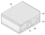
도 6은 본 발명의 바람직한 일실시예에 따른 반사형 편광자의 사시도로서, 기재(210)의 내부에 복수개의 랜덤 분산체(211)가 길이방향으로 신장되어 있으켜 스킨층(212)는 코어층의 상부에 형성된다. 이 경우 상기 랜덤 분산체(211)는 각각 다양한 방향으로 신장될 수 있지만, 바람직하게는 어느 일 방향으로 평행하여 신장되는 것이 유리하며, 보다 바람직하게는 외부광원에서 조사되는 광에 수직하는 방향으로 신장체간에 평행하게 신장되는 것이 광변조 효과를 극대화하는데 효과적이다. FIG. 6 is a perspective view of a reflective polarizer according to an exemplary embodiment of the present invention, in which a plurality of random dispersions 211 extend in a longitudinal direction of the substrate 210, such that the skin layer 212 is a core layer. It is formed at the top of the. In this case, the random dispersion 211 may be extended in various directions, respectively, but preferably, it is advantageously extended in parallel in one direction, and more preferably in a direction perpendicular to light irradiated from an external light source. Stretching parallel to the trunk is effective to maximize the light modulation effect.
본 발명의 바람직한 일구현예에 따르면, 기재내부에 포함되는 분산체(제1 성분)와 기재(제2 성분)간에 복굴절 계면이 형성될 수 있다. 구체적으로, 기재내부에 분산체를 포함하는 반사형 편광자에 있어서, 기재와 분산체간의 공간상의 X, Y 및 Z축에 따른 굴절률의 실질적인 일치 또는 불일치의 크기는 그 축에 따라 편광된 광선의 산란 정도에 영향을 미친다. 일반적으로, 산란능은 굴절률 불일치의 제곱에 비례하여 변화한다. 따라서, 특정 축에 따른 굴절률의 불일치의 정도가 더 클수록, 그 축에 따라 편광된 광선이 더 강하게 산란된다. 반대로, 특정 축에 따른 불일치가 작은 경우, 그 축에 따라 편광된 광선은 더 적은 정도로 산란된다. 어떤 축에 따라 기재의 굴절률이 분산체의 굴절률과 실질적으로 일치되는 경우, 이러한 축에 평행한 전기장으로 편광된 입사광은 분산체의 부분의 크기, 모양 및 밀도와 상관없이 산란되지 않고 분산체를 통과할 것이다. 또한, 그 축에 따른 굴절률이 실질적으로 일치되는 경우, 광선은 실질적으로 산란되지 않고 물체를 통해 통과한다. 보다 구체적으로, 제1편광(P파)는 기재와 분산체의 경계에 형성되는 복굴절 계면에 영향을 받지 않고 투과되나, 제2편광(S파)는 기재와 분산체간의 경계에 형성되는 복굴절성 계면에 영향을 받아 광의 변조가 일어난다. 이를 통해 P파는 투과되고 S파는 광의 산란, 반사 등의 광의 변조가 발생하게 되어 결국 편광의 분리가 이루어지게 되는 것이다. According to a preferred embodiment of the present invention, a birefringent interface may be formed between the dispersion (first component) and the substrate (second component) included in the substrate. Specifically, in a reflective polarizer including a dispersion inside the substrate, the magnitude of the substantial coincidence or mismatch of the refractive indices along the X, Y, and Z axes in space between the substrate and the dispersion is the scattering of the polarized light along that axis. Affects the degree. In general, the scattering power varies in proportion to the square of the refractive index mismatch. Thus, the greater the degree of mismatch in refractive index along a particular axis, the more strongly scattered light polarized along that axis. Conversely, when the mismatch along a particular axis is small, the light polarized along that axis is scattered to a lesser extent. If the refractive index of the substrate along a certain axis substantially matches the refractive index of the dispersion, incident light polarized with an electric field parallel to this axis passes through the dispersion without scattering regardless of the size, shape and density of the portion of the dispersion. something to do. Also, when the refractive indices along that axis are substantially coincident, the light beam passes through the object without being substantially scattered. More specifically, the first polarized light (P wave) is transmitted without being affected by the birefringent interface formed at the boundary between the substrate and the dispersion, while the second polarized light (S wave) is formed at the boundary between the substrate and the dispersion. The modulation of the light occurs due to the interface. Through this, the P wave is transmitted, and the S wave generates light modulation such as scattering and reflection of light, and thus, polarization is separated.
따라서, 상기 기재와 분산체는 복굴절 계면을 형성하여야 광변조 효과를 유발할 수 있으므로, 상기 기재가 광학적 등방성인 경우, 분산체는 복굴절성을 가질 수 있고, 반대로 상기 기재가 광학적으로 복굴절성을 갖는 경우에는 분산체는 광학적 등방성을 가질 수 있다. 구체적으로, 상기 분산체의 x축 방향의 굴절율이 nX1, y축 방향의 굴절율이 nY1 및 z축 방향의 굴절율이 nZ1이고, 기재의 굴절율이 nX2, nY2 및 nZ2일 때, nX1과 nY1 사이의 면내 복굴절이 발생할 수 있다. 더욱 바람직하게는 기재와 분산체의 X, Y, Z축 굴절율 중 적어도 어느 하나가 상이할 수 있으며, 보다 바람직하게는 신장축이 X축인 경우 Y축 및 Z축 방향에 대한 굴절율의 차이가 0.05 이하이고, X축향에 대한 굴절율의 차이가 0.1 이상일 수 있다. 한편 통상적으로 굴절율의 차이가 0.05 이하이면 정합으로 해석된다.Therefore, since the substrate and the dispersion may cause a photomodulation effect by forming a birefringent interface, when the substrate is optically isotropic, the dispersion may have birefringence and conversely, when the substrate is optically birefringent The dispersion may have optical isotropy. Specifically, when the refractive index of the dispersion is nX 1 in the x-axis direction, the refractive index in the y-axis direction is nY 1 and the refractive index in the z-axis direction is nZ 1 , and the refractive index of the substrate is nX 2 , nY 2 and nZ 2 , In-plane birefringence between nX 1 and nY 1 may occur. More preferably, at least one of the X, Y, and Z axis refractive indices of the substrate and the dispersion may be different, and more preferably, the difference in refractive index with respect to the Y and Z axis directions is 0.05 or less when the extension axis is the X axis. The difference in refractive index with respect to the X-axis may be 0.1 or more. On the other hand, if the difference in refractive index is 0.05 or less, it is usually interpreted as a match.
한편 본 발명에서 기재의 두께는 20 ~ 180㎛일 수 있으나 이에 제한되지 않으며 스킨층의 두께는 50 ~ 500㎛일 수 있으나 이에 제한되지 않는다. 또한 전체 분산체의 개수는 32인치를 기준으로 기재의 두께가 120㎛일 때 25,000,000 ~ 80,000,000 개일 수 있으나 이에 제한되지 않는다.Meanwhile, the thickness of the substrate in the present invention may be 20 to 180 μm, but is not limited thereto. The thickness of the skin layer may be 50 to 500 μm, but is not limited thereto. In addition, the total number of dispersions may be 25,000,000 to 80,000,000 when the thickness of the substrate is 120 μm based on 32 inches, but is not limited thereto.
도 6은 본 발명의 바람직한 일실시예에 따른 구조화된 표면층이 형성된 반사형 편광자의 사시도로서, 기재 내부에 복수개의 분산체가 길이방향으로 신장되어 있고 이들은 코어층을 형성한다. 이 경우 상기 분산체는 각각 다양한 방향으로 신장될 수 있지만, 바람직하게는 어느 일 방향으로 평행하여 신장되는 것이 유리하며, 보다 바람직하게는 외부광원에서 조사되는 광에 수직하는 방향으로 신장체간에 평행하게 신장되는 것이 광변조 효과를 극대화하는데 효과적이다. 상기 스킨층(212)의 일면(스킨층을 불포함하는 경우 기재의 일면)에 프라이머층(미도시)이 선택적으로 형성될 수 있다. 이를 통해 구조화된 표면층의 접착력, 외관, 전광특성의 개선할 수 있다. 이의 재료로는 아크릴, 에스테르, 우레탄 등을 사용할 수 있으나 이에 한정되지 않는다. 프라이머층은 다른 층에 비해 얇게 형성될 수 있고, 프라이머층의 두께를 조절하여, 광 투과율을 향상시킬 수 있고 이와 더불어 반사율을 낮출 수 있다.6 is a perspective view of a reflective polarizer having a structured surface layer according to a preferred embodiment of the present invention, in which a plurality of dispersions are elongated in the longitudinal direction and form a core layer. In this case, each of the dispersions may be elongated in various directions, but is preferably advantageously extended in parallel in one direction, more preferably in parallel to the elongated bodies in a direction perpendicular to the light irradiated from an external light source. Stretching is effective to maximize the light modulation effect. A primer layer (not shown) may be selectively formed on one surface of the skin layer 212 (one surface of the substrate when the skin layer is not included). This can improve the adhesion, appearance, and light properties of the structured surface layer. Its material may be acrylic, ester, urethane, and the like, but is not limited thereto. The primer layer may be thinner than other layers, and the thickness of the primer layer may be adjusted to improve light transmittance and to lower the reflectance.
이러한 프라이머층의 두께는 5nm 내지 300nm일 수 있다. 만일 프라이머층의 두께가 5nm 미만이면, 코어층과 구조화된 표면층간의 접착력이 미미할 수 있으며, 프라이머층의 두께가 300nm를 초과하면, 프라이머 처리시 얼룩이나 분자의 뭉침이 발생할 수 있다.The thickness of this primer layer may be 5nm to 300nm. If the thickness of the primer layer is less than 5 nm, the adhesion between the core layer and the structured surface layer may be insignificant. If the thickness of the primer layer exceeds 300 nm, staining or agglomeration of molecules may occur during the primer treatment.
한편, 본 발명의 반사형 편광자는 적어도 일면에 구조화된 표면층을 형성하여 집광효과를 극대화하고 표면에서 난반사를 방지하여 휘도를 현저하게 향상시킬 수 있다. 상기 구조화된 표면층은 기재상에 형성되거나 프라이머층 상에 형성될 수 잇다.On the other hand, the reflective polarizer of the present invention can form a structured surface layer on at least one surface to maximize the condensing effect and prevent diffuse reflection on the surface to significantly improve the brightness. The structured surface layer can be formed on a substrate or on a primer layer.
본 발명에서 적용될 수 있는 구조화된 표면층은 집광효과를 향상시킬 수 있는 구조로서 바람직하게는 미세패턴층일 수 있다. 이 경우 적용될 수 있는 미세패턴은 프리즘, 렌티큘러, 마이크로 렌즈, 삼각뿔 및 피라미드 패턴으로 구성되는 군으로부터 선택되는 어느 하나 이상일 수 있으며, 이들 각각이 단독으로 패턴을 형성하거나 조합되어 형성될 수 있다.The structured surface layer that can be applied in the present invention is preferably a fine pattern layer as a structure capable of improving the light collecting effect. In this case, the micropattern that can be applied may be any one or more selected from the group consisting of prisms, lenticulars, microlenses, triangular pyramids, and pyramid patterns, each of which may be formed by combining or forming a pattern alone.
도 8에서는 반사형 편광자의 기재층의 일면에 스킨층(212) 및 렌티큘러 패턴층(213)이 형성되어 있으며, 이를 중심으로 설명하면 렌티큘러의 높이(a)는 10 ~ 50㎛일 수 있다. 만일 렌티큘러 패턴의 높이가 10㎛ 미만이면 패턴층 구현이 어려운 문제가 발생할 수 있고 50㎛를 초과하면 광의 전반사량 증가로 인해 휘도가 감소하는 문제가 발생할 수 있다.In FIG. 8, the skin layer 212 and the lenticular pattern layer 213 are formed on one surface of the base layer of the reflective polarizer. The height a of the lenticular may be 10 to 50 μm. If the height of the lenticular pattern is less than 10 μm, it may be difficult to implement the pattern layer. If the height of the lenticular pattern exceeds 50 μm, the luminance may decrease due to an increase in total reflection of light.
또한, 렌티큘러의 피치(b)는 20 ~ 100㎛일 수 있다. 만일 렌티큘러 패턴의 피치가 20㎛ 미만이면 단위면적당 필름의 골부분의 증가로 인하여 렌즈 형상의 집광효과가 다소 떨어지며, 형상가공의 정밀도의 한계와 패턴형상이 지나치게 좁아 패턴 구현이 어려운 문제가 발생할 수 있고 100㎛를 초과하면 패턴구조물과 패널간의 모아레 발생 가능성이 매우 커지게 된다. In addition, the pitch b of the lenticular may be 20 to 100 μm. If the pitch of the lenticular pattern is less than 20 μm, the condensing effect of the lens shape is somewhat decreased due to the increase of the valley portion of the film per unit area, and the limitation of the precision of the shape processing and the pattern shape are too narrow may cause a problem of difficult to implement the pattern. If the thickness exceeds 100 μm, the possibility of moiré between the pattern structure and the panel becomes very large.
한편, 렌티큘러 렌즈 당, 타원단면의 단축반경을 a라 하고, 장축반경을 b라 정의할 때, 장축/단축(b/a)의 비가 1.0 내지 3.0을 충족한다. 장축/단축(b/a)의 비율이 상기 범위를 벗어나면, 복굴절 편광층을 통과하는 광에 대한 휘선은폐 효율이 떨어지는 문제가 발생할 수 있다.On the other hand, when the short axis radius of the elliptical section is defined as a and the long axis radius is defined as b per lenticular lens, the ratio of the major axis / short axis b / a satisfies 1.0 to 3.0. When the ratio of the long axis / short axis (b / a) is out of the above range, there may occur a problem that the linear concealment efficiency with respect to light passing through the birefringent polarization layer is inferior.
또한, 렌티큘러 렌즈의 높이 h를 정의함에 있어서, 렌즈 하단부 양 끝점에서의 접선각도 α는 30∼80도 사이를 충족해야 한다. 이때, α가 30도보다 작으면, 휘선은폐 효율이 떨어지고, 80도보다 크면, 렌즈패턴의 제작이 어려워지는 문제가 있다. 렌티큘러 렌즈의 단면형상이 삼각형일 경우에는 휘선은폐 효과를 위해서 꼭지점 각도 θ가 90∼120도를 충족하는 것이 좋다.Further, in defining the height h of the lenticular lens, the tangential angle α at both ends of the lower end of the lens must satisfy 30 to 80 degrees. At this time, when α is smaller than 30 degrees, the concealment efficiency of the bright line is inferior, and when α is larger than 80 degrees, there is a problem that the production of the lens pattern becomes difficult. If the cross-sectional shape of the lenticular lens is a triangle, it is preferable that the vertex angle θ satisfies 90 to 120 degrees for the concealed light effect.
한편, 렌티큘러 형상은 도 8과 같이 동일한 높이와 피치를 갖는 패턴으로 형성되거나, 도 9와 같이 상이한 높이와 피치를 갖는 렌티큘러 패턴들이 혼재될 수 있다.Meanwhile, the lenticular shape may be formed in a pattern having the same height and pitch as shown in FIG. 8, or lenticular patterns having different heights and pitches may be mixed as shown in FIG. 9.
도 10은 반사형 편광자의 일면에 마이크로 렌즈 패턴층이 형성된 것으로서, 이를 중심으로 설명하면 마이크로 렌즈의 높이는 10 ~ 50㎛일 수 있다. 만일 마이크로 렌즈 패턴의 높이가 10㎛ 미만이면 집광효과가 다소 떨어지며 패턴 구현도 어려운 문제가 발생할 수 있고 50㎛를 초과하면 모아레현상이 발생하기 쉽고, 화상에 패턴이 보이는 문제가 발생할 수 있다.FIG. 10 illustrates that a microlens pattern layer is formed on one surface of a reflective polarizer. Referring to FIG. 10, the height of the microlens may be 10 to 50 μm. If the height of the micro-lens pattern is less than 10㎛ may cause a problem of light condensing slightly and difficult to implement the pattern, if it exceeds 50㎛ may cause a moire phenomenon, a problem that the pattern is visible on the image.
또한, 마이크로 렌즈의 직경은 20 ~ 100㎛일 수 있다. 바람직하게는 30 ~ 60㎛일 수 있다. 상기 범위에서 외관특성이 양호하면서 마이크로 렌즈의 집광기능 및 광확산 특성이 우수할 수 있고 실제 제작이 용이할 수 있다. 만일 마이크로 렌즈 패턴의 직경이 20㎛ 미만이면 유효하지 않은 각도에서 입사되는 입사광에 대하여 낮은 집광효율을 보이는 문제가 발생할 수 있고 100㎛를 초과하면 수직광에 대한 집광효율이 저하되며, 또한 모아레 현상 문제가 발생할 수 있다.In addition, the diameter of the micro lens may be 20 ~ 100㎛. Preferably it may be 30 ~ 60㎛. While the appearance characteristics are good in the above range, the light condensing function and the light diffusing characteristics of the microlenses may be excellent and the actual manufacturing may be easy. If the diameter of the microlens pattern is less than 20 μm, a problem may occur that shows a low light collection efficiency for incident light incident from an invalid angle. If the diameter of the micro lens pattern exceeds 100 μm, the light collection efficiency for vertical light may be deteriorated. May occur.
한편, 마이크로 렌즈 패턴층 역시 도 10과 같이 동일한 높이와 직경을 갖는 패턴으로 형성되거나, 도 11과 같이 상이한 높이와 직경을 갖는 마이크로 렌즈 패턴들이 혼재될 수 있다. 이러한 마이크로 렌즈 패턴은 렌즈의 밀집도(Density), 함침도(Aspect Ratio)에 따라 광특성이 많이 차이가 있기 때문에 밀집도를 최대한 올리며, 함침도는 1/2을 갖는 것이 이상적이다.Meanwhile, the microlens pattern layer may also be formed in a pattern having the same height and diameter as shown in FIG. 10, or microlens patterns having different heights and diameters may be mixed as shown in FIG. 11. Since the microlens pattern has a large difference in optical characteristics according to the density of the lens and the degree of impregnation, the microlens pattern may have the highest density, and the degree of impregnation should be 1/2.
도 12에서는 반사형 편광자의 일면에 프리즘 패턴층(213)이 형성되어 있으며, 이를 중심으로 설명하면 프리즘의 높이(a)는 10 ~ 50㎛일 수 있다. 만일 프리즘 패턴의 높이가 10㎛ 미만이면 프리즘 패턴부의 형상을 제조할 때 베이스 필름이 압력에 손상을 받을 수 있고, 50㎛를 초과하면 광원으로 입사되는 광의 투과율이 저하되는 문제가 발생할 수 있다.In FIG. 12, the prism pattern layer 213 is formed on one surface of the reflective polarizer, and the prism height a may be about 10 μm to about 50 μm. If the height of the prism pattern is less than 10 μm, the base film may be damaged by pressure when manufacturing the shape of the prism pattern part. If the height of the prism pattern exceeds 50 μm, the transmittance of light incident on the light source may be reduced.
또한, 프리즘의 피치(b)는 20 ~ 100㎛일 수 있다. 만일 프리즘 패턴의 피치가 20㎛ 미만이면 인각이 잘 안되며, 패턴층 구현 및 제조공정이 복잡한 문제가 발생할 수 있고 100㎛를 초과하면 모아레 현상이 발생하기 쉽고, 화상에 패턴이 보이는 문제가 발생할 수 있다.In addition, the pitch b of the prism may be 20 to 100 μm. If the pitch of the prism pattern is less than 20µm, the engraving is not good, and the pattern layer implementation and manufacturing process may have complicated problems. If it exceeds 100µm, the moire phenomenon is likely to occur, and the pattern may be seen on the image. .
한편, 프리즘 형상은 도 12와 같이 동일한 높이와 피치를 갖는 패턴으로 형성되거나, 도 13과 같이 상이한 높이와 피치를 갖는 프리즘 패턴들이 혼재될 수 있다. 이러한 프리즘 패턴은 베이스 필름 보다 굴절률이 높은 물질로 이루어질 수 있는데, 이는 베이스 필름의 굴절률이 더 높은 경우 베이스 필름의 후면으로 입사된 광의 일부가 프리즘 패턴의 표면에서 전반사 되어 프리즘 구조로 입사되지 못할 수 있기 때문이다. 상기 프리즘 형상은 바람직하게는 선형 프리즘 형상이며 수직 단면은 삼각형이며 상기 삼각형은 하부면과 대향하는 꼭지점이 60 ~ 110°의 각을 이루는 것이 바람직하다.On the other hand, the prism shape may be formed in a pattern having the same height and pitch as shown in FIG. 12, or the prism patterns having different heights and pitches as shown in FIG. 13 may be mixed. The prism pattern may be formed of a material having a higher refractive index than that of the base film. When the refractive index of the base film is higher, a part of the light incident to the rear surface of the base film may be totally reflected at the surface of the prism pattern and thus may not be incident to the prism structure. Because. Preferably, the prism shape is a linear prism shape, the vertical cross section is triangular, and the triangle forms an angle of 60 to 110 ° with a vertex facing the lower surface.
구조화된 표면층의 재질은 바람직하게는 열경화성 또는 광경화성 아크릴 수지 등을 포함하는 고분자 수지가 사용될 수 있다. 예를 들어, 프리즘 패턴는 불포화 지방산 에스테르, 방향족 비닐 화합물, 불포화 지방산과 그 유도체, 메타크릴나이트릴과 같은 비닐 시아나이드 화합물 등을 사용할 수 있으며, 구체적으로는 우레타닉 아크릴레이트, 메타크릴릭 아크릴레이트 수지 등이 사용될 수 있다. 또한 구조화된 표면층은 반사형 편광자보다 굴절률이 높은 물질로 이루어질 수 있다.The material of the structured surface layer may preferably be a polymer resin including a thermosetting or photocurable acrylic resin or the like. For example, as the prism pattern, unsaturated fatty acid esters, aromatic vinyl compounds, unsaturated fatty acids and derivatives thereof, vinyl cyanide compounds such as methacrylonitrile, and the like may be used. Specifically, urethane acrylates and methacryl acrylates may be used. Resins and the like can be used. The structured surface layer may also be made of a material having a higher refractive index than the reflective polarizer.
다음으로 랜던분산형 반사형 편광자의 제조방법을 설명한다. Next, a manufacturing method of the random scattering reflective polarizer will be described.
먼저, (1) 단계로서, 기재성분, 분산체 성분 및 스킨층 성분을 압출부에 공급한다. 상기 기재 성분은 통상적인 분산체가 분산된 반사편광자에서 사용되는 것이라면 제한없이 사용될 수 있으며, 바람직하게는 폴리에틸렌나프탈레이트(PEN), 코폴리에틸렌나프탈레이트(co-PEN), 폴리에틸렌테레프탈레이트(PET),폴리카보네이트(PC), 폴리카보네이트(PC) 얼로이, 폴리스타이렌(PS), 내열폴리스타이렌(PS), 폴리메틸메타아크릴레이트(PMMA), 폴리부틸렌테레프탈레이트(PBT), 폴리프로필렌(PP), 폴리에틸렌(PE), 아크릴로니트릴부타디엔스티렌(ABS), 폴리우레탄(PU),폴리이미드(PI),폴리비닐클로라이드(PVC), 스타이렌아크릴로니트릴혼합(SAN),에틸렌초산비닐(EVA), 폴리아미드(PA), 폴리아세탈(POM), 페놀, 에폭시(EP), 요소(UF), 멜라닌(MF), 불포화포리에스테르(UP), 실리콘(SI) 및 사이크로올레핀폴리머를 사용할 수 있으며 보다 바람직하게는 PEN일 수 있다.First, as step (1), the base component, the dispersion component, and the skin layer component are supplied to the extrusion unit. The substrate component may be used without limitation as long as it is used in a reflective polarizer in which a conventional dispersion is dispersed. Preferably, polyethylene naphthalate (PEN), copolyethylene naphthalate (co-PEN), polyethylene terephthalate (PET), and poly Carbonate (PC), polycarbonate (PC) alloy, polystyrene (PS), heat-resistant polystyrene (PS), polymethyl methacrylate (PMMA), polybutylene terephthalate (PBT), polypropylene (PP), polyethylene ( PE), acrylonitrile butadiene styrene (ABS), polyurethane (PU), polyimide (PI), polyvinyl chloride (PVC), styrene acrylonitrile mixture (SAN), ethylene vinyl acetate (EVA), polyamide (PA), polyacetal (POM), phenol, epoxy (EP), urea (UF), melanin (MF), unsaturated polyesters (UP), silicone (SI) and cycloolefin polymers may be used and more preferably May be PEN.
상기 분산체 성분은 통상적으로 분산체가 분산된 반사편광자에서 사용되는 것이라면 제한없이 사용될 수 있으며, 바람직하게는 폴리에틸렌나프탈레이트(PEN), 코폴리에틸렌나프탈레이트(co-PEN), 폴리에틸렌테레프탈레이트(PET), 폴리카보네이트(PC), 폴리카보네이트(PC) 얼로이, 폴리스타이렌(PS), 내열폴리스타이렌(PS), 폴리메틸메타아크릴레이트(PMMA), 폴리부틸렌테레프탈레이트(PBT), 폴리프로필렌(PP), 폴리에틸렌(PE), 아크릴로니트릴부타디엔스티렌(ABS), 폴리우레탄(PU),폴리이미드(PI), 폴리비닐클로라이드(PVC), 스타이렌아크릴로니트릴혼합(SAN), 에틸렌초산비닐(EVA), 폴리아미드(PA), 폴리아세탈(POM), 페놀, 에폭시(EP), 요소(UF), 멜라닌(MF), 불포화포리에스테르(UP), 실리콘(SI) 및 사이크로올레핀폴리머를 단독 또는 혼합하여 사용할 수 있으며 보다 바람직하게는 디메틸-2,6-나프탈렌 디카르복실레이트, 디메틸테레프탈레이트 및 에틸렌글리콜, 싸이크로헥산디메탄올(CHDM) 등의 단량체들이 적절하게 중합된 co-PEN일 수 있다.The dispersion component may be used without limitation as long as the dispersion component is used in a reflective polarizer in which the dispersion is dispersed. Preferably, polyethylene naphthalate (PEN), copolyethylene naphthalate (co-PEN), polyethylene terephthalate (PET), Polycarbonate (PC), Polycarbonate (PC) Alloy, Polystyrene (PS), Heat Resistant Polystyrene (PS), Polymethylmethacrylate (PMMA), Polybutylene Terephthalate (PBT), Polypropylene (PP), Polyethylene (PE), acrylonitrile butadiene styrene (ABS), polyurethane (PU), polyimide (PI), polyvinyl chloride (PVC), styrene acrylonitrile mixture (SAN), ethylene vinyl acetate (EVA), poly Amide (PA), polyacetal (POM), phenol, epoxy (EP), urea (UF), melanin (MF), unsaturated polyester (UP), silicone (SI) and cycloolefin polymer And more preferably May be co-PEN in which monomers such as dimethyl-2,6-naphthalene dicarboxylate, dimethyl terephthalate and ethylene glycol, cyclohexanedimethanol (CHDM) are properly polymerized.
상기 스킨층 성분은 통상적으로 사용되는 성분을 사용할 수 있으나 바람직하게는 반사편광자에서 사용되는 것이라면 제한없이 사용될 수 있으며, 바람직하게는 폴리에틸렌나프탈레이트(PEN), 코폴리에틸렌나프탈레이트(co-PEN), 폴리에틸렌테레프탈레이트(PET), 폴리카보네이트(PC), 폴리카보네이트(PC) 얼로이, 폴리스타이렌(PS), 내열폴리스타이렌(PS), 폴리메틸메타아크릴레이트(PMMA), 폴리부틸렌테레프탈레이트(PBT), 폴리프로필렌(PP), 폴리에틸렌(PE), 아크릴로니트릴부타디엔스티렌(ABS), 폴리우레탄(PU),폴리이미드(PI),폴리비닐클로라이드(PVC), 스타이렌아크릴로니트릴혼합(SAN),에틸렌초산비닐(EVA), 폴리아미드(PA), 폴리아세탈(POM), 페놀, 에폭시(EP), 요소(UF), 멜라닌(MF), 불포화포리에스테르(UP), 실리콘(SI) 및 사이크로올레핀폴리머를 단독 또는 혼합하여 사용할 수 있으며 보다 바람직하게는 디메틸-2,6-나프탈렌 디카르복실레이트, 디메틸테레프탈레이트 및 에틸렌글리콜, 싸이크로헥산디메탄올(CHDM) 등의 단량체들이 적절하게 중합된 co-PEN일 수 있다.The skin layer component may be used a component that is commonly used but preferably may be used without limitation as long as it is used in the reflective polarizer, preferably polyethylene naphthalate (PEN), copolyethylene naphthalate (co-PEN), polyethylene Terephthalate (PET), Polycarbonate (PC), Polycarbonate (PC) Alloy, Polystyrene (PS), Heat-Resistant Polystyrene (PS), Polymethylmethacrylate (PMMA), Polybutylene Terephthalate (PBT), Poly Propylene (PP), Polyethylene (PE), Acrylonitrile Butadiene Styrene (ABS), Polyurethane (PU), Polyimide (PI), Polyvinyl Chloride (PVC), Styrene Acrylonitrile Mixture (SAN), Ethylene Acetic Acid Vinyl (EVA), polyamide (PA), polyacetal (POM), phenol, epoxy (EP), urea (UF), melanin (MF), unsaturated polyester (UP), silicone (SI) and cycloolefin polymer Alone or mixed Can and may be more preferably, dimethyl 2,6-naphthalenedicarboxylate, dimethyl terephthalate and ethylene glycol, Im chroman-hexane dimethanol (CHDM), such as the monomers are suitably polymerized co-PEN.
한편, 상기 기재성분과 분산체 성분을 개별적으로 독립된 압출부들에 공급할 수 있으며 이 경우 압출부는 2개 이상으로 구성될 수 있다. 또한 폴리머들이 섞이지 않도록 별도의 공급로 및 분배구를 포함하는 하나의 압출부에 공급하는 것 역시 본 발명에 포함된다. 상기 압출부는 익스트루더일 수 있으며, 이는 고체상의 공급된 폴리머들을 액상으로 전환시킬 있도록 가열수단 등을 더 포함할 수 있다.On the other hand, the base component and the dispersion component may be supplied to the independent extrusion parts separately, in this case, the extrusion part may be composed of two or more. Also included in the present invention is a feed to one extruder comprising a separate feed passage and distributor so that the polymers do not mix. The extruder may be an extruder, which may further include heating means or the like to convert the supplied polymers into a liquid phase.
기재성분의 내부에 분산체 성분이 배열될 수 있도록 폴리머 흐름성 차이가 있도록 점도를 차이가 있도록 설계하며, 바람직하게는 기재 성분이 흐름성이 분산체 성분보다 좋도록 한다. 다음 기재 성분과 분산체 성분이 믹싱존과 메시필터존을 통과하면서 기재 내에 분산체 성분이 점성에 차이를 통해 랜덤하게 배열된다.The viscosity is so designed that there is a difference in polymer flow so that the dispersion component can be arranged inside the base component, and the base component is preferably made to have better flowability than the dispersion component. Next, the dispersion component is randomly arranged in the substrate through the difference in viscosity while the substrate component and the dispersion component pass through the mixing zone and the mesh filter zone.
그 뒤 다음, 상기 제조된 코어층의 적어도 일면을 압출부에서 이송된 스킨층 성분을 합지할 수 있다. 바람직하게는 상기 스킨층 성분은 상기 코어층의 양면에 모두 합지될 수 있다. 양면에 스킨층이 합지되는 경우 상기 스킨층의 재질 및 두께는 서로 동일하거나 상이할 수 있다. Thereafter, at least one surface of the prepared core layer may be laminated with the skin layer component transferred from the extruder. Preferably, the skin layer component may be laminated on both surfaces of the core layer. When the skin layer is laminated on both surfaces, the material and the thickness of the skin layer may be the same or different from each other.
다음, 기재 내부에 포함된 분산체 성분이 랜덤하게 배열될 수 있도록 흐름제어부에서 퍼짐을 유도한다. 구체적으로 도 14는 본 발명에 적용될 수 있는 바람직한 흐름제어부의 일종인 코트-행거 다이의 단면도이고, 도 15는 측면도이다. 이를 통해 기재의 퍼짐정도를 적절하게 조절하여 분산체 성분의 단면적의 크기 및 배열을 랜덤하게 조절할 수 있다. 도 14에서 유로를 통해 이송된 스킨층이 합지된 기재가 코트-행거 다이에서 좌우로 넓게 퍼지므로 내부에 포함된 분산체 성분 역시 좌우로 넓게 퍼지게 된다. Next, spreading is induced in the flow control unit so that the dispersion components included in the substrate may be randomly arranged. Specifically, FIG. 14 is a cross-sectional view of a coat-hanger die which is a kind of preferred flow control unit that can be applied to the present invention, and FIG. 15 is a side view. Through this, the spreading degree of the substrate may be appropriately adjusted to randomly adjust the size and arrangement of the cross-sectional area of the dispersion component. In FIG. 14, since the substrate on which the skin layer transferred through the flow path is laminated spreads from side to side in the coat-hanger die, the dispersion component contained therein also spreads from side to side.
본 발명의 바람직한 일구현예에 따르면, 흐름제어부에서 이송된 퍼짐이 유도된 편광자를 냉각 및 평활화하는 단계, 상기 평활화 단계를 거친 편광자를 연신하는 단계; 및 상기 연신된 편광자를 열고정하는 단계를 더 포함할 수 있다.According to a preferred embodiment of the present invention, the step of cooling and smoothing the polarizer induced the spread induced in the flow control unit, stretching the polarizer after the smoothing step; And heat setting the stretched polarizer.
먼저, 흐름제어부에서 이송된 편광자를 냉각 및 평활화하는 단계로서 통상의 반사 편광자의 제조에서 사용되던 냉각하여 이를 고형화하고 이후 캐스팅 롤공정 등을 통해 평활화 단계를 수행할 수 있다.First, as a step of cooling and smoothing the polarizer transferred from the flow control unit, the cooling used in the manufacture of the conventional reflective polarizer is solidified, and then the smoothing step may be performed through a casting roll process or the like.
이후, 상기 평활화 단계를 거친 편광자를 연신하는 공정을 거친다. 상기 연신은 통상의 반사 편광자의 연신공정을 통해 수행될 수 있으며, 이를 통해 기재성분과 분산체 성분간의 굴절율 차이를 유발하여 계면에서 광변조 현상을 유발할 수 있고, 상기 퍼짐유도된 제1 성분(분산체 성분)은 연신을 통해 종횡비가 더욱 줄어들게 된다. 이를 위하여 바람직하게는 연신공정은 일축연신 또는 이축연신을 수행할 수 있으며, 보다 바람직하게는 일축연신을 수행할 수 있다. 일축연신의 경우 연신방향은 제1 성분 길이방향으로 연신을 수행할 수 있다. 또한 연신비는 3 ~ 12배 일 수 있다. 한편, 등방성 재료를 복굴절성으로 변화시키는 방법은 통상적으로 알려진 것이며 예를 들어 적절한 온도 조건 하에서 연신시키는 경우, 분산체 분자들은 배향되어 재료는 복굴절성으로 될 수 있다.Thereafter, a process of stretching the polarizer after the smoothing step is performed. The stretching may be performed through a stretching process of a conventional reflective polarizer, thereby causing a difference in refractive index between the base component and the dispersion component, causing a light modulation phenomenon at the interface, and spreading the first component (dispersion). Sieve components), the aspect ratio is further reduced through stretching. For this purpose, preferably, the stretching step may be performed uniaxially or biaxially, and more preferably, uniaxially. In the case of uniaxial stretching, the stretching direction may be performed in the longitudinal direction of the first component. In addition, the draw ratio may be 3 to 12 times. On the other hand, methods for changing an isotropic material to birefringence are commonly known and, for example, when drawn under appropriate temperature conditions, the dispersion molecules can be oriented so that the material becomes birefringent.
다음, 상기 연신된 편광자를 열고정하는 단계를 거쳐 최종적인 반사형 편광자를 제조할 수 있다. 상기 열고정은 통상의 방법을 통해 열고정될 수 있으며, 바람직하게는 180 ~ 200℃ 에서 0.1 ~ 3분 동안 IR 히터를 통해 수행될 수 있다.Next, the final reflective polarizer may be manufactured by heat setting the stretched polarizer. The heat setting may be heat setting through a conventional method, preferably may be performed through an IR heater for 0.1 to 3 minutes at 180 ~ 200 ℃.
다음, (2) 단계로서 제조된 반사형 편광자(코어층 또는 스킨층)의 적어도 일면에 구조화된 표면층을 형성한다. 이 때 구조화된 표면층의 형성을 보다 용이하게 하기 위하여 코어층(또는 스킨층)의 적어도 일면에 프라이머 층을 더 형성할 수 있다. 이를 통해 구조화된 표면층의 접착력, 외관, 전광특성의 개선할 수 있다. 이의 재료로는 아크릴, 에스테르, 우레탄 등을 사용할 수 있으나 이에 한정되지 않는다. 프라이머층은 다른 층에 비해 얇게 형성될 수 있고, 프라이머층의 두께를 조절하여, 광 투과율을 향상시킬 수 있고 이와 더불어 반사율을 낮출 수 있다.Next, a structured surface layer is formed on at least one surface of the reflective polarizer (core layer or skin layer) manufactured as step (2). In this case, in order to more easily form the structured surface layer, a primer layer may be further formed on at least one surface of the core layer (or skin layer). This can improve the adhesion, appearance, and light properties of the structured surface layer. Its material may be acrylic, ester, urethane, and the like, but is not limited thereto. The primer layer may be thinner than other layers, and the thickness of the primer layer may be adjusted to improve light transmittance and to lower the reflectance.
이러한 프라이머층의 두께는 5nm 내지 300nm일 수 있다. 만일 프라이머층의 두께가 5nm 미만이면, 코어층과 구조화된 표면층간의 접착력이 미미할 수 있으며, 프라이머층의 두께가 300nm를 초과하면, 프라이머 처리시 얼룩이나 분자의 뭉침이 발생할 수 있다.The thickness of this primer layer may be 5nm to 300nm. If the thickness of the primer layer is less than 5 nm, the adhesion between the core layer and the structured surface layer may be insignificant. If the thickness of the primer layer exceeds 300 nm, staining or agglomeration of molecules may occur during the primer treatment.
한편, 본 발명의 반사형 편광자는 적어도 일면에 구조화된 표면층을 형성하여 집광효과를 극대화하고 표면에서 난반사를 방지하여 휘도를 현저하게 향상시킬 수 있다. On the other hand, the reflective polarizer of the present invention can form a structured surface layer on at least one surface to maximize the condensing effect and prevent diffuse reflection on the surface to significantly improve the brightness.
본 발명에서 적용될 수 있는 구조화된 표면층은 집광효과를 향상시킬 수 있는 구조로서 바람직하게는 미세패턴층일 수 있다. 이 경우 적용될 수 있는 미세패턴은 프리즘, 렌티큘러, 마이크로 렌즈, 삼각뿔 및 피라미드 패턴으로 구성되는 군으로부터 선택되는 어느 하나 이상일 수 있으며, 이들 각각이 단독으로 패턴을 형성하거나 조합되어 형성될 수 있다. 또한 단독으로 패턴이 형성되는 경우에도 패턴이 일정하거나 높이, 피치 등이 상이하게 배열될 수 있다.The structured surface layer that can be applied in the present invention is preferably a fine pattern layer as a structure capable of improving the light collecting effect. In this case, the micropattern that can be applied may be any one or more selected from the group consisting of prisms, lenticulars, microlenses, triangular pyramids, and pyramid patterns, each of which may be formed by combining or forming a pattern alone. In addition, even when the pattern is formed alone, the pattern may be arranged in a constant or different height, pitch, and the like.
구조화된 표면층의 재질은 바람직하게는 열경화성 또는 광경화성 아크릴 수지 등을 포함하는 고분자 수지가 사용될 수 있다. 예를 들어, 프리즘 패턴은 불포화 지방산 에스테르, 방향족 비닐 화합물, 불포화 지방산과 그 유도체, 메타크릴나이트릴과 같은 비닐 시아나이드 화합물 등을 사용할 수 있으며, 구체적으로는 우레타닉 아크릴레이트, 메타크릴릭 아크릴레이트 수지 등이 사용될 수 있다. 또한 구조화된 표면층은 반사형 편광자보다 굴절률이 높은 물질로 이루어질 수 있다.The material of the structured surface layer may preferably be a polymer resin including a thermosetting or photocurable acrylic resin or the like. For example, the prism pattern may be unsaturated fatty acid esters, aromatic vinyl compounds, unsaturated fatty acids and derivatives thereof, vinyl cyanide compounds such as methacrylonitrile, and the like, and specifically, urethane acrylate and methacrylic acrylic Rate resins and the like can be used. The structured surface layer may also be made of a material having a higher refractive index than the reflective polarizer.
한편, 상기 미세패턴층은 패턴형성용 몰드필름을 통해 제조될 수 있다. 패턴형성용 몰드필름의 재질로는 투명하고 유연성이 있으며 소정의 인장 강도 및 내구성이 있는 필름을 사용할 수 있으며, PET 필름을 사용하는 것이 바람직하다. On the other hand, the fine pattern layer may be manufactured through a mold film for pattern formation. As a material of the mold film for pattern formation, a film having a transparent, flexible, predetermined tensile strength and durability may be used, and it is preferable to use a PET film.
이 경우 본 발명의 바람직한 일구현예에 따르면, 상기 (2) 단계는 2-1) 상기 구조화된 표면층의 역상인 패턴이 일면에 성형된 마스터롤에 반사형 편광자를 밀착 이송시키고, 상기 마스터롤의 패턴면 또는 상기 코어층면에 용융된 고분자수지를 도포하는 단계; 및 2-2) 상기 고분자수지가 상기 마스터롤의 패턴면 상에서 가압 성형되는 동안 UV 또는 열을 조사하여 상기 고분자수지를 UV경화시키고 이를 분리하는 단계;를 포함할 수 있다.In this case, according to a preferred embodiment of the present invention, the step (2) is 2-1) to transfer the reflective polarizer in close contact with the master roll formed on one surface of the reversed pattern of the structured surface layer, Applying a molten polymer resin to a pattern surface or the core layer surface; And 2-2) UV curing and separating the polymer resin by UV or heat while the polymer resin is press-molded on the patterned surface of the master roll.
본 발명의 바람직한 또 다른 일실시예에 따르면, 상기 2-2) 단계 이후 재차 UV 또는 열을 조사하여 상기 고분자수지를 2차 경화시킬 수 있다.According to another preferred embodiment of the present invention, after the step 2-2) may be irradiated with UV or heat again to cure the polymer resin secondary.
구체적으로 도 16은 본 발명의 바람직한 일실시예에 따른 미세패턴 형성공정의 개략도이며 도 17은 도 16의 성형부의 세부구조를 나타낸 단면도이다. 도 16에서 반사형 편광자(770)는 스타트롤(755)에서 풀려 나오면서 가이드롤(754)을 지나 적외선램프(751)을 거치게 된다. 이 과정에서 상기 반사형 편광자(770)는 적외선램프의 적외선에 의해 표면 개질되어 상기 패턴형성층(771)과의 부착성이 좋아 지게 된다. 스타트롤(755)을 떠난 반사형 편광자(770)는 패턴가이드롤(764)를 거쳐 마스터롤(705)에 인입될 때, 주입부(742)로부터 상기 마스터롤(705)의 패턴면에는 패턴형성층(771)재료, 패턴층 고분자가 도포되어 기재층(770)과 합쳐지게 된다. 이 과정에서 상기 레진은 상온에서 용융된 수지이며, 상기 마스터롤(705)의 하부에 비치된 1차 UV경화장치(752)에서 조사되는 1차 UV광으로 인해 1 차 경화될 수 있다. 이 때 상기 경화장치(752) 주변의 온도는 20~ 30℃ 이고, 상기 레진이 경화하면서 발생하는 열의 온도는 40~80℃로서 상기 레진의 유리전이온도(Tg: 고분자수지Specifically, FIG. 16 is a schematic diagram of a micropattern forming process according to an exemplary embodiment of the present invention, and FIG. 17 is a cross-sectional view illustrating a detailed structure of the molding part of FIG. 16. In FIG. 16, the reflective polarizer 770 passes through the infrared lamp 751 through the guide roll 754 while being released from the start trol 755. In this process, the reflective polarizer 770 is surface-modified by the infrared rays of the infrared lamp, so that the adhesion to the pattern forming layer 771 is improved. When the reflective polarizer 770 leaving the start trol 755 is introduced into the master roll 705 via the pattern guide roll 764, the pattern forming layer is formed on the pattern surface of the master roll 705 from the injection portion 742. (771) A material and a pattern layer polymer are coated to merge with the base layer 770. In this process, the resin is a resin melted at room temperature, and may be primarily cured due to the primary UV light irradiated from the primary UV curing device 752 disposed under the master roll 705. At this time, the temperature around the curing apparatus 752 is 20 ~ 30 ℃, the temperature of heat generated while the resin is cured is 40 ~ 80 ℃ as the glass transition temperature (Tg: polymer resin) of the resin
에서 고체에서 액체로 완전한 상 변화를 거치기 전에 부드러운 고무처럼 변화된 특성을 나타내는 온도) 근처가 될 수 있다. 상기 유리전이 상태에서 마스터롤 표면의 패턴모양을 완전히 복사한 패턴형성층(771)은 다시 패턴가이드롤(764)을 지나 빠져나오면서 반사형 편광자(770)와 패턴형성층(771)이 합체된 패턴이 형성된 반사형 편광자(772)로 성형되어 가이드롤(754)를 지나 피니쉬롤(756)에 감기게 된다.Temperature at which its properties change like a soft rubber before undergoing a complete phase change from solid to liquid. In the glass transition state, the pattern forming layer 771 completely copying the pattern of the surface of the master roll exits through the pattern guide roll 764 and forms a pattern in which the reflective polarizer 770 and the pattern forming layer 771 are combined. It is molded into a reflective polarizer 772 and wound around the guide roll 754 to the finish roll 756.
도 16과 같이 2차례에 걸쳐 UV를 조사하여 제작된 턴이 형성된 반사형 편광자(772)의 단면은 마스터롤(705)의 단면에 상반되는 형태의 면으로써 예를 들어 마스터롤이 음각의 인그레이빙(engraved)면 이라면 턴이 형성된 반사형 편광자(772)는 양각의 엠보싱(embossed)면이 된다. As shown in FIG. 16, the cross-section of the turn-shaped reflective polarizer 772 formed by irradiating UV over two times is a surface opposite to the cross-section of the master roll 705. If it is an engraved surface, the turn-shaped reflective polarizer 772 becomes an embossed surface of the relief.
이 경우 본 발명의 바람직한 일구현예에 따르면, 상기 (2) 단계는 a) 상기 반사형 편광자를 이송시키는 단계; b) 상기 구조화된 표면층의 역상인 패턴이 일면에 성형된 패턴형성용 몰드필름을 이송시키는 단계; c) 상기 반사형 편광자의 일면과 상기 패턴형성용 몰드필름 중 상기 패턴이 성형된 일면을 밀착시키는 단계; d) 상기 반사형 편광자와 상기 패턴형성용 몰드필름이 밀착되는 영역으로 유동성 있는 재료를 주입하여 상기 패턴 사이를 충진시키는 단계; e) 상기 패턴 사이에 충진된 재료를 경화시킴으로써 상기 재료를 상기 반사형 편광자에 도포시키는 단계; 및 f) 상기 패턴형성용 몰드필름와 상기 재료가 도포된 상기 반사형 편광자를 분리하는 단계를 포함하고, 상기 a) 단계와 b) 단계가 순서에 무관하게 수행될 수 있다.In this case, according to a preferred embodiment of the present invention, step (2) comprises the steps of: a) transferring the reflective polarizer; b) transferring the pattern forming mold film formed on one surface of the reversed pattern of the structured surface layer; c) contacting one surface of the reflective polarizer with one surface of the patterned mold film; d) filling the pattern by injecting a fluid material into an area where the reflective polarizer and the pattern forming mold film are in close contact; e) applying the material to the reflective polarizer by curing the material filled between the patterns; And f) separating the pattern forming mold film and the reflective polarizer coated with the material, and the steps a) and b) may be performed regardless of the order.
바람직하게는, 상기 d) 단계와 상기 e) 단계 사이에, 밀착된 상기 반사형 편광자와 상기 몰드필름에 압력을 가하여 상기 재료를 상기 패턴 사이에 고르게 충진시키는 단계를 더 포함할 수 있다.Preferably, the method may further include filling the material evenly between the patterns by applying pressure to the reflective polarizer and the mold film in close contact between the steps d) and e).
바람직하게는, 상기 e) 단계가, 상기 패턴 사이에 충진된 재료에 열 또는 UV를 조사하는 단계를 포함할 수 있다.Preferably, step e) may comprise irradiating heat or UV to the material filled between the patterns.
구체적으로 도 18은 본 발명의 바람직한 다른 구현예에 따른 미세패턴 형성공정의 개략도이다. 먼저, 제 1 롤(820)에 감긴 반사형 편광자(810)은 가이드 롤(830a 내지 830c)에 의해 이송된다. 이때, 패턴 몰딩부(840)의 성형몰드(842) 역시 마스터 롤(844)과 패턴 가이드롤(846a, 846b)에 감긴채 이송/회전하는 상태가 된다. 이때, 마스터 롤(844)은 가이드 롤(830c 및 830d)에 맞물려 있으므로, 반사형 편광자(810)는 가이드 롤(830c)에 이끌려 성형몰드(842)에 맞물리게 된다. 여기서, 가이드 롤(830c)은 반사형 편광자(810)에 도포되는 코팅액, 즉 패턴층이 수지인각된 반사형 편광자(812)의 패턴층의 두께를 조절하는 갭 조절 기능을 수행하게 된다. 보다 구체적으로, 가이드 롤(830c)가 마스터 롤(844)에 밀착하면 반사형 편광자의 패턴층을 보다 얇게 형성할 수 있고, 반대로 가이드 롤(830c)을 마스터 롤과 좀더 떨어지게 할 경우 반사형 편광자의 패턴층을 보다 두껍게 형성할 수 있다. 이러한 반사형 편광자 패턴층의 두께는, 가이드 롤(830c)와 마스터 롤(844) 사이의 간격 이외에도, 코팅액의 점도, 패터닝 속도 및 반사형 편광자의 장력 등에 의해 조절 가능하다.Specifically, Figure 18 is a schematic diagram of a micropattern forming process according to another preferred embodiment of the present invention. First, the reflective polarizer 810 wound on the first roll 820 is transferred by the guide rolls 830a to 830c. At this time, the molding mold 842 of the pattern molding part 840 is also in a state of being transferred / rotated while being wound around the master roll 844 and the pattern guide rolls 846a and 846b. At this time, since the master roll 844 is engaged with the guide rolls 830c and 830d, the reflective polarizer 810 is drawn by the guide roll 830c to be engaged with the molding mold 842. Here, the guide roll 830c performs a gap adjustment function for adjusting the thickness of the coating layer applied to the reflective polarizer 810, that is, the pattern layer of the reflective polarizer 812 having the resin layer patterned therein. More specifically, when the guide roll 830c is in close contact with the master roll 844, the pattern layer of the reflective polarizer may be formed thinner. On the contrary, when the guide roll 830c is further apart from the master roll, the reflective polarizer may be formed. The pattern layer can be formed thicker. The thickness of such a reflective polarizer pattern layer can be adjusted by the viscosity of the coating liquid, the patterning speed, the tension of the reflective polarizer, and the like, in addition to the gap between the guide roll 830c and the master roll 844.
한편, 반사형 편광자(810)가 가이드 롤(830c)과 마스터 롤(844)이 맞물린 지점으로는 코팅액 주입수단(860)에 의해 코팅액이 주입되어 성형몰드(842)의 패턴 사이로 밀려 들어가 충진되고, 가이드 롤(830c)와 마스터 롤(844) 사이의 압력에 의해 균일하게 분포되어 패턴성형된다. 패턴 사이에 분포된 코팅액은 경화수단(870)으로부터 방출되는 열 또는 UV에 의해 경화된다. 패턴성형된 코팅액이 경화 및 도포된 반사형 편광자는 가이드 롤(830d)에 이끌려 나오면서 성형몰드(842)와 분리되고, 패턴이 형성된 반사형 편광자(812)는 가이드 롤(830e)에 의해 이송되어 제 2 롤(850)에 감기게 된다. 여기서, 가이드 롤(830d)는 코팅액이 도포된, 즉 패턴층이 형성된 반사형 편광자(812)를 성형몰드(842)와 분리시키는 박리 기능을 수행하게 된다.On the other hand, the reflective polarizer 810 is filled with the coating liquid is injected by the coating liquid injection means 860 to the point where the guide roll 830c and the master roll 844 is engaged, and is pushed and filled between the pattern of the molding mold 842, The pressure is uniformly distributed and patterned by the pressure between the guide roll 830c and the master roll 844. The coating liquid distributed between the patterns is cured by heat or UV emitted from the curing means 870. The reflective polarizer in which the patterned coating solution is cured and applied is separated from the molding mold 842 while being drawn by the guide roll 830d, and the reflective polarizer 812 having the pattern formed is transferred by the guide roll 830e. It is wound on two rolls 850. Here, the guide roll 830d performs a peeling function to separate the reflective polarizer 812 to which the coating liquid is applied, that is, the pattern layer is formed from the molding mold 842.
상기에서 반사형 편광자(810)와 패턴층이 형성된 반사형 편광자(812)는 서로 연결된 상태로 설명의 편의상 명칭을 분류한 것이다. 즉, 반사형 편광자(810)은 패턴이 형성되기 이전의 상태를 의미하고, 패턴층이 형성된 반사형 편광자(812)는 패턴 몰딩부(840)를 통과하면서 패턴성형된 코팅액이 반사형 편광자에 도포되어 완성된 상태를 의미한다. 또한, 도 18 에서는 패턴층이 형성된 반사형 편광자(812)에 형성된 패턴층의 일부만을 도시한 것으로, 실제로는 제 2 롤 (850)에 감긴 반사형 편광자 역시 패턴층이 형성된 상태가 된다.In the above description, the reflective polarizer 810 and the reflective polarizer 812 on which the pattern layer is formed are classified for convenience of description in a state of being connected to each other. That is, the reflective polarizer 810 refers to a state before the pattern is formed, and the reflective polarizer 812 having the pattern layer passes through the pattern molding part 840 while the patterned coating liquid is applied to the reflective polarizer. It means completed state. 18 illustrates only a part of the pattern layer formed on the reflective polarizer 812 on which the pattern layer is formed, and in reality, the reflective polarizer wound on the second roll 850 is also in a state where the pattern layer is formed.
도 19는 본 발명의 바람직한 다른 구현예에 따른 미세패턴 형성공정의 개략도이다. 구체적으로는, 성형몰드(942)를 반사형 편광자(910)의 길이만큼 길게 롤 타입으로 형성함으로써 패턴층이 형성된 반사형 편광자(912)에 이음매가 없도록 한 실시례이다.19 is a schematic diagram of a micropattern forming process according to another preferred embodiment of the present invention. Specifically, the forming mold 942 is formed in a roll type as long as the length of the reflective polarizer 910 so that the reflective polarizer 912 having the patterned layer is seamlessly formed.
본 발명에 따른 광학부재 제조장치의 제 2 실시예 역시 반사형 편광자(910)가 감겨져 있는 제 1 롤(920)과 패턴층이 형성된 반사형 편광자(912)가 감기는 제 2 롤(950)이 양측에 구비되고, 반사형 편광자 및 패턴층이 형성된 반사형 편광자를 이송시키는 가이드 롤(930a 내지 930f)이 제 1 롤(920)과 제 2 롤(950) 사이에 구비된다. 또한, 가이드 롤(930c)와 가이드 롤(930d) 사이에는 반사형 편광자(910)에 패턴성형된 코팅액을 도포하기 위하여 패턴 몰딩부(940)의 마스터 롤(946)이 밀착된다. 여기서 가이드 롤(930a 내지 930f)의 갯수와 위치 등은 실시 상태에 따라 변경 가능함은 물론이다. 패턴 몰딩부(940)는 패턴형상이 구현된 필름 형상의 성형몰드(942), 성형몰드가 감겨져 있는 제 3 롤(944), 주입되는 코팅액을 성형몰드에 압착시켜 성형몰드의 패턴대로 코팅액을 패턴성형하고 이를 반사형 편광자(910)에 도포시키는 마스터 롤(946), 성형몰드를 이송시키는 패턴 가이드롤(947a 내지 947d) 및 이송된 성형몰드가 감기는 제 4 롤(948)로 이루어진다. 패턴 가이드롤(947a 내지 947d)의 갯수와 위치 등은 실시 상태에 따라 변경할 수 있음은 물론이다.In the second embodiment of the optical member manufacturing apparatus according to the present invention, the first roll 920 on which the reflective polarizer 910 is wound and the second roll 950 on which the reflective polarizer 912 having the pattern layer are wound are wound. Guide rolls 930a to 930f provided on both sides and transferring the reflective polarizer and the reflective polarizer having the patterned layer are provided between the first roll 920 and the second roll 950. In addition, the master roll 946 of the pattern molding part 940 is in close contact between the guide roll 930c and the guide roll 930d to apply a patterned coating solution to the reflective polarizer 910. The number and position of the guide rolls 930a to 930f may be changed depending on the embodiment. The pattern molding part 940 compresses the coating liquid according to the pattern of the molding mold by compressing a molding mold 942 having a film shape with a pattern shape, a third roll 944 on which the molding mold is wound, and a coating liquid injected into the molding mold. It consists of a master roll 946 for shaping and applying it to the reflective polarizer 910, pattern guide rolls 947a to 947d for conveying the molding mold, and a fourth roll 948 to which the transferred molding mold is wound. The number and position of the pattern guide rolls 947a to 947d can be changed depending on the embodiment.
상기의 성형몰드(942)는, 도 18의 실시예와는 달리 제 3 롤(944)에 감긴채 마스터 롤(946) 및 가이드 롤(947a 내지 947d)에 의해 이송되면서 반사형 편광자(910)에 코팅액으로 이루어진 패턴을 성형한 후 제 4 롤(948)에 감기게 된다. 이때, 성형몰드(942)는 반사형 편광자(910)와 동일한 길이로 형성하는 것이 바람직하며, 이를 통해 패턴층이 형성된 반사형 편광자(912)에 이음매로 인한 패턴 불량이나 패턴의 끊김이 없이 전 영역에 걸쳐 패턴이 고르게 형성되게 된다. 도 19 에서는 성형몰드의 패턴층에 구현된 패턴을 일부만 도시하였으나, 실제 실시상으로는 성형몰드 전체에 걸쳐 패턴이 구현된다.Unlike the embodiment of FIG. 18, the forming mold 942 is wound on the third roll 944 and is conveyed by the master roll 946 and the guide rolls 947a to 947d to the reflective polarizer 910. After forming the pattern consisting of the coating liquid is wound on the fourth roll (948). At this time, the molding mold 942 is preferably formed to have the same length as the reflective polarizer 910, through which the entire pattern of the reflective polarizer 912 having the pattern layer without defects or pattern breakage due to the seam. The pattern is formed evenly over. In FIG. 19, only a part of the pattern embodied in the pattern layer of the molding mold is illustrated, but in practice, the pattern is implemented throughout the molding mold.
반사형 편광자(910)가 패턴 몰딩부(940)에 인입되는 지점, 즉 가이드 롤 (930c)와 마스터 롤(946)이 밀착되는 지점으로는 코팅액을 주입하기 위한 코팅액 주입수단(960)이 구비되고, 반사형 편광자와 성형몰드(942)가 밀착 이동하는 지점에는 열 또는 UV를 조사하여 코팅액을 경화시키기 위한 경화수단(970)이 구비된다.At the point where the reflective polarizer 910 is introduced into the pattern molding part 940, that is, the point at which the guide roll 930c and the master roll 946 come into close contact with each other, a coating liquid injection means 960 for injecting a coating liquid is provided. At the point where the reflective polarizer and the molding mold 942 move in close contact with each other, curing means 970 is provided to cure the coating liquid by irradiating heat or UV.
구체적으로 도 20은 본 발명의 반사형 편광자를 채용한 액정표시장치의 일례로서, 프레임(270)상에 반사판(280)이 삽입되고, 상기 반사판(280)의 상면에 냉음극형광램프(290)가 위치한다. 상기 냉음극형광램프(290)의 상면에 광학필름(320)이 위치하며, 상기 광학필름(320)은 확산판(321), 광확산 필름(322), 프리즘 필름(323), 반사형 편광자(324) 및 흡수편광필름(325)의 순으로 적층되나 상기 적층순서는 목적에 따라 달라지거나 일부 구성요소가 생략되거나 복수개로 구비될 수 있다. 예를들어 확산판(321), 광확산 필름(322)이나 프리즘 필름(323) 등은 전체 구성에서 제외될 수 있으며 순서가 바뀌거나 다른 위치에 형성될 수도 있다. 나아가, 위상차 필름(미도시) 등도 액정표시장치 내의 적절한 위치에 삽입될 수 있다. 한편, 상기 광학필름(320)의 상면에 액정표시패널(310)이 몰드프레임(300)에 끼워져 위치할 수 있다. Specifically, FIG. 20 is an example of a liquid crystal display device employing a reflective polarizer of the present invention, in which a reflecting plate 280 is inserted into a frame 270, and a cold cathode fluorescent lamp 290 is disposed on an upper surface of the reflecting plate 280. Is located. An optical film 320 is positioned on an upper surface of the cold cathode fluorescent lamp 290, and the optical film 320 includes a diffuser plate 321, a light diffusion film 322, a prism film 323, and a reflective polarizer ( 324 and the absorption polarizing film 325 are laminated in this order, but the stacking order may vary depending on the purpose or some components may be omitted or a plurality may be provided. For example, the diffusion plate 321, the light diffusing film 322, the prism film 323, and the like may be excluded from the overall configuration, and may be changed in order or formed at different positions. Furthermore, a retardation film (not shown) or the like may also be inserted at an appropriate position in the liquid crystal display device. Meanwhile, the liquid crystal display panel 310 may be inserted into the mold frame 300 on the upper surface of the optical film 320.
빛의 경로를 중심으로 살펴보면, 냉음극형광램프(290)에서 조사된 빛이 광학필름(320) 중 확산판(321)에 도달한다. 상기 확산판(321)을 통해 전달된 빛은 빛의 진행방향을 광학필름(320)에 대하여 수직으로 진행시키기 위하여 광확산 필름(322)을 통과하게 된다. 상기 광확산 필름(322)을 통과한 필름은 프리즘 필름(323)을 거친 후 반사형 편광자(324)에 도달하여 광변조가 발생하게 된다. 구체적으로 P파는 반사형 편광자(324)를 손실없이 투과하나, S파의 경우 광변조(반사, 산란, 굴절 등)가 발생하여 다시 냉음극형광램프(290)의 뒷면인 반사판(280)에 의해 반사되고 그 빛의 성질이 P파 또는 S파로 랜덤하게 바뀐 후 다시 반사형 편광자(324)를 통과하게 되는 것이다. 그 뒤 흡수편광필름(325)을 지난 후, 액정표시패널(310)에 도달하게 된다. 결국, 상술한 원리로 인하여 본 발명의 반사형 편광자를 액정표시장치에 삽입시켜 사용하는 경우 통상의 반사형 편광자에 비하여 비약적인 휘도의 향상을 기대할 수 있다. 한편, 상기 냉음극형광램프(290)는 LED로 대체될 수 있다.Looking at the center of the light path, the light irradiated from the cold cathode fluorescent lamp 290 reaches the diffusion plate 321 of the optical film 320. The light transmitted through the diffusion plate 321 passes through the light diffusion film 322 in order to propagate the light in the vertical direction with respect to the optical film 320. The film passing through the light diffusion film 322 passes through the prism film 323 and reaches the reflective polarizer 324 to generate light modulation. Specifically, the P wave transmits the reflective polarizer 324 without loss, but in the case of the S wave, light modulation (reflection, scattering, refraction, etc.) is generated, and again, by the reflecting plate 280 that is the rear side of the cold cathode fluorescent lamp 290. Reflected and the nature of the light is randomly changed to P wave or S wave and then pass through the reflective polarizer 324 again. After passing through the absorption polarizing film 325, the liquid crystal display panel 310 is reached. As a result, when the reflective polarizer of the present invention is used by being inserted into the liquid crystal display device, a dramatic improvement in luminance can be expected as compared with a conventional reflective polarizer. Meanwhile, the cold cathode fluorescent lamp 290 may be replaced with an LED.
한편 본 발명에서는 반사형 편광자의 용도를 액정디스플레이를 중심으로 설명하였지만 이에 한정되는 것은 아니며, 프로젝션 디스플레이, 플라즈마 디스플레이, 전계방출디스플레이 및 전계발광디스플레이 등 평판디스플레이 기술에 널리 사용될 수 있다. In the present invention, the use of the reflective polarizer has been described based on the liquid crystal display, but the present invention is not limited thereto, and may be widely used in flat panel display technologies such as a projection display, a plasma display, a field emission display, and an electroluminescent display.