WO2015098587A1 - カーテンエアバッグ装置 - Google Patents
カーテンエアバッグ装置 Download PDFInfo
- Publication number
- WO2015098587A1 WO2015098587A1 PCT/JP2014/083078 JP2014083078W WO2015098587A1 WO 2015098587 A1 WO2015098587 A1 WO 2015098587A1 JP 2014083078 W JP2014083078 W JP 2014083078W WO 2015098587 A1 WO2015098587 A1 WO 2015098587A1
- Authority
- WO
- WIPO (PCT)
- Prior art keywords
- inflator
- deflector
- airbag device
- curtain airbag
- duct
- Prior art date
- Legal status (The legal status is an assumption and is not a legal conclusion. Google has not performed a legal analysis and makes no representation as to the accuracy of the status listed.)
- Ceased
Links
Images

Classifications
-
- B—PERFORMING OPERATIONS; TRANSPORTING
- B60—VEHICLES IN GENERAL
- B60R—VEHICLES, VEHICLE FITTINGS, OR VEHICLE PARTS, NOT OTHERWISE PROVIDED FOR
- B60R21/00—Arrangements or fittings on vehicles for protecting or preventing injuries to occupants or pedestrians in case of accidents or other traffic risks
- B60R21/02—Occupant safety arrangements or fittings, e.g. crash pads
- B60R21/16—Inflatable occupant restraints or confinements designed to inflate upon impact or impending impact, e.g. air bags
- B60R21/23—Inflatable members
- B60R21/231—Inflatable members characterised by their shape, construction or spatial configuration
- B60R21/232—Curtain-type airbags deploying mainly in a vertical direction from their top edge
-
- B—PERFORMING OPERATIONS; TRANSPORTING
- B60—VEHICLES IN GENERAL
- B60R—VEHICLES, VEHICLE FITTINGS, OR VEHICLE PARTS, NOT OTHERWISE PROVIDED FOR
- B60R21/00—Arrangements or fittings on vehicles for protecting or preventing injuries to occupants or pedestrians in case of accidents or other traffic risks
- B60R21/02—Occupant safety arrangements or fittings, e.g. crash pads
- B60R21/16—Inflatable occupant restraints or confinements designed to inflate upon impact or impending impact, e.g. air bags
- B60R21/26—Inflatable occupant restraints or confinements designed to inflate upon impact or impending impact, e.g. air bags characterised by the inflation fluid source or means to control inflation fluid flow
- B60R21/261—Inflatable occupant restraints or confinements designed to inflate upon impact or impending impact, e.g. air bags characterised by the inflation fluid source or means to control inflation fluid flow with means other than bag structure to diffuse or guide inflation fluid
- B60R21/262—Elongated tubular diffusers, e.g. curtain-type
-
- B—PERFORMING OPERATIONS; TRANSPORTING
- B60—VEHICLES IN GENERAL
- B60R—VEHICLES, VEHICLE FITTINGS, OR VEHICLE PARTS, NOT OTHERWISE PROVIDED FOR
- B60R21/00—Arrangements or fittings on vehicles for protecting or preventing injuries to occupants or pedestrians in case of accidents or other traffic risks
- B60R21/02—Occupant safety arrangements or fittings, e.g. crash pads
- B60R21/16—Inflatable occupant restraints or confinements designed to inflate upon impact or impending impact, e.g. air bags
- B60R21/20—Arrangements for storing inflatable members in their non-use or deflated condition; Arrangement or mounting of air bag modules or components
- B60R21/213—Arrangements for storing inflatable members in their non-use or deflated condition; Arrangement or mounting of air bag modules or components in vehicle roof frames or pillars
-
- B—PERFORMING OPERATIONS; TRANSPORTING
- B60—VEHICLES IN GENERAL
- B60R—VEHICLES, VEHICLE FITTINGS, OR VEHICLE PARTS, NOT OTHERWISE PROVIDED FOR
- B60R21/00—Arrangements or fittings on vehicles for protecting or preventing injuries to occupants or pedestrians in case of accidents or other traffic risks
- B60R21/02—Occupant safety arrangements or fittings, e.g. crash pads
- B60R21/16—Inflatable occupant restraints or confinements designed to inflate upon impact or impending impact, e.g. air bags
- B60R21/20—Arrangements for storing inflatable members in their non-use or deflated condition; Arrangement or mounting of air bag modules or components
- B60R21/217—Inflation fluid source retainers, e.g. reaction canisters; Connection of bags, covers, diffusers or inflation fluid sources therewith or together
Definitions
- the present invention relates to a curtain airbag device that deploys an airbag in a curtain shape along a door window in order to protect an occupant's head, for example, when a vehicle collides from the side.
- the curtain airbag device deploys the airbag vertically downward in the form of a curtain along the door window by the gas generated by the inflator when a high load acts on the vehicle body from the side.
- This curtain-shaped airbag is attached to the roof side rail of an automobile, for example, in a folded state, and is covered with a roof head lining and stored on the side opposite to the passenger compartment.
- the roof head lining is pushed to the vehicle interior side by the airbag to be deployed, the front end and the pillar trim are disengaged, and the airbag is opened from the opening formed by the front end side being pushed and expanded to the vehicle interior side. It is deployed in curtains in the passenger compartment.
- the connecting part with the inflator of the airbag is provided with a rectifying cloth for rectifying the flow of gas leading to the duct of the airbag and a reinforcing cloth for protecting the rectifying cloth (for example, a patent).
- a rectifying cloth for rectifying the flow of gas leading to the duct of the airbag and a reinforcing cloth for protecting the rectifying cloth
- the problem to be solved by the present invention is that the conventional curtain airbag device needs to be attached with a rectifying cloth protected by a reinforcing cloth using a fixture at the connection portion with the inflator of the airbag. It is complicated and increases the number of manufacturing steps. Moreover, the curtain airbag device provided with the pyro-type inflator requires a lot of reinforcing cloths.
- the present invention is based on such a point of view and aims to prevent a curtain airbag device from requiring a rectifying cloth or a reinforcing cloth for protecting the rectifying cloth.
- the curtain airbag device of the present invention is A cylindrical inflator; An air bag having a plurality of chambers and a duct connecting these chambers, which are deployed in a curtain shape along the door window by the gas generated by the inflator; A deflector for deriving the gas injected from the inflator in the longitudinal direction of the vehicle in parallel with the duct; With The most important feature is that the inflator and the deflector are arranged in a duct of the airbag.
- a cylinder-shaped inflator and a deflector that guides the gas injected from the inflator in the longitudinal direction of the vehicle are arranged in the airbag duct.
- the reinforcing cloth is no longer necessary.
- a cylindrical inflator and a deflector for guiding the gas injected from the inflator in the front-rear direction of the vehicle are disposed in the duct of the airbag.
- the reinforcing cloth of the rectifying cloth becomes unnecessary.
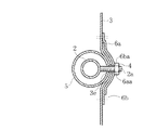
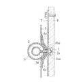
- FIG. 3 is a sectional view taken along line BB in FIG. It is the same figure as FIG. 3 which showed the other Example of the curtain airbag apparatus of this invention.
- the purpose of the present invention is to eliminate the need for a rectifying cloth or a reinforcing cloth, and to deflect a cylinder-shaped inflator and a gas injected from the inflator into the airbag duct in the longitudinal direction of the vehicle in parallel with the duct. Realized by arranging.
- FIGS. 1 is a view showing an embodiment of the curtain airbag device of the present invention in a deployed state
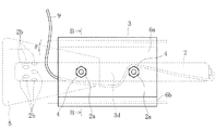
- FIG. 2 is an enlarged view of a portion A in FIG. 1
- FIG. 3 is a cross-sectional view along BB in FIG.
- the pyro-type inflator 2 stores explosives in an elongated cylinder-shaped main body, receives an electrical signal via a harness 9 when the sensor detects a high load from the side of the vehicle body, ignites the explosive, and gas It is the structure which generates.
- the studs 2a are attached in a projecting manner at two locations on the outer peripheral surface of the inflator 2 at a predetermined interval on the same axis.
- the airbag 3 is an airbag that deploys in a curtain shape along the door window W with the gas generated by the inflator 2 as shown in FIG.
- the airbag 3 includes, for example, two chambers 3a and 3b formed in the longitudinal direction of the vehicle, and these chambers 3a and 3b are connected by a straight duct 3c.
- 3f is an attachment piece to the vehicle body 8
- 3g is a tether.
- the airbag 3 is formed in a bag shape and does not have a connection port with the inflator 2, and the inflator 2 is installed inside the duct 3 c of the airbag 3.
- the inflator 2 is installed inside the duct 3 c of the airbag 3 by causing the stud 2 a to protrude through the outer surface side of the airbag 3 and tightening with the nut 4.
- Numeral 5 is a deflector arranged inside the duct 3c.
- the deflector 5 covers the gas injection port 2b of the inflator 2 installed inside the duct 3c, and guides the gas generated by the inflator 2 in the longitudinal direction of the vehicle as parallel as possible to the duct 3c. is there.
- the deflector 5 is made of, for example, a metal so that it will not be damaged even when the gas generated by the inflator 2 is injected.
- the opening area of the opening part of the both ends of the deflector 5 has the internal volume of the chamber 3a located in the vehicle forward side rather than the inflator 2 arrange
- the opening areas of the openings at both ends of the deflector 5 are determined so that both chambers 3a and 3b are developed in the same time.
- the inclination angle ⁇ of the inclined surface of the truncated cone is determined so that the chamber 3a on the vehicle front side and the chamber 3b on the vehicle rear side develop in the same time.
- the height of the truncated cone (length in the vehicle front-rear direction) and the slope surface are set so that the opening area of the truncated cone is proportional to the ratio of the inner volume of the front chamber 3a and the rear chamber 3b. Adjust the tilt angle.
- slits 3d provided with through holes 3e of studs 2a attached to the inflator 2 at both ends are used as the airbag 3.
- the duct 3c is provided.
- the cover member 6a which provided the through-holes 6aa and 6ba of the stud 2a, Cover the slit 3d with 6b and tighten with the nut 4.
- the harness 9 is pulled out from the slit 3d and led out to the outside from the side surfaces of the lid members 6a and 6b covering the slit 3d.
- a bracket 7 may be separately prepared as shown in FIG. If the inflator 2 is fixed to the bracket 7 with the lid members 6a and 6b sandwiched, when the curtain airbag device 1 is attached to the vehicle body 8, it is only necessary to attach the bracket 7 to the vehicle body 8. In addition to improving, it is also possible to reduce gas leakage.
- the deflector 5 is integrated with the inflator 2 by passing through the stud 2a on the side of the inflator 2 close to the gas injection port 2b.
- the gas injected from the gas injection port 2 b of the inflator 2 collides with the inner surface of the deflector 5 and changes direction, and then passes through the duct 3 c from the opening at the front and rear ends of the deflector 5.
- a predetermined amount is introduced into both chambers 3a and 3b.
- the curtain airbag device 1 it is necessary to provide a rectifying cloth that rectifies the flow of gas injected from the gas injection port 2 b of the inflator 2 and a reinforcing cloth that prevents damage to the rectifying cloth inside the airbag 3. Disappears.
- the structure of the airbag 3 is not complicated, and the number of manufacturing steps can be reduced.
- FIGS. 1 to 3 are preferable examples of the present invention, and other embodiments can be implemented or performed by various methods.
- the present invention is not limited to the detailed shape, size, configuration, and the like of the components shown in the accompanying drawings unless otherwise stated in the present specification.
- expressions and terms used in the present specification are for the purpose of explanation, and are not limited thereto unless specifically limited.
- the harness 9 is pulled out from the opposite side of the gas injection port 2b of the slit 3d, and is led out to the outside from the side surface of the lid members 6a, 6b covering the slit 3d on the gas injection port 2b side.
- the drawing-out route of the harness 9 is not limited to the route shown in the above embodiment.
- a pullout hole for the harness 9 may be separately provided in the airbag 3.
- the connection position of the harness 9 to the inflator 2 is not limited to the end face on the opposite side of the gas injection port 2b.
- the inflator to be used is not limited to the pyro type.
- a stored gas type that releases high-pressure gas or a hybrid type inflator that combines both types may be used.
- the deflector 5 is made of metal.
- the deflector 5 is not limited to metal but may be made of resin as long as the shape of the deflector 5 can be maintained without being damaged by being hit by the gas of the inflator 2. It may be made of cloth or cloth used for the base fabric of an airbag.
- the shape of the deflector 5 is not limited to the truncated cone shape as long as the opening area of the openings at both ends of the deflector 5 is a predetermined area.
- the curtain airbag device of the present invention can be installed not only in automobiles but also in side windows of aircraft, ships, etc., and the same effect is exhibited.
Landscapes
- Engineering & Computer Science (AREA)
- Mechanical Engineering (AREA)
- Physics & Mathematics (AREA)
- Fluid Mechanics (AREA)
- Air Bags (AREA)
Abstract
従来必要としていた整流布や補強布を不要とする。 シリンダ状のインフレータ2と、このインフレータ2で発生させたガスによりドアウインドウWに沿って車室内にカーテン状に展開する、複数のチャンバー3a,3bとこれらチャンバー3a,3bを繋ぐダクト3cを有するエアバッグ3と、インフレータ2から噴射するガスを、ダクト3cと平行に車両の前後方向に導出させるディフレクタ4とを備えるカーテンエアバッグ装置1である。インフレータ2及びディフレクタ5を、エアバッグ3のダクト3c内に配置する。
Description
本発明は、例えば車両が側方から衝突された時、乗員の頭部を保護するために、ドアウインドウに沿ってエアバッグをカーテン状に展開させるカーテンエアバッグ装置に関するものである。
カーテンエアバッグ装置は、車体に側部方向から高荷重が作用した時に、インフレータで発生させたガスにより、エアバッグをドアウインドウに沿ってカーテン状に鉛直下向きに展開させるものである。
このカーテン状のエアバッグは、例えばロール状に折り畳まれた状態で自動車のルーフサイドレールに取付けられ、ルーフヘッドライニングに覆われて反車室側に格納される。
そして、展開時には、展開するエアバッグによりルーフヘッドライニングが車室内側に押されてその先端とピラートリムとの係合が外れ、先端側が車室内側に押し広げられてできた開口部からエアバッグが車室内にカーテン状に展開する。
ところで、前記エアバッグのインフレータとの接続部には、エアバッグのダクトに導くガスの流れを整流するための整流布と、この整流布を保護するための補強布が設けられている(例えば特許文献1)。
しかしながら、エアバッグへの整流布の取付けには固定具が必要である。従って、構造が複雑になって製造工数も多くなる。加えて、インフレータが火薬に着火してガスを発生させるパイロ式の場合は、整流布を保護するために多くの補強布が必要になる。
本発明が解決しようとする問題点は、従来のカーテンエアバッグ装置は、エアバッグのインフレータとの接続部に固定具を使用して補強布で保護した整流布を取付ける必要があるため、構造が複雑になって製造工数も多くなるという点である。また、パイロ式インフレータを備えたカーテンエアバッグ装置は、多くの補強布が必要になるという点である。
本発明は、このような観点に基づき、カーテンエアバッグ装置において、整流布や、整流布を保護する補強布を必要としないようにすることを目的とするものである。
すなわち、本発明のカーテンエアバッグ装置は、
シリンダ状のインフレータと、
このインフレータで発生させたガスによりドアウインドウに沿って車室内にカーテン状に展開する、複数のチャンバーとこれらチャンバーを繋ぐダクトを有するエアバッグと、
前記インフレータから噴射するガスを、前記ダクトと平行に車両の前後方向に導出させるディフレクタと、
を備え、
前記インフレータ及び前記ディフレクタを、前記エアバッグのダクト内に配置したことを最も主要な特徴としている。
シリンダ状のインフレータと、
このインフレータで発生させたガスによりドアウインドウに沿って車室内にカーテン状に展開する、複数のチャンバーとこれらチャンバーを繋ぐダクトを有するエアバッグと、
前記インフレータから噴射するガスを、前記ダクトと平行に車両の前後方向に導出させるディフレクタと、
を備え、
前記インフレータ及び前記ディフレクタを、前記エアバッグのダクト内に配置したことを最も主要な特徴としている。
本発明は、エアバッグのダクト内に、シリンダ状のインフレータと、このインフレータから噴射するガスを、前記ダクトと平行に車両の前後方向に導出させるディフレクタを配置するので、従来の整流布や整流布の補強布が不要になる。
本発明は、エアバッグのダクト内に、シリンダ状のインフレータと、このインフレータから噴射するガスを、前記ダクトと平行に車両の前後方向に導出させるディフレクタを配置するので、従来必要としていた整流布や整流布の補強布が不要になる。
本発明は、整流布や補強布を不要とするという目的を、エアバッグのダクト内に、シリンダ状のインフレータと、インフレータから噴射するガスを、前記ダクトと平行に車両の前後方向に導出させるディフレクタを配置することで実現した。
以下、本発明のカーテンエアバッグ装置の実施例を図1~図4を用いて説明する。
図1は展開状態の本発明のカーテンエアバッグ装置の一実施例を示した図、図2は図1のA部拡大図、図3は図2のB-B断面図である。
図1は展開状態の本発明のカーテンエアバッグ装置の一実施例を示した図、図2は図1のA部拡大図、図3は図2のB-B断面図である。
1はカーテンエアバッグ装置であり、例えばパイロ式インフレータ2を使用している。パイロ式インフレータ2は、細長いシリンダ状の本体の内部に火薬を収納し、センサーが車体側方からの高荷重を検出したときにハーネス9を介して電気信号を受け、前記火薬に着火してガスを発生させる構成である。本発明では、このインフレータ2の外周面の、同一軸線上の所定間隔を隔てた2か所に、スタッド2aを突出状に取付けている。
3は、インフレータ2で発生させたガスにより、図1に示すように、ドアウインドウWに沿って車室内をカーテン状に展開するエアバッグである。このエアバッグ3は、例えば、車両の前後方向に2個のチャンバー3a,3bを形成し、これらチャンバー3a,3bをストレートなダクト3cで繋いでいる。なお、3fは車体8への取付片、3gはテザーである。
すなわち、本発明では、エアバッグ3は袋状に形成されてインフレータ2との接続口を有しておらず、インフレータ2はエアバッグ3のダクト3cの内部に設置する。エアバッグ3のダクト3cの内部への前記インフレータ2の設置は、前記スタッド2aをエアバッグ3の外面側に貫通して突出させ、ナット4で締付けることによって行う。
5は、前記ダクト3cの内部に配置するディフレクタである。このディフレクタ5は、前記ダクト3cの内部に設置したインフレータ2のガス噴射口2bを覆い、かつ、前記インフレータ2で発生したガスを、できるだけ前記ダクト3cと平行に、車両の前後方向に導くものである。
このディフレクタ5は、インフレータ2で発生したガスの噴射を受けても損傷しないように、例えば金属製のものが採用される。
また、ディフレクタ5の両端の開口部の開口面積は、ダクト3cの内部に配置されたインフレータ2よりも車両前方側に位置するチャンバー3aの内容積と、インフレータ2よりも車両後方側に位置するチャンバー3bの内容積に応じて決定する。
例えば、両チャンバー3a,3bが同じ時間で展開するように、ディフレクタ5の両端の開口部の開口面積を決定する。この場合、図1~図3に示す円錐台形状のディフレクタ5では、車両前方側のチャンバー3aと車両後方側のチャンバー3bが同じ時間で展開するように、円錐台の斜面の傾斜角度θを決定する。具体的には、円錐台の開口面積が前方側のチャンバー3aと後方側のチャンバー3bの内容積の比に比例するように、円錐台の高さ(車両前後方向の長さ)と、斜面の傾斜角度を調整する。
本実施例では、エアバッグ3のダクト3cの内部にインフレータ2及びディフレクタ5を設置する手段として、前記インフレータ2に取付けたスタッド2aの貫通孔3eを両端部に設けたスリット3dを、エアバッグ3のダクト3c部に設けている。
そして、インフレータ2及びディフレクタ5を一体としたガス発生部を前記スリット3dから挿入した後は、エアバッグ3の展開状態における上下方向から、スタッド2aの貫通孔6aa,6baを設けた蓋部材6a,6bでスリット3dを覆いナット4で締付ける。このとき、例えばスリット3dからハーネス9を引出し、スリット3dを覆う蓋部材6a,6bの側面側から外部に導出する。このようにすることで、スリット3dからインフレータ2のガスが漏れないようになる。
前記ガス発生部をエアバッグ3のダクト3cの内部にナット4で締付ける際に、図4に示すように、ブラケット7を別途用意してもよい。ブラケット7に蓋部材6a,6bを挟んでインフレータ2を固定すれば、カーテンエアバッグ装置1を車体8に取り付ける際には、ブラケット7を車体8に取り付けるだけで良いので、取り付け時の作業性が向上するほか、ガス漏れを少なくすることも可能となる。
図1,2の実施例では、ディフレクタ5は、インフレータ2のガス噴射口2bに近い側のスタッド2aを貫通させることで、インフレータ2と一体となしている。
上記カーテンエアバッグ装置1の場合、インフレータ2のガス噴射口2bから噴射されたガスは、ディフレクタ5の内面に衝突して方向転換した後、ディフレクタ5の前後端の開口部からダクト3cを通って両チャンバー3a,3bに所定量ずつ導入される。
その際、ダクト3cがストレートであれば、両チャンバー3a,3bに導かれたガスがダクト3cに衝突してダクト3cを損傷させることを抑制できる。
つまり、上記カーテンエアバッグ装置1では、インフレータ2のガス噴射口2bから噴射されたガスの流れを整流する整流布や、この整流布の損傷を防ぐ補強布を、エアバッグ3の内部に設ける必要がなくなる。
また、整流布をエアバッグ3の内部に取付けるための固定具も必要としないので、エアバッグ3の構造が複雑にならず、製造工数も少なくて済む。
本発明は上記の例に限らず、各請求項に記載された技術的思想の範疇に含まれるものであれば、適宜実施の形態を変更しても良いことは言うまでもない。
すなわち、図1~図3で説明した実施例は、本発明の好ましい例であって、これ以外の実施態様も、各種の方法で実施または遂行できる。特に、本願明細書中に限定する主旨の記載がない限り、本発明は添付図面に示した詳細な部品の形状、大きさ、および構成配置等に制約されるものではない。また、本願明細書の中に用いられた表現および用語は、説明を目的としたもので、特に限定される主旨のない限り、それに限定されるものではない。
例えば、上記の実施例では、スリット3dのガス噴射口2bの反対側からハーネス9を引出し、スリット3dを覆う蓋部材6a,6bのガス噴射口2b側の側面から外部に導出している。しかしながら、ハーネス9の引出し経路は上記実施例で示した経路に限らない。また、エアバッグ3からハーネス9を引出すために、エアバッグ3にハーネス9の引出し用孔を別途設けてもよい。また、インフレータ2へのハーネス9の接続位置も、ガス噴射口2bの反対側の端面に限らない。
また、上記の実施例では、パイロ式のインフレータ2を使用したものについて説明したが、使用するインフレータはパイロ式に限らない。高圧ガスを放出させるストアードガス方式や、両方式を組み合わせたハイブリッド方式のインフレータでも良い。
また、上記の実施例では、ディフレクタ5は金属製のものを示したが、インフレータ2のガスが当たることによって損傷せず、かつ、形状を維持できるものであれば、金属製に限らず、樹脂製のものやエアバッグの基布に用いるような布製のものでも良い。ディフレクタ5の形状も、ディフレクタ5の両端の開口部の開口面積が所定の面積となれば円錐台形状に限らない。
本発明のカーテンエアバッグ装置は、自動車だけでなく航空機や船舶等のサイドウィンドウ部に設置することも可能であり、同様な効果が発揮される。
1 カーテンエアバッグ装置
2 インフレータ
2a スタッド
3 エアバッグ
3a,3b チャンバー
3c ダクト
3d スリット
5 ディフレクタ
6a,6b 蓋部材
9 ハーネス
W ドアウインドウ
2 インフレータ
2a スタッド
3 エアバッグ
3a,3b チャンバー
3c ダクト
3d スリット
5 ディフレクタ
6a,6b 蓋部材
9 ハーネス
W ドアウインドウ
Claims (13)
- シリンダ状のインフレータと、
このインフレータで発生させたガスによりドアウインドウに沿って車室内にカーテン状に展開する、複数のチャンバーとこれらチャンバーを繋ぐダクトを有するエアバッグと、
前記インフレータから噴射するガスを、前記ダクトと平行に車両の前後方向に導出させるディフレクタと、
を備え、
前記インフレータ及び前記ディフレクタを、前記エアバッグのダクト内に配置したことを特徴とするカーテンエアバッグ装置。 - 前記エアバッグのダクト部に、前記インフレータ及び前記ディフレクタを一体としたガス発生部を挿入可能なスリットを設けたことを特徴とする請求の範囲第1項に記載のカーテンエアバッグ装置。
- 前記スリットを覆う蓋部材を前記エアバッグの外側に設けたことを特徴とする請求の範囲第2項に記載のカーテンエアバッグ装置。
- 前記インフレータは、電気信号を受けるためのハーネスを有し、当該ハーネスは前記スリットを通って外部に導出されることを特徴とする請求の範囲第2項又は第3項に記載のカーテンエアバッグ装置。
- 前記ディフレクタは、長手方向両端の開口部の開口面積が異なっていることを特徴とする請求の範囲第1項~第3項の何れかに記載のカーテンエアバッグ装置。
- 前記ディフレクタは、長手方向両端の開口部の開口面積が異なっていることを特徴とする請求の範囲第4項に記載のカーテンエアバッグ装置。
- 前記ディフレクタの前記両端の開口部の開口面積は、ダクト内に配置された前記インフレータの車両前方側に位置するチャンバーの内容積と前記インフレータの車両後方側に位置するチャンバーの内容積に比例して決定されることを特徴とする請求の範囲第1項~第3項、第6項の何れかに記載のカーテンエアバッグ装置。
- 前記ディフレクタの前記両端の開口部の開口面積は、ダクト内に配置された前記インフレータの車両前方側に位置するチャンバーの内容積と前記インフレータの車両後方側に位置するチャンバーの内容積に比例して決定されることを特徴とする請求の範囲第4項に記載のカーテンエアバッグ装置。
- 前記ディフレクタの前記両端の開口部の開口面積は、ダクト内に配置された前記インフレータの車両前方側に位置するチャンバーの内容積と前記インフレータの車両後方側に位置するチャンバーの内容積に比例して決定されることを特徴とする請求の範囲第5項に記載のカーテンエアバッグ装置。
- 前記インフレータ及び前記ディフレクタの前記エアバッグへの取付けは、前記インフレータの外周部に突出状に設けたスタッドを使用して行うことを特徴とする請求の範囲第1項~第3項、第6項、第8項、第9項の何れかに記載のカーテンエアバッグ装置。
- 前記インフレータ及び前記ディフレクタの前記エアバッグへの取付けは、前記インフレータの外周部に突出状に設けたスタッドを使用して行うことを特徴とする請求の範囲第4項に記載のカーテンエアバッグ装置。
- 前記インフレータ及び前記ディフレクタの前記エアバッグへの取付けは、前記インフレータの外周部に突出状に設けたスタッドを使用して行うことを特徴とする請求の範囲第5項に記載のカーテンエアバッグ装置。
- 前記インフレータ及び前記ディフレクタの前記エアバッグへの取付けは、前記インフレータの外周部に突出状に設けたスタッドを使用して行うことを特徴とする請求の範囲第7項に記載のカーテンエアバッグ装置。
Priority Applications (1)
| Application Number | Priority Date | Filing Date | Title |
|---|---|---|---|
| JP2015554748A JP6228992B2 (ja) | 2013-12-26 | 2014-12-15 | カーテンエアバッグ装置 |
Applications Claiming Priority (2)
| Application Number | Priority Date | Filing Date | Title |
|---|---|---|---|
| JP2013-269761 | 2013-12-26 | ||
| JP2013269761 | 2013-12-26 |
Publications (1)
| Publication Number | Publication Date |
|---|---|
| WO2015098587A1 true WO2015098587A1 (ja) | 2015-07-02 |
Family
ID=53478451
Family Applications (1)
| Application Number | Title | Priority Date | Filing Date |
|---|---|---|---|
| PCT/JP2014/083078 Ceased WO2015098587A1 (ja) | 2013-12-26 | 2014-12-15 | カーテンエアバッグ装置 |
Country Status (2)
| Country | Link |
|---|---|
| JP (1) | JP6228992B2 (ja) |
| WO (1) | WO2015098587A1 (ja) |
Citations (6)
| Publication number | Priority date | Publication date | Assignee | Title |
|---|---|---|---|---|
| JPH09169253A (ja) * | 1995-12-20 | 1997-06-30 | Nippon Seiko Kk | エアバッグ装置 |
| JP2000296751A (ja) * | 1999-04-15 | 2000-10-24 | Honda Motor Co Ltd | 乗員拘束装置 |
| US20030141708A1 (en) * | 2002-01-30 | 2003-07-31 | Enders Mark L. | Pressure equalizing curtain airbag |
| WO2009093389A1 (ja) * | 2008-01-24 | 2009-07-30 | Autoliv Development Ab | 頭部保護用エアバッグ装置 |
| JP2010006333A (ja) * | 2008-06-30 | 2010-01-14 | Nippon Plast Co Ltd | エアバッグ装置 |
| JP2011168167A (ja) * | 2010-02-18 | 2011-09-01 | Takata Corp | エアバッグ及びエアバッグ装置 |
-
2014
- 2014-12-15 WO PCT/JP2014/083078 patent/WO2015098587A1/ja not_active Ceased
- 2014-12-15 JP JP2015554748A patent/JP6228992B2/ja active Active
Patent Citations (6)
| Publication number | Priority date | Publication date | Assignee | Title |
|---|---|---|---|---|
| JPH09169253A (ja) * | 1995-12-20 | 1997-06-30 | Nippon Seiko Kk | エアバッグ装置 |
| JP2000296751A (ja) * | 1999-04-15 | 2000-10-24 | Honda Motor Co Ltd | 乗員拘束装置 |
| US20030141708A1 (en) * | 2002-01-30 | 2003-07-31 | Enders Mark L. | Pressure equalizing curtain airbag |
| WO2009093389A1 (ja) * | 2008-01-24 | 2009-07-30 | Autoliv Development Ab | 頭部保護用エアバッグ装置 |
| JP2010006333A (ja) * | 2008-06-30 | 2010-01-14 | Nippon Plast Co Ltd | エアバッグ装置 |
| JP2011168167A (ja) * | 2010-02-18 | 2011-09-01 | Takata Corp | エアバッグ及びエアバッグ装置 |
Also Published As
| Publication number | Publication date |
|---|---|
| JP6228992B2 (ja) | 2017-11-08 |
| JPWO2015098587A1 (ja) | 2017-03-23 |
Similar Documents
| Publication | Publication Date | Title |
|---|---|---|
| CN108463378B (zh) | 帘式气囊装置及其对车辆的安装结构 | |
| WO2010016398A1 (ja) | 車両用ニーエアバッグ装置 | |
| US20090091105A1 (en) | Air bag system for vehicle | |
| KR20090032577A (ko) | 사이드 커튼 에어백 유닛 | |
| US8430423B2 (en) | Interior structure of vehicle | |
| JP2015134564A (ja) | 歩行者用エアバッグ装置及び自動車 | |
| JP5988611B2 (ja) | エアバッグ装置 | |
| JP5968292B2 (ja) | 車両用エアバッグのガスガイドおよびエアバッグ装置 | |
| JP2010235043A (ja) | エアバッグ装置 | |
| JP5046830B2 (ja) | エアバッグ装置 | |
| JP5550315B2 (ja) | エアバッグ装置 | |
| JP5435913B2 (ja) | エアバッグ装置 | |
| JP6228992B2 (ja) | カーテンエアバッグ装置 | |
| JP2011218994A (ja) | 車両用カーテンエアバッグ装置 | |
| JP2010083240A (ja) | エアバッグ及びエアバッグ装置 | |
| US10336281B2 (en) | Airbag apparatus | |
| JP2014159277A (ja) | カーテンエアバッグ装置 | |
| KR20190035109A (ko) | 커튼 에어백 장치 | |
| JP5992855B2 (ja) | カーテンエアバッグ装置及びその取付け構造 | |
| JP2009078717A (ja) | エアバッグ装置 | |
| KR20170008385A (ko) | 무릎 에어백 장치 | |
| JP5964798B2 (ja) | カーテンエアバッグ装置 | |
| JP5414089B2 (ja) | エアバッグ装置 | |
| JP5005408B2 (ja) | エアバッグ装置 | |
| JP2016120873A (ja) | 自動車用カーテンエアバッグの展開構造 |
Legal Events
| Date | Code | Title | Description |
|---|---|---|---|
| 121 | Ep: the epo has been informed by wipo that ep was designated in this application |
Ref document number: 14875853 Country of ref document: EP Kind code of ref document: A1 |
|
| ENP | Entry into the national phase |
Ref document number: 2015554748 Country of ref document: JP Kind code of ref document: A |
|
| NENP | Non-entry into the national phase |
Ref country code: DE |
|
| 122 | Ep: pct application non-entry in european phase |
Ref document number: 14875853 Country of ref document: EP Kind code of ref document: A1 |