WO2015098523A1 - 地絡検出装置 - Google Patents
地絡検出装置 Download PDFInfo
- Publication number
- WO2015098523A1 WO2015098523A1 PCT/JP2014/082702 JP2014082702W WO2015098523A1 WO 2015098523 A1 WO2015098523 A1 WO 2015098523A1 JP 2014082702 W JP2014082702 W JP 2014082702W WO 2015098523 A1 WO2015098523 A1 WO 2015098523A1
- Authority
- WO
- WIPO (PCT)
- Prior art keywords
- voltage value
- ground fault
- solar cell
- acquisition unit
- fault detection
- Prior art date
- Legal status (The legal status is an assumption and is not a legal conclusion. Google has not performed a legal analysis and makes no representation as to the accuracy of the status listed.)
- Ceased
Links
Images

Classifications
-
- H—ELECTRICITY
- H02—GENERATION; CONVERSION OR DISTRIBUTION OF ELECTRIC POWER
- H02S—GENERATION OF ELECTRIC POWER BY CONVERSION OF INFRARED RADIATION, VISIBLE LIGHT OR ULTRAVIOLET LIGHT, e.g. USING PHOTOVOLTAIC [PV] MODULES
- H02S50/00—Monitoring or testing of PV systems, e.g. load balancing or fault identification
- H02S50/10—Testing of PV devices, e.g. of PV modules or single PV cells
-
- G—PHYSICS
- G01—MEASURING; TESTING
- G01R—MEASURING ELECTRIC VARIABLES; MEASURING MAGNETIC VARIABLES
- G01R31/00—Arrangements for testing electric properties; Arrangements for locating electric faults; Arrangements for electrical testing characterised by what is being tested not provided for elsewhere
- G01R31/50—Testing of electric apparatus, lines, cables or components for short-circuits, continuity, leakage current or incorrect line connections
- G01R31/52—Testing for short-circuits, leakage current or ground faults
-
- H—ELECTRICITY
- H02—GENERATION; CONVERSION OR DISTRIBUTION OF ELECTRIC POWER
- H02H—EMERGENCY PROTECTIVE CIRCUIT ARRANGEMENTS
- H02H3/00—Emergency protective circuit arrangements for automatic disconnection directly responsive to an undesired change from normal electric working condition with or without subsequent reconnection ; integrated protection
- H02H3/16—Emergency protective circuit arrangements for automatic disconnection directly responsive to an undesired change from normal electric working condition with or without subsequent reconnection ; integrated protection responsive to fault current to earth, frame or mass
-
- H—ELECTRICITY
- H02—GENERATION; CONVERSION OR DISTRIBUTION OF ELECTRIC POWER
- H02H—EMERGENCY PROTECTIVE CIRCUIT ARRANGEMENTS
- H02H7/00—Emergency protective circuit arrangements specially adapted for specific types of electric machines or apparatus or for sectionalised protection of cable or line systems, and effecting automatic switching in the event of an undesired change from normal working conditions
- H02H7/10—Emergency protective circuit arrangements specially adapted for specific types of electric machines or apparatus or for sectionalised protection of cable or line systems, and effecting automatic switching in the event of an undesired change from normal working conditions for converters; for rectifiers
- H02H7/12—Emergency protective circuit arrangements specially adapted for specific types of electric machines or apparatus or for sectionalised protection of cable or line systems, and effecting automatic switching in the event of an undesired change from normal working conditions for converters; for rectifiers for static converters or rectifiers
- H02H7/122—Emergency protective circuit arrangements specially adapted for specific types of electric machines or apparatus or for sectionalised protection of cable or line systems, and effecting automatic switching in the event of an undesired change from normal working conditions for converters; for rectifiers for static converters or rectifiers for inverters, i.e. DC/AC converters
- H02H7/1222—Emergency protective circuit arrangements specially adapted for specific types of electric machines or apparatus or for sectionalised protection of cable or line systems, and effecting automatic switching in the event of an undesired change from normal working conditions for converters; for rectifiers for static converters or rectifiers for inverters, i.e. DC/AC converters responsive to abnormalities in the input circuit, e.g. transients in the DC input
-
- H—ELECTRICITY
- H02—GENERATION; CONVERSION OR DISTRIBUTION OF ELECTRIC POWER
- H02S—GENERATION OF ELECTRIC POWER BY CONVERSION OF INFRARED RADIATION, VISIBLE LIGHT OR ULTRAVIOLET LIGHT, e.g. USING PHOTOVOLTAIC [PV] MODULES
- H02S50/00—Monitoring or testing of PV systems, e.g. load balancing or fault identification
-
- H—ELECTRICITY
- H02—GENERATION; CONVERSION OR DISTRIBUTION OF ELECTRIC POWER
- H02S—GENERATION OF ELECTRIC POWER BY CONVERSION OF INFRARED RADIATION, VISIBLE LIGHT OR ULTRAVIOLET LIGHT, e.g. USING PHOTOVOLTAIC [PV] MODULES
- H02S40/00—Components or accessories in combination with PV modules, not provided for in groups H02S10/00 - H02S30/00
- H02S40/30—Electrical components
- H02S40/32—Electrical components comprising DC/AC inverter means associated with the PV module itself, e.g. AC modules
-
- H—ELECTRICITY
- H02—GENERATION; CONVERSION OR DISTRIBUTION OF ELECTRIC POWER
- H02S—GENERATION OF ELECTRIC POWER BY CONVERSION OF INFRARED RADIATION, VISIBLE LIGHT OR ULTRAVIOLET LIGHT, e.g. USING PHOTOVOLTAIC [PV] MODULES
- H02S40/00—Components or accessories in combination with PV modules, not provided for in groups H02S10/00 - H02S30/00
- H02S40/30—Electrical components
- H02S40/38—Energy storage means, e.g. batteries, structurally associated with PV modules
-
- Y—GENERAL TAGGING OF NEW TECHNOLOGICAL DEVELOPMENTS; GENERAL TAGGING OF CROSS-SECTIONAL TECHNOLOGIES SPANNING OVER SEVERAL SECTIONS OF THE IPC; TECHNICAL SUBJECTS COVERED BY FORMER USPC CROSS-REFERENCE ART COLLECTIONS [XRACs] AND DIGESTS
- Y02—TECHNOLOGIES OR APPLICATIONS FOR MITIGATION OR ADAPTATION AGAINST CLIMATE CHANGE
- Y02E—REDUCTION OF GREENHOUSE GAS [GHG] EMISSIONS, RELATED TO ENERGY GENERATION, TRANSMISSION OR DISTRIBUTION
- Y02E10/00—Energy generation through renewable energy sources
- Y02E10/50—Photovoltaic [PV] energy
-
- Y—GENERAL TAGGING OF NEW TECHNOLOGICAL DEVELOPMENTS; GENERAL TAGGING OF CROSS-SECTIONAL TECHNOLOGIES SPANNING OVER SEVERAL SECTIONS OF THE IPC; TECHNICAL SUBJECTS COVERED BY FORMER USPC CROSS-REFERENCE ART COLLECTIONS [XRACs] AND DIGESTS
- Y02—TECHNOLOGIES OR APPLICATIONS FOR MITIGATION OR ADAPTATION AGAINST CLIMATE CHANGE
- Y02E—REDUCTION OF GREENHOUSE GAS [GHG] EMISSIONS, RELATED TO ENERGY GENERATION, TRANSMISSION OR DISTRIBUTION
- Y02E70/00—Other energy conversion or management systems reducing GHG emissions
- Y02E70/30—Systems combining energy storage with energy generation of non-fossil origin
Definitions
- the present invention relates to a ground fault detection device and a program.
- Patent Document 1 discloses a method for detecting a ground fault of a solar cell string in a state in which the solar cell string and the power conditioner are electrically separated by a switch unit provided between the solar cell string and the power conditioner. A fault detector is disclosed.
- the ground fault detection device detects a ground fault of the solar cell string while the power conditioner is operating, a large current may flow from the solar cell string to the switch unit. Therefore, parts that can withstand large currents were used.
- the power conversion device is stopped by the stop determination unit that determines whether or not the power conversion device that converts the power from the solar cell is stopped, and the stop determination unit. If the solar cell and the power conversion device are electrically disconnected by a cutting means provided between the solar cell and the power conversion device, the ground for detecting the ground fault of the solar cell is determined.
- a tangle detector A tangle detector.
- the ground fault detection device further includes a voltage value acquisition unit that acquires a voltage value of a voltage output from the solar cell, and the ground fault detection unit has a voltage value acquired by the voltage value acquisition unit as a first reference voltage value. If it is larger, a ground fault of the solar cell may be detected.
- the stop determination unit may determine that the power conversion device is stopped when the voltage value acquired by the voltage value acquisition unit is smaller than the second reference voltage value.
- the stop determination unit is configured to convert the power conversion device when the voltage value acquired by the voltage value acquisition unit is smaller than the second reference voltage value and the current timing is included in a predetermined period. May be determined to be stopped.
- the stop determination unit may determine that the power conversion device is stopped when the change in the voltage value acquired by the voltage value acquisition unit satisfies a predetermined condition.
- the stop determination unit performs power conversion when a change in the voltage value acquired by the voltage value acquisition unit satisfies a predetermined condition and the current timing is included in a predetermined period. It may be determined that the device is stopped.
- the ground fault detection device further includes a current value acquisition unit that acquires a current value of a current output from the solar cell, and the stop determination unit is configured such that the voltage value acquired by the voltage value acquisition unit is a second reference voltage value. If the current value acquired by the current value acquisition unit is smaller than the reference current value, it may be determined that the power converter is stopped.
- the stop determination unit is configured such that the voltage value acquired by the voltage value acquisition unit is smaller than the second reference voltage value, and the current value acquired by the current value acquisition unit is smaller than the reference current value. And when the present timing is contained in the predetermined period, you may determine with the power converter device having stopped.
- the ground fault detection device further includes a solar radiation amount acquisition unit that acquires a solar radiation amount, and the stop determination unit stops the power conversion device when the solar radiation amount acquired by the solar radiation amount acquisition unit satisfies a predetermined condition. You may determine that you are doing.
- the stop determination unit is configured such that the solar radiation amount acquired by the solar radiation amount acquisition unit satisfies a predetermined condition and the voltage value acquired by the voltage value acquisition unit is greater than the second reference voltage value. When it is small, it may be determined that the power converter is stopped.
- the stop determination unit satisfies a condition in which the amount of solar radiation acquired by the solar radiation amount acquisition unit satisfies a predetermined condition, and a condition in which a change in the voltage value acquired by the voltage value acquisition unit is predetermined.
- filling you may determine with the power converter device having stopped.
- the ground fault detection device further includes a current value acquisition unit that acquires a current value of a current output from the solar cell, and the stop determination unit has a condition that the amount of solar radiation acquired by the solar radiation amount acquisition unit is predetermined. If the voltage value acquired by the voltage value acquisition unit is smaller than the second reference voltage value and the current value acquired by the current value acquisition unit is smaller than the reference current value, the power converter is stopped. May be determined.
- the voltage value acquisition unit that acquires the voltage value of the voltage output from the solar cell, and the voltage value acquired by the voltage value acquisition unit are based on the first reference voltage value. If the voltage value is greater than the second reference voltage value, or if the voltage value is greater than the first reference voltage value and the change in the voltage value satisfies a predetermined condition, the power from the solar cell and the solar cell is reduced.
- a ground fault detection unit that detects a ground fault of the solar cell in a state in which the solar cell and the power conversion device are electrically disconnected by a cutting means provided between the power converter to be converted.
- the ground fault detection unit is configured such that the voltage value acquired by the voltage value acquisition unit is larger than the first reference voltage value and smaller than the second reference voltage value, and the current timing is predetermined.
- the cutting means When included in the period, or when the voltage value is larger than the first reference voltage value and the change in the voltage value satisfies a predetermined condition and the current timing is included in the predetermined period, the cutting means The ground fault of the solar cell may be detected in a state in which the solar cell and the power conversion device are electrically disconnected.
- a ground fault detection device includes a voltage value acquisition unit that acquires a voltage value of a voltage output from a solar cell, and a current value acquisition unit that acquires a current value of a current output from the solar cell.
- a voltage value acquisition unit that acquires a voltage value of a voltage output from a solar cell
- a current value acquisition unit that acquires a current value of a current output from the solar cell.
- the ground fault detection apparatus includes a solar radiation amount acquisition unit that acquires the solar radiation amount, and a solar battery and a solar battery when the solar radiation amount acquired by the solar radiation amount acquisition unit satisfies a predetermined condition.
- a ground fault detector for detecting a ground fault of the solar cell in a state in which the solar cell and the power converter are electrically disconnected by a cutting means provided between the power converter and the power converter .
- the ground fault detection device further includes a voltage value acquisition unit that acquires a voltage value of a current output from the solar cell, and the ground fault detection unit is a condition in which the amount of solar radiation acquired by the solar radiation amount acquisition unit is predetermined. And the voltage value acquired by the voltage value acquisition unit is larger than the first reference voltage value and smaller than the second reference voltage value, or the amount of solar radiation satisfies a predetermined condition and the voltage value is When the voltage value is larger than the first reference voltage value and the change in the voltage value satisfies a predetermined condition, a ground fault of the solar cell is detected in a state where the solar cell and the power conversion device are electrically disconnected by the cutting means. May be.
- the cutting means may be a relay having a b contact.
- the ground fault detection device may further include a power supply unit that supplies power from the solar battery to the ground fault detection device.
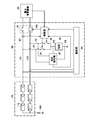
- FIG. 1 It is a figure which shows an example of the whole structure of the solar energy power generation system containing the ground fault detection apparatus which concerns on this embodiment. It is a figure which shows an example of the functional block of a control part. It is a figure which shows an example of the mode of the change in the morning of the voltage input into a power converter device. It is a figure which shows an example of the mode of the change in the evening of the voltage input into a power converter device. It is a figure which shows an example of the flowchart in case a ground fault detection apparatus performs the process which detects the ground fault of a solar cell in the morning. It is a figure which shows an example of the flowchart in case a ground fault detection apparatus performs the process which detects the ground fault of a solar cell in the evening.
- FIG. 1 shows an example of the overall configuration of a photovoltaic power generation system including a ground fault detection device 30 according to the present embodiment.
- the solar power generation system includes a solar battery 10, a power converter 20, and a ground fault detector 30.
- the solar cell 10 may be a solar cell string having a plurality of solar cell modules 12 connected in series.
- the solar cell 10 may be a single solar cell, a solar cell module in which solar cells are connected in series or in parallel, and the like.
- the power converter 20 converts the power output from the solar cell 10.
- the power converter 20 may be a power conditioner that boosts the direct current from the solar cell 10, converts the boosted direct current to alternating current, and links the system power supply.
- the ground fault detection device 30 derives an insulation resistance value between the solar cell 10 and the grounding point, and determines that a ground fault has occurred when the derived insulation resistance value is smaller than the reference resistance value.
- the ground fault detection device 30 includes a cutting unit 32, a switch 34, a switch 36, a resistor 38, a voltage detection unit 40, a current sensor 42, a power supply unit 44, and a control unit 100.
- the cutting means 32 is provided between the solar cell 10 and the power conversion device 20, and electrically disconnects the solar cell 10 and the power conversion device 20.
- the cutting means 32 includes a relay provided between the output terminal on the high potential side of the solar cell 10 and the input terminal on the high potential side of the power converter 20, the output terminal on the low potential side of the solar cell 10, And a relay provided between the low-potential side input terminal of the converter 20.
- Each relay may be a relay having a b-contact that electrically disconnects the solar cell 10 and the power conversion device 20 when an operation signal is input.
- the high potential side relay of the cutting means 32 and the high potential side output terminal of the solar cell 10 are connected via a high potential side electric wire L1.
- the low potential side relay of the cutting means 32 and the low potential side output terminal of the solar cell 10 are connected via a low potential side electric wire L2.
- One end of the switch 34 is connected to the electric wire L1 on the high potential side, and the other end of the switch 34 is connected to one end of the resistor 38.
- One end of the switch 36 is connected to the electric wire L ⁇ b> 2 on the low potential side, and the other end of the switch 36 is connected to one end of the resistor 38. The other end of the resistor 38 is grounded.
- the voltage detection unit 40 is between the point P3 on the wire connecting the switch 34 and one end of the resistor 38 and the point P4 on the other end side of the resistor 38.
- the voltage V1 is detected.
- the voltage detection unit 40 detects the voltage V2 between the point P3 and the point P4 with the switch 34 turned off and the switch 36 turned on.
- the voltage detection unit 40 is connected to the point P1 on the electric wire connecting the electric wire L1 and one end of the switch 34, and the electric wire connecting the electric wire L2 and one end of the switch 36 with the switch 34 turned off and the switch 36 turned off.
- a voltage V0 between the current point P2 and the current point P2 is detected.
- the voltage V0 corresponds to the voltage across the solar cell 10.
- the current sensor 42 detects the current value I0 of the current output from the solar cell 10.
- the control unit 100 controls the relay operation of the cutting unit 32.
- the control unit 100 controls the switching operation of the switch 34 and the switch 36. Further, the control unit 100 derives the resistance value R0 of the insulation resistance 200 of the solar cell 10 based on the voltage V1, the voltage V2, and the voltage V0 detected by the voltage detection unit 40, and based on the resistance value R0, The presence or absence of a ground fault of the battery 10 is detected.
- the resistance value of the resistor 38 is R1
- the electromotive force of the solar cell 10 is E
- the current output from the solar cell 10 is I
- the resistance value of the solar cell 10 is Rpv
- the switch 34 is on
- the switch 36 is off.
- Equation (1) can be derived from Ohm's law.
- Rpv Va / V1 ⁇ R1 (1)
- Rpv Va / V1 ⁇ R1
- R0 Va / V1 ⁇ R1-R1
- the resistance value of the resistor 38 is R1
- the electromotive force of the solar cell 10 is E
- the current output from the solar cell 10 is I
- the resistance value of the solar cell 10 is Rpv
- the switch 34 is off
- the switch 36 is on.
- the resistance value R0 can be derived from Equation (2), Equation (4), and
- V0, from Equation (5).
- R0 R1 ⁇
- ⁇ R1 R1 ⁇ V0 /
- control unit 100 can derive the resistance value R0 according to the equation (5). Note that when detecting the potential Va or the potential Vb, the control unit 100 may derive the resistance value R0 according to the equation (2) or the equation (4).
- Control unit 100 determines that there is no ground fault of solar cell 10 if resistance value R0 is equal to or greater than a predetermined reference resistance value Rt. If resistance value R0 is less than reference resistance value Rt, control unit 100 determines that solar cell 10 has a ground fault.
- the power supply unit 44 supplies the power supplied from the solar cell 10 to the control unit 100.
- the ground fault detection device 30 configured as described above electrically disconnects the solar cell 10 and the power conversion device 20 by the cutting means 32, A ground fault of the solar cell 10 is detected.
- the ground fault detection device 30 has a voltage value Vin of a voltage output from the solar cell 10 and input to the power conversion device 20 greater than a predetermined first reference voltage value Vt1 and a predetermined second reference voltage.
- Vt2 higher reference voltage
- the first reference voltage value Vt1 may be a value equal to or greater than the minimum voltage value at which the ground fault detection device 30 can detect the ground fault of the solar cell 10 without being affected by noise.
- the second reference voltage value Vt2 may be a value equal to or less than the maximum voltage value at which the power conversion device 20 cannot output the required power. When a voltage greater than the second reference voltage value Vt2 is input from the solar cell 10, the power conversion device 20 converts the direct current input from the solar cell 10 into an alternating current of the requested voltage and outputs the alternating current.
- the ground fault detection device 30 is disconnected by the cutting means 32 while the power conversion device 20 is stopped.
- the ground fault of the solar cell 10 may be detected by electrically blocking between the solar cell 10 and the power conversion device 20.
- the ground fault detection device 30 When the voltage value Vin of the voltage output from the solar cell 10 and input to the power conversion device 20 is greater than the first reference voltage value Vt1 that is determined in advance, the ground fault detection device 30 further determines the voltage value Vin in advance. If the current reference voltage value Vt2 (> Vt1) is smaller than the reference current value It and the current I0 output from the solar cell 10 is smaller than the reference current value It, there is a high possibility that the power converter 20 has stopped. The fault detection device 30 detects a ground fault of the solar cell 10 by electrically disconnecting the solar cell 10 and the power conversion device 20 by the cutting means 32 while the power conversion device 20 is stopped. It's okay.
- the cutting means 32 can be operated only when the current flowing through the cutting means 32 is small. By limiting the timing at which the cutting means 32 operates when the current flowing through the cutting means 32 is small, the cutting means 32 is not operated when the current flowing through the cutting means 32 is large. Therefore, assuming that the current flowing through the cutting means 32 becomes large, it is not necessary to select a part that can withstand a large current as a part constituting the cutting means 32. Furthermore, it is not necessary to select an expensive component that can withstand a large current as a relay constituting the cutting means 32. Moreover, the relay which comprises the cutting
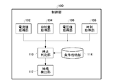
- FIG. 2 is a diagram illustrating an example of functional blocks of the control unit 100.
- the control unit 100 includes a current value acquisition unit 102, a solar radiation amount acquisition unit 104, a voltage value acquisition unit 106, a time acquisition unit 108, a stop determination unit 110, a ground fault detection unit 112, and a condition storage unit 114.
- Each unit included in the control unit 100 is stored in a computer-readable recording medium, and can be configured by installing a program for performing various processes related to detection of a ground fault of the solar battery 10 and causing the computer to execute the program.
- the ground fault detection device 30 may be configured by causing a computer to function as each unit included in the control unit 100 by executing a program that performs various processes relating to detection of the ground fault of the solar cell 10.
- the computer has various memories such as a CPU, ROM, RAM, and EEPROM (registered trademark), a communication bus, and an interface.
- the CPU reads and sequentially executes a processing program stored in the ROM as firmware in advance, thereby causing a ground fault. It functions as the detection device 30.
- the current value acquisition unit 102 acquires the current value I0 of the current output from the solar cell 10 detected by the current sensor 42.
- the solar radiation amount acquisition unit 104 acquires the current solar radiation amount from a solar radiation meter (not shown).
- the voltage value acquisition unit 106 acquires the voltage value Vin of the voltage input to the power conversion device 20.
- the voltage value acquisition unit 106 may acquire the voltage V0 between the points P1 and P2 detected by the voltage detection unit 40 as the voltage value Vin.
- the power conversion device 20 includes a voltage sensor that detects a voltage input to the power conversion device 20.
- the voltage value acquisition unit 106 may acquire the voltage value Vin from a voltage sensor included in the power conversion device 20.
- the time acquisition unit 108 acquires the current time.
- the time acquisition unit 108 may acquire the current time from a radio wave clock (not shown).
- the stop determination unit 110 determines whether or not the power conversion device 20 that converts the power from the solar cell 10 is stopped.
- the period in which the power conversion device 20 is stopped may be a period in which the power conversion device 20 is not executing the conversion process of the power from the solar cell 10.
- the booster circuit included in the power converter device 20 performs a boost operation during the period when the power converter device 20 is stopped. There is no period.
- the stop determination unit 110 determines that the power conversion device 20 is stopped
- the ground fault detection unit 112 is cut by the cutting means 32 provided between the solar cell 10 and the power conversion device 20.
- the ground fault of the solar cell 10 is detected in a state where the power conversion device 20 is electrically disconnected.
- the ground fault detection unit 112 derives the resistance value R0 of the insulation resistance 200 of the solar cell 10 according to the above equation (5) based on the voltage V1, the voltage V2, and the voltage V0 detected by the voltage detection unit 40. Furthermore, the ground fault detection unit 112 detects the presence or absence of a ground fault in the solar cell 10 based on the resistance value R0.
- the condition storage unit 114 stores various reference values serving as determination criteria for the stop determination unit 110 to determine whether or not the power conversion device 20 is stopped.
- the ground fault detection unit 112 detects the ground fault of the solar cell 10 when the voltage value Vin acquired by the voltage value acquisition unit 106 is larger than the first reference voltage value Vt1 stored in the condition storage unit 114. You can do it.
- the stop determination unit 110 determines that the power conversion device 20 is stopped. You may judge. When the voltage value Vin is smaller than the second reference voltage value Vt2 and the current value I0 obtained by the current value obtaining unit 102 is smaller than the reference current value It stored in the condition storage unit 114, the stop determination unit 110 The power conversion device 20 may be determined to be stopped.
- the stop determination unit 110 is included in a predetermined period of time, for example, a predetermined time zone in the morning or a predetermined time zone in the evening, and is acquired by the voltage value acquisition unit 106.
- the voltage value Vin that has been set is smaller than the second reference voltage value Vt2 stored in the condition storage unit 114, it may be determined that the power conversion device 20 is stopped.
- the stop determination unit 110 includes the current timing in a predetermined period, the voltage value Vin is smaller than the second reference voltage value Vt2, and the current value I0 acquired by the current value acquisition unit 102 is the reference current. When it is smaller than the value It, it may be determined that the power conversion device 20 is stopped.
- the stop determination unit 110 stores the voltage value Vin acquired by the voltage value acquisition unit 106 in the condition storage unit 114 while the amount of solar radiation acquired by the solar radiation amount acquisition unit 104 satisfies a predetermined condition. If it is smaller than the second reference voltage value Vt2, it may be determined that the power conversion device 20 is stopped.
- the stop determination unit 110 satisfies the condition that the solar radiation amount acquired by the solar radiation amount acquisition unit 104 satisfies a predetermined condition, and the voltage value Vin is smaller than the second reference voltage value Vt2 and is acquired by the current value acquisition unit 102.
- the current value I0 is smaller than the reference current value It, it may be determined that the power conversion device 20 is stopped.
- the stop determination unit 110 determines that the electric power output from the solar cell 10 is small in the morning when the solar radiation amount changes gradually after the period when the solar radiation amount is zero, and the voltage value Vin is the second reference. You may determine with the power converter device 20 having stopped, when smaller than voltage value Vt2.
- the stop determination unit 110 determines that the power output from the solar cell 10 is small in the morning when the solar radiation amount shows a gradually increasing change after the period in which the solar radiation amount is zero, and the voltage value Vin is the second value.
- the current value I0 acquired by the current value acquisition unit 102 is smaller than the reference voltage value Vt2 and smaller than the reference current value It stored in the condition storage unit 114, it is determined that the power converter 20 is stopped. It's okay.
- the stop determination unit 110 determines that the electric power output from the solar cell 10 is low in the evening when the change is gradually reduced after a period of relatively large solar radiation continues, and the voltage value Vin is the second value. You may determine with the power converter device 20 having stopped, when smaller than the reference voltage value Vt2. The stop determination unit 110 determines that the power output from the solar cell 10 is low in the evening when the solar radiation amount changes gradually after a period of relatively large solar radiation continues, and the voltage value Vin is If the current value I0 is smaller than the reference current value It, it may be determined that the power conversion device 20 is stopped.
- the stop determination unit 110 may determine that the power conversion device 20 is stopped when the change in the voltage value Vin acquired by the voltage value acquisition unit 106 satisfies a predetermined condition. If the voltage value Vin acquired by the voltage value acquisition unit 106 is gradually increasing, but the stop determination unit 110 has not yet shown a sudden decrease, the voltage determination value Vin is the value before the power conversion device 20 starts operating. It may be determined that the change in the morning is indicated, and it may be determined that the power conversion device 20 is stopped. Moreover, when the voltage value Vin acquired by the voltage value acquisition unit 106 suddenly increases and then the stop determination unit 110 indicates a change that decreases, the power conversion device 20 indicates a change in the evening immediately after the stop. It may be determined that the power conversion device 20 is stopped.
- the stop determination unit 110 satisfies the condition that the solar radiation amount acquired by the solar radiation amount acquisition unit 104 satisfies a predetermined condition and the change of the voltage value Vin acquired by the voltage value acquisition unit 106 satisfies the predetermined condition.
- the power conversion device 20 may be determined to be stopped.
- the stop determination unit 110 indicates a change in the amount of solar radiation indicating a change in the morning or evening, and the voltage value Vin indicates a change in the morning before the power conversion device 20 starts operating or a change in the evening immediately after the power conversion device 20 stops. May indicate that the power conversion device 20 is stopped.
- the stop determination unit 110 stops the power conversion device 20. It may be determined that The stop determination unit 110 includes the current time acquired by the time acquisition unit 108 in a predetermined morning time zone or evening time zone, and the voltage value Vin before the power converter 20 starts operating. If the change in the morning or the change in the evening immediately after the power converter 20 stops, the power converter 20 may be determined to be stopped.
- the stop determination unit 110 may determine that the power conversion device 20 is stopped when the voltage value Vin is larger than the first reference voltage value Vt1 and the change in the voltage value Vin satisfies a predetermined condition. When the voltage value Vin is larger than the first reference voltage value Vt1, the change in the voltage value Vin satisfies a predetermined condition, and the current timing is included in a predetermined period, the stop determination unit 110 You may determine with the converter 20 having stopped.
- the ground fault detection unit 112 detects the ground fault of the solar cell 10 when the stop determination unit 110 determines that the power conversion device 20 is stopped.
- the cutting means 32 can be operated when the current flowing through the cutting means 32 is small, the power converter 20 does not necessarily have to be stopped.
- the ground fault detection unit 112 stops the power converter 20.
- the ground fault of the solar cell 10 may be detected in a state where the solar cell 10 and the power conversion device 20 are electrically disconnected by the cutting means 32 without determining whether or not there is.
- the ground fault detection unit 112 determines whether or not the power converter 20 is stopped. Instead, the ground fault of the solar cell 10 may be detected in a state where the solar cell 10 and the power conversion device 20 are electrically disconnected by the cutting means 32.
- the ground fault detection unit 112 is configured such that the voltage value Vin acquired by the voltage value acquisition unit 106 is larger than the first reference voltage value Vt1 and smaller than the second reference voltage value Vt2, and the current timing is predetermined. For example, when it is included in the morning period or the evening period, the solar cell 10 and the power conversion device 20 are electrically disconnected without determining whether or not the power conversion device 20 is stopped. A ground fault of the solar cell 10 may be detected.
- the ground fault detection unit 112 is the power converter 20.
- the ground fault of the solar cell 10 may be detected in a state where the solar cell 10 and the power conversion device 20 are electrically disconnected by the cutting means 32 without determining whether or not the battery is stopped.
- the ground fault detection unit 112 satisfies the predetermined condition for the amount of solar radiation acquired by the solar radiation amount acquisition unit 104, and the voltage value Vin acquired by the voltage value acquisition unit 106 is greater than the first reference voltage value Vt1, And when smaller than a 2nd reference voltage value, you may detect the ground fault of the solar cell 10 in the state which cut
- the ground fault detection unit 112 indicates that a change in the amount of solar radiation acquired by the solar radiation amount acquisition unit 104 indicates a change in the morning or an evening, the voltage value Vin is greater than the first reference voltage value Vt1, and the second reference voltage When the value is smaller than the value Vt2, the ground fault of the solar cell 10 may be detected in a state where the solar cell 10 and the power conversion device 20 are electrically disconnected by the cutting unit 32.
- FIG. 5 shows an example of a flowchart when the ground fault detection device 30 executes a process of detecting a ground fault of the solar cell 10 in the morning.
- the power supply unit 44 starts supplying power to the control unit 100, and the control unit 100 is activated (S102).
- the stop determination unit 110 determines whether or not the power conversion device 20 is in a stopped state (S104).
- the stop determination unit 110 includes the current value I0 acquired by the current value acquisition unit 102, the solar radiation amount acquired by the solar radiation amount acquisition unit 104, the voltage value Vin acquired by the voltage value acquisition unit 106, and the current acquired by the time acquisition unit 108. Based on at least one of the times, it may be determined whether or not the power conversion device 20 is in a stopped state.
- the stop determination unit 110 includes the current value I0 acquired by the current value acquisition unit 102, the solar radiation amount acquired by the solar radiation amount acquisition unit 104, the voltage value Vin acquired by the voltage value acquisition unit 106, and the current acquired by the time acquisition unit 108. Based on at least two of the times, it may be determined whether or not the power conversion device 20 is in a stopped state.
- the stop determination unit 110 acquires information indicating the operation state of the power conversion device 20 from the power conversion device 20, and when the acquired information indicates that the power conversion device 20 is in a stop state, the power conversion device 20 May be determined to be in a stopped state.
- the stop determination unit 110 may determine that the power conversion device 20 is in a stopped state when the operation start signal is not received from the power conversion device 20 after receiving the operation stop signal from the power conversion device 20. .
- the ground fault detection unit 112 is based on the voltage V1, the voltage V2, and the voltage V0 detected by the voltage detection unit 40, and the expression (5) Thus, the resistance value R0 of the insulation resistance 200 of the solar cell 10 is derived, and the presence or absence of the ground fault of the solar cell 10 is detected based on the resistance value R0 (S106). If the resistance value R0 is equal to or greater than a predetermined reference resistance value Rt, the ground fault detection unit 112 determines that the solar cell 10 has no ground fault. If the resistance value R0 is less than the reference resistance value Rt, the ground fault detection unit 112 determines that the solar cell 10 has a ground fault.
- FIG. 6 shows an example of a flowchart in the case where the ground fault detection device 30 executes a process of detecting a ground fault of the solar cell 10 in the evening.
- the stop determination unit 110 determines whether or not the power conversion device 20 has shifted from the operating state to the stopped state (S200).
- the stop determination unit 110 indicates a predetermined time zone in which the current time acquired by the time acquisition unit 108 indicates evening, and the voltage value Vin acquired by the voltage value acquisition unit 106 is greater than the second reference voltage value Vt2. When it is small, it may be determined that the power conversion device 20 has shifted from the operating state to the stopped state.
- the stop determination unit 110 indicates that the change in the amount of solar radiation acquired by the solar radiation amount acquisition unit 104 indicates a change in the amount of solar radiation in the evening, and the voltage value Vin acquired by the current value acquisition unit 102 is smaller than the second reference voltage value Vt2.
- the power conversion device 20 may be determined to have shifted from the operating state to the stopped state.
- the stop determination unit 110 indicates a predetermined time zone in which the current time acquired by the time acquisition unit 108 indicates evening, and the change in the voltage value Vin acquired by the voltage value acquisition unit 106 increases rapidly. When the change which falls is shown, you may determine with the power converter device 20 having changed to the stop state from the operation state.
- the ground fault detection unit 112 can detect the ground fault of the solar cell 10 using the power from the solar cell 10. It is determined whether or not it is greater than the power (S202).
- the voltage value Vin acquired by the current value acquisition unit 102 is greater than the first reference voltage value Vt1
- the power from the solar cell 10 is greater than the reference power that can detect the ground fault of the solar cell 10. May be determined.
- the ground fault detector 112 When the power from the solar cell 10 is larger than the reference power, the ground fault detector 112 insulates the solar cell 10 according to the equation (5) based on the voltage V1, the voltage V2, and the voltage V0 detected by the voltage detector 40.
- the resistance value R0 of the resistor 200 is derived, and the presence or absence of a ground fault of the solar cell 10 is detected based on the resistance value R0 (S204). If the resistance value R0 is equal to or greater than a predetermined reference resistance value Rt, the ground fault detection unit 112 determines that the solar cell 10 has no ground fault. If the resistance value R0 is less than the reference resistance value Rt, the ground fault detection unit 112 determines that the solar cell 10 has a ground fault.
- the ground fault detection unit 112 when the current flowing through the cutting unit 32 is small, the ground fault detection unit 112 is in a state where the solar cell 10 and the power conversion device 20 are electrically disconnected by the cutting unit 32. Detects a ground fault of the solar cell 10. Therefore, assuming that the current flowing through the cutting means 32 becomes large, it is not necessary to select a part that can withstand a large current as a part constituting the cutting means 32. Furthermore, it is not necessary to select an expensive component that can withstand a large current as a relay constituting the cutting means 32. Moreover, the relay which comprises the cutting
Landscapes
- Engineering & Computer Science (AREA)
- Power Engineering (AREA)
- Physics & Mathematics (AREA)
- General Physics & Mathematics (AREA)
- Testing Of Short-Circuits, Discontinuities, Leakage, Or Incorrect Line Connections (AREA)
- Photovoltaic Devices (AREA)
- Emergency Protection Circuit Devices (AREA)
Abstract
地絡検出装置が、例えば、パワーコンディショナが動作している間に、太陽電池ストリングの地絡を検出する場合、スイッチ部には太陽電池ストリングから大電流が流れている可能性があるので、大電流に耐えられる部品が用いられていた。地絡検出装置は、太陽電池からの電力を変換する電力変換装置が停止中か否かを判定する停止判定部と、停止判定部により電力変換装置が停止していると判定された場合に、太陽電池と電力変換装置との間に設けられた切断手段によって太陽電池と電力変換装置とを電気的に切断させた状態で、太陽電池の地絡を検出する地絡検出部とを備える。
Description
本発明は、地絡検出装置およびプログラムに関する。
特許文献1には、太陽電池ストリングとパワーコンディショナとの間に設けられたスイッチ部により太陽電池ストリングとパワーコンディショナとを電気的に切り離した状態で、太陽電池ストリングの地絡を検出する地絡検出装置が開示されている。
特許文献1 特開2012-119382号公報
特許文献1 特開2012-119382号公報
上記のような地絡検出装置が、例えば、パワーコンディショナが動作している間に、太陽電池ストリングの地絡を検出する場合、スイッチ部には太陽電池ストリングから大電流が流れている可能性があるので、大電流に耐えられる部品を用いられていた。
本発明の一態様に係る地絡検出装置は、太陽電池からの電力を変換する電力変換装置が停止しているか否かを判定する停止判定部と、停止判定部により電力変換装置が停止していると判定された場合に、太陽電池と電力変換装置との間に設けられた切断手段によって太陽電池と電力変換装置とを電気的に切断させた状態で、太陽電池の地絡を検出する地絡検出部とを備える。
上記地絡検出装置は、太陽電池から出力される電圧の電圧値を取得する電圧値取得部をさらに備え、地絡検出部は、電圧値取得部により取得された電圧値が第1基準電圧値より大きい場合に、太陽電池の地絡を検出してもよい。
上記地絡検出装置において、停止判定部は、電圧値取得部により取得された電圧値が、第2基準電圧値より小さい場合、電力変換装置が停止していると判定してもよい。
上記地絡検出装置において、停止判定部は、電圧値取得部により取得された電圧値が、第2基準電圧値より小さく、かつ現在のタイミングが予め定められた期間に含まれる場合、電力変換装置が停止していると判定してもよい。
上記地絡検出装置において、停止判定部は、電圧値取得部により取得された電圧値の変化が予め定められた条件を満たす場合、電力変換装置が停止していると判定してもよい。
上記地絡検出装置において、停止判定部は、電圧値取得部により取得された電圧値の変化が予め定められた条件を満たし、かつ現在のタイミングが予め定められた期間に含まれる場合、電力変換装置が停止していると判定してもよい。
上記地絡検出装置は、太陽電池から出力される電流の電流値を取得する電流値取得部をさらに備え、停止判定部は、電圧値取得部により取得された電圧値が、第2基準電圧値より小さく、かつ電流値取得部により取得された電流値が、基準電流値より小さい場合、電力変換装置が停止していると判定してもよい。
上記地絡検出装置において、停止判定部は、電圧値取得部により取得された電圧値が、第2基準電圧値より小さく、かつ電流値取得部により取得された電流値が、基準電流値より小さく、かつ現在のタイミングが予め定められた期間に含まれる場合、電力変換装置が停止していると判定してもよい。
上記地絡検出装置は、日射量を取得する日射量取得部をさらに備え、停止判定部は、日射量取得部により取得された日射量が予め定められた条件を満たす場合、電力変換装置が停止していると判定してもよい。
上記地絡検出装置において、停止判定部は、日射量取得部により取得された日射量が予め定められた条件を満たし、かつ電圧値取得部により取得された電圧値が、第2基準電圧値より小さい場合、電力変換装置が停止していると判定してもよい。
上記地絡検出装置において、停止判定部は、日射量取得部により取得された日射量が予め定められた条件を満たし、かつ電圧値取得部により取得された電圧値の変化が予め定められた条件を満たす場合、電力変換装置が停止していると判定してもよい。
上記地絡検出装置において、太陽電池から出力される電流の電流値を取得する電流値取得部をさらに備え、停止判定部は、日射量取得部により取得された日射量が予め定められた条件を満たし、電圧値取得部により取得された電圧値が、第2基準電圧値より小さく、かつ電流値取得部により取得された電流値が、基準電流値より小さい場合、電力変換装置が停止していると判定してもよい。
本発明の一態様に係る地絡検出装置は、太陽電池から出力される電圧の電圧値を取得する電圧値取得部と、電圧値取得部により取得された電圧値が、第1基準電圧値より大きく、かつ第2基準電圧値より小さい場合、または、電圧値が、第1基準電圧値より大きく、かつ電圧値の変化が予め定められた条件を満たす場合、太陽電池と太陽電池からの電力を変換する電力変換装置との間に設けられた切断手段によって太陽電池と電力変換装置とを電気的に切断させた状態で、太陽電池の地絡を検出する地絡検出部とを備える。
上記地絡検出装置において、地絡検出部は、電圧値取得部により取得された電圧値が、第1基準電圧値より大きく、かつ第2基準電圧値より小さく、現在のタイミングが予め定められた期間に含まれる場合、または、電圧値が、第1基準電圧値より大きく、かつ電圧値の変化が予め定められた条件を満たし、現在のタイミングが予め定められた期間に含まれる場合、切断手段によって太陽電池と電力変換装置とを電気的に切断させた状態で、太陽電池の地絡を検出してもよい。
本発明の一態様に係る地絡検出装置は、太陽電池から出力される電圧の電圧値を取得する電圧値取得部と、太陽電池から出力される電流の電流値を取得する電流値取得部と、電圧値取得部により取得された電圧値が、基準電圧値より大きく、かつ電流値取得部により取得された電流値が、基準電流値より小さい場合、太陽電池と太陽電池からの電力を変換する電力変換装置との間に設けられた切断手段によって太陽電池と電力変換装置とを電気的に切断させた状態で、太陽電池の地絡を検出する地絡検出部とを備える。
本発明の一態様に係る地絡検出装置は、日射量を取得する日射量取得部と、日射量取得部により取得された日射量が予め定められた条件を満たす場合、太陽電池と太陽電池からの電力を変換する電力変換装置との間に設けられた切断手段によって太陽電池と電力変換装置とを電気的に切断させた状態で、太陽電池の地絡を検出する地絡検出部とを備える。
上記地絡検出装置において、太陽電池から出力される電流の電圧値を取得する電圧値取得部をさらに備え、地絡検出部は、日射量取得部により取得された日射量が予め定められた条件を満たし、かつ電圧値取得部により取得された電圧値が第1基準電圧値より大きく、かつ第2基準電圧値より小さい場合、または、日射量が予め定められた条件を満たし、かつ電圧値が第1基準電圧値より大きく、電圧値の変化が予め定められた条件を満たす場合、切断手段によって太陽電池と電力変換装置とを電気的に切断させた状態で、太陽電池の地絡を検出してもよい。
上記地絡検出装置において、切断手段は、b接点を有するリレーでよい。
上記地絡検出装置において、太陽電池からの電力を地絡検出装置に供給する電源部をさらに備えてもよい。
なお、上記の発明の概要は、本発明の特徴の全てを列挙したものではない。また、これらの特徴群のサブコンビネーションもまた、発明となりうる。
以下、発明の実施の形態を通じて本発明を説明するが、以下の実施形態は請求の範囲にかかる発明を限定するものではない。また、実施形態の中で説明されている特徴の組み合わせの全てが発明の解決手段に必須であるとは限らない。
図1は、本実施形態に係る地絡検出装置30を含む太陽光発電システムの全体構成の一例を示す。
太陽光発電システムは、太陽電池10、電力変換装置20、および地絡検出装置30を備える。太陽電池10は、直列に接続された複数の太陽電池モジュール12を有する太陽電池ストリングでよい。太陽電池10は、単一の太陽電池、太陽電池を直列または並列に接続した太陽電池モジュールなどでもよい。
電力変換装置20は、太陽電池10から出力される電力を変換する。電力変換装置20は、太陽電池10からの直流を昇圧して、昇圧された直流を交流に変換し、系統電源と連系させるパワーコンディショナでよい。
地絡検出装置30は、太陽電池10と接地点との間の絶縁抵抗値を導出し、導出された絶縁抵抗値が基準抵抗値より小さい場合に、地絡が発生していると判定する。
地絡検出装置30は、切断手段32、スイッチ34、スイッチ36、抵抗38、電圧検出部40、電流センサ42、電源部44、および制御部100を備える。
切断手段32は、太陽電池10と電力変換装置20との間に設けられ、太陽電池10と電力変換装置20とを電気的に切断させる。切断手段32は、太陽電池10の高電位側の出力端子と、電力変換装置20の高電位側の入力端子との間に設けられるリレーと、太陽電池10の低電位側の出力端子と、電力変換装置20の低電位側の入力端子との間に設けられるリレーとを含む。それぞれのリレーは、作動信号が入力された場合に太陽電池10と電力変換装置20とを電気的に切断させるb接点を有するリレーでよい。
切断手段32が有する高電位側のリレーと太陽電池10の高電位側の出力端子とは、高電位側の電線L1を介して接続されている。切断手段32が有する低電位側のリレーと太陽電池10の低電位側の出力端子とは、低電位側の電線L2を介して接続されている。
スイッチ34の一端は、高電位側の電線L1に接続され、スイッチ34の他端は、抵抗38の一端に接続されている。スイッチ36の一端は、低電位側の電線L2に接続され、スイッチ36の他端は、抵抗38の一端に接続されている。抵抗38の他端は、接地されている。
電圧検出部40は、スイッチ34がオン、スイッチ36がオフした状態で、スイッチ34と抵抗38の一端とを接続する電線上の点P3と、抵抗38の他端側の点P4との間の電圧V1を検出する。電圧検出部40は、スイッチ34がオフ、スイッチ36がオンした状態で、点P3と点P4との間の電圧V2を検出する。電圧検出部40は、スイッチ34がオフ、スイッチ36がオフした状態で、電線L1とスイッチ34の一端とを接続する電線上の点P1と、電線L2とスイッチ36の一端とを接続する電線上の点P2との間の電圧V0を検出する。電圧V0は、太陽電池10の両端の電圧に相当する。
電流センサ42は、太陽電池10から出力される電流の電流値I0を検出する。制御部100は、切断手段32のリレー動作を制御する。制御部100は、スイッチ34、およびスイッチ36のスイッチング動作を制御する。また、制御部100は、電圧検出部40により検出された電圧V1、電圧V2、電圧V0に基づいて、太陽電池10の絶縁抵抗200の抵抗値R0を導出し、抵抗値R0に基づいて、太陽電池10の地絡の有無を検出する。
抵抗38の抵抗値がR1、太陽電池10の起電力がE、太陽電池10から出力される電流がI、太陽電池10の抵抗値がRpv、スイッチ34がオン、スイッチ36がオフした状態での点P1の電位をVaとした場合、オームの法則により、式(1)を導出できる。
R0+Rpv+R1=E/I=Va/(V1/R1)=Va/V1×R1・・・(1)
ここで、Rpvが、R0およびR1に比べて十分に小さいと仮定して、Rpv=0とすると、抵抗値R0は、式(2)により導出できる。
R0=Va/V1×R1-R1 ・・・(2)
R0+Rpv+R1=E/I=Va/(V1/R1)=Va/V1×R1・・・(1)
ここで、Rpvが、R0およびR1に比べて十分に小さいと仮定して、Rpv=0とすると、抵抗値R0は、式(2)により導出できる。
R0=Va/V1×R1-R1 ・・・(2)
また、抵抗38の抵抗値がR1、太陽電池10の起電力がE、太陽電池10から出力される電流がI、太陽電池10の抵抗値がRpv、スイッチ34がオフ、スイッチ36がオンした状態での点P2の電位をVbとした場合、オームの法則により、式(3)を導出できる。
R0+Rpv+R1=E/I=Vb/(V2/R1)=Vb/V2×R1・・・(3)
ここで、Rpvが、R0およびR1に比べて十分に小さいと仮定して、Rpv=0とすると、抵抗値R0は、式(4)により導出できる。
R0=Vb/V2×R1-R1 ・・・(4)
R0+Rpv+R1=E/I=Vb/(V2/R1)=Vb/V2×R1・・・(3)
ここで、Rpvが、R0およびR1に比べて十分に小さいと仮定して、Rpv=0とすると、抵抗値R0は、式(4)により導出できる。
R0=Vb/V2×R1-R1 ・・・(4)
抵抗値R0は、式(2)、式(4)、および|Va-Vb|=V0より、抵抗値R0は式(5)により導出できる。
R0=R1×|Va-Vb|/|V1-V2|-R1=R1×V0/|V1-V2|-R1 ・・・(5)
R0=R1×|Va-Vb|/|V1-V2|-R1=R1×V0/|V1-V2|-R1 ・・・(5)
よって、制御部100は、式(5)に従って抵抗値R0を導出できる。なお、電位Vaまたは電位Vbを検出する場合には、制御部100は、式(2)または式(4)に従って抵抗値R0を導出してもよい。
制御部100は、抵抗値R0が予め定められた基準抵抗値Rt以上であれば、太陽電池10の地絡なしと判定する。制御部100は、抵抗値R0が基準抵抗値Rt未満であれば、太陽電池10の地絡ありと判定する。電源部44は、太陽電池10から供給される電力を制御部100に供給する。
上記のように構成された地絡検出装置30は、太陽電池10から出力される電圧が小さい場合に、切断手段32により太陽電池10と電力変換装置20との間を電気的に遮断して、太陽電池10の地絡を検出する。地絡検出装置30は、太陽電池10から出力され、電力変換装置20に入力される電圧の電圧値Vinが予め定められた第1基準電圧値Vt1より大きく、かつ予め定められた第2基準電圧値Vt2(>Vt1)より小さい場合に、切断手段32により太陽電池10と電力変換装置20との間を電気的に遮断して、太陽電池10の地絡を検出してよい。第1基準電圧値Vt1は、地絡検出装置30がノイズの影響を受けることなく太陽電池10の地絡を検出することが可能な最小電圧値以上の値でよい。また、第2基準電圧値Vt2は、電力変換装置20が要求される電力を出力できない最大電圧値以下の値でよい。電力変換装置20は、第2基準電圧値Vt2より大きい電圧が太陽電池10から入力された場合に、太陽電池10から入力された直流を要求された電圧の交流に変換して出力する。
太陽電池10から出力される電圧が小さい場合、電力変換装置20が停止している可能性が高いので、地絡検出装置30は、電力変換装置20が停止している間に、切断手段32により太陽電池10と電力変換装置20との間を電気的に遮断して、太陽電池10の地絡を検出してよい。
地絡検出装置30は、太陽電池10から出力され、電力変換装置20に入力される電圧の電圧値Vinが予め定められた第1基準電圧値Vt1より大きい場合、さらに、電圧値Vinが予め定められた第2基準電圧値Vt2(>Vt1)より小さく、かつ太陽電池10から出力される電流I0が基準電流値Itより小さい場合、電力変換装置20が停止している可能性が高いので、地絡検出装置30は、電力変換装置20が停止している間に、切断手段32により太陽電池10と電力変換装置20との間を電気的に遮断して、太陽電池10の地絡を検出してよい。
地絡検出装置30が太陽電池10の地絡を検出するタイミングを上記のようなタイミングに限定することで、切断手段32に流れる電流が小さい場合に限り、切断手段32を作動させられる。切断手段32が作動するタイミングを、切断手段32に流れる電流が小さいときに限定することで、切断手段32に流れる電流が大きいときに切断手段32を作動させることがなくなる。よって、切断手段32に流れる電流が大きくなる場合を想定して、切断手段32を構成する部品として大電流にも耐える部品を選択しなくてよい。さらに言えば、切断手段32を構成するリレーとして大電流も耐えられる高価な部品を選択しなくてよい。また、切断手段32を構成するリレーを小型化できる。
図2は、制御部100の機能ブロックの一例を示す図である。制御部100は、電流値取得部102、日射量取得部104、電圧値取得部106、時刻取得部108、停止判定部110、地絡検出部112、および条件格納部114を備える。
制御部100が備える各部は、コンピュータ読み取り可能な記録媒体に記憶され、太陽電池10の地絡の検出に関する各種処理を行うプログラムをインストールし、このプログラムをコンピュータに実行させることで、構成してもよい。つまり、太陽電池10の地絡の検出に関する各種処理を行うプログラムを実行させることにより、制御部100が備える各部としてコンピュータを機能させることで、地絡検出装置30を構成してもよい。
コンピュータは、CPU、ROM、RAM、EEPROM(登録商標)等の各種メモリ、通信バス及びインタフェースを有し、予めファームウェアとしてROMに格納された処理プログラムをCPUが読み出して順次実行することで、地絡検出装置30として機能する。
電流値取得部102は、電流センサ42により検出される太陽電池10から出力される電流の電流値I0を取得する。日射量取得部104は、図示していない日射計から現在の日射量を取得する。電圧値取得部106は、電力変換装置20に入力される電圧の電圧値Vinを取得する。電圧値取得部106は、電圧検出部40により検知される点P1と点P2との間の電圧V0を電圧値Vinとして取得してよい。電力変換装置20は、電力変換装置20に入力される電圧を検出する電圧センサを備える。電圧値取得部106は、電力変換装置20が備える電圧センサから電圧値Vinを取得してよい。時刻取得部108は、現在の時刻を取得する。時刻取得部108は、図示していない電波時計から現在の時刻を取得してよい。
停止判定部110は、太陽電池10からの電力を変換する電力変換装置20が停止中か否かを判定する。電力変換装置20が停止している期間は、電力変換装置20が、太陽電池10からの電力の変換処理を実行していない期間でよい。また、電力変換装置20が、太陽電池10からの直流を昇圧する昇圧回路を備える場合には、電力変換装置20が停止している期間は、電力変換装置20が備える昇圧回路が昇圧動作していない期間でよい。
地絡検出部112は、停止判定部110により電力変換装置20が停止していると判定された場合に、太陽電池10と電力変換装置20との間に設けられた切断手段32によって太陽電池10と電力変換装置20とを電気的に切断させた状態で、太陽電池10の地絡を検出する。
地絡検出部112は、電圧検出部40により検出された電圧V1、電圧V2、電圧V0に基づいて、上記の式(5)に従って太陽電池10の絶縁抵抗200の抵抗値R0を導出する。さらに、地絡検出部112は、抵抗値R0に基づいて、太陽電池10の地絡の有無を検出する。
条件格納部114は、電力変換装置20が停止中か否かを停止判定部110が判定するための判断基準となる各種の基準値を格納する。
夜間など太陽電池10が発電していない場合、抵抗38にはほとんど電流が流れない。そして、抵抗38に流れる電流が小さすぎると、電圧検出部40により検知される電圧値が小さすぎてノイズと区別できない。よって、電圧検出部40により検知される電圧値が小さすぎると、地絡検出部112は、太陽電池10の絶縁抵抗200の抵抗値R0を正確に導出できない。よって、地絡検出部112は、電圧値取得部106により取得された電圧値Vinが、条件格納部114に格納された第1基準電圧値Vt1より大きい場合に、太陽電池10の地絡を検出してよい。
太陽電池10から出力される電力が小さすぎると、電力変換装置20は、所望の電力を出力させることができないので、停止している。そこで、停止判定部110は、電圧値取得部106により取得された電圧値Vinが、条件格納部114に格納された第2基準電圧値Vt2より小さい場合、電力変換装置20が停止していると判定してよい。停止判定部110は、電圧値Vinが、第2基準電圧値Vt2より小さく、かつ電流値取得部102により取得された電流値I0が、条件格納部114に格納された基準電流値Itより小さい場合、電力変換装置20が停止していると判定してよい。
また、太陽光が太陽電池10に十分に届かない朝方、および夕方は、太陽電池10から出力される電力は小さい可能性が高い。よって、電力変換装置20は、朝方、および夕方は、所望の電力を出力させることができないので、停止している可能性が高い。そこで、停止判定部110は、現在のタイミングが予め定められた期間、例えば、朝方の予め定められた時間帯、または夕方の予め定められた時間帯に含まれ、かつ電圧値取得部106により取得された電圧値Vinが、条件格納部114に格納された第2基準電圧値Vt2より小さい場合、電力変換装置20が停止していると判定してよい。停止判定部110は、現在のタイミングが予め定められた期間に含まれ、電圧値Vinが、第2基準電圧値Vt2より小さく、かつ電流値取得部102により取得された電流値I0が、基準電流値Itより小さい場合、電力変換装置20が停止していると判定してよい。
日射量が少ないと、太陽電池10から出力される電力は小さく、電力変換装置20は、所望の電力を出力させることができないので、停止している可能性が高い。そこで、停止判定部110は、日射量取得部104により取得された日射量が予め定められた条件を満たし、かつ電圧値取得部106により取得された電圧値Vinが、条件格納部114に格納された第2基準電圧値Vt2より小さい場合、電力変換装置20が停止していると判定してよい。停止判定部110は、日射量取得部104により取得された日射量が予め定められた条件を満たし、電圧値Vinが、第2基準電圧値Vt2より小さく、かつ電流値取得部102により取得された電流値I0が、基準電流値Itより小さい場合、電力変換装置20が停止していると判定してよい。
停止判定部110は、日射量がゼロの期間が継続した後、徐々に大きくなる変化を示す場合、太陽電池10から出力される電力が小さい朝方であると判断し、電圧値Vinが第2基準電圧値Vt2より小さい場合に、電力変換装置20が停止していると判定してよい。停止判定部110は、日射量がゼロの期間が継続した後、徐々に大きくなる変化を示す場合、太陽電池10から出力される電力が小さい朝方であると判断し、電圧値Vinが、第2基準電圧値Vt2より小さく、かつ電流値取得部102により取得された電流値I0が、条件格納部114に格納された基準電流値Itより小さい場合、電力変換装置20が停止していると判定してよい。
停止判定部110は、日射量が比較的大きい期間が継続した後、徐々に小さくなる変化を示す場合、太陽電池10が出力される電力が小さい夕方であると判断し、電圧値Vinが第2基準電圧値Vt2より小さい場合に、電力変換装置20が停止していると判定してよい。停止判定部110は、日射量が比較的大きい期間が継続した後、徐々に小さくなる変化を示す場合、太陽電池10が出力される電力が小さい夕方であると判断し、電圧値Vinが、第2基準電圧値Vt2より小さく、かつ電流値I0が基準電流値Itより小さい場合に、電力変換装置20が停止していると判定してよい。
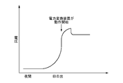
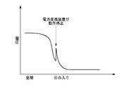
また、図3に示すように、朝方において、太陽電池10から出力される電力が徐々に大きくなり、電力変換装置20が動作を開始すると、電力変換装置20に入力される電圧は、急激に下がる。また、図4に示すように、夕方において、太陽電池10から出力される電力が徐々に小さくなり、電力変換装置20が停止すると、電力変換装置20に入力される電圧は、一端急激に上がったのち、下がる。このように、電力変換装置20に入力される電圧の変化により、電力変換装置20が停止しているか否かを判断できる。
そこで、停止判定部110は、電圧値取得部106により取得された電圧値Vinの変化が予め定められた条件を満たす場合に、電力変換装置20が停止していると判定してよい。停止判定部110は、電圧値取得部106により取得された電圧値Vinが徐々に大きくなっているものの、急激に下がる変化をまだ示していない場合、電圧値Vinが電力変換装置20が動作開始前の朝方の変化を示していると判断して、電力変換装置20が停止していると判定してよい。また、停止判定部110は、電圧値取得部106により取得された電圧値Vinが急激に上がったのち、下がる変化を示した場合、電力変換装置20が停止直後の夕方の変化を示していると判断して、電力変換装置20が停止していると判定してよい。
停止判定部110は、日射量取得部104により取得された日射量が予め定められた条件を満たし、かつ電圧値取得部106により取得された電圧値Vinの変化が予め定められた条件を満たす場合、電力変換装置20が停止していると判定してよい。停止判定部110は、日射量の変化が朝方、または夕方の変化を示し、電圧値Vinが、電力変換装置20が動作開始前の朝方の変化、または電力変換装置20が停止直後の夕方の変化を示す場合、電力変換装置20が停止していると判定してよい。
停止判定部110は、電圧値取得部により取得された電圧値Vinの変化が予め定められた条件を満たし、かつ現在のタイミングが予め定められた期間に含まれる場合、電力変換装置20が停止していると判定してよい。停止判定部110は、時刻取得部108により取得された現在の時刻が、予め定められた朝方の時間帯または夕方の時間帯に含まれ、かつ電圧値Vinが、電力変換装置20が動作開始前の朝方の変化、または電力変換装置20が停止直後の夕方の変化を示す場合、電力変換装置20が停止していると判定してよい。
停止判定部110は、電圧値Vin第1基準電圧値Vt1より大きく、かつ電圧値Vinの変化が予め定められた条件を満たす場合、電力変換装置20が停止していると判定してよい。停止判定部110は、電圧値Vinが、第1基準電圧値Vt1より大きく、かつ電圧値Vinの変化が予め定められた条件を満たし、現在のタイミングが予め定められた期間に含まれる場合、電力変換装置20が停止していると判定してよい。
本実施形態では、地絡検出部112は、電力変換装置20が停止していると停止判定部110が判定した場合に、太陽電池10の地絡を検出する。しかしながら、切断手段32に流れる電流が小さいときに、切断手段32を作動させられるのであれば、必ずしも電力変換装置20が停止していなくてもよい。
そこで、地絡検出部112は、電圧値取得部106により取得された電圧値Vinが第1基準電圧値Vt1より大きく、かつ第2基準電圧値Vt2より小さい場合、電力変換装置20が停止しているか否かを判定せずに、切断手段32によって太陽電池10と電力変換装置20とを電気的に切断させた状態で、太陽電池10の地絡を検出してもよい。地絡検出部112は、電圧値Vinが、第1基準電圧値Vt1より大きく、かつ電圧値Vinの変化が予め定められた条件を満たす場合、電力変換装置20が停止しているか否かを判定せずに、切断手段32によって太陽電池10と電力変換装置20とを電気的に切断させた状態で、太陽電池10の地絡を検出してもよい。
地絡検出部112は、電圧値取得部106により取得された電圧値Vinが、第1基準電圧値Vt1より大きく、かつ第2基準電圧値Vt2より小さく、現在のタイミングが予め定められた期間、例えば朝方の期間、または夕方の期間に含まれる場合、電力変換装置20が停止しているか否かを判定せずに、太陽電池10と電力変換装置20とを電気的に切断させた状態で、太陽電池10の地絡を検出してもよい。
地絡検出部112は、日射量取得部104により取得された日射量が予め定められた条件を満たす場合、例えば、日射量の変化が朝方の変化または夕方の変化を示す場合、電力変換装置20が停止しているか否かを判定せずに、切断手段32によって太陽電池10と電力変換装置20とを電気的に切断させた状態で、太陽電池10の地絡を検出してもよい。
地絡検出部112は、日射量取得部104により取得された日射量が予め定められた条件を満たし、かつ電圧値取得部106により取得された電圧値Vinが第1基準電圧値Vt1より大きく、かつ第2基準電圧値より小さい場合、切断手段32によって太陽電池10と電力変換装置20とを電気的に切断させた状態で、太陽電池10の地絡を検出してもよい。地絡検出部112は、日射量取得部104により取得された日射量の変化が朝方の変化または夕方の変化を示し、かつ電圧値Vinが第1基準電圧値Vt1より大きく、かつ第2基準電圧値Vt2より小さい場合、切断手段32によって太陽電池10と電力変換装置20とを電気的に切断させた状態で、太陽電池10の地絡を検出してもよい。
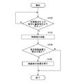
図5は、地絡検出装置30が、朝方に太陽電池10の地絡を検出する処理を実行する場合のフローチャートの一例を示す。
朝方、太陽電池10に照射される太陽光の量が徐々に大きくなり、太陽電池10から出力される電力が、制御部100を構成するマイクロコンピュータを起動させるのに十分な基準電力に達した場合(S100)、電源部44は、制御部100への電力の供給を開始し、制御部100が起動する(S102)。制御部100が起動すると、停止判定部110が、電力変換装置20が停止状態か否かを判定する(S104)。
停止判定部110は、電流値取得部102が取得した電流値I0、日射量取得部104が取得した日射量、電圧値取得部106が取得した電圧値Vin、および時刻取得部108が取得した現在時刻のうち少なくとも1つに基づいて、電力変換装置20が停止状態か否かを判定してよい。停止判定部110は、電流値取得部102が取得した電流値I0、日射量取得部104が取得した日射量、電圧値取得部106が取得した電圧値Vin、および時刻取得部108が取得した現在時刻のうち少なくとも2つに基づいて、電力変換装置20が停止状態か否かを判定してもよい。
停止判定部110は、電力変換装置20から電力変換装置20の動作状態を示す情報を取得して、取得した情報が、電力変換装置20が停止状態であることを示す場合に、電力変換装置20が停止状態であると判定してもよい。停止判定部110は、電力変換装置20から動作停止信号を受信した後、電力変換装置20から動作開始信号を受信していない場合に、電力変換装置20が停止状態であると判定してもよい。
電力変換装置20が停止状態であると停止判定部110が判定した場合、地絡検出部112が、電圧検出部40により検出された電圧V1、電圧V2、電圧V0に基づいて、式(5)に従って太陽電池10の絶縁抵抗200の抵抗値R0を導出し、抵抗値R0に基づいて、太陽電池10の地絡の有無を検出する(S106)。地絡検出部112は、抵抗値R0が予め定められた基準抵抗値Rt以上であれば、太陽電池10の地絡なしと判定する。地絡検出部112は、抵抗値R0が基準抵抗値Rt未満であれば、太陽電池10の地絡ありと判定する。
図6は、地絡検出装置30が、夕方に太陽電池10の地絡を検出する処理を実行する場合のフローチャートの一例を示す。
停止判定部110は、電力変換装置20が稼働状態から停止状態に移行したか否かを判定する(S200)。停止判定部110は、時刻取得部108が取得した現在の時刻が、夕方を示す予め定められた時間帯を示し、電圧値取得部106により取得された電圧値Vinが第2基準電圧値Vt2より小さい場合、電力変換装置20が稼働状態から停止状態に移行したと判定してもよい。停止判定部110は、日射量取得部104が取得した日射量の変化が夕方の日射量の変化を示し、電流値取得部102により取得された電圧値Vinが第2基準電圧値Vt2より小さい場合、電力変換装置20が稼働状態から停止状態に移行したと判定してもよい。停止判定部110は、時刻取得部108が取得した現在の時刻が、夕方を示す予め定められた時間帯を示し、電圧値取得部106が取得した電圧値Vinの変化が急激に上がったのち、下がる変化を示した場合、電力変換装置20が稼働状態から停止状態に移行したと判定してもよい。
停止判定部110が、電力変換装置20が稼働状態から停止状態に移行したと判定した場合、地絡検出部112は、太陽電池10からの電力が、太陽電池10の地絡を検出可能な基準電力より大きいか否かを判定する(S202)。地絡検出部112は、電流値取得部102が取得した電圧値Vinが第1基準電圧値Vt1より大きい場合、太陽電池10からの電力は太陽電池10の地絡を検出可能な基準電力より大きいと判定してよい。
太陽電池10からの電力が基準電力より大きい場合、地絡検出部112は、電圧検出部40により検出された電圧V1、電圧V2、電圧V0に基づいて、式(5)に従って太陽電池10の絶縁抵抗200の抵抗値R0を導出し、抵抗値R0に基づいて、太陽電池10の地絡の有無を検出する(S204)。地絡検出部112は、抵抗値R0が予め定められた基準抵抗値Rt以上であれば、太陽電池10の地絡なしと判定する。地絡検出部112は、抵抗値R0が基準抵抗値Rt未満であれば、太陽電池10の地絡ありと判定する。
以上の通り、本実施形態によれば、切断手段32に流れる電流が小さい場合に、切断手段32によって太陽電池10と電力変換装置20とを電気的に切断させた状態で、地絡検出部112が太陽電池10の地絡を検出する。よって、切断手段32に流れる電流が大きくなる場合を想定して、切断手段32を構成する部品として大電流にも耐える部品を選択しなくてよい。さらに言えば、切断手段32を構成するリレーとして大電流も耐えられる高価な部品を選択しなくてよい。また、切断手段32を構成するリレーを小型化できる。
以上、本発明を実施の形態を用いて説明したが、本発明の技術的範囲は上記実施の形態に記載の範囲には限定されない。上記実施の形態に、多様な変更または改良を加えることが可能であることが当業者に明らかである。その様な変更または改良を加えた形態も本発明の技術的範囲に含まれ得ることが、請求の範囲の記載から明らかである。
請求の範囲、明細書、および図面中において示した装置、システム、プログラム、および方法における動作、手順、ステップ、および段階等の各処理の実行順序は、特段「より前に」、「先立って」等と明示しておらず、また、前の処理の出力を後の処理で用いるのでない限り、任意の順序で実現しうることに留意すべきである。請求の範囲、明細書、および図面中の動作フローに関して、便宜上「まず、」、「次に、」等を用いて説明したとしても、この順で実施することが必須であることを意味するものではない。
10 太陽電池
20 電力変換装置
30 地絡検出装置
32 切断手段
34,36 スイッチ
38 抵抗
40 電圧検出部
44 電源部
100 制御部
102 電流値取得部
104 日射量取得部
106 電圧値取得部
108 時刻取得部
110 停止判定部
112 地絡検出部
114 条件格納部
20 電力変換装置
30 地絡検出装置
32 切断手段
34,36 スイッチ
38 抵抗
40 電圧検出部
44 電源部
100 制御部
102 電流値取得部
104 日射量取得部
106 電圧値取得部
108 時刻取得部
110 停止判定部
112 地絡検出部
114 条件格納部
Claims (20)
- 太陽電池からの電力を変換する電力変換装置が停止しているか否かを判定する停止判定部と、
前記停止判定部により前記電力変換装置が停止していると判定された場合に、前記太陽電池と前記電力変換装置との間に設けられた切断手段によって前記太陽電池と前記電力変換装置とを電気的に切断させた状態で、前記太陽電池の地絡を検出する地絡検出部と
を備える地絡検出装置。 - 前記太陽電池から出力される電圧の電圧値を取得する電圧値取得部をさらに備え、
前記地絡検出部は、前記電圧値取得部により取得された前記電圧値が第1基準電圧値より大きい場合に、前記太陽電池の地絡を検出する、請求項1に記載の地絡検出装置。 - 前記停止判定部は、前記電圧値取得部により取得された前記電圧値が、第2基準電圧値より小さい場合、前記電力変換装置が停止していると判定する、請求項2に記載の地絡検出装置。
- 前記停止判定部は、前記電圧値取得部により取得された前記電圧値が、第2基準電圧値より小さく、かつ現在のタイミングが予め定められた期間に含まれる場合、前記電力変換装置が停止していると判定する、請求項3に記載の地絡検出装置。
- 前記停止判定部は、前記電圧値取得部により取得された前記電圧値の変化が予め定められた条件を満たす場合、前記電力変換装置が停止していると判定する、請求項2に記載の地絡検出装置。
- 前記停止判定部は、前記電圧値取得部により取得された前記電圧値の変化が予め定められた条件を満たし、かつ現在のタイミングが予め定められた期間に含まれる場合、前記電力変換装置が停止していると判定する、請求項5に記載の地絡検出装置。
- 前記太陽電池から出力される電流の電流値を取得する電流値取得部をさらに備え、
前記停止判定部は、前記電圧値取得部により取得された前記電圧値が、第2基準電圧値より小さく、かつ前記電流値取得部により取得された前記電流値が、基準電流値より小さい場合、前記電力変換装置が停止していると判定する、請求項3に記載の地絡検出装置。 - 前記停止判定部は、前記電圧値取得部により取得された前記電圧値が、第2基準電圧値より小さく、前記電流値取得部により取得された前記電流値が、前記基準電流値より小さく、かつ現在のタイミングが予め定められた期間に含まれる場合、前記電力変換装置が停止していると判定する、請求項7に記載の地絡検出装置。
- 日射量を取得する日射量取得部をさらに備え、
前記停止判定部は、前記日射量取得部により取得された日射量が予め定められた条件を満たす場合、前記電力変換装置が停止していると判定する、請求項2に記載の地絡検出装置。 - 前記停止判定部は、前記日射量取得部により取得された日射量が予め定められた条件を満たし、かつ前記電圧値取得部により取得された前記電圧値が、第2基準電圧値より小さい場合、前記電力変換装置が停止していると判定する、請求項9に記載の地絡検出装置。
- 前記停止判定部は、前記日射量取得部により取得された日射量が予め定められた条件を満たし、かつ前記電圧値取得部により取得された前記電圧値の変化が予め定められた条件を満たす場合、前記電力変換装置が停止していると判定する、請求項9に記載の地絡検出装置。
- 前記太陽電池から出力される電流の電流値を取得する電流値取得部をさらに備え、
前記停止判定部は、前記日射量取得部により取得された日射量が予め定められた条件を満たし、前記電圧値取得部により取得された前記電圧値が、第2基準電圧値より小さく、かつ前記電流値取得部により取得された前記電流値が、基準電流値より小さい場合、前記電力変換装置が停止していると判定する、請求項10に記載の地絡検出装置。 - 太陽電池から出力される電圧の電圧値を取得する電圧値取得部と、
前記電圧値取得部により取得された前記電圧値が、第1基準電圧値より大きく、かつ第2基準電圧値より小さい場合、または、前記電圧値が、前記第1基準電圧値より大きく、かつ前記電圧値の変化が予め定められた条件を満たす場合、前記太陽電池と前記太陽電池からの電力を変換する電力変換装置との間に設けられた切断手段によって前記太陽電池と前記電力変換装置とを電気的に切断させた状態で、前記太陽電池の地絡を検出する地絡検出部と
を備える地絡検出装置。 - 前記地絡検出部は、前記電圧値取得部により取得された前記電圧値が、前記第1基準電圧値より大きく、かつ前記第2基準電圧値より小さく、現在のタイミングが予め定められた期間に含まれる場合、または、前記電圧値が、前記第1基準電圧値より大きく、かつ前記電圧値の変化が予め定められた条件を満たし、現在のタイミングが予め定められた期間に含まれる場合、前記切断手段によって前記太陽電池と前記電力変換装置とを電気的に切断させた状態で、前記太陽電池の地絡を検出する、請求項13に記載の地絡検出装置。
- 太陽電池から出力される電圧の電圧値を取得する電圧値取得部と、
前記太陽電池から出力される電流の電流値を取得する電流値取得部と、
前記電圧値取得部により取得された前記電圧値が、基準電圧値より大きく、かつ前記電流値取得部により取得された前記電流値が、基準電流値より小さい場合、前記太陽電池と前記太陽電池からの電力を変換する電力変換装置との間に設けられた切断手段によって前記太陽電池と前記電力変換装置とを電気的に切断させた状態で、前記太陽電池の地絡を検出する地絡検出部と
を備える地絡検出装置。 - 日射量を取得する日射量取得部と、
前記日射量取得部により取得された日射量が予め定められた条件を満たす場合、太陽電池と前記太陽電池からの電力を変換する電力変換装置との間に設けられた切断手段によって前記太陽電池と前記電力変換装置とを電気的に切断させた状態で、前記太陽電池の地絡を検出する地絡検出部と
を備える地絡検出装置。 - 前記太陽電池から出力される電流の電圧値を取得する電圧値取得部をさらに備え、
前記地絡検出部は、前記日射量取得部により取得された日射量が予め定められた条件を満たし、かつ前記電圧値取得部により取得された前記電圧値が第1基準電圧値より大きく、かつ第2基準電圧値より小さい場合、または、前記日射量が予め定められた条件を満たし、かつ前記電圧値が第1基準電圧値より大きく、前記電圧値の変化が予め定められた条件を満たす場合、前記切断手段によって前記太陽電池と前記電力変換装置とを電気的に切断させた状態で、前記太陽電池の地絡を検出する、請求項16に記載の地絡検出装置。 - 前記切断手段は、b接点を有するリレーである、請求項1から請求項17のいずれか1つに記載の地絡検出装置。
- 前記太陽電池からの電力を前記地絡検出装置に供給する電源部をさらに備える、請求項1から請求項18のいずれか1つに地絡検出装置。
- 請求項1から請求項19のいずれか1つの地絡検出装置としてコンピュータを機能させるためのプログラム。
Priority Applications (2)
| Application Number | Priority Date | Filing Date | Title |
|---|---|---|---|
| US15/103,022 US9991845B2 (en) | 2013-12-27 | 2014-12-10 | Ground fault detection device |
| DE112014006074.7T DE112014006074T5 (de) | 2013-12-27 | 2014-12-10 | Erdschlusserkennungsvorrichtung |
Applications Claiming Priority (2)
| Application Number | Priority Date | Filing Date | Title |
|---|---|---|---|
| JP2013-272530 | 2013-12-27 | ||
| JP2013272530A JP6337468B2 (ja) | 2013-12-27 | 2013-12-27 | 地絡検出装置 |
Publications (1)
| Publication Number | Publication Date |
|---|---|
| WO2015098523A1 true WO2015098523A1 (ja) | 2015-07-02 |
Family
ID=53478387
Family Applications (1)
| Application Number | Title | Priority Date | Filing Date |
|---|---|---|---|
| PCT/JP2014/082702 Ceased WO2015098523A1 (ja) | 2013-12-27 | 2014-12-10 | 地絡検出装置 |
Country Status (4)
| Country | Link |
|---|---|
| US (1) | US9991845B2 (ja) |
| JP (1) | JP6337468B2 (ja) |
| DE (1) | DE112014006074T5 (ja) |
| WO (1) | WO2015098523A1 (ja) |
Cited By (3)
| Publication number | Priority date | Publication date | Assignee | Title |
|---|---|---|---|---|
| CN108318765A (zh) * | 2016-05-25 | 2018-07-24 | 黄雪峰 | 一种电力故障诊断方法 |
| WO2018235278A1 (ja) * | 2017-06-23 | 2018-12-27 | 東芝三菱電機産業システム株式会社 | 電力変換装置の制御装置 |
| CN110488135A (zh) * | 2019-07-25 | 2019-11-22 | 中车永济电机有限公司 | 一种大功率永磁直驱机车变流器接地故障判断方法及定位策略 |
Families Citing this family (9)
| Publication number | Priority date | Publication date | Assignee | Title |
|---|---|---|---|---|
| CN105337519B (zh) * | 2015-11-18 | 2018-05-01 | 阳光电源股份有限公司 | 级联多电平变换器的自检系统及自检方法 |
| DE102016220030A1 (de) * | 2016-10-14 | 2018-04-19 | Robert Bosch Gmbh | Verfahren zum Erkennen eines Kurzschlusses über eine Last |
| US10998733B2 (en) * | 2017-07-04 | 2021-05-04 | Ingeteam Power Technology, S.A. | Power conversion system and associated control method |
| DE112018007008T5 (de) * | 2018-02-02 | 2020-11-05 | Sumitomo Electric Industries, Ltd. | Überwachungsvorrichtung und Bestimmungsverfahren |
| JP7196910B2 (ja) * | 2018-05-11 | 2022-12-27 | 住友電気工業株式会社 | 監視装置および監視方法 |
| KR102555504B1 (ko) * | 2018-06-12 | 2023-07-12 | 삼성에스디아이 주식회사 | 지락 검출 장치 및 그 방법 |
| JP7055777B2 (ja) * | 2019-07-12 | 2022-04-18 | 矢崎総業株式会社 | 検出装置 |
| DE102020121593A1 (de) * | 2020-08-18 | 2022-02-24 | Sma Solar Technology Ag | Photovoltaisch gespeiste elektrolyse |
| WO2022198659A1 (zh) * | 2021-03-26 | 2022-09-29 | 华为数字能源技术有限公司 | 一种供电设备及供电设备输入端的绝缘阻抗检测方法 |
Citations (6)
| Publication number | Priority date | Publication date | Assignee | Title |
|---|---|---|---|---|
| JPH0815345A (ja) * | 1994-04-30 | 1996-01-19 | Canon Inc | 絶縁状態測定方法、絶縁状態判定装置及びそれを用いた分散型発電システム |
| JPH10127071A (ja) * | 1996-10-21 | 1998-05-15 | Nissin Electric Co Ltd | 太陽光発電装置 |
| JP2000040838A (ja) * | 1998-07-24 | 2000-02-08 | Toshiba Corp | 太陽光発電設備の異常検出装置 |
| JP2001021606A (ja) * | 1999-07-07 | 2001-01-26 | Canon Inc | 地絡検出装置およびその方法、並びに、電源装置およびその制御方法 |
| JP2001298850A (ja) * | 2000-04-17 | 2001-10-26 | Tempearl Ind Co Ltd | 太陽光発電パネルの地絡検出装置 |
| JP2012119382A (ja) * | 2010-11-29 | 2012-06-21 | Jx Nippon Oil & Energy Corp | 地絡検出装置、地絡検出方法、太陽光発電システム、及び地絡検出プログラム |
Family Cites Families (1)
| Publication number | Priority date | Publication date | Assignee | Title |
|---|---|---|---|---|
| JP5642031B2 (ja) * | 2011-08-01 | 2014-12-17 | Jx日鉱日石エネルギー株式会社 | 地絡検出装置、地絡検出方法、太陽光発電システム、及び地絡検出プログラム |
-
2013
- 2013-12-27 JP JP2013272530A patent/JP6337468B2/ja not_active Expired - Fee Related
-
2014
- 2014-12-10 WO PCT/JP2014/082702 patent/WO2015098523A1/ja not_active Ceased
- 2014-12-10 US US15/103,022 patent/US9991845B2/en active Active
- 2014-12-10 DE DE112014006074.7T patent/DE112014006074T5/de not_active Withdrawn
Patent Citations (6)
| Publication number | Priority date | Publication date | Assignee | Title |
|---|---|---|---|---|
| JPH0815345A (ja) * | 1994-04-30 | 1996-01-19 | Canon Inc | 絶縁状態測定方法、絶縁状態判定装置及びそれを用いた分散型発電システム |
| JPH10127071A (ja) * | 1996-10-21 | 1998-05-15 | Nissin Electric Co Ltd | 太陽光発電装置 |
| JP2000040838A (ja) * | 1998-07-24 | 2000-02-08 | Toshiba Corp | 太陽光発電設備の異常検出装置 |
| JP2001021606A (ja) * | 1999-07-07 | 2001-01-26 | Canon Inc | 地絡検出装置およびその方法、並びに、電源装置およびその制御方法 |
| JP2001298850A (ja) * | 2000-04-17 | 2001-10-26 | Tempearl Ind Co Ltd | 太陽光発電パネルの地絡検出装置 |
| JP2012119382A (ja) * | 2010-11-29 | 2012-06-21 | Jx Nippon Oil & Energy Corp | 地絡検出装置、地絡検出方法、太陽光発電システム、及び地絡検出プログラム |
Cited By (11)
| Publication number | Priority date | Publication date | Assignee | Title |
|---|---|---|---|---|
| CN108318765A (zh) * | 2016-05-25 | 2018-07-24 | 黄雪峰 | 一种电力故障诊断方法 |
| CN108445325A (zh) * | 2016-05-25 | 2018-08-24 | 黄雪峰 | 一种电力故障诊断系统 |
| CN108469565A (zh) * | 2016-05-25 | 2018-08-31 | 黄雪峰 | 电力故障诊断方法及在电力故障诊断中的应用 |
| CN108445325B (zh) * | 2016-05-25 | 2020-09-04 | 西安兆腾测控技术有限公司 | 一种电力故障诊断系统 |
| WO2018235278A1 (ja) * | 2017-06-23 | 2018-12-27 | 東芝三菱電機産業システム株式会社 | 電力変換装置の制御装置 |
| CN110785905A (zh) * | 2017-06-23 | 2020-02-11 | 东芝三菱电机产业系统株式会社 | 电力转换装置的控制装置 |
| JPWO2018235278A1 (ja) * | 2017-06-23 | 2020-04-09 | 東芝三菱電機産業システム株式会社 | 電力変換装置の制御装置 |
| US11018495B2 (en) | 2017-06-23 | 2021-05-25 | Toshiba Mitsubishi-Electric Industrial Systems Corporation | Control device for electric power conversion apparatus |
| CN110785905B (zh) * | 2017-06-23 | 2022-04-01 | 东芝三菱电机产业系统株式会社 | 电力转换装置的控制装置 |
| CN110488135A (zh) * | 2019-07-25 | 2019-11-22 | 中车永济电机有限公司 | 一种大功率永磁直驱机车变流器接地故障判断方法及定位策略 |
| CN110488135B (zh) * | 2019-07-25 | 2021-06-22 | 中车永济电机有限公司 | 一种大功率永磁直驱机车变流器接地故障判断方法及定位策略 |
Also Published As
| Publication number | Publication date |
|---|---|
| DE112014006074T5 (de) | 2016-09-01 |
| JP2015128335A (ja) | 2015-07-09 |
| US20160380589A1 (en) | 2016-12-29 |
| US9991845B2 (en) | 2018-06-05 |
| JP6337468B2 (ja) | 2018-06-06 |
Similar Documents
| Publication | Publication Date | Title |
|---|---|---|
| JP6337468B2 (ja) | 地絡検出装置 | |
| JP5691891B2 (ja) | 太陽光発電用接続箱 | |
| EP3203597B1 (en) | Safety detection device and method of grid-connected inverter | |
| JP5920469B2 (ja) | 電源装置 | |
| EP3264550B1 (en) | Access control method for parallel direct current power supplies and device thereof | |
| US11394218B2 (en) | Controller, electricity storage system, and recording medium | |
| CN103901315B (zh) | 一种单极接地系统、接地保护及故障监测装置和方法 | |
| JP6394652B2 (ja) | 太陽光発電装置 | |
| CN106299180B (zh) | 电动工具和电池包的组合 | |
| JP6269299B2 (ja) | 地絡検出装置、電源システム、および地絡検出方法 | |
| EP3282578A1 (en) | Method and device for testing photovoltaic generation system | |
| CN112858839A (zh) | 电网接地故障检测系统、风电场系统及检测方法 | |
| JP6421494B2 (ja) | 制御装置、電力変換装置、電力システム、および制御方法 | |
| CN214585796U (zh) | 电网接地故障检测系统及风电场系统 | |
| US9373996B2 (en) | Inverting apparatus and photovoltaic power system using the same | |
| JP6054807B2 (ja) | センサ位置判定方法及びセンサ位置判定装置 | |
| JP2012085444A (ja) | 充放電システムの絶縁監視装置 | |
| JP6070305B2 (ja) | 制御装置、パワーコンディショナ、分散型電源システム、プログラム、および制御方法 | |
| JP6155983B2 (ja) | パワーコンディショナおよび分散型電源システム | |
| CN102969929B (zh) | 自动适应负载的逆变电源 | |
| JP2018125973A (ja) | 蓄電池制御装置 | |
| JP2018125974A (ja) | 蓄電池制御装置 | |
| KR101051257B1 (ko) | 직류 퓨즈 이상의 검출이 가능한 태양광 발전 시스템 및 직류 퓨즈 이상검출 장치 | |
| JP2014180113A (ja) | 制御装置、パワーコンディショナ、分散型電源システム、プログラム、および制御方法 |
Legal Events
| Date | Code | Title | Description |
|---|---|---|---|
| 121 | Ep: the epo has been informed by wipo that ep was designated in this application |
Ref document number: 14875240 Country of ref document: EP Kind code of ref document: A1 |
|
| WWE | Wipo information: entry into national phase |
Ref document number: 15103022 Country of ref document: US |
|
| WWE | Wipo information: entry into national phase |
Ref document number: 112014006074 Country of ref document: DE |
|
| 122 | Ep: pct application non-entry in european phase |
Ref document number: 14875240 Country of ref document: EP Kind code of ref document: A1 |