WO2015098340A1 - ユーザ端末、無線基地局、無線通信システムおよび無線通信方法 - Google Patents
ユーザ端末、無線基地局、無線通信システムおよび無線通信方法 Download PDFInfo
- Publication number
- WO2015098340A1 WO2015098340A1 PCT/JP2014/080073 JP2014080073W WO2015098340A1 WO 2015098340 A1 WO2015098340 A1 WO 2015098340A1 JP 2014080073 W JP2014080073 W JP 2014080073W WO 2015098340 A1 WO2015098340 A1 WO 2015098340A1
- Authority
- WO
- WIPO (PCT)
- Prior art keywords
- reception
- base station
- signal transmission
- terminals
- user terminal
- Prior art date
Links
Images


Classifications
-
- H—ELECTRICITY
- H04—ELECTRIC COMMUNICATION TECHNIQUE
- H04W—WIRELESS COMMUNICATION NETWORKS
- H04W72/00—Local resource management
- H04W72/04—Wireless resource allocation
- H04W72/044—Wireless resource allocation based on the type of the allocated resource
- H04W72/0453—Resources in frequency domain, e.g. a carrier in FDMA
-
- H—ELECTRICITY
- H04—ELECTRIC COMMUNICATION TECHNIQUE
- H04W—WIRELESS COMMUNICATION NETWORKS
- H04W48/00—Access restriction; Network selection; Access point selection
- H04W48/08—Access restriction or access information delivery, e.g. discovery data delivery
- H04W48/12—Access restriction or access information delivery, e.g. discovery data delivery using downlink control channel
-
- H—ELECTRICITY
- H04—ELECTRIC COMMUNICATION TECHNIQUE
- H04W—WIRELESS COMMUNICATION NETWORKS
- H04W52/00—Power management, e.g. TPC [Transmission Power Control], power saving or power classes
- H04W52/02—Power saving arrangements
- H04W52/0209—Power saving arrangements in terminal devices
- H04W52/0225—Power saving arrangements in terminal devices using monitoring of external events, e.g. the presence of a signal
- H04W52/0235—Power saving arrangements in terminal devices using monitoring of external events, e.g. the presence of a signal where the received signal is a power saving command
-
- H—ELECTRICITY
- H04—ELECTRIC COMMUNICATION TECHNIQUE
- H04W—WIRELESS COMMUNICATION NETWORKS
- H04W76/00—Connection management
- H04W76/10—Connection setup
- H04W76/14—Direct-mode setup
-
- H—ELECTRICITY
- H04—ELECTRIC COMMUNICATION TECHNIQUE
- H04W—WIRELESS COMMUNICATION NETWORKS
- H04W8/00—Network data management
- H04W8/005—Discovery of network devices, e.g. terminals
-
- Y—GENERAL TAGGING OF NEW TECHNOLOGICAL DEVELOPMENTS; GENERAL TAGGING OF CROSS-SECTIONAL TECHNOLOGIES SPANNING OVER SEVERAL SECTIONS OF THE IPC; TECHNICAL SUBJECTS COVERED BY FORMER USPC CROSS-REFERENCE ART COLLECTIONS [XRACs] AND DIGESTS
- Y02—TECHNOLOGIES OR APPLICATIONS FOR MITIGATION OR ADAPTATION AGAINST CLIMATE CHANGE
- Y02D—CLIMATE CHANGE MITIGATION TECHNOLOGIES IN INFORMATION AND COMMUNICATION TECHNOLOGIES [ICT], I.E. INFORMATION AND COMMUNICATION TECHNOLOGIES AIMING AT THE REDUCTION OF THEIR OWN ENERGY USE
- Y02D30/00—Reducing energy consumption in communication networks
- Y02D30/70—Reducing energy consumption in communication networks in wireless communication networks
Definitions
- the present invention relates to a user terminal, a radio base station, a radio communication system, and a radio communication method in a next generation mobile communication system.
- Non-Patent Document 1 In LTE (Long Term Evolution) and LTE successor systems (for example, LTE Advanced, FRA (Future Radio Access), 4G, etc.), D2D (Device to Device) allows terminals to communicate directly without going through a radio base station. ) Technology has been studied (for example, Non-Patent Document 1).
- D2D terminal When considering communication and discovery technology (D2D communication / discovery) between terminals, a terminal (D2D terminal) that performs D2D operation (direct signal transmission / reception between terminals including D2D communication and D2D discovery) exists in the network coverage. It is one of the important preconditions.
- the present invention has been made in view of such a point, and when performing D2D signal transmission / reception in a network including a plurality of frequencies, even if a frequency carrier having no area coverage is used as a resource for D2D signal transmission / reception, It is an object of the present invention to provide a user terminal, a radio base station, a radio communication system, and a radio communication method that can suppress an increase in power consumption of a D2D terminal.
- a user terminal is a user terminal capable of performing direct signal transmission / reception between terminals, and includes at least the resource information for direct signal transmission / reception between terminals transmitted from a connected or located radio base station The terminal in a second frequency carrier different from the first frequency carrier in which the inter-terminal direct signal transmission / reception resource information is transmitted based on the receiving unit for receiving information and the inter-terminal direct signal transmission / reception resource information And a control unit that controls to perform direct signal transmission / reception.
- the present invention when performing D2D signal transmission / reception in a network including a plurality of frequencies, even if a frequency carrier having no area coverage is used as a resource for D2D signal transmission / reception, it is efficient based on control from the network. D2D signal transmission / reception can be performed, and an increase in power consumption of the D2D terminal can be suppressed.
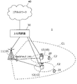
- FIG. 1A is a diagram illustrating an example in which a D2D terminal exists in the network coverage
- FIGS. 1B and 1C are diagrams illustrating an example in which the D2D terminal exists outside the network coverage. It is a figure explaining that a coverage differs for every frequency carrier. It is a figure explaining performing control of D2D signal transmission / reception with the cellular frequency carrier different from the frequency carrier which a D2D terminal uses as a D2D resource. In a 1st aspect, it is a figure explaining allocation of the resource for D2D signal transmission / reception in case a network has a some frequency carrier.
- a 1st aspect it is a figure explaining the case where the some carrier frequency for D2D is included in the system information which a cellular base station transmits.
- a 2nd aspect it is a figure explaining D2D signal transmission / reception between operators.
- a 2nd aspect it is a figure explaining the resource structure for D2D signal transmission / reception.
- a periodic uplink resource group is assigned to a D2D terminal as a D2D signal transmission / reception resource semi-statically.
- Each D2D terminal transmits a signal using a part of D2D signal transmission / reception resources.
- the D2D terminal finds another D2D terminal or performs communication by receiving the signal transmitted from the other D2D terminal from the resources for transmitting and receiving D2D signals.
- FIG. 1A is a diagram for explaining an example in which a D2D terminal exists in network coverage.
- the radio base station controls resources used by the D2D terminal in the coverage.
- the D2D terminal performs signal transmission / reception operation and the like according to network control.
- FIG. 1B and 1C are diagrams illustrating an example in which a D2D terminal exists outside the network coverage.
- a D2D terminal exists outside the network coverage
- a certain D2D terminal becomes a cluster head and controls other D2D terminals.
- Other D2D terminals perform signal transmission / reception operations and the like according to the control of the cluster head.
- a signal transmission / reception operation or the like is performed by individually controlling between D2D terminals.
- the use case and operation of D2D communication differ depending on whether the D2D terminal exists in the network coverage or not.
- the D2D terminal exists in the network coverage, for example, the use of a commercial use case, that is, the SNS (Social Networking Service) by the direct communication function (Proximity-based service) or the advertisement distribution is used for D2D. Signal transmission / reception is used.
- the network controls resources used by the D2D terminal.
- D2D signal transmission / reception is used as a public safety application, that is, an emergency communication in a disaster.
- autonomous operation of the D2D terminal or control between terminals is required.
- LTE and LTE advanced networks are assumed to have a configuration including not only a single frequency but also a plurality of frequencies in order to increase network capacity.
- a macro cell may use a carrier with a relatively low frequency band such as 2 [GHz]
- a small cell may use a carrier with a relatively high frequency band such as 3.5 [GHz].
- the coverage differs for each frequency carrier.
- the macro cell realizes wide coverage by using a low frequency band carrier.
- Rel. 8 to Rel. 11 existing terminals and Rel.
- a macro cell is operated at a frequency at which 12 terminals can be connected. Small cells are placed locally to cover high traffic areas.
- the macro base station forming the macro cell and the small base station forming the small cell are connected via a backhaul link. Specifically, it is assumed that the macro base station cooperates with the small base station via the backhaul, and the macro base station assists the small base station, that is, the macro base station subordinates the small base station. The It is assumed that a plurality of small base stations are connected via a backhaul link.
- the uplink resource of the macro cell frequency takes advantage of its wide coverage and backward compatibility. 8 to Rel. 11 existing terminals and Rel. It is assumed that it is used for 12 terminals and VoIP (Voice over Internet Protocol). Therefore, the uplink resource of the macro cell frequency has no margin and is not suitable for use as a resource for D2D signal transmission / reception.
- a small cell using a new high frequency band is Rel. 8 to Rel. It is assumed that uplink resources have a relatively large margin, such as existing terminals up to 11 are not connected. Therefore, it is preferable to use a small cell frequency as a resource for transmitting and receiving D2D signals.
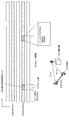
- a small cell does not have a planar coverage. Therefore, as shown in FIG. 2, it is assumed that many D2D terminals existing in the macro cell coverage exist outside the small cell coverage. In this case, if a small cell frequency is used as a resource for transmitting and receiving D2D signals, an operation is performed when many D2D terminals exist outside the coverage. Specifically, the D2D terminal performs resource control of other D2D terminals using the own terminal as a cluster head. The D2D terminal that has become the cluster head has an inefficient operation such as an increase in power consumption.
- the present inventors have found that D2D signal transmission / reception is controlled by a cellular frequency carrier different from the frequency carrier used by the D2D terminal as a resource for D2D signal transmission / reception. Thereby, the cluster head operation of the D2D terminal in the network coverage becomes unnecessary, and the power consumption of the D2D terminal can be reduced.
- the macro cell frequency for example, 2 [ GHz]
- the macro cell controls resources used by the D2D terminal.
- the frequency carrier and network used for D2D signal transmission / reception are used.
- a mechanism is required to operate even if the frequency carrier to be controlled is different. Therefore, the present invention is not limited to the case where the D2D terminal performs D2D signal transmission / reception using the small cell frequency as the D2D signal transmission / reception resource.
- Resource scheduling will be described.
- D2D signal transmission / reception resources As a D2D signal transmission / reception resource, a part of uplink resources of normal cellular communication is used. In order to avoid interference, the resources of the cellular communication signal and the D2D signal are time division multiplexed (TDM).
- TDM time division multiplexed
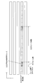
- a cellular base station such as a macro cell notifies the D2D signal transmission / reception resource allocation information to D2D terminals in the area using system information included and transmitted in a system information block type x (SIBx: System Information Block). To do.
- the D2D signal transmission / reception resource allocation information includes the carrier frequency (carrierFreq-D2D) and time domain resource information of the D2D signal transmission / reception resource.
- the cellular base station may notify the D2D signal transmission / reception resource allocation information to the D2D terminals in the area using higher layer signaling such as RRC (Radio Resource Control) signaling.
- RRC Radio Resource Control
- the time domain resource information includes the top frame number, the subframe offset value, the number of subframes, the D2D resource period, and the like.
- the cellular base station uses the system information to notify all the D2D terminals in the area of the allocation information of the resource for D2D signal transmission / reception, so that all the terminals in the area including the idle terminal have the same time frequency resource as D2D. Recognized as a signal transmission / reception resource.
- the terminal transmits / receives the D2D signal according to the allocation information of the resource for transmitting / receiving the D2D signal included in the system information of the connected or located cell.
- D2D synchronization (D2D synchronization) after receiving system information from the cellular base station
- D2D terminal that has received the system information performs synchronization for D2D signal transmission / reception.
- the D2D terminal synchronizes D2D signal transmission / reception resources using PSS / SSS (Primary Synchronization Signal / Secondary Synchronization Signal) which is a synchronization signal of the macro cell as a synchronization source.
- PSS / SSS Primary Synchronization Signal / Secondary Synchronization Signal
- all D2D terminals in the macro cell coverage can use the same synchronization timing.
- the D2D terminal detects the synchronization signal at the small cell frequency and synchronizes the resources for transmitting and receiving the D2D signal.
- the D2D terminal uses the PSS / SSS transmitted by the small cell as a synchronization source and transmits and receives the D2D signal Synchronize Further, the D2D terminal transmits a D2D synchronization signal (PD2DSS: Physical D2D Syncronization Signal).
- P2DSS Physical D2D Syncronization Signal
- D2D signal transmission / reception resources are synchronized using a D2D synchronization signal (PD2DSS) transmitted by the D2D terminal as a synchronization source.
- P2DSS D2D synchronization signal
- the macro cell and the small cell are operated asynchronously, and the D2D terminal is outside the small cell coverage and is located far from the small cell, and the small cell transmits the PSS / SSS and the small cell coverage.
- the D2D terminals synchronize the resources for D2D signal transmission / reception with the PSS / SSS transmitted by the macro cell as a synchronization source.
- the D2D terminal that is in the small cell coverage or outside the small cell coverage but is in the vicinity of the small cell coverage uses the same timing synchronized with the downlink timing of the small cell to synchronize the resources for D2D signal transmission / reception. use.
- interference with cellular uplink communication can be avoided by time division multiplexing.
- a D2D terminal that is outside the small cell coverage and is far from the small cell coverage uses a unique timing such as a macro cell downlink timing for synchronization of D2D signal transmission / reception resources.
- a unique timing such as a macro cell downlink timing for synchronization of D2D signal transmission / reception resources.
- the interference with the cellular uplink communication at the small cell frequency is not a problem because the small cell and the D2D terminal are geographically separated.
- a D2D terminal existing at a position far from such a small cell coverage cannot transmit / receive a D2D signal to / from a D2D terminal existing in or near the small cell coverage.
- the D2D terminal that exists far from the small cell coverage is located in the small cell coverage or a position that is close to the D2D terminal that exists in the vicinity of the small cell coverage, the D2D terminal that is originally present in the small cell coverage Should be able to detect the D2D synchronization signal (PD2DSS) transmitted.
- P2DSS D2D synchronization signal
- D2D synchronization signal (PD2DSS) is geographically distant from other D2D terminals in the first place, and is not in an environment where D2D signals can be transmitted and received. It will be.
- SC-FDMA Single Carrier-Frequency Division Multiple Access
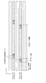
- the cellular base station When a plurality of D2D carrier frequencies are included in system information transmitted by a cellular base station such as a macro cell, the cellular base station notifies D2D signal transmission / reception resources used for D2D transmission or reception (D2D transmission / reception). In addition, a D2D carrier is designated.
- the system information transmitted by the cellular base station includes two carrier frequencies of D2D carriers # 1 and # 2.
- the cellular base station when notifying the resource index #a used for D2D transmission or reception (D2D transmission / reception), the cellular base station also specifies the D2D carrier # 2 including the resource index #a.
- the D2D carrier is notified using, for example, a CIF (Carrier Indicator Field) in carrier aggregation.
- CIF Carrier Indicator Field
- the D2D terminal within the network coverage is controlled.
- the cluster head operation is unnecessary, and the power consumption of the D2D terminal can be reduced.
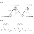
- D2D signal transmission / reception should not be limited to operations within a single operator. If D2D signal transmission / reception between different operators is not supported, the use cases for D2D signal transmission / reception are very limited.
- a different frequency is set as a D2D carrier for each operator, except when a frequency shared between operators is used as a D2D carrier (see FIG. 6B).
- the D2D terminal receives not only the D2D signal transmission / reception on the operator's D2D carrier contracted by the terminal itself but also the D2D signal reception on the other operator's D2D carrier. Must be supported at least (see FIG. 6A).
- the D2D terminal In order for the D2D terminal to receive the D2D signal on the other operator's D2D carrier, the D2D terminal needs to know the other operator's D2D carrier and D2D signal transmission / reception resource configuration.
- the D2D terminal In an operation in which D2D signal transmission / reception resources are allocated in a completely asynchronous manner between operators, the D2D terminal must hold a plurality of synchronization sources and perform observations at a plurality of timings for transmission / reception of D2D signals between operators. This method is not practical from the viewpoint of power consumption and efficiency of the D2D terminal, such as a longer period during which the D2D terminal performs observation.
- the D2D terminal recognizes the configuration of D2D signal transmission / reception resources of other operators as follows.
- the D2D terminal scans the entire supported band and recognizes the D2D carrier and time domain resource information of each operator. For signal transmission in D2D signal transmission / reception, the D2D terminal uses D2D signal transmission / reception resources in the frequency carrier of the operator with whom the terminal is contracted. The D2D terminal also uses the D2D signal transmission / reception resources in the frequency carrier of the recognized other operator for signal reception in the D2D signal transmission / reception.
- the D2D terminal is based on the premise that a plurality of frequency carriers for D2D cannot be observed at the same time, the resources for transmitting and receiving D2D signals need to be shifted in time between operators (see FIG. 7).
- the position of the D2D signal transmission / reception resource is temporally shifted between the operator A D2D carrier and the operator B D2D carrier.
- the D2D terminal does not observe the frequency carrier adopting the configuration in which the resource for D2D signal transmission / reception is set at a position apart from the resource for D2D signal transmission / reception of the operator contracted by the terminal at a certain time or more.
- the D2D carrier of the operator with whom the terminal is contracted and the D2D carrier of another operator are assumed to be in asynchronous operation, resulting in a significant increase in power consumption.
- FIG. 8 is a schematic configuration diagram showing an example of a radio communication system according to the present embodiment.
- the radio communication system 1 is in a cell formed by a plurality of radio base stations 10 (11 and 12) and each radio base station 10, and is configured to be able to communicate with each radio base station 10.
- Each of the radio base stations 10 is connected to the higher station apparatus 30 and connected to the core network 40 via the higher station apparatus 30.
- the radio base station 11 is composed of, for example, a macro base station having a relatively wide coverage, and forms a macro cell C1.
- the radio base station 12 is configured by a small base station having local coverage, and forms a small cell C2.
- the number of radio base stations 11 and 12 is not limited to the number shown in FIG.
- the same frequency band may be used, or different frequency bands may be used.
- the radio base stations 11 and 12 are connected to each other via an inter-base station interface (for example, optical fiber, X2 interface).
- the user terminal 20 is a terminal that supports various communication methods such as LTE and LTE-A, and may include not only a mobile communication terminal but also a fixed communication terminal.
- the user terminal 20 can execute communication with other user terminals 20 via the radio base station 10. Further, the user terminal 20 can execute direct communication (D2D) with other user terminals 20 without going through the radio base station 10.
- D2D direct communication
- the upper station apparatus 30 includes, for example, an access gateway apparatus, a radio network controller (RNC), a mobility management entity (MME), and the like, but is not limited thereto.
- RNC radio network controller
- MME mobility management entity
- a downlink shared channel (PDSCH: Physical Downlink Shared Channel) shared by each user terminal 20, a downlink control channel (PDCCH: Physical Downlink Control Channel, EPDCCH: Enhanced Physical Downlink Control Channel). ), A broadcast channel (PBCH) or the like is used.
- PDSCH Physical Downlink Shared Channel
- PDCCH Physical Downlink Control Channel
- EPDCCH Enhanced Physical Downlink Control Channel
- PBCH broadcast channel
- DCI Downlink control information
- an uplink shared channel (PUSCH: Physical Uplink Shared Channel) shared by each user terminal 20, an uplink control channel (PUCCH: Physical Uplink Control Channel), or the like is used as an uplink channel.
- PUSCH Physical Uplink Shared Channel
- PUCCH Physical Uplink Control Channel
- User data and higher layer control information are transmitted by PUSCH.
- discovery signals for detecting each other are transmitted between the user terminals 20 in the uplink.
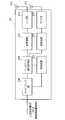
- FIG. 9 is an overall configuration diagram of the radio base station 10 according to the present embodiment.
- the radio base station 10 includes a plurality of transmission / reception antennas 101 for MIMO (Multiple Input Multiple Output) transmission, an amplifier unit 102, a transmission / reception unit 103, a baseband signal processing unit 104, a call processing unit 105, and an interface unit. 106.
- MIMO Multiple Input Multiple Output
- User data transmitted from the radio base station 10 to the user terminal 20 via the downlink is input from the higher station apparatus 30 to the baseband signal processing unit 104 via the interface unit 106.
- PDCP Packet Date Convergence Protocol
- RLC Radio Link Control
- MAC Medium Access Control
- HARQ Hybrid ARQ
- IFFT Inverse Fast Fourier Transform
- precoding processing is performed, and each transmission / reception section 103 Forwarded to
- the downlink control signal is also subjected to transmission processing such as channel coding and inverse fast Fourier transform, and is transferred to each transmitting / receiving unit 103.
- Each transmission / reception unit 103 converts the downlink signal output from the baseband signal processing unit 104 by precoding for each antenna to a radio frequency band.
- Each amplifier unit 102 amplifies the frequency-converted radio frequency signal and transmits it by each transmitting / receiving antenna 101.
- the radio frequency signal received by each transmitting / receiving antenna 101 is amplified by the amplifier unit 102, frequency-converted by each transmitting / receiving unit 103, converted into a baseband signal, and sent to the baseband signal processing unit 104. Entered.
- Each transmission / reception unit 103 notifies each user terminal 20 of the D2D discovery resource group.
- Each transmitting / receiving unit 103 transmits, to each user terminal 20, initial allocation position information of resources for transmitting discovery signals used for D2D discovery.
- Each transmission / reception part 103 notifies each user terminal 20 of a prior rule.
- the baseband signal processing unit 104 performs FFT (Fast Fourier Transform) processing, IDFT processing, error correction decoding, MAC retransmission control reception processing, RLC layer, PDCP layer processing on user data included in the input uplink signal. Reception processing is performed, and the data is transferred to the upper station apparatus 30 via the interface unit 106.
- the call processing unit 105 performs call processing such as communication channel setting and release, state management of the radio base station 10, and radio resource management.
- the interface unit 106 transmits and receives signals (backhaul signaling) to and from adjacent radio base stations via an inter-base station interface (for example, an optical fiber or an X2 interface). Alternatively, the interface unit 106 transmits and receives signals to and from the higher station apparatus 30 via a predetermined interface.
- an inter-base station interface for example, an optical fiber or an X2 interface.
- the interface unit 106 transmits and receives signals to and from the higher station apparatus 30 via a predetermined interface.
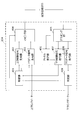
- FIG. 10 is a main functional configuration diagram of the baseband signal processing unit 104 included in the radio base station 10 according to the present embodiment.
- the baseband signal processing unit 104 included in the radio base station 10 includes a control unit 301, a downlink control signal generation unit 302, a downlink data signal generation unit 303, a mapping unit 304, and a demapping unit. 305, a channel estimation unit 306, an uplink control signal decoding unit 307, an uplink data signal decoding unit 308, and a determination unit 309 are included.
- the control unit 301 controls scheduling of downlink user data transmitted on the PDSCH, downlink control information transmitted on both or either of the PDCCH and the extended PDCCH (EPDCCH), downlink reference signals, and the like.
- the control unit 301 controls the RA preamble transmitted by the PRACH (Physical Radio Access Channel), the uplink data transmitted by the PUSCH, the uplink control information transmitted by the PUCCH or the PUSCH, and the scheduling control (allocation control) of the uplink reference signal. ).
- Information related to allocation control of uplink signals (uplink control signals, uplink user data) is notified to the user terminal 20 using downlink control signals (DCI: Downlink Contrl Information).
- the control unit 301 controls allocation of radio resources to the downlink signal and the uplink signal based on the instruction information from the higher station apparatus 30 and the feedback information from each user terminal 20. That is, the control unit 301 has a function as a scheduler.
- the control unit 301 controls the user terminal 20 to notify system information including at least resource information for D2D signal transmission / reception.
- the control unit 301 notifies the user terminal 20 of the synchronization information of the frequency carrier on which the user terminal 20 executes D2D signal transmission / reception and the frequency carrier that controls the D2D signal transmission / reception on the user terminal 20 in the system information. Control as follows.
- the downlink control signal generation unit 302 generates a downlink control signal (both PDCCH signal and EPDCCH signal or one of them) whose assignment is determined by the control unit 301. Specifically, the downlink control signal generation unit 302 generates a downlink assignment for notifying downlink signal allocation information and an UL grant for notifying uplink signal allocation information based on an instruction from the control unit 301. To do.
- the downlink data signal generation unit 303 generates a downlink data signal (PDSCH signal) determined to be allocated to resources by the control unit 301.
- the data signal generated by the downlink data signal generation unit 303 is subjected to coding processing and modulation processing according to the coding rate and modulation method determined based on CSI (Channel State Information) from each user terminal 20 and the like. .
- CSI Channel State Information
- the mapping unit 304 allocates the downlink control signal generated by the downlink control signal generation unit 302 and the downlink data signal generated by the downlink data signal generation unit 303 to radio resources. Control.
- the demapping unit 305 demaps the uplink signal transmitted from the user terminal 20 and separates the uplink signal.
- Channel estimation section 306 estimates the channel state from the reference signal included in the received signal separated by demapping section 305, and outputs the estimated channel state to uplink control signal decoding section 307 and uplink data signal decoding section 308.
- the uplink control signal decoding unit 307 decodes a feedback signal (such as a delivery confirmation signal) transmitted from the user terminal through the uplink control channel (PRACH, PUCCH) and outputs the decoded signal to the control unit 301.
- Uplink data signal decoding section 308 decodes the uplink data signal transmitted from the user terminal through the uplink shared channel (PUSCH), and outputs the decoded signal to determination section 309.
- the determination unit 309 performs retransmission control determination (A / N determination) based on the decoding result of the uplink data signal decoding unit 308 and outputs the result to the control unit 301.
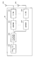
- FIG. 11 is an overall configuration diagram of the user terminal 20 according to the present embodiment.
- the user terminal 20 includes a plurality of transmission / reception antennas 201 for MIMO transmission, an amplifier unit 202, a transmission / reception unit (reception unit) 203, a baseband signal processing unit 204, an application unit 205, It is equipped with.
- radio frequency signals received by a plurality of transmission / reception antennas 201 are each amplified by an amplifier unit 202, converted in frequency by a transmission / reception unit 203, and converted into a baseband signal.
- the baseband signal is subjected to FFT processing, error correction decoding, retransmission control reception processing, and the like by the baseband signal processing unit 204.
- downlink user data is transferred to the application unit 205.
- the application unit 205 performs processing related to layers higher than the physical layer and the MAC layer.
- broadcast information in the downlink data is also transferred to the application unit 205.
- uplink user data is input from the application unit 205 to the baseband signal processing unit 204.
- the baseband signal processing unit 204 transmission processing of retransmission control (HARQ: Hybrid ARQ), channel coding, precoding, DFT processing, IFFT processing, and the like are performed and transferred to each transmission / reception unit 203.
- the transmission / reception unit 203 converts the baseband signal output from the baseband signal processing unit 204 into a radio frequency band. Thereafter, the amplifier unit 202 amplifies the frequency-converted radio frequency signal and transmits the amplified signal using the transmitting / receiving antenna 201.
- the transmission / reception unit 203 receives system information including at least D2D signal transmission / reception resource information transmitted from the connected or located radio base station 10.
- the transmission / reception unit 203 transmits a signal using a part of the specified D2D signal transmission / reception resource in the specified frequency carrier.
- the transmission / reception unit 203 receives a signal transmitted from another user terminal 20 from among resources for transmitting / receiving D2D signals.
- FIG. 12 is a main functional configuration diagram of the baseband signal processing unit 204 included in the user terminal 20.
- the baseband signal processing unit 204 included in the user terminal 20 includes a control unit 401, an uplink control signal generation unit 402, an uplink data signal generation unit 403, a mapping unit 404, and a demapping unit 405.
- the control unit 401 determines the uplink control signal (A / N signal, etc.) and the uplink data signal. Control generation.
- the downlink control signal received from the radio base station is output from the downlink control signal decoding unit 407, and the retransmission control determination result is output from the determination unit 409.
- the control unit 401 controls the allocation of the signal in the D2D signal transmission / reception to the D2D signal transmission / reception resource based on the D2D signal transmission / reception resource information notified from the radio base station 10.
- the control unit 401 controls synchronization of D2D signal transmission / reception resources based on the system information.
- the uplink control signal generation unit 402 generates an uplink control signal (feedback signal such as a delivery confirmation signal or channel state information (CSI)) based on an instruction from the control unit 401.
- Uplink data signal generation section 403 generates an uplink data signal based on an instruction from control section 401. Note that the control unit 401 instructs the uplink data signal generation unit 403 to generate an uplink data signal when the UL grant is included in the downlink control signal notified from the radio base station.
- the mapping unit 404 controls allocation of uplink control signals (delivery confirmation signals and the like) and uplink data signals to radio resources (PUCCH, PUSCH) based on an instruction from the control unit 401. Based on an instruction from the control unit 401, the mapping unit 404 controls allocation of signals in D2D signal transmission / reception to resources for D2D signal transmission / reception.
- the demapping unit 405 demaps the downlink signal transmitted from the radio base station 10 and separates the downlink signal.
- Channel estimation section 406 estimates the channel state from the reference signal included in the received signal separated by demapping section 405, and outputs the estimated channel state to downlink control signal decoding section 407 and downlink data signal decoding section 408.
- the downlink control signal decoding unit 407 decodes the downlink control signal (PDCCH signal) transmitted on the downlink control channel (PDCCH), and outputs scheduling information (allocation information to uplink resources) to the control unit 401. Also, when the downlink control signal includes information on a cell that feeds back a delivery confirmation signal and information on whether or not RF (Radio Frequency) adjustment is applied, the information is also output to the control unit 401.
- RF Radio Frequency
- the downlink data signal decoding unit 408 decodes the downlink data signal transmitted through the downlink shared channel (PDSCH), and outputs the decoded signal to the determination unit 409.
- the determination unit 409 performs retransmission control determination (A / N determination) based on the decoding result of the downlink data signal decoding unit 408 and outputs the result to the control unit 401.
Abstract
Description
第1の態様では、D2D端末がD2D信号送受信用リソースとして使用する周波数キャリアとは異なるセルラ周波数キャリアによって、D2D信号送受信を制御する方法における、D2D信号送受信用リソースの割り当て、D2D同期およびD2D信号送受信用リソースのスケジューリングについて説明する。
第2の態様では、異なるオペレータ間におけるD2D信号送受信の制御について説明する。
以下、本実施の形態に係る無線通信システムの構成について説明する。この無線通信システムでは、上記第1の態様および第2の態様に係る無線通信方法が適用される。
Claims (10)
- 端末間直接信号送受信を実行可能なユーザ端末であって、
接続中または在圏中の無線基地局から送信される、前記端末間直接信号送受信用リソース情報を少なくとも含むシステム情報を受信する受信部と、
前記端末間直接信号送受信用リソース情報に基づいて、前記端末間直接信号送受信用リソース情報が送信された第1の周波数キャリアとは異なる第2の周波数キャリアにおいて前記端末間直接信号送受信を行うよう制御する制御部と、を備えることを特徴とするユーザ端末。 - 前記制御部は、前記システム情報に含まれる前記第1の周波数キャリアと前記第2の周波数キャリアとの同期状態情報に基づいて、前記端末間直接信号送受信を行う際の同期ソースを決定することを特徴とする請求項1に記載のユーザ端末。
- 前記ユーザ端末は、マクロ基地局および前記マクロ基地局配下の複数のスモール基地局から送信される下りリンク信号を受信可能であり、
前記制御部は、前記マクロ基地局と前記スモール基地局とが同期運用されている場合には、前記マクロ基地局が送信する同期信号を前記同期ソースとして決定することを特徴とする請求項2に記載のユーザ端末。 - 前記ユーザ端末は、マクロ基地局および前記マクロ基地局配下の複数のスモール基地局から送信される下りリンク信号を受信可能であり、
前記制御部は、前記マクロ基地局と前記スモール基地局とが非同期運用されており、かつ、自端末が前記スモール基地局と接続中または在圏中である場合には、前記スモール基地局が送信する同期信号を前記同期ソースとして決定し、自端末が同期信号を送信することを特徴とする請求項2に記載のユーザ端末。 - 前記ユーザ端末は、マクロ基地局および前記マクロ基地局配下の複数のスモール基地局から送信される下りリンク信号を受信可能であり、
前記制御部は、前記マクロ基地局と前記スモール基地局とが非同期運用されており、かつ、自端末が前記スモール基地局と接続中または在圏中でない場合には、前記スモール基地局と接続中または在圏中のユーザ端末が送信する同期信号またはマクロ基地局が送信する同期信号を前記同期ソースとして決定することを特徴とする請求項2に記載のユーザ端末。 - 端末間直接信号送受信を実行可能なユーザ端末と通信可能な無線基地局であって、
前記ユーザ端末に対して、前記端末間直接信号送受信用リソース情報を少なくとも含むシステム情報を通知する制御部を備え、
前記ユーザ端末に対して前記端末間直接信号送受信を制御する第1の周波数キャリアと、前記端末間直接信号送受信用リソースが割り当てられる第2の周波数キャリアとが、異なる周波数キャリアであることを特徴とする無線基地局。 - 前記制御部は、前記第1の周波数キャリアと前記第2の周波数キャリアとの同期状態情報を前記システム情報に含めて前記ユーザ端末に通知することを特徴とする請求項6に記載の無線基地局。
- 上位レイヤシグナリングまたは制御チャネルを用いて、前記第2の周波数キャリアを前記端末間直接信号送受信用リソース情報とともに前記ユーザ端末に通知することを特徴とする請求項6または請求項7に記載の無線基地局。
- 端末間直接信号送受信を実行可能なユーザ端末と、前記ユーザ端末と通信可能な無線基地局とを含む無線通信システムであって、
前記無線基地局は、前記ユーザ端末に対して、前記端末間直接信号送受信用リソース情報を少なくとも含むシステム情報を通知する制御部を備え、
前記ユーザ端末は、接続中または在圏中の前記無線基地局から送信される、前記端末間直接信号送受信用リソース情報を少なくとも含むシステム情報を受信する受信部と、
前記端末間直接信号送受信用リソース情報に基づいて、前記端末間直接信号送受信用リソース情報が送信された第1の周波数キャリアとは異なる第2の周波数キャリアにおいて前記端末間直接信号送受信を行うよう制御する制御部と、を備えることを特徴とする無線通信システム。 - 端末間直接信号送受信を実行可能なユーザ端末の無線通信方法であって、
接続中または在圏中の無線基地局から送信される、前記端末間直接信号送受信用リソース情報を少なくとも含むシステム情報を受信する工程と、
前記端末間直接信号送受信用リソース情報に基づいて、前記端末間直接信号送受信用リソース情報が送信された第1の周波数キャリアとは異なる第2の周波数キャリアにおけるリソースを用いて前記端末間直接信号送受信を行う工程と、を備えることを特徴とする無線通信方法。
Priority Applications (5)
| Application Number | Priority Date | Filing Date | Title |
|---|---|---|---|
| EP14874819.7A EP3089531B1 (en) | 2013-12-26 | 2014-11-13 | User terminal and radio communication method |
| CN201911021515.9A CN110740518B (zh) | 2013-12-26 | 2014-11-13 | 终端、无线通信方法 |
| US15/107,162 US10631294B2 (en) | 2013-12-26 | 2014-11-13 | User terminal, radio base station, radio communication system and radio communication method |
| PL14874819.7T PL3089531T3 (pl) | 2013-12-26 | 2014-11-13 | Terminal użytkownika i sposób łączności radiowej |
| CN201480070546.2A CN105900508A (zh) | 2013-12-26 | 2014-11-13 | 用户终端、无线基站、无线通信系统以及无线通信方法 |
Applications Claiming Priority (2)
| Application Number | Priority Date | Filing Date | Title |
|---|---|---|---|
| JP2013269756A JP2015126393A (ja) | 2013-12-26 | 2013-12-26 | ユーザ端末、無線基地局、無線通信システムおよび無線通信方法 |
| JP2013-269756 | 2013-12-26 |
Publications (1)
| Publication Number | Publication Date |
|---|---|
| WO2015098340A1 true WO2015098340A1 (ja) | 2015-07-02 |
Family
ID=53478216
Family Applications (1)
| Application Number | Title | Priority Date | Filing Date |
|---|---|---|---|
| PCT/JP2014/080073 WO2015098340A1 (ja) | 2013-12-26 | 2014-11-13 | ユーザ端末、無線基地局、無線通信システムおよび無線通信方法 |
Country Status (6)
| Country | Link |
|---|---|
| US (1) | US10631294B2 (ja) |
| EP (1) | EP3089531B1 (ja) |
| JP (1) | JP2015126393A (ja) |
| CN (2) | CN110740518B (ja) |
| PL (1) | PL3089531T3 (ja) |
| WO (1) | WO2015098340A1 (ja) |
Cited By (3)
| Publication number | Priority date | Publication date | Assignee | Title |
|---|---|---|---|---|
| WO2017033486A1 (en) * | 2015-08-21 | 2017-03-02 | Nec Corporation | Vehicle to everything (v2x) communication method and system |
| CN108029153A (zh) * | 2015-08-13 | 2018-05-11 | 意大利电信股份公司 | 用于启用plmn间接近服务的方法和系统 |
| CN111279737A (zh) * | 2017-09-08 | 2020-06-12 | 株式会社Ntt都科摩 | 用户终端以及无线通信方法 |
Families Citing this family (14)
| Publication number | Priority date | Publication date | Assignee | Title |
|---|---|---|---|---|
| WO2015198490A1 (ja) * | 2014-06-27 | 2015-12-30 | 富士通株式会社 | 通信システム、基地局及び通信端末 |
| JP2016096475A (ja) * | 2014-11-14 | 2016-05-26 | Kddi株式会社 | 無線制御装置、端末装置、および通信方法 |
| WO2016208098A1 (ja) * | 2015-06-25 | 2016-12-29 | 日本電気株式会社 | D2d通信制御装置、無線端末、中継無線端末候補選択方法及び非一時的なコンピュータ可読媒体 |
| EP3322233B1 (en) | 2015-07-09 | 2020-09-09 | LG Electronics Inc. | Synchronization method of user equipment in wireless communication system and user equipment using method |
| CN106454746B (zh) | 2015-08-13 | 2020-06-26 | 华为技术有限公司 | 设备到设备通信方法、装置和系统 |
| JPWO2017026543A1 (ja) * | 2015-08-13 | 2018-05-31 | 株式会社Nttドコモ | ユーザ装置、及びd2d信号送信方法 |
| CN107645392B (zh) | 2016-07-20 | 2020-07-10 | 电信科学技术研究院 | 一种用户设备间的通信方法及装置、通信控制方法及装置 |
| US10631173B2 (en) | 2016-09-02 | 2020-04-21 | Qualcomm Incorporated | Radio (NR) procedures for shared spectrum |
| EP3534660B1 (en) * | 2017-11-03 | 2020-10-28 | Guangdong Oppo Mobile Telecommunications Corp., Ltd. | Data transmission method and device |
| EP3528582B1 (en) * | 2018-02-15 | 2023-08-16 | Comcast Cable Communications, LLC | Random access using supplementary uplink |
| US11457431B2 (en) * | 2018-08-03 | 2022-09-27 | FG Innovation Company Limited | Sidelink radio resource allocation |
| WO2020031342A1 (ja) * | 2018-08-09 | 2020-02-13 | 株式会社Nttドコモ | ユーザ端末及び無線通信方法 |
| CN110972104B (zh) * | 2018-09-28 | 2021-07-09 | 展讯通信(上海)有限公司 | V2x通信方法及装置 |
| JP6766232B2 (ja) * | 2019-07-08 | 2020-10-07 | Kddi株式会社 | 基地局装置、端末装置、および通信方法 |
Citations (2)
| Publication number | Priority date | Publication date | Assignee | Title |
|---|---|---|---|---|
| WO2013044718A1 (zh) * | 2011-09-30 | 2013-04-04 | 华为技术有限公司 | 一种实现设备到设备的通讯方法、终端及系统 |
| JP2013229746A (ja) * | 2012-04-25 | 2013-11-07 | Ntt Docomo Inc | 課金システム、課金装置及び課金方法 |
Family Cites Families (15)
| Publication number | Priority date | Publication date | Assignee | Title |
|---|---|---|---|---|
| WO2011043413A1 (ja) * | 2009-10-07 | 2011-04-14 | 住友電気工業株式会社 | 基地局装置 |
| KR102088021B1 (ko) * | 2011-03-11 | 2020-03-11 | 엘지전자 주식회사 | 반송파 집성 기법이 적용된 무선 통신 시스템에서 단말이 신호를 송수신하는 방법 및 이를 위한 장치 |
| US8705421B2 (en) * | 2011-04-22 | 2014-04-22 | Qualcomm Incorporated | Methods and apparatus for timing synchronization for peer to peer devices operating in WWAN spectrum |
| US10833994B2 (en) | 2011-06-01 | 2020-11-10 | Ntt Docomo, Inc. | Enhanced local access in mobile communications |
| GB2498765A (en) * | 2012-01-27 | 2013-07-31 | Renesas Mobile Corp | Discovery signalling in a device-to-device communication system |
| JP5940867B2 (ja) | 2012-04-18 | 2016-06-29 | 株式会社Nttドコモ | 無線通信システム、通信制御装置、無線通信端末及び通信制御方法 |
| US9019913B2 (en) | 2012-05-21 | 2015-04-28 | Qualcomm Incorporated | Methods and apparatus for providing D2D system information to a UE served by a home evolved Node-B |
| US10070417B2 (en) | 2012-05-23 | 2018-09-04 | Kyocera Corporation | Transmission of device-to-device (D2D) control data from a first D2D device to a second D2D device in a cellular communication system |
| WO2013179472A1 (ja) * | 2012-05-31 | 2013-12-05 | 富士通株式会社 | 無線通信システム、無線基地局装置、端末装置、及び無線リソースの割り当て方法 |
| CN102843162B (zh) * | 2012-09-12 | 2014-11-05 | 西安交通大学 | 一种蜂窝网络中采用d2d技术的扩频通信方法 |
| CN104798353B (zh) * | 2012-11-23 | 2019-08-06 | 瑞典爱立信有限公司 | 用于无线电资源管理的方法、装置和通信节点 |
| CN103874205B (zh) | 2012-12-12 | 2019-01-08 | 中兴通讯股份有限公司 | 数据的传输、接收方法及装置 |
| US9042938B2 (en) * | 2012-12-27 | 2015-05-26 | Google Technology Holdings LLC | Method and apparatus for device-to-device communication |
| WO2014182341A1 (en) * | 2013-05-06 | 2014-11-13 | Intel IP Corporation | Access network discovery and selection |
| CN103298141B (zh) * | 2013-06-09 | 2016-01-06 | 北京邮电大学 | 蜂窝与终端直通混合网络中d2d通信的载波复用方法 |
-
2013
- 2013-12-26 JP JP2013269756A patent/JP2015126393A/ja active Pending
-
2014
- 2014-11-13 CN CN201911021515.9A patent/CN110740518B/zh active Active
- 2014-11-13 US US15/107,162 patent/US10631294B2/en active Active
- 2014-11-13 WO PCT/JP2014/080073 patent/WO2015098340A1/ja active Application Filing
- 2014-11-13 PL PL14874819.7T patent/PL3089531T3/pl unknown
- 2014-11-13 EP EP14874819.7A patent/EP3089531B1/en active Active
- 2014-11-13 CN CN201480070546.2A patent/CN105900508A/zh active Pending
Patent Citations (2)
| Publication number | Priority date | Publication date | Assignee | Title |
|---|---|---|---|---|
| WO2013044718A1 (zh) * | 2011-09-30 | 2013-04-04 | 华为技术有限公司 | 一种实现设备到设备的通讯方法、终端及系统 |
| JP2013229746A (ja) * | 2012-04-25 | 2013-11-07 | Ntt Docomo Inc | 課金システム、課金装置及び課金方法 |
Non-Patent Citations (3)
| Title |
|---|
| B. BERTENYI: "Key Drivers for LTE Success: Services Evolution", 3GPP SEMINAR, LTE ASIA, 6 September 2011 (2011-09-06), Retrieved from the Internet <URL:ftp://www.3gpp.org/Information/presentations/presentations_2011/2011_09_LTE_Asia/2011_LTE-Asia_3GPP_Service_evolution.pdf> |
| CATT: "Discussion on synchronization for D2D operation", 3GPP TSG-RAN WG1#75 R1- 135091, XP050734794, Retrieved from the Internet <URL:http://www.3gpp.org/ftp/tsg_ran/WG1_RL1/TSGR1_75/Docs/R1-135091.zip> * |
| NEC: "Synchronisation of D2D UEs outside of E- UTRAN network coverage", 3GPP TSG-RAN WG1#75 RL-135268, XP050734964, Retrieved from the Internet <URL:http://www.3gpp.org/ftp/tsg_ran/WG1_RL1/TSGR1_75/Docs/R1-135268.zip> * |
Cited By (8)
| Publication number | Priority date | Publication date | Assignee | Title |
|---|---|---|---|---|
| CN108029153A (zh) * | 2015-08-13 | 2018-05-11 | 意大利电信股份公司 | 用于启用plmn间接近服务的方法和系统 |
| CN108029153B (zh) * | 2015-08-13 | 2021-10-01 | 意大利电信股份公司 | 用于启用plmn间接近服务的方法和系统 |
| WO2017033486A1 (en) * | 2015-08-21 | 2017-03-02 | Nec Corporation | Vehicle to everything (v2x) communication method and system |
| CN107925854A (zh) * | 2015-08-21 | 2018-04-17 | 日本电气株式会社 | 车辆到任意对象(v2x)通信方法和系统 |
| CN107925854B (zh) * | 2015-08-21 | 2020-10-16 | 日本电气株式会社 | 车辆到任意对象(v2x)通信方法和系统 |
| US10952043B2 (en) | 2015-08-21 | 2021-03-16 | Nec Corporation | Vehicle to everything (V2X) communication method and system |
| CN111279737A (zh) * | 2017-09-08 | 2020-06-12 | 株式会社Ntt都科摩 | 用户终端以及无线通信方法 |
| CN111279737B (zh) * | 2017-09-08 | 2023-11-21 | 株式会社Ntt都科摩 | 用户终端以及无线通信方法 |
Also Published As
| Publication number | Publication date |
|---|---|
| CN105900508A (zh) | 2016-08-24 |
| EP3089531A1 (en) | 2016-11-02 |
| CN110740518A (zh) | 2020-01-31 |
| PL3089531T3 (pl) | 2022-07-18 |
| JP2015126393A (ja) | 2015-07-06 |
| CN110740518B (zh) | 2023-10-24 |
| EP3089531B1 (en) | 2022-05-18 |
| US20170034825A1 (en) | 2017-02-02 |
| US10631294B2 (en) | 2020-04-21 |
| EP3089531A4 (en) | 2017-08-30 |
Similar Documents
| Publication | Publication Date | Title |
|---|---|---|
| WO2015098340A1 (ja) | ユーザ端末、無線基地局、無線通信システムおよび無線通信方法 | |
| JP5739027B1 (ja) | ユーザ端末、無線基地局および無線通信方法 | |
| JP6698519B2 (ja) | 無線基地局、ユーザ端末及び無線通信方法 | |
| US11582720B2 (en) | Vehicle-to-everything (V2X) inter-user equipment (UE) coordination | |
| US11576155B2 (en) | Communication apparatus, communication method, and program | |
| WO2013151158A1 (ja) | 通信システム、ローカルエリア基地局装置、移動端末装置、及び通信方法 | |
| EP3101927A1 (en) | User terminal, wireless base station, wireless communication method, and wireless communication system | |
| EP3413662B1 (en) | Radio base station, user terminal and radio communication method | |
| US11611985B2 (en) | Grant of resources for downlink and uplink communication via one or more relay user equipment | |
| US11659369B2 (en) | Distributed sidelink (SL) architecture and protocol stack | |
| US9794767B2 (en) | User terminal, radio communication system and radio communication method | |
| WO2020165396A1 (en) | Timing alignment for wireless device to wireless device measurements | |
| US11723012B2 (en) | Vehicle-to-everything (V2X) destination identification sharing for inter-user equipment (UE) coordination | |
| US11540224B2 (en) | Vehicle-to-everything (V2X) inter-user equipment (UE) coordination | |
| US11831572B2 (en) | Vehicle-to-everything (V2X) inter-user equipment (UE) coordination | |
| WO2023123007A1 (en) | Reconfigurable intelligent surface (ris) reservation for sidelink communications | |
| US20230037156A1 (en) | On demand assistance for sidelink mode 1 communication | |
| CN112219444B (zh) | 用于双连接的通信资源配置 | |
| KR20240036584A (ko) | 반이중 주파수 분할 듀플렉스(hd-fdd) 모드에서의 랜덤 액세스 채널(rach) 절차를 위한 사용자 장비(ue) 업링크 송신 |
Legal Events
| Date | Code | Title | Description |
|---|---|---|---|
| 121 | Ep: the epo has been informed by wipo that ep was designated in this application |
Ref document number: 14874819 Country of ref document: EP Kind code of ref document: A1 |
|
| WWE | Wipo information: entry into national phase |
Ref document number: 15107162 Country of ref document: US |
|
| NENP | Non-entry into the national phase |
Ref country code: DE |
|
| REG | Reference to national code |
Ref country code: BR Ref legal event code: B01A Ref document number: 112016014820 Country of ref document: BR |
|
| REEP | Request for entry into the european phase |
Ref document number: 2014874819 Country of ref document: EP |
|
| WWE | Wipo information: entry into national phase |
Ref document number: 2014874819 Country of ref document: EP |
|
| ENP | Entry into the national phase |
Ref document number: 112016014820 Country of ref document: BR Kind code of ref document: A2 Effective date: 20160623 |