WO2015098147A1 - アイソグリッドパネル構造体およびアイソグリッドパネル構造体製造方法 - Google Patents
アイソグリッドパネル構造体およびアイソグリッドパネル構造体製造方法 Download PDFInfo
- Publication number
- WO2015098147A1 WO2015098147A1 PCT/JP2014/065082 JP2014065082W WO2015098147A1 WO 2015098147 A1 WO2015098147 A1 WO 2015098147A1 JP 2014065082 W JP2014065082 W JP 2014065082W WO 2015098147 A1 WO2015098147 A1 WO 2015098147A1
- Authority
- WO
- WIPO (PCT)
- Prior art keywords
- tubes
- panel structure
- isogrid panel
- isogrid
- outer plate
- Prior art date
- Legal status (The legal status is an assumption and is not a legal conclusion. Google has not performed a legal analysis and makes no representation as to the accuracy of the status listed.)
- Ceased
Links
Images


Classifications
-
- B—PERFORMING OPERATIONS; TRANSPORTING
- B32—LAYERED PRODUCTS
- B32B—LAYERED PRODUCTS, i.e. PRODUCTS BUILT-UP OF STRATA OF FLAT OR NON-FLAT, e.g. CELLULAR OR HONEYCOMB, FORM
- B32B3/00—Layered products comprising a layer with external or internal discontinuities or unevennesses, or a layer of non-planar shape; Layered products comprising a layer having particular features of form
- B32B3/10—Layered products comprising a layer with external or internal discontinuities or unevennesses, or a layer of non-planar shape; Layered products comprising a layer having particular features of form characterised by a discontinuous layer, i.e. formed of separate pieces of material
- B32B3/12—Layered products comprising a layer with external or internal discontinuities or unevennesses, or a layer of non-planar shape; Layered products comprising a layer having particular features of form characterised by a discontinuous layer, i.e. formed of separate pieces of material characterised by a layer of regularly- arranged cells, e.g. a honeycomb structure
-
- B—PERFORMING OPERATIONS; TRANSPORTING
- B29—WORKING OF PLASTICS; WORKING OF SUBSTANCES IN A PLASTIC STATE IN GENERAL
- B29D—PRODUCING PARTICULAR ARTICLES FROM PLASTICS OR FROM SUBSTANCES IN A PLASTIC STATE
- B29D99/00—Subject matter not provided for in other groups of this subclass
- B29D99/001—Producing wall or panel-like structures, e.g. for hulls, fuselages, or buildings
- B29D99/0014—Producing wall or panel-like structures, e.g. for hulls, fuselages, or buildings provided with ridges or ribs, e.g. joined ribs
-
- B—PERFORMING OPERATIONS; TRANSPORTING
- B32—LAYERED PRODUCTS
- B32B—LAYERED PRODUCTS, i.e. PRODUCTS BUILT-UP OF STRATA OF FLAT OR NON-FLAT, e.g. CELLULAR OR HONEYCOMB, FORM
- B32B27/00—Layered products comprising a layer of synthetic resin
- B32B27/06—Layered products comprising a layer of synthetic resin as the main or only constituent of a layer, which is next to another layer of the same or of a different material
-
- B—PERFORMING OPERATIONS; TRANSPORTING
- B32—LAYERED PRODUCTS
- B32B—LAYERED PRODUCTS, i.e. PRODUCTS BUILT-UP OF STRATA OF FLAT OR NON-FLAT, e.g. CELLULAR OR HONEYCOMB, FORM
- B32B27/00—Layered products comprising a layer of synthetic resin
- B32B27/18—Layered products comprising a layer of synthetic resin characterised by the use of special additives
- B32B27/20—Layered products comprising a layer of synthetic resin characterised by the use of special additives using fillers, pigments, thixotroping agents
-
- B—PERFORMING OPERATIONS; TRANSPORTING
- B32—LAYERED PRODUCTS
- B32B—LAYERED PRODUCTS, i.e. PRODUCTS BUILT-UP OF STRATA OF FLAT OR NON-FLAT, e.g. CELLULAR OR HONEYCOMB, FORM
- B32B2605/00—Vehicles
- B32B2605/18—Aircraft
-
- Y—GENERAL TAGGING OF NEW TECHNOLOGICAL DEVELOPMENTS; GENERAL TAGGING OF CROSS-SECTIONAL TECHNOLOGIES SPANNING OVER SEVERAL SECTIONS OF THE IPC; TECHNICAL SUBJECTS COVERED BY FORMER USPC CROSS-REFERENCE ART COLLECTIONS [XRACs] AND DIGESTS
- Y02—TECHNOLOGIES OR APPLICATIONS FOR MITIGATION OR ADAPTATION AGAINST CLIMATE CHANGE
- Y02T—CLIMATE CHANGE MITIGATION TECHNOLOGIES RELATED TO TRANSPORTATION
- Y02T50/00—Aeronautics or air transport
- Y02T50/40—Weight reduction
Definitions
- the present invention relates to an isogrid panel structure and an isogrid panel structure manufacturing method, and more particularly to an isogrid panel structure and an isogrid panel structure manufacturing method formed from a fiber reinforced resin.
- CFRP Carbon-Fiber-Reinforced Plastic
- the outer panels of products such as aircraft and rockets must further prevent buckling.
- an isogrid structure in which lattice-shaped small bones (ribs) are provided on an outer plate is known.
- An isogrid panel structure formed using a carbon fiber reinforced resin requires a cost compared to an isogrid panel structure formed using a metal. It is desired to produce an isogrid panel structure formed from a fiber reinforced resin at a low cost.
- An object of the present invention is to provide an isogrid panel structure and an isogrid panel structure manufacturing method that are manufactured at low cost.
- the isogrid panel structure according to the first aspect of the present invention includes a rib formed by joining a plurality of tubes formed of fiber reinforced resin to each other, and an outer plate formed of fiber reinforced resin. I have. At this time, the rib is joined to the outer plate such that one end of each of the plurality of tubes is closed by the outer plate.
- Such an isogrid panel structure can be easily manufactured by forming ribs that reinforce the outer plate from a plurality of tubes.
- the isogrid panel structure according to the first aspect may further include an adhesive that adheres the plurality of tubes to each other.
- an adhesive that adheres the plurality of tubes to each other.
- a plurality of tubes are bonded to each other using an adhesive, whereby ribs that reinforce the outer plate can be easily manufactured and can be easily manufactured.
- the isogrid panel structure according to the first aspect may further include a reinforcing member disposed along a joining region where the plurality of tubes are joined.
- a reinforcing member disposed along a joining region where the plurality of tubes are joined.
- the material from which the plurality of tubes are formed may be different from the material from which the outer plate is formed.
- the rib and the outer plate are formed from different materials, so that the rib and the outer plate are formed from the same material as compared to other isogrid panel structures. It can be formed to have appropriate attributes (strength, bending stiffness, damping).
- the plurality of tubes may be formed of an aramid fiber reinforced resin including an aramid fiber, and the outer plate may be formed of a carbon fiber reinforced resin including a carbon fiber.
- Such an isogrid panel structure has attributes (strength, bending rigidity, and damping properties) suitable for aircraft wings.
- the plurality of tubes are arranged such that a plane along a joint surface where two adjacent tubes of the plurality of tubes are joined overlaps another tube different from the two tubes of the plurality of tubes. It may be arranged.
- the plurality of tubes include a plurality of small tubes and a plurality of large tubes.
- the cross-sectional area of an arbitrary large pipe among the plurality of large pipes may be larger than the cross-sectional area of any small pipe among the plurality of small pipes.
- the plurality of tubes forming the rib include a plurality of small tubes and a plurality of large tubes, so that even when the outer plate is not flat, the plurality of tubes are appropriately spread on the outer plate. Can be made at low cost to have the appropriate attributes.
- An aircraft according to a second aspect of the present invention includes a wing formed from an isogrid panel structure according to the present invention. At this time, the reinforcing member is disposed along a straight line parallel to the blade length direction of the blade. Such an aircraft is preferable because of its high tensile strength in the wing length direction of the wing.
- the plurality of pipes are formed such that a pipe is cut into a plurality of pipes and ribs that reinforce the outer plate are formed from the plurality of pipes. Joining a tube to the skin.
- the ribs that reinforce the outer plate are formed from a plurality of pipes, thereby reducing the cost of the isogrid panel structure formed by the outer plate being reinforced by the ribs. Can be produced.
- the isogrid panel structure manufacturing method may further include producing the tube by filament winding.
- a tube made by filament winding has less unevenness in strength depending on the position than a tube made by molding. Therefore, according to such an isogrid panel structure manufacturing method, a plurality of tubes can be manufactured to have a uniform strength, and an isogrid panel structure having an appropriate strength can be manufactured at low cost. be able to.
- the tube is formed of a semi-cured body in which a fiber is impregnated with a resin.
- the plurality of tubes may be joined to each other by being heated.
- an isogrid panel structure manufacturing method an isogrid panel structure formed by reinforcing the outer plate with ribs can be manufactured at low cost without using an adhesive separately. it can.
- the manufacturing cost can be reduced by forming ribs that reinforce the outer plate from a plurality of tubes.
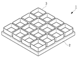
- the isogrid panel structure 1 includes an outer plate 2 and ribs 3 as shown in FIG.
- the outer plate 2 is formed as a flat plate formed from a carbon fiber reinforced resin containing carbon fibers.
- the rib 3 is joined to one surface of the outer plate 2.
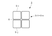
- the plurality of tubes 5-1 to 5-n are each formed of an aramid fiber reinforced resin including an aramid fiber and are congruent with each other.
- the plurality of tubes 5-1 to 5-n are arranged in a lattice pattern, that is, arranged so that the outer surface of the tube 5-i faces the outer surface of the other tube 5-j.
- the adhesive 6 is formed from a thermoplastic resin.
- the adhesive 6 is filled in a space sandwiched between the plurality of tubes 5-1 to 5-n, and bonds the plurality of tubes 5-1 to 5-n to each other.
- the plurality of tubes 5-1 to 5-n are arranged so that one end of the flow path formed inside the tube 5-i is closed by one surface of the outer plate 2. It is bonded to the outer plate 2 via an adhesive 6.
- the plurality of tubes 5-1 to 5-n are further joined to the outer plate 2 such that the direction of the flow path formed by each tube 5-i is perpendicular to the surface of the outer plate 2.
- the rib 3 is formed from a plurality of plate-like members respectively along a plurality of planes perpendicular to the surface of the outer plate 2.
- the isogrid panel structure 1 is formed in a so-called isogrid panel structure.
- the isogrid panel structure 1 is formed to have a predetermined bending rigidity so as to have a predetermined strength by joining the ribs 3 to the outer plate 2 in this way.
- the carbon fiber reinforced resin reinforced with carbon fibers has higher strength and higher bending rigidity than the aramid fiber reinforced resin reinforced with aramid fibers.
- the aramid fiber reinforced resin has higher vibration damping properties than the carbon fiber reinforced resin.
- the isogrid panel structure 1 has predetermined strength and bending rigidity, and has predetermined vibration damping properties.
- the isogrid panel structure 1 has a predetermined strength / bending rigidity and a predetermined vibration damping property, so that it is suitable for an outer panel of an aircraft fuselage and suitable for an outer panel of an aircraft wing. .
- the embodiment of the method for manufacturing the isogrid panel structure is a method for producing the isogrid panel structure 1.
- a tube 11 having a substantially square cross section is prepared.
- the tube 11 is formed from an aramid fiber reinforced resin reinforced with an aramid fiber and is manufactured by filament winding. That is, the tube 11 is produced by curing a resin impregnated in an aramid fiber wound around a side surface of a mold formed in a column.
- the tube 11 is cut into predetermined lengths and divided into a plurality of tubes 12-1 to 12-n that are congruent to each other (step S1).
- the outer plate 14 is further prepared, and the plurality of tubes 12-1 to 12-n are arranged such that one end of the flow path formed inside each tube 12-i is closed by one surface of the outer plate 14.
- the tubes 12-i are arranged in a lattice shape so that the outer surface of the tube 12-i faces the outer surface of the other tube 12-j (step S2).
- the plurality of tubes 12-1 to 12-n are formed congruent with each other, so that one surface of the outer plate 14 can be easily filled.
- a space between the outer surfaces of the plurality of tubes 12-1 to 12-n is filled with a thermoplastic resin
- a space between the plurality of tubes 12-1 to 12-n and the outer plate 14 is filled with a thermoplastic resin. Is done.
- the plurality of tubes 12-1 to 12-n and the outer plate 14 are heated in an assembled state.
- the thermoplastic resin is cured by heating the plurality of tubes 12-1 to 12-n and the outer plate 14, and bonds the plurality of tubes 12-1 to 12-n to each other. 1 to 12-n are bonded to the outer plate.
- the thermoplastic resin bonds the plurality of tubes 12-1 to 12-n to each other, and the thermoplastic resin is bonded to the plurality of tubes 12-1 to 12-n. Is bonded to the outer plate 14 to form the isogrid panel structure 1.
- the outer plate 2 corresponds to the outer plate 14, and the plurality of tubes 5-1 to 5-n correspond to the plurality of tubes 12-1 to 12-n.
- the adhesive 6 corresponds to a thermoplastic resin.
- the rib 3 is formed from a plurality of pipes 12-1 to 12-n, so that the isogrid panel structure is manufactured by integral molding.
- the isogrid panel structure 1 can be manufactured at a lower cost.
- FIG. 5 shows another embodiment of the isogrid panel structure.
- the isogrid panel structure 1 in the above-described embodiment further includes a plurality of reinforcing members 22.
- the plurality of reinforcing members 22 are made of carbon fiber and are formed in a string shape.
- the plurality of reinforcing members 22 are disposed along the plurality of parallel lines, respectively, and are disposed along the joint portions of the plurality of tubes 5-1 to 5-n.
- optional reinforcing members of the plurality of reinforcing members 22 are joined to the plurality of tubes 5-1 to 5-n via the adhesive 6.
- Such an isogrid panel structure 21 has a predetermined strength by joining the ribs 3 to the outer plate 2 and has the same strength as the isogrid panel structure 1 in the above-described embodiment. It has a bending rigidity of The isogrid panel structure 21 further includes a plurality of reinforcing members 22, thereby having a high tensile strength in the direction of a plurality of parallel lines along which the plurality of reinforcing members 22 are respectively aligned.
- the isogrid panel structure 21 When applied to an aircraft wing plate, the isogrid panel structure 21 is used such that the directions of a plurality of parallel lines along which the plurality of reinforcing members 22 are respectively arranged are substantially parallel to the wing length direction. The At this time, the isogrid panel structure 21 can give a predetermined bending rigidity in the wing length direction of the wing of the aircraft, and is suitable for the wing of the aircraft.
- the isogrid panel structure 21 has a plurality of tubes after the plurality of tubes 12-1 to 12-n and the outer plate 14 are assembled. It is manufactured by heating in a state where a plurality of reinforcing members 22 are arranged at the junctions 12-1 to 12-n. That is, the isogrid panel structure 21 can be produced at low cost in the same manner as the isogrid panel structure 1 in the above-described embodiment.
- FIG. 7 shows still another embodiment of the isogrid panel structure.
- the plurality of tubes 5-1 to 5-n of the isogrid panel structure 1 in the above-described embodiment are replaced with other plurality of tubes 32-1 to 32-n. Yes.
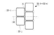
- the plurality of tubes 32-1 to 32-n are arranged in a staggered manner, that is, as shown in FIG. 8, the plurality of tubes 32-1 to 32-n are arranged outside one tube 32-i.
- the rib formed from the plurality of tubes 32-1 to 32-n is joined to the outer plate 2, so that the isogrid panel structure 1 in the above-described embodiment is provided.
- 21 has a predetermined strength and a predetermined bending rigidity.
- the isogrid panel structure 31 further includes a tube 32-i and a tube 32-j when a crack is formed in a portion of the adhesive 6 between the tubes 32-i and 32-j. Since the flat surface 33 along the joint surface overlaps the tube 32-k, the crack is difficult to progress. For this reason, the isogrid panel structure 31 has higher tensile strength in the direction perpendicular to the plane 33 than the isogrid panel structure 1 in the above-described embodiment.
- the isogrid panel structure 31 is joined to each other after the plurality of tubes 12-1 to 12-n and the outer plate 14 are assembled in the same manner as the isogrid panel structure 1 in the above-described embodiment. This is produced. That is, the isogrid panel structure 31 can be produced at low cost in the same manner as the isogrid panel structure 1 in the above-described embodiment.
- the isogrid panel structure 31 can further include a plurality of reinforcing members in the same manner as the isogrid panel structure 21 in the above-described embodiment.
- the plurality of reinforcing members are arranged along a plurality of parallel lines parallel to the direction perpendicular to the plane 33, and the plurality of tubes 32-1 are bonded by an adhesive that bonds the plurality of tubes 32-1 to 32-n to each other. Bonded to ⁇ 32-n.
- the isogrid panel structure has a higher tensile strength in a direction perpendicular to the plane 33.
- the plurality of tubes 5-1 to 5-n and 32-1 to 32-n can be replaced with other plurality of tubes formed in other quadrangles whose cross-section is different from the square.
- Examples of the quadrangle include a trapezoid and a parallelogram.
- a plurality of such tubes can be appropriately filled on the surface of the outer plate 2, and an isogrid panel structure to which such a plurality of tubes are applied has appropriate attributes (strength, bending rigidity, damping). ) And can be manufactured at low cost.
- the plurality of tubes 5-1 to 5-n can be replaced with other plurality of tubes having a cross-sectional shape different from a square. Examples of the shape include a triangle and a parallel hexagon.
- the plurality of tubes 32-1 to 32-n can be replaced by a plurality of tubes having a triangular cross section.
- a plurality of such tubes can be appropriately filled on the surface of the outer plate 2, and an isogrid panel structure to which such a plurality of tubes are applied has appropriate attributes (strength, bending rigidity, damping). ) And can be manufactured at low cost.
- the plurality of pipes 5-1 to 5-n can be joined sufficiently firmly to each other, it is not necessary to fill the gaps between the plurality of pipes 5-1 to 5-n with the adhesive 6 A space in which the adhesive 6 is not filled may be formed in the gaps between the plurality of tubes 5-1 to 5-n.
- the plurality of tubes 5-1 to 5-n do not need to be formed in a cross-sectional shape capable of filling a plane, and can be replaced with, for example, a plurality of tubes having a circular cross-sectional shape.
- the outer plate 2 can be replaced with an outer plate having a surface formed in a non-flat curved surface when the plurality of tubes 5-1 to 5-n can be sufficiently firmly joined to each other.
- the plurality of tubes 5-1 to 5-n are formed so that the thickness of the adhesive 6 between the plurality of tubes 5-1 to 5-n is not uniform, thereby filling a non-flat curved surface. Can be done.
- Such an isogrid panel structure can also be formed so as to have appropriate attributes (strength, bending rigidity, and damping), and can be manufactured at low cost.
- the plurality of tubes 5-1 to 5-n can include tubes having different sizes.
- the isogrid panel structure has a plurality of pipes having a small cross-sectional area disposed in a region having a large curvature on the surface of the outer plate 2, and a plurality of tubes having a large cross-sectional area disposed in a region having a small curvature.
- the gap between the tubes 5-1 to 5-n can be appropriately filled so as to be relatively small, and can be formed to have appropriate attributes (strength, bending rigidity, damping), low Can be made at cost.
- the tube 11 can be manufactured by a method different from filament winding.
- the method is exemplified by molding. That is, the tube 11 is made to impregnate the reinforcing fiber with resin by injecting the resin into the mold in which the reinforcing fibers are arranged, and resin into the reinforcing fiber by injecting the resin into the mold in which the reinforcing fibers are arranged. It is made by impregnating and curing the resin. Even when an isogrid panel structure is produced using a tube produced by molding, the isogrid panel structure is produced at a low cost in the same manner as the isogrid panel structure manufacturing method in the above-described embodiment. be able to.
- the plurality of tubes 12-1 to 12-n can be joined to each other without adding a thermoplastic resin.
- a method using a tube 11 formed from a semi-cured body is exemplified.
- the plurality of tubes 12-1 to 12-n are formed by cutting the tube 11 formed of a semi-cured body, and are arranged on the outer plate 14 so as to be in contact with each other. By being crimped, they are joined together and joined to the outer plate 14. Even when a plurality of tubes 12-1 to 12-n are joined in this way, the isogrid panel structure can be produced at a low cost in the same manner as the method for producing the isogrid panel structure in the embodiment described above. Can do.
- Isogrid panel structure 2 Outer plate 3: Ribs 5-1 to 5-n: Plural tubes 6: Adhesive 11: Tubes 12-1 to 12-n: Plural tubes 14: Outer plate 21: Iso Grid panel structure 22: Plural reinforcing members 31: Isogrid panel structure 32-1 to 32-n: Plural tubes 33: Plane
Landscapes
- Engineering & Computer Science (AREA)
- Architecture (AREA)
- Civil Engineering (AREA)
- Structural Engineering (AREA)
- Mechanical Engineering (AREA)
- Moulding By Coating Moulds (AREA)
- Laminated Bodies (AREA)
Abstract
外板がリブにより補強されることにより形成されるアイソグリッドパネル構造体を低コストで作製する。管(11)を複数の管(12-1~12-n)に切断すること(ステップS1)、外板(14)を補強するリブが複数の管(12-1~12-n)から形成されるように、複数の管(12-1~12-n)を外板(14)に接合すること(ステップS2)と、を備えている。このようなアイソグリッドパネル構造体製造方法よれば、外板(14)を補強するリブを複数の管(12-1~12-n)から形成することにより、外板(14)がリブにより補強されることにより形成されるアイソグリッドパネル構造体を低コストで作製することができる。
Description
本発明は、アイソグリッドパネル構造体およびアイソグリッドパネル構造体製造方法に関し、特に、繊維強化樹脂から形成されるアイソグリッドパネル構造体およびアイソグリッドパネル構造体製造方法に関する。
航空機やロケット等の製品は、軽量であることが要求され、外板を薄くすることが望まれ、外板に炭素繊維強化樹脂(CFRP、Carbon-Fiber-Reinforced Plastic)に例示される複合材を適用することが望まれている(特許文献1参照。)。
航空機やロケット等の製品の外板は、さらに、座屈を防止する必要がある。座屈を防止する構造として、外板に格子状の小骨(リブ)が設けられたアイソグリッド構造が知られている。炭素繊維強化樹脂を用いて形成されたアイソグリッドパネル構造体は、金属を用いて形成されたアイソグリッドパネル構造体に比較して、成形にコストを要する。繊維強化樹脂から形成されるアイソグリッドパネル構造体を低コストで作製することが望まれている。
本発明の課題は、低コストで作製されるアイソグリッドパネル構造体およびアイソグリッドパネル構造体製造方法を提供することにある。
本発明の第1の態様にかかるアイソグリッドパネル構造体は、繊維強化樹脂から形成される複数の管が互いに接合されることにより形成されるリブと、繊維強化樹脂から形成される外板とを備えている。このとき、前記リブは、前記複数の管の各々の一端が前記外板により塞がれるように、前記外板に接合される。
このようなアイソグリッドパネル構造体は、外板を補強するリブが複数の管から形成されることにより、容易に作製されることができる。
このようなアイソグリッドパネル構造体は、外板を補強するリブが複数の管から形成されることにより、容易に作製されることができる。
前記第1の態様にかかるアイソグリッドパネル構造体は、前記複数の管を互いに接着する接着剤をさらに備えていてもよい。
このようなアイソグリッドパネル構造体は、接着剤を用いて複数の管が互いに接着されることにより、外板を補強するリブが容易に作製されることができ、容易に作製されることができる。
このようなアイソグリッドパネル構造体は、接着剤を用いて複数の管が互いに接着されることにより、外板を補強するリブが容易に作製されることができ、容易に作製されることができる。
前記第1の態様にかかるアイソグリッドパネル構造体は、前記複数の管が接合される接合領域に沿って配置される強化部材をさらに備えていてもよい。
このようなアイソグリッドパネル構造体は、強化部材が沿う直線の方向の曲げ剛性を向上させることができる。
このようなアイソグリッドパネル構造体は、強化部材が沿う直線の方向の曲げ剛性を向上させることができる。
前記複数の管が形成される材料は、前記外板が形成される材料と異なっていてもよい。
このようなアイソグリッドパネル構造体は、リブと外板とが異なる材料から形成されることにより、リブと外板とが同一の材料から形成される他のアイソグリッドパネル構造体に比較して、適切な属性(強度・曲げ剛性・減衰性)を有するように形成されることができる。
このようなアイソグリッドパネル構造体は、リブと外板とが異なる材料から形成されることにより、リブと外板とが同一の材料から形成される他のアイソグリッドパネル構造体に比較して、適切な属性(強度・曲げ剛性・減衰性)を有するように形成されることができる。
前記複数の管は、アラミド系繊維を含むアラミド系繊維強化樹脂から形成され、前記外板は、炭素繊維を含む炭素繊維強化樹脂から形成されていてもよい。
このようなアイソグリッドパネル構造体は、航空機の翼に好適である属性(強度・曲げ剛性・減衰性)を有している。
このようなアイソグリッドパネル構造体は、航空機の翼に好適である属性(強度・曲げ剛性・減衰性)を有している。
前記複数の管は、前記複数の管のうちの隣り合う2つの管が接合される接合面に沿う平面が、前記複数の管のうちの前記2つの管と異なる他の管に重なるように、配置されていてもよい。
前記複数の管は、複数の小管と、複数の大管とを含んでいる。このとき、前記複数の大管のうちの任意の大管の断面積は、前記複数の小管のうちの任意の小管の断面積より大きくてもよい。
このようなアイソグリッドパネル構造体は、リブを形成する複数の管が複数の小管と複数の大管とを含むことにより、外板が平坦でない場合でも、外板に複数の管を適切に敷き詰めることができ、適切な属性を有するように低コストで作製されることができる。
このようなアイソグリッドパネル構造体は、リブを形成する複数の管が複数の小管と複数の大管とを含むことにより、外板が平坦でない場合でも、外板に複数の管を適切に敷き詰めることができ、適切な属性を有するように低コストで作製されることができる。
本発明の第2の態様にかかる航空機は、本発明によるアイソグリッドパネル構造体から形成される翼を備えている。このとき、前記強化部材は、前記翼の翼長方向に平行である直線に沿って配置されている。
このような航空機は、翼の翼長方向の引張強度が高く、好ましい。
このような航空機は、翼の翼長方向の引張強度が高く、好ましい。
本発明の第3の態様にかかるアイソグリッドパネル構造体製造方法は、管を複数の管に切断することと、外板を補強するリブが前記複数の管から形成されるように、前記複数の管を前記外板に接合することと、を備えている。
このようなアイソグリッドパネル構造体製造方法よれば、外板を補強するリブを複数の管から形成することにより、外板がリブにより補強されることにより形成されるアイソグリッドパネル構造体を低コストで作製することができる。
このようなアイソグリッドパネル構造体製造方法よれば、外板を補強するリブを複数の管から形成することにより、外板がリブにより補強されることにより形成されるアイソグリッドパネル構造体を低コストで作製することができる。
前記第3の態様にかかるアイソグリッドパネル構造体製造方法は、フィラメントワインディングにより前記管を作製することをさらに備えていてもよい。
フィラメントワインディングにより作製された管は、モールディングにより作製する管に比較して、位置による強度のむらが少ない。このため、このようなアイソグリッドパネル構造体製造方法よれば、複数の管が一様の強度を有するように作製することができ、強度が適切であるアイソグリッドパネル構造体を低コストで作製することができる。
フィラメントワインディングにより作製された管は、モールディングにより作製する管に比較して、位置による強度のむらが少ない。このため、このようなアイソグリッドパネル構造体製造方法よれば、複数の管が一様の強度を有するように作製することができ、強度が適切であるアイソグリッドパネル構造体を低コストで作製することができる。
前記管は、繊維に樹脂が含浸された半硬化体から形成されている。このとき、前記複数の管は、加熱されることにより、互いに接合されてもよい。
このようなアイソグリッドパネル構造体製造方法によれば、別途に接着剤を利用することなく、外板がリブにより補強されることにより形成されるアイソグリッドパネル構造体を低コストで作製することができる。
このようなアイソグリッドパネル構造体製造方法によれば、別途に接着剤を利用することなく、外板がリブにより補強されることにより形成されるアイソグリッドパネル構造体を低コストで作製することができる。
本発明によるアイソグリッドパネル構造体およびアイソグリッドパネル構造体製造方法は、外板を補強するリブが複数の管から形成されることにより、製造コストを低減することができる。
図面を参照して、アイソグリッドパネル構造体の実施の形態が以下に記載される。そのアイソグリッドパネル構造体1は、図1に示されているように、外板2とリブ3とを備えている。外板2は、炭素繊維を含む炭素繊維強化樹脂から形成される平坦な板に形成されている。リブ3は、外板2の一方の面に接合されている。
リブ3は、図2に示されるように、複数の管5-1~5-n(n=2,3,4,…)と接着剤6とを備えている。複数の管5-1~5-nは、それぞれ、アラミド系繊維を含むアラミド系繊維強化樹脂から形成され、互いに合同である。複数の管5-1~5-nの任意の管5-i(i=1,2,3,…,n)は、断面形状が概ね正方形である管状に形成され、概ね平坦である4つの外側面が形成されている。複数の管5-1~5-nは、格子状に配置され、すなわち、管5-iの外側面が他の管5-jの外側面に対向するように、配置されている。
接着剤6は、熱可塑性樹脂から形成されている。接着剤6は、複数の管5-1~5-nの間に挟まれた空間に充填され、複数の管5-1~5-nを互いに接着している。
複数の管5-1~5-nは、さらに、図3に示されるように、管5-iの内部に形成された流路の一端が外板2の一方の面により閉鎖されるように、接着剤6を介して外板2に接着されている。複数の管5-1~5-nは、さらに、各管5-iにより形成される流路の方向が外板2の表面に垂直になるように、外板2に接合されている。このため、リブ3は、外板2の表面に垂直である複数の平面にそれぞれ沿う複数の板状部材から形成される。その結果、アイソグリッドパネル構造体1は、所謂アイソグリッドパネル構造に形成される。
アイソグリッドパネル構造体1は、このように外板2にリブ3が接合されることにより、所定の強度を有するように、所定の曲げ剛性を有するように形成される。炭素繊維で強化された炭素繊維強化樹脂は、アラミド系繊維で強化されたアラミド系繊維強化樹脂に比較して、強度がより高く、曲げ剛性がより高い。アラミド系繊維強化樹脂は、炭素繊維強化樹脂に比較して、振動減衰性がより高い。このため、アイソグリッドパネル構造体1は、所定の強度・曲げ剛性を有し、所定の振動減衰性を有している。アイソグリッドパネル構造体1は、所定の強度・曲げ剛性と所定の振動減衰性とを有していることにより、航空機の胴体の外板に好適であり、航空機の翼の外板に好適である。
アイソグリッドパネル構造体製造方法の実施の形態は、アイソグリッドパネル構造体1を作製する方法である。アイソグリッドパネル構造体製造方法では、図4に示されるように、まず、断面が概ね正方形である管11が準備される。管11は、アラミド系繊維で強化されたアラミド系繊維強化樹脂から形成され、フィラメントワインディングにより作製される。すなわち、管11は、柱体に形成された型の側面に巻き付けられたアラミド系繊維に含浸させた樹脂を硬化させることにより作製される。管11は、所定の長さごとに切断され、互いに合同である複数の管12-1~12-nに分割される(ステップS1)。
外板14がさらに準備され、複数の管12-1~12-nは、各管12-iの内部に形成された流路の一端が外板14の一方の面により閉鎖されるように、かつ、管12-iの外側面が他の管12-jの外側面に対向するように格子状に、配置される(ステップS2)。このとき、複数の管12-1~12-nは、互いに合同に形成されていることにより、外板14の一方の面に容易に充填することができる。複数の管12-1~12-nの外側面の間には、熱可塑性樹脂が充填され、複数の管12-1~12-nと外板14との間にも、熱可塑性樹脂が充填される。
複数の管12-1~12-nと外板14とは、組み立てられた状態で、加熱される。熱可塑性樹脂は、複数の管12-1~12-nと外板14とが加熱されることにより、硬化し、複数の管12-1~12-nを互いに接着させ、複数の管12-1~12-nを外板14に接着させる。複数の管12-1~12-nと外板14とは、熱可塑性樹脂が複数の管12-1~12-nを互いに接着し、熱可塑性樹脂が複数の管12-1~12-nを外板14に接着することにより、アイソグリッドパネル構造体1に形成される。すなわち、このように作製されたアイソグリッドパネル構造体1は、外板2が外板14に対応し、複数の管5-1~5-nが複数の管12-1~12-nに対応し、接着剤6が熱可塑性樹脂に対応している。
このようなアイソグリッドパネル構造体製造方法によれば、複数の管12-1~12-nからリブ3を形成することにより、アイソグリッドパネル構造体を一体成形により作製する他の製造方法に比較して、アイソグリッドパネル構造体1をより低コストで作製することができる。
図5は、アイソグリッドパネル構造体の実施の他の形態を示している。そのアイソグリッドパネル構造体21は、既述の実施の形態におけるアイソグリッドパネル構造体1がさらに複数の強化部材22を備えている。複数の強化部材22は、炭素繊維から形成され、紐状に形成されている。複数の強化部材22は、複数の平行線にそれぞれ沿うように配置され、複数の管5-1~5-nの接合部に沿って配置されている。複数の強化部材22の任意の強化部材は、図6に示されているように、接着剤6を介して複数の管5-1~5-nに接合されている。
このようなアイソグリッドパネル構造体21は、外板2にリブ3が接合されることにより、既述の実施の形態におけるアイソグリッドパネル構造体1と同様にして、所定の強度を有し、所定の曲げ剛性を有している。アイソグリッドパネル構造体21は、さらに、複数の強化部材22を備えることにより、複数の強化部材22がそれぞれ沿う複数の平行線の方向に高い引っ張り強度を有する。
アイソグリッドパネル構造体21は、航空機の翼の板に適用されるときに、複数の強化部材22がそれぞれ沿う複数の平行線の方向が翼長方向に概ね平行に配置されるように、利用される。このとき、アイソグリッドパネル構造体21は、航空機の翼の翼長方向に所定の曲げ剛性を与えることができ、航空機の翼に好適である。
アイソグリッドパネル構造体21は、既述の実施の形態におけるアイソグリッドパネル構造体1と同様にして、複数の管12-1~12-nと外板14とが組み立てられた後に、複数の管12-1~12-nの接合部に複数の強化部材22が配置された状態で、加熱されることにより、作製される。すなわち、アイソグリッドパネル構造体21は、既述の実施の形態におけるアイソグリッドパネル構造体1と同様にして、低コストで作成されることができる。
図7は、アイソグリッドパネル構造体の実施のさらに他の形態を示している。そのアイソグリッドパネル構造体31は、既述の実施の形態におけるアイソグリッドパネル構造体1の複数の管5-1~5-nが他の複数の管32-1~32-nに置換されている。複数の管32-1~32-nは、千鳥状に配置され、すなわち、図8に示されているように、複数の管32-1~32-nは、管32-iの1つの外側面と管32-jの1つの外側面とが重なるように接合されているときに、管32-iと管32-jとの接合面に沿う平面33が管32-k(k≠i、かつ、k≠j、かつ、k=1,2,3,…,n)と交差するように、配置されている。
このようなアイソグリッドパネル構造体31は、複数の管32-1~32-nから形成されるリブが外板2に接合されることにより、既述の実施の形態におけるアイソグリッドパネル構造体1、21と同様にして、所定の強度を有し、所定の曲げ剛性を有している。アイソグリッドパネル構造体31は、さらに、接着剤6のうちの管32-iと管32-jとの間の部分に亀裂が形成されたときに、管32-iと管32-jとの接合面に沿う平面33が管32-kと重なっていることにより、その亀裂が進展しにくい。このため、アイソグリッドパネル構造体31は、既述の実施の形態におけるアイソグリッドパネル構造体1に比較して、平面33と垂直な方向の引っ張り強度がより高い。
アイソグリッドパネル構造体31は、既述の実施の形態におけるアイソグリッドパネル構造体1と同様にして、複数の管12-1~12-nと外板14とが組み立てられた後に互いに接合されることにより、作製される。すなわち、アイソグリッドパネル構造体31は、既述の実施の形態におけるアイソグリッドパネル構造体1と同様にして、低コストで作成されることができる。
アイソグリッドパネル構造体31は、さらに、既述の実施の形態におけるアイソグリッドパネル構造体21と同様にして、複数の強化部材を備えることができる。その複数の強化部材は、平面33と垂直な方向に平行である複数の平行線に沿って配置され、複数の管32-1~32-nを互いに接着する接着剤により複数の管32-1~32-nに接着される。アイソグリッドパネル構造体は、平面33と垂直な方向の引っ張り強度がさらに高い。
複数の管5-1~5-n、32-1~32-nは、断面が正方形と異なる他の四角形に形成される他の複数の管に置換されることができる。その四角形としては、台形、平行四辺形が例示される。このような複数の管も、外板2の表面に適切に充填されることができ、このような複数の管が適用されるアイソグリッドパネル構造体は、適切な属性(強度・曲げ剛性・減衰性)を有するように形成され、低コストで作製されることができる。
さらに、複数の管5-1~5-nは、断面が四角形と異なる形状に形成される他の複数の管にも置換されることができる。その形状としては、三角形、平行六角形が例示される。複数の管32-1~32-nに関しては、断面が三角形に形成される複数の管にも置換されることができる。このような複数の管も、外板2の表面に適切に充填されることができ、このような複数の管が適用されるアイソグリッドパネル構造体は、適切な属性(強度・曲げ剛性・減衰性)を有するように形成され、低コストで作製されることができる。
さらに、複数の管5-1~5-nは、互いに十分に強固に接合されることができるときに、複数の管5-1~5-nの隙間を接着剤6で充填する必要がなく、複数の管5-1~5-nの隙間に接着剤6が充填されない空間が形成されてもよい。このとき、複数の管5-1~5-nは、平面を充填可能な形状に断面が形成される必要がなく、たとえば、断面形状が円である複数の管に置換されることもできる。
外板2は、複数の管5-1~5-nが互いに十分に強固に接合されることができるときに、平坦でない曲面に形成された表面を有する外板に置換されることができる。たとえば、複数の管5-1~5-nは、複数の管5-1~5-nの間の接着剤6の厚さが一様でないように形成されることにより、平坦でない曲面に充填されることができる。このようなアイソグリッドパネル構造体も、適切な属性(強度・曲げ剛性・減衰性)を有するように形成されることができ、低コストで作製されることができる。
複数の管5-1~5-nは、大きさが異なる管を含むこともできる。このとき、アイソグリッドパネル構造体は、外板2の表面のうちの曲率が大きい領域に断面積が小さい管を配置し、曲率が小さい領域に断面積が大きい管を配置することにより、複数の管5-1~5-nの隙間が比較的小さくなるように、適切に充填することができ、適切な属性(強度・曲げ剛性・減衰性)を有するように形成されることができ、低コストで作製されることができる。
なお、管11は、フィラメントワインディングと異なる方法で作製されることができる。その方法としては、モールディングが例示される。すなわち、管11は、強化繊維が配置された型の内部に樹脂を注入することにより強化繊維に樹脂を含浸させ、強化繊維が配置された型の内部に樹脂を注入することにより強化繊維に樹脂を含浸させ、その樹脂を硬化させることにより作製される。モールディングにより作製された管を用いてアイソグリッドパネル構造体を作製した場合も、既述の実施の形態におけるアイソグリッドパネル構造体製造方法と同様にして、アイソグリッドパネル構造体を低コストで作製することができる。
複数の管12-1~12-nは、熱可塑性樹脂を添加しないで互いに接合されることもできる。その方法としては、半硬化体から形成された管11を用いる方法が例示される。このとき、複数の管12-1~12-nは、半硬化体から形成された管11が切断されることにより形成され、互いに接触するように外板14上に配置された状態で、熱圧着されることにより、互いに接合され、外板14に接合される。複数の管12-1~12-nをこのように接合した場合でも、既述の実施の形態におけるアイソグリッドパネル構造体製造方法と同様にして、アイソグリッドパネル構造体を低コストで作製することができる。
1 :アイソグリッドパネル構造体
2 :外板
3 :リブ
5-1~5-n:複数の管
6 :接着剤
11:管
12-1~12-n:複数の管
14:外板
21:アイソグリッドパネル構造体
22:複数の強化部材
31:アイソグリッドパネル構造体
32-1~32-n:複数の管
33:平面
2 :外板
3 :リブ
5-1~5-n:複数の管
6 :接着剤
11:管
12-1~12-n:複数の管
14:外板
21:アイソグリッドパネル構造体
22:複数の強化部材
31:アイソグリッドパネル構造体
32-1~32-n:複数の管
33:平面
Claims (11)
- 繊維強化樹脂から形成される複数の管が互いに接合されることにより形成されるリブと、
繊維強化樹脂から形成される外板と、を備え、
前記リブは、前記複数の管の各々の一端が前記外板により塞がれるように、前記外板に接合されるアイソグリッドパネル構造体。 - 前記複数の管を互いに接着する接着剤をさらに備える請求項1に記載されるアイソグリッドパネル構造体。
- 前記複数の管が接合される接合領域に沿って配置される強化部材をさらに備える請求項1~請求項2のうちのいずれか一項に記載されるアイソグリッドパネル構造体。
- 前記複数の管が形成される材料は、前記外板が形成される材料と異なる請求項1~請求項3のうちのいずれか一項に記載されるアイソグリッドパネル構造体。
- 前記複数の管は、アラミド系繊維を含むアラミド系繊維強化樹脂から形成され、
前記外板は、炭素繊維を含む炭素繊維強化樹脂から形成される請求項4に記載されるアイソグリッドパネル構造体。 - 前記複数の管は、前記複数の管のうちの隣り合う2つの管が接合される接合面に沿う平面が、前記複数の管のうちの前記2つの管と異なる他の管に重なるように、配置される請求項1~請求項5のうちのいずれか一項に記載されるアイソグリッドパネル構造体。
- 前記複数の管は、
複数の小管と、
複数の大管と、を含み、
前記複数の大管のうちの任意の大管の断面積は、前記複数の小管のうちの任意の小管の断面積より大きい請求項1~請求項5のうちのいずれか一項に記載されるアイソグリッドパネル構造体。 - 請求項3に記載されるアイソグリッドパネル構造体から形成される翼を備え、
前記強化部材は、前記翼の翼長方向に平行である直線に沿って配置される航空機。 - 管を複数の管に切断することと、
外板を補強するリブが前記複数の管から形成されるように、前記複数の管を前記外板に接合することと、
を備えるアイソグリッドパネル構造体製造方法。 - フィラメントワインディングにより前記管を作製することをさらに備える請求項9に記載されるアイソグリッドパネル構造体製造方法。
- 前記管は、繊維に樹脂が含浸された半硬化体から形成され、
前記複数の管は、加熱されることにより、互いに接合される請求項9~請求項10のうちのいずれか一項に記載されるアイソグリッドパネル構造体製造方法。
Applications Claiming Priority (2)
| Application Number | Priority Date | Filing Date | Title |
|---|---|---|---|
| JP2013-273198 | 2013-12-27 | ||
| JP2013273198A JP2015127121A (ja) | 2013-12-27 | 2013-12-27 | アイソグリッドパネル構造体およびアイソグリッドパネル構造体製造方法 |
Publications (1)
| Publication Number | Publication Date |
|---|---|
| WO2015098147A1 true WO2015098147A1 (ja) | 2015-07-02 |
Family
ID=53478039
Family Applications (1)
| Application Number | Title | Priority Date | Filing Date |
|---|---|---|---|
| PCT/JP2014/065082 Ceased WO2015098147A1 (ja) | 2013-12-27 | 2014-06-06 | アイソグリッドパネル構造体およびアイソグリッドパネル構造体製造方法 |
Country Status (2)
| Country | Link |
|---|---|
| JP (1) | JP2015127121A (ja) |
| WO (1) | WO2015098147A1 (ja) |
Families Citing this family (2)
| Publication number | Priority date | Publication date | Assignee | Title |
|---|---|---|---|---|
| JP6367997B1 (ja) * | 2017-03-14 | 2018-08-01 | 新明和工業株式会社 | グリッド補強構造体の製造方法、及び、グリッド補強構造体 |
| JP6989321B2 (ja) | 2017-08-29 | 2022-01-05 | 三菱重工業株式会社 | 飛翔体 |
Citations (4)
| Publication number | Priority date | Publication date | Assignee | Title |
|---|---|---|---|---|
| JPS63188438A (ja) * | 1987-01-30 | 1988-08-04 | Showa Aircraft Ind Co Ltd | ハニカム材 |
| JPH091681A (ja) * | 1995-06-21 | 1997-01-07 | Fuji Heavy Ind Ltd | 繊維強化複合材の構造体及びその製造方法 |
| JPH11216782A (ja) * | 1998-02-02 | 1999-08-10 | Sakura Rubber Co Ltd | リブ構造体の製造方法 |
| JP2004009453A (ja) * | 2002-06-05 | 2004-01-15 | Mitsubishi Electric Corp | グリッド構造およびその作製方法 |
-
2013
- 2013-12-27 JP JP2013273198A patent/JP2015127121A/ja active Pending
-
2014
- 2014-06-06 WO PCT/JP2014/065082 patent/WO2015098147A1/ja not_active Ceased
Patent Citations (4)
| Publication number | Priority date | Publication date | Assignee | Title |
|---|---|---|---|---|
| JPS63188438A (ja) * | 1987-01-30 | 1988-08-04 | Showa Aircraft Ind Co Ltd | ハニカム材 |
| JPH091681A (ja) * | 1995-06-21 | 1997-01-07 | Fuji Heavy Ind Ltd | 繊維強化複合材の構造体及びその製造方法 |
| JPH11216782A (ja) * | 1998-02-02 | 1999-08-10 | Sakura Rubber Co Ltd | リブ構造体の製造方法 |
| JP2004009453A (ja) * | 2002-06-05 | 2004-01-15 | Mitsubishi Electric Corp | グリッド構造およびその作製方法 |
Also Published As
| Publication number | Publication date |
|---|---|
| JP2015127121A (ja) | 2015-07-09 |
Similar Documents
| Publication | Publication Date | Title |
|---|---|---|
| JP6177611B2 (ja) | 相互薄板状の金属シートで補強された積層複合材の屈曲および補強部材 | |
| CN102026798B (zh) | 增强的硬化构件及其制造方法 | |
| CN104023954B9 (zh) | 具有共结合的加强件的复合材料柱状结构及制造方法 | |
| EP2666622B1 (en) | Skin-stiffener transition assembly, method of manufacture and application of said skin-stiffener transition assembly | |
| KR101837217B1 (ko) | 일체화된 보강부재를 갖는 복합 구조물 그 제조 방법 | |
| JP6719495B2 (ja) | プリフォーム賦形方法、複合材成形方法及び複合材 | |
| US20130020438A1 (en) | Flexible Truss Frame and Method of Making the Same | |
| JP2011042170A (ja) | 繊維強化プラスチック構造体及び繊維強化プラスチック構造体の製造方法 | |
| JP5920471B2 (ja) | 三次元繊維強化複合材及び三次元繊維強化複合材の製造方法 | |
| US9931809B2 (en) | Composite material structure and method of manufacturing composite material structure | |
| JP7195451B2 (ja) | 複合材料リブ成形および複合材料リブアンドシート成形のための方法および装置 | |
| JP6238168B2 (ja) | 複合材構造 | |
| JP5972854B2 (ja) | 繊維強化複合部材の接合方法及び接合体、並びに風車翼の製造方法 | |
| JP2017119432A (ja) | 繊維強化プラスチックの製造方法および繊維強化プラスチック | |
| JP6103239B2 (ja) | 補強梁材 | |
| TW201819163A (zh) | 片材以及棒狀構件 | |
| JP2015127121A (ja) | アイソグリッドパネル構造体およびアイソグリッドパネル構造体製造方法 | |
| JP4928403B2 (ja) | サンドイッチパネルの剥離進展防止構造 | |
| CA2987171C (en) | Honeycomb core sandwich panels | |
| WO2020003608A1 (ja) | 複合材、複合材の製造方法、及び複合材の硬化方法 | |
| JP7183350B1 (ja) | 複合材構造体及び複合材構造体の製造方法 | |
| US11685503B2 (en) | Stringer assemblies and methods of forming thereof | |
| KR20180068223A (ko) | 섬유 강화 열가소성 타입 테이프의 제조 방법, 및 섬유 강화 열가소성 타입 테이프 |
Legal Events
| Date | Code | Title | Description |
|---|---|---|---|
| 121 | Ep: the epo has been informed by wipo that ep was designated in this application |
Ref document number: 14875255 Country of ref document: EP Kind code of ref document: A1 |
|
| NENP | Non-entry into the national phase |
Ref country code: DE |
|
| 122 | Ep: pct application non-entry in european phase |
Ref document number: 14875255 Country of ref document: EP Kind code of ref document: A1 |