WO2015093189A1 - 車両制御装置 - Google Patents
車両制御装置 Download PDFInfo
- Publication number
- WO2015093189A1 WO2015093189A1 PCT/JP2014/079981 JP2014079981W WO2015093189A1 WO 2015093189 A1 WO2015093189 A1 WO 2015093189A1 JP 2014079981 W JP2014079981 W JP 2014079981W WO 2015093189 A1 WO2015093189 A1 WO 2015093189A1
- Authority
- WO
- WIPO (PCT)
- Prior art keywords
- vehicle
- idling stop
- stop control
- road gradient
- distance
- Prior art date
- Legal status (The legal status is an assumption and is not a legal conclusion. Google has not performed a legal analysis and makes no representation as to the accuracy of the status listed.)
- Ceased
Links
Images


Classifications
-
- F—MECHANICAL ENGINEERING; LIGHTING; HEATING; WEAPONS; BLASTING
- F02—COMBUSTION ENGINES; HOT-GAS OR COMBUSTION-PRODUCT ENGINE PLANTS
- F02N—STARTING OF COMBUSTION ENGINES; STARTING AIDS FOR SUCH ENGINES, NOT OTHERWISE PROVIDED FOR
- F02N11/00—Starting of engines by means of electric motors
- F02N11/08—Circuits specially adapted for starting of engines
- F02N11/0814—Circuits specially adapted for starting of engines comprising means for controlling automatic idle-start-stop
- F02N11/0818—Conditions for starting or stopping the engine or for deactivating the idle-start-stop mode
- F02N11/0833—Vehicle conditions
- F02N11/0837—Environmental conditions thereof, e.g. traffic, weather or road conditions
-
- B—PERFORMING OPERATIONS; TRANSPORTING
- B60—VEHICLES IN GENERAL
- B60W—CONJOINT CONTROL OF VEHICLE SUB-UNITS OF DIFFERENT TYPE OR DIFFERENT FUNCTION; CONTROL SYSTEMS SPECIALLY ADAPTED FOR HYBRID VEHICLES; ROAD VEHICLE DRIVE CONTROL SYSTEMS FOR PURPOSES NOT RELATED TO THE CONTROL OF A PARTICULAR SUB-UNIT
- B60W30/00—Purposes of road vehicle drive control systems not related to the control of a particular sub-unit, e.g. of systems using conjoint control of vehicle sub-units
- B60W30/06—Automatic manoeuvring for parking
-
- B—PERFORMING OPERATIONS; TRANSPORTING
- B60—VEHICLES IN GENERAL
- B60W—CONJOINT CONTROL OF VEHICLE SUB-UNITS OF DIFFERENT TYPE OR DIFFERENT FUNCTION; CONTROL SYSTEMS SPECIALLY ADAPTED FOR HYBRID VEHICLES; ROAD VEHICLE DRIVE CONTROL SYSTEMS FOR PURPOSES NOT RELATED TO THE CONTROL OF A PARTICULAR SUB-UNIT
- B60W30/00—Purposes of road vehicle drive control systems not related to the control of a particular sub-unit, e.g. of systems using conjoint control of vehicle sub-units
- B60W30/08—Active safety systems predicting or avoiding probable or impending collision or attempting to minimise its consequences
- B60W30/09—Taking automatic action to avoid collision, e.g. braking and steering
-
- F—MECHANICAL ENGINEERING; LIGHTING; HEATING; WEAPONS; BLASTING
- F02—COMBUSTION ENGINES; HOT-GAS OR COMBUSTION-PRODUCT ENGINE PLANTS
- F02D—CONTROLLING COMBUSTION ENGINES
- F02D45/00—Electrical control not provided for in groups F02D41/00 - F02D43/00
-
- G—PHYSICS
- G08—SIGNALLING
- G08G—TRAFFIC CONTROL SYSTEMS
- G08G1/00—Traffic control systems for road vehicles
- G08G1/16—Anti-collision systems
- G08G1/166—Anti-collision systems for active traffic, e.g. moving vehicles, pedestrians, bikes
-
- B—PERFORMING OPERATIONS; TRANSPORTING
- B60—VEHICLES IN GENERAL
- B60W—CONJOINT CONTROL OF VEHICLE SUB-UNITS OF DIFFERENT TYPE OR DIFFERENT FUNCTION; CONTROL SYSTEMS SPECIALLY ADAPTED FOR HYBRID VEHICLES; ROAD VEHICLE DRIVE CONTROL SYSTEMS FOR PURPOSES NOT RELATED TO THE CONTROL OF A PARTICULAR SUB-UNIT
- B60W2552/00—Input parameters relating to infrastructure
- B60W2552/15—Road slope, i.e. the inclination of a road segment in the longitudinal direction
-
- B—PERFORMING OPERATIONS; TRANSPORTING
- B60—VEHICLES IN GENERAL
- B60W—CONJOINT CONTROL OF VEHICLE SUB-UNITS OF DIFFERENT TYPE OR DIFFERENT FUNCTION; CONTROL SYSTEMS SPECIALLY ADAPTED FOR HYBRID VEHICLES; ROAD VEHICLE DRIVE CONTROL SYSTEMS FOR PURPOSES NOT RELATED TO THE CONTROL OF A PARTICULAR SUB-UNIT
- B60W2554/00—Input parameters relating to objects
-
- B—PERFORMING OPERATIONS; TRANSPORTING
- B60—VEHICLES IN GENERAL
- B60W—CONJOINT CONTROL OF VEHICLE SUB-UNITS OF DIFFERENT TYPE OR DIFFERENT FUNCTION; CONTROL SYSTEMS SPECIALLY ADAPTED FOR HYBRID VEHICLES; ROAD VEHICLE DRIVE CONTROL SYSTEMS FOR PURPOSES NOT RELATED TO THE CONTROL OF A PARTICULAR SUB-UNIT
- B60W2554/00—Input parameters relating to objects
- B60W2554/80—Spatial relation or speed relative to objects
- B60W2554/802—Longitudinal distance
-
- F—MECHANICAL ENGINEERING; LIGHTING; HEATING; WEAPONS; BLASTING
- F02—COMBUSTION ENGINES; HOT-GAS OR COMBUSTION-PRODUCT ENGINE PLANTS
- F02N—STARTING OF COMBUSTION ENGINES; STARTING AIDS FOR SUCH ENGINES, NOT OTHERWISE PROVIDED FOR
- F02N2200/00—Parameters used for control of starting apparatus
- F02N2200/12—Parameters used for control of starting apparatus said parameters being related to the vehicle exterior
- F02N2200/124—Information about road conditions, e.g. road inclination or surface
-
- F—MECHANICAL ENGINEERING; LIGHTING; HEATING; WEAPONS; BLASTING
- F02—COMBUSTION ENGINES; HOT-GAS OR COMBUSTION-PRODUCT ENGINE PLANTS
- F02N—STARTING OF COMBUSTION ENGINES; STARTING AIDS FOR SUCH ENGINES, NOT OTHERWISE PROVIDED FOR
- F02N2200/00—Parameters used for control of starting apparatus
- F02N2200/12—Parameters used for control of starting apparatus said parameters being related to the vehicle exterior
- F02N2200/125—Information about other vehicles, traffic lights or traffic congestion
-
- Y—GENERAL TAGGING OF NEW TECHNOLOGICAL DEVELOPMENTS; GENERAL TAGGING OF CROSS-SECTIONAL TECHNOLOGIES SPANNING OVER SEVERAL SECTIONS OF THE IPC; TECHNICAL SUBJECTS COVERED BY FORMER USPC CROSS-REFERENCE ART COLLECTIONS [XRACs] AND DIGESTS
- Y02—TECHNOLOGIES OR APPLICATIONS FOR MITIGATION OR ADAPTATION AGAINST CLIMATE CHANGE
- Y02T—CLIMATE CHANGE MITIGATION TECHNOLOGIES RELATED TO TRANSPORTATION
- Y02T10/00—Road transport of goods or passengers
- Y02T10/10—Internal combustion engine [ICE] based vehicles
- Y02T10/40—Engine management systems
Definitions
- the present disclosure relates to a vehicle control device.
- a vehicle control apparatus that stops and restarts a vehicle engine, and determines whether or not the vehicle will slide down after stopping when traveling on a hill with the engine stopped.
- a control device that permits the start of engine restart so that the engine restart is completed before the vehicle slip distance exceeds the allowable distance when it is determined that a drop occurs (for example, a patent) Reference 1).
- the vehicle may slip down when the engine is restarted in the idling stop control. Therefore, it is useful to consider the state of obstacles behind the vehicle.
- an object of the present disclosure is to provide a vehicle control device that can execute idling stop control in a manner that considers an obstacle behind the vehicle.
- a rear obstacle distance information acquisition unit that acquires information about a distance between an obstacle behind the vehicle and the vehicle (hereinafter referred to as a rear obstacle distance);
- Road gradient information acquisition means for acquiring information about the road gradient at the current position of the vehicle;
- a control device that permits idling stop control when the obstacle processing and the road gradient satisfy a predetermined relationship under a situation where the vehicle speed is equal to or lower than a predetermined vehicle speed;
- the vehicle control device is set such that the predetermined front-rear relationship is set to be less likely to be satisfied as the road gradient increases on an uphill road, and less likely to be satisfied as the rear obstacle distance decreases.
- a vehicle control device that can execute idling stop control in a manner that considers obstacles behind the vehicle.
- FIG. 1 is a system configuration diagram of a control system according to an embodiment.
- the control system 1 includes an idling stop control ECU (Electronic Control Unit) 10, a pre-crash ECU 20, an airbag ECU 30, and an engine ECU 32.
- the connection state of each element (a sensor etc. are included) in FIG. 1 is arbitrary.
- the connection mode may be connection via a bus such as CAN (controller area network), indirect connection via other ECUs, or direct connection.
- a connection mode capable of wireless communication may be used.
- the division of the functions of these ECUs is arbitrary, and some or all of the functions of a specific ECU may be realized by other ECUs (including ECUs not shown).
- part or all of the idling stop control ECU 10 may be realized by the engine ECU 32.
- the idling stop control ECU 10 is connected with a wheel speed sensor 44, a user preference selection switch (SW) 50, a starter motor 60 for starting the engine, and the like.
- the user preference selection switch 50 is an interface for the user to input a preference for fuel consumption, and may be provided at any place in the vehicle interior.
- the user preference selection switch 50 may be in the form of a touch switch.
- the user preference selection switch 50 is a switch in which a mode for canceling idling stop control (idling stop cancel mode) is set by a short press operation, and a fuel consumption priority mode is set by a long press operation.
- the modes include a default normal mode, an idling stop cancel mode, and a fuel efficiency priority mode.
- a rear laser sensor 22 is connected to the pre-crash ECU 20.
- the rear radar sensor 22 detects the presence and state of a rear vehicle (typically a following vehicle) behind the vehicle using radio waves (for example, millimeter waves), light waves (for example, lasers), or ultrasonic waves as detection waves. To do.
- the rear radar sensor 22 detects information indicating a relationship between the rear vehicle, for example, a relative speed, a relative distance, and an azimuth (lateral position) of the rear vehicle with reference to the vehicle at a predetermined cycle.
- the millimeter wave radar sensor 22 When the rear radar sensor 22 is a millimeter wave radar sensor, the millimeter wave radar sensor may be, for example, an electronic scan type millimeter wave radar, and in this case, using the Doppler frequency (frequency shift) of the radio wave, The relative speed is detected, the relative distance of the rear vehicle is detected using the delay time of the reflected wave, and the direction of the rear vehicle is detected based on the phase difference between the receptions of the plurality of receiving antennas.
- the pre-crash ECU 20 Based on the information from the rear laser sensor 22, performs pre-crash control for preventing a collision or reducing damage at the time of the collision.
- the content of the pre-crash control is arbitrary, but is typically automatic control.
- the pre-crash ECU 20 may perform only the rear obstacle notification instead of the pre-crash control.
- the pre-crash ECU 20 has another name (clearance sonar ECU).
- the rear radar sensor 22 may include, for example, both a millimeter wave radar sensor for pre-crash control and an ultrasonic sensor for rear obstacle notification.
- the pre-crash ECU 20 may be connected to the millimeter wave radar sensor for pre-crash control
- the clearance sonar ECU may be connected to the ultrasonic sensor.
- the idling stop control ECU 10 may use information from the two rear radar sensors 22 (rear vehicle distance information described later).
- an image sensor may be used instead of or in addition to the rear radar sensor 22.
- the image sensor includes a camera and an image processing apparatus including an image sensor such as a charge-coupled device (CCD) and a complementary metal (oxide) semiconductor (CMOS), and recognizes the state of the rear vehicle.
- the camera of the image sensor may be a stereo camera or may include two or more cameras in another manner. Based on the image recognition result, the image sensor detects information indicating the relationship between the rear vehicle and the host vehicle, for example, the speed and position information of the rear vehicle based on the host vehicle at a predetermined cycle.
- the position information of the rear vehicle may include information regarding the position (distance) of the rear vehicle in the front-rear direction of the host vehicle and information regarding the lateral position of the rear vehicle in the lateral direction (width direction).
- the idling stop control ECU 10 acquires information on the rear vehicle (particularly information on the distance to the rear vehicle, hereinafter referred to as “rear vehicle distance information”) via the pre-crash ECU 20.
- the idling stop control ECU 10 may directly acquire the rear vehicle distance information from the rear radar sensor 22.
- the yaw rate / acceleration sensor 40 is connected to the airbag ECU 30.
- the yaw rate / acceleration sensor 40 may be a triaxial acceleration sensor.
- the yaw rate / acceleration sensor 40 is provided near the position of the center of gravity of the vehicle (floor tunnel or the like), and detects the yaw rate and acceleration generated at the mounting position.
- the yaw rate / acceleration sensor 40 may be replaced with a sensor that detects only acceleration.
- the idling stop control ECU 10 acquires detection information (tilt information) of the yaw rate / acceleration sensor 40 via the airbag ECU 30. Note that the idling stop control ECU 10 may directly acquire the tilt information from the yaw rate / acceleration sensor 40. The idling stop control ECU 10 detects a road gradient (inclination in the pitch direction) based on the inclination information of the yaw rate / acceleration sensor 40.
- the idling stop control ECU 10 determines whether or not a predetermined idling stop control start condition is satisfied. When it is determined that the predetermined idling stop control start condition is satisfied, the engine is stopped and the idling stop control is started. . Further, the idling stop control ECU 10 determines whether or not a predetermined idling stop control end condition is satisfied during the idling stop control, and determines that the predetermined idling stop control end condition is satisfied, and then restarts the engine. Start and end idling stop control.
- the predetermined idling stop control start condition is arbitrary, but typically includes that the vehicle speed is equal to or lower than the predetermined vehicle speed.
- the predetermined vehicle speed is typically zero.
- the predetermined vehicle speed may be greater than 0 and may be a lower limit value of the vehicle speed at which idling stop control is possible. That is, the idling stop control may be performed even when the vehicle is decelerating in a low vehicle speed region other than when the vehicle is stopped.
- the predetermined idling stop control start condition may include, for example, a condition regarding an air conditioning state, a battery state, or the like.
- the predetermined idling stop control termination condition is arbitrary, but typically may include conditions relating to the state of the brake pedal, the air conditioning state (decrease in air conditioning comfort), the battery state (decrease in charge amount), and the like.
- the predetermined idling stop control start condition and / or the predetermined idling stop control end condition includes a condition related to a road gradient (hereinafter referred to as “road gradient condition”).
- the road gradient condition relating to the predetermined idling stop control start condition and the predetermined idling stop control end condition may be a relationship between the other predetermined conditions and the AND condition.
- the rational gradient condition related to the predetermined idling stop control termination condition may be in an OR condition relationship with other conditions.
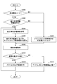
- FIG. 2 is a flowchart showing an example of processing executed by the idling stop control ECU 10.
- the processing routine shown in FIG. 2 is started when the idling stop control start condition other than the road gradient condition is satisfied under the condition that is not in the idling stop cancel mode, and even when the idling stop control is repeated at predetermined intervals. Good. Needless to say, the processing routine shown in FIG. 2 may be integrated with a processing routine for determining an idling stop control start condition other than the road gradient condition.
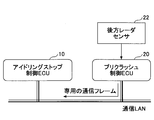
- FIG. 3 is an explanatory diagram of the process (step 202) for determining the possibility of acquiring the rear vehicle distance information.
- step 200 it is determined whether or not the fuel economy priority mode is set based on the setting information by the user preference selection switch 50. If it is in the fuel efficiency priority mode, the process proceeds to step 202, and otherwise (in the normal mode), the process proceeds to step 208.
- step 202 it is determined whether or not the rear vehicle distance information can be acquired. Whether or not the rear vehicle distance information can be acquired is determined by monitoring the communication LAN (local-area network) such as CAN (controller network area) as shown in FIG. It is good to do.
- LAN local-area network
- CAN controller network area
- the pre-crash ECU 20 is mounted, a dedicated communication frame flows in the communication LAN section. Therefore, whether or not the pre-crash ECU 20 is mounted may be determined based on the presence or absence of the communication frame. For example, when it is detected three times that a dedicated communication frame is flowing, it may be determined that the pre-crash ECU 20 is mounted, that is, the rear vehicle distance information can be acquired.
- this type of determination takes into consideration that some vehicles are equipped with a pre-crash system or the like as an option, and some vehicles are not. Therefore, such a determination is unnecessary for a vehicle type in which the pre-crash system is always mounted. If the rear vehicle distance information can be acquired, the process proceeds to step 204. Otherwise, the process proceeds to step 208.
- step 204 the latest rear vehicle distance information is acquired.
- the rear vehicle distance information may be acquired in synchronization with the processing cycle of this processing routine.
- an idle stop allowable inclination Y corresponding to the rear vehicle distance X is calculated based on the rear vehicle distance information.
- the idle stop allowable inclination Y is calculated in a predetermined range (hereinafter referred to as “allowable inclination variable range”) in such a manner that it becomes smaller (the inclination becomes gentler) as the rear vehicle distance X becomes smaller.
- This variable mode may be two or more stages.
- the idle stop allowable inclination Y is set to a predetermined value Y1.
- the predetermined value Y1 is an arbitrary value smaller than the maximum value in the allowable inclination variable range, but is typically the minimum value in the allowable inclination variable range.
- step 210 the latest inclination information is acquired.
- the tilt information may be acquired in synchronization with the processing cycle of this processing routine.
- step 212 it is determined whether or not the road gradient based on the latest inclination information acquired in step 210 is less than the idle stop allowable inclination Y set in step 206 or step 208. If the road gradient is less than the idle stop allowable inclination Y, the process proceeds to step 214; otherwise, the process proceeds to step 216.
- step 214 idling stop control is permitted. Thereby, idling stop control is started or the state in idling stop control is continued. That is, in the first processing routine, the engine is stopped and idling stop control is started. In the second and subsequent processing routines, the idling stop control is continued. When the process of step 214 is completed, the process returns to step 204, and the process from step 204 is executed in the next processing cycle.
- step 216 idling stop control is prohibited. As a result, the idling stop control is prohibited or the idling stop control is terminated. That is, in the first processing routine, the idling stop control is prohibited (the engine is not stopped). In the second and subsequent processing routines, the idling stop control is terminated and the engine is restarted. In the second and subsequent processing routines, as a scene in which the determination result in step 212 is affirmative, typically, after the affirmative determination in step 212, a situation change has occurred in which the rear vehicle packs up the space between vehicles. Is the case. When the processing of step 216 is completed, the processing routine for the current idling stop control period ends.
- the idle stop allowable inclination Y is varied according to the rear inter-vehicle distance X. That is, the idle stop allowable inclination Y is varied in such a manner that it becomes smaller as the rear vehicle distance X becomes smaller.
- idling stop control can be performed in the aspect which considered the back vehicle distance.
- the rear vehicle distance is relatively long, a relatively large idle stop allowable inclination is used, so that idling stop control is promoted and fuel consumption can be improved.
- the rear vehicle distance is relatively short, since a relatively small idle stop allowable inclination is used, idling stop control is suppressed, and safety can be improved.
- the idle stop allowable inclination Y is varied according to the rear vehicle distance X with respect to the road gradient condition related to the idling stop control start condition (step 206, nest tap 212). And step 214).
- idling stop control can be started in the aspect which considered the back vehicle distance.
- the rear vehicle distance is relatively long (even when there is no rear vehicle)
- the rear vehicle distance is long even when a slip occurs due to the release of the brake pedal at the end of the idling stop control. It is possible to secure the necessary distance from the vehicle behind the vehicle. Therefore, in such a case, the idling stop control is easily started with priority on fuel consumption.
- idling stop control is permitted even when the road gradient is relatively large.
- the rear vehicle distance is relatively short, it becomes difficult to secure a necessary distance from the rear vehicle when a slip-down occurs at the end of the idling stop control. Therefore, in such a case, it is difficult to start the idling stop control with priority given to safety. That is, idling stop control is permitted only when the road gradient is relatively small. In this way, the idling stop control can be executed in a manner that achieves both fuel efficiency and safety.
- the road gradient condition related to the idling stop control end condition is determined (monitored), and the road gradient condition related to the idling stop control end condition is also determined for the rear vehicle.
- the idle stop allowable inclination is varied according to the distance (see step 206, step 212, and step 216).
- idling stop control can be complete
- the determination result in step 212 is often an affirmative determination in the subsequent processing cycle. This is because the rear vehicle distance and the road gradient at the time when an affirmative determination is made in step 212 basically does not change during the idling stop control.
- the rear vehicle distance changes when a rear vehicle that has not been detected until the previous cycle is detected during the idling stop control, or when the rear vehicle closes up.
- the determination process of step 204 to step 212 is repeatedly executed during the idling stop control. Therefore, the idling stop control can be stopped when a situation change occurs and the rear vehicle distance is shortened during the idling stop control.
- the processing shown in FIG. 2 is preferably applied to a vehicle that does not perform vehicle stabilization control that stabilizes the behavior of the vehicle by preventing a side slip of the vehicle on a curved road or the like.
- the process shown in FIG. 2 may be unnecessary for a vehicle including a solenoid valve that can maintain the wheel cylinder pressure with the brake pedal being turned off. This is because in such a vehicle, by holding the wheel cylinder pressure at the end of the idling stop control, it is possible to prevent the vehicle from slipping down at the end of the idling stop control.
- the process shown in FIG. 2 may be executed for such a vehicle. In this case, for example, the idle stop allowable inclination may be set higher than that of a vehicle that does not include a solenoid valve that holds the wheel cylinder pressure.
- FIG. 4 is a diagram showing an example of the relationship between the idle stop allowable inclination Y and the rear vehicle distance X that may be used in Step 206 and Step 208 of FIG.
- the physical quantity of the idle stop allowable inclination Y is a road gradient [°], which indicates an upward gradient angle.
- the allowable tilt variable range is 2 to 6 [°].
- the idle stop allowable inclination Y is set to 2 [°] as the predetermined value Y1.
- the idle stop allowable inclination Y is set to 2 [°] as the predetermined value Y2.
- the idle stop allowable inclination Y is set to 4 [°] as the predetermined values Y3 and Y4.
- the idle stop allowable inclination Y is set to 6 [°] as Y5.
- the idle stop allowable inclination Y may be a value interpolated according to the rear vehicle distance, for example, 3 [° ] May be set. Similarly, when the rear vehicle distance is larger than 1.25 and smaller than 1.5, an interpolated value may be used as the idle stop allowable inclination Y, for example, 5 [°] is set. Also good. In addition, when a following vehicle is not detected (however, step 202 of FIG. 2 is affirmation determination), it is good to treat that the back vehicle distance is infinity. In this case, the idle stop allowable inclination Y is set to 6 [°] which is the maximum value.
- the idle stop allowable inclination Y when the rear vehicle distance is 0.5 [m] or less is set to a predetermined value Y1 used when a negative determination is made in step 200 or step 204.
- the idle stop allowable inclination Y may be smaller than a predetermined value Y1, or may be zero in the end.
- the idling stop allowable inclination Y being 0 means that idling stop control is substantially prohibited.
- numerical values such as 0.5 [m] and 2 [°] are examples, and various changes can be made.
- the idle stop allowable inclination is changed in three steps (2 [°], 4 [°], 6 [°]) according to the rear vehicle distance. Alternatively, it may be changed in four steps or more.
- the idle stop allowable inclination has a first value when the rear vehicle distance is larger than the predetermined distance, and a second value ( ⁇ (First value).
- the second value may be the same as the predetermined value Y1 used when a negative determination is made in step 200 or 204, but may be smaller than the predetermined value Y1, or ultimately 0. May be.
- the two-stage variable aspect of the idle stop allowable inclination is particularly suitable when the rear radar sensor 22 is an ultrasonic sensor.
- the idle stop allowable inclination Y is set to the first value when the rear vehicle is not detected by the ultrasonic sensor (that is, when the rear vehicle distance is longer than the detection distance), and the rear vehicle is detected by the ultrasonic sensor. May be set to the second value (i.e., when the rear vehicle distance is shorter than the detection distance).
- the two-stage change mode also corresponds to a “mode that is difficult to be satisfied as the rear vehicle distance becomes shorter”.
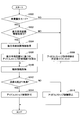
- FIG. 5 is a flowchart showing a modification of the process shown in FIG.
- the process shown in FIG. 5 is started when an idling stop control start condition other than the road gradient condition is satisfied in a situation that is not in the idling stop cancel mode, and when the road gradient condition related to the idling stop control start condition is determined. It is executed only once.
- Steps 500, 502, 504, 506, 508, 510, and 512 in FIG. 5 are the same as steps 200, 202, 204, 206, 208, and 210 shown in FIG.
- Step 212 may be the same as each processing.
- step 514 idling step control is permitted. Thereby, idling stop control is started.
- the processing routine for the present idling stop control opportunity is completed.
- step 516 idling stop control is prohibited. Thereby, idling stop control is prohibited.
- the processing routine for the present idling stop control opportunity ends.
- the idle stop allowable inclination Y is varied according to the rear vehicle distance X for the road gradient condition related to the idling stop control start condition.
- idling stop control can be started in the aspect which considered the back vehicle distance.
- the idling stop control end condition may not include the road gradient condition.
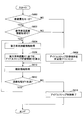
- FIG. 6 is a flowchart showing another modification of the process shown in FIG.
- the process shown in FIG. 6 may be repeatedly executed at predetermined intervals during idling stop control.
- Step 600, step 602, step 604, step 606, step 608, step 610, and step 612 in FIG. 6 are the same as step 200, step 202, step 204, step 206, step 208, and step 210 shown in FIG.
- Step 212 may be the same as each processing.
- step 612 If an affirmative determination is made in step 612, the processing returns to step 604, and the processing from step 604 is executed in the next processing cycle.
- step 616 the idling stop control ends. Thereby, idling stop control is complete
- the processing routine for the current idling stop control opportunity ends.
- the idling stop control when a rear vehicle appears during the idling stop control or when the rear vehicle distance is shortened, the idling stop control can be terminated as necessary to improve safety. . That is, if a rear vehicle appears during the idling stop control or the rear vehicle distance decreases (when the rear vehicle distance becomes shorter than when the idling stop control starts), the idling stop control is terminated as necessary. Therefore, safety can be improved.
- the idling stop control start condition may not include the road gradient condition.
- the idling stop control start condition may include a road gradient condition that does not consider the rear vehicle distance. That is, the idling stop allowable inclination may be constant regardless of the rear vehicle distance.
- the rear vehicle distance information is detected by the rear radar sensor 22, but the rear vehicle distance information may be acquired by inter-vehicle communication with the rear vehicle.
- the tilt information is acquired from the yaw rate / acceleration sensor 40, but may be acquired from a navigation device (not shown). This is because road gradient information may be included in the map data used in the navigation device. In this case, the idling stop control ECU 10 may acquire road gradient information corresponding to the vehicle position from the navigation device.
- the default normal mode, the idling stop cancel mode, and the fuel consumption priority mode exist.
- only the normal mode and the idling stop cancel mode may be provided, or only one mode may be used. (That is, a specification that cannot cancel the idling stop control).
- the airbag ECU 30 and the pre-crash ECU 20 are provided, but the airbag ECU 30 and / or the pre-crash ECU 20 may be omitted.
- the rear radar sensor 22 may be directly connected to the idling stop control ECU 10, may be connected via another ECU, or is connected via a communication LAN or the like. May be.
- the rear vehicle is considered, but an obstacle other than the vehicle (rear obstacle) may be considered in the same manner.
- the rear obstacle may be, for example, a pedestrian.
- the lateral position of the rear vehicle is not considered, but the lateral position of the rear vehicle may be considered.
- the lateral position of the rear vehicle may be considered.
- only the rear vehicle on the traveling lane of the own vehicle may be considered based on the lateral position of the rear vehicle.
- the road gradient is set as a threshold value (idle stop allowable inclination), and the idle stop allowable inclination is varied according to the rear vehicle distance.
- the rear vehicle distance is set as a threshold value (idle stop allowable rear vehicle distance).
- the idle stop allowable rear vehicle distance may be varied according to the road gradient. In this case, the idle stop allowable rear vehicle distance is varied in such a manner that it becomes shorter as the road gradient increases.
- the road gradient is set as a threshold value (idle stop allowable inclination), and the idle stop allowable inclination is varied in accordance with the rear vehicle distance. You may compare with the threshold value. For example, idling stop control may be permitted when the road gradient is smaller than a predetermined gradient and the rear vehicle distance is longer than a predetermined distance. Similarly, during the idling stop control, the idling stop control may be prohibited and / or terminated when the road gradient is larger than the predetermined gradient and the rear vehicle distance is shorter than the predetermined distance.
- idling stop control may be permitted when the road gradient is smaller than a predetermined gradient and the rear vehicle distance is longer than a predetermined distance.
- the idling stop control may be prohibited and / or terminated when the road gradient is larger than the predetermined gradient and the rear vehicle distance is shorter than the predetermined distance.
- Controllability system 10 Idling stop control ECU 22 Rear radar sensor 40 Yaw rate / acceleration sensor
Landscapes
- Engineering & Computer Science (AREA)
- Mechanical Engineering (AREA)
- General Engineering & Computer Science (AREA)
- Combustion & Propulsion (AREA)
- Chemical & Material Sciences (AREA)
- Transportation (AREA)
- Health & Medical Sciences (AREA)
- Life Sciences & Earth Sciences (AREA)
- Atmospheric Sciences (AREA)
- Environmental & Geological Engineering (AREA)
- Toxicology (AREA)
- Automation & Control Theory (AREA)
- Physics & Mathematics (AREA)
- General Physics & Mathematics (AREA)
- Control Of Vehicle Engines Or Engines For Specific Uses (AREA)
- Combined Controls Of Internal Combustion Engines (AREA)
- Traffic Control Systems (AREA)
Abstract
車両後方の障害物と車両との距離(以下、後方障害物距離という)に関する情報を取得する後方障害物距離情報取得手段と、 車両の現在位置における道路勾配に関する情報を取得する道路勾配情報取得手段と、 車速が所定車速以下である状況下で、前記後方障害物距離及び前記道路勾配が所定関係を満たす場合に、アイドリングストップを許可する制御装置とを備え、 前記所定関係は、上り勾配の道路における前記道路勾配が大きくなるにつれて満たされ難くなり、且つ、前記後方障害物距離が短くなるにつれて満たされ難くなるように、設定される、車両制御装置。
Description
本開示は、車両制御装置に関する。
従来から、車両のエンジンを停止及び再始動させる車両の制御装置であって、エンジンが停止された状態での坂路走行時に、停車後の車両のずり下がりが発生するか否かを判定し、ずり下がりが発生すると判定されたときには、車両のずり下がり距離が許容距離を超えるまでにエンジンの再始動が完了するようにエンジンの再始動の開始を許可する制御装置が知られている(例えば、特許文献1参照)。
ところで、登坂路においては道路勾配によってはアイドリングストップ制御におけるエンジン再始動時に車両のずり下がりが発生しうるため、車両後方の障害物の状況を考慮することが有用である。
そこで、本開示は、車両後方の障害物を考慮した態様でアイドリングストップ制御を実行することができる車両制御装置の提供を目的とする。
本開示の一局面によれば、車両後方の障害物と車両との距離(以下、後方障害物距離という)に関する情報を取得する後方障害物距離情報取得手段と、
車両の現在位置における道路勾配に関する情報を取得する道路勾配情報取得手段と、
車速が所定車速以下である状況下で、前記攻防障害物処理及び前記道路勾配が所定関係を満たす場合に、アイドリングストップ制御を許可する制御装置とを備え、
前後所定関係は、上り勾配の道路における前記道路勾配が大きくなるにつれて満たされ難くなり、且つ、前記後方障害物距離が短くなるにつてれ満たされ難くなるように、設定される、車両制御装置が提供される。
車両の現在位置における道路勾配に関する情報を取得する道路勾配情報取得手段と、
車速が所定車速以下である状況下で、前記攻防障害物処理及び前記道路勾配が所定関係を満たす場合に、アイドリングストップ制御を許可する制御装置とを備え、
前後所定関係は、上り勾配の道路における前記道路勾配が大きくなるにつれて満たされ難くなり、且つ、前記後方障害物距離が短くなるにつてれ満たされ難くなるように、設定される、車両制御装置が提供される。
本開示によれば、車両後方の障害物を考慮した態様でアイドリングストップ制御を実行することができる車両制御装置が得られる。
以下、添付図面を参照しながら各実施例について詳細に説明する。
図1は、一実施例による制御系のシステム構成図である。制御系システム1は、アイドリングストップ制御ECU(Electronic Control Unit)10と、プリクラッシュECU20と、エアバッグECU30と、エンジンECU32とを含む。尚、図1における各要素(センサ等を含む)の接続様態は、任意である。例えば、接続態様は、CAN(controller area network)などのバスを介した接続であってもよいし、他のECU等を介した間接的な接続であってもよいし、直接的な接続であってもよいし、無線通信可能な接続態様であってもよい。尚、これらのECUの機能の区分けは、任意であり、特定のECUの機能の一部又は全部は、他のECU(図示されていないECUを含む)により実現されてもよい。例えば、アイドリングストップ制御ECU10の一部又は全部は、エンジンECU32により実現されてもよい。
アイドリングストップ制御ECU10には、車輪速センサ44、ユーザ嗜好選択スイッチ(SW)50、エンジン始動のためのスタータモータ60等が接続される。ユーザ嗜好選択スイッチ50は、燃費に対する嗜好をユーザが入力するためのインターフェースであり、車室内の任意の場所に設けられてよい。ユーザ嗜好選択スイッチ50は、タッチスイッチの形態であってもよい。ここでは、一例として、ユーザ嗜好選択スイッチ50は、短押し操作で、アイドリングストップ制御をキャンセルするモード(アイドリングストップキャンセルモード)が設定され、長押し操作で、燃費優先モードが設定されるスイッチであるとする。尚、ここでは、一例として、モードは、デフォルトの通常モードと、アイドリングストップキャンセルモードと、燃費優先モードとが存在する。
プリクラッシュECU20には、後方レーザセンサ22が接続される。後方レーダセンサ22は、電波(例えばミリ波)、光波(例えばレーザ)又は超音波を検出波として用いて、車両後方における後方車両(典型的には、後続車両)の存在及び、その状態を検出する。後方レーダセンサ22は、後方車両と車両との関係を示す情報、例えば車両を基準とした後方車両の相対速度や相対距離、方位(横位置)を所定の周期で検出する。尚、後方レーダセンサ22がミリ波レーダセンサの場合、ミリ波レーダセンサは、例えば電子スキャン型のミリ波レーダであってよく、この場合、電波のドップラー周波数(周波数シフト)を用いて後方車両の相対速度が検出され、反射波の遅れ時間を用いて後方車両の相対距離が検出され、複数の受信アンテナ間での受信はの位相差に基づいて後方車両の方位が検出される。プリクラッシュECU20は、後方レーザセンサ22からの情報に基づいて、衝突を防止するための又は衝突時の被害を軽減するためのプリクラッシュ制御を実行する。プリクラッシュ制御の内容は任意であるが、典型的には、自動制御である。
尚、後方レーダセンサ22が超音波を用いるセンサ(超音波センサ)である場合、プリクラッシュECU20は、プリクラッシュ制御に代えて、後方障害物報知のみを行うこととしてもよい。この場合、プリクラッシュECU20は、他の名称(クリアランスソナーECU)となる。或いは、後方レーダセンサ22は、例えば、プリクラッシュ制御用のミリ波レーダーセンサと、後方障害物報知用の超音波センサの双方を含んでもよい。この場合、プリクラッシュ制御用のミリ波レーダーセンサには、プリクラッシュECU20が接続され、超音波センサには、クリアランスソナーECUが接続されてよい。この場合、アイドリングストップ制御ECU10は、2つの後方レーダセンサ22からの情報(後述の後方車両距離情報)を用いることとしてもよい。
また、後方レーダセンサ22に代えて又はそれに加えて、画像センサが使用されてもよい。画像センサは、CCD(charge-coupled device)やCMOS(complementary metal oxide semiconductor)等の撮像素子を含むカメラ及び画像処理装置を含み、後方車両の状態を画像認識する。画像センサのカメラは、ステレオカメラであってもよいし、他の態様で2つ以上のカメラを含んでもよい。画像センサは、画像認識結果に基づいて、後方車両と自車との関係を示す情報、例えば自車を基準とした後方車両の速度や位置情報を所定の周期で検出する。後方車両の位置情報は、自車前後方向における後方車両の位置(距離)に関する情報、及び、横方向(幅方向)における後方車両の横位置に関する情報を含んでよい。
アイドリングストップ制御ECU10は、プリクラッシュECU20を介して、後方車両の情報(特に後方車両との距離に関する情報であり、以下、「後方車両距離情報」という)を取得する。尚、アイドリングストップ制御ECU10は、後方レーダセンサ22から後方車両距離情報を直接取得してもよい。
エアバッグECU30には、ヨーレート/加速度センサ40が接続される。ヨーレート/加速度センサ40は、3軸の加速度センサであってよい。例えば、ヨーレート/加速度センサ40は、車両の重心位置付近(フロアトンネル等)に設けられ、当該搭載位置に発生するヨーレート及び加速度を検出する。ヨーレート/加速度センサ40は、加速度のみを検出するセンサに置換されてもよい。
アイドリングストップ制御ECU10は、エアバッグECU30を介して、ヨーレート/加速度センサ40の検出情報(傾斜情報)を取得する。尚、アイドリングストップ制御ECU10は、ヨーレート/加速度センサ40から傾斜情報を直接取得してもよい。アイドリングストップ制御ECU10は、ヨーレート/加速度センサ40の傾斜情報に基づいて、道路勾配(ピッチ方向の傾斜)を検出する。
アイドリングストップ制御ECU10は、所定のアイドリングストップ制御開始条件が成立したか否かを判定し、所定のアイドリングストップ制御開始条件が成立したと判定した場合に、エンジンを停止してアイドリングストップ制御を開始する。また、アイドリングストップ制御ECU10は、アイドリングストップ制御中は、所定のアイドリングストップ制御終了条件が成立したが否かを判定し、所定のアイドリングストップ制御終了条件が成立したと判定した場合に、エンジンを再始動してアイドリングストップ制御を終了する。
所定のアイドリングストップ制御開始条件は、任意であるが、典型的には、車速が所定車速以下であることを含む。所定車速は、典型的には、0である。但し、所定車速は、0よりも大きく、アイドリングストップ制御が可能な車速の下限値であってもよい。即ち、停止時以外の低車速領域における減速時等においてもアイドリングストップ制御を行う構成であってもよい。また、所定のアイドリングストップ制御開始条件は、例えば、空調状態やバッテリ状態等に関する条件を含んでよい。所定のアイドリングストップ制御終了条件は、任意であるが、典型的には、ブレーキペダルの状態や空調状態(空調快適性の低下)やバッテリ状態(充電量の低下)等に関する条件を含んでよい。
本実施例では、以下で説明するように、所定のアイドリングストップ制御開始条件及び/又は所定のアイドリングストップ制御終了条件は、道路勾配に関する条件(以下、「道路勾配条件」という)を含む。所定のアイドリングストップ制御開始条件及び所定のアイドリングストップ制御終了条件に係る道路勾配条件は、他の所定の条件とAND条件の関係であってよい。但し、所定のアイドリングストップ制御終了条件に係る道理勾配条件は、他の条件とはOR条件の関係であってもよい。
図2は、アイドリングストップ制御ECU10により実行される処理の一例を示すフローチャートである。図2に示す処理ルーチンは、アイドリングストップキャンセルモードではない状況下で、道路勾配条件以外のアイドリングストップ制御開始条件が成立した場合に起動され、アイドリングストップ制御中、所定周期毎に繰り返し時刻されてもよい。尚、当然ながら、図2に示す処理ルーチンは、道路勾配条件以外のアイドリングストップ制御開始条件を判断する処理ルーチンに統合されてもよい。図3は、後方車両距離情報の取得の可能性を判断する処理(ステップ202)の説明図である。
ステップ200では、ユーザ嗜好選択スイッチ50による設定情報に基づいて、燃費優先モードであるか否かを判定する。燃費優先モードである場合は、ステップ202に進み、それ以外の場合(通常モードの場合)、ステップ208に進む。
ステップ202では、後方車両距離情報を取得可能であるか否かを判定する。後方車両距離情報を取得可能であるか否かは、例えば、図3に示すように、CAN(controller area network)などの通信LAN(local-area network)を監視し、プリクラッシュECU20の有無を判定することとしてもよい。プリクラッシュECU20が搭載されている場合には、通信LAN条に専用の通信フレームが流れるため、かかる通信フレームの有無に基づいて、プリクラッシュECU20が搭載されているか否かを判定してもよい。例えば、専用の通信フレームが流れていることを3回検出した場合には、プリクラッシュECU20が搭載されている、即ち後方車両距離情報を取得可能であると判定してもよい。尚、この種の判定は、プリクラッシュシステムなどがオプションにより搭載される車両と搭載されない車両があることを考慮したものである。従って、常にプリクラッシュシステムが搭載される車種では、かかる判定は不要である。後方車両距離情報を取得可能である場合は、ステップ204に進み、それ以外の場合は、ステップ208に進む。
ステップ204では、最新の後方車両距離情報を取得する。尚、後方車両距離情報は、本処理ルーチンの処理周期に同期されて取得されてよい。
ステップ206では、後方車両距離情報に基づいて、後方車両距離Xに応じたアイドルストップ許容傾斜Yを算出する。アイドルストップ許容傾斜Yは、所定範囲(以下、「許容傾斜可変範囲」という)内で、後方車両距離Xが小さくなるほど小さくなる(傾斜が緩くなる)態様で算出される。この可変態様は、2段階以上あればよい。
ステップ208では、アイドルストップ許容傾斜Yを所定値Y1に設定する。所定値Y1は、許容傾斜可変範囲内の最大値よりも小さい任意の値であるが、典型的には、許容傾斜可変範囲内の最小値である。
ステップ210では、最新の傾斜情報を取得する。尚、傾斜情報は、本処理ルーチンの処理周期に同期されて取得されてよい。
ステップ212では、上記ステップ210で取得した最新の傾斜情報に基づく道路勾配が、上記ステップ206又はステップ208で設定したアイドルストップ許容傾斜Y未満であるか否かを判定する。道路勾配がアイドルストップ許容傾斜Y未満である場合には、ステップ214に進み、それ以外の場合には、ステップ216に進む。
ステップ214では、アイドリングストップ制御を許可する。これにより、アイドリングストップ制御が開始され又はアイドリングストップ制御中の状態が継続される。即ち、初回の処理ルーチンでは、エンジンを停止させ、アイドリングストップ制御を開始する。また、2回目以後の処理ルーチンでは、アイドリングストップ制御を継続する。ステップ214の処理が終了すると、ステップ204に戻り、次の処理周期にてステップ204からの処理を実行する。
ステップ216では、アイドリングストップ制御を禁止する。これにより、アイドリングストップ制御が禁止され又はアイドリングストップ制御が終了される、即ち、初回の処理ルーチンでは、アイドリングストップ制御を禁止する(エンジンの停止が実行されない)。また、2回目以降の処理ルーチンでは、アイドリングストップ制御を終了し、エンジンを再始動する。尚、2回目以後の処理ルーチンでステップ212の判定結果が肯定判定となる場面としては、典型的には、ステップ212の肯定判定後に、後方車両が車間を詰めてくるような状況変化が生じた場合である。ステップ216の処理が終了すると、今回のアイドリングストップ制御期間に対する処理ルーチンは終了となる。
図2に示す処理によれば、後方車間距離Xに応じてアイドルストップ許容傾斜Yが可変される。即ち、アイドルストップ許容傾斜Yは、後方車両距離Xか小さくなるほど小さくなる態様で可変される。これにより、後方車両距離を考慮した態様でアイドリングストップ制御を実行することができる。具体的には、後方車両距離が比較的長い場合は、比較的大きなアイドルストップ許容傾斜が用いられるので、アイドリングストップ制御が促進され、燃費向上を図ることができる。他方、後方車両距離が比較的短い場合は、比較的小さいアイドルストップ許容傾斜が用いられるので、アイドリングストップ制御が抑制され、安全性の向上を図ることができる。
より具体的には、図2に示す処理によれば、アイドリングストップ制御開始条件に係る道路勾配条件について、後方車両距離Xに応じてアイドルストップ許容傾斜Yが可変される(ステップ206,巣タップ212及びステップ214参照)。これにより、後方車両距離を考慮した態様で、アイドリングストップ制御を開始することができる。具体的には、後方車両距離が比較的長い場合(後方車両が存在しない場合も同様)は、アイドリングストップ制御の終了時のブレーキペダル解除に伴うずり下がりが発生した場合でも、後方車両距離が長い分だけ後方車両との必要な距離を確保することができる。従って、かかる場合は、燃費を優先して、アイドリングストップ制御が開始され易くなる。即ち、道路勾配が比較的大きい場合でも、アイドリングストップ制御が許可される。他方、後方車両距離が比較的短い場合は、アイドリングストップ制御の終了時のスリ下がりが発生した場合に、後方車両との必要な距離を確保することが難しくなる。従って、かかる場合は、安全性を優先して、アイドリングストップ制御が開始され難くなる。即ち、道路勾配が比較的小さい場合だけ、アイドリングストップ制御が許可される。このようにして、燃費と安全性を両立した態様でアイドリングストップ制御を実行することができる。
また、図2に示す処理によれば、アイドリングストップ制御中に、アイドリングストップ制御終了条件に係る道路勾配条件が判断(監視)され、当該アイドリングストップ制御終了条件に係る道路勾配条件についても、後方車両距離に応じてアイドルストップ許容傾斜が可変される(ステップ206、ステップ212及びステップ216参照)。これにより、後方車両距離を考慮した態様で、アイドリングストップ制御を終了することができる。具体的には、一旦、ステップ212で肯定判定された場合は、次回以降の処理周期で、ステップ212の判定結果が肯定判定となる場合が多い。これは、ステップ212で肯定判定された時点での後方車両距離及び道路勾配は、アイドリングストップ制御中に、基本的に、変化しないためである。しかしながら、特に後方車両距離については、アイドリングストップ制御中に、前回周期まで検出されていなかった後方車両が検出された場合や、後方車両が車間を詰めてきた場合などに、変化する。この点を考慮して、図2に示す処理では、アイドリングストップ制御中に、ステップ204乃至ステップ212の判定処理が繰り返し実行される。従って、アイドリングストップ制御中に、状況変化が生じて後方車両距離が縮まった場合に、アイドリングストップ制御を中止することができる。
尚、図2に示す処理は、カーブ路等における車両の横滑り等を防止して車両の挙動を安定化させる車両安定化制御を行わない車両に対して、好適に適用される。換言すると、ブレーキペダルがオフされている状態でホイールシリンダ圧を保持することができるソレノイドバルブを備えている車両については、図2に示す処理は不要となりうる。これは、かかる車両では、アイドリングストップ制御の終了時にホイールシリンダ圧を保持することで、アイドリングストップ制御の終了時のずり下がりを防止することができるためである。但し、図2に示す処理は、かかる車両に対して実行されてもよい。この場合、例えば、アイドルストップ許容傾斜は、ホイールシリンダ圧を保持するソレノイドバルブを備えていない車両よりも高く設定されてよい。
図4は、図2のステップ206及びステップ208で使用されてよいアイドルストップ許容傾斜Yと後方車両距離Xとの関係の一例を示す図である。尚、図4において、アイドルストップ許容傾斜Yの物理量は、道路勾配[°]であり、上り勾配角度を示す。
図4に示す例では、許容傾斜可変範囲は、2~6[°]である。後方車両距離が0.5[m]以下であるときは、アイドルストップ許容傾斜Yは、所定値Y1として2[°]が設定される。また、後方車両距離が0.75[m]であるときは、アイドルストップ許容傾斜Yは、所定値Y2として2[°]が設定される。また、後方車両距離が1.0及び1.25[m]であるときは、アイドルストップ許容傾斜Yは、所定値Y3及びY4として4[°]が設定される。また、後方車両距離が1.5[m]以上であるときは、アイドルストップ許容傾斜Yは、Y5として6[°]が設定される。尚、後方車両距離が0.75よりも大きく1.0よりも小さいときは、アイドルストップ許容傾斜Yは、後方車両距離に応じて補間された値が用いられてもよいし、例えば3[°]が設定されてもよい。同様に、後方車両距離が1.25よりも大きく1.5よりも小さいときは、アイドルストップ許容傾斜Yは、補間された値が用いられてもよいし、例えば5[°]が設定されてもよい。尚、後続車両が検出されない場合(但し、図2のステップ202は肯定判定)は、後方車両距離が∞であると扱うこととしてよい。この場合、アイドルストップ許容傾斜Yは最大値である6[°]が設定される。
尚、図4に示す例は、あくまで一例であり、多種多様な変更が可能である。例えば、図4に示す例では、後方車両距離が0.5[m]以下であるときのアイドルストップ許容傾斜Yは、ステップ200やステップ204で否定判定されたときに用いられる所定値Y1に設定されるが、これに限られない。例えば、後方車両距離が0.5[m]以下であるときにアイドルストップ許容傾斜Yは、所定値Y1より小さくてもよいし、究極的には0であってもよい。アイドルストップ許容傾斜Yが0であることは、実質的に、アイドリングストップ制御が禁止されることを意味する。また、例えば0.5[m]や2[°]といった数値は一例であり、多種多様な変更が可能である。
また、図4に示す例では、後方車両距離に応じてアイドルストップ許容傾斜が3段階(2[°]、 4[°]、6 [°])で変化されているが、2段階であってもよいし、4段階以上で変化されてもよい。尚、2段階の場合は、アイドルストップ許容傾斜は、後方車両距離が所定距離よりも大きい場合は、第1の値となり、後方車両距離が所定距離よりも小さい場合は、第2の値(<第一の値)となる。第2の値は、ステップ200やステップ204で否定判定されたときに用いられる所定値Y1と同一であってもよりが、所定値Y1よりも小さくてもよいし、究極的には0であってもよい。尚、アイドルストップ許容傾斜の2段階の可変態様は、特に後方レーダセンサ22が超音波センサである場合に好適である。これは、超音波センサは、検知距離が短いためである。この場合、アイドルストップ許容傾斜Yは、超音波センサにより後方車両が検知されない場合(即ち、後方車両距離が検知距離よりも長い場合)は、第1の値に設定され、超音波センサにより後方車両が検知された場合、(即ち、後方車両距離が検知距離よりも短い場合)は、第2の値に設定されてよい。尚、当然ながら、かかる2段階の変化態様も、"後方車両距離が短くなるにつれて満たされ難くなる態様"に該当する。
図5は、図2に示した処理に対する変形例を示すフローチャートである。図5に示す処理は、アイドリングストップキャンセルモードではない状況下で、道路勾配条件以外のアイドリングストップ制御開始条件が成立した場合に起動され、アイドリングストップ制御開始条件に係る道路勾配条件を判断する際に1回だけ実行される。図5におけるステップ500、ステップ502、ステップ504、ステップ506、ステップ508、ステップ510、ステップ512の各処理は、図2に示したステップ200、ステップ202、ステップ204、ステップ206、ステップ208、ステップ210、ステップ212の各処理とそれぞれ同様であってよい。
ステップ514では、アイドリングステップ制御を許可する。これにより、アイドリングストップ制御が開始される。ステップ514の処理が終了すると、今回のアイドリングストップ制御機会に対する処理ルーチンは終了となる。
ステップ516では、アイドリングストップ制御を禁止する。これにより、アイドリングストップ制御が禁止される。ストップ516の処理が終了すると、今回のアイドリングストップ制御機会に対する処理ルーチンは終了となる。
図5に示す処理によれば、アイドリングストップ制御開始条件に係る道路勾配条件について、後方車両距離Xに応じてアイドルストップ許容傾斜Yが可変される。これにより、後方車両距離を考慮した態様で、アイドリングストップ制御を開始することができる。尚、図5に示す処理を採用する場合、アイドリングストップ制御終了条件には、道路勾配条件が含まれなくてよい。
図6は、図2に示した処理に対する他の変形例を示すフローチャートである。図6に示す処理は、アイドリングストップ制御中に、所定周期毎に繰り返し実行されてもよい。図6におけるステップ600、ステップ602、ステップ604、ステップ606、ステップ608、ステップ610、ステップ612の各処理は、図2に示したステップ200、ステップ202、ステップ204、ステップ206、ステップ208、ステップ210、ステップ212の各処理とそれぞれ同様であってよい。
ステップ612で肯定判定されると、ステップ604に戻り、次の処理周期にてステップ604からの処理を実行する。
ステップ616では、アイドリングストップ制御が終了する。これにより、アイドリングストップ制御が終了される。ステップ616の処理が終了すると、今回のアイドリングストップ制御機会に対する処理ルーチンは終了となる。
図6に示す処理によれば、アイドリングストップ制御中に、後方車両が現れた場合や後方車両距離が縮まった場合に、必要に応じてアイドリングストップ制御を終了して、安全性を高めることができる。即ち、アイドリングストップ制御中に、後方車両が現れた場合や後方車両距離が縮まった場合(後方車両距離がアイドリングストップ制御開始時よりも短くなった場合)、必要に応じてアイドリングストップ制御を終了して、安全性を高めることができる。尚、図5に示す処理を採用する場合、アイドリングストップ制御開始条件には、道路勾配条件が含まれなくてよい。或いは、アイドリングストップ制御開始条件には、後方車両距離を考慮しない道路勾配条件が含まれてもよい。即ち、アイドリングストップ許容傾斜は、後方車両距離に関係なく一定であってよい。
以上、各実施例について詳述したが、特定の実施例に限定されるものではなく、特許請求の範囲に記載された範囲内において、種々の変形及び変更が可能である。また、前述した実施例の構成要素を全部又は複数を組み合わせることも可能である。
例えば、上述した実施例では、後方車両距離情報は、後方レーダセンサ22により検知されているが、後方車両距離情報は、後方車両との車車間通信により取得されてもよい。
また、上述した実施例では、傾斜情報は、ヨーレート/加速度センサ40から取得されているが、ナビゲーション装置(図示せず)から取得されてもよい。これは、ナビゲーション装置で用いられる地図データに、道路の勾配情報が含まれる場合があるためである。この場合、アイドリングストップ制御ECU10は、自車位置に対応する道路の勾配情報をナビゲーション装置から取得すればよい。
また、上述した実施例では、デフォルトの通常モードと、アイドリングストップキャンセルモードと、燃費優先モードとが存在しているが、通常モードとアイドリングストップキャンセルモードのみであってもよいし、1つのモードのみ(即ち、アイドリングストップ制御をキャンセルできない仕様)であってもよい。
また、上述した実施例では、エアバッグECU30及びプリクラッシュECU20が設けられているが、エアバッグECU30及び/又はプリクラッシュECU20は、省略されてもよい。尚、プリクラッシュECU20が省略される場合、後方レーダセンサ22はアイドリングストップ制御ECU10に直接接続されてもよいし、他のECUを介して接続されてもよいし、通信LAN等を介して接続されてもよい。
また、上述した実施例では、後方車両を考慮しているが、車両以外の障害物(後方障害物)を同様の態様で考慮してもよい。後方障害物は、例えば歩行者等であってよい。
また、上述した実施例では、後方車両の横位置を考慮していないが、後方車両の横位置を考慮してもよい。例えば、後方車両の横位置に基づいて、自車の走行車線上の後方車両のみを考慮するようにしてもよい。
また、上述した実施例では、道路勾配を閾値(アイドルストップ許容傾斜)として、アイドルストップ許容傾斜を後方車両距離に応じて可変しているが、後方車両距離を閾値(アイドルストップ許容後方車両距離)として、アイドルストップ許容後方車両距離を道路勾配に応じて可変されてもよい。この場合、アイドルストップ許容後方車両距離は、道路勾配が大きくなるにつれて短くなる態様で可変される。
また、上述した実施例では、道路勾配を閾値(アイドルストップ許容傾斜)として、アイドルストップ許容傾斜を後方車両距離に応じて可変しているが、道路勾配及び後方車両距離のそれぞれを、対応する所定の閾値と比較してもよい。例えば、道路勾配が所定勾配よりも小さく、且つ、後方車両距離が所定距離よりも長い場合に、アイドリングストップ制御を許可することとしてよい。同様に、アイドリングストップ制御中に、道路勾配が所定勾配よりも大きく、且つ、後方車両距離が所定距離よりも短い場合に、アイドリングストップ制御を禁止及び/又は終了することとしてよい。
本国際出願は、2013年12月18日に出願された日本国特許出願2013-261738号に基づく優先権を主張するものであり、日本国特許出願2013-261738号の全内容をここに本国際出願に援用する。
1 制御性システム
10 アイドリングストップ制御ECU
22 後方レーダセンサ
40 ヨーレート/加速度センサ
10 アイドリングストップ制御ECU
22 後方レーダセンサ
40 ヨーレート/加速度センサ
Claims (4)
- 車両後方の障害物と車両との距離(以下、後方障害物距離という)に関する情報を取得する後方障害物距離情報取得手段と、
車両の現在位置における道路勾配に関する情報を取得する道路勾配情報取得手段と、
車速が所定車速以下である状況下で、前記後方障害物距離及び前記道路勾配が所定関係を満たす場合に、アイドリングストップを許可する制御装置とを備え、
前記所定関係は、上り勾配の道路における前記道路勾配が大きくなるにつれて満たされ難くなり、且つ、前記後方障害物距離が短くなるにつれて満たされ難くなるように、設定される、車両制御装置。 - 前記制御装置は、アイドリングストップ制御によるエンジン停止中に、前記後方障害物距離及び前記道路勾配が所定関係を満たす場合に、エンジンを再始動させる、請求項1に記載の車両制御装置。
- 車両後方の障害物と車両との距離(以下、後方障害物距離という)に関する情報を取得する後方障害物距離情報取得手段と、
車両の現在位置における道路勾配に関する情報を取得する道路勾配情報取得手段と、
アイドリングストップ制御によるエンジン停止中に、前記後方障害物距離及び前記道路勾配が所定関係を満たさない場合に、エンジンを再始動させる制御装置とを備え、
前記所定関係は、上り勾配の道路における前記道路勾配が大きくなるにつれて満たされ難くなり、且つ、前記後方障害物距離が短くなるにつれて満たされ難くなるように、設定される、車両制御装置。 - 前記所定関係は、前記道路勾配が所定閾値未満であるときに満たされ、前記所定閾値は、前記後方障害物距離が短くなるにつれて小さくなる態様で可変される、請求項1~3のうちいずれか1項の車両制御装置。
Applications Claiming Priority (2)
| Application Number | Priority Date | Filing Date | Title |
|---|---|---|---|
| JP2013-261738 | 2013-12-18 | ||
| JP2013261738A JP2015117634A (ja) | 2013-12-18 | 2013-12-18 | 車両制御装置 |
Publications (1)
| Publication Number | Publication Date |
|---|---|
| WO2015093189A1 true WO2015093189A1 (ja) | 2015-06-25 |
Family
ID=53402545
Family Applications (1)
| Application Number | Title | Priority Date | Filing Date |
|---|---|---|---|
| PCT/JP2014/079981 Ceased WO2015093189A1 (ja) | 2013-12-18 | 2014-11-12 | 車両制御装置 |
Country Status (2)
| Country | Link |
|---|---|
| JP (1) | JP2015117634A (ja) |
| WO (1) | WO2015093189A1 (ja) |
Cited By (1)
| Publication number | Priority date | Publication date | Assignee | Title |
|---|---|---|---|---|
| CN108583282A (zh) * | 2018-04-28 | 2018-09-28 | 北京新能源汽车股份有限公司 | 一种倒车辅助控制方法、装置及电动汽车 |
Families Citing this family (3)
| Publication number | Priority date | Publication date | Assignee | Title |
|---|---|---|---|---|
| JP2019044702A (ja) * | 2017-09-04 | 2019-03-22 | ダイハツ工業株式会社 | アイドルストップ制御装置 |
| CN108189841A (zh) * | 2018-02-27 | 2018-06-22 | 牟特科技(北京)有限公司 | 一种车辆智能驻坡的方法及装置 |
| CN113246963B (zh) * | 2020-02-07 | 2023-11-03 | 沃尔沃汽车公司 | 自动泊车辅助系统及其车载设备和方法 |
Citations (5)
| Publication number | Priority date | Publication date | Assignee | Title |
|---|---|---|---|---|
| JP2000303871A (ja) * | 1999-04-26 | 2000-10-31 | Toyota Motor Corp | エンジンの自動停止始動装置 |
| JP2006321268A (ja) * | 2005-05-17 | 2006-11-30 | Fujitsu Ten Ltd | エコラン制御方法及びエコラン制御装置 |
| JP2011185380A (ja) * | 2010-03-09 | 2011-09-22 | Jatco Ltd | 自動変速機およびその制御方法 |
| JP2012047148A (ja) * | 2010-08-30 | 2012-03-08 | Toyota Motor Corp | 車両の制御装置 |
| JP2013194647A (ja) * | 2012-03-21 | 2013-09-30 | Toyota Motor Corp | 内燃機関の制御装置 |
-
2013
- 2013-12-18 JP JP2013261738A patent/JP2015117634A/ja active Pending
-
2014
- 2014-11-12 WO PCT/JP2014/079981 patent/WO2015093189A1/ja not_active Ceased
Patent Citations (5)
| Publication number | Priority date | Publication date | Assignee | Title |
|---|---|---|---|---|
| JP2000303871A (ja) * | 1999-04-26 | 2000-10-31 | Toyota Motor Corp | エンジンの自動停止始動装置 |
| JP2006321268A (ja) * | 2005-05-17 | 2006-11-30 | Fujitsu Ten Ltd | エコラン制御方法及びエコラン制御装置 |
| JP2011185380A (ja) * | 2010-03-09 | 2011-09-22 | Jatco Ltd | 自動変速機およびその制御方法 |
| JP2012047148A (ja) * | 2010-08-30 | 2012-03-08 | Toyota Motor Corp | 車両の制御装置 |
| JP2013194647A (ja) * | 2012-03-21 | 2013-09-30 | Toyota Motor Corp | 内燃機関の制御装置 |
Cited By (2)
| Publication number | Priority date | Publication date | Assignee | Title |
|---|---|---|---|---|
| CN108583282A (zh) * | 2018-04-28 | 2018-09-28 | 北京新能源汽车股份有限公司 | 一种倒车辅助控制方法、装置及电动汽车 |
| CN108583282B (zh) * | 2018-04-28 | 2020-06-19 | 北京新能源汽车股份有限公司 | 一种倒车辅助控制方法、装置及电动汽车 |
Also Published As
| Publication number | Publication date |
|---|---|
| JP2015117634A (ja) | 2015-06-25 |
Similar Documents
| Publication | Publication Date | Title |
|---|---|---|
| CN107891861B (zh) | 车辆驾驶辅助装置 | |
| US10583836B2 (en) | Control apparatus for vehicle | |
| CN105492262B (zh) | 车辆控制方法及车辆控制系统 | |
| JP5403158B2 (ja) | 車両制御装置及び車両制御方法 | |
| JP5830123B2 (ja) | 車両のアイドリングストップ制御装置 | |
| JPWO2018134994A1 (ja) | 車両制御システム、車両制御方法、および車両制御プログラム | |
| CN101346690A (zh) | 用于车辆和发动机操作的方法和设备 | |
| CN114103942A (zh) | 用于车辆的全速段自适应巡航控制 | |
| JP2012226635A (ja) | 車両の衝突予防安全装置 | |
| CN110481548B (zh) | 车辆控制装置以及车辆 | |
| JP2018043576A (ja) | 車両制御装置、車両制御方法、および車両制御プログラム | |
| WO2015093189A1 (ja) | 車両制御装置 | |
| JP2019191861A (ja) | 車両制御装置 | |
| JP5496176B2 (ja) | 衝突被害軽減システム | |
| JP6241297B2 (ja) | アクティブクルーズコントロール装置 | |
| US10030599B2 (en) | Vehicle control apparatus | |
| JP2008008679A (ja) | 物体検出装置、衝突予測装置、及び車両制御装置 | |
| CN120606857A (zh) | 车辆控制装置、车辆控制方法及存储介质 | |
| JP2013056650A (ja) | 車両の走行制御装置 | |
| JP2017172552A (ja) | 内燃機関制御装置 | |
| JP6937856B2 (ja) | 運転支援装置および車両 | |
| US11926323B2 (en) | Vehicle controller | |
| JP5483382B2 (ja) | 衝突被害軽減システム | |
| WO2015190539A1 (en) | Vehicle control apparatus | |
| JP2011203993A (ja) | 運転支援装置 |
Legal Events
| Date | Code | Title | Description |
|---|---|---|---|
| 121 | Ep: the epo has been informed by wipo that ep was designated in this application |
Ref document number: 14871446 Country of ref document: EP Kind code of ref document: A1 |
|
| NENP | Non-entry into the national phase |
Ref country code: DE |
|
| 122 | Ep: pct application non-entry in european phase |
Ref document number: 14871446 Country of ref document: EP Kind code of ref document: A1 |