WO2015087929A1 - Working vehicle - Google Patents
Working vehicle Download PDFInfo
- Publication number
- WO2015087929A1 WO2015087929A1 PCT/JP2014/082731 JP2014082731W WO2015087929A1 WO 2015087929 A1 WO2015087929 A1 WO 2015087929A1 JP 2014082731 W JP2014082731 W JP 2014082731W WO 2015087929 A1 WO2015087929 A1 WO 2015087929A1
- Authority
- WO
- WIPO (PCT)
- Prior art keywords
- case
- top plate
- exhaust gas
- engine
- bonnet
- Prior art date
Links
Images

Classifications
-
- B—PERFORMING OPERATIONS; TRANSPORTING
- B60—VEHICLES IN GENERAL
- B60K—ARRANGEMENT OR MOUNTING OF PROPULSION UNITS OR OF TRANSMISSIONS IN VEHICLES; ARRANGEMENT OR MOUNTING OF PLURAL DIVERSE PRIME-MOVERS IN VEHICLES; AUXILIARY DRIVES FOR VEHICLES; INSTRUMENTATION OR DASHBOARDS FOR VEHICLES; ARRANGEMENTS IN CONNECTION WITH COOLING, AIR INTAKE, GAS EXHAUST OR FUEL SUPPLY OF PROPULSION UNITS IN VEHICLES
- B60K13/00—Arrangement in connection with combustion air intake or gas exhaust of propulsion units
- B60K13/04—Arrangement in connection with combustion air intake or gas exhaust of propulsion units concerning exhaust
-
- A—HUMAN NECESSITIES
- A01—AGRICULTURE; FORESTRY; ANIMAL HUSBANDRY; HUNTING; TRAPPING; FISHING
- A01B—SOIL WORKING IN AGRICULTURE OR FORESTRY; PARTS, DETAILS, OR ACCESSORIES OF AGRICULTURAL MACHINES OR IMPLEMENTS, IN GENERAL
- A01B76/00—Parts, details or accessories of agricultural machines or implements, not provided for in groups A01B51/00 - A01B75/00
-
- E—FIXED CONSTRUCTIONS
- E02—HYDRAULIC ENGINEERING; FOUNDATIONS; SOIL SHIFTING
- E02F—DREDGING; SOIL-SHIFTING
- E02F9/00—Component parts of dredgers or soil-shifting machines, not restricted to one of the kinds covered by groups E02F3/00 - E02F7/00
- E02F9/08—Superstructures; Supports for superstructures
- E02F9/0858—Arrangement of component parts installed on superstructures not otherwise provided for, e.g. electric components, fenders, air-conditioning units
- E02F9/0866—Engine compartment, e.g. heat exchangers, exhaust filters, cooling devices, silencers, mufflers, position of hydraulic pumps in the engine compartment
-
- E—FIXED CONSTRUCTIONS
- E02—HYDRAULIC ENGINEERING; FOUNDATIONS; SOIL SHIFTING
- E02F—DREDGING; SOIL-SHIFTING
- E02F9/00—Component parts of dredgers or soil-shifting machines, not restricted to one of the kinds covered by groups E02F3/00 - E02F7/00
- E02F9/08—Superstructures; Supports for superstructures
- E02F9/0858—Arrangement of component parts installed on superstructures not otherwise provided for, e.g. electric components, fenders, air-conditioning units
- E02F9/0883—Tanks, e.g. oil tank, urea tank, fuel tank
-
- E—FIXED CONSTRUCTIONS
- E02—HYDRAULIC ENGINEERING; FOUNDATIONS; SOIL SHIFTING
- E02F—DREDGING; SOIL-SHIFTING
- E02F9/00—Component parts of dredgers or soil-shifting machines, not restricted to one of the kinds covered by groups E02F3/00 - E02F7/00
- E02F9/08—Superstructures; Supports for superstructures
- E02F9/0858—Arrangement of component parts installed on superstructures not otherwise provided for, e.g. electric components, fenders, air-conditioning units
- E02F9/0891—Lids or bonnets or doors or details thereof
-
- F—MECHANICAL ENGINEERING; LIGHTING; HEATING; WEAPONS; BLASTING
- F01—MACHINES OR ENGINES IN GENERAL; ENGINE PLANTS IN GENERAL; STEAM ENGINES
- F01N—GAS-FLOW SILENCERS OR EXHAUST APPARATUS FOR MACHINES OR ENGINES IN GENERAL; GAS-FLOW SILENCERS OR EXHAUST APPARATUS FOR INTERNAL COMBUSTION ENGINES
- F01N13/00—Exhaust or silencing apparatus characterised by constructional features ; Exhaust or silencing apparatus, or parts thereof, having pertinent characteristics not provided for in, or of interest apart from, groups F01N1/00 - F01N5/00, F01N9/00, F01N11/00
- F01N13/008—Mounting or arrangement of exhaust sensors in or on exhaust apparatus
-
- F—MECHANICAL ENGINEERING; LIGHTING; HEATING; WEAPONS; BLASTING
- F01—MACHINES OR ENGINES IN GENERAL; ENGINE PLANTS IN GENERAL; STEAM ENGINES
- F01N—GAS-FLOW SILENCERS OR EXHAUST APPARATUS FOR MACHINES OR ENGINES IN GENERAL; GAS-FLOW SILENCERS OR EXHAUST APPARATUS FOR INTERNAL COMBUSTION ENGINES
- F01N3/00—Exhaust or silencing apparatus having means for purifying, rendering innocuous, or otherwise treating exhaust
- F01N3/02—Exhaust or silencing apparatus having means for purifying, rendering innocuous, or otherwise treating exhaust for cooling, or for removing solid constituents of, exhaust
- F01N3/021—Exhaust or silencing apparatus having means for purifying, rendering innocuous, or otherwise treating exhaust for cooling, or for removing solid constituents of, exhaust by means of filters
- F01N3/023—Exhaust or silencing apparatus having means for purifying, rendering innocuous, or otherwise treating exhaust for cooling, or for removing solid constituents of, exhaust by means of filters using means for regenerating the filters, e.g. by burning trapped particles
-
- F—MECHANICAL ENGINEERING; LIGHTING; HEATING; WEAPONS; BLASTING
- F01—MACHINES OR ENGINES IN GENERAL; ENGINE PLANTS IN GENERAL; STEAM ENGINES
- F01N—GAS-FLOW SILENCERS OR EXHAUST APPARATUS FOR MACHINES OR ENGINES IN GENERAL; GAS-FLOW SILENCERS OR EXHAUST APPARATUS FOR INTERNAL COMBUSTION ENGINES
- F01N3/00—Exhaust or silencing apparatus having means for purifying, rendering innocuous, or otherwise treating exhaust
- F01N3/08—Exhaust or silencing apparatus having means for purifying, rendering innocuous, or otherwise treating exhaust for rendering innocuous
- F01N3/10—Exhaust or silencing apparatus having means for purifying, rendering innocuous, or otherwise treating exhaust for rendering innocuous by thermal or catalytic conversion of noxious components of exhaust
- F01N3/103—Oxidation catalysts for HC and CO only
-
- F—MECHANICAL ENGINEERING; LIGHTING; HEATING; WEAPONS; BLASTING
- F01—MACHINES OR ENGINES IN GENERAL; ENGINE PLANTS IN GENERAL; STEAM ENGINES
- F01N—GAS-FLOW SILENCERS OR EXHAUST APPARATUS FOR MACHINES OR ENGINES IN GENERAL; GAS-FLOW SILENCERS OR EXHAUST APPARATUS FOR INTERNAL COMBUSTION ENGINES
- F01N3/00—Exhaust or silencing apparatus having means for purifying, rendering innocuous, or otherwise treating exhaust
- F01N3/08—Exhaust or silencing apparatus having means for purifying, rendering innocuous, or otherwise treating exhaust for rendering innocuous
- F01N3/10—Exhaust or silencing apparatus having means for purifying, rendering innocuous, or otherwise treating exhaust for rendering innocuous by thermal or catalytic conversion of noxious components of exhaust
- F01N3/18—Exhaust or silencing apparatus having means for purifying, rendering innocuous, or otherwise treating exhaust for rendering innocuous by thermal or catalytic conversion of noxious components of exhaust characterised by methods of operation; Control
- F01N3/20—Exhaust or silencing apparatus having means for purifying, rendering innocuous, or otherwise treating exhaust for rendering innocuous by thermal or catalytic conversion of noxious components of exhaust characterised by methods of operation; Control specially adapted for catalytic conversion ; Methods of operation or control of catalytic converters
- F01N3/206—Adding periodically or continuously substances to exhaust gases for promoting purification, e.g. catalytic material in liquid form, NOx reducing agents
-
- F—MECHANICAL ENGINEERING; LIGHTING; HEATING; WEAPONS; BLASTING
- F01—MACHINES OR ENGINES IN GENERAL; ENGINE PLANTS IN GENERAL; STEAM ENGINES
- F01N—GAS-FLOW SILENCERS OR EXHAUST APPARATUS FOR MACHINES OR ENGINES IN GENERAL; GAS-FLOW SILENCERS OR EXHAUST APPARATUS FOR INTERNAL COMBUSTION ENGINES
- F01N3/00—Exhaust or silencing apparatus having means for purifying, rendering innocuous, or otherwise treating exhaust
- F01N3/08—Exhaust or silencing apparatus having means for purifying, rendering innocuous, or otherwise treating exhaust for rendering innocuous
- F01N3/10—Exhaust or silencing apparatus having means for purifying, rendering innocuous, or otherwise treating exhaust for rendering innocuous by thermal or catalytic conversion of noxious components of exhaust
- F01N3/18—Exhaust or silencing apparatus having means for purifying, rendering innocuous, or otherwise treating exhaust for rendering innocuous by thermal or catalytic conversion of noxious components of exhaust characterised by methods of operation; Control
- F01N3/20—Exhaust or silencing apparatus having means for purifying, rendering innocuous, or otherwise treating exhaust for rendering innocuous by thermal or catalytic conversion of noxious components of exhaust characterised by methods of operation; Control specially adapted for catalytic conversion ; Methods of operation or control of catalytic converters
- F01N3/2066—Selective catalytic reduction [SCR]
-
- B—PERFORMING OPERATIONS; TRANSPORTING
- B60—VEHICLES IN GENERAL
- B60Y—INDEXING SCHEME RELATING TO ASPECTS CROSS-CUTTING VEHICLE TECHNOLOGY
- B60Y2200/00—Type of vehicle
- B60Y2200/20—Off-Road Vehicles
- B60Y2200/22—Agricultural vehicles
- B60Y2200/221—Tractors
-
- F—MECHANICAL ENGINEERING; LIGHTING; HEATING; WEAPONS; BLASTING
- F01—MACHINES OR ENGINES IN GENERAL; ENGINE PLANTS IN GENERAL; STEAM ENGINES
- F01N—GAS-FLOW SILENCERS OR EXHAUST APPARATUS FOR MACHINES OR ENGINES IN GENERAL; GAS-FLOW SILENCERS OR EXHAUST APPARATUS FOR INTERNAL COMBUSTION ENGINES
- F01N2470/00—Structure or shape of gas passages, pipes or tubes
- F01N2470/14—Plurality of outlet tubes, e.g. in parallel or with different length
-
- F—MECHANICAL ENGINEERING; LIGHTING; HEATING; WEAPONS; BLASTING
- F01—MACHINES OR ENGINES IN GENERAL; ENGINE PLANTS IN GENERAL; STEAM ENGINES
- F01N—GAS-FLOW SILENCERS OR EXHAUST APPARATUS FOR MACHINES OR ENGINES IN GENERAL; GAS-FLOW SILENCERS OR EXHAUST APPARATUS FOR INTERNAL COMBUSTION ENGINES
- F01N2610/00—Adding substances to exhaust gases
- F01N2610/02—Adding substances to exhaust gases the substance being ammonia or urea
-
- F—MECHANICAL ENGINEERING; LIGHTING; HEATING; WEAPONS; BLASTING
- F01—MACHINES OR ENGINES IN GENERAL; ENGINE PLANTS IN GENERAL; STEAM ENGINES
- F01N—GAS-FLOW SILENCERS OR EXHAUST APPARATUS FOR MACHINES OR ENGINES IN GENERAL; GAS-FLOW SILENCERS OR EXHAUST APPARATUS FOR INTERNAL COMBUSTION ENGINES
- F01N2610/00—Adding substances to exhaust gases
- F01N2610/14—Arrangements for the supply of substances, e.g. conduits
- F01N2610/1406—Storage means for substances, e.g. tanks or reservoirs
-
- Y—GENERAL TAGGING OF NEW TECHNOLOGICAL DEVELOPMENTS; GENERAL TAGGING OF CROSS-SECTIONAL TECHNOLOGIES SPANNING OVER SEVERAL SECTIONS OF THE IPC; TECHNICAL SUBJECTS COVERED BY FORMER USPC CROSS-REFERENCE ART COLLECTIONS [XRACs] AND DIGESTS
- Y02—TECHNOLOGIES OR APPLICATIONS FOR MITIGATION OR ADAPTATION AGAINST CLIMATE CHANGE
- Y02A—TECHNOLOGIES FOR ADAPTATION TO CLIMATE CHANGE
- Y02A50/00—TECHNOLOGIES FOR ADAPTATION TO CLIMATE CHANGE in human health protection, e.g. against extreme weather
- Y02A50/20—Air quality improvement or preservation, e.g. vehicle emission control or emission reduction by using catalytic converters
Definitions
- the present invention relates to a work vehicle such as an agricultural machine (tractor, combine) or a construction machine (bulldozer, hydraulic excavator, loader) equipped with an engine, and more specifically, particulate matter (soot, contained in exhaust gas).
- a work vehicle such as a tractor provided with an exhaust gas purifying device for removing particulate oxide or nitrogen oxides (NOx) contained in the exhaust gas.
- an opening / closing fulcrum shaft is arranged at the rear of the bonnet for covering the engine in order to improve the efficiency of maintenance work of the engine arranged at the front of the traveling machine body.
- the bonnet was rotated.
- a filter case having a diesel particulate filter and a catalyst case having a urea selective reduction catalyst are provided as exhaust gas purifiers (exhaust gas aftertreatment devices) in the exhaust path of a diesel engine.
- exhaust gas purifiers exhaust gas aftertreatment devices
- the present invention seeks to provide a work vehicle that has been improved by examining these current conditions.
- a work vehicle includes a driving unit on which an operator is boarded, a first case for removing particulate matter in engine exhaust gas, and an engine exhaust gas in engine exhaust gas.
- the work vehicle includes a bonnet that covers an upper surface side of the engine, and one of the first case and the second case disposed on the upper surface side of the engine or The top plate portion of the bonnet facing both is formed in a double structure with an outer top plate and an inner top plate.
- an exhaust differential pressure sensor or an exhaust temperature sensor that detects an exhaust gas pressure or an exhaust gas temperature of the first case or the second case;
- the structure includes a sensor bracket that supports an exhaust differential pressure sensor or a harness connector, and the sensor or harness connector is disposed in a heat shield space between the outer top plate and the inner top plate via the sensor bracket.
- the rear end side of the front / rear connecting frame is connected to a rear frame that is erected on the traveling unit side of the driving unit, and the radiator side traveling unit body
- the front frame of the front and rear connecting frame is connected to the front frame that is erected on the rear frame, and the hood is supported on the rear frame via an opening / closing fulcrum shaft, and the bonnet is connected to the rear frame via the opening / closing fulcrum shaft.
- a support frame is provided, and the outer top plate and the inner top plate are constructed on the bonnet support frame.
- a structure in the work vehicle according to the first aspect, includes a urea mixing pipe that connects the second case to the first case, and a urea water tank that supplies urea water to the urea mixing pipe.
- the first case, the second case, and the urea mixing pipe are arranged close to the lower surface side of the inner top plate, and the driving unit lower side of the traveling machine body on which the engine is mounted.
- the urea water tank is arranged on the traveling machine body.
- the operating unit on which the operator is boarded the first case for removing particulate matter in the exhaust gas of the engine, and the second for removing nitrogen oxides in the exhaust gas of the engine.
- a work vehicle including a case, comprising a bonnet that covers an upper surface side of the engine, the top of the bonnet facing one or both of the first case and the second case disposed on the upper surface side of the engine. Since the plate portion is formed in a double structure with the outer top plate and the inner top plate, the bonnet and the like can be easily prevented from being improperly heated. The heat retaining property of the second case can be easily improved. In addition, a heat shield space in which a differential pressure sensor or the like can be installed can be easily formed between the outer top plate and the inner top plate.
- the exhaust differential pressure sensor or the exhaust temperature sensor for detecting the exhaust gas pressure or the exhaust gas temperature of the first case or the second case, and the exhaust differential pressure sensor or the harness connector are provided.
- the rear end side of the front-rear connecting frame is connected to the rear frame that is erected on the traveling unit body on the driving unit side, and the front frame is front and rear that is erected on the radiator side traveling unit body.
- the front end side of the connecting frame is connected, and the bonnet is supported on the rear frame via an opening / closing fulcrum shaft, and a bonnet support frame is provided on the rear frame via the opening / closing fulcrum shaft. Since the outer top plate and the inner top plate are installed on the support frame, the outer top plate and the inner top plate can be installed with high rigidity via the bonnet support frame and the rear frame, while being heat resistant.
- the outer top plate can be formed with a resin molding material that is poor but easy to process, and the appearance shape can be improved, and the inner top plate can be formed with a simple sheet metal heat-resistant material. It can be improved preparative heat resistance.
- a urea mixing pipe that connects the second case to the first case, and a urea water tank that supplies urea water to the urea mixing pipe, and the inner top plate
- the first case, the second case, and the urea mixing pipe are arranged close to the lower surface side of the vehicle, and the urea water tank is disposed on the traveling machine body below the driving unit among the traveling machine bodies on which the engine is mounted. Therefore, the first case, the second case, and the urea mixing pipe can be compactly supported on the upper surface side of the engine.
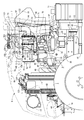
- FIG. 4 is an enlarged explanatory view of FIG. 3.
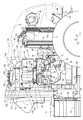
- FIG. 5 is an enlarged explanatory view of FIG. 4.
- FIG. 6 is an enlarged explanatory view of FIG. 5.
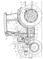
- FIGS. 1 to 6 a farm tractor 1 equipped with a diesel engine will be described with reference to FIGS.
- a farm tractor 1 as a work vehicle shown in FIGS. 1 to 5 is configured to perform a plowing work and the like for plowing a farm field by mounting a plow working machine (not shown).
- the left side in the forward direction of the tractor 1 is simply referred to as the left side
- the right side in the forward direction is also simply referred to as the right side.
- a farm tractor 1 as a work vehicle supports a traveling machine body 2 with a pair of left and right front wheels 3 and a pair of left and right rear wheels 4. 5 and driving the rear wheel 4 and the front wheel 3 with the diesel engine 5, the vehicle is configured to travel forward and backward.
- the upper surface side and the left and right side surfaces of the diesel engine 5 are covered with an openable / closable bonnet 6.
- a driving cabin 7 is installed as a driving unit on which an operator gets on.
- a front column 10 including a control seat 8 on which an operator sits, a control handle 9 as steering means, and the like.
- left and right boarding steps 12 are provided outside the boarding step 11 at the bottom of the cabin 7.
- left and right brake pedals 13, a clutch pedal 14, a transmission pedal 15, a forward / reverse switching lever 16 and the like are disposed as steering devices.
- the traveling machine body 2 also includes a mission case 17 for shifting the output from the diesel engine 5 and transmitting it to the rear wheels 4 (front wheels 3).
- the rear of the mission case 17 is connected to a tiller mechanism (not shown) and the like via a traction mechanism 21 such as a left and right lower link 18, a top link 19, and a left and right lift arm 20, and the like.
- the PTO shaft 22 provided on the rear side surface of 17 is configured to drive the tilling work machine and the like.
- the traveling machine body 2 of the tractor 1 includes a diesel engine 5, a transmission case 17, a clutch case 23 that connects them, a front chassis 24 that extends forward from the diesel engine 5, and the like.
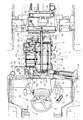
- an intake manifold 33 is disposed on one side surface of the cylinder head 32 of the diesel engine 5.
- the cylinder head 32 is mounted on a cylinder block 35 in which an engine output shaft (crank shaft) and a piston (not shown) are incorporated.
- An exhaust manifold 36 is disposed on the other side of the cylinder head 32.
- the front end side of the clutch case 23 is fixed to the rear surface of the engine via the flywheel housing 38.
- an oil pan 39 is disposed on the lower surface of the cylinder block 35
- a cooling fan 40 is disposed on the front surface side of the cylinder block 35
- a radiator 41 is installed facing the cooling fan 40.
- An oil cooler 42, an air cleaner 43, a battery 44, and the like are disposed on the front chassis 23 in front of the radiator 41.
- a front wheel drive shaft 46 that extracts the power of the diesel engine 5 from the transmission case 17 toward the front wheels 3 is disposed below the clutch case 23.
- an exhaust gas recirculation device (EGR) 47 that takes in exhaust gas for recirculation is arranged in the intake manifold 33.
- An air cleaner 43 is connected to the intake manifold 33 via an exhaust gas recirculation device 47. The external air that has been dedusted and purified by the air cleaner 43 is sent to the intake manifold 33 and supplied to each cylinder of the diesel engine 5.
- the diesel engine 5 is cooled by the cooling fan 40 wind. Further, as shown in FIG. 4, a fuel pump 52 and a common rail 53 for connecting a fuel tank 45 are provided to injectors (not shown) for four cylinders of the diesel engine 5.
- a common rail 53 and a fuel filter 54 are arranged on the intake manifold 33 installation side of the cylinder head 32, and a fuel pump 52 is arranged in the cylinder block 35 below the intake manifold 33.
- left and right fuel tanks 45 are mounted on the left and right sides of the clutch case 23 on the lower surface side of the boarding step 11.
- the high-pressure fuel is temporarily stored in the common rail 53, the high-pressure fuel in the common rail 53 is supplied into each cylinder of the diesel engine 5, and the fuel injection valves of the injectors are controlled to open and close. As a result, the high-pressure fuel in the common rail 53 is injected into each cylinder of the diesel engine 5. That is, by electronically controlling the fuel injection valve of each injector, the fuel injection pressure, injection timing, and injection period (injection amount) can be controlled with high accuracy. Therefore, nitrogen oxides (NOx) discharged from the diesel engine 5 can be reduced.
- NOx nitrogen oxides
- a first case 62 as a curate filter (DPF) and a second case 63 as a urea selective catalytic reduction (SCR) system for removing nitrogen oxides in exhaust gas of the diesel engine 5 are provided.
- DPF curate filter
- SCR selective catalytic reduction
- an oxidation catalyst 64 and a soot filter 65 are provided in the first case 62.
- the second case 63 includes an SCR catalyst 66 and an oxidation catalyst 67 for reducing urea selective catalyst.
- Exhaust gas discharged from each cylinder of the diesel engine 5 to the exhaust manifold 36 is discharged to the outside via the exhaust gas purification device 61 and the like.
- the exhaust gas purification device 61 is configured to reduce carbon monoxide (CO), hydrocarbons (HC), particulate matter (PM), and nitrogen oxides (NOx) in the exhaust gas of the diesel engine 5. is doing.
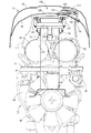
- the first case 62 is configured in a horizontally long and long cylindrical shape extending long in a direction parallel to the output shaft (crankshaft) of the diesel engine 5 (front-rear direction of the body) in plan view.
- a DPF inlet pipe 68 for taking in exhaust gas is provided on one end of the first case 62 in the cylindrical shape.
- the front and rear portions of the support table body 71 are connected to the front and rear surfaces of the cylinder head 32 via the front support leg body 69 and the rear support leg body 70.
- a case 62 and a second case 63 are placed. That is, the support table 71 is attached to the upper surface side of the diesel engine 5 through the front support leg 69 and the rear support leg 70.
- the first case 62 and the second case 63 are supported in parallel with the exhaust manifold 36 with the longitudinal directions of the cylindrical first case 62 and the second case 63 facing the front-rear direction of the diesel engine 5.
- a DPF inlet pipe 68 is communicated with an exhaust gas outlet of the exhaust manifold 36 via a supercharger 48 that forcibly sends air to the diesel engine 5, and the diesel engine 5 is passed from the DPF inlet pipe 68 into the first case 62. Introducing the exhaust gas.
- a DPF outlet pipe 72 for discharging exhaust gas is provided on the other end side of the cylindrical shape of the first case 62. The DPF outlet pipe 72 of the first case 62 is connected to the inlet side of the urea mixing pipe 73, and the exhaust gas of the first case 28 is introduced into the urea mixing pipe 73.
- an SCR inlet pipe 136 for taking in exhaust gas and an SCR outlet pipe 137 for discharging exhaust gas are provided on both sides of the second case 63 (one end side and the other end side in the exhaust gas movement direction).
- An SCR inlet pipe 136 is connected to the DPF outlet pipe 72 via a urea mixing pipe 73 so that the exhaust gas of the first case 62 is introduced into the second case 63.
- the DPF outlet pipe 135 and the urea mixing pipe 73 are detachably connected by a DPF outlet side flange body 141 to be bolted.
- the SCR inlet pipe 136 and the urea mixing pipe 73 are detachably connected by the SCR inlet side flange body 140.
- the first case 28, the second case 29, and the urea mixing pipe 39 are integrally coupled via the SCR inlet side flange body 140 and the DPF outlet side flange body 141.
- two fastening bands 84 and 85 are respectively attached to the upper surfaces of the first case 28 and the second case 29 in a semi-winding manner, and the lower ends of the fastening bands 84 and 85 are attached to the support table body 71.
- the bolt is fastened.
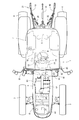
- a tail pipe 81 is erected on the front surface of the right corner of the driving cabin 7 in the front surface of the driving cabin 7, and the tail pipe 81 is directed toward the inside of the hood 56.
- the lower end side is extended, the lower end side of the tail pipe 81 is connected to the SCR outlet pipe 137 via the bellows-shaped flexible pipe 82, and the exhaust gas purified in the second case 63 is discharged from the tail pipe 81 to the operating cabin 7 It is discharged toward the top of the.
- a urea water tank 91 is installed on the left side of the bonnet 6 on the opposite side of the front side of the operation cabin 7 from the right side where the tail pipe 81 is disposed. That is, the tail pipe 81 is arranged on the right side of the rear part of the bonnet 6, while the urea water tank 91 is arranged on the left side of the rear part of the bonnet 6.
- a urea water tank 91 is mounted on the traveling machine body 2 (the bottom frame of the driving cabin 7 etc.) on the left rear side of the bonnet 6.
- An oil injection port 92 of the fuel tank 45 and a water injection port 93 of the urea water tank 71 are provided adjacent to each other at the lower front portion on the left side of the cabin 7.
- a tail pipe 81 is disposed on the front surface on the right side of the operating cabin 7 where the operator's boarding / alighting frequency is low, and an oil inlet 92 and a water inlet 93 are disposed on the front surface on the left side of the operating cabin 7 where the operator's boarding / alighting frequency is high.
- the driving cabin 7 is configured such that the operator can get on and off the control seat 8 from either the left side or the right side.
- a urea water injection pump 94 that pumps the urea aqueous solution in the urea water tank 91, an electric motor 95 that drives the urea water injection pump 94, and urea water in the urea water injection pump 94.
- a urea water injection nozzle 97 connected via the injection pipe 96 is provided.
- a urea water injection nozzle 76 is attached to the urea mixing pipe 39 via an injection base 77, and the urea aqueous solution is sprayed from the urea water injection nozzle 76 into the urea mixing pipe 39.
- the first case 62 includes a differential pressure sensor 111 that detects the accumulation state of particulate matter on the soot filter 65, an upstream gas temperature sensor 115 that detects an exhaust temperature on the exhaust gas intake side of the first case 62, and A downstream gas temperature sensor 116 that detects an exhaust gas temperature on the exhaust gas intake side of the soot filter 65 is provided, and an exhaust gas pressure on the inflow side of the soot filter 65 and an exhaust gas pressure on the outflow side of the soot filter 65 are provided.
- a difference (differential pressure of exhaust gas) is detected by the differential pressure sensor 111, and the exhaust gas temperature inside the first case 62 is detected by the temperature sensors 115 and 116.
- the second case 63 includes an SCR gas temperature sensor 117 that detects the exhaust temperature on the exhaust gas intake side of the SCR catalyst 66, and the exhaust gas temperature inside the second case 63 (SCR catalyst 66) is SCR. It is detected by the gas temperature sensor 117. That is, based on the detection results of the temperature sensors 115, 116, and 117, abnormalities in the exhaust gas temperature in the cases 62 and 63 are detected, and particulate matter in the exhaust gas collected by the soot filter 65 is detected.
- the soot filter 65 regeneration control (for example, fuel injection control or intake control of the diesel engine 5 for increasing the exhaust gas temperature) or the like is executed.
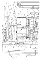
- the top plate portion of the bonnet 6 is formed in a double structure by the outer top plate 6a and the inner top plate 6b, and one or both of the first case 62 and the second case 63 are formed.
- the upper surface of the first case 62 or the second case 63 is covered with the inner top plate 6b.
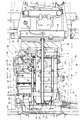
- an engine room frame 121 in which the bonnet 6 is arranged is provided.
- the engine room frame 121 is formed by the front and rear connection frames 124 that connect the upper ends of the front frame 123 and the front frame 123.
- the rear end of the bonnet support frame 126 is pivotally supported on the rear frame 122 via the opening / closing fulcrum shaft 125, and the front end of the bonnet support frame 126 is extended on the upper surface side of the diesel engine 5.
- the bonnet support frame 126 is integrally fixed to the lower surface side of the inner top plate 6b out of the double structure outer top plate 6a and inner top plate 6b, and the outer top plate 6a and the inner side are fixed to the bonnet support frame 126.
- the top plate 6b is installed, and the hood 6 is supported by the front opening / closing structure on the opening / closing fulcrum shaft 125 of the rear frame 122 via the bonnet support frame 126.
- a gas spring 127 is connected between the rear frame 122 and the bonnet support frame 126, and the opening force of the bonnet 6 is reduced by the gas spring 127.
- a sensor installation opening 131 is formed in the inner top plate 6b, and a sensor bracket 132 for supporting the exhaust differential pressure sensor 111 or the harness connector is provided.
- the fixing leg portion of the sensor bracket 132 is fastened and fixed, and the sensor bracket 132 is arranged in the heat shield space 130 inside the sensor installation opening 131 in the heat shield space 130 between the outer top plate 6a and the inner top plate 6b.
- a differential pressure sensor 111 integrally provided with an electrical wiring connector is attached to the sensor bracket 132.
- the differential pressure sensor 111 is connected to one end side of the upstream sensor pipe 133 and the downstream sensor pipe 134, respectively.
- the upstream and downstream sensor pipe boss bodies 151, 152 are arranged in the first case 62 so as to sandwich the soot filter 84 in the first case 62.
- the other end sides of the upstream sensor pipe 133 and the downstream sensor pipe 134 are connected to the sensor pipe boss bodies 151 and 152, respectively.
- an electrical wiring harness connector 153 of the upstream gas temperature sensor 115, an electrical wiring harness connector 154 of the downstream gas temperature sensor 116, and an electrical wiring harness connector 155 of the SCR gas temperature sensor 117 The harness connection direction is fixed to the sensor bracket 132 in the same orientation, and the differential pressure sensor 111 or the harness connector 153 is inserted into the heat shield space 130 between the outer top plate 6a and the inner top plate 6b via the sensor bracket 132. 154 and 155 are arranged.
- the first case 62, the second case 63, and the urea mixing tube 73 are arranged close to the lower surface side of the inner top plate 6b, and the lid plate body that opens and closes the sensor installation opening 131.
- 156, and a lid plate body 156 is detachably attached to the lower surface side of the inner top plate 6b, and hot air on the diesel engine 5 side is provided with a heat shield space 130 between the outer top plate 6a and the inner top plate 6b from the sensor installation opening 131. Prevents entry into the interior.
- an operation cabin 7 as an operation unit on which an operator is boarded
- a first case 62 for removing particulate matter in the exhaust gas of the diesel engine 5 and exhaust gas of the diesel engine 5.
- the work vehicle includes a hood 6 that covers the upper surface side of the diesel engine 5, and the first case 62 disposed on the upper surface side of the diesel engine 5 or
- the top plate portion of the bonnet 6 facing one or both of the second cases 63 is formed in a double structure by the outer top plate 6a and the inner top plate 6b.
- the heat retention of the first case 62 or the second case 63 can be easily improved while the bonnet 6 and the like can be easily prevented from being heated inappropriately.
- a heat shield space 130 in which the differential pressure sensor 111 and the like can be installed can be easily formed between the outer top plate 6a and the inner top plate 6b.
- the exhaust gas pressure sensor 111 or the exhaust gas temperature sensor (the upstream gas temperature sensor 115, the downstream gas temperature) for detecting the exhaust gas pressure or the exhaust gas temperature of the first case 62 or the second case 63.
- Sensor 116, SCR gas temperature sensor 117) and sensor bracket 132 that supports exhaust differential pressure sensor 111 or harness connectors 153, 154, 155, and is a heat shield between outer top plate 6a and inner top plate 6b.
- the differential pressure sensor 111 or the harness connectors 153, 154, 155 are arranged in the space 130 via the sensor bracket 132. Therefore, it is possible to easily reduce the influence of exhaust heat of the diesel engine 5 or the cases 62 and 63 on the harness to be connected to the differential pressure sensor 111 or the harness connectors 153, 154, 155. Can be improved.
- the rear side of the front and rear connecting frame 124 is connected to the rear frame 122 that is erected on the traveling machine body 2 on the operation cabin 7 side, and the front side that is erected on the traveling machine body 2 on the radiator 41 side.
- the front end side of the front / rear connecting frame 124 is connected to the frame 123 and the bonnet 6 is supported on the rear frame 122 via the opening / closing fulcrum shaft 125, and the bonnet is connected to the rear frame 122 via the opening / closing fulcrum shaft 125.
- a support frame 126 is provided, and an outer top plate 6 a and an inner top plate 6 b are installed on the bonnet support frame 126.
- the outer top plate 6a and the inner top plate 6b can be installed with high rigidity through the bonnet support frame 126 and the rear frame 122, the outer top plate 6a is made of a resin molding material that has poor heat resistance but is easy to process.
- the outer shape can be improved and the inner top plate 6b can be formed of a heat-resistant material having a simple sheet metal shape, and the heat resistance of the bonnet 6 can be improved.
- the structure includes a urea mixing pipe 73 that connects the second case 63 to the first case 62, and a urea water tank 91 that supplies urea water to the urea mixing pipe 73.
- the first case 62, the second case 62, and the urea mixing pipe 73 are arranged close to the lower surface side of the plate 6b, and the traveling machine body below the driving cabin 7 in the traveling machine body 2 on which the diesel engine 5 is mounted.
- a urea water tank 91 is disposed in FIG. Therefore, the first case 62, the second case 63, and the urea mixing pipe 73 can be compactly supported on the upper surface side of the diesel engine 5.
Abstract
Description
5 ディーゼルエンジン
6 ボンネット
6a 外側天板
6b 内側天板
7 運転キャビン(運転部)
41 ラジエータ
62 第1ケース
63 第2ケース
73 尿素混合管
91 尿素水タンク
111 差圧センサ
115 上流側ガス温度センサ
116 下流側ガス温度センサ
117 SCRガス温度センサ
122 後側フレーム
123 前側フレーム
124 前後連結フレーム
125 開閉支点軸
126 ボンネット支持枠体
130 遮熱空間
132 センサブラケット
153 ハーネスコネクタ
154 ハーネスコネクタ
155 ハーネスコネクタ 2 traveling
41
Claims (4)
- オペレータが搭乗する運転部と、エンジンの排気ガス中の粒子状物質を除去する第1ケースと、前記エンジンの排気ガス中の窒素酸化物質を除去する第2ケースを備える作業車両において、
前記エンジンの上面側を覆うボンネットを備える構造であって、前記エンジンの上面側に配置する前記第1ケースまたは前記第2ケースの一方または両方に対向する前記ボンネットの天板部を、外側天板と内側天板にて二重構造に形成したことを特徴とする作業車両。 In a work vehicle comprising an operating unit on which an operator is boarded, a first case for removing particulate matter in engine exhaust gas, and a second case for removing nitrogen oxide substance in engine exhaust gas,
A bonnet that covers the upper surface side of the engine, wherein the top plate portion of the bonnet facing one or both of the first case and the second case disposed on the upper surface side of the engine is an outer top plate. A work vehicle characterized in that it is formed in a double structure with an inner top plate. - 前記第1ケースまたは前記第2ケースの排気ガス圧力または排気ガス温度を検出する排気差圧センサまたは排気温度センサと、前記排気差圧センサまたはハーネスコネクタを支持するセンサブラケットを備える構造であって、前記外側天板と内側天板間の遮熱空間にセンサブラケットを介して前記センサまたはハーネスコネクタを配置したことを特徴とする請求項1に記載の作業車両。 An exhaust differential pressure sensor or an exhaust temperature sensor for detecting an exhaust gas pressure or an exhaust gas temperature of the first case or the second case, and a sensor bracket for supporting the exhaust differential pressure sensor or a harness connector, The work vehicle according to claim 1, wherein the sensor or the harness connector is disposed via a sensor bracket in a heat shield space between the outer top plate and the inner top plate.
- 前記運転部側の走行機体に立設させる後側フレームに前後連結フレームの後端側を連結させ、ラジエータ側の走行機体に立設させる前側フレームに前後連結フレームの前端側を連結させると共に、前記後側フレームに開閉支点軸を介してボンネットを支持させる構造であって、前記後側フレームに開閉支点軸を介してボンネット支持枠体を設け、前記ボンネット支持枠体に前記外側天板と内側天板を架設したことを特徴とする請求項1に記載の作業車両。 Connecting the rear end side of the front-rear connecting frame to the rear frame to be erected on the traveling unit body on the driving unit side, connecting the front end side of the front-rear connecting frame to the front frame to be erected on the radiator side traveling unit body, and A bonnet is supported on the rear frame via an opening / closing fulcrum shaft, and a bonnet support frame is provided on the rear frame via an opening / closing fulcrum shaft, and the outer top plate and the inner ceiling are provided on the bonnet support frame. The work vehicle according to claim 1, further comprising a plate.
- 前記第1ケースに第2ケースを接続する尿素混合管と、尿素混合管に尿素水を供給する尿素水タンクを備える構造であって、前記内側天板の下面側に近接させて、前記第1ケースと前記第2ケースと前記尿素混合管を配置させると共に、前記エンジンが搭載される走行機体のうち、前記運転部下側の走行機体に前記尿素水タンクを配置したことを特徴とする請求項1に記載の作業車両。 A urea mixing pipe that connects the first case to the second case, and a urea water tank that supplies urea water to the urea mixing pipe, the first mixing case being close to the lower surface side of the inner top plate, 2. The urea water tank is disposed in a traveling machine body below the driving unit among a traveling machine body on which the engine is mounted, and the case, the second case, and the urea mixing pipe are disposed. The work vehicle as described in.
Priority Applications (4)
| Application Number | Priority Date | Filing Date | Title |
|---|---|---|---|
| CN201480067066.0A CN105813927A (en) | 2013-12-11 | 2014-12-10 | Working vehicle |
| EP14868837.7A EP3081460A4 (en) | 2013-12-11 | 2014-12-10 | Working vehicle |
| US15/102,742 US9783042B2 (en) | 2013-12-11 | 2014-12-10 | Working vehicle |
| KR1020167011433A KR20160096586A (en) | 2013-12-11 | 2014-12-10 | Working vehicle |
Applications Claiming Priority (2)
| Application Number | Priority Date | Filing Date | Title |
|---|---|---|---|
| JP2013-256333 | 2013-12-11 | ||
| JP2013256333A JP6193109B2 (en) | 2013-12-11 | 2013-12-11 | Work vehicle |
Publications (1)
| Publication Number | Publication Date |
|---|---|
| WO2015087929A1 true WO2015087929A1 (en) | 2015-06-18 |
Family
ID=53371229
Family Applications (1)
| Application Number | Title | Priority Date | Filing Date |
|---|---|---|---|
| PCT/JP2014/082731 WO2015087929A1 (en) | 2013-12-11 | 2014-12-10 | Working vehicle |
Country Status (6)
| Country | Link |
|---|---|
| US (1) | US9783042B2 (en) |
| EP (1) | EP3081460A4 (en) |
| JP (1) | JP6193109B2 (en) |
| KR (1) | KR20160096586A (en) |
| CN (1) | CN105813927A (en) |
| WO (1) | WO2015087929A1 (en) |
Cited By (1)
| Publication number | Priority date | Publication date | Assignee | Title |
|---|---|---|---|---|
| EP3330503A4 (en) * | 2015-07-31 | 2019-01-02 | Yanmar Co., Ltd. | Work vehicle |
Families Citing this family (9)
| Publication number | Priority date | Publication date | Assignee | Title |
|---|---|---|---|---|
| JP6275552B2 (en) * | 2014-05-29 | 2018-02-07 | ヤンマー株式会社 | Work vehicle |
| JP6393777B2 (en) * | 2014-11-21 | 2018-09-19 | 株式会社Kcm | Industrial vehicle |
| JP6447077B2 (en) * | 2014-12-11 | 2019-01-09 | 井関農機株式会社 | Work vehicle |
| US10308108B2 (en) | 2015-03-30 | 2019-06-04 | Kubota Corporation | Working machine |
| US10876471B2 (en) * | 2016-04-12 | 2020-12-29 | Cummins Power Generation Limited | Modular genset enclosure components |
| JP6619375B2 (en) * | 2017-03-24 | 2019-12-11 | ヤンマー株式会社 | Engine equipment |
| JP6815255B2 (en) * | 2017-03-30 | 2021-01-20 | ヤンマーパワーテクノロジー株式会社 | Tractor |
| JP6451805B1 (en) * | 2017-08-22 | 2019-01-16 | マツダ株式会社 | Engine heat insulation structure |
| JP6904323B2 (en) * | 2018-11-28 | 2021-07-14 | 井関農機株式会社 | Work vehicle |
Citations (10)
| Publication number | Priority date | Publication date | Assignee | Title |
|---|---|---|---|---|
| JP2001171563A (en) * | 1999-11-23 | 2001-06-26 | Deere & Co | Assembly for tractor engine enclosure |
| JP2004256006A (en) * | 2003-02-26 | 2004-09-16 | Yanmar Agricult Equip Co Ltd | Tractor |
| JP2006062425A (en) * | 2004-08-24 | 2006-03-09 | Yanmar Co Ltd | Hood and manufacturing method for hood |
| JP2008240677A (en) * | 2007-03-28 | 2008-10-09 | Komatsu Ltd | Construction vehicle |
| JP2009074420A (en) | 2007-09-20 | 2009-04-09 | Hino Motors Ltd | Exhaust emission control device |
| JP2011230638A (en) * | 2010-04-27 | 2011-11-17 | Iseki & Co Ltd | Tractor |
| US20110283687A1 (en) | 2008-12-19 | 2011-11-24 | Agco Gmbh | Exhaust systems for vehicles |
| JP2013018325A (en) * | 2011-07-08 | 2013-01-31 | Mitsubishi Agricultural Machinery Co Ltd | Work vehicle |
| JP2013151185A (en) * | 2012-01-24 | 2013-08-08 | Iseki & Co Ltd | Working vehicle |
| JP2013173428A (en) * | 2012-02-24 | 2013-09-05 | Iseki & Co Ltd | Work vehicle |
Family Cites Families (16)
| Publication number | Priority date | Publication date | Assignee | Title |
|---|---|---|---|---|
| US5564514A (en) * | 1994-09-09 | 1996-10-15 | New Holland North America, Inc. | Adjustable tractor hood lift mechanism |
| JPH1178987A (en) * | 1997-09-05 | 1999-03-23 | Kanzaki Kokyukoki Mfg Co Ltd | Prime mover part structure of tractor |
| JP2002021565A (en) * | 2000-07-11 | 2002-01-23 | Komatsu Ltd | Engine enclosure for construction vehicle |
| JP2003020936A (en) * | 2001-07-03 | 2003-01-24 | Komatsu Ltd | ARRANGEMENT STRUCTURE FOR LIQUID REDUCING AGENT TANK FOR NOx REDUCTION CATALYST |
| JP5273933B2 (en) * | 2007-03-28 | 2013-08-28 | 株式会社小松製作所 | Construction vehicle |
| JP5239253B2 (en) * | 2007-08-14 | 2013-07-17 | 日産自動車株式会社 | Hood flip-up device |
| JP5184387B2 (en) * | 2009-01-09 | 2013-04-17 | ヤンマー株式会社 | Bonnet structure |
| US20100186381A1 (en) * | 2009-01-26 | 2010-07-29 | Caterpillar Inc | Exhaust system thermal enclosure |
| US20100301638A1 (en) * | 2009-05-29 | 2010-12-02 | Hinshaw Eric J | Integrated Air Intake System |
| JP5356341B2 (en) * | 2010-09-16 | 2013-12-04 | 日立建機株式会社 | Construction machinery |
| GB201104158D0 (en) * | 2011-03-11 | 2011-04-27 | Agco Int Gmbh | Engine hood arrangement |
| US8626407B2 (en) * | 2011-07-26 | 2014-01-07 | Kubota Corporation | Work vehicle |
| JP5865040B2 (en) * | 2011-11-30 | 2016-02-17 | 株式会社クボタ | Work vehicle |
| WO2013115398A1 (en) * | 2012-02-03 | 2013-08-08 | 日立建機株式会社 | Work vehicle |
| JP5474155B1 (en) * | 2012-10-16 | 2014-04-16 | 株式会社小松製作所 | Exhaust treatment unit and method of attaching and removing exhaust treatment unit |
| JP5382672B1 (en) * | 2013-03-29 | 2014-01-08 | 株式会社小松製作所 | Bulldozer |
-
2013
- 2013-12-11 JP JP2013256333A patent/JP6193109B2/en active Active
-
2014
- 2014-12-10 CN CN201480067066.0A patent/CN105813927A/en active Pending
- 2014-12-10 WO PCT/JP2014/082731 patent/WO2015087929A1/en active Application Filing
- 2014-12-10 US US15/102,742 patent/US9783042B2/en active Active
- 2014-12-10 KR KR1020167011433A patent/KR20160096586A/en active IP Right Grant
- 2014-12-10 EP EP14868837.7A patent/EP3081460A4/en not_active Withdrawn
Patent Citations (10)
| Publication number | Priority date | Publication date | Assignee | Title |
|---|---|---|---|---|
| JP2001171563A (en) * | 1999-11-23 | 2001-06-26 | Deere & Co | Assembly for tractor engine enclosure |
| JP2004256006A (en) * | 2003-02-26 | 2004-09-16 | Yanmar Agricult Equip Co Ltd | Tractor |
| JP2006062425A (en) * | 2004-08-24 | 2006-03-09 | Yanmar Co Ltd | Hood and manufacturing method for hood |
| JP2008240677A (en) * | 2007-03-28 | 2008-10-09 | Komatsu Ltd | Construction vehicle |
| JP2009074420A (en) | 2007-09-20 | 2009-04-09 | Hino Motors Ltd | Exhaust emission control device |
| US20110283687A1 (en) | 2008-12-19 | 2011-11-24 | Agco Gmbh | Exhaust systems for vehicles |
| JP2011230638A (en) * | 2010-04-27 | 2011-11-17 | Iseki & Co Ltd | Tractor |
| JP2013018325A (en) * | 2011-07-08 | 2013-01-31 | Mitsubishi Agricultural Machinery Co Ltd | Work vehicle |
| JP2013151185A (en) * | 2012-01-24 | 2013-08-08 | Iseki & Co Ltd | Working vehicle |
| JP2013173428A (en) * | 2012-02-24 | 2013-09-05 | Iseki & Co Ltd | Work vehicle |
Non-Patent Citations (1)
| Title |
|---|
| See also references of EP3081460A4 |
Cited By (3)
| Publication number | Priority date | Publication date | Assignee | Title |
|---|---|---|---|---|
| EP3330503A4 (en) * | 2015-07-31 | 2019-01-02 | Yanmar Co., Ltd. | Work vehicle |
| US10449851B2 (en) | 2015-07-31 | 2019-10-22 | Yanmar Co., Ltd. | Work vehicle |
| EP3663549A1 (en) * | 2015-07-31 | 2020-06-10 | Yanmar Co., Ltd. | Work vehicle |
Also Published As
| Publication number | Publication date |
|---|---|
| EP3081460A4 (en) | 2017-08-02 |
| CN105813927A (en) | 2016-07-27 |
| US9783042B2 (en) | 2017-10-10 |
| JP6193109B2 (en) | 2017-09-06 |
| JP2015113003A (en) | 2015-06-22 |
| EP3081460A1 (en) | 2016-10-19 |
| KR20160096586A (en) | 2016-08-16 |
| US20160311314A1 (en) | 2016-10-27 |
Similar Documents
| Publication | Publication Date | Title |
|---|---|---|
| JP6193109B2 (en) | Work vehicle | |
| US9855837B2 (en) | Work vehicle | |
| WO2014157285A1 (en) | Engine device for work vehicles | |
| JP6200682B2 (en) | Tractor | |
| JP5918154B2 (en) | Engine device for work vehicle | |
| WO2016056420A1 (en) | Engine device | |
| WO2015064448A1 (en) | Engine device of work vehicle | |
| WO2015093375A1 (en) | Working vehicle | |
| JP2017025743A (en) | Engine device | |
| WO2015060355A1 (en) | Engine device for work vehicle | |
| JP6177005B2 (en) | Work vehicle | |
| JP6162519B2 (en) | Tractor | |
| WO2015012168A1 (en) | Industrial vehicle | |
| KR101910755B1 (en) | Engine device | |
| JP6343218B2 (en) | Engine equipment | |
| JP6177118B2 (en) | Tractor | |
| JP2015117597A (en) | Work vehicle | |
| JP2015086713A (en) | Engine device of work vehicle | |
| JP6120796B2 (en) | Work vehicle | |
| JP6151629B2 (en) | Work vehicle | |
| WO2015087928A1 (en) | Working vehicle | |
| WO2015012169A1 (en) | Working vehicle | |
| JP6343219B2 (en) | Engine equipment | |
| JP6305304B2 (en) | Engine equipment | |
| JP2015020714A (en) | Work vehicle |
Legal Events
| Date | Code | Title | Description |
|---|---|---|---|
| 121 | Ep: the epo has been informed by wipo that ep was designated in this application |
Ref document number: 14868837 Country of ref document: EP Kind code of ref document: A1 |
|
| ENP | Entry into the national phase |
Ref document number: 20167011433 Country of ref document: KR Kind code of ref document: A |
|
| REEP | Request for entry into the european phase |
Ref document number: 2014868837 Country of ref document: EP |
|
| WWE | Wipo information: entry into national phase |
Ref document number: 15102742 Country of ref document: US Ref document number: 2014868837 Country of ref document: EP |
|
| NENP | Non-entry into the national phase |
Ref country code: DE |