WO2015087841A1 - Motor - Google Patents
Motor Download PDFInfo
- Publication number
- WO2015087841A1 WO2015087841A1 PCT/JP2014/082452 JP2014082452W WO2015087841A1 WO 2015087841 A1 WO2015087841 A1 WO 2015087841A1 JP 2014082452 W JP2014082452 W JP 2014082452W WO 2015087841 A1 WO2015087841 A1 WO 2015087841A1
- Authority
- WO
- WIPO (PCT)
- Prior art keywords
- terminal
- connector
- terminal support
- coil
- wiring member
- Prior art date
Links
Images

Classifications
-
- H—ELECTRICITY
- H02—GENERATION; CONVERSION OR DISTRIBUTION OF ELECTRIC POWER
- H02K—DYNAMO-ELECTRIC MACHINES
- H02K3/00—Details of windings
- H02K3/46—Fastening of windings on the stator or rotor structure
- H02K3/52—Fastening salient pole windings or connections thereto
- H02K3/521—Fastening salient pole windings or connections thereto applicable to stators only
- H02K3/525—Annular coils, e.g. for cores of the claw-pole type
-
- H—ELECTRICITY
- H02—GENERATION; CONVERSION OR DISTRIBUTION OF ELECTRIC POWER
- H02K—DYNAMO-ELECTRIC MACHINES
- H02K5/00—Casings; Enclosures; Supports
- H02K5/04—Casings or enclosures characterised by the shape, form or construction thereof
- H02K5/12—Casings or enclosures characterised by the shape, form or construction thereof specially adapted for operating in liquid or gas
- H02K5/128—Casings or enclosures characterised by the shape, form or construction thereof specially adapted for operating in liquid or gas using air-gap sleeves or air-gap discs
-
- H—ELECTRICITY
- H02—GENERATION; CONVERSION OR DISTRIBUTION OF ELECTRIC POWER
- H02K—DYNAMO-ELECTRIC MACHINES
- H02K5/00—Casings; Enclosures; Supports
- H02K5/04—Casings or enclosures characterised by the shape, form or construction thereof
- H02K5/22—Auxiliary parts of casings not covered by groups H02K5/06-H02K5/20, e.g. shaped to form connection boxes or terminal boxes
- H02K5/225—Terminal boxes or connection arrangements
-
- H—ELECTRICITY
- H02—GENERATION; CONVERSION OR DISTRIBUTION OF ELECTRIC POWER
- H02K—DYNAMO-ELECTRIC MACHINES
- H02K7/00—Arrangements for handling mechanical energy structurally associated with dynamo-electric machines, e.g. structural association with mechanical driving motors or auxiliary dynamo-electric machines
- H02K7/14—Structural association with mechanical loads, e.g. with hand-held machine tools or fans
-
- H—ELECTRICITY
- H02—GENERATION; CONVERSION OR DISTRIBUTION OF ELECTRIC POWER
- H02K—DYNAMO-ELECTRIC MACHINES
- H02K2213/00—Specific aspects, not otherwise provided for and not covered by codes H02K2201/00 - H02K2211/00
- H02K2213/03—Machines characterised by numerical values, ranges, mathematical expressions or similar information
Definitions
- the present invention relates to a motor.
- Patent Document 1 discloses a stator structure of a motor.
- a resin cover that accommodates the stator assembly is employed.
- the cover has a peripheral wall portion surrounding the outer periphery of the stator assembly, and a resin connector cover for covering the connector is integrally formed on the peripheral wall portion.
- the inner side of the cover and the inner side of the connector cover communicate with each other through an opening provided in the peripheral wall portion, and the plurality of coil terminals extending in the radial direction from the stator assembly are flexible boards on the inner side of the connector cover. Are connected to the corresponding connector terminals.
- a resin support member that supports the connector terminal is arranged inside the connector cover, and the connection portion with the connector terminal on the board is connected to the connector terminal by soldering while in contact with the support member. It has come to be.
- the support member may be melted by heat during soldering. In such a case, the support strength of the connector terminal in the support member is reduced.
- the present invention A coil terminal extending from the stator surrounding the rotor is connected to a connector terminal supported by a resin-made terminal support portion via a flexible plate-like wiring member, and at the connection portion between the connector terminal and the wiring member,
- the terminal support portion The motor has a configuration in which an insulating heat insulating member is provided between the wiring member and the wiring member.
- the insulating heat insulating member is provided between the terminal support portion and the wiring member, the influence of the soldering heat when connecting the connector terminal and the wiring member is affected by the terminal support portion. Can be suitably prevented.
- FIG. 2 is a sectional view taken along line X1-X1 in FIG. It is a perspective view which decomposes
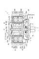
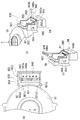
- FIG. 1 is a cross-sectional view of a valve drive device 1 according to an embodiment.
- 2 is a cross-sectional view taken along line X1-X1 in FIG.
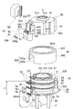
- FIG. 3 is an exploded perspective view of the valve drive device 1 on the motor M side. In FIG. 3, a portion of the stator assembly 40 formed of resin is hatched.
- the valve drive device 1 is a flow path through which fluid (here, refrigerant) can circulate between a refrigerator (not shown) that is an external device.
- a refrigerator not shown
- the valve portion 70 is driven by the motor M, and the fluid introduced into the fluid chamber S is led out from the fluid outlet pipes 3 and 4 to the refrigerator side.
- a claw pole type stepping motor in which a pair of stator sets 50 ⁇ / b> A and 50 ⁇ / b> B (A phase coil and B phase coil) are arranged in the direction of the axis X of the rotation axis of the rotor 30 is employed. .
- a fluid chamber S is formed between the bottom plate portion 10 and the partition wall 20 by a bottomed cylindrical partition wall 20 fixed to the upper surface (the surface on the rotor 30 side) of the bottom plate portion 10.
- the partition wall 20 is provided with the bottom portion 20 a facing upward (on the rotor 30 side) opposite to the bottom plate portion 10.
- the partition wall 20 has an outer shape expanded in two steps in a direction away from the bottom portion 20a, and includes a small diameter portion 201 on the bottom portion 20a side and a large diameter portion 202 on the bottom plate portion 10 side.
- a stepped portion 11 is provided over the entire periphery to which the tip end 202 a of the large diameter portion 202 is fitted, and the partition wall 20 has the tip end 202 a of the large diameter portion 202 on the stepped portion 11. And is fixed to the bottom plate portion 10. Further, the valve drive device 1 is used in an arrangement (see FIG. 1) in which the rotor 30 of the motor M is directed upward and the fluid chamber S is directed downward.
- the rotor 30 of the motor M is provided in a state of being extrapolated to the shaft member 21.
- the shaft member 21 is provided along the axis X of the rotation shaft of the rotor 30, one end 21 a of the shaft member 21 is supported by the recess 20 b of the bottom portion 20 a, and the other end 21 b is The shaft member 21 is brazed at the hole 10a of the bottom plate portion 10 and is prevented from rotating.
- the rotor 30 is rotatably supported, and rotates around the axis X when the motor M is driven.
- the rotor 30 includes a base portion 31 having a bearing portion 31 a that is extrapolated to the shaft member 21, and magnets 32 in which N and S phases are alternately arranged in the circumferential direction around the axis X.
- the magnet 32 is formed integrally with the base 31 by insert molding.
- the magnet 32 is provided over the entire circumference in the circumferential direction around the axis X.
- a transmission shaft 33 that transmits the rotation of the rotor 30 to a valve portion 70 described later is inserted between the bearing portion 31 a and the base portion 31 and fixed to the lower portion of the base portion 31 on the bottom plate portion 10 side.
- the transmission shaft 33 is rotatably supported by the shaft member 21, and rotates around the axis line X integrally with the rotor 30.
- the transmission shaft 33 extends downward along the axis X on the side of the bottom plate portion 10, and the tip end portion 33 a is in contact with the upper surface 10 b of the bottom plate portion 10.
- the rotor 30 is urged downward on the bottom plate portion 10 side by a spring Sp extrapolated to the one end 21a side of the shaft member 21, and the tip portion of the transmission shaft 33 is urged by the urging force of the spring Sp.
- 33a is always brought into contact with the upper surface 10b of the bottom plate portion 10, and the axial line X of the rotor 30 is positioned in the axial direction.
- An upper side (rotor 30 side) of the distal end portion 33a of the transmission shaft 33 is a large diameter portion 33b having a diameter larger than that of the distal end portion 33a, and an outer periphery of a gear 71 described later is provided on the outer periphery of the large diameter portion 33b.
- the tooth part 33c which meshes with the tooth part 71g provided in is provided (see FIG. 2).
- the small-diameter portion 201 of the partition wall 20 that accommodates the rotor 30 is formed in a cylindrical shape that surrounds the magnet 32 of the rotor 30 at a predetermined interval, and the stator assembly 40 is disposed on the outer periphery of the small-diameter portion 201. Is attached by extrapolation.
- the disk portion 203 that connects the small diameter portion 201 and the large diameter portion 202 is provided orthogonal to the axis X, and the stator assembly 40 extrapolated to the small diameter portion 201 by the disk portion 203.
- the two stator sets 50A and 50B are arranged on the radially outer side of the rotor 30 (magnet 32).
- the partition wall 20 Since the magnet 32 of the rotor 30 is driven by a magnetic force from a stator assembly 40 described later via the partition wall 20, the partition wall 20 is made of a nonmagnetic material. Further, the partition wall 20 is made of metal so as to withstand the pressure of the fluid chamber S. For this reason, the partition 20 is comprised with the stainless steel which is a nonmagnetic metal.
- the stator assembly 40 includes two stator sets 50A and 50B arranged so as to overlap each other in the axial direction of the axis X, and the stator assembly 40 has outer peripheries of the stator sets 50A and 50B.
- a surrounding outer stator core 59 is attached by extrapolation.
- the outer stator core 59 is formed by pressing a magnetic plate like the inner stator cores 51 and 52 to be described later.
- Each of the stator sets 50A and 50B has a basic configuration in which a drive coil 54 wound around the outer periphery of a bobbin 53 is disposed between a pair of inner stator cores 51 and 52 that are spaced apart in the axial direction.
- the bobbin 53 is a resin molded body (insulator) in which the inner stator cores 51 and 52 of the stator assemblies 50A and 50B are embedded by insert molding, and is formed integrally with a terminal holding portion 55 described later. ing.
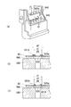
- FIG. 4A is an enlarged cross-sectional view of the main part in FIG. 1, and FIG. 4B is an enlarged view of a region A in FIG.
- the inner stator cores 51 and 52 are formed to stand in the axis X direction from the inner periphery of the ring-shaped flange portions 510 and 520 arranged in a direction orthogonal to the axis X and the flange portions 510 and 520.
- the pole teeth 511 and 521 are provided at equal intervals in the circumferential direction around the axis X on the inner diameter side of the flange portions 510 and 520.
- the pair of inner stator cores 51 and 52 of the stator sets 50A and 50B are arranged such that the pole teeth 511 of one inner stator core 51 and the pole teeth 521 of the other inner stator core 52 are alternately arranged in the circumferential direction around the axis X. As shown in the figure, the pole teeth 511 and 521 are arranged to face each other.
- a cylindrical base portion 530 of a bobbin 53 around which a coil is wound is located on the outer side in the radial direction of the pole teeth 511 and 521, and the outer side in the radial direction is located at both ends of the base portion 530 in the axial direction of the axis X.
- the flanges 531 and 532 extending in the circumferential direction are provided over the entire circumference in the circumferential direction around the axis X.
- the inner stator core 51 of the stator assembly 50A and the inner stator core 52 of the stator assembly 50B are in contact with the flange portions 510 and 520 (see FIG. 4) in the axial direction of the axis X. It is provided in a state of letting it. And these flange parts 510 and 520 are hold
- the pole teeth 511 and 521 are exposed on the inner diameter side of the base portion 530 of the bobbin 53, and the surface of the flange portions 510 and 520 on the drive coil 54 side is the flange portion. 531 and 532 are covered with resin.
- a ring-shaped attachment portion 57 (see FIGS. 2 and 3) is formed of a resin material that covers the upper surface on the inner diameter side of the flange portion 510 of the stator assembly 50B. Are fitted with a fitting wall 91c of an upper cover member 90 to be described later.
- a ring-shaped contact portion 58 (see FIG. 2) is formed of a resin material that covers the lower surface on the inner diameter side of the flange portion 520 of the stator assembly 50A. The contact portion 58 comes into contact with the disk portion 203 at the boundary between the small diameter portion 201 and the large diameter portion 202 from the axis X direction when the stator assembly 40 is extrapolated to the small diameter portion 201 of the partition wall 20.
- the positioning of the stator assembly 40 in the axial direction is performed by a contact portion 58 that is in contact with the disc portion 203.
- notches 510b and 520b that are recessed toward the axis X side are formed in a part of the outer peripheral portion, and the notches of the flange portions 510 and 520 are formed.
- the notches 510b and 520b are provided at positions overlapping when viewed from the axial direction of the axis X.
- the terminal holding portion 55 is provided by using the notches 510b and 520b.
- the terminal holding portion 55B of the stator assembly 50B is provided across the notches 510b and 520b of the flange portions 510 and 520.
- the terminal holding portion 55B is formed integrally with the flange portions 532 and 531 of the bobbin 53 located on both sides of the flange portions 510 and 520, and has a predetermined thickness in the axial direction of the axis X.
- the terminal holding portion 55 ⁇ / b> A of the stator set 50 ⁇ / b> A is provided in the notch portion 520 b of the flange portion 520 of the inner stator core 52.
- the terminal holding portion 55A is formed integrally with the flange portion 532 of the bobbin 53 of the stator assembly 50A, and has a predetermined thickness in the axial direction of the axis X.
- the terminal holding portion 55A of the stator set 50A and the terminal holding portion 55B of the stator set 50B are provided with an interval in the axis X direction.
- a plurality of coil terminals 56 are press-fitted and supported by the terminal holding portions 55A and 55B of the stator assemblies 50A and 50B, and the plurality of coil terminals 56 are provided so as to protrude radially outward from the stator assembly 40.
- the base end of the coil terminal 56 is located in the notches 510b and 520b.
- a cutout portion 593 for avoiding interference with the coil terminal 56 is formed on the peripheral wall portion 592 surrounding the outer periphery of the stator assemblies 50A and 50B.
- the opening 92a for avoiding interference with the coil terminal 56 is also provided in the peripheral wall 92 of the upper cover member 90 described later (see FIG. 1).
- the outer stator core 59 has a bottomed cylindrical shape, and an opening 591 a through which the bottom 20 a side of the partition wall 20 can be inserted is provided at the center of the bottom 591.
- the surrounding wall part 592 provided over the perimeter of the bottom part 591 has comprised the cylindrical shape which surrounds the flange parts 510 and 520 of stator assembly 50A, 50B over a perimeter.
- the coil terminal 56 is a conductive pin having a linearly extending rod shape.
- the coil terminal 56 passes through an opening 92 a provided in the upper cover member 90, and the tip end side thereof is connected to the connector cover portion. 93 (accommodating portion 95).
- each of the coil terminals 56 supported by the terminal holding portions 55A and 55B corresponds to each other via a flexible common substrate 60 (hereinafter also referred to as a substrate 60) made of polyimide resin. Connected to the connector terminal 61. Note that each of the coil terminals 56 is connected to a corresponding wiring among the wirings provided on the substrate 60 on the surface of the substrate 60 opposite to the drive coil 54 by soldering.
- the upper cover member 90 is a member that accommodates the stator assembly 40 and the outer stator core 59 of the motor M.
- the upper cover member 90 covers the upper surface of the stator assembly 40, and the outer periphery of the outer stator core 59.
- a peripheral wall portion 92 that surrounds the connector wall portion 92, and a connector cover portion 93 is formed integrally with the peripheral wall portion 92.
- the upper cover member 90 is formed by resin molding a mixed resin of polycarbonate and ABS resin.
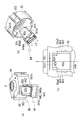
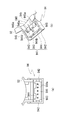
- FIG. 5 is a diagram for explaining the connector cover portion 93 of the upper cover member 90, and (a) is a perspective view of the connector portion 94 and the accommodating portion 95 of the connector cover portion 93 as viewed from the upper right side, (B) is the perspective view which looked at the connector part 94 and the accommodating part 95 from diagonally downward, (c) is the figure which looked at the accommodating part 95 from radial direction.
- 6A and 6B are diagrams illustrating the connector cover portion 93, where FIG. 6A is a view seen from the upper side in the axis X direction, FIG. 6B is a perspective view, and FIG. 6C is a connector cover. It is a figure explaining attachment of the heat insulation member 946 with respect to the terminal support part 940 of the part 93.
- FIG. 7A and 7B are views for explaining the connector portion 94, where FIG. 7A is a view seen from the lower side in the axis X direction, and FIG. 7B is a perspective view seen from the oblique lower side in the axis X direction.
- the peripheral wall portion 92 of the upper cover member 90 has an annular shape as viewed from the axial direction of the axis X, and in the valve drive device 1, the peripheral wall portion 92 surrounds the outer periphery of the outer stator core 59. Is provided.
- the lower end 92b (see FIG. 3) of the peripheral wall portion 92 is lower in the axis X direction than the coil terminal 56 and the drive coil 54 disposed on the inner side of the upper cover member 90 and the connector cover portion 93 (the fluid outlet tube 3, 4 side), water applied to the peripheral wall portion 92 is suitably prevented from reaching conductive portions such as the coil terminal 56 and the drive coil 54.
- the peripheral wall portion 92 a region that interferes with the coil terminal 56 is cut out when viewed from the radial direction, and the cutout region is an opening through which the coil terminal 56 that extends in the radial direction from the stator assembly 40 passes.
- the portion 92a is formed.
- the opening 92a is formed in a height range from the lower end of the peripheral wall portion 92 to the vicinity of the cover portion 91 (see FIG. 5B), and the upper side 92a1 of the opening 92a is A position offset from the cover portion 91 to the lower side (the fluid outlet pipes 3 and 4 side) extends in parallel to the cover portion 91.
- Both sides 92a2 and 92a2 of the opening 92a in the circumferential direction of the peripheral wall 92 extend linearly along the axis X, and the opening 92a has a substantially rectangular shape when viewed from the radial direction (see FIG. 5 (c)).
- protruding portions 921 are provided on both sides of the upper side 92a1 so as to protrude radially outward.
- the substrate 92 is in contact with the protruding portion 921 from the outside in the radial direction (see FIG. 1), and the positioning of the substrate 60 in the radial direction is performed by the protruding portion 921.
- an engaged portion 922 to be engaged with an engaging arm 84 of the lower cover member 80 to be described later is provided at a position on the opposite side of the opening portion 92 a across the axis X. Yes.
- the upper cover member 90 is formed integrally with the connector portion 94 and the housing portion 95 of the connector cover portion 93.
- a connector cover portion 93 that covers the opening 92a is provided outside the opening 92a in the radial direction.
- the connector cover portion 93 extends downward (toward the fluid outlet pipes 3 and 4) from the radially outer side of the peripheral wall portion 92, and is positioned below the opening portion 92a (toward the fluid outlet pipes 3 and 4).
- a connector portion 94, a housing portion 95 that houses the substrate 60 that connects the connector terminal 61 provided on the connector portion 94 and the coil terminal 56, and a cap 96 that seals the opening 930 of the housing portion 95. Have.
- a terminal support portion 940 is provided at a position on the radially outer side of the large diameter portion 202.
- the connector terminal 61 described above is provided in the terminal support portion 940. A plurality of them are provided at intervals in the circumferential direction around the axis X (see FIG. 3).
- Each of the connector terminals 61 is provided so as to penetrate the terminal support portion 940 in the thickness direction (axis X direction), and each of the connector terminals 61 is positioned below the above-described coil terminal 56 as viewed from the radial direction. In addition, it is provided in a direction substantially orthogonal to the coil terminal 56.
- Each of the connector terminals 61 is connected to the corresponding coil terminal 56 via the substrate 60, and each of the connector terminals 61 is provided on the substrate 60 on the surface of the substrate 60 opposite to the terminal support portion 940.
- the corresponding wirings of the wirings are connected by soldering to land portions 601A formed so as to surround the periphery of the terminal holes 601.
- each of the connector terminals 61 is inserted into a circular terminal hole 601 provided on one side of the substrate 60 and connected to the corresponding wiring by soldering.
- connection portion (soldering portion) between the connector terminal 61 and the substrate 60 is located below (terminal support portion 940) from the connection portion (soldering portion) between the coil terminal 56 and the substrate 60 at a predetermined height h in the axis X direction. It is provided at a position offset in the direction of
- the substrate 60 that connects the coil terminal 56 and the connector terminal 61 has the curved portion 60c as a boundary, the one end 60a side in the direction along the axis X, and the other end 60b side in the direction orthogonal to the axis X. It is directed in the direction along which it is bent so as to be substantially L-shaped when viewed from the side surface of the substrate 60 (see FIG. 4A).
- a restoring force in a direction to return the substrate 60 to the original shape acts on the connection portion (other end portion 60 b) side of the substrate 60 with the connector terminal 61, and the other end portion 60 b of the substrate 60.
- the side is pressed against the upper surface of the terminal support portion 940 (support surface 940b of the substrate 60) by this restoring force.
- the support surface 940b is a flat surface orthogonal to the axis X, and an insulating heat insulating member 946 is provided between the support surface 940b and the substrate 60 (FIG. 4 (b)).
- the heat insulating member 946 is a member that suppresses the inclination of the connector terminal 61 supported by the terminal support portion 940 being softened by heat when the board 60 is soldered to the connector terminal 61.
- the heat insulating member 946 is a plate-like member having a rectangular shape (see FIG. 6C) and is made of glass epoxy.
- the heat insulating member 946 has a thickness Wa that is thicker than the thickness Wb of the substrate 60 (see FIG. 4B), and a through hole 946 a that penetrates the heat insulating member 946 in the thickness direction is the longitudinal direction of the heat insulating member 946. A plurality are provided at intervals in the direction.
- the connector terminal 61 protruding from the terminal support portion 940 extends upward through the through hole 946a of the heat insulating member 946, and the heat insulating member 946 is formed by the connector terminal 61 penetrating the through hole 946a.
- the terminal support 940 is disposed at a predetermined position on the upper surface (the surface on the coil terminal 56 side).
- the heat insulating member 946 is formed to have a width Wc smaller than the radial width Wd of the terminal support portion 940, and the side surface 946 b on the inner diameter side extends radially from the inclined surface 940 a on the inner diameter side of the terminal support portion 940. It is arranged at a position separated by a predetermined distance We on the outside.
- FIG. 8A is an exploded perspective view of the heat insulating member 946 and the terminal support 940 as viewed obliquely from above, and FIG. 8B is an inner diameter d1 of the through hole 946a of the heat insulating member 946 is the terminal hole 601 of the substrate 60.
- 9 is a cross-sectional view of a part of the substrate 60, the heat insulating member 946, and the terminal support member 940 when viewed from the outside in the radial direction when the inner diameter d2 is smaller than the inner diameter d2, and FIG.
- FIG. 7 is a cross-sectional view of the substrate 60, the heat insulating member 946, and a part of the terminal support portion 940 when d1 is larger than the outer diameter d2 of the land 601A of the substrate 60 as viewed from the radially outer side.
- illustration of the connector terminal 61 is abbreviate
- the inner diameter d1 of the through hole 946a of the heat insulating member 946 is formed to be larger than the diameter D1 of the connector terminal 61 and smaller than twice the diameter D1 (D1). ⁇ D1 ⁇ 2 ⁇ D1). For this reason, the heat insulation member 946 is positioned by inserting the connector terminal 61 into the through hole 946a.
- the inner diameter d1 of the through hole 946a of the heat insulating member 946 is formed smaller than the outer diameter d2 of the land 601A formed around the terminal hole 601 of the substrate 60. Is preferred. In this way, when the board 60 is soldered to the connector terminal 61, the board 60 is deformed by the pressing force toward the heat insulating member 946 by soldering and enters the through hole 946 a of the heat insulating member 946, and the terminal support member 940. Can be prevented (see the dotted line in FIG. 8C). Therefore, with this configuration, it is preferable that the soldering heat is not directly transmitted to the terminal support member 940 via the substrate 60, and the terminal support member 940 is softened by the heat and the connector terminal 61 is inclined. Can be prevented.
- a heat insulating member 946 made of glass epoxy having a melting temperature higher than that of the terminal support portion 940 is interposed between the substrate 60 and the terminal support portion 940, so that about 350 generated at the time of soldering.
- the heat at 0 ° C. is prevented from being transmitted to the terminal support portion 940 made of a mixed resin of polycarbonate and ABS resin, and the terminal support portion 940 is prevented from being melted by the heat of soldering.
- the connector terminal 61 supported by the terminal support portion 940 may be tilted. In such a case, the connection between the mating connector (not shown) and the connector terminal 61 is hindered. This is because there is a fear.
- the thickness Wa of the heat insulating member 946 is made thicker than the thickness Wb of the substrate 60 in order to prevent heat during soldering from being transmitted to the terminal support portion 940 side. Is made of an insulating material so that adjacent connector terminals 61 are not short-circuited via the heat insulating member 946.
- the terminal support portion 940 has a peripheral wall portion 941 surrounding the outer periphery of the connector terminal 61 protruding downward from the terminal support portion 940 (toward the fluid outlet pipes 3 and 4).
- the peripheral wall portion 941 includes side wall portions 942 and 942 provided on both sides in the longitudinal direction of the terminal support portion 940, an outer wall portion 943 provided along a side edge on the radially outer side of the terminal support portion 940, It is comprised from the inner wall part 944 provided along the side edge of radial inside.
- An inner diameter side of the inner wall portion 944 (on the diagonally upper right side in FIG. 7B) is notched leaving two connection beams 945 and 945 with the terminal support portion 940 to form a notch portion 944a.
- the notch 944a has a width L3 (see FIG. 5A) larger than the width L2 of the substrate 60 (see FIG. 3).
- an engaging portion 944b for engaging an engaging protrusion (not shown) of the mating connector is provided at the center of the notch portion 944a in the width direction.
- the connecting beams 945 and 945 have a substantially rectangular shape when viewed from the axis X side (inner diameter side), and are provided along the attachment / detachment direction of the mating connector with respect to the connector portion 94.
- the connecting beams 945 and 945 are provided on the inner side of the inner wall portion 944 and the terminal support portion 940 on the inner side in order to reinforce the inner wall portion 944 against the force applied to the locking portion 944b when the mating connector is pulled out.
- the inner wall portion 944 and the side wall portion are connected and provided by transmitting (releasing) a force acting on the locking portion 944b (inner wall portion 944) to the terminal support portion 940 when the mating connector is pulled out.
- connection beams 945 and 945 are provided, so that sufficient strength can be secured even if the side wall portions 942 and 942 are arranged apart from each other.
- the width L3 of the 944a can be made larger than the width L2 of the substrate 60 (see FIG. 3).
- an inclined surface 945a in which the thickness of the connection beam 945 decreases toward the support surface 940b side of the substrate 60 of the terminal support portion 940 (upper side in FIG. 4) is provided.
- an inclined surface 940 a that is inclined in the same direction as the inclined surface 945 a is also provided on the side surface exposed in the notch 944 a of the terminal support portion 940. Therefore, as shown in FIG. 4, a gap W1 between the connecting beam 945 and a reinforcing wall 82 of the mounting portion 85, which will be described later, and a gap W2 between the terminal support portion 940 and the reinforcing wall 82 are provided in the upper cover. It becomes wider toward the upper side of the member 90.
- the outer stator core 59 and the upper cover member 90 are assembled in order to the stator assembly 40 (see FIG. 3) in which the board 60 is soldered to the coil terminal 56, and the connector cover portion 93. Then, a clearance Sa for avoiding interference with the coil terminal 56 and the substrate 60 is secured on the inner diameter side of the terminal support portion 940 (see FIG. 4).
- the other end portion 60b of the substrate 60 is in a position indicated by a dotted line in FIG. 4, so the other end portion 60b side is bent radially outward from this state (
- the terminal hole 601 (see FIG. 3) provided in the other end 60b is engaged with the connector terminal 61 that protrudes upward (toward the cap 96) from the upper surface (support surface 940b) of the terminal support 940.
- the inner diameter d3 of the terminal hole 601 provided in the other end portion 60b of the substrate 60 is the same as the inner diameter d1 of the through hole 946a of the heat insulating member 946, and from the diameter D1 of the connector terminal 61 supported by the terminal support portion 940. It is preferable that the diameter is smaller than twice the diameter D1. (See FIG. 8).
- the reinforcing wall 82 of the mounting portion 85 which will be described later, is located on the inner diameter side of the terminal support portion 940, if the gap between the reinforcing wall 82 is small, the other end portion 60b side of the substrate 60 is curved. In this case, the entire substrate 60 needs to be greatly curved, and the bending radius of the substrate 60 is reduced at this time. Therefore, it becomes necessary to lengthen the length L1 (see FIG. 3) of the substrate 60 in the longitudinal direction so that the length L1 of the substrate 60 has a margin.
- the terminal support portion 940 side of the inner wall portion 944 is notched, the inner diameter side of the terminal support portion 940 is exposed in the notch portion 944a, and the gap Sa on the inner diameter side of the terminal support portion 940 is formed. It is spreading. Further, inclined surfaces 945a and 940a are provided in the connection beam 945 and the terminal support portion 940, respectively, to widen the gap between the reinforcing wall 82 and the inclined surfaces 945a of the support surface 940b of the terminal support portion 940. , 940a, the connector terminal 61 is positioned.
- the length L1 in the longitudinal direction of the substrate 60 can be shortened and the bending radius of the substrate 60 when the substrate 60 is bent can be increased as compared with the case where the notch 944a is not provided. ing. Since the inclined surfaces 940a and 945a are provided, the gap is widened by the inclined surfaces 940a and 945a. Therefore, the inclined surfaces 940a and 945a function as a guide when the substrate 60 is curved, and the substrate 60 This contributes to an increase in the bending radius of the substrate 60 when the substrate is bent.
- the length L1 of the substrate 60 can be shortened by providing the notch portion 944a on the inner wall portion 944, the other end portion 60b side of the substrate 60 is bent approximately 90 degrees with respect to the one end portion 60a side.
- the curved portion 60c of the substrate 60 can be arranged at a position away from the metal reinforcing wall 82.
- the inner side surface 946b of the heat insulating member 946 is disposed at a position spaced apart from the inclined surface 940a on the inner diameter side of the terminal support portion 940 radially outward by a predetermined distance We. Therefore, when the other end portion 60b side of the substrate 60 is bent outward in the radial direction (see the arrow in FIG. 4A), the other end portion 60b is not caught by the heat insulating member 946. This is because if the other end portion 60 b of the substrate 60 is caught by the heat insulating member 946, the heat insulating member 946 may be flipped up by the substrate 60 and detached from the connector terminal 61.
- the housing portion 95 of the connector cover portion 93 is provided adjacent to the upper side of the connector portion 94, and is an upper wall portion provided along the upper side 92 a 1 of the opening 92 a of the peripheral wall portion 92. 951 and side wall portions 952 and 952 provided along the side 92a2 of the opening 92a.
- the upper wall portion 951 and the side wall portions 952 and 952 protrude radially outward from the outer peripheral surface of the peripheral wall portion 92, and when viewed from the radial direction of the axis X, the upper side and both sides of the opening portion 92a provided in the peripheral wall portion 92. Is provided so as to surround.
- the side wall portions 952 and 952 are provided over the entire length of the side 92a2 of the opening 92a, and the upper end portions thereof are connected to both end portions in the longitudinal direction of the upper wall portion 951. As shown in FIG. 6B, the lower end portion side of the side wall portion 952 bulges away from the peripheral wall portion 92 toward the lower side (the fluid outlet pipes 3 and 4 side).
- the terminal support portion 940 is integrally connected to the lower end of the protruding portion (the bulging portion 952c).
- the connector portion 94 having the terminal support portion 940 is held by the side wall portions 952 and 952 at a position spaced radially outward from the outer periphery of the peripheral wall portion 92, and the lower end side of the side wall portions 952 and 952 is bulged.
- the portion 952c functions as a rib that secures the support strength of the terminal support portion 940.
- a step portion 954 is formed on the outer surface of the side wall portion 952 in the circumferential direction around the axis X at a position offset inward from the outer peripheral portion 953 of the side wall portion 952, and more than the step portion 954 in the side wall portion 952.
- the outer peripheral portion 953 side is an inner fitting wall portion 955 into which the fitting wall portion of the cap 96 is fitted.
- the terminal support portion 940 connected to the lower end of the side wall portion 952 is disposed with its upper surface (support surface 940b) orthogonal to the axis X, and the support surface 940b of the terminal support portion 940 is a connector.
- the upper end 943a of the outer wall portion 943 of the portion 94 is positioned above the cover portion 91 side (cap 96) by a predetermined height h2 (see FIG. 6).
- the terminal support portion 940 protrudes into the opening 930 and the side edge 940c on the outer diameter side of the terminal support portion 940 is in the radial direction. Visible from the outside. Further, as described above, the terminal support portion 940 is disposed at a position radially outward from the peripheral wall portion 92, and the upper surface (support surface 940b) of the terminal support portion 940 is located above the opening 930 (cap 96). It is also visible from the person).
- the heat insulating member 946 is arranged at a predetermined position on the upper surface (support surface 940b) of the terminal support portion 940 by the connector terminal 61 penetrating the through hole 946a.
- the heat insulating member 946 can be easily attached to the terminal support portion 940. It has become.
- the upper cover member 90 is formed radially outward from the side edge 940c of the terminal support portion 940 to the position of the upper wall portion 951 provided along the upper side 92a1 of the opening 92a of the peripheral wall portion 92. Therefore, there is no member that gets in the way when the heat insulating member 946 is attached to the terminal support portion 940, and the heat insulating member 946 can be easily attached to the terminal support portion 940.
- the side edge 940c of the terminal support portion 940 is located on the radially inner side with respect to the outer wall portion 943 on the outer diameter side of the connector portion 94, and is in contact with a contact portion 974 of the cap 96 described later. It is a surface.
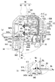
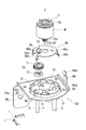
- FIG. 9 is an exploded perspective view of the lower cover member 80, the valve unit 70, the base member 86, and the motor M in the valve driving device 1.
- the valve unit 70 of the valve drive device 1 is a member that is driven to rotate around an axis X2 (see FIG. 9) in the central axis direction of a shaft member 73 having a rod-like cross section, which will be described later, by a motor M. 72.
- the gear 71 is an external gear that meshes with a tooth portion 33 c provided on the outer periphery of the transmission shaft 33 of the motor M.
- the valve body 72 is a member having a substantially disk shape. A circular hole is formed at the center of the valve body 72, and a notch is formed on the bottom surface of the valve body 72. A portion of the bottom surface of the valve body 72 where no notch is formed is configured to be able to close the openings 3a and 4a (see FIG. 9) of the fluid outlet tubes 3 and 4.
- the connecting member 15 is provided by being fitted into a through hole 10 c provided in the bottom plate portion 10 from the lower side opposite to the motor M (the fluid outlet pipes 3 and 4).
- a hole 15a for supporting a shaft member 73 which is a rod-like member having a substantially circular cross-sectional shape in the axial direction, is formed in the center of the connection member 15 so as to open to the fluid chamber S side.
- the opening 3a of the fluid outlet tube 3 and the opening 4a of the fluid outlet tube 4 are located at a position radially outside the hole 15a (see FIG. 9).
- the fluid outlet pipes 3 and 4 are respectively provided so as to penetrate the connecting member 15 in the axis X direction, and communicate with a fluid chamber S formed above the bottom plate portion 10 (toward the rotor 30).
- a through hole 10d is provided at a position opposite to the through hole 10c across the central hole portion 10a, and the fluid introduction pipe 2 is fitted into the through hole 10d.
- the opening 2 a of the fluid introduction pipe 2 is opened in the fluid chamber S, and the fluid introduction pipe 2 is communicated with the fluid chamber S.
- a base member 86 is placed on the upper surface 10 b (see FIG. 1) of the bottom plate portion 10, and the base member 86 is below the peripheral portion of the base portion 87 and the base portion 87. And a plurality of legs 88 (88a, 88b) extending to the side (fluid outlet pipes 3, 4 side).
- a hole portion 87a through which the transmission shaft 33 is inserted is formed in the central portion thereof, and an arm portion 89 including a support hole 89a is formed around the axis X on the radially outer side of the hole portion 87a.
- the bottom plate portion 10 when the partition wall 20 is fixed to the bottom plate portion 10, the bottom plate portion 10 reaches a position where the disk portion 203 of the partition wall 20 contacts the base portion 87 and the leg portion 88 a contacts the bottom plate portion 10. It pushes into the lower side (the fluid outlet pipes 3 and 4). At this time, since the leg portion 88b is provided so as to protrude radially outward from the leg portion 88a, the base member 86 is in a state in which the leg portion 88b is pressed against the inner periphery of the large-diameter portion 202 of the partition wall 20. It is held in the partition wall 20.
- the arm portion 89 can be deformed in the axial direction independently of the pedestal portion 87, and when the pedestal member 86 is pushed downward (toward the fluid outlet pipes 3 and 4) on the bottom plate portion 10 side.
- the valve body 72 is biased downward (toward the fluid outlet pipes 3 and 4) on the bottom plate 10 side.
- the support hole 89 a of the arm portion 89 is positioned by being fitted around the shaft member 73 of the valve portion 70. Therefore, the valve body 72 of the valve portion 70 is always brought into contact with the upper surface of the bottom plate portion 10 (the surface on the rotor 30 side) by the arm portion 89 and is positioned in the axial direction.
- a lower cover member 80 is externally fixed to the large diameter portion 202 of the partition wall 20 fixed to the upper surface (the surface on the rotor 30 side) of the bottom plate portion 10.
- the lower cover member 80 is provided with an opening 81a into which the large-diameter portion 202 of the partition wall 20 is inserted at the center of the plate-like base portion 81.
- the inner periphery of the opening 81a faces upward in the axis X direction.
- a plurality of erected contact pieces 81b are provided in the circumferential direction around the axis X.
- Each of the contact pieces 81b is provided so as to bulge from the opening 81a toward the axis X, and can be elastically deformed radially outward of the axis X. Therefore, when the lower cover member 80 is attached to the large-diameter portion 202 of the partition wall 20 by being extrapolated, the large-diameter portion 202 is inserted into the opening 81a of the base 81 while spreading the contact piece 81b radially outward. The lower cover member 80 is fixed to the partition wall 20.
- a mounting portion 85 formed by bending toward the lower side in the axis X direction (the fluid outlet pipes 3 and 4 side) is provided on one side in the width direction of the base portion 81.
- the attachment portion 85 is provided to attach the valve driving device 1 to a refrigerator that is an external structure, and is provided over the entire length of the base portion 81 in the longitudinal direction.
- the attachment portion 85 is formed with a hole portion 85a through which a screw or the like is inserted.
- the hole 85a is formed in the radial direction of the axis X in FIG. It is located radially outside the fluid outlet tube 3.
- reinforcing walls 82 and 83 formed by bending toward the upper side in the axis X direction are provided on both sides in the longitudinal direction of the base portion 81.
- the reinforcing walls 82 and 83 are provided over the entire length of the base 81 in the width direction, and the upper cover member 90 (see FIG. 3) is placed on the upper ends 82a and 83a of the reinforcing walls. ing.
- the coil terminal 56 is positioned above the reinforcing wall 82 on one side (the cover member 90), and on the reinforcing wall 83 on the other side.
- An engaging arm 84 for holding the lower cover member 80 and the upper cover member 90 in an engaged state is provided.
- the engaging arm 84 is provided so as to extend from a substantially central portion in the width direction in a direction away from the base 81 (upward), and on the upper end side of the engaging arm 84 swells toward the axis X side.
- An engaging portion 84a is provided. The engaging portion 84a is adapted to engage with the engaged portion 922 of the upper cover member 90 when the upper cover member 90 is attached by being extrapolated to the outer stator core 59 of the motor M. The falling of the cover member 90 from the lower cover member 80 is prevented.
- the reinforcing walls 82 and 83 are bent in the direction (upward) opposite to the bending direction (downward) of the attachment portion 85 in the axial direction of the axis X.
- the bending rigidity of the base portion 81 of 80 is increased. This is because when the lower cover member 80 is attached to the large-diameter portion 202 of the partition wall 20 by extrapolation (press-fit), the large-diameter portion 202 pushes the contact piece 81b outward in the radial direction, and the opening 81a of the base 81 is opened.
- the lower cover member 80 is inserted into the partition wall 20 and is fixed to the partition wall 20, so that the base 81 is not greatly deformed by the stress at this time.
- the reinforcing walls 82 and 83 on both sides in the longitudinal direction are bent in the same upward direction, the reinforcing walls 82 and 83 and the mounting portion 85 are connected by bending.
- the forming process can be performed more easily than when the reinforcing walls 82 and 83 are bent in different directions (vertical directions) in the axial direction of the axis X.
- the coil terminal 56 extending from the stator assembly 40 (stator) surrounding the rotor 30 is connected to the connector terminal 61 supported by the resin-made terminal support portion 940 and has a flexible plate-like substrate 60 (wiring member). Connected through At the connection portion (other end portion 60 b) between the connector terminal 61 and the substrate 60, the connector terminal 61 protruding from the terminal support portion 940 passes through the substrate 60 brought into contact with the terminal support portion 940, and supports the terminal on the substrate 60. In the motor connected to the surface opposite to the portion 940 by soldering, an insulating heat insulating member 946 is provided between the terminal support portion 940 and the substrate 60.
- the insulating heat insulation member 946 is provided between the terminal support part 940 and the board
- a resin upper cover member 90 (main body cover) having a peripheral wall portion 92 (peripheral wall) surrounding the outer periphery of the stator assembly 40 is formed of a resin connector cover portion 93 (connector) positioned on the radially outer side of the peripheral wall portion 92.
- the terminal support portion 940 is formed integrally with the connector cover portion 93.
- the terminal support portion 940 In order to prevent the terminal support portion 940 from being melted due to the influence of soldering heat, when the terminal support portion 940 is made of a heat resistant material, the terminal support portion 940 is connected to the upper cover member 90 and the connector cover portion 93. If they are integrally formed, they must also be made of a heat-resistant material. If comprised as mentioned above, since it is not necessary to comprise the terminal support part 940 with a heat resistant material, the upper cover member 90 and the connector cover part 93 which originally do not require heat resistance are formed with heat resistant resin. There is no need. Therefore, the degree of freedom of the resin material is improved, and the production cost necessary for providing heat resistance is not increased.
- the peripheral wall portion 92 is provided with an opening 92a that allows the inside of the cover portion 91 and the inside of the connector cover portion 93 to communicate with each other, and the coil extends outward in the radial direction of the stator assembly 40 through the opening 92a.
- the terminal 56 is connected to the connector terminal 61 that extends in the rotation axis direction (axis X direction) of the rotor 30 inside the connector cover portion 93 via the substrate 60, and the connector cover portion 93 has the diameter of the substrate 60.
- the edge 940c (side surface) is visible.
- substrate 60 will protrude in the opening 930 of the connector cover part 93, and the heat insulation member 946 can be easily attached to the support surface 940b. it can.
- the heat insulating member 946 is separately provided, the work cost is expected to increase. However, since the heat insulating member 946 can be easily attached, the increase in the work cost can be suppressed.
- a cap 96 that closes the opening 930 is detachably provided in the connector cover portion 93, and the opening 930 in the connector cover portion 93 opens outside in the radial direction of the opening 92 a provided in the peripheral wall portion 92.
- the outer peripheral direction of the coil terminal 56, the connector terminal 61, and the substrate 60 is covered by the peripheral wall portion 92, the connector cover portion 93, and the cap 96.
- connection portion between the substrate 60 and the coil terminal 56 and the connector terminal 61 is visible in the opening 930, the connection work by soldering the substrate 60 to the coil terminal 56 and the connector terminal 61 is performed. It can be done easily.
- An inner wall portion 944 (wall portion) extending in the rotation axis direction along the connector terminal 61 is provided on the inner diameter side of the terminal support portion 940, and the inner wall portion 944 is more than the coil terminal 56 when viewed from the rotation axis direction.
- a gap through which the coil terminal 56 passes is formed on the inner diameter side of the inner wall portion 944 inside the connector cover portion 93. .
- a gap is provided on the inner diameter side of the inner wall portion 944 so that the coil terminal 56 and the inner wall portion 944 do not overlap each other when viewed from the axial direction of the stator assembly 40.
- the coil terminal 56 extending radially outward from the stator assembly 40 does not interfere with the inner wall portion 944. Therefore, the upper cover member 90 and the stator assembly 40 can be reliably assembled.
- the coil terminal 56 and the connector terminal 61 are connected via a curved substrate 60, and a gap on the inner diameter side of the inner wall portion 944 is connected to the coil terminal 56 at one end side in the longitudinal direction. Forming the connected substrate 60 so that it can pass through;
- the inner wall portion 944 is provided with a notch 944a, and the inner edge of the terminal support portion 940 (inclined surface 940a) is exposed in the notch 944a.
- the board 60 connected to the coil terminal 56 is curved radially outward so that the other end 60b side of the board 60 is connected to the connector terminal. 61 will be connected.
- a notch portion 944a is provided in the inner wall portion 944 to expose the side edge on the inner diameter side of the terminal support portion 940, so that the space inside the connector cover portion 93 and on the inner diameter side of the terminal support portion 940 is increased. Therefore, when the board 60 is bent, the connection work with the connector terminal 61 of the board 60 can be easily performed.
- the radial width Wc of the heat insulating member 946 is narrower than the radial width Wd of the terminal support portion 940, and the inner side surface 946 b of the heat insulating member 946 is on the inner diameter side of the terminal support portion 940. It was set as the structure located in the predetermined direction We radial direction outer side rather than the side edge.
- the other end 60b side of the substrate 60 is curved radially outward, and the terminal hole 601 (see FIG. 3) provided in the other end 60b is used as a terminal support.
- the other end portion 60b of the substrate 60 is caught by the heat insulating member 946 and supported by the support surface 940b.
- the heat insulating member 946 that has been removed will come off. If comprised as mentioned above, since it can prevent suitably that the other end part 60b of the board
- connection portion between the substrate 60 and the connector terminal 61 and the connection portion between the substrate 60 and the coil terminal 56 are provided at positions offset in the rotation axis direction of the rotor 30 (the axial direction of the axis X). It was.
- the heat insulating member 946 is formed with a through hole 946a that penetrates in the thickness direction of the heat insulating member 946 and passes through the connector terminal 61, and is formed on one side of the substrate 60 (wiring member) in the thickness direction of the substrate 60.
- a terminal hole 601 that penetrates the connector terminal 61 is formed, and the inner diameter d1 of the through hole 946a formed in the heat insulating member 946 is larger than the outer diameter d2 of the land portion 601A of the terminal hole 601 formed in the substrate 60.
- the configuration is small (d1 ⁇ d2).
- the melting temperature of the heat insulating member 946 is higher than the melting temperature of the resin terminal support 940.
- the heat insulating member 946 can be prevented from being melted by the heat of soldering. Specifically, the heat insulating member 946 is melted by the heat of soldering to reduce the thickness, and the distance between the heat source for soldering and the terminal support portion 940 can be suitably prevented from melting the terminal support portion 940.
- the stator assembly 40 is further provided with a bobbin 53 and a drive coil 54 wound around the outer periphery of the bobbin 53, and an end portion of a winding drawn from the drive coil 54 is provided on the bobbin 53.
- the coil terminal 56 supported by the terminal holding portion 55A is configured to be soldered (entangled) at a position radially inward of the position where the substrate 60 and the coil terminal 56 are soldered.
- substrate 60 is The coil terminal 56 is always soldered at a position away from the terminal holding portion 55A by a certain distance.
- valve drive device of the present invention can be applied to a flow path for fluid other than the refrigerant of the refrigerator, and the structure for opening / closing the valve by the valve body 72 can be changed as appropriate.
Landscapes
- Engineering & Computer Science (AREA)
- Power Engineering (AREA)
- Motor Or Generator Frames (AREA)
- Insulation, Fastening Of Motor, Generator Windings (AREA)
Abstract
A motor in which coil terminals (56) extending from a stator assembly (40) (stator) surrounding a rotor (30) are connected, via a flexible plate-like substrate (60) (wiring member), to a connector terminal (61) supported by a terminal support part (940) made from a resin, and in which the connector terminal (61) protruding from the terminal support part (940) penetrates the substrate (60) that comes into contact with the terminal support part (940) and connects, by being soldered, to the surface of the substrate (60) on the opposite side of the terminal support part (940) at a connection part (other end part (60b)) of the connector terminal (61) and the substrate (60), wherein an insulating heat-insulation member (946) is disposed between the terminal support part (940) and the substrate (60).
Description
本発明は、モータに関する。
The present invention relates to a motor.
特許文献1には、モータのステータ構造が開示されている。
Patent Document 1 discloses a stator structure of a motor.
この特許文献1に開示されたモータのステータ構造では、ステータアッセンブリを収容する樹脂製のカバーを採用している。このカバーは、ステータアッセンブリの外周を囲む周壁部を有しており、この周壁部には、コネクタを覆う樹脂製のコネクタカバーが一体に形成されている。
カバーの内側とコネクタカバーの内側は、周壁部に設けた開口部を介して連通しており、ステータアッセンブリから径方向に延びる複数のコイル端子は、コネクタカバーの内側で、可撓性を有する基板を介して、対応するコネクタ端子に接続されている。 In the stator structure of the motor disclosed inPatent Document 1, a resin cover that accommodates the stator assembly is employed. The cover has a peripheral wall portion surrounding the outer periphery of the stator assembly, and a resin connector cover for covering the connector is integrally formed on the peripheral wall portion.
The inner side of the cover and the inner side of the connector cover communicate with each other through an opening provided in the peripheral wall portion, and the plurality of coil terminals extending in the radial direction from the stator assembly are flexible boards on the inner side of the connector cover. Are connected to the corresponding connector terminals.
カバーの内側とコネクタカバーの内側は、周壁部に設けた開口部を介して連通しており、ステータアッセンブリから径方向に延びる複数のコイル端子は、コネクタカバーの内側で、可撓性を有する基板を介して、対応するコネクタ端子に接続されている。 In the stator structure of the motor disclosed in
The inner side of the cover and the inner side of the connector cover communicate with each other through an opening provided in the peripheral wall portion, and the plurality of coil terminals extending in the radial direction from the stator assembly are flexible boards on the inner side of the connector cover. Are connected to the corresponding connector terminals.
コネクタカバーの内側には、コネクタ端子を支持する樹脂製の支持部材が配置されており、基板におけるコネクタ端子との接続部は、この支持部材に接触した状態で、半田付けにより、コネクタ端子に接続されるようになっている。
A resin support member that supports the connector terminal is arranged inside the connector cover, and the connection portion with the connector terminal on the board is connected to the connector terminal by soldering while in contact with the support member. It has come to be.
ここで、支持部材の材質によっては、半田付けを行う際の熱により支持部材が熔解する虞があり、かかる場合には、支持部材におけるコネクタ端子の支持強度が低下してしまう。
Here, depending on the material of the support member, the support member may be melted by heat during soldering. In such a case, the support strength of the connector terminal in the support member is reduced.
そこで、コネクタ端子と基板とを半田付けで接続する際に、半田付けの熱の影響が、支持部材に及ばないようにすることが求められている。
Therefore, when connecting the connector terminal and the board by soldering, it is required to prevent the heat of soldering from affecting the support member.
本発明は、
ロータを囲むステータから延びるコイル端子が、樹脂製の端子支持部で支持されたコネクタ端子に、可撓性を有する板状の配線部材を介して接続され、コネクタ端子と配線部材との接続部では、端子支持部から突出するコネクタ端子が、端子支持部に接触させた配線部材を貫通して、配線部材の端子支持部とは反対側の面に半田付けにより接続されたモータにおいて、端子支持部と配線部材との間に、絶縁性の断熱部材を設けた構成のモータとした。 The present invention
A coil terminal extending from the stator surrounding the rotor is connected to a connector terminal supported by a resin-made terminal support portion via a flexible plate-like wiring member, and at the connection portion between the connector terminal and the wiring member, In the motor in which the connector terminal protruding from the terminal support portion passes through the wiring member brought into contact with the terminal support portion and is connected to the surface opposite to the terminal support portion of the wiring member by soldering, the terminal support portion The motor has a configuration in which an insulating heat insulating member is provided between the wiring member and the wiring member.
本発明によれば、端子支持部と配線部材との間に絶縁性の断熱部材が設けられているので、コネクタ端子と配線部材とを接続する際の半田付けの熱の影響が、端子支持部に及ぶことを好適に防止できる。
According to the present invention, since the insulating heat insulating member is provided between the terminal support portion and the wiring member, the influence of the soldering heat when connecting the connector terminal and the wiring member is affected by the terminal support portion. Can be suitably prevented.
以下、本発明の実施形態について、本発明を、冷蔵庫の冷媒の流路を開閉する弁装置のバルブ駆動装置(ギアユニット)に適用した場合を例に挙げて、適宜図面を参照しながら詳細に説明する。
なお、各図において、共通する部分には同一の符号を付して示すと共に重複した説明を省略する。
以下の説明では、図1に示したバルブ駆動装置1のロータ30の回転軸の軸線Xを基準として、軸線Xの軸方向におけるロータ30側を上方、流体導出管3、4側を下方として、バルブ駆動装置の各構成要素の位置関係を適宜説明する。 Hereinafter, embodiments of the present invention will be described in detail with reference to the drawings as appropriate, taking as an example the case where the present invention is applied to a valve drive device (gear unit) of a valve device that opens and closes a refrigerant flow path of a refrigerator. explain.
In addition, in each figure, the common code | symbol is attached | subjected and shown, and the overlapping description is abbreviate | omitted.
In the following description, with reference to the axis X of the rotation axis of therotor 30 of the valve drive device 1 shown in FIG. 1, the rotor 30 side in the axial direction of the axis X is the upper side, and the fluid outlet pipes 3 and 4 are the lower side. The positional relationship of each component of the valve driving device will be described as appropriate.
なお、各図において、共通する部分には同一の符号を付して示すと共に重複した説明を省略する。
以下の説明では、図1に示したバルブ駆動装置1のロータ30の回転軸の軸線Xを基準として、軸線Xの軸方向におけるロータ30側を上方、流体導出管3、4側を下方として、バルブ駆動装置の各構成要素の位置関係を適宜説明する。 Hereinafter, embodiments of the present invention will be described in detail with reference to the drawings as appropriate, taking as an example the case where the present invention is applied to a valve drive device (gear unit) of a valve device that opens and closes a refrigerant flow path of a refrigerator. explain.
In addition, in each figure, the common code | symbol is attached | subjected and shown, and the overlapping description is abbreviate | omitted.
In the following description, with reference to the axis X of the rotation axis of the
図1は、実施形態にかかるバルブ駆動装置1の断面図である。図2は、図1におけるX1-X1断面図である。図3は、バルブ駆動装置1のモータM側の分解斜視図である。
なお、図3では、ステータアッセンブリ40における樹脂で形成された部分をハッチングして示している。 FIG. 1 is a cross-sectional view of avalve drive device 1 according to an embodiment. 2 is a cross-sectional view taken along line X1-X1 in FIG. FIG. 3 is an exploded perspective view of the valve drive device 1 on the motor M side.
In FIG. 3, a portion of thestator assembly 40 formed of resin is hatched.
なお、図3では、ステータアッセンブリ40における樹脂で形成された部分をハッチングして示している。 FIG. 1 is a cross-sectional view of a
In FIG. 3, a portion of the
図1から図3に示すように、本発明の実施形態にかかるバルブ駆動装置1は、外部装置である冷蔵庫(図示せず)との間に流体(ここでは、冷媒)が循環可能な流路を構成し、冷蔵庫から流体導入管2を介して流体室S内へ導入された流体を、流体導出管3、4を介して冷蔵庫へ導出する弁装置である。
このバルブ駆動装置1では、モータMにより弁部70を駆動して、流体室S内に導入された流体を、流体導出管3、4から冷蔵庫側に導出するようになっており、このバルブ駆動装置1のモータMとして、一対のステータ組50A、50B(A相のコイルとB相のコイル)がロータ30の回転軸の軸線X方向に並べて配置されたクローポール型ステッピングモータが採用されている。 As shown in FIGS. 1 to 3, thevalve drive device 1 according to the embodiment of the present invention is a flow path through which fluid (here, refrigerant) can circulate between a refrigerator (not shown) that is an external device. , And is a valve device that guides the fluid introduced from the refrigerator into the fluid chamber S through the fluid introduction pipe 2 to the refrigerator through the fluid outlet pipes 3 and 4.
In thisvalve drive device 1, the valve portion 70 is driven by the motor M, and the fluid introduced into the fluid chamber S is led out from the fluid outlet pipes 3 and 4 to the refrigerator side. As the motor M of the apparatus 1, a claw pole type stepping motor in which a pair of stator sets 50 </ b> A and 50 </ b> B (A phase coil and B phase coil) are arranged in the direction of the axis X of the rotation axis of the rotor 30 is employed. .
このバルブ駆動装置1では、モータMにより弁部70を駆動して、流体室S内に導入された流体を、流体導出管3、4から冷蔵庫側に導出するようになっており、このバルブ駆動装置1のモータMとして、一対のステータ組50A、50B(A相のコイルとB相のコイル)がロータ30の回転軸の軸線X方向に並べて配置されたクローポール型ステッピングモータが採用されている。 As shown in FIGS. 1 to 3, the
In this
バルブ駆動装置1では、底板部10の上面(ロータ30側の面)に固定した有底円筒形状の隔壁20により、底板部10と隔壁20の間に流体室Sが形成されている。
バルブ駆動装置1において隔壁20は、底部20aを底板部10とは反対側の上方(ロータ30側の方)に向けて設けられている。隔壁20は、底部20aから離れる方向で2段に拡径した外形を有しており、底部20a側の小径部201と、底板部10側の大径部202と、を備えて構成される。
底板部10の外周縁には、大径部202の先端202aが外嵌する段部11が、全周に亘って設けられており、隔壁20は、大径部202の先端202aを段部11に嵌合させて、底板部10に固定されている。
また、バルブ駆動装置1は、モータMのロータ30を上側、流体室Sを下側に向けた配置(図1参照)で使用されるようになっている。 In thevalve driving device 1, a fluid chamber S is formed between the bottom plate portion 10 and the partition wall 20 by a bottomed cylindrical partition wall 20 fixed to the upper surface (the surface on the rotor 30 side) of the bottom plate portion 10.
In thevalve drive device 1, the partition wall 20 is provided with the bottom portion 20 a facing upward (on the rotor 30 side) opposite to the bottom plate portion 10. The partition wall 20 has an outer shape expanded in two steps in a direction away from the bottom portion 20a, and includes a small diameter portion 201 on the bottom portion 20a side and a large diameter portion 202 on the bottom plate portion 10 side.
On the outer peripheral edge of thebottom plate portion 10, a stepped portion 11 is provided over the entire periphery to which the tip end 202 a of the large diameter portion 202 is fitted, and the partition wall 20 has the tip end 202 a of the large diameter portion 202 on the stepped portion 11. And is fixed to the bottom plate portion 10.
Further, thevalve drive device 1 is used in an arrangement (see FIG. 1) in which the rotor 30 of the motor M is directed upward and the fluid chamber S is directed downward.
バルブ駆動装置1において隔壁20は、底部20aを底板部10とは反対側の上方(ロータ30側の方)に向けて設けられている。隔壁20は、底部20aから離れる方向で2段に拡径した外形を有しており、底部20a側の小径部201と、底板部10側の大径部202と、を備えて構成される。
底板部10の外周縁には、大径部202の先端202aが外嵌する段部11が、全周に亘って設けられており、隔壁20は、大径部202の先端202aを段部11に嵌合させて、底板部10に固定されている。
また、バルブ駆動装置1は、モータMのロータ30を上側、流体室Sを下側に向けた配置(図1参照)で使用されるようになっている。 In the
In the
On the outer peripheral edge of the
Further, the
小径部201の内側には、モータMのロータ30が、軸部材21に外挿された状態で設けられている。
バルブ駆動装置1において軸部材21は、ロータ30における回転軸の軸線Xに沿って設けられており、この軸部材21の一端21aは、底部20aの凹部20bで支持されており、他端21bは、底板部10の孔部10aでロウ付けされており、軸部材21は、回り止めされた状態で設けられている。
軸部材21においてロータ30は、回転可能に支持されており、モータMの駆動時に、軸線X周りに回転するようになっている。 Inside thesmall diameter portion 201, the rotor 30 of the motor M is provided in a state of being extrapolated to the shaft member 21.
In thevalve drive device 1, the shaft member 21 is provided along the axis X of the rotation shaft of the rotor 30, one end 21 a of the shaft member 21 is supported by the recess 20 b of the bottom portion 20 a, and the other end 21 b is The shaft member 21 is brazed at the hole 10a of the bottom plate portion 10 and is prevented from rotating.
In theshaft member 21, the rotor 30 is rotatably supported, and rotates around the axis X when the motor M is driven.
バルブ駆動装置1において軸部材21は、ロータ30における回転軸の軸線Xに沿って設けられており、この軸部材21の一端21aは、底部20aの凹部20bで支持されており、他端21bは、底板部10の孔部10aでロウ付けされており、軸部材21は、回り止めされた状態で設けられている。
軸部材21においてロータ30は、回転可能に支持されており、モータMの駆動時に、軸線X周りに回転するようになっている。 Inside the
In the
In the
ロータ30は、軸部材21に外挿される軸受部31aを有する基部31と、軸線X周りの周方向でN相とS相とが交互に配置された磁石32と、を備えて構成される。
磁石32は、ロータ30を樹脂成形する際に、インサート成型により基部31と一体に形成されており、基部31において磁石32は、軸線X周りの周方向で全周に亘って設けられている。 Therotor 30 includes a base portion 31 having a bearing portion 31 a that is extrapolated to the shaft member 21, and magnets 32 in which N and S phases are alternately arranged in the circumferential direction around the axis X.
When therotor 30 is resin-molded, the magnet 32 is formed integrally with the base 31 by insert molding. In the base 31, the magnet 32 is provided over the entire circumference in the circumferential direction around the axis X.
磁石32は、ロータ30を樹脂成形する際に、インサート成型により基部31と一体に形成されており、基部31において磁石32は、軸線X周りの周方向で全周に亘って設けられている。 The
When the
基部31の底板部10側の下部には、ロータ30の回転を後記する弁部70に伝達する伝達軸33が、軸受部31aと基部31の間に挿入されて固定されている。伝達軸33は、ロータ30と同様に、軸部材21に回転可能に支持されており、ロータ30と一体に軸線X周りに回転するようになっている。
A transmission shaft 33 that transmits the rotation of the rotor 30 to a valve portion 70 described later is inserted between the bearing portion 31 a and the base portion 31 and fixed to the lower portion of the base portion 31 on the bottom plate portion 10 side. Like the rotor 30, the transmission shaft 33 is rotatably supported by the shaft member 21, and rotates around the axis line X integrally with the rotor 30.
伝達軸33は、軸線Xに沿って底板部10側の下方に延びており、その先端部33aを、底板部10の上面10bに当接させている。
実施の形態においてロータ30は、軸部材21の一端21a側に外挿したスプリングSpにより、底板部10側の下方に付勢されており、このスプリングSpの付勢力により、伝達軸33の先端部33aが、底板部10の上面10bに常時当接させられて、ロータ30の軸線Xの軸方向の位置決めがされている。 Thetransmission shaft 33 extends downward along the axis X on the side of the bottom plate portion 10, and the tip end portion 33 a is in contact with the upper surface 10 b of the bottom plate portion 10.
In the embodiment, therotor 30 is urged downward on the bottom plate portion 10 side by a spring Sp extrapolated to the one end 21a side of the shaft member 21, and the tip portion of the transmission shaft 33 is urged by the urging force of the spring Sp. 33a is always brought into contact with the upper surface 10b of the bottom plate portion 10, and the axial line X of the rotor 30 is positioned in the axial direction.
実施の形態においてロータ30は、軸部材21の一端21a側に外挿したスプリングSpにより、底板部10側の下方に付勢されており、このスプリングSpの付勢力により、伝達軸33の先端部33aが、底板部10の上面10bに常時当接させられて、ロータ30の軸線Xの軸方向の位置決めがされている。 The
In the embodiment, the
伝達軸33における先端部33aの上側(ロータ30側)は、当該先端部33aよりも径が大きい大径部33bとなっており、この大径部33bの外周には、後記するギヤ71の外周に設けた歯部71gに噛合する歯部33cが設けられている(図2参照)。
An upper side (rotor 30 side) of the distal end portion 33a of the transmission shaft 33 is a large diameter portion 33b having a diameter larger than that of the distal end portion 33a, and an outer periphery of a gear 71 described later is provided on the outer periphery of the large diameter portion 33b. The tooth part 33c which meshes with the tooth part 71g provided in is provided (see FIG. 2).
図2に示すように、ロータ30を収容する隔壁20の小径部201は、ロータ30の磁石32を所定間隔で囲む筒状に形成されており、この小径部201の外周には、ステータアッセンブリ40が外挿されて取り付けられている。
実施の形態では、小径部201と大径部202を接続する円板部203が、軸線Xに直交して設けられており、この円板部203により、小径部201に外挿したステータアッセンブリ40の位置決めがされて、ロータ30(磁石32)の径方向外側に、2つのステータ組50A、50Bが配置されるようになっている。
なお、ロータ30の磁石32は、隔壁20を介して後述のステータアッセンブリ40からの磁力によって駆動されるため、隔壁20は非磁性体で構成される。また流体室Sの圧力に耐えられるよう、隔壁20は金属で構成される。このため、隔壁20は非磁性金属であるステンレスで構成される。 As shown in FIG. 2, the small-diameter portion 201 of the partition wall 20 that accommodates the rotor 30 is formed in a cylindrical shape that surrounds the magnet 32 of the rotor 30 at a predetermined interval, and the stator assembly 40 is disposed on the outer periphery of the small-diameter portion 201. Is attached by extrapolation.
In the embodiment, thedisk portion 203 that connects the small diameter portion 201 and the large diameter portion 202 is provided orthogonal to the axis X, and the stator assembly 40 extrapolated to the small diameter portion 201 by the disk portion 203. The two stator sets 50A and 50B are arranged on the radially outer side of the rotor 30 (magnet 32).
Since themagnet 32 of the rotor 30 is driven by a magnetic force from a stator assembly 40 described later via the partition wall 20, the partition wall 20 is made of a nonmagnetic material. Further, the partition wall 20 is made of metal so as to withstand the pressure of the fluid chamber S. For this reason, the partition 20 is comprised with the stainless steel which is a nonmagnetic metal.
実施の形態では、小径部201と大径部202を接続する円板部203が、軸線Xに直交して設けられており、この円板部203により、小径部201に外挿したステータアッセンブリ40の位置決めがされて、ロータ30(磁石32)の径方向外側に、2つのステータ組50A、50Bが配置されるようになっている。
なお、ロータ30の磁石32は、隔壁20を介して後述のステータアッセンブリ40からの磁力によって駆動されるため、隔壁20は非磁性体で構成される。また流体室Sの圧力に耐えられるよう、隔壁20は金属で構成される。このため、隔壁20は非磁性金属であるステンレスで構成される。 As shown in FIG. 2, the small-
In the embodiment, the
Since the
図2に示すように、ステータアッセンブリ40は、軸線Xの軸方向に重ねて配置された2つのステータ組50A、50Bを備えており、このステータアッセンブリ40には、ステータ組50A、50Bの外周を囲む外ステータコア59が外挿して取り付けられている。
外ステータコア59は、後記する内ステータコア51、52と同様に、磁性体の板体をプレス加工することで形成されており、ステータ組50A、50Bに外挿して取り付けた際に、外ステータコア59と内ステータコア51、52とが互いに接触した状態で設けられて、外ステータコア59と内ステータコア51、52とで磁路が構成されるようになっている。 As shown in FIG. 2, thestator assembly 40 includes two stator sets 50A and 50B arranged so as to overlap each other in the axial direction of the axis X, and the stator assembly 40 has outer peripheries of the stator sets 50A and 50B. A surrounding outer stator core 59 is attached by extrapolation.
Theouter stator core 59 is formed by pressing a magnetic plate like the inner stator cores 51 and 52 to be described later. When the outer stator core 59 is attached to the stator assemblies 50A and 50B, the outer stator core 59 and The inner stator cores 51 and 52 are provided in contact with each other, and the outer stator core 59 and the inner stator cores 51 and 52 constitute a magnetic path.
外ステータコア59は、後記する内ステータコア51、52と同様に、磁性体の板体をプレス加工することで形成されており、ステータ組50A、50Bに外挿して取り付けた際に、外ステータコア59と内ステータコア51、52とが互いに接触した状態で設けられて、外ステータコア59と内ステータコア51、52とで磁路が構成されるようになっている。 As shown in FIG. 2, the
The
ステータ組50A、50Bの各々は、軸方向に間隔をあけて配置された一対の内ステータコア51、52の間に、ボビン53の外周に巻き付けられた駆動コイル54を配置した基本構成を有している。
ステータアッセンブリ40においてボビン53は、その内部にステータ組50A、50Bの内ステータコア51、52がインサート成形により埋め込まれた樹脂成形体(絶縁体)であり、後記する端子保持部55と一体に形成されている。 Each of the stator sets 50A and 50B has a basic configuration in which adrive coil 54 wound around the outer periphery of a bobbin 53 is disposed between a pair of inner stator cores 51 and 52 that are spaced apart in the axial direction. Yes.
In thestator assembly 40, the bobbin 53 is a resin molded body (insulator) in which the inner stator cores 51 and 52 of the stator assemblies 50A and 50B are embedded by insert molding, and is formed integrally with a terminal holding portion 55 described later. ing.
ステータアッセンブリ40においてボビン53は、その内部にステータ組50A、50Bの内ステータコア51、52がインサート成形により埋め込まれた樹脂成形体(絶縁体)であり、後記する端子保持部55と一体に形成されている。 Each of the stator sets 50A and 50B has a basic configuration in which a
In the
図4の(a)は、図1における要部を拡大した断面図であり、(b)は、(a)における領域Aの拡大図である。
図4に示すように、内ステータコア51、52は、軸線Xに直交する向きで配置されたリング状のフランジ部510、520と、フランジ部510、520の内周から軸線X方向に起立形成された複数の極歯511、521とを備えており、フランジ部510、520の内径側において極歯511、521は、軸線X周りの周方向に等間隔で設けられている。
ステータ組50A、50Bの一対の内ステータコア51、52は、一方の内ステータコア51の極歯511と、他方の内ステータコア52の極歯521とが、軸線X周りの周方向で交互に並んで配置されるように、互いの極歯511、521を対向させる向きで配置されている。 4A is an enlarged cross-sectional view of the main part in FIG. 1, and FIG. 4B is an enlarged view of a region A in FIG.
As shown in FIG. 4, the inner stator cores 51 and 52 are formed to stand in the axis X direction from the inner periphery of the ring-shaped flange portions 510 and 520 arranged in a direction orthogonal to the axis X and the flange portions 510 and 520. The pole teeth 511 and 521 are provided at equal intervals in the circumferential direction around the axis X on the inner diameter side of the flange portions 510 and 520.
The pair of inner stator cores 51 and 52 of the stator sets 50A and 50B are arranged such that the pole teeth 511 of one inner stator core 51 and the pole teeth 521 of the other inner stator core 52 are alternately arranged in the circumferential direction around the axis X. As shown in the figure, the pole teeth 511 and 521 are arranged to face each other.
図4に示すように、内ステータコア51、52は、軸線Xに直交する向きで配置されたリング状のフランジ部510、520と、フランジ部510、520の内周から軸線X方向に起立形成された複数の極歯511、521とを備えており、フランジ部510、520の内径側において極歯511、521は、軸線X周りの周方向に等間隔で設けられている。
ステータ組50A、50Bの一対の内ステータコア51、52は、一方の内ステータコア51の極歯511と、他方の内ステータコア52の極歯521とが、軸線X周りの周方向で交互に並んで配置されるように、互いの極歯511、521を対向させる向きで配置されている。 4A is an enlarged cross-sectional view of the main part in FIG. 1, and FIG. 4B is an enlarged view of a region A in FIG.
As shown in FIG. 4, the
The pair of
極歯511、521の径方向外側には、外周にコイルが巻き付けられたボビン53の円筒状の基部530が位置しており、軸線Xの軸方向におけるこの基部530の両端には、径方向外側に延びる鍔部531、532が、軸線X周りの周方向で全周に亘って設けられている。
A cylindrical base portion 530 of a bobbin 53 around which a coil is wound is located on the outer side in the radial direction of the pole teeth 511 and 521, and the outer side in the radial direction is located at both ends of the base portion 530 in the axial direction of the axis X. The flanges 531 and 532 extending in the circumferential direction are provided over the entire circumference in the circumferential direction around the axis X.
図2に示すように、ステータアッセンブリ40において、ステータ組50Aの内ステータコア51と、ステータ組50Bの内ステータコア52は、軸線Xの軸方向で、フランジ部510、520(図4参照)同士を接触させた状態で設けられている。
そして、これらフランジ部510、520が隙間なく接合された状態で、樹脂内に保持されている。 As shown in FIG. 2, in thestator assembly 40, the inner stator core 51 of the stator assembly 50A and the inner stator core 52 of the stator assembly 50B are in contact with the flange portions 510 and 520 (see FIG. 4) in the axial direction of the axis X. It is provided in a state of letting it.
And these flange parts 510 and 520 are hold | maintained in resin in the state joined without gap.
そして、これらフランジ部510、520が隙間なく接合された状態で、樹脂内に保持されている。 As shown in FIG. 2, in the
And these
内ステータコア51、52が埋め込まれたステータアッセンブリ40では、ボビン53の基部530の内径側に極歯511、521が露出しており、フランジ部510、520の駆動コイル54側の面が、鍔部531、532を構成する樹脂で覆われている。
In the stator assembly 40 in which the inner stator cores 51 and 52 are embedded, the pole teeth 511 and 521 are exposed on the inner diameter side of the base portion 530 of the bobbin 53, and the surface of the flange portions 510 and 520 on the drive coil 54 side is the flange portion. 531 and 532 are covered with resin.
そして、ステータアッセンブリ40では、ステータ組50Bのフランジ部510の内径側の上面を覆う樹脂材料により、リング状の取付部57(図2、図3参照)が形成されており、この取付部57には、後記する上カバー部材90の嵌合壁91cが内嵌して取り付けられるようになっている。
また、ステータ組50Aのフランジ部520の内径側の下面を覆う樹脂材料により、リング状の当接部58(図2参照)が形成されている。この当接部58は、ステータアッセンブリ40が隔壁20の小径部201外挿された際に、小径部201と大径部202との境界の円板部203に軸線X方向から当接するようになっており、ステータアッセンブリ40の軸方向の位置決めが、円板部203に当接させた当接部58により行われるようになっている。 In thestator assembly 40, a ring-shaped attachment portion 57 (see FIGS. 2 and 3) is formed of a resin material that covers the upper surface on the inner diameter side of the flange portion 510 of the stator assembly 50B. Are fitted with a fitting wall 91c of an upper cover member 90 to be described later.
Further, a ring-shaped contact portion 58 (see FIG. 2) is formed of a resin material that covers the lower surface on the inner diameter side of theflange portion 520 of the stator assembly 50A. The contact portion 58 comes into contact with the disk portion 203 at the boundary between the small diameter portion 201 and the large diameter portion 202 from the axis X direction when the stator assembly 40 is extrapolated to the small diameter portion 201 of the partition wall 20. In addition, the positioning of the stator assembly 40 in the axial direction is performed by a contact portion 58 that is in contact with the disc portion 203.
また、ステータ組50Aのフランジ部520の内径側の下面を覆う樹脂材料により、リング状の当接部58(図2参照)が形成されている。この当接部58は、ステータアッセンブリ40が隔壁20の小径部201外挿された際に、小径部201と大径部202との境界の円板部203に軸線X方向から当接するようになっており、ステータアッセンブリ40の軸方向の位置決めが、円板部203に当接させた当接部58により行われるようになっている。 In the
Further, a ring-shaped contact portion 58 (see FIG. 2) is formed of a resin material that covers the lower surface on the inner diameter side of the
図4に示すように、各ステータコアのフランジ部510、520では、その外周部の一部に軸線X側に窪んだ切欠き部510b、520bが形成されており、各フランジ部510、520の切欠き部510b、520bは、軸線Xの軸方向から見て重なる位置に設けられている。実施の形態では、この切欠き部510b、520bの部分を利用して、端子保持部55が設けられている。
As shown in FIG. 4, in the flange portions 510 and 520 of each stator core, notches 510b and 520b that are recessed toward the axis X side are formed in a part of the outer peripheral portion, and the notches of the flange portions 510 and 520 are formed. The notches 510b and 520b are provided at positions overlapping when viewed from the axial direction of the axis X. In the embodiment, the terminal holding portion 55 is provided by using the notches 510b and 520b.
ステータ組50Bの端子保持部55Bは、フランジ部510、520の切欠き部510b、520bに跨って設けられている。
この端子保持部55Bは、フランジ部510、520の両側に位置するボビン53の鍔部532、531と一体に形成されており、軸線Xの軸方向に所定の厚みを有している。 Theterminal holding portion 55B of the stator assembly 50B is provided across the notches 510b and 520b of the flange portions 510 and 520.
Theterminal holding portion 55B is formed integrally with the flange portions 532 and 531 of the bobbin 53 located on both sides of the flange portions 510 and 520, and has a predetermined thickness in the axial direction of the axis X.
この端子保持部55Bは、フランジ部510、520の両側に位置するボビン53の鍔部532、531と一体に形成されており、軸線Xの軸方向に所定の厚みを有している。 The
The
ステータ組50Aの端子保持部55Aは、内ステータコア52のフランジ部520の切欠き部520bに設けられている。
この端子保持部55Aは、ステータ組50Aのボビン53の鍔部532と一体に形成されており、軸線Xの軸方向に所定の厚みを有している。 The terminal holding portion 55 </ b> A of the stator set 50 </ b> A is provided in thenotch portion 520 b of the flange portion 520 of the inner stator core 52.
Theterminal holding portion 55A is formed integrally with the flange portion 532 of the bobbin 53 of the stator assembly 50A, and has a predetermined thickness in the axial direction of the axis X.
この端子保持部55Aは、ステータ組50Aのボビン53の鍔部532と一体に形成されており、軸線Xの軸方向に所定の厚みを有している。 The terminal holding portion 55 </ b> A of the stator set 50 </ b> A is provided in the
The
ステータ組50Aの端子保持部55Aと、ステータ組50Bの端子保持部55Bは、軸線X方向に間隔をあけて設けられている。
ステータ組50A、50Bの端子保持部55A、55Bには、複数のコイル端子56が圧入されて支持されており、複数のコイル端子56は、ステータアッセンブリ40から径方向外側に突出して設けられていると共に、コイル端子56の基端は、切欠き部510b、520b内に位置している。 Theterminal holding portion 55A of the stator set 50A and the terminal holding portion 55B of the stator set 50B are provided with an interval in the axis X direction.
A plurality ofcoil terminals 56 are press-fitted and supported by the terminal holding portions 55A and 55B of the stator assemblies 50A and 50B, and the plurality of coil terminals 56 are provided so as to protrude radially outward from the stator assembly 40. At the same time, the base end of the coil terminal 56 is located in the notches 510b and 520b.
ステータ組50A、50Bの端子保持部55A、55Bには、複数のコイル端子56が圧入されて支持されており、複数のコイル端子56は、ステータアッセンブリ40から径方向外側に突出して設けられていると共に、コイル端子56の基端は、切欠き部510b、520b内に位置している。 The
A plurality of
そのため、ステータアッセンブリ40に外挿して取り付けられる外ステータコア59では、ステータ組50A、50Bの外周を囲む周壁部592に、コイル端子56との干渉を避けるための切欠き部593(図3参照)が設けられていると共に、後記する上カバー部材90の周壁部92にも、コイル端子56との干渉を避けるための開口部92aが設けられている(図1参照)。
For this reason, in the outer stator core 59 that is attached by being extrapolated to the stator assembly 40, a cutout portion 593 (see FIG. 3) for avoiding interference with the coil terminal 56 is formed on the peripheral wall portion 592 surrounding the outer periphery of the stator assemblies 50A and 50B. The opening 92a for avoiding interference with the coil terminal 56 is also provided in the peripheral wall 92 of the upper cover member 90 described later (see FIG. 1).
なお、外ステータコア59は、図3に示すように、有底円筒形状を有しており、底部591の中央部に、隔壁20の底部20a側を挿通可能とする開口591aが設けられている。そして、底部591の全周に亘って設けられた周壁部592は、ステータ組50A、50Bのフランジ部510、520を全周に亘って取り囲む円筒形状を成している。
As shown in FIG. 3, the outer stator core 59 has a bottomed cylindrical shape, and an opening 591 a through which the bottom 20 a side of the partition wall 20 can be inserted is provided at the center of the bottom 591. And the surrounding wall part 592 provided over the perimeter of the bottom part 591 has comprised the cylindrical shape which surrounds the flange parts 510 and 520 of stator assembly 50A, 50B over a perimeter.
図4に示すように、コイル端子56は、直線状に延びる棒形状を成す導電性のピンであり、上カバー部材90に設けた開口部92aを貫通して、その先端側を、コネクタカバー部93(収容部95)内に位置させている。
As shown in FIG. 4, the coil terminal 56 is a conductive pin having a linearly extending rod shape. The coil terminal 56 passes through an opening 92 a provided in the upper cover member 90, and the tip end side thereof is connected to the connector cover portion. 93 (accommodating portion 95).
実施の形態では、端子保持部55Aで保持されたコイル端子56の端子保持部55A側には、ステータ組50Aの駆動コイル54(A相のコイル)から引き出された巻き線の端部(図示せず)が絡げられ、端子保持部55Bで保持されたコイル端子56の端子保持部55B側には、ステータ組50Bの駆動コイル54(B相のコイル)から引き出された巻き線の端部(図示せず)が絡げられている。
そして、これら端子保持部55A、55Bで支持されたコイル端子56の各々は、ポリイミド樹脂から構成される可撓性を有する共通の基板60(以下、基板60とも表記する)を介して、それぞれ対応するコネクタ端子61に接続されている。なお、コイル端子56の各々は、基板60における駆動コイル54とは反対側の面で、基板60に設けられた配線のうちの対応する配線に、半田付けにより接続されている。 In the embodiment, on theterminal holding portion 55A side of the coil terminal 56 held by the terminal holding portion 55A, an end of a winding wire (not shown) drawn from the drive coil 54 (A phase coil) of the stator assembly 50A. And the end of the winding wire drawn from the drive coil 54 (B phase coil) of the stator assembly 50B on the terminal holding portion 55B side of the coil terminal 56 held by the terminal holding portion 55B. (Not shown).
Each of thecoil terminals 56 supported by the terminal holding portions 55A and 55B corresponds to each other via a flexible common substrate 60 (hereinafter also referred to as a substrate 60) made of polyimide resin. Connected to the connector terminal 61. Note that each of the coil terminals 56 is connected to a corresponding wiring among the wirings provided on the substrate 60 on the surface of the substrate 60 opposite to the drive coil 54 by soldering.
そして、これら端子保持部55A、55Bで支持されたコイル端子56の各々は、ポリイミド樹脂から構成される可撓性を有する共通の基板60(以下、基板60とも表記する)を介して、それぞれ対応するコネクタ端子61に接続されている。なお、コイル端子56の各々は、基板60における駆動コイル54とは反対側の面で、基板60に設けられた配線のうちの対応する配線に、半田付けにより接続されている。 In the embodiment, on the
Each of the
図1から図3に示すように、上カバー部材90は、モータMのステータアッセンブリ40と外ステータコア59を収容する部材であり、ステータアッセンブリ40の上面を覆うカバー部91と、外ステータコア59の外周を囲む周壁部92と、を有しており、周壁部92には、コネクタカバー部93が一体に形成されている。
なお、この上カバー部材90は、ポリカーボネートとABS樹脂の混合樹脂を樹脂成型することで形成される。 As shown in FIGS. 1 to 3, theupper cover member 90 is a member that accommodates the stator assembly 40 and the outer stator core 59 of the motor M. The upper cover member 90 covers the upper surface of the stator assembly 40, and the outer periphery of the outer stator core 59. And a peripheral wall portion 92 that surrounds the connector wall portion 92, and a connector cover portion 93 is formed integrally with the peripheral wall portion 92.
Theupper cover member 90 is formed by resin molding a mixed resin of polycarbonate and ABS resin.
なお、この上カバー部材90は、ポリカーボネートとABS樹脂の混合樹脂を樹脂成型することで形成される。 As shown in FIGS. 1 to 3, the
The
図5は、上カバー部材90のコネクタカバー部93を説明する図であり、(a)は、コネクタカバー部93のコネクタ部94と収容部95とを右斜め上方から見た斜視図であり、(b)は、コネクタ部94と収容部95とを斜め下方から見た斜視図であり、(c)は、収容部95を径方向から見た図である。
図6は、コネクタカバー部93を説明する図であり、(a)は、軸線X方向の上側から見た図であって、(b)は、斜視図であり、(c)は、コネクタカバー部93の端子支持部940に対する断熱部材946の取り付けを説明する図である。
図7は、コネクタ部94を説明する図であり、(a)は、軸線X方向の下側から見た図、(b)は、軸線X方向の斜め下側から見た斜視図である。 FIG. 5 is a diagram for explaining theconnector cover portion 93 of the upper cover member 90, and (a) is a perspective view of the connector portion 94 and the accommodating portion 95 of the connector cover portion 93 as viewed from the upper right side, (B) is the perspective view which looked at the connector part 94 and the accommodating part 95 from diagonally downward, (c) is the figure which looked at the accommodating part 95 from radial direction.
6A and 6B are diagrams illustrating theconnector cover portion 93, where FIG. 6A is a view seen from the upper side in the axis X direction, FIG. 6B is a perspective view, and FIG. 6C is a connector cover. It is a figure explaining attachment of the heat insulation member 946 with respect to the terminal support part 940 of the part 93. FIG.
7A and 7B are views for explaining theconnector portion 94, where FIG. 7A is a view seen from the lower side in the axis X direction, and FIG. 7B is a perspective view seen from the oblique lower side in the axis X direction.
図6は、コネクタカバー部93を説明する図であり、(a)は、軸線X方向の上側から見た図であって、(b)は、斜視図であり、(c)は、コネクタカバー部93の端子支持部940に対する断熱部材946の取り付けを説明する図である。
図7は、コネクタ部94を説明する図であり、(a)は、軸線X方向の下側から見た図、(b)は、軸線X方向の斜め下側から見た斜視図である。 FIG. 5 is a diagram for explaining the
6A and 6B are diagrams illustrating the
7A and 7B are views for explaining the
図5に示すように、上カバー部材90の周壁部92は、軸線Xの軸方向から見て環状を成しており、バルブ駆動装置1において周壁部92は、外ステータコア59の外周を囲むように設けられている。
周壁部92の下端92b(図3参照)は、上カバー部材90とコネクタカバー部93の内側に配置されるコイル端子56や駆動コイル54よりも、軸線X方向における下側(流体導出管3、4側)に位置しており、周壁部92に掛かった水が、コイル端子56や駆動コイル54などの導電部に及ぶことが好適に防止されるようになっている。 As shown in FIG. 5, theperipheral wall portion 92 of the upper cover member 90 has an annular shape as viewed from the axial direction of the axis X, and in the valve drive device 1, the peripheral wall portion 92 surrounds the outer periphery of the outer stator core 59. Is provided.
Thelower end 92b (see FIG. 3) of the peripheral wall portion 92 is lower in the axis X direction than the coil terminal 56 and the drive coil 54 disposed on the inner side of the upper cover member 90 and the connector cover portion 93 (the fluid outlet tube 3, 4 side), water applied to the peripheral wall portion 92 is suitably prevented from reaching conductive portions such as the coil terminal 56 and the drive coil 54.
周壁部92の下端92b(図3参照)は、上カバー部材90とコネクタカバー部93の内側に配置されるコイル端子56や駆動コイル54よりも、軸線X方向における下側(流体導出管3、4側)に位置しており、周壁部92に掛かった水が、コイル端子56や駆動コイル54などの導電部に及ぶことが好適に防止されるようになっている。 As shown in FIG. 5, the
The
周壁部92では、径方向から見て、前記したコイル端子56と干渉する領域が切り欠かれており、この切り欠かれた領域が、ステータアッセンブリ40から径方向に延びるコイル端子56が通過する開口部92aとなっている。
周壁部92において開口部92aは、当該周壁部92の下端からカバー部91の近傍までの高さ範囲に形成されており(図5の(b)参照)、この開口部92aの上辺92a1は、カバー部91から下側(流体導出管3、4側)にオフセットした位置を、カバー部91に対して平行に延びている。
周壁部92の周方向における開口部92aの両側辺92a2、92a2は、軸線Xに沿って直線状に延びており、開口部92aは、径方向から見て略矩形形状を有している(図5の(c)参照)。 In theperipheral wall portion 92, a region that interferes with the coil terminal 56 is cut out when viewed from the radial direction, and the cutout region is an opening through which the coil terminal 56 that extends in the radial direction from the stator assembly 40 passes. The portion 92a is formed.
In theperipheral wall portion 92, the opening 92a is formed in a height range from the lower end of the peripheral wall portion 92 to the vicinity of the cover portion 91 (see FIG. 5B), and the upper side 92a1 of the opening 92a is A position offset from the cover portion 91 to the lower side (the fluid outlet pipes 3 and 4 side) extends in parallel to the cover portion 91.
Both sides 92a2 and 92a2 of theopening 92a in the circumferential direction of the peripheral wall 92 extend linearly along the axis X, and the opening 92a has a substantially rectangular shape when viewed from the radial direction (see FIG. 5 (c)).
周壁部92において開口部92aは、当該周壁部92の下端からカバー部91の近傍までの高さ範囲に形成されており(図5の(b)参照)、この開口部92aの上辺92a1は、カバー部91から下側(流体導出管3、4側)にオフセットした位置を、カバー部91に対して平行に延びている。
周壁部92の周方向における開口部92aの両側辺92a2、92a2は、軸線Xに沿って直線状に延びており、開口部92aは、径方向から見て略矩形形状を有している(図5の(c)参照)。 In the
In the
Both sides 92a2 and 92a2 of the
開口部92aでは、上辺92a1の両側部に、径方向外側に突出して突出部921が設けられている。この突出部921には、前記した基板60が径方向外側から当接しており(図1参照)、基板60の径方向の位置決めが、この突出部921により行われるようになっている。
In the opening 92a, protruding portions 921 are provided on both sides of the upper side 92a1 so as to protrude radially outward. The substrate 92 is in contact with the protruding portion 921 from the outside in the radial direction (see FIG. 1), and the positioning of the substrate 60 in the radial direction is performed by the protruding portion 921.
上カバー部材90の周壁部92では、軸線Xを挟んで、開口部92aの反対側の位置に、後記する下カバー部材80の係合腕84が係合する被係合部922が設けられている。
上カバー部材90は、コネクタカバー部93のコネクタ部94および収容部95と一体に形成されている。 In theperipheral wall portion 92 of the upper cover member 90, an engaged portion 922 to be engaged with an engaging arm 84 of the lower cover member 80 to be described later is provided at a position on the opposite side of the opening portion 92 a across the axis X. Yes.
Theupper cover member 90 is formed integrally with the connector portion 94 and the housing portion 95 of the connector cover portion 93.
上カバー部材90は、コネクタカバー部93のコネクタ部94および収容部95と一体に形成されている。 In the
The
図3に示すように、上カバー部材90の周壁部92では、開口部92aの径方向外側に、この開口部92aを覆うコネクタカバー部93が設けられている。
コネクタカバー部93は、周壁部92の径方向外側から下方(流体導出管3、4の方)に延出しており、開口部92aよりも下側(流体導出管3、4側)に位置するコネクタ部94と、このコネクタ部94に設けられたコネクタ端子61と前記したコイル端子56とを接続する基板60を収容する収容部95と、収容部95の開口930を封止するキャップ96とを有している。 As shown in FIG. 3, in theperipheral wall portion 92 of the upper cover member 90, a connector cover portion 93 that covers the opening 92a is provided outside the opening 92a in the radial direction.
Theconnector cover portion 93 extends downward (toward the fluid outlet pipes 3 and 4) from the radially outer side of the peripheral wall portion 92, and is positioned below the opening portion 92a (toward the fluid outlet pipes 3 and 4). A connector portion 94, a housing portion 95 that houses the substrate 60 that connects the connector terminal 61 provided on the connector portion 94 and the coil terminal 56, and a cap 96 that seals the opening 930 of the housing portion 95. Have.
コネクタカバー部93は、周壁部92の径方向外側から下方(流体導出管3、4の方)に延出しており、開口部92aよりも下側(流体導出管3、4側)に位置するコネクタ部94と、このコネクタ部94に設けられたコネクタ端子61と前記したコイル端子56とを接続する基板60を収容する収容部95と、収容部95の開口930を封止するキャップ96とを有している。 As shown in FIG. 3, in the
The
図4に示すように、コネクタ部94では、前記した大径部202の径方向外側となる位置に、端子支持部940が設けられており、この端子支持部940では、前記したコネクタ端子61が、軸線X周りの周方向に間隔をあけて複数設けられている(図3参照)。
コネクタ端子61の各々は、端子支持部940を厚み方向(軸線X方向)に貫通して設けられており、径方向から見てコネクタ端子61の各々は、前記したコイル端子56よりも下方に位置すると共に、コイル端子56に対して略直交する向きで設けられている。 As shown in FIG. 4, in theconnector portion 94, a terminal support portion 940 is provided at a position on the radially outer side of the large diameter portion 202. In the terminal support portion 940, the connector terminal 61 described above is provided. A plurality of them are provided at intervals in the circumferential direction around the axis X (see FIG. 3).
Each of theconnector terminals 61 is provided so as to penetrate the terminal support portion 940 in the thickness direction (axis X direction), and each of the connector terminals 61 is positioned below the above-described coil terminal 56 as viewed from the radial direction. In addition, it is provided in a direction substantially orthogonal to the coil terminal 56.
コネクタ端子61の各々は、端子支持部940を厚み方向(軸線X方向)に貫通して設けられており、径方向から見てコネクタ端子61の各々は、前記したコイル端子56よりも下方に位置すると共に、コイル端子56に対して略直交する向きで設けられている。 As shown in FIG. 4, in the
Each of the
コネクタ端子61の各々は、基板60を介して、対応するコイル端子56と接続されており、コネクタ端子61の各々は、基板60における端子支持部940とは反対側の面で、基板60に設けられた配線のうちの対応する配線に、端子孔601の周囲を取り囲むように形成されたランド部601Aに半田付けにより接続されている。
ここで、コネクタ端子61の各々は、基板60の一側部に設けた円形の端子孔601に挿通された状態で、対応する配線に半田付けにより接続されている。
コネクタ端子61と基板60との接続部(半田付け部)は、コイル端子56と基板60との接続部(半田付け部)から軸線X方向に所定高さhの距離で下方(端子支持部940の方)にオフセットした位置に設けられている。そして、コイル端子56とコネクタ端子61とを接続する基板60は、湾曲部60cを境にして、その一端部60a側を軸線Xに沿う方向に、他端部60b側を軸線Xの直交方向に沿う方向に向けており、基板60の側面からみて略L字形状となるように湾曲している(図4の(a)参照)。 Each of theconnector terminals 61 is connected to the corresponding coil terminal 56 via the substrate 60, and each of the connector terminals 61 is provided on the substrate 60 on the surface of the substrate 60 opposite to the terminal support portion 940. The corresponding wirings of the wirings are connected by soldering to land portions 601A formed so as to surround the periphery of the terminal holes 601.
Here, each of theconnector terminals 61 is inserted into a circular terminal hole 601 provided on one side of the substrate 60 and connected to the corresponding wiring by soldering.
The connection portion (soldering portion) between theconnector terminal 61 and the substrate 60 is located below (terminal support portion 940) from the connection portion (soldering portion) between the coil terminal 56 and the substrate 60 at a predetermined height h in the axis X direction. It is provided at a position offset in the direction of The substrate 60 that connects the coil terminal 56 and the connector terminal 61 has the curved portion 60c as a boundary, the one end 60a side in the direction along the axis X, and the other end 60b side in the direction orthogonal to the axis X. It is directed in the direction along which it is bent so as to be substantially L-shaped when viewed from the side surface of the substrate 60 (see FIG. 4A).
ここで、コネクタ端子61の各々は、基板60の一側部に設けた円形の端子孔601に挿通された状態で、対応する配線に半田付けにより接続されている。
コネクタ端子61と基板60との接続部(半田付け部)は、コイル端子56と基板60との接続部(半田付け部)から軸線X方向に所定高さhの距離で下方(端子支持部940の方)にオフセットした位置に設けられている。そして、コイル端子56とコネクタ端子61とを接続する基板60は、湾曲部60cを境にして、その一端部60a側を軸線Xに沿う方向に、他端部60b側を軸線Xの直交方向に沿う方向に向けており、基板60の側面からみて略L字形状となるように湾曲している(図4の(a)参照)。 Each of the
Here, each of the
The connection portion (soldering portion) between the
そのため、基板60におけるコネクタ端子61との接続部(他端部60b)側には、基板60を元の形状に戻そうとする方向の復元力が作用しており、基板60の他端部60b側は、この復元力により、端子支持部940の上面(基板60の支持面940b)に押しつけられている。
実施の形態では、この支持面940bは、軸線Xに対して直交する平坦面となっており、この支持面940bと基板60との間に、絶縁性の断熱部材946が設けられている(図4の(b)参照)。
この断熱部材946は、基板60をコネクタ端子61に半田付けする際に、端子支持部940が熱により軟化して支持しているコネクタ端子61が傾くことを抑制する部材である。 Therefore, a restoring force in a direction to return thesubstrate 60 to the original shape acts on the connection portion (other end portion 60 b) side of the substrate 60 with the connector terminal 61, and the other end portion 60 b of the substrate 60. The side is pressed against the upper surface of the terminal support portion 940 (support surface 940b of the substrate 60) by this restoring force.
In the embodiment, thesupport surface 940b is a flat surface orthogonal to the axis X, and an insulating heat insulating member 946 is provided between the support surface 940b and the substrate 60 (FIG. 4 (b)).
Theheat insulating member 946 is a member that suppresses the inclination of the connector terminal 61 supported by the terminal support portion 940 being softened by heat when the board 60 is soldered to the connector terminal 61.
実施の形態では、この支持面940bは、軸線Xに対して直交する平坦面となっており、この支持面940bと基板60との間に、絶縁性の断熱部材946が設けられている(図4の(b)参照)。
この断熱部材946は、基板60をコネクタ端子61に半田付けする際に、端子支持部940が熱により軟化して支持しているコネクタ端子61が傾くことを抑制する部材である。 Therefore, a restoring force in a direction to return the
In the embodiment, the
The
断熱部材946は、長方形形状を成す板状の部材であり(図6の(c)参照)、ガラスエポキシから構成される。
断熱部材946は、基板60の厚みWbよりも厚い厚みWaを有しており(図4の(b)参照)、当該断熱部材946を厚み方向に貫通する貫通孔946aが、断熱部材946の長手方向に間隔を開けて複数設けられている。 Theheat insulating member 946 is a plate-like member having a rectangular shape (see FIG. 6C) and is made of glass epoxy.
Theheat insulating member 946 has a thickness Wa that is thicker than the thickness Wb of the substrate 60 (see FIG. 4B), and a through hole 946 a that penetrates the heat insulating member 946 in the thickness direction is the longitudinal direction of the heat insulating member 946. A plurality are provided at intervals in the direction.
断熱部材946は、基板60の厚みWbよりも厚い厚みWaを有しており(図4の(b)参照)、当該断熱部材946を厚み方向に貫通する貫通孔946aが、断熱部材946の長手方向に間隔を開けて複数設けられている。 The
The
実施の形態では、端子支持部940から突出するコネクタ端子61が、断熱部材946の貫通孔946aを貫通して上方に延びており、断熱部材946は、貫通孔946aを貫通させたコネクタ端子61により、端子支持部940の上面(コイル端子56側の面)の所定位置に配置されている。
ここで、断熱部材946は、端子支持部940の径方向の幅Wdよりも小さい幅Wcに形成されており、内径側の側面946bを、端子支持部940の内径側の傾斜面940aから径方向外側に所定距離Weだけ離間した位置に配置している。 In the embodiment, theconnector terminal 61 protruding from the terminal support portion 940 extends upward through the through hole 946a of the heat insulating member 946, and the heat insulating member 946 is formed by the connector terminal 61 penetrating the through hole 946a. The terminal support 940 is disposed at a predetermined position on the upper surface (the surface on the coil terminal 56 side).
Here, theheat insulating member 946 is formed to have a width Wc smaller than the radial width Wd of the terminal support portion 940, and the side surface 946 b on the inner diameter side extends radially from the inclined surface 940 a on the inner diameter side of the terminal support portion 940. It is arranged at a position separated by a predetermined distance We on the outside.
ここで、断熱部材946は、端子支持部940の径方向の幅Wdよりも小さい幅Wcに形成されており、内径側の側面946bを、端子支持部940の内径側の傾斜面940aから径方向外側に所定距離Weだけ離間した位置に配置している。 In the embodiment, the
Here, the
図8の(a)は、断熱部材946および端子支持部940を斜め上から見た分解斜視図であり、(b)は、断熱部材946の貫通孔946aの内径d1が基板60の端子孔601の内径d2よりも小さい場合の基板60と、断熱部材946と、端子支持部材940の一部を径方向外側から見た断面図であり、(c)は、断熱部材946の貫通孔946aの内径d1が基板60のランド601Aの外径d2よりも大きい場合の基板60と、断熱部材946と、端子支持部940の一部を径方向外側から見た断面図である。
なお、図8の(b)、(c)では、コネクタ端子61の図示を省略している。 8A is an exploded perspective view of theheat insulating member 946 and the terminal support 940 as viewed obliquely from above, and FIG. 8B is an inner diameter d1 of the through hole 946a of the heat insulating member 946 is the terminal hole 601 of the substrate 60. 9 is a cross-sectional view of a part of the substrate 60, the heat insulating member 946, and the terminal support member 940 when viewed from the outside in the radial direction when the inner diameter d2 is smaller than the inner diameter d2, and FIG. 7 is a cross-sectional view of the substrate 60, the heat insulating member 946, and a part of the terminal support portion 940 when d1 is larger than the outer diameter d2 of the land 601A of the substrate 60 as viewed from the radially outer side.
In addition, illustration of theconnector terminal 61 is abbreviate | omitted in (b) of FIG. 8, (c).
なお、図8の(b)、(c)では、コネクタ端子61の図示を省略している。 8A is an exploded perspective view of the
In addition, illustration of the
図8の(a)に示すように、断熱部材946の貫通孔946aの内径d1は、コネクタ端子61の直径D1よりも大きく、直径D1の2倍よりも小さくなるように形成されている(D1<d1<2×D1)。このため、断熱部材946は、貫通孔946aにコネクタ端子61が挿通されることにより位置決めされる。
As shown in FIG. 8A, the inner diameter d1 of the through hole 946a of the heat insulating member 946 is formed to be larger than the diameter D1 of the connector terminal 61 and smaller than twice the diameter D1 (D1). <D1 <2 × D1). For this reason, the heat insulation member 946 is positioned by inserting the connector terminal 61 into the through hole 946a.
さらに、図8の(b)に示すように、断熱部材946の貫通孔946aの内径d1は、基板60の端子孔601の周囲に形成されるランド601Aの外径d2よりも小さく形成されていることが好適である。このようにすると、基板60をコネクタ端子61に半田付けする際、半田付けによる断熱部材946方向への押しつけ力により、基板60が変形して断熱部材946の貫通孔946aに入り込み、端子支持部材940に接触する虞(図8の(c)の点線参照)を防止できる。
したがって、このような構成にすると、半田付けの熱が、基板60を介して端子支持部材940に直接伝わるのを防止し、熱により端子支持部材940が軟化してコネクタ端子61が傾くのを好適に防止できる。 Further, as shown in FIG. 8B, the inner diameter d1 of the throughhole 946a of the heat insulating member 946 is formed smaller than the outer diameter d2 of the land 601A formed around the terminal hole 601 of the substrate 60. Is preferred. In this way, when the board 60 is soldered to the connector terminal 61, the board 60 is deformed by the pressing force toward the heat insulating member 946 by soldering and enters the through hole 946 a of the heat insulating member 946, and the terminal support member 940. Can be prevented (see the dotted line in FIG. 8C).
Therefore, with this configuration, it is preferable that the soldering heat is not directly transmitted to theterminal support member 940 via the substrate 60, and the terminal support member 940 is softened by the heat and the connector terminal 61 is inclined. Can be prevented.
したがって、このような構成にすると、半田付けの熱が、基板60を介して端子支持部材940に直接伝わるのを防止し、熱により端子支持部材940が軟化してコネクタ端子61が傾くのを好適に防止できる。 Further, as shown in FIG. 8B, the inner diameter d1 of the through
Therefore, with this configuration, it is preferable that the soldering heat is not directly transmitted to the
断熱部材946を貫通して上方(ロータ30側の面)に延びるコネクタ端子61は、基板60の他端部60b側を貫通しており、コネクタ端子61の先端側は、基板60における端子支持部940とは反対側の面に半田付けされている。
実施の形態では、基板60と端子支持部940との間に端子支持部940よりも溶融温度の高いガラスエポキシから構成される断熱部材946を介在させることにより、半田付けの際に発生する約350℃の熱が、ポリカーボネートとABS樹脂の混合樹脂製の端子支持部940に伝わることを防止して、端子支持部940が半田付けの熱で溶けることを防いでいる。 Theconnector terminal 61 extending through the heat insulating member 946 and extending upward (surface on the rotor 30 side) passes through the other end portion 60b side of the substrate 60, and the distal end side of the connector terminal 61 is a terminal support portion on the substrate 60. It is soldered to the surface opposite to 940.
In the embodiment, aheat insulating member 946 made of glass epoxy having a melting temperature higher than that of the terminal support portion 940 is interposed between the substrate 60 and the terminal support portion 940, so that about 350 generated at the time of soldering. The heat at 0 ° C. is prevented from being transmitted to the terminal support portion 940 made of a mixed resin of polycarbonate and ABS resin, and the terminal support portion 940 is prevented from being melted by the heat of soldering.
実施の形態では、基板60と端子支持部940との間に端子支持部940よりも溶融温度の高いガラスエポキシから構成される断熱部材946を介在させることにより、半田付けの際に発生する約350℃の熱が、ポリカーボネートとABS樹脂の混合樹脂製の端子支持部940に伝わることを防止して、端子支持部940が半田付けの熱で溶けることを防いでいる。 The
In the embodiment, a
端子支持部940が熱により溶けると、当該端子支持部940で支持されたコネクタ端子61が傾く虞があり、かかる場合、相手側コネクタ(図示せず)とコネクタ端子61との接続に支障が生ずる虞があるからである。
ここで、この断熱部材946の厚みWaを、基板60の厚みWbよりも厚くしたのは、半田付けの際の熱が、端子支持部940側に伝わらないようにするためであり、断熱部材946を絶縁性の材料で構成したのは、隣接するコネクタ端子61同士が、断熱部材946を介して短絡しないようにするためである。 If theterminal support portion 940 is melted by heat, the connector terminal 61 supported by the terminal support portion 940 may be tilted. In such a case, the connection between the mating connector (not shown) and the connector terminal 61 is hindered. This is because there is a fear.
Here, the thickness Wa of theheat insulating member 946 is made thicker than the thickness Wb of the substrate 60 in order to prevent heat during soldering from being transmitted to the terminal support portion 940 side. Is made of an insulating material so that adjacent connector terminals 61 are not short-circuited via the heat insulating member 946.
ここで、この断熱部材946の厚みWaを、基板60の厚みWbよりも厚くしたのは、半田付けの際の熱が、端子支持部940側に伝わらないようにするためであり、断熱部材946を絶縁性の材料で構成したのは、隣接するコネクタ端子61同士が、断熱部材946を介して短絡しないようにするためである。 If the
Here, the thickness Wa of the
図7の(b)に示すように、端子支持部940は、端子支持部940から下方(流体導出管3、4の方)に突出したコネクタ端子61の外周を囲む周壁部941を有しており、この周壁部941は、端子支持部940の長手方向における両側に設けられた側壁部942、942と、端子支持部940の径方向外側の側縁に沿って設けられた外壁部943と、径方向内側の側縁に沿って設けられた内壁部944とから構成される。
As shown in FIG. 7B, the terminal support portion 940 has a peripheral wall portion 941 surrounding the outer periphery of the connector terminal 61 protruding downward from the terminal support portion 940 (toward the fluid outlet pipes 3 and 4). The peripheral wall portion 941 includes side wall portions 942 and 942 provided on both sides in the longitudinal direction of the terminal support portion 940, an outer wall portion 943 provided along a side edge on the radially outer side of the terminal support portion 940, It is comprised from the inner wall part 944 provided along the side edge of radial inside.
内壁部944の内径側(図7の(b)における右斜め上方側)は、端子支持部940との2つの接続梁945、945を残して切り欠かれて切欠き部944aが形成される。この切欠き部944aは、基板60の幅L2(図3参照)よりも大きい幅L3(図5の(a)参照)を有している。
図7に示すように、この切欠き部944aの幅方向における中央には、相手側コネクタの係合突起(図示せず)を係止させる係止部944bが設けられている。
接続梁945、945は、軸線X側(内径側)から見て略矩形形状を有しており、コネクタ部94に対する相手側コネクタの着脱方向に沿って設けられている。
この接続梁945、945は、相手側コネクタが抜かれるときに係止部944bにかかる力に対して内壁部944を補強するために、内壁部944と端子支持部940の内径側の側縁を接続して設けられており、相手側コネクタが抜かれるときに係止部944b(内壁部944)に作用する力を端子支持部940側に伝達する(逃がす)ことで、内壁部944と側壁部942との接続部に応力が集中して、接続部から破断することを防止している。
実施の形態のコネクタ部94では、接続梁945、945を設けたことで、側壁部942、942を離して配置しても十分な強度が確保できるようになっており、これにより、切欠き部944aの幅L3(図5の(b)参照)を、基板60の幅L2(図3参照)よりも大きくことができるようになっている。 An inner diameter side of the inner wall portion 944 (on the diagonally upper right side in FIG. 7B) is notched leaving two connection beams 945 and 945 with the terminal support portion 940 to form a notch portion 944a. The notch 944a has a width L3 (see FIG. 5A) larger than the width L2 of the substrate 60 (see FIG. 3).
As shown in FIG. 7, an engagingportion 944b for engaging an engaging protrusion (not shown) of the mating connector is provided at the center of the notch portion 944a in the width direction.
The connecting beams 945 and 945 have a substantially rectangular shape when viewed from the axis X side (inner diameter side), and are provided along the attachment / detachment direction of the mating connector with respect to the connector portion 94.
The connecting beams 945 and 945 are provided on the inner side of the inner wall portion 944 and the terminal support portion 940 on the inner side in order to reinforce the inner wall portion 944 against the force applied to the locking portion 944b when the mating connector is pulled out. The inner wall portion 944 and the side wall portion are connected and provided by transmitting (releasing) a force acting on the locking portion 944b (inner wall portion 944) to the terminal support portion 940 when the mating connector is pulled out. The stress is concentrated on the connection portion with 942 to prevent breakage from the connection portion.
In theconnector portion 94 according to the embodiment, the connection beams 945 and 945 are provided, so that sufficient strength can be secured even if the side wall portions 942 and 942 are arranged apart from each other. The width L3 of the 944a (see FIG. 5B) can be made larger than the width L2 of the substrate 60 (see FIG. 3).
図7に示すように、この切欠き部944aの幅方向における中央には、相手側コネクタの係合突起(図示せず)を係止させる係止部944bが設けられている。
接続梁945、945は、軸線X側(内径側)から見て略矩形形状を有しており、コネクタ部94に対する相手側コネクタの着脱方向に沿って設けられている。
この接続梁945、945は、相手側コネクタが抜かれるときに係止部944bにかかる力に対して内壁部944を補強するために、内壁部944と端子支持部940の内径側の側縁を接続して設けられており、相手側コネクタが抜かれるときに係止部944b(内壁部944)に作用する力を端子支持部940側に伝達する(逃がす)ことで、内壁部944と側壁部942との接続部に応力が集中して、接続部から破断することを防止している。
実施の形態のコネクタ部94では、接続梁945、945を設けたことで、側壁部942、942を離して配置しても十分な強度が確保できるようになっており、これにより、切欠き部944aの幅L3(図5の(b)参照)を、基板60の幅L2(図3参照)よりも大きくことができるようになっている。 An inner diameter side of the inner wall portion 944 (on the diagonally upper right side in FIG. 7B) is notched leaving two
As shown in FIG. 7, an engaging
The connecting
The connecting
In the
接続梁945における端子支持部940との接続部には、端子支持部940の基板60の支持面940b側(図4における上側)に向かうにつれて接続梁945の厚みが薄くなる傾斜面945aが設けられている。
さらに、端子支持部940の切欠き部944a内に露出する側面にも、傾斜面945aと同方向に傾斜する傾斜面940aが設けられている。
そのため、図4に示すように、接続梁945と、後記する取付部85の補強壁82との間の隙間W1と、端子支持部940と、補強壁82との間の隙間W2が、上カバー部材90の上方側に向かうにつれて広くなっている。 In the connection portion of theconnection beam 945 with the terminal support portion 940, an inclined surface 945a in which the thickness of the connection beam 945 decreases toward the support surface 940b side of the substrate 60 of the terminal support portion 940 (upper side in FIG. 4) is provided. ing.
Further, aninclined surface 940 a that is inclined in the same direction as the inclined surface 945 a is also provided on the side surface exposed in the notch 944 a of the terminal support portion 940.
Therefore, as shown in FIG. 4, a gap W1 between the connectingbeam 945 and a reinforcing wall 82 of the mounting portion 85, which will be described later, and a gap W2 between the terminal support portion 940 and the reinforcing wall 82 are provided in the upper cover. It becomes wider toward the upper side of the member 90.
さらに、端子支持部940の切欠き部944a内に露出する側面にも、傾斜面945aと同方向に傾斜する傾斜面940aが設けられている。
そのため、図4に示すように、接続梁945と、後記する取付部85の補強壁82との間の隙間W1と、端子支持部940と、補強壁82との間の隙間W2が、上カバー部材90の上方側に向かうにつれて広くなっている。 In the connection portion of the
Further, an
Therefore, as shown in FIG. 4, a gap W1 between the connecting
実施の形態では、コイル端子56に基板60が半田付けされたステータアッセンブリ40(図3参照)に、外ステータコア59と上カバー部材90とを、順番に組み付けるようになっており、コネクタカバー部93では、端子支持部940の内径側に、コイル端子56および基板60との干渉を避けるための隙間Saが確保されている(図4参照)。
In the embodiment, the outer stator core 59 and the upper cover member 90 are assembled in order to the stator assembly 40 (see FIG. 3) in which the board 60 is soldered to the coil terminal 56, and the connector cover portion 93. Then, a clearance Sa for avoiding interference with the coil terminal 56 and the substrate 60 is secured on the inner diameter side of the terminal support portion 940 (see FIG. 4).
ここで、上カバー部材90を組み付けた直後では、基板60の他端部60bは、図4中点線で示す位置にあるので、この状態から他端部60b側を径方向外側に湾曲させて(図中矢印参照)、他端部60bに設けた端子穴601(図3参照)を端子支持部940の上面(支持面940b)から上方(キャップ96の方)に突出するコネクタ端子61に係合させる必要がある。
なお、基板60の他端部60bに設けられる端子孔601の内径d3は、断熱部材946の貫通孔946aの内径d1と同じであり、端子支持部940に支持されるコネクタ端子61の直径D1よりも大きく、直径D1の2倍の直径よりも小さくなるように形成されているのが好適である。(図8参照)。 Here, immediately after theupper cover member 90 is assembled, the other end portion 60b of the substrate 60 is in a position indicated by a dotted line in FIG. 4, so the other end portion 60b side is bent radially outward from this state ( The terminal hole 601 (see FIG. 3) provided in the other end 60b is engaged with the connector terminal 61 that protrudes upward (toward the cap 96) from the upper surface (support surface 940b) of the terminal support 940. It is necessary to let
The inner diameter d3 of theterminal hole 601 provided in the other end portion 60b of the substrate 60 is the same as the inner diameter d1 of the through hole 946a of the heat insulating member 946, and from the diameter D1 of the connector terminal 61 supported by the terminal support portion 940. It is preferable that the diameter is smaller than twice the diameter D1. (See FIG. 8).
なお、基板60の他端部60bに設けられる端子孔601の内径d3は、断熱部材946の貫通孔946aの内径d1と同じであり、端子支持部940に支持されるコネクタ端子61の直径D1よりも大きく、直径D1の2倍の直径よりも小さくなるように形成されているのが好適である。(図8参照)。 Here, immediately after the
The inner diameter d3 of the
しかし、端子支持部940の内径側に、後記する取付部85の補強壁82が位置しているので、この補強壁82との間の隙間が小さいと、基板60の他端部60b側を湾曲させる際に基板60の全体を大きく湾曲させる必要があり、この際に基板60の曲げ半径が小さくなってしまう。
そのため、基板60の長手方向の長さL1(図3参照)を長くして、基板60の長さL1に余裕を持たせる必要が生じることになる。
実施の形態では、内壁部944の端子支持部940側を切り欠いて、端子支持部940の内径側を、切欠き部944a内に露出させており、端子支持部940の内径側の隙間Saを広げている。
さらに、接続梁945と端子支持部940の各々に、傾斜面945a、940aを設けてこの補強壁82との間の隙間を広くすると共に、端子支持部940の支持面940bにおいて、これら傾斜面945a、940aに近接してコネクタ端子61を位置させている。 However, since the reinforcingwall 82 of the mounting portion 85, which will be described later, is located on the inner diameter side of the terminal support portion 940, if the gap between the reinforcing wall 82 is small, the other end portion 60b side of the substrate 60 is curved. In this case, the entire substrate 60 needs to be greatly curved, and the bending radius of the substrate 60 is reduced at this time.
Therefore, it becomes necessary to lengthen the length L1 (see FIG. 3) of thesubstrate 60 in the longitudinal direction so that the length L1 of the substrate 60 has a margin.
In the embodiment, theterminal support portion 940 side of the inner wall portion 944 is notched, the inner diameter side of the terminal support portion 940 is exposed in the notch portion 944a, and the gap Sa on the inner diameter side of the terminal support portion 940 is formed. It is spreading.
Further, inclined surfaces 945a and 940a are provided in the connection beam 945 and the terminal support portion 940, respectively, to widen the gap between the reinforcing wall 82 and the inclined surfaces 945a of the support surface 940b of the terminal support portion 940. , 940a, the connector terminal 61 is positioned.
そのため、基板60の長手方向の長さL1(図3参照)を長くして、基板60の長さL1に余裕を持たせる必要が生じることになる。
実施の形態では、内壁部944の端子支持部940側を切り欠いて、端子支持部940の内径側を、切欠き部944a内に露出させており、端子支持部940の内径側の隙間Saを広げている。
さらに、接続梁945と端子支持部940の各々に、傾斜面945a、940aを設けてこの補強壁82との間の隙間を広くすると共に、端子支持部940の支持面940bにおいて、これら傾斜面945a、940aに近接してコネクタ端子61を位置させている。 However, since the reinforcing
Therefore, it becomes necessary to lengthen the length L1 (see FIG. 3) of the
In the embodiment, the
Further, inclined
そのため、切欠き部944aを設けていない場合に比べて、基板60の長手方向の長さL1を短くすることができると共に、基板60を湾曲させる際の基板60の曲げ半径を大きくできるようになっている。
そして、傾斜面940a、945aを設けていることにより、これら傾斜面940a、945aの分だけ隙間が広がるので、傾斜面940a、945aを、基板60を湾曲させる際のガイドとして機能させつつ、基板60を湾曲させる際の基板60の曲げ半径の拡大に貢献させている。 Therefore, the length L1 in the longitudinal direction of thesubstrate 60 can be shortened and the bending radius of the substrate 60 when the substrate 60 is bent can be increased as compared with the case where the notch 944a is not provided. ing.
Since the inclined surfaces 940a and 945a are provided, the gap is widened by the inclined surfaces 940a and 945a. Therefore, the inclined surfaces 940a and 945a function as a guide when the substrate 60 is curved, and the substrate 60 This contributes to an increase in the bending radius of the substrate 60 when the substrate is bent.
そして、傾斜面940a、945aを設けていることにより、これら傾斜面940a、945aの分だけ隙間が広がるので、傾斜面940a、945aを、基板60を湾曲させる際のガイドとして機能させつつ、基板60を湾曲させる際の基板60の曲げ半径の拡大に貢献させている。 Therefore, the length L1 in the longitudinal direction of the
Since the
そして、内壁部944に切欠き部944aを設けることで、基板60の長さL1を短くできるので、基板60の他端部60b側を、一端部60a側に対して略90度折り曲げた状態において、基板60における湾曲部60cを、金属製の補強壁82から離れた位置に配置させることができるようになっている。
Since the length L1 of the substrate 60 can be shortened by providing the notch portion 944a on the inner wall portion 944, the other end portion 60b side of the substrate 60 is bent approximately 90 degrees with respect to the one end portion 60a side. The curved portion 60c of the substrate 60 can be arranged at a position away from the metal reinforcing wall 82.
ここで、前記したように、断熱部材946の内径側の側面946bを、端子支持部940の内径側の傾斜面940aから径方向外側に所定距離Weだけ離間した位置に配置している。そのため、基板60の他端部60b側を径方向外側に湾曲させた際に(図4の(a)、矢印参照)、他端部60bが断熱部材946に引っ掛からないようになっている。これは、基板60の他端部60bが断熱部材946に引っ掛かると、断熱部材946が基板60により跳ね上げられて、コネクタ端子61から外れてしまう可能性があるからである。
Here, as described above, the inner side surface 946b of the heat insulating member 946 is disposed at a position spaced apart from the inclined surface 940a on the inner diameter side of the terminal support portion 940 radially outward by a predetermined distance We. Therefore, when the other end portion 60b side of the substrate 60 is bent outward in the radial direction (see the arrow in FIG. 4A), the other end portion 60b is not caught by the heat insulating member 946. This is because if the other end portion 60 b of the substrate 60 is caught by the heat insulating member 946, the heat insulating member 946 may be flipped up by the substrate 60 and detached from the connector terminal 61.
図5に示すように、コネクタカバー部93の収容部95は、コネクタ部94の上側に隣接して設けられており、周壁部92の開口部92aの上辺92a1に沿って設けられた上壁部951と、開口部92aの側辺92a2に沿って設けられた側壁部952、952とを有している。
これら上壁部951および側壁部952、952は、周壁部92の外周面から径方向外側に突出しており、軸線Xの径方向から見て、周壁部92に設けた開口部92aの上側と両側を囲むように設けられている。 As shown in FIG. 5, thehousing portion 95 of the connector cover portion 93 is provided adjacent to the upper side of the connector portion 94, and is an upper wall portion provided along the upper side 92 a 1 of the opening 92 a of the peripheral wall portion 92. 951 and side wall portions 952 and 952 provided along the side 92a2 of the opening 92a.
Theupper wall portion 951 and the side wall portions 952 and 952 protrude radially outward from the outer peripheral surface of the peripheral wall portion 92, and when viewed from the radial direction of the axis X, the upper side and both sides of the opening portion 92a provided in the peripheral wall portion 92. Is provided so as to surround.
これら上壁部951および側壁部952、952は、周壁部92の外周面から径方向外側に突出しており、軸線Xの径方向から見て、周壁部92に設けた開口部92aの上側と両側を囲むように設けられている。 As shown in FIG. 5, the
The
側壁部952、952は、開口部92aの側辺92a2の全長に亘って設けられており、その上端部は、上壁部951の長手方向における両端部に接続されている。
図6の(b)に示すように、側壁部952の下端部側は、下側(流体導出管3、4側)に向かうに連れて周壁部92から離れる方向に膨出しており、この膨出した部分(膨出部952c)の下端に、前記した端子支持部940が一体に連結されている。 The side wall portions 952 and 952 are provided over the entire length of the side 92a2 of the opening 92a, and the upper end portions thereof are connected to both end portions in the longitudinal direction of the upper wall portion 951.
As shown in FIG. 6B, the lower end portion side of theside wall portion 952 bulges away from the peripheral wall portion 92 toward the lower side (the fluid outlet pipes 3 and 4 side). The terminal support portion 940 is integrally connected to the lower end of the protruding portion (the bulging portion 952c).
図6の(b)に示すように、側壁部952の下端部側は、下側(流体導出管3、4側)に向かうに連れて周壁部92から離れる方向に膨出しており、この膨出した部分(膨出部952c)の下端に、前記した端子支持部940が一体に連結されている。 The
As shown in FIG. 6B, the lower end portion side of the
そのため、端子支持部940を有するコネクタ部94が、側壁部952、952により、周壁部92の外周から径方向外側に離間した位置で保持されると共に、側壁部952、952における下端側の膨出部952cが、端子支持部940の支持強度を確保するリブとして機能するようになっている。
そして、この端子支持部940が設けられた部分を、軸線Xの径方向から見ると、端子支持部940と、上壁部951と、側壁部952、952により、周壁部92の開口部92aを囲む周壁(囲繞壁)が形成されている。 Therefore, theconnector portion 94 having the terminal support portion 940 is held by the side wall portions 952 and 952 at a position spaced radially outward from the outer periphery of the peripheral wall portion 92, and the lower end side of the side wall portions 952 and 952 is bulged. The portion 952c functions as a rib that secures the support strength of the terminal support portion 940.
When the portion where theterminal support portion 940 is provided is seen from the radial direction of the axis X, the opening 92a of the peripheral wall portion 92 is formed by the terminal support portion 940, the upper wall portion 951, and the side wall portions 952 and 952. A surrounding wall (go wall) is formed.
そして、この端子支持部940が設けられた部分を、軸線Xの径方向から見ると、端子支持部940と、上壁部951と、側壁部952、952により、周壁部92の開口部92aを囲む周壁(囲繞壁)が形成されている。 Therefore, the
When the portion where the
さらに、軸線X周りの周方向における側壁部952の外側面には、側壁部952の外周部953から内側にオフセットした位置に段部954が形成されており、側壁部952における段部954よりも外周部953側は、キャップ96の嵌合壁部が嵌合する内側嵌合壁部955となっている。
Further, a step portion 954 is formed on the outer surface of the side wall portion 952 in the circumferential direction around the axis X at a position offset inward from the outer peripheral portion 953 of the side wall portion 952, and more than the step portion 954 in the side wall portion 952. The outer peripheral portion 953 side is an inner fitting wall portion 955 into which the fitting wall portion of the cap 96 is fitted.
側壁部952の下端に連結された端子支持部940は、その上面(支持面940b)を軸線Xに対して直交させた向きで配置されており、この端子支持部940の支持面940bは、コネクタ部94の外壁部943の上端943aよりも、所定高さh2だけ、カバー部91側の上方(キャップ96の方)に位置している(図6参照)。
The terminal support portion 940 connected to the lower end of the side wall portion 952 is disposed with its upper surface (support surface 940b) orthogonal to the axis X, and the support surface 940b of the terminal support portion 940 is a connector. The upper end 943a of the outer wall portion 943 of the portion 94 is positioned above the cover portion 91 side (cap 96) by a predetermined height h2 (see FIG. 6).
そのため、コネクタカバー部93の開口930を軸線Xの径方向外側から見ると、端子支持部940は、開口930内に突出しており、端子支持部940の外径側の側縁940cが、径方向外側から視認可能となっている。
さらに、前記したように端子支持部940は、周壁部92から径方向外側に離れた位置に配置されており、端子支持部940の上面(支持面940b)は、開口930の上方側(キャップ96の方)からも視認可能となっている。 Therefore, when theopening 930 of the connector cover portion 93 is viewed from the outside in the radial direction of the axis X, the terminal support portion 940 protrudes into the opening 930 and the side edge 940c on the outer diameter side of the terminal support portion 940 is in the radial direction. Visible from the outside.
Further, as described above, theterminal support portion 940 is disposed at a position radially outward from the peripheral wall portion 92, and the upper surface (support surface 940b) of the terminal support portion 940 is located above the opening 930 (cap 96). It is also visible from the person).
さらに、前記したように端子支持部940は、周壁部92から径方向外側に離れた位置に配置されており、端子支持部940の上面(支持面940b)は、開口930の上方側(キャップ96の方)からも視認可能となっている。 Therefore, when the
Further, as described above, the
前記したように実施の形態では、断熱部材946は、貫通孔946aを貫通させたコネクタ端子61により、端子支持部940の上面(支持面940b)の所定位置に配置されるようになっている。
ここで、端子支持部940の径方向外側と上側には、端子支持部940へのアクセスを阻害する壁などが存在しないので、端子支持部940への断熱部材946の取り付けが容易に行えるようになっている。
具体的には、端子支持部940の側縁940cから、周壁部92の開口部92aの上辺92a1に沿って設けられた上壁部951の位置まで径方向外側に上カバー部材90が形成されていないため、断熱部材946を端子支持部940に取り付ける際に邪魔になる部材がなく、断熱部材946を端子支持部940に容易に取り付けられる。 As described above, in the embodiment, theheat insulating member 946 is arranged at a predetermined position on the upper surface (support surface 940b) of the terminal support portion 940 by the connector terminal 61 penetrating the through hole 946a.
Here, since there are no walls or the like that hinder access to theterminal support portion 940 on the radially outer side and upper side of the terminal support portion 940, the heat insulating member 946 can be easily attached to the terminal support portion 940. It has become.
Specifically, theupper cover member 90 is formed radially outward from the side edge 940c of the terminal support portion 940 to the position of the upper wall portion 951 provided along the upper side 92a1 of the opening 92a of the peripheral wall portion 92. Therefore, there is no member that gets in the way when the heat insulating member 946 is attached to the terminal support portion 940, and the heat insulating member 946 can be easily attached to the terminal support portion 940.
ここで、端子支持部940の径方向外側と上側には、端子支持部940へのアクセスを阻害する壁などが存在しないので、端子支持部940への断熱部材946の取り付けが容易に行えるようになっている。
具体的には、端子支持部940の側縁940cから、周壁部92の開口部92aの上辺92a1に沿って設けられた上壁部951の位置まで径方向外側に上カバー部材90が形成されていないため、断熱部材946を端子支持部940に取り付ける際に邪魔になる部材がなく、断熱部材946を端子支持部940に容易に取り付けられる。 As described above, in the embodiment, the
Here, since there are no walls or the like that hinder access to the
Specifically, the
なお、端子支持部940の側縁940cは、前記したコネクタ部94の外径側の外壁部943よりも径方向内側に位置しており、後記するキャップ96の当接部974が当接する当接面となっている。
The side edge 940c of the terminal support portion 940 is located on the radially inner side with respect to the outer wall portion 943 on the outer diameter side of the connector portion 94, and is in contact with a contact portion 974 of the cap 96 described later. It is a surface.
次に、モータMにより駆動される弁部70を説明する。
図9は、バルブ駆動装置1における下カバー部材80、弁部70、台部材86およびモータMの部分の分解斜視図である。 Next, thevalve unit 70 driven by the motor M will be described.
FIG. 9 is an exploded perspective view of thelower cover member 80, the valve unit 70, the base member 86, and the motor M in the valve driving device 1.
図9は、バルブ駆動装置1における下カバー部材80、弁部70、台部材86およびモータMの部分の分解斜視図である。 Next, the
FIG. 9 is an exploded perspective view of the
バルブ駆動装置1の弁部70は、モータMにより後述する断面棒状の軸部材73における中心軸方向の軸線X2(図9参照)周りに回転駆動される部材であって、ギヤ71と、弁体72と、を備える。
ギヤ71は、モータMの伝達軸33の外周に設けられた歯部33cと歯合する外歯車である。 Thevalve unit 70 of the valve drive device 1 is a member that is driven to rotate around an axis X2 (see FIG. 9) in the central axis direction of a shaft member 73 having a rod-like cross section, which will be described later, by a motor M. 72.
Thegear 71 is an external gear that meshes with a tooth portion 33 c provided on the outer periphery of the transmission shaft 33 of the motor M.
ギヤ71は、モータMの伝達軸33の外周に設けられた歯部33cと歯合する外歯車である。 The
The
弁体72は、略円板形状を呈する部材であり、弁体72の中心には、円形の孔部が形成されていると共に、弁体72の底面には、切欠が形成されている。弁体72の底面のうち、切欠が形成されていない部位は、流体導出管3、4の開口3a、4a(図9参照)を閉塞可能に構成されている。
The valve body 72 is a member having a substantially disk shape. A circular hole is formed at the center of the valve body 72, and a notch is formed on the bottom surface of the valve body 72. A portion of the bottom surface of the valve body 72 where no notch is formed is configured to be able to close the openings 3a and 4a (see FIG. 9) of the fluid outlet tubes 3 and 4.
接続部材15は、底板部10に設けられた貫通穴10cに、モータMとは反対側の下方(流体導出管3、4の方)から嵌入して設けられている。
接続部材15の中央部には、軸方向の断面形状がほぼ円形となる棒状部材である軸部材73を支持するための穴部15aが、流体室S側に開口して形成されており、接続部材15において、この穴部15aの径方向外側の位置には、流体導出管3の開口3aと、流体導出管4の開口4aが位置している(図9参照)。
流体導出管3、4は、それぞれ接続部材15を軸線X方向に貫通して設けられており、底板部10の上方(ロータ30の方)に形成される流体室Sに連通している。 The connectingmember 15 is provided by being fitted into a through hole 10 c provided in the bottom plate portion 10 from the lower side opposite to the motor M (the fluid outlet pipes 3 and 4).
Ahole 15a for supporting a shaft member 73, which is a rod-like member having a substantially circular cross-sectional shape in the axial direction, is formed in the center of the connection member 15 so as to open to the fluid chamber S side. In the member 15, the opening 3a of the fluid outlet tube 3 and the opening 4a of the fluid outlet tube 4 are located at a position radially outside the hole 15a (see FIG. 9).
The fluid outlet pipes 3 and 4 are respectively provided so as to penetrate the connecting member 15 in the axis X direction, and communicate with a fluid chamber S formed above the bottom plate portion 10 (toward the rotor 30).
接続部材15の中央部には、軸方向の断面形状がほぼ円形となる棒状部材である軸部材73を支持するための穴部15aが、流体室S側に開口して形成されており、接続部材15において、この穴部15aの径方向外側の位置には、流体導出管3の開口3aと、流体導出管4の開口4aが位置している(図9参照)。
流体導出管3、4は、それぞれ接続部材15を軸線X方向に貫通して設けられており、底板部10の上方(ロータ30の方)に形成される流体室Sに連通している。 The connecting
A
The
底板部10では、中央の孔部10aを挟んで貫通穴10cとは反対側の位置に、貫通穴10dが設けられており、この貫通穴10dには、流体導入管2が嵌入されている。この状態で、流体導入管2の開口2aは流体室S内に開口しており、流体導入管2を流体室Sに連通させている。
In the bottom plate portion 10, a through hole 10d is provided at a position opposite to the through hole 10c across the central hole portion 10a, and the fluid introduction pipe 2 is fitted into the through hole 10d. In this state, the opening 2 a of the fluid introduction pipe 2 is opened in the fluid chamber S, and the fluid introduction pipe 2 is communicated with the fluid chamber S.
図9に示すように、底板部10の上面10b(図1参照)には、台部材86が載置されており、この台部材86は、台部87と、台部87の周縁部から下方側(流体導出管3、4側)に延びる複数の脚部88(88a、88b)と、を備えて構成される。
台部87では、前記した伝達軸33を挿通させる穴部87aがその中央部に形成されており、この穴部87aの径方向外側には、支持孔89aを備える腕部89が、軸線Xまわりの周方向に沿って設けられている。 As shown in FIG. 9, abase member 86 is placed on the upper surface 10 b (see FIG. 1) of the bottom plate portion 10, and the base member 86 is below the peripheral portion of the base portion 87 and the base portion 87. And a plurality of legs 88 (88a, 88b) extending to the side ( fluid outlet pipes 3, 4 side).
In thebase portion 87, a hole portion 87a through which the transmission shaft 33 is inserted is formed in the central portion thereof, and an arm portion 89 including a support hole 89a is formed around the axis X on the radially outer side of the hole portion 87a. Are provided along the circumferential direction.
台部87では、前記した伝達軸33を挿通させる穴部87aがその中央部に形成されており、この穴部87aの径方向外側には、支持孔89aを備える腕部89が、軸線Xまわりの周方向に沿って設けられている。 As shown in FIG. 9, a
In the
実施の形態では、底板部10に隔壁20を固定した際に、隔壁20の円板部203が台部87に当接して、脚部88aを底板部10に当接させる位置まで、底板部10側の下方(流体導出管3、4の方)に押し込むようになっている。
この際、脚部88bは脚部88aよりも径方向外側に突出して設けられているので、台部材86は、脚部88bを隔壁20の大径部202の内周に押し当てた状態で、隔壁20内で保持されるようになっている。 In the embodiment, when thepartition wall 20 is fixed to the bottom plate portion 10, the bottom plate portion 10 reaches a position where the disk portion 203 of the partition wall 20 contacts the base portion 87 and the leg portion 88 a contacts the bottom plate portion 10. It pushes into the lower side (the fluid outlet pipes 3 and 4).
At this time, since theleg portion 88b is provided so as to protrude radially outward from the leg portion 88a, the base member 86 is in a state in which the leg portion 88b is pressed against the inner periphery of the large-diameter portion 202 of the partition wall 20. It is held in the partition wall 20.
この際、脚部88bは脚部88aよりも径方向外側に突出して設けられているので、台部材86は、脚部88bを隔壁20の大径部202の内周に押し当てた状態で、隔壁20内で保持されるようになっている。 In the embodiment, when the
At this time, since the
また、腕部89は、台部87とは独立に軸方向に変形可能となっており、台部材86が底板部10側の下方(流体導出管3、4の方)に押し込まれた際に、弁体72を底板部10側の下方(流体導出管3、4の方)に付勢するようになっている。また、腕部89の支持孔89aは、弁部70の軸部材73に外嵌して位置決めされている。そのため、弁部70の弁体72は、腕部89により底板部10の上面(ロータ30側の面)に常時当接させられて、軸方向の位置決めがされている。
Further, the arm portion 89 can be deformed in the axial direction independently of the pedestal portion 87, and when the pedestal member 86 is pushed downward (toward the fluid outlet pipes 3 and 4) on the bottom plate portion 10 side. The valve body 72 is biased downward (toward the fluid outlet pipes 3 and 4) on the bottom plate 10 side. Further, the support hole 89 a of the arm portion 89 is positioned by being fitted around the shaft member 73 of the valve portion 70. Therefore, the valve body 72 of the valve portion 70 is always brought into contact with the upper surface of the bottom plate portion 10 (the surface on the rotor 30 side) by the arm portion 89 and is positioned in the axial direction.
図2に示すように、底板部10の上面(ロータ30側の面)に固定された隔壁20の大径部202には、下カバー部材80が外挿して固定されている。
下カバー部材80は、板状の基部81の中央に、隔壁20の大径部202が挿入される開口81aが設けられており、開口81aの内周縁には、軸線X方向の上側に向けて起立形成された当接片81bが、軸線X周りの周方向で複数設けられている。
当接片81bの各々は、開口81aから軸線X側に膨出して設けられており、軸線Xの径方向外側に弾性変形可能とされている。
そのため、下カバー部材80を隔壁20の大径部202に外挿して取り付ける際に、大径部202が当接片81bを径方向外側に押し広げながら、基部81の開口81a内に挿入されて、下カバー部材80が隔壁20に固定されるようになっている。 As shown in FIG. 2, alower cover member 80 is externally fixed to the large diameter portion 202 of the partition wall 20 fixed to the upper surface (the surface on the rotor 30 side) of the bottom plate portion 10.
Thelower cover member 80 is provided with an opening 81a into which the large-diameter portion 202 of the partition wall 20 is inserted at the center of the plate-like base portion 81. The inner periphery of the opening 81a faces upward in the axis X direction. A plurality of erected contact pieces 81b are provided in the circumferential direction around the axis X.
Each of thecontact pieces 81b is provided so as to bulge from the opening 81a toward the axis X, and can be elastically deformed radially outward of the axis X.
Therefore, when thelower cover member 80 is attached to the large-diameter portion 202 of the partition wall 20 by being extrapolated, the large-diameter portion 202 is inserted into the opening 81a of the base 81 while spreading the contact piece 81b radially outward. The lower cover member 80 is fixed to the partition wall 20.
下カバー部材80は、板状の基部81の中央に、隔壁20の大径部202が挿入される開口81aが設けられており、開口81aの内周縁には、軸線X方向の上側に向けて起立形成された当接片81bが、軸線X周りの周方向で複数設けられている。
当接片81bの各々は、開口81aから軸線X側に膨出して設けられており、軸線Xの径方向外側に弾性変形可能とされている。
そのため、下カバー部材80を隔壁20の大径部202に外挿して取り付ける際に、大径部202が当接片81bを径方向外側に押し広げながら、基部81の開口81a内に挿入されて、下カバー部材80が隔壁20に固定されるようになっている。 As shown in FIG. 2, a
The
Each of the
Therefore, when the
図9に示すように、基部81の幅方向における一側には、軸線X方向の下側(流体導出管3、4側)に向けて折り曲げて形成された取付部85が設けられている。取付部85は、バルブ駆動装置1を外部構造物である冷蔵庫へ取り付けるために設けられており、基部81の長手方向の全長に亘って設けられている。取付部85には、ネジ等が挿通される穴部85aが形成されている。この穴部85aは、前記した流体導入管2と流体導出管3との干渉を避けるために、取付部85を正面から見た図1において、軸線Xの径方向で、これら流体導入管2と流体導出管3よりも径方向外側に位置している。
As shown in FIG. 9, a mounting portion 85 formed by bending toward the lower side in the axis X direction (the fluid outlet pipes 3 and 4 side) is provided on one side in the width direction of the base portion 81. The attachment portion 85 is provided to attach the valve driving device 1 to a refrigerator that is an external structure, and is provided over the entire length of the base portion 81 in the longitudinal direction. The attachment portion 85 is formed with a hole portion 85a through which a screw or the like is inserted. In order to avoid interference between the fluid introduction pipe 2 and the fluid outlet pipe 3, the hole 85a is formed in the radial direction of the axis X in FIG. It is located radially outside the fluid outlet tube 3.
図9に示すように、基部81の長手方向における両側には、軸線X方向の上側に向けて折り曲げて形成された補強壁82、83が設けられている。補強壁82、83は、それぞれ基部81の幅方向の全長に亘って設けられており、補強壁の上端82a、83aには、上カバー部材90(図3参照)が載置されるようになっている。
実施の形態では、図1および図3に示すように、一方側の補強壁82の上方(カバー部材90の方)にコイル端子56が位置するようになっており、他方側の補強壁83に、下カバー部材80と上カバー部材90とを係合状態で保持するための係合腕84が設けられている。 As shown in FIG. 9, reinforcing walls 82 and 83 formed by bending toward the upper side in the axis X direction are provided on both sides in the longitudinal direction of the base portion 81. The reinforcing walls 82 and 83 are provided over the entire length of the base 81 in the width direction, and the upper cover member 90 (see FIG. 3) is placed on the upper ends 82a and 83a of the reinforcing walls. ing.
In the embodiment, as shown in FIGS. 1 and 3, thecoil terminal 56 is positioned above the reinforcing wall 82 on one side (the cover member 90), and on the reinforcing wall 83 on the other side. An engaging arm 84 for holding the lower cover member 80 and the upper cover member 90 in an engaged state is provided.
実施の形態では、図1および図3に示すように、一方側の補強壁82の上方(カバー部材90の方)にコイル端子56が位置するようになっており、他方側の補強壁83に、下カバー部材80と上カバー部材90とを係合状態で保持するための係合腕84が設けられている。 As shown in FIG. 9, reinforcing
In the embodiment, as shown in FIGS. 1 and 3, the
補強壁83において係合腕84は、幅方向の略中央部から、基部81から離れる方向(上方)に延出して設けられており、係合腕84の上端側には、軸線X側に膨出して係合部84aが設けられている。
係合部84aは、上カバー部材90をモータMの外ステータコア59に外挿して取り付けた際に、上カバー部材90の被係合部922に係合するようになっており、これにより、上カバー部材90の下カバー部材80からの脱落が防止されている。 In the reinforcingwall 83, the engaging arm 84 is provided so as to extend from a substantially central portion in the width direction in a direction away from the base 81 (upward), and on the upper end side of the engaging arm 84 swells toward the axis X side. An engaging portion 84a is provided.
The engagingportion 84a is adapted to engage with the engaged portion 922 of the upper cover member 90 when the upper cover member 90 is attached by being extrapolated to the outer stator core 59 of the motor M. The falling of the cover member 90 from the lower cover member 80 is prevented.
係合部84aは、上カバー部材90をモータMの外ステータコア59に外挿して取り付けた際に、上カバー部材90の被係合部922に係合するようになっており、これにより、上カバー部材90の下カバー部材80からの脱落が防止されている。 In the reinforcing
The engaging
実施の形態の下カバー部材80では、補強壁82、83が、軸線Xの軸方向で取付部85の折り曲げ方向(下方向)とは反対の方向(上方向)に折り曲げられて、下カバー部材80の基部81の曲げ剛性が高められている。
これは、下カバー部材80を隔壁20の大径部202に外挿(圧入)して取り付ける際に、大径部202が当接片81bを径方向外側に押し広げながら、基部81の開口81a内に挿入されて、下カバー部材80が隔壁20に固定されるようになっているため、この際の応力で、基部81が大きく変形しないようにするためである。
ここで、実施の形態の下カバー部材80では、長手方向の両側の補強壁82、83が、それぞれ同じ上方向に折り曲げられているため、曲げ加工により、補強壁82、83と取付部85を形成する際の加工が、補強壁82、83が軸線Xの軸方向で異なる方向(上下方向)に曲げられる場合よりも容易に行えるようになっている。 In thelower cover member 80 according to the embodiment, the reinforcing walls 82 and 83 are bent in the direction (upward) opposite to the bending direction (downward) of the attachment portion 85 in the axial direction of the axis X. The bending rigidity of the base portion 81 of 80 is increased.
This is because when thelower cover member 80 is attached to the large-diameter portion 202 of the partition wall 20 by extrapolation (press-fit), the large-diameter portion 202 pushes the contact piece 81b outward in the radial direction, and the opening 81a of the base 81 is opened. This is because the lower cover member 80 is inserted into the partition wall 20 and is fixed to the partition wall 20, so that the base 81 is not greatly deformed by the stress at this time.
Here, in thelower cover member 80 of the embodiment, since the reinforcing walls 82 and 83 on both sides in the longitudinal direction are bent in the same upward direction, the reinforcing walls 82 and 83 and the mounting portion 85 are connected by bending. The forming process can be performed more easily than when the reinforcing walls 82 and 83 are bent in different directions (vertical directions) in the axial direction of the axis X.
これは、下カバー部材80を隔壁20の大径部202に外挿(圧入)して取り付ける際に、大径部202が当接片81bを径方向外側に押し広げながら、基部81の開口81a内に挿入されて、下カバー部材80が隔壁20に固定されるようになっているため、この際の応力で、基部81が大きく変形しないようにするためである。
ここで、実施の形態の下カバー部材80では、長手方向の両側の補強壁82、83が、それぞれ同じ上方向に折り曲げられているため、曲げ加工により、補強壁82、83と取付部85を形成する際の加工が、補強壁82、83が軸線Xの軸方向で異なる方向(上下方向)に曲げられる場合よりも容易に行えるようになっている。 In the
This is because when the
Here, in the
以上の通り、実施の形態では、
(1)ロータ30を囲むステータアッセンブリ40(ステータ)から延びるコイル端子56が、樹脂製の端子支持部940で支持されたコネクタ端子61に、可撓性を有する板状の基板60(配線部材)を介して接続され、
コネクタ端子61と基板60との接続部(他端部60b)では、端子支持部940から突出するコネクタ端子61が、端子支持部940に接触させた基板60を貫通して、基板60における端子支持部940とは反対側の面に、半田付けにより接続されたモータにおいて、端子支持部940と基板60との間に、絶縁性の断熱部材946を設けた構成とした。 As described above, in the embodiment,
(1) Thecoil terminal 56 extending from the stator assembly 40 (stator) surrounding the rotor 30 is connected to the connector terminal 61 supported by the resin-made terminal support portion 940 and has a flexible plate-like substrate 60 (wiring member). Connected through
At the connection portion (other end portion 60 b) between the connector terminal 61 and the substrate 60, the connector terminal 61 protruding from the terminal support portion 940 passes through the substrate 60 brought into contact with the terminal support portion 940, and supports the terminal on the substrate 60. In the motor connected to the surface opposite to the portion 940 by soldering, an insulating heat insulating member 946 is provided between the terminal support portion 940 and the substrate 60.
(1)ロータ30を囲むステータアッセンブリ40(ステータ)から延びるコイル端子56が、樹脂製の端子支持部940で支持されたコネクタ端子61に、可撓性を有する板状の基板60(配線部材)を介して接続され、
コネクタ端子61と基板60との接続部(他端部60b)では、端子支持部940から突出するコネクタ端子61が、端子支持部940に接触させた基板60を貫通して、基板60における端子支持部940とは反対側の面に、半田付けにより接続されたモータにおいて、端子支持部940と基板60との間に、絶縁性の断熱部材946を設けた構成とした。 As described above, in the embodiment,
(1) The
At the connection portion (
このように構成すると、端子支持部940と基板60との間に絶縁性の断熱部材946が設けられているので、コネクタ端子61と基板60とを接続する際の半田付けの熱の影響が、端子支持部940に及ぶことを抑えることができる。
これにより、端子支持部940が半田付けの熱で熔解して破損することや、端子支持部940の熔解によりコネクタ端子61が傾いて、コネクタ端子61と図示しない相手側部材との接続ができなくなることを防止できる。 If comprised in this way, since the insulatingheat insulation member 946 is provided between the terminal support part 940 and the board | substrate 60, the influence of the heat of soldering at the time of connecting the connector terminal 61 and the board | substrate 60, It is possible to suppress the terminal support portion 940 from reaching.
As a result, theterminal support portion 940 is melted and damaged by the soldering heat, or the connector terminal 61 is inclined due to the melting of the terminal support portion 940, so that the connector terminal 61 cannot be connected to the mating member (not shown). Can be prevented.
これにより、端子支持部940が半田付けの熱で熔解して破損することや、端子支持部940の熔解によりコネクタ端子61が傾いて、コネクタ端子61と図示しない相手側部材との接続ができなくなることを防止できる。 If comprised in this way, since the insulating
As a result, the
(2)ステータアッセンブリ40の外周を囲む周壁部92(周壁)を有する樹脂製の上カバー部材90(本体カバー)は、周壁部92の径方向外側に位置する樹脂製のコネクタカバー部93(コネクタカバー)と一体に形成されており、端子支持部940は、コネクタカバー部93と一体に形成されている構成とした。
(2) A resin upper cover member 90 (main body cover) having a peripheral wall portion 92 (peripheral wall) surrounding the outer periphery of the stator assembly 40 is formed of a resin connector cover portion 93 (connector) positioned on the radially outer side of the peripheral wall portion 92. The terminal support portion 940 is formed integrally with the connector cover portion 93.
半田付けの熱の影響で端子支持部940が熔解しないようにするために、端子支持部940を耐熱性の材料で構成する場合、端子支持部940が、上カバー部材90やコネクタカバー部93と一体に形成されていると、これらもまた耐熱性の材料で構成する必要がある。
上記のように構成すると、端子支持部940を耐熱性の材料で構成する必要が無いので、本来耐熱性が必要とされない上カバー部材90やコネクタカバー部93を、耐熱性を有する樹脂で形成する必要が無い。よって、樹脂の材質の自由度が向上すると共に、耐熱性を持たせるために必要となる作成コストの上昇も生じない。 In order to prevent theterminal support portion 940 from being melted due to the influence of soldering heat, when the terminal support portion 940 is made of a heat resistant material, the terminal support portion 940 is connected to the upper cover member 90 and the connector cover portion 93. If they are integrally formed, they must also be made of a heat-resistant material.
If comprised as mentioned above, since it is not necessary to comprise theterminal support part 940 with a heat resistant material, the upper cover member 90 and the connector cover part 93 which originally do not require heat resistance are formed with heat resistant resin. There is no need. Therefore, the degree of freedom of the resin material is improved, and the production cost necessary for providing heat resistance is not increased.
上記のように構成すると、端子支持部940を耐熱性の材料で構成する必要が無いので、本来耐熱性が必要とされない上カバー部材90やコネクタカバー部93を、耐熱性を有する樹脂で形成する必要が無い。よって、樹脂の材質の自由度が向上すると共に、耐熱性を持たせるために必要となる作成コストの上昇も生じない。 In order to prevent the
If comprised as mentioned above, since it is not necessary to comprise the
(3)周壁部92には、カバー部91の内側とコネクタカバー部93の内側とを連通させる開口部92aが設けられており、開口部92aを通ってステータアッセンブリ40の径方向外側に延びるコイル端子56は、コネクタカバー部93の内側で、ロータ30の回転軸方向(軸線X方向)に延びるコネクタ端子61に、基板60を介して接続されており、コネクタカバー部93は、基板60を径方向外側から視認可能とする開口930を有しており、径方向外側から見て開口930内には、端子支持部940が回転軸方向から突出しており、端子支持部940の径方向外側の側縁940c(側面)が視認可能となっている構成とした。
(3) The peripheral wall portion 92 is provided with an opening 92a that allows the inside of the cover portion 91 and the inside of the connector cover portion 93 to communicate with each other, and the coil extends outward in the radial direction of the stator assembly 40 through the opening 92a. The terminal 56 is connected to the connector terminal 61 that extends in the rotation axis direction (axis X direction) of the rotor 30 inside the connector cover portion 93 via the substrate 60, and the connector cover portion 93 has the diameter of the substrate 60. An opening 930 that is visible from the outside in the direction, and a terminal support portion 940 protrudes from the rotation axis direction in the opening 930 when viewed from the outside in the radial direction, and the radially outer side of the terminal support portion 940 The edge 940c (side surface) is visible.
このように構成すると、基板60を接触させる端子支持部940の支持面940bが、コネクタカバー部93の開口930内に突出しており、支持面940bへの断熱部材946の取り付けを容易に行うことができる。
また、断熱部材946を別途設ける場合、作業コストの増加が見込まれるが、断熱部材946の取り付けを容易に行えるので、作業コストの増加を抑えることができる。 If comprised in this way, thesupport surface 940b of the terminal support part 940 which contacts the board | substrate 60 will protrude in the opening 930 of the connector cover part 93, and the heat insulation member 946 can be easily attached to the support surface 940b. it can.
In addition, when theheat insulating member 946 is separately provided, the work cost is expected to increase. However, since the heat insulating member 946 can be easily attached, the increase in the work cost can be suppressed.
また、断熱部材946を別途設ける場合、作業コストの増加が見込まれるが、断熱部材946の取り付けを容易に行えるので、作業コストの増加を抑えることができる。 If comprised in this way, the
In addition, when the
(4)コネクタカバー部93には、開口930を塞ぐキャップ96が着脱自在に設けられており、コネクタカバー部93において開口930は、周壁部92に設けた開口部92aの径方向外側で開口しており、周壁部92とコネクタカバー部93とキャップ96とにより、コイル端子56とコネクタ端子61と基板60の径方向外側が覆われている構成とした。
(4) A cap 96 that closes the opening 930 is detachably provided in the connector cover portion 93, and the opening 930 in the connector cover portion 93 opens outside in the radial direction of the opening 92 a provided in the peripheral wall portion 92. The outer peripheral direction of the coil terminal 56, the connector terminal 61, and the substrate 60 is covered by the peripheral wall portion 92, the connector cover portion 93, and the cap 96.
このように構成すると、基板60とコイル端子56およびコネクタ端子61との接続部が、開口930内で視認可能であるので、基板60とコイル端子56およびコネクタ端子61との半田付けによる接続作業を容易に行うことができる。
With this configuration, since the connection portion between the substrate 60 and the coil terminal 56 and the connector terminal 61 is visible in the opening 930, the connection work by soldering the substrate 60 to the coil terminal 56 and the connector terminal 61 is performed. It can be done easily.
(5)コネクタ端子61に沿って回転軸方向に延びる内壁部944(壁部)を、端子支持部940の内径側に設けると共に、内壁部944を、回転軸方向から見てコイル端子56よりも径方向外側に位置させて、上カバー部材90とステータアッセンブリ40とを組み付ける際に、コイル端子56を通過させる隙間を、コネクタカバー部93の内側における内壁部944の内径側に形成した構成とした。
(5) An inner wall portion 944 (wall portion) extending in the rotation axis direction along the connector terminal 61 is provided on the inner diameter side of the terminal support portion 940, and the inner wall portion 944 is more than the coil terminal 56 when viewed from the rotation axis direction. When the upper cover member 90 and the stator assembly 40 are assembled on the outer side in the radial direction, a gap through which the coil terminal 56 passes is formed on the inner diameter side of the inner wall portion 944 inside the connector cover portion 93. .
このように構成すると、内壁部944の内径側に隙間を設けて、ステータアッセンブリ40の軸方向から見て、コイル端子56と内壁部944とが重ならないようにしたので、上カバー部材90とステータアッセンブリ40とを組み付ける際にステータアッセンブリ40から径方向外側に延びるコイル端子56が、内壁部944と干渉しない。よって、上カバー部材90とステータアッセンブリ40とを組み付けを確実に行うことができる。
With this configuration, a gap is provided on the inner diameter side of the inner wall portion 944 so that the coil terminal 56 and the inner wall portion 944 do not overlap each other when viewed from the axial direction of the stator assembly 40. When the assembly 40 is assembled, the coil terminal 56 extending radially outward from the stator assembly 40 does not interfere with the inner wall portion 944. Therefore, the upper cover member 90 and the stator assembly 40 can be reliably assembled.
(6)コネクタカバー部93内においてコイル端子56とコネクタ端子61は、湾曲させた基板60を介して接続されており、内壁部944の内径側の隙間を、長手方向の一端側がコイル端子56に接続された基板60を通過可能に形成し、
内壁部944に切欠き部944aを設けて、この切欠き部944a内に端子支持部940の内径側の側縁(傾斜面940a)を露出させた構成とした。 (6) In theconnector cover portion 93, the coil terminal 56 and the connector terminal 61 are connected via a curved substrate 60, and a gap on the inner diameter side of the inner wall portion 944 is connected to the coil terminal 56 at one end side in the longitudinal direction. Forming the connected substrate 60 so that it can pass through;
Theinner wall portion 944 is provided with a notch 944a, and the inner edge of the terminal support portion 940 (inclined surface 940a) is exposed in the notch 944a.
内壁部944に切欠き部944aを設けて、この切欠き部944a内に端子支持部940の内径側の側縁(傾斜面940a)を露出させた構成とした。 (6) In the
The
このように構成すると、上カバー部材90とステータアッセンブリ40とを組み付けたのち、コイル端子56に接続された基板60を径方向外側に湾曲させて、当該基板60の他端部60b側をコネクタ端子61に接続させることになる。
この際に、内壁部944に切欠き部944aを設けて端子支持部940の内径側に側縁を露出させることで、コネクタカバー部93の内側であって端子支持部940の内径側の空間的な余裕が多くなるので、基板60を湾曲させる際に、基板60のコネクタ端子61との接続作業が容易に行えるようになる。 With this configuration, after assembling theupper cover member 90 and the stator assembly 40, the board 60 connected to the coil terminal 56 is curved radially outward so that the other end 60b side of the board 60 is connected to the connector terminal. 61 will be connected.
At this time, anotch portion 944a is provided in the inner wall portion 944 to expose the side edge on the inner diameter side of the terminal support portion 940, so that the space inside the connector cover portion 93 and on the inner diameter side of the terminal support portion 940 is increased. Therefore, when the board 60 is bent, the connection work with the connector terminal 61 of the board 60 can be easily performed.
この際に、内壁部944に切欠き部944aを設けて端子支持部940の内径側に側縁を露出させることで、コネクタカバー部93の内側であって端子支持部940の内径側の空間的な余裕が多くなるので、基板60を湾曲させる際に、基板60のコネクタ端子61との接続作業が容易に行えるようになる。 With this configuration, after assembling the
At this time, a
(7)断熱部材946の径方向の幅Wcは、端子支持部940の径方向の幅Wdよりも狭くなっており、断熱部材946の内径側の側面946bは、端子支持部940の内径側の側縁よりも、所定距離We径方向外側に位置している構成とした。
(7) The radial width Wc of the heat insulating member 946 is narrower than the radial width Wd of the terminal support portion 940, and the inner side surface 946 b of the heat insulating member 946 is on the inner diameter side of the terminal support portion 940. It was set as the structure located in the predetermined direction We radial direction outer side rather than the side edge.
上カバー部材90とステータアッセンブリ40とを組み付けたのち、基板60の他端部60b側を径方向外側に湾曲させて、他端部60bに設けた端子穴601(図3参照)を端子支持部940の上面(支持面940b)から上方(コイル端子56の方)に突出するコネクタ端子61に係合させる際に、基板60の他端部60bが断熱部材946に引っ掛かって、支持面940bに支持させた断熱部材946が外れてしまう恐れがある。
上記のように構成すると、基板60の他端部60bが、断熱部材946に引っかかることを好適に防止できるので、支持面940bに支持させた断熱部材946が外れてしまう恐れがない。 After assembling theupper cover member 90 and the stator assembly 40, the other end 60b side of the substrate 60 is curved radially outward, and the terminal hole 601 (see FIG. 3) provided in the other end 60b is used as a terminal support. When engaging with the connector terminal 61 protruding upward (toward the coil terminal 56) from the upper surface (support surface 940b) of the 940, the other end portion 60b of the substrate 60 is caught by the heat insulating member 946 and supported by the support surface 940b. There is a possibility that the heat insulating member 946 that has been removed will come off.
If comprised as mentioned above, since it can prevent suitably that theother end part 60b of the board | substrate 60 is caught by the heat insulation member 946, there is no possibility that the heat insulation member 946 supported by the support surface 940b may remove | deviate.
上記のように構成すると、基板60の他端部60bが、断熱部材946に引っかかることを好適に防止できるので、支持面940bに支持させた断熱部材946が外れてしまう恐れがない。 After assembling the
If comprised as mentioned above, since it can prevent suitably that the
(8)基板60とコネクタ端子61との接続部と、基板60とコイル端子56との接続部は、ロータ30の回転軸方向(軸線Xの軸方向)でオフセットした位置に設けられている構成とした。
(8) A configuration in which the connection portion between the substrate 60 and the connector terminal 61 and the connection portion between the substrate 60 and the coil terminal 56 are provided at positions offset in the rotation axis direction of the rotor 30 (the axial direction of the axis X). It was.
このように構成すると、基板60を通す空間を広く取ることができるので、基板60とコイル端子56やコネクタ端子61との接合が容易に行えるようになる。
With this configuration, a large space can be taken to pass through the substrate 60, so that the substrate 60 and the coil terminal 56 and the connector terminal 61 can be easily joined.
(9)断熱部材946には、断熱部材946の厚み方向に貫通し、コネクタ端子61を挿通する貫通孔946aが形成され、基板60(配線部材)の一方側には、基板60の厚み方向に貫通し、コネクタ端子61を挿通する端子孔601が形成され、断熱部材946に形成された貫通孔946aの内径d1は、基板60に形成された端子孔601のランド部601Aの外径d2よりも小さい(d1<d2)構成とした。
(9) The heat insulating member 946 is formed with a through hole 946a that penetrates in the thickness direction of the heat insulating member 946 and passes through the connector terminal 61, and is formed on one side of the substrate 60 (wiring member) in the thickness direction of the substrate 60. A terminal hole 601 that penetrates the connector terminal 61 is formed, and the inner diameter d1 of the through hole 946a formed in the heat insulating member 946 is larger than the outer diameter d2 of the land portion 601A of the terminal hole 601 formed in the substrate 60. The configuration is small (d1 <d2).
このように構成すると、コネクタ端子61と基板60の端子孔601とを半田付けする際、図示しない半田コテにより、端子孔601の周囲を囲むランド部601Aが断熱部材946方向に押し付けられても、ランド部601Aが断熱部材946の貫通孔946aの内側に入り込まないので、基板60が端子支持部940と接触するのを防止でき、半田付けの熱が端子支持部940に直接伝わるのを好適に防止できる。
With this configuration, when the connector terminal 61 and the terminal hole 601 of the substrate 60 are soldered, even if the land portion 601A surrounding the terminal hole 601 is pressed toward the heat insulating member 946 by a soldering iron (not shown), Since the land portion 601A does not enter the inside of the through hole 946a of the heat insulating member 946, the substrate 60 can be prevented from contacting the terminal support portion 940, and the soldering heat is preferably prevented from being directly transmitted to the terminal support portion 940. it can.
(10)断熱部材946の融解温度は、樹脂製の端子支持部940の融解温度よりも高い構成とした。
(10) The melting temperature of the heat insulating member 946 is higher than the melting temperature of the resin terminal support 940.
このように構成すると、コネクタ端子61と基板60の端子孔601とを半田付けする際、半田付けの熱で断熱部材946が溶けるのを防止できる。具体的には、半田付けの熱で断熱部材946が溶けて厚みが薄くなり、半田付けの熱源と端子支持部940の距離が近づくことにより、端子支持部940が溶けるのを好適に防止できる。
With this configuration, when the connector terminal 61 and the terminal hole 601 of the substrate 60 are soldered, the heat insulating member 946 can be prevented from being melted by the heat of soldering. Specifically, the heat insulating member 946 is melted by the heat of soldering to reduce the thickness, and the distance between the heat source for soldering and the terminal support portion 940 can be suitably prevented from melting the terminal support portion 940.
(11)ステータアッセンブリ40は、ボビン53と、ボビン53の外周に巻かれる駆動コイル54と、をさらに備えて構成され、駆動コイル54から引き出された巻き線の端部は、ボビン53に設けられた端子保持部55Aに支持されるコイル端子56において、基板60とコイル端子56が半田付けされる位置よりも径方向内側の位置で半田付けされる(絡げられる)構成とした。
(11) The stator assembly 40 is further provided with a bobbin 53 and a drive coil 54 wound around the outer periphery of the bobbin 53, and an end portion of a winding drawn from the drive coil 54 is provided on the bobbin 53. The coil terminal 56 supported by the terminal holding portion 55A is configured to be soldered (entangled) at a position radially inward of the position where the substrate 60 and the coil terminal 56 are soldered.
このように構成すると、駆動コイル54から引き出された巻き線の端部が絡げられる位置は、基板60がコイル端子56に半田付けされる位置よりも径方向の内側になるため、基板60は端子保持部55Aから必ず一定距離だけ離れた位置でコイル端子56に半田付けされる。
If comprised in this way, since the position where the edge part of the coil | winding pulled out from the drive coil 54 is entangled is a radial inner side rather than the position where the board | substrate 60 is soldered to the coil terminal 56, the board | substrate 60 is The coil terminal 56 is always soldered at a position away from the terminal holding portion 55A by a certain distance.
以上、本発明の実施形態について説明したが、本発明は前記実施形態に限定されず、本発明の要旨を逸脱しない範囲で適宜変更可能である。例えば、本発明のバルブ駆動装置は冷蔵庫の冷媒以外の流体に流路に対しても適用可能であり、弁体72によって開弁/閉弁するための構造も適宜変更可能である。
As mentioned above, although embodiment of this invention was described, this invention is not limited to the said embodiment, In the range which does not deviate from the summary of this invention, it can change suitably. For example, the valve drive device of the present invention can be applied to a flow path for fluid other than the refrigerant of the refrigerator, and the structure for opening / closing the valve by the valve body 72 can be changed as appropriate.
1 バルブ駆動装置
2 流体導入管
3、4 流体導出管
40 ステータアッセンブリ
50A ステータ組
50B ステータ組
51、52 内ステータコア
54 コイル
55 端子保持部
56a コイル端子
59 外ステータコア
60 基板(基板)
61 コネクタ端子
65 コイル端子
90 上カバー部材
91 カバー部
92 周壁部
92a 開口部
93 コネクタカバー部
94 コネクタ部
95 収容部
96 キャップ
97 壁部
98 嵌合壁部
940 端子支持部
940a テーパ部
940b 支持面
940c 側縁
941 周壁部
942 側壁部
943 外壁部
943a 上端
944 内壁部
945 接続梁
945a 傾斜面
955 内側嵌合壁部 DESCRIPTION OFSYMBOLS 1 Valve drive device 2 Fluid introduction pipe 3, 4 Fluid lead-out pipe 40 Stator assembly 50A Stator assembly 50B Stator assembly 51, 52 Inner stator core 54 Coil 55 Terminal holding part 56a Coil terminal 59 Outer stator core 60 Substrate (substrate)
61 connector terminal 65coil terminal 90 upper cover member 91 cover portion 92 peripheral wall portion 92a opening 93 connector cover portion 94 connector portion 95 housing portion 96 cap 97 wall portion 98 fitting wall portion 940 terminal support portion 940a taper portion 940b support surface 940c Side edge 941 Peripheral wall portion 942 Side wall portion 943 Outer wall portion 943a Upper end 944 Inner wall portion 945 Connection beam 945a Inclined surface 955 Inner fitting wall portion
2 流体導入管
3、4 流体導出管
40 ステータアッセンブリ
50A ステータ組
50B ステータ組
51、52 内ステータコア
54 コイル
55 端子保持部
56a コイル端子
59 外ステータコア
60 基板(基板)
61 コネクタ端子
65 コイル端子
90 上カバー部材
91 カバー部
92 周壁部
92a 開口部
93 コネクタカバー部
94 コネクタ部
95 収容部
96 キャップ
97 壁部
98 嵌合壁部
940 端子支持部
940a テーパ部
940b 支持面
940c 側縁
941 周壁部
942 側壁部
943 外壁部
943a 上端
944 内壁部
945 接続梁
945a 傾斜面
955 内側嵌合壁部 DESCRIPTION OF
61 connector terminal 65
Claims (11)
- ロータを囲むステータから延びるコイル端子が、樹脂製の端子支持部で支持されたコネクタ端子に、可撓性を有する板状の配線部材を介して接続され、
前記コネクタ端子と前記配線部材との接続部では、前記端子支持部から突出する前記コネクタ端子が、前記端子支持部に接触させた配線部材を貫通して、前記配線部材の前記端子支持部とは反対側の面に半田付けにより接続されたモータにおいて、
前記端子支持部と前記配線部材との間に、絶縁性の断熱部材を設けたことを特徴とするモータ。 A coil terminal extending from the stator surrounding the rotor is connected to a connector terminal supported by a resin-made terminal support portion via a flexible plate-like wiring member,
In the connection part between the connector terminal and the wiring member, the connector terminal protruding from the terminal support part penetrates the wiring member brought into contact with the terminal support part, and the terminal support part of the wiring member is In the motor connected to the opposite surface by soldering,
A motor comprising an insulating heat insulating member provided between the terminal support portion and the wiring member. - 前記ステータの外周を囲む周壁を有する樹脂製の本体カバーは、前記周壁の径方向外側に位置する樹脂製のコネクタカバーと一体に形成されており、
前記端子支持部は、前記コネクタカバーと一体に形成されていることを特徴とする請求項1に記載のモータ。 The resin main body cover having a peripheral wall surrounding the outer periphery of the stator is formed integrally with a resin connector cover located on the radially outer side of the peripheral wall,
The motor according to claim 1, wherein the terminal support portion is formed integrally with the connector cover. - 前記周壁には、前記本体カバーの内側と前記コネクタカバーの内側とを連通させる開口部が設けられており、
前記開口部を通って前記ステータの径方向外側に延びる前記コイル端子は、前記コネクタカバーの内側で、前記ロータの回転軸方向に延びる前記コネクタ端子に、前記配線部材を介して接続されており、
前記コネクタカバーは、前記配線部材を前記径方向外側から視認可能とする開口を、有しており、
前記径方向外側から見て前記開口内には、前記端子支持部が前記回転軸方向から突出しており、前記端子支持部の前記径方向外側の側面が視認可能となっていることを特徴とする請求項2に記載のモータ。 The peripheral wall is provided with an opening that allows communication between the inside of the main body cover and the inside of the connector cover,
The coil terminal extending outward in the radial direction of the stator through the opening is connected to the connector terminal extending in the rotation axis direction of the rotor via the wiring member inside the connector cover,
The connector cover has an opening that makes the wiring member visible from the outside in the radial direction,
The terminal support portion protrudes from the rotation axis direction in the opening as viewed from the radially outer side, and the side surface of the terminal support portion on the radially outer side is visible. The motor according to claim 2. - 前記コネクタカバーには、前記開口を塞ぐキャップが着脱自在に設けられており、
前記コネクタカバーにおいて前記開口は、前記開口部の径方向外側で開口しており、
前記周壁と前記コネクタカバーと前記キャップとにより、前記コイル端子と前記コネクタ端子と前記配線部材の径方向外側が覆われていることを特徴とする請求項3に記載のモータ。 The connector cover is detachably provided with a cap that closes the opening.
In the connector cover, the opening is opened on a radially outer side of the opening,
4. The motor according to claim 3, wherein the outer peripheral side of the coil terminal, the connector terminal, and the wiring member is covered by the peripheral wall, the connector cover, and the cap. - 前記コネクタ端子に沿って前記回転軸方向に延びる壁部を、前記端子支持部の内径側に設けると共に、前記壁部を、前記回転軸方向から見て前記コイル端子よりも径方向外側に位置させて、前記本体カバーと前記ステータとを組み付ける際に、前記コイル端子を通過させる隙間を、前記コネクタカバーの内側における前記壁部の内径側に形成したことを特徴とする請求項2から4の何れか一項に記載のモータ。 A wall portion extending in the rotation axis direction along the connector terminal is provided on the inner diameter side of the terminal support portion, and the wall portion is positioned radially outside the coil terminal when viewed from the rotation axis direction. The gap between the coil cover and the stator when the main body cover and the stator are assembled is formed on the inner diameter side of the wall portion inside the connector cover. A motor according to claim 1.
- 前記コネクタカバー内において前記コイル端子と前記コネクタ端子は、湾曲させた前期配線部材を介して接続されており、
前記隙間を、長手方向の一端側が前記コイル端子に接続された前記配線部材を通過可能に形成し、
前記壁部に切欠きを設けて、当該切欠き内に前記端子支持部の内径側の側縁を露出させたことを特徴とする請求項5に記載のモータ。 In the connector cover, the coil terminal and the connector terminal are connected via a curved previous wiring member,
The gap is formed such that one end side in the longitudinal direction can pass through the wiring member connected to the coil terminal,
The motor according to claim 5, wherein a notch is provided in the wall portion, and a side edge on the inner diameter side of the terminal support portion is exposed in the notch. - 前記断熱部材の前記径方向の幅は、前記端子支持部の前記径方向の幅よりも狭くなっており、
前記断熱部材の前記内径側の側縁は、前記端子支持部の前記内径側の側縁よりも、前記径方向外側に位置していることを特徴とする請求項5または請求項6に記載のモータ。 The radial width of the heat insulating member is narrower than the radial width of the terminal support portion,
7. The side edge on the inner diameter side of the heat insulating member is located on the outer side in the radial direction with respect to the side edge on the inner diameter side of the terminal support portion. motor. - 前記配線部材と前記コネクタ端子との接続部と、前記配線部材と前記コイル端子との接続部は、前記ロータの回転軸方向でオフセットした位置に設けられていることを特徴とする請求項5から請求項7の何れか一項に記載のモータ。 6. The connecting portion between the wiring member and the connector terminal and the connecting portion between the wiring member and the coil terminal are provided at positions offset in the rotation axis direction of the rotor. The motor according to claim 7.
- 前記断熱部材には、前記コネクタ端子を挿通させる貫通孔が、前記断熱部材の厚み方向に貫通して形成されており、
前記配線部材の一側部には、前記コネクタ端子を挿通させる端子孔が、前記配線部材の厚み方向に貫通して形成されており、
前記貫通孔の内径を前記端子孔を囲むランド部の外径よりも小さくしたことを特徴とする請求項1から請求項8の何れか一項に記載のモータ。 In the heat insulating member, a through-hole through which the connector terminal is inserted is formed penetrating in the thickness direction of the heat insulating member,
A terminal hole through which the connector terminal is inserted is formed on one side of the wiring member so as to penetrate in the thickness direction of the wiring member.
The motor according to any one of claims 1 to 8, wherein an inner diameter of the through hole is smaller than an outer diameter of a land portion surrounding the terminal hole. - 前記断熱部材の融解温度は、樹脂製の前記端子支持部の融解温度よりも高いことを特徴とする請求項1から請求項10の何れか一項に記載のモータ。 11. The motor according to claim 1, wherein a melting temperature of the heat insulating member is higher than a melting temperature of the terminal support made of resin.
- 前記コイル端子は、前記ステータに設けた端子保持部で支持されており、
コイルから引き出された巻き線は、前記配線部材と前記コイル端子との半田付け部よりも前記端子保持部側で、前記コイル端子に絡げられていることを特徴とする請求項5から請求項8の何れか一項に記載のモータ。 The coil terminal is supported by a terminal holding portion provided in the stator,
The winding wire drawn out from the coil is entangled with the coil terminal on the terminal holding portion side with respect to the soldering portion between the wiring member and the coil terminal. The motor according to any one of 8.
Priority Applications (1)
| Application Number | Priority Date | Filing Date | Title |
|---|---|---|---|
| EP14869850.9A EP3082231B1 (en) | 2013-12-13 | 2014-12-08 | Motor |
Applications Claiming Priority (2)
| Application Number | Priority Date | Filing Date | Title |
|---|---|---|---|
| JP2013258576A JP6190712B2 (en) | 2013-12-13 | 2013-12-13 | motor |
| JP2013-258576 | 2013-12-13 |
Publications (1)
| Publication Number | Publication Date |
|---|---|
| WO2015087841A1 true WO2015087841A1 (en) | 2015-06-18 |
Family
ID=53170474
Family Applications (1)
| Application Number | Title | Priority Date | Filing Date |
|---|---|---|---|
| PCT/JP2014/082452 WO2015087841A1 (en) | 2013-12-13 | 2014-12-08 | Motor |
Country Status (4)
| Country | Link |
|---|---|
| EP (1) | EP3082231B1 (en) |
| JP (1) | JP6190712B2 (en) |
| CN (2) | CN204334161U (en) |
| WO (1) | WO2015087841A1 (en) |
Families Citing this family (6)
| Publication number | Priority date | Publication date | Assignee | Title |
|---|---|---|---|---|
| JP6190712B2 (en) * | 2013-12-13 | 2017-08-30 | 日本電産サンキョー株式会社 | motor |
| JP6629078B2 (en) * | 2016-01-15 | 2020-01-15 | 株式会社ミツバ | Motor with reduction mechanism |
| CN112154041B (en) * | 2018-05-24 | 2022-05-13 | 松下知识产权经营株式会社 | Welding wire feeding device |
| WO2022066616A2 (en) | 2020-09-24 | 2022-03-31 | Electric Torque Machines, Inc. | Marine propeller system with high torque drive |
| CN115395708B (en) * | 2021-05-25 | 2023-12-08 | 北京金风科创风电设备有限公司 | Power generation device, maintenance method thereof and wind generating set |
| WO2023055690A2 (en) * | 2021-09-29 | 2023-04-06 | Electric Torque Machines, Inc. | Electric motor |
Citations (4)
| Publication number | Priority date | Publication date | Assignee | Title |
|---|---|---|---|---|
| JPH10191616A (en) * | 1996-12-25 | 1998-07-21 | Sankyo Seiki Mfg Co Ltd | Motor driver and magnetic sensor fixing structure |
| JP2001145298A (en) * | 1999-11-18 | 2001-05-25 | Sankyo Seiki Mfg Co Ltd | Small-sized motor |
| JP2002119016A (en) * | 2000-10-11 | 2002-04-19 | Fdk Corp | Motor |
| JP2007282479A (en) | 2006-03-14 | 2007-10-25 | Nidec Sankyo Corp | Stator structure of motor |
Family Cites Families (11)
| Publication number | Priority date | Publication date | Assignee | Title |
|---|---|---|---|---|
| CN1034376C (en) * | 1993-12-17 | 1997-03-26 | 马渊马达株式会社 | Small electric motor with terminal unit and method for connecting terminal unit |
| JP3264573B2 (en) * | 1994-01-14 | 2002-03-11 | 株式会社三協精機製作所 | Small motor |
| JP2001112211A (en) * | 1999-10-08 | 2001-04-20 | Sankyo Seiki Mfg Co Ltd | Compact motor |
| JP3971987B2 (en) * | 2002-06-13 | 2007-09-05 | 日本電産サンキョー株式会社 | Motor stator structure |
| JP2005210787A (en) * | 2004-01-21 | 2005-08-04 | Matsushita Electric Ind Co Ltd | Spindle motor |
| CN101404427B (en) * | 2008-02-01 | 2012-06-06 | 江门市地尔汉宇电器股份有限公司 | Dehydration electric motor with aluminum enamel insulated wire stator winding |
| JP5636170B2 (en) * | 2009-06-11 | 2014-12-03 | 日本電産サンキョー株式会社 | motor |
| JP5594876B2 (en) * | 2010-06-23 | 2014-09-24 | ミネベア株式会社 | Motor support structure and actuator using the same |
| JP5863106B2 (en) * | 2012-01-27 | 2016-02-16 | ミネベア株式会社 | Motor control device |
| JP5972007B2 (en) * | 2012-03-29 | 2016-08-17 | 日本電産サンキョー株式会社 | Gear unit |
| JP6190712B2 (en) * | 2013-12-13 | 2017-08-30 | 日本電産サンキョー株式会社 | motor |
-
2013
- 2013-12-13 JP JP2013258576A patent/JP6190712B2/en active Active
-
2014
- 2014-12-08 WO PCT/JP2014/082452 patent/WO2015087841A1/en active Application Filing
- 2014-12-08 EP EP14869850.9A patent/EP3082231B1/en active Active
- 2014-12-10 CN CN201420777682.2U patent/CN204334161U/en not_active Withdrawn - After Issue
- 2014-12-10 CN CN201410756306.XA patent/CN104716768B/en active Active
Patent Citations (4)
| Publication number | Priority date | Publication date | Assignee | Title |
|---|---|---|---|---|
| JPH10191616A (en) * | 1996-12-25 | 1998-07-21 | Sankyo Seiki Mfg Co Ltd | Motor driver and magnetic sensor fixing structure |
| JP2001145298A (en) * | 1999-11-18 | 2001-05-25 | Sankyo Seiki Mfg Co Ltd | Small-sized motor |
| JP2002119016A (en) * | 2000-10-11 | 2002-04-19 | Fdk Corp | Motor |
| JP2007282479A (en) | 2006-03-14 | 2007-10-25 | Nidec Sankyo Corp | Stator structure of motor |
Also Published As
| Publication number | Publication date |
|---|---|
| EP3082231A4 (en) | 2017-08-16 |
| JP6190712B2 (en) | 2017-08-30 |
| CN204334161U (en) | 2015-05-13 |
| CN104716768A (en) | 2015-06-17 |
| JP2015116102A (en) | 2015-06-22 |
| EP3082231B1 (en) | 2019-05-22 |
| EP3082231A1 (en) | 2016-10-19 |
| CN104716768B (en) | 2017-06-13 |
Similar Documents
| Publication | Publication Date | Title |
|---|---|---|
| JP6317579B2 (en) | Cover structure in motor | |
| WO2015087841A1 (en) | Motor | |
| JP6278684B2 (en) | Valve body drive device | |
| JP5972007B2 (en) | Gear unit | |
| JP6059579B2 (en) | Cover structure in motor | |
| JP6189018B2 (en) | Actuator | |
| KR100883599B1 (en) | motor | |
| JP2000209832A (en) | Axial flow fan motor | |
| JP2019193575A (en) | Rotary device | |
| EP3456977A1 (en) | Blower device | |
| KR100883597B1 (en) | motor | |
| US6445535B1 (en) | Disk drive with spindle motor and electrical connection arrangement | |
| JP2005307798A (en) | Hermetically closed electric compressor | |
| CN113991912A (en) | Stator, brushless motor using the same, and motor actuator | |
| KR100883598B1 (en) | motor | |
| KR100883596B1 (en) | motor | |
| KR100883595B1 (en) | motor | |
| CN109525057A (en) | Shell installation unit, motor and air supply device | |
| JP4735635B2 (en) | Electromagnetic relay | |
| JP2019165042A (en) | Electronic control device, fixture adapted for assembling of electronic control device, and manufacturing method of electronic control device | |
| WO2018043197A1 (en) | Motor and rotary device equipped with motor | |
| JP2020108183A (en) | motor | |
| KR20080078945A (en) | Motor | |
| KR101583575B1 (en) | Flat type vibration motor | |
| JP2010112543A (en) | Electromagnetic clutch |
Legal Events
| Date | Code | Title | Description |
|---|---|---|---|
| 121 | Ep: the epo has been informed by wipo that ep was designated in this application |
Ref document number: 14869850 Country of ref document: EP Kind code of ref document: A1 |
|
| REEP | Request for entry into the european phase |
Ref document number: 2014869850 Country of ref document: EP |
|
| WWE | Wipo information: entry into national phase |
Ref document number: 2014869850 Country of ref document: EP |
|
| NENP | Non-entry into the national phase |
Ref country code: DE |